WO2023157221A1 - エンジン駆動直流供給ユニット - Google Patents
エンジン駆動直流供給ユニット Download PDFInfo
- Publication number
- WO2023157221A1 WO2023157221A1 PCT/JP2022/006595 JP2022006595W WO2023157221A1 WO 2023157221 A1 WO2023157221 A1 WO 2023157221A1 JP 2022006595 W JP2022006595 W JP 2022006595W WO 2023157221 A1 WO2023157221 A1 WO 2023157221A1
- Authority
- WO
- WIPO (PCT)
- Prior art keywords
- engine
- supply unit
- current supply
- direct current
- driven
- Prior art date
- Legal status (The legal status is an assumption and is not a legal conclusion. Google has not performed a legal analysis and makes no representation as to the accuracy of the status listed.)
- Ceased
Links
Images


Classifications
-
- B—PERFORMING OPERATIONS; TRANSPORTING
- B60—VEHICLES IN GENERAL
- B60K—ARRANGEMENT OR MOUNTING OF PROPULSION UNITS OR OF TRANSMISSIONS IN VEHICLES; ARRANGEMENT OR MOUNTING OF PLURAL DIVERSE PRIME-MOVERS IN VEHICLES; AUXILIARY DRIVES FOR VEHICLES; INSTRUMENTATION OR DASHBOARDS FOR VEHICLES; ARRANGEMENTS IN CONNECTION WITH COOLING, AIR INTAKE, GAS EXHAUST OR FUEL SUPPLY OF PROPULSION UNITS IN VEHICLES
- B60K6/00—Arrangement or mounting of plural diverse prime-movers for mutual or common propulsion, e.g. hybrid propulsion systems comprising electric motors and internal combustion engines
- B60K6/20—Arrangement or mounting of plural diverse prime-movers for mutual or common propulsion, e.g. hybrid propulsion systems comprising electric motors and internal combustion engines the prime-movers consisting of electric motors and internal combustion engines, e.g. HEVs
- B60K6/42—Arrangement or mounting of plural diverse prime-movers for mutual or common propulsion, e.g. hybrid propulsion systems comprising electric motors and internal combustion engines the prime-movers consisting of electric motors and internal combustion engines, e.g. HEVs characterised by the architecture of the hybrid electric vehicle
- B60K6/46—Series type
-
- B—PERFORMING OPERATIONS; TRANSPORTING
- B60—VEHICLES IN GENERAL
- B60K—ARRANGEMENT OR MOUNTING OF PROPULSION UNITS OR OF TRANSMISSIONS IN VEHICLES; ARRANGEMENT OR MOUNTING OF PLURAL DIVERSE PRIME-MOVERS IN VEHICLES; AUXILIARY DRIVES FOR VEHICLES; INSTRUMENTATION OR DASHBOARDS FOR VEHICLES; ARRANGEMENTS IN CONNECTION WITH COOLING, AIR INTAKE, GAS EXHAUST OR FUEL SUPPLY OF PROPULSION UNITS IN VEHICLES
- B60K6/00—Arrangement or mounting of plural diverse prime-movers for mutual or common propulsion, e.g. hybrid propulsion systems comprising electric motors and internal combustion engines
- B60K6/20—Arrangement or mounting of plural diverse prime-movers for mutual or common propulsion, e.g. hybrid propulsion systems comprising electric motors and internal combustion engines the prime-movers consisting of electric motors and internal combustion engines, e.g. HEVs
- B60K6/22—Arrangement or mounting of plural diverse prime-movers for mutual or common propulsion, e.g. hybrid propulsion systems comprising electric motors and internal combustion engines the prime-movers consisting of electric motors and internal combustion engines, e.g. HEVs characterised by apparatus, components or means specially adapted for HEVs
- B60K6/24—Arrangement or mounting of plural diverse prime-movers for mutual or common propulsion, e.g. hybrid propulsion systems comprising electric motors and internal combustion engines the prime-movers consisting of electric motors and internal combustion engines, e.g. HEVs characterised by apparatus, components or means specially adapted for HEVs characterised by the combustion engines
-
- B—PERFORMING OPERATIONS; TRANSPORTING
- B60—VEHICLES IN GENERAL
- B60K—ARRANGEMENT OR MOUNTING OF PROPULSION UNITS OR OF TRANSMISSIONS IN VEHICLES; ARRANGEMENT OR MOUNTING OF PLURAL DIVERSE PRIME-MOVERS IN VEHICLES; AUXILIARY DRIVES FOR VEHICLES; INSTRUMENTATION OR DASHBOARDS FOR VEHICLES; ARRANGEMENTS IN CONNECTION WITH COOLING, AIR INTAKE, GAS EXHAUST OR FUEL SUPPLY OF PROPULSION UNITS IN VEHICLES
- B60K6/00—Arrangement or mounting of plural diverse prime-movers for mutual or common propulsion, e.g. hybrid propulsion systems comprising electric motors and internal combustion engines
- B60K6/20—Arrangement or mounting of plural diverse prime-movers for mutual or common propulsion, e.g. hybrid propulsion systems comprising electric motors and internal combustion engines the prime-movers consisting of electric motors and internal combustion engines, e.g. HEVs
- B60K6/22—Arrangement or mounting of plural diverse prime-movers for mutual or common propulsion, e.g. hybrid propulsion systems comprising electric motors and internal combustion engines the prime-movers consisting of electric motors and internal combustion engines, e.g. HEVs characterised by apparatus, components or means specially adapted for HEVs
- B60K6/40—Arrangement or mounting of plural diverse prime-movers for mutual or common propulsion, e.g. hybrid propulsion systems comprising electric motors and internal combustion engines the prime-movers consisting of electric motors and internal combustion engines, e.g. HEVs characterised by apparatus, components or means specially adapted for HEVs characterised by the assembly or relative disposition of components
-
- B—PERFORMING OPERATIONS; TRANSPORTING
- B60—VEHICLES IN GENERAL
- B60L—PROPULSION OF ELECTRICALLY-PROPELLED VEHICLES; SUPPLYING ELECTRIC POWER FOR AUXILIARY EQUIPMENT OF ELECTRICALLY-PROPELLED VEHICLES; ELECTRODYNAMIC BRAKE SYSTEMS FOR VEHICLES IN GENERAL; MAGNETIC SUSPENSION OR LEVITATION FOR VEHICLES; MONITORING OPERATING VARIABLES OF ELECTRICALLY-PROPELLED VEHICLES; ELECTRIC SAFETY DEVICES FOR ELECTRICALLY-PROPELLED VEHICLES
- B60L50/00—Electric propulsion with power supplied within the vehicle
- B60L50/10—Electric propulsion with power supplied within the vehicle using propulsion power supplied by engine-driven generators, e.g. generators driven by combustion engines
-
- B—PERFORMING OPERATIONS; TRANSPORTING
- B60—VEHICLES IN GENERAL
- B60W—CONJOINT CONTROL OF VEHICLE SUB-UNITS OF DIFFERENT TYPE OR DIFFERENT FUNCTION; CONTROL SYSTEMS SPECIALLY ADAPTED FOR HYBRID VEHICLES; ROAD VEHICLE DRIVE CONTROL SYSTEMS FOR PURPOSES NOT RELATED TO THE CONTROL OF A PARTICULAR SUB-UNIT
- B60W10/00—Conjoint control of vehicle sub-units of different type or different function
- B60W10/04—Conjoint control of vehicle sub-units of different type or different function including control of propulsion units
- B60W10/06—Conjoint control of vehicle sub-units of different type or different function including control of propulsion units including control of combustion engines
-
- B—PERFORMING OPERATIONS; TRANSPORTING
- B60—VEHICLES IN GENERAL
- B60W—CONJOINT CONTROL OF VEHICLE SUB-UNITS OF DIFFERENT TYPE OR DIFFERENT FUNCTION; CONTROL SYSTEMS SPECIALLY ADAPTED FOR HYBRID VEHICLES; ROAD VEHICLE DRIVE CONTROL SYSTEMS FOR PURPOSES NOT RELATED TO THE CONTROL OF A PARTICULAR SUB-UNIT
- B60W10/00—Conjoint control of vehicle sub-units of different type or different function
- B60W10/04—Conjoint control of vehicle sub-units of different type or different function including control of propulsion units
- B60W10/08—Conjoint control of vehicle sub-units of different type or different function including control of propulsion units including control of electric propulsion units, e.g. motors or generators
-
- B—PERFORMING OPERATIONS; TRANSPORTING
- B60—VEHICLES IN GENERAL
- B60W—CONJOINT CONTROL OF VEHICLE SUB-UNITS OF DIFFERENT TYPE OR DIFFERENT FUNCTION; CONTROL SYSTEMS SPECIALLY ADAPTED FOR HYBRID VEHICLES; ROAD VEHICLE DRIVE CONTROL SYSTEMS FOR PURPOSES NOT RELATED TO THE CONTROL OF A PARTICULAR SUB-UNIT
- B60W20/00—Control systems specially adapted for hybrid vehicles
- B60W20/10—Controlling the power contribution of each of the prime movers to meet required power demand
-
- B—PERFORMING OPERATIONS; TRANSPORTING
- B60—VEHICLES IN GENERAL
- B60K—ARRANGEMENT OR MOUNTING OF PROPULSION UNITS OR OF TRANSMISSIONS IN VEHICLES; ARRANGEMENT OR MOUNTING OF PLURAL DIVERSE PRIME-MOVERS IN VEHICLES; AUXILIARY DRIVES FOR VEHICLES; INSTRUMENTATION OR DASHBOARDS FOR VEHICLES; ARRANGEMENTS IN CONNECTION WITH COOLING, AIR INTAKE, GAS EXHAUST OR FUEL SUPPLY OF PROPULSION UNITS IN VEHICLES
- B60K6/00—Arrangement or mounting of plural diverse prime-movers for mutual or common propulsion, e.g. hybrid propulsion systems comprising electric motors and internal combustion engines
- B60K6/20—Arrangement or mounting of plural diverse prime-movers for mutual or common propulsion, e.g. hybrid propulsion systems comprising electric motors and internal combustion engines the prime-movers consisting of electric motors and internal combustion engines, e.g. HEVs
- B60K6/22—Arrangement or mounting of plural diverse prime-movers for mutual or common propulsion, e.g. hybrid propulsion systems comprising electric motors and internal combustion engines the prime-movers consisting of electric motors and internal combustion engines, e.g. HEVs characterised by apparatus, components or means specially adapted for HEVs
- B60K6/26—Arrangement or mounting of plural diverse prime-movers for mutual or common propulsion, e.g. hybrid propulsion systems comprising electric motors and internal combustion engines the prime-movers consisting of electric motors and internal combustion engines, e.g. HEVs characterised by apparatus, components or means specially adapted for HEVs characterised by the motors or the generators
-
- B—PERFORMING OPERATIONS; TRANSPORTING
- B60—VEHICLES IN GENERAL
- B60Y—INDEXING SCHEME RELATING TO ASPECTS CROSS-CUTTING VEHICLE TECHNOLOGY
- B60Y2400/00—Special features of vehicle units
- B60Y2400/61—Arrangements of controllers for electric machines, e.g. inverters
Definitions
- the present invention relates to an engine-driven DC supply unit.
- a range extender is known as an engine-driven DC supply unit.
- This range extender converts electric power generated by a generator driven by an engine into DC power by a control device, and charges a battery with the DC power.
- an engine-driven direct-current supply unit for example, a motor generating unit disclosed in Patent Document 1 is known.
- the motor generator unit is formed by horizontally arranging an engine and a generator and integrally fixing them, and is supported by the vehicle via a plurality of mounting bushes.
- the plurality of mount bushes support the engine at two locations and the generator at one location in plan view.
- a hybrid vehicle power unit mounting structure disclosed in Patent Document 2 as a configuration in which an engine and a generator are supported by a plurality of mounts.
- the generator-equipped engine is supported at three points by mount rubbers on the mount frame. Specifically, the generator-equipped engine is supported by posts projecting from the front and rear of the mount frame via mount rubbers, and the generator-equipped engine of the generator-equipped engine is supported by the mount frame. It is supported by a post projecting from the side of the frame via a mount rubber.
- Patent Document 2 does not disclose or suggest the center of gravity of the generator-equipped engine.
- Patent Literature 2 does not disclose or suggest that the generator-equipped engine is supported so as to surround the center of gravity of the generator-equipped engine in plan view.
- the power is transmitted to the vehicle in which the engine driven direct current supply unit is mounted. It suppresses the vibration that is applied.
- the present invention provides an engine-driven direct-current supply unit capable of further improving the vibration transmission suppressing function of suppressing transmission of vibrations generated in the engine-driven direct-current supply unit to the outside while suppressing changes in the attitude of the engine-driven direct-current supply unit.
- the inventors of the present application have developed an engine-driven DC supply unit capable of further improving the vibration transmission suppression function of suppressing the transmission of vibrations generated in the engine-driven DC supply unit to the outside while suppressing changes in the attitude of the engine-driven DC supply unit.
- An engine-driven DC supply unit includes a base member, an engine unit having an engine body, a generator unit having a generator driven by the engine body, the engine unit and the generator. a control device that controls the unit, main components supported by the base member, and a mount member that supports the engine main body and the generator with respect to the base member via elastic bodies, The electric power generated by the generator driven by the engine main body is converted into DC power by the control device, the converted DC power is supplied to the moving object, and the mechanical power is applied to the external load device. It is an engine-driven DC supply unit that does not provide power for travel.
- a distance between two points located in an axial direction extending along the axis of the crankshaft of the engine body is larger than a distance between two points located in a direction orthogonal to the axial direction, and
- the engine body and the generator are supported via the elastic bodies at four points surrounding the center of gravity of the main components.
- the distance between two points located in the axial direction extending along the axis of the crankshaft of the engine body is larger than the distance between two points located in the direction orthogonal to the axial direction, and At four points surrounding the center of gravity of the main component in plan view, it is supported by the mounting member via the elastic body in a state in which the change in posture is further suppressed.
- the elastic body is arranged at four positions where the distance between two points located in the axial direction is larger than the distance between two points located in the direction orthogonal to the axial direction in plan view, and the engine body and the generator, the supporting rigidity of the plurality of elastic bodies in the direction orthogonal to the axial direction is smaller than the supporting rigidity in the axial direction. Therefore, the elastic body tends to deform around the axis of the crankshaft. Therefore, it is possible to effectively suppress transmission of vibrations of the main components generated in the direction around the axis of the crankshaft to the base member.
- an engine-driven direct-current supply unit capable of further improving the vibration transmission suppressing function of suppressing the transmission of vibrations generated in the engine-driven direct-current supply unit to the outside while suppressing changes in the attitude of the engine-driven direct-current supply unit. can be done.
- the engine-driven DC supply unit of the present invention preferably includes the following configuration.
- the positions of the four points are, in plan view, one position in the axial direction from the center of gravity, the other position in the axial direction from the center of gravity, and one position in the direction orthogonal to the axial direction from the center of gravity. and the other position in a direction perpendicular to the axial direction relative to the center of gravity.
- the engine body and the generator are supported by the mount members via elastic bodies at four points surrounding the center of gravity of the main components in plan view. Therefore, the engine body and the generator can be more reliably supported, and transmission of vibrations of the main components to the base member can be effectively suppressed.
- an engine-driven direct-current supply unit capable of further improving the vibration transmission suppressing function of suppressing the transmission of vibrations generated in the engine-driven direct-current supply unit to the outside while suppressing changes in the attitude of the engine-driven direct-current supply unit. can be done.
- the engine-driven DC supply unit of the present invention preferably includes the following configuration.
- the mount member supports the engine main body and the generator via the elastic body at a plurality of positions in at least one of one or the other of the axial directions relative to the center of gravity in plan view.
- the engine main body and the generator are supported by the mount members via the elastic bodies at a plurality of positions in at least one of the axial directions relative to the center of gravity in a plan view. Therefore, it is possible to more reliably support the engine body and the generator, and effectively suppress transmission of vibrations of the main components to the base member.
- an engine-driven direct-current supply unit capable of further improving the vibration transmission suppressing function of suppressing the transmission of vibrations generated in the engine-driven direct-current supply unit to the outside while suppressing changes in the attitude of the engine-driven direct-current supply unit. can be done.
- the engine-driven DC supply unit of the present invention preferably includes the following configuration.
- the elastic body is a metal spring.
- the elastic body is easily deformed and the stroke during deformation is large, it is difficult to transmit the vibration generated in the main components to the base member.
- the elastic body is a spring as in the configuration described above, the elastic body is easily deformed, and the stroke generated when the elastic body is deformed can be increased.
- the elastic body is a metal spring, the stroke during deformation can be increased as described above while supporting a heavy object such as the main component.
- an engine-driven direct-current supply unit capable of further improving the vibration transmission suppressing function of suppressing the transmission of vibrations generated in the engine-driven direct-current supply unit to the outside while suppressing changes in the attitude of the engine-driven direct-current supply unit. can be done.
- the engine-driven DC supply unit of the present invention preferably includes the following configuration.
- a stopper portion is further provided for suppressing movement of the main component with respect to the base member within a predetermined range.
- the engine-driven DC supply unit of the present invention preferably includes the following configuration.
- the elastic body is provided between the base member and the mount member such that the direction of expansion and contraction is the vertical direction.
- the engine-driven DC supply unit of the present invention preferably includes the following configuration.
- the elastic body is a tension spring.
- the elastic body is a compression spring
- buckling may occur due to the force input from the mount member to the base member.
- a member for preventing buckling of the compression spring is required.
- the elastic body is easily deformed in the direction of expansion and contraction by the force input from the mount member to the base member. Therefore, it is possible to increase the stroke of the elastic body in the direction of expansion and contraction. Therefore, it is possible to effectively suppress transmission of vibration of the main component from the mount member to the base member.
- a tension spring as the elastic body, a member for preventing buckling such as a compression spring is not required. Therefore, the engine-driven DC supply unit can be realized at low cost, and the weight of the engine-driven DC supply unit can be reduced.
- the engine-driven DC supply unit of the present invention preferably includes the following configuration.
- the mount member is configured such that at least a portion of the mount member is positioned outside the main component in plan view and bottom view, and the elastic body is positioned between the upper end and the lower end of the main component in the vertical direction. It is
- the main components including the engine unit, the generator unit and the control device can be supported laterally and between the upper and lower ends by elastic bodies.
- the elastic body can be arranged at a position close to the center of gravity of the main component in the vertical direction, the stroke generated when the elastic body is deformed can be reduced. Therefore, the elastic body can be configured to be easily elastically deformed. Therefore, it is possible to more reliably suppress transmission of vibration generated in the main component to the base member via the elastic body.
- the degree of freedom in layout of the component parts of the main component can be improved, and the degree of freedom in designing the shape of the base member that supports the main component can be improved. can. Therefore, the unit can be made compact by arranging the main components collectively.
- the engine-driven DC supply unit of the present invention preferably includes the following configuration.
- the elastic body is located in three areas near the center in the vertical direction of areas obtained by vertically dividing the area between the upper end and the lower end of the main component into five equal parts.
- the elastic body can be arranged at a position closer to the center of gravity of the main component in the vertical direction, so that the stroke generated when the elastic body is deformed can be reduced. Therefore, the elastic body can be configured to be easily elastically deformed. Therefore, it is possible to more reliably suppress transmission of vibration generated in the main component to the base member via the elastic body.
- attachment As used herein, “attached,” “connected,” “coupled,” and/or equivalents thereof are used broadly and include “direct and indirect” attachment, It includes both connection and coupling. Furthermore, “connected” and “coupled” are not limited to physical or mechanical connections or couplings, but can include direct or indirect electrical connections or couplings.
- This specification describes an embodiment of an engine-driven DC supply unit according to the present invention.
- an engine-driven direct current supply unit includes an engine unit having an engine body, a generator unit having a generator, and a control device, and electric power output from the generator driven by the engine body. is converted into DC power by the control device, and the converted DC power is output. That is, the engine driven direct current supply unit is a unit that does not provide mechanical power to the external load device.
- the engine-driven direct-current supply unit is attachable to or detachable from the external load device.
- the engine-driven direct-current supply unit may be used as a power generation unit that outputs direct-current power while being placed on a table, the ground, or the like, without being attached to the external load device.
- the main components are an engine-driven DC supply unit, including an engine unit having an engine body, a generator unit having a generator, and a control device for controlling the engine unit and the generator unit.
- a major component The primary component is supported by a base member.
- the major components may include components other than the engine unit, the generator unit and the controller.
- an engine unit includes an engine body, intake system components such as an intake pipe and an air filter, and exhaust system components such as an exhaust pipe and an exhaust gas purification device.
- the engine unit does not contain a fuel tank.
- a generator unit includes a generator, a fan, a cover, and the like.
- an external load device means a device to which DC power is supplied from an engine-driven DC supply unit without supplying mechanical power.
- the external load device includes, for example, power storage, driving load, and the like.
- external means areas other than the engine-driven DC supply unit.
- the exterior also includes a structure on which the engine-driven direct current supply unit can be placed, such as a mobile body, the ground, a platform, and the like.
- an elastic body means a member that supports main components and is elastically deformable according to vibrations of the main components and changes in posture of the moving body.
- the elastic body may be, for example, a spring such as a tension spring or a compression spring, or a member made of an elastic material such as rubber or resin.
- an engine capable of further improving the vibration transmission suppressing function of suppressing the transmission of vibrations generated in the engine-driven direct current supply unit to the outside while suppressing changes in the posture of the engine-driven direct current supply unit.
- a driving direct current supply unit can be provided.
- FIG. 1 is a side view showing a schematic configuration of an engine-driven DC supply unit according to Embodiment 1.
- FIG. FIG. 2A is a side view of the engine driven direct current supply unit when looking at the engine driven direct current supply unit in the axial direction.
- FIG. 2B is a bottom view showing a schematic configuration of the engine-driven DC supply unit.
- FIG. 3 is a side view of the engine-driven direct-current supply unit when viewed from a direction perpendicular to the axial direction of the engine-driven direct-current supply unit.
- FIG. 4 is a plan view showing a schematic configuration of the engine-driven DC supply unit according to Embodiment 1.
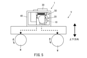
- FIG. 5 is a side view showing a state in which the engine-driven DC supply unit according to Embodiment 1 is mounted on a vehicle.
- 6 is a side view showing a state in which the engine-driven DC supply unit according to Embodiment 1 is placed on the ground or the like.
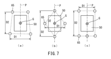
- FIG. FIG. 7 is a plan view schematically showing an arrangement example of elastic bodies that support main components of the engine-driven DC supply unit.
- FIG. 8 is a side view of the engine-driven direct current supply unit according to Embodiment 3 when viewed from a direction perpendicular to the axial direction.
- 9 is an enlarged view of a connecting portion between an elastic body, a base member, and a pair of mount members in an engine-driven DC supply unit according to Embodiment 4.
- FIG. 10 is a side view of the engine-driven direct-current supply unit according to Embodiment 5 when the engine-driven direct-current supply unit is viewed in the axial direction.
- FIG. 11 is a side view of the engine-driven direct current supply unit according to Embodiment 5 when viewed from a direction perpendicular to the axial direction.
- the vertical direction of the engine-driven DC supply unit 1 means the vertical direction when the mount members 61 and 62 support the main component 50 from below.
- the arrangement of the engine-driven direct current supply unit 1 may be an arrangement other than that described above. That is, the vertical direction of the engine-driven DC supply unit 1 is not limited to the above-described direction.
- the axial direction means the direction in which the crankshaft of the engine body 11 and the rotation axis of the generator 21 extend.
- the radial direction means the radial direction of the generator 21 .
- the circumferential direction means the direction of rotation of the generator 21 .
- FIG. 1 is a side view showing a schematic configuration of an engine-driven DC supply unit 1.
- FIG. 1 is a side view showing a schematic configuration of an engine-driven DC supply unit 1.
- the engine-driven DC supply unit 1 supplies electric power to the external load device 2 .
- the engine driven direct current supply unit 1 does not provide mechanical power to the external load device 2 .
- the external load device 2 includes, for example, a power storage or an electrical load.
- the external load device 2 is, for example, a device including a power storage or an electric load, and may be a mobile object or a fixed device that does not move.
- the power storage may be a battery, capacitor, or the like.
- the electrical loads are motors, lighting devices, electrical equipment, and the like.
- the engine drive DC supply unit 1 supplies DC power to the power storage or the electrical load included in the external load device 2 .
- the engine-driven DC supply unit 1 comprises a base member 40 and main components 50 .
- the main component 50 is elastically supported with respect to the base member 40 .
- FIG. 2A is a side view of the engine-driven direct current supply unit 1 when the engine-driven direct current supply unit 1 is viewed in the axial direction.
- FIG. 2B is a bottom view showing a schematic configuration of the engine-driven DC supply unit 1.
- FIG. FIG. 3 is a side view of the engine-driven direct current supply unit 1 viewed from a direction orthogonal to the axial direction.
- the base member 40 is a rectangular parallelepiped frame made up of a plurality of beam members. Also, the main components 50 can be arranged compactly within the base member 40 .
- the base member may be a frame having another shape.
- the base member may be a structure composed of surfaces, such as a box-like shape, instead of a frame.
- the base member may be configured by a plate member or the like.
- the main components 50 include an engine unit 10, a generator unit 20, and a control device 30.
- the engine-driven DC supply unit 1 includes an engine unit 10 , a generator unit 20 , a control device 30 and a base member 40 .
- the engine-driven direct-current supply unit 1 converts electric power generated by the generator unit 20 driven by the engine unit 10 into direct-current power by the control device 30 and outputs the direct-current power.
- the main components 50 are the main components of the engine-driven DC supply unit 1, including the engine unit 10, the generator unit 20, and the control device 30 that controls the engine unit 10 and the generator unit 20. means component.
- a major component 50 is supported by the base member 40 .
- the main component 50 may include components other than the engine unit 10 , the generator unit 20 and the controller 30 .
- the engine unit 10 has an engine body 11 that rotates a crankshaft (not shown).
- the engine unit 10 may include, in addition to the engine body 11, an intake pipe, an air cleaner 12, an exhaust pipe, an exhaust gas processing device 13, and the like.
- Engine unit 10 does not include a fuel tank.
- the crankshaft rotates about an axis P. As shown in FIG. Although not shown, the crankshaft is connected to a rotating shaft that rotates the rotor of the generator 21, which will be described later.
- the generator unit 20 has a generator 21 .
- the generator unit 20 may include, in addition to the generator 21, a fan, terminals, a cover, and the like.
- the generator 21 has a stator and a rotor.
- the rotor is fixed to a rotary shaft connected to the crankshaft of the engine body 11 . Therefore, the rotor rotates integrally with the crankshaft and rotary shaft of the engine body 11 .
- the generator 21 is positioned in the axial direction of the crankshaft with respect to the engine body 11 .
- a generator 21 outputs electric power generated by the rotation of the rotor as described above. A detailed description of the configuration of the generator 21 is omitted.
- the control device 30 controls the engine unit 10 and the generator unit 20, and converts the power generated by the generator 21 driven by the engine body 11 into DC power. That is, the control device 30 has functions as an engine control device, a generator control device, and a power conversion device.
- the control device 30 is housed in a housing.
- control device 30 may have only part of the functions of the engine control device, the generator control device, and the power conversion device. Some of the functions of the engine control device, the generator control device, and the power conversion device may be realized by other devices in the engine-driven DC supply unit 1, or by devices outside the engine-driven DC supply unit 1. may be Moreover, the control device 30 may be configured by a plurality of control devices, or may be configured by a single control device.
- the main component 50 is supported by the base member 40 via a pair of mounting members 61 and 62 and an elastic body 65.
- Each of the pair of mount members 61 and 62 is composed of a plate-like member bent into a U-shape.
- the pair of mount members 61 and 62 are arranged in parallel along the long sides of the rectangular parallelepiped base member 40 .
- the mount member 61 has a bottom portion 61a and a pair of connection portions 61b.
- the bottom portion 61a extends parallel to the axis P of the crankshaft below the main component 50 .
- the pair of connecting portions 61b extends upward from each axial end of the bottom portion 61a.
- the bottom portion 61a and the pair of connection portions 61b are integrally formed.
- the bottom portion 61a and the pair of connection portions 61b may be configured separately and connected to each other.
- the mount member 62 has a bottom portion 62a and a pair of connection portions 62b. Since the configuration of the mount member 62 is the same as that of the mount member 61, detailed description thereof will be omitted.
- the dimension of the mount member 62 in the direction orthogonal to the axis P (hereinafter referred to as the width dimension) is larger than the width dimension of the mount member 61 .
- the width dimension of the mount members 61 and 62 may be the same, or the width dimension of the mount member 62 may be smaller than the width dimension of the mount member 61 .
- connection portions 61b and 62b of the pair of mount members 61 and 62 are connected to the support portion 41 fixed to the base member 40 via the elastic body 65.
- the elastic body 65 is preferably, for example, a metal spring that can expand and contract in one direction.
- the elastic body 65 When the elastic body 65 is easily deformed and the stroke during deformation is large, it is difficult to transmit the vibration generated in the main component 50 to the base member 40 .
- the plurality of elastic bodies 65 are springs as in the configuration described above, the plurality of elastic bodies 65 are easily deformed, and the stroke generated when the elastic bodies 65 are deformed can be increased.
- the plurality of elastic bodies 65 are metal springs, it is possible to increase the stroke generated when the elastic bodies 65 deform while supporting a heavy object such as the main component 50 .
- the engine-driven direct current supply unit 1 is realized that can further improve the vibration transmission suppressing function that suppresses the transmission of the vibration generated in the engine-driven direct current supply unit to the outside while suppressing the change in the posture of the engine-driven direct current supply unit 1. can do.
- vibrations generated in the main component 50 and having a predetermined frequency or higher are not transmitted to the base member 40 via the elastic body 65.
- Vibration of the main component 50 that can be absorbed by the elastic body 65 may be vibration caused by rotational motion or vibration caused by translational motion.
- the elastic body 65 is preferably a tension spring. If the elastic body 65 is, for example, a compression spring, buckling may occur due to the force input from the pair of mount members 61 and 62 to the base member 40 . In contrast, since the elastic body 65 is a tension spring as in the present embodiment, the elastic body 65 is easily deformed in the expansion/contraction direction by the force input from the pair of mount members 61 and 62 to the base member 40 . . Therefore, it is possible to effectively suppress transmission of vibration of the main component 50 from the pair of mount members 61 and 62 to the base member 40 . Moreover, since the elastic body 65 is a tension spring, it is not necessary to provide the engine-driven DC supply unit 1 with a member for preventing buckling, unlike the compression spring. Therefore, the engine-driven DC supply unit 1 can be realized at low cost and lightened.
- the elastic body may be a compression spring or rubber other than a tension spring as long as it is elastically deformable so as to suppress the transmission of vibration from the pair of mount members 61 and 62 to the base member 40 .
- the elastic body may be made of other material such as resin.
- One end (lower end) of the elastic body 65 is connected to the ends of the connection portions 61b and 62b of the pair of mount members 61 and 62.
- the other end (upper end) of the elastic body 65 is connected to the support portion 41 fixed to the base member 40 .
- each of the pair of mount members 61 and 62 is elastically supported at two locations with respect to the base member 40 via the elastic bodies 65 . Therefore, the main component 50 supported by the pair of mount members 61 and 62 is elastically supported at four points with respect to the base member 40 by the pair of mount members 61 and 62 and the elastic body 65 .
- the elastic body 65 is provided between the base member 40 and the pair of mount members 61 and 62 so that the direction of expansion and contraction is the vertical direction.
- FIG. 4 is a plan view showing a schematic configuration of the engine-driven DC supply unit 1.
- FIG. 4 the four elastic bodies 65 are arranged to surround the center of gravity G of the main component 50 in plan view.
- the pair of mounting members 61 and 62 are configured such that the elastic bodies 65 are positioned at four points surrounding the center of gravity G of the main component 50 in plan view.
- the main component 50 is elastically supported by the base member 40 via the elastic bodies 65 at four points surrounding the center of gravity G of the main component 50 in a plan view of the engine-driven direct current supply unit 1 .
- the distance between the two points located in the axial direction extending along the axis P of the crankshaft of the engine body 11 in plan view is It is larger than the distance between the two located points.
- the fact that the elastic bodies 65 are positioned at four points surrounding the center of gravity G of the main component 50 in plan view means that when the engine-driven DC supply unit 1 is viewed in plan, , means that the center of gravity G of the main component 50 is located.
- the center of gravity G of the main component 50 is located within a quadrangular (for example, rectangular) area in which the four elastic bodies 65 are located at the vertices.
- the four elastic bodies 65 may be positioned in a parallelogram shape, a trapezoidal shape, or the like, for example, in a plan view of the engine-driven direct current supply unit 1, or may be positioned in another rectangular shape.
- the properties (e.g., elastic modulus) of the four elastic bodies 65 may be changed according to the arrangement of the four elastic bodies 65 so that transmission of vibration of the main component 50 can be suppressed.
- the positions of the four points are, for example, one position in the axial direction from the center of gravity G of the main component 50 and the other position in the axial direction from the center of gravity G of the main component 50 when the engine-driven direct current supply unit 1 is viewed in plan. , one position in the direction perpendicular to the axial direction relative to the center of gravity G, and the other position in the direction perpendicular to the axial direction relative to the center of gravity G.
- the main component 50 can be more reliably supported on the base member 40 at four points. That is, the engine body 11 and the generator 21 are arranged at four points surrounding the center of gravity G of the main component 50 in plan view in an axial direction extending along the axis P of the crankshaft of the engine body 11 and a direction orthogonal to the axial direction. It is supported by a pair of mount members 61 and 62 via a plurality of elastic bodies 65 arranged respectively in a state in which the posture change is further suppressed. Therefore, it is possible to suppress transmission of vibration from the engine-driven DC supply unit 1 to the outside. Therefore, when the engine-driven direct-current supply unit 1 is placed on a table, it is not necessary to increase the rigidity of the table so as to withstand large vibrations.
- the plurality of elastic bodies 65 are arranged in an axial direction extending along the axis P of the crankshaft of the engine body 11 and in a direction perpendicular to the axial direction (the same as the axial direction in this embodiment). I'm in. That is, the pair of mount members 61 and 62 mount the engine body 11 and the generator 21 to the base member 40 in the axial direction extending along the axis P of the crankshaft of the engine body 11 and in the direction perpendicular to the axial direction. Support is provided via a plurality of elastic bodies 65 arranged side by side.
- the pair of mount members 61 and 62 are arranged at a plurality of positions in at least one of one or the other of the axial directions relative to the center of gravity of the main component 50 via elastic bodies 65 in plan view, for example. , the engine body 11 and the generator 21 may be supported. Thereby, the engine main body 11 and the generator 21 can be supported more reliably.
- the pair of mount members 61 and 62 are mounted at one point in at least one of the axial directions relative to the center of gravity of the main component 50 in a plan view, and the elastic body 65 intervenes between the engine body 11 and the power generator. machine 21 may be supported.
- the plurality of elastic bodies 65 are arranged such that the distance D2 between the two points positioned in the axial direction is the distance between the two points positioned in the direction perpendicular to the axial direction. They are arranged so as to be larger than the interval D1.
- the axial interval D2 of the plurality of elastic bodies 65 means the smallest interval among the intervals between the centers of the elastic bodies 65 arranged in the axial direction.
- the interval D1 in the direction orthogonal to the axial direction means the smallest interval among the intervals between the centers of the elastic bodies 65 arranged in the direction orthogonal to the axial direction.
- the support stiffness of the plurality of elastic bodies 65 in the direction orthogonal to the axial direction is smaller than the support stiffness in the axial direction. Therefore, the plurality of elastic bodies 65 are likely to deform around the axis P of the crankshaft. Therefore, the plurality of elastic bodies 65 can easily absorb the displacement occurring in the direction around the axis P of the crankshaft. Therefore, it is possible to effectively suppress transmission of the vibration of the main component 50 generated in the direction around the axis P of the crankshaft to the base member 40 .
- the engine-driven direct current supply unit 1 is realized that can further improve the vibration transmission suppressing function that suppresses the transmission of the vibration generated in the engine-driven direct current supply unit to the outside while suppressing the change in the posture of the engine-driven direct current supply unit 1. can do.
- the pair of mount members 61 and 62 may be positioned outside the main component 50 in plan view and bottom view.
- the main component 50 may be supported by a pair of mounting members 61 and 62 at the ends of the main component 50 in the longitudinal direction of the rectangular parallelepiped base member 40 .
- the pair of mount members 61 and 62 may be configured such that the elastic body 65 is positioned between the upper end and the lower end of the main component 50 in the vertical direction.
- the main component 50 is supported by a plurality of elastic bodies 65 on its sides and between its upper and lower ends.
- the plurality of elastic bodies 65 can be arranged at positions close to the center of gravity G of the main component 50 in the vertical direction, so that the stroke generated when the elastic bodies 65 are deformed can be reduced. Therefore, it is possible to configure the plurality of elastic bodies 65 to be easily elastically deformed. Therefore, it is possible to more reliably suppress transmission of vibrations generated in the main component 50 to the base member 40 via the plurality of elastic bodies 65 .
- the main component 50 is laterally supported by a pair of mounting members 61 and 62 . Therefore, the degree of freedom in layout of the components of the main component 50 can be improved, and the degree of freedom in designing the shape of the base member 40 that supports the main component 50 can be improved. Therefore, the main components 50 can be collectively arranged to achieve compactness.
- the pair of mount members 61 and 62 suppresses the transmission of vibrations generated in the engine-driven direct current supply unit 1 to the outside, while maintaining the degree of freedom in the layout of the components in the engine-driven direct current supply unit 1 and the shape of the base member 40. can improve the degree of design freedom. Therefore, the versatility of the engine-driven DC supply unit 1 can be enhanced.
- the engine body 11 and the generator 21 are supported by a plurality of vertical support portions 63 arranged on the bottom portions 61a and 62a of the pair of mount members 61 and 62. Thereby, the vertical positions of the engine body 11 and the generator 21 can be adjusted.
- FIG. 5 is a side view schematically showing a case where the engine-driven direct current supply unit 1 is mounted on a moving body (vehicle V), which is an example of an external load device.
- FIG. 6 is a side view schematically showing how power is supplied to an external load device 2 (for example, a battery) with the engine-driven DC supply unit 1 placed on the ground M.
- the engine-driven DC supply unit 1 may be mounted on a moving body (vehicle V) or may be placed on the ground M.
- the engine-driven DC supply unit 1 may be attached to a mobile object or a fixed device as long as it can supply DC power to the external load device 2, or it may be mounted on the ground M, It may be placed on a table, other device, or the like.
- the engine-driven DC supply unit 1 may, for example, charge a battery of a mobile object.
- the battery of the mobile body may be detachable from the mobile body, or may be fixed to the mobile body.
- the engine-driven DC supply unit 1 may, for example, charge a battery of an electric power tool or an electric working machine.
- the engine-driven DC supply unit 1 may supply electric power to, for example, a lighting device.
- the engine-driven direct-current supply unit 1 may supply electric power to a drive source such as a pump motor, a compressor motor, or the like.
- the mobile body means an object that can be moved by power, such as a vehicle, an aircraft, and a ship.
- the moving object also includes a vehicle.
- the moving body is equipped with a power unit (such as a motor) that generates power from energy supplied from an energy source.
- the energy source is, for example, the engine-driven DC supply unit 1 of this embodiment, a battery, or the like.
- the engine-driven DC supply unit 1 does not provide mechanical power to the moving body.
- the engine unit 10 and the generator unit 20 which will be described later, provide mechanical running power to the moving body. It does not receive drive reaction force like the parallel hybrid engine unit provided. Therefore, the supporting rigidity of the engine unit 10 and the generator unit 20 can be made smaller than the supporting rigidity of the engine in the parallel hybrid engine unit.
- the moving object is a vehicle V.
- DC power output from the engine drive DC supply unit 1 is supplied to a motor (not shown) that drives the wheels W of the vehicle V as indicated by the dashed arrow.
- the direct current power output from the engine driving direct current supply unit 1 is used to drive the front and rear wheels of the vehicle V by the motor. good too.
- the vehicle V is equipped with a battery (not shown), and the DC power output from the engine driving DC supply unit 1 is charged in the battery, and the power of the battery is used to drive the wheels W by the motor. good.
- the configuration of the engine-driven direct-current supply unit 1 that can be attached to or detached from a moving body (vehicle V), which is an example of the external load device 2, will be described below.
- the base member 40 is fixed to the vehicle V.
- the method of fixing the base member 40 to the vehicle V may be any method such as fastening using bolts, fitting, adhesion, welding, or the like.
- the base member 40 is a rectangular parallelepiped frame made up of a plurality of beam members. As a result, a space for arranging the base member 40 on the moving body can be easily secured, and the base member 40 can be more securely fixed to the moving body.
- the structure of the unit is configured such that the elastic body easily deforms around the axis of the crankshaft as in the present embodiment, the position of the engine will change greatly due to the drive reaction force, and the desired function of the unit will not be achieved. may not be obtained. That is, the configuration of the present embodiment exerts an effect only on the engine-driven DC supply unit 1 that does not provide mechanical driving power to the moving body, and the unit such as the above-mentioned parallel hybrid engine. cannot be applied to
- FIG. 7 is a plan view schematically showing an arrangement example of the elastic bodies 65 that support the main components 50 of the engine-driven DC supply unit 1 according to the first embodiment.
- illustration of the configuration other than the main component 50 in the engine-driven DC supply unit 1 is omitted for explanation.
- the main component 50 is attached to a base member (not shown) via elastic bodies 65 at four points surrounding the center of gravity G of the main component 50 in a plan view of the engine-driven direct current supply unit 1. elastically supported.
- the positions of the four points are, for example, one position in the axial direction from the center of gravity G of the main component 50 and the other position in the axial direction from the center of gravity G in the plan view of the engine-driven direct current supply unit 1,
- One position in the direction perpendicular to the axial direction relative to the center of gravity G and the other position in the direction perpendicular to the axial direction relative to the center of gravity G are included.
- the distance D2 between the elastic bodies 65 located at one position and the other position in the axial direction with respect to the center of gravity G of the main component 50 is is larger than the interval D1 between the elastic bodies 65 located at one position and the other position in the direction orthogonal to the axial direction.
- the distance D1 between the elastic bodies 65 located at one position and the other position in the axial direction with respect to the center of gravity G is It means the maximum distance among the distances in the axial direction.
- the distance D2 between the elastic bodies 65 located at one position and the other position in the direction orthogonal to the axial direction with respect to the center of gravity G is means the maximum interval among the intervals in the direction perpendicular to the axial direction.
- the plurality of elastic bodies 65 that support the main components 50 may be arranged in a trapezoidal shape when the engine-driven direct current supply unit 1 is viewed from above. That is, the distance between the elastic bodies 65 positioned at one position and the other position in the direction perpendicular to the axial direction with respect to the center of gravity G is equal to the distance between the elastic bodies 65 positioned at one position with respect to the center of gravity G in the axial direction.
- the spacing in the body 65 may be different from the spacing in the plurality of elastic bodies 65 located on the other side of the center of gravity G in the axial direction.
- the plurality of elastic bodies 65 that support the main components 50 may be arranged in a rectangular or polygonal shape other than the trapezoidal shape in plan view of the engine-driven direct current supply unit 1 .
- the plurality of elastic bodies 65 that support the main components 50 may be arranged in a rhombic shape when the engine-driven DC supply unit 1 is viewed from above. That is, the main component 50 is supported by elastic bodies 65 at one position and the other position with respect to the center of gravity G in the axial direction. One position and one other position are supported by elastic bodies 65 .
- the plurality of elastic bodies 65 that support the main components 50 are positioned three in one of the axial directions with respect to the center of gravity G in a plan view of the engine-driven DC supply unit 1.
- the plurality of elastic bodies 65 that support the main components 50 may be positioned four or more in one of the axial directions with respect to the center of gravity G in a plan view of the engine-driven direct current supply unit 1 .
- the plurality of elastic bodies 65 that support the main components 50 may be positioned three or more on one side and the other side in the axial direction with respect to the center of gravity G in a plan view of the engine-driven direct current supply unit 1 .
- Three or more of the plurality of elastic bodies 65 that support the main components 50 may be positioned in one of the directions orthogonal to the axial direction with respect to the center of gravity G in a plan view of the engine-driven direct current supply unit 1 .
- the plurality of elastic bodies 65 supporting the main components 50 are positioned three or more in one direction and the other direction perpendicular to the axial direction with respect to the center of gravity G in a plan view of the engine-driven direct current supply unit 1. good too.
- the main component 50 can be more reliably supported at four points on the base member (not shown).
- FIG. 8 is a side view showing a schematic configuration of an engine-driven DC supply unit 200 according to Embodiment 3.
- the elastic bodies 65 are located in three regions S near the center in the vertical direction of regions obtained by vertically dividing the space between the upper end and the lower end of the main component 50 into five equal parts.
- the same reference numerals are given to the same configurations as in the first embodiment, and the description thereof is omitted, and only the portions different from the configuration of the first embodiment will be described.
- 8 shows only the configuration of the mount member 262, the configuration of the mount member 261 is similar to that of the mount member 262.
- reference numeral 262a is the bottom portion and reference numeral 262b is the connecting portion.
- At least one of the pair of mount members 261 and 262 and the support portion 241 is positioned between the upper end and the lower end of the main component 50 when the engine-driven DC supply unit 200 is viewed from the side. are located in three regions S close to the center in the vertical direction of regions obtained by equally dividing the region into five in the vertical direction.
- the elastic body 65 divides the area between the upper end and the lower end of the main component 50 into five in the vertical direction when viewed from the side of the engine-driven direct current supply unit 200, and the three regions S near the center in the vertical direction.
- the pair of mounting members 261 and 262 and the supporting portion 241 may have any configuration as long as they are located inside.
- the elastic body 65 may be positioned within the hatched area in FIG. 8.
- the elastic body 65 can be arranged at a position close to the center of gravity G of the main component 50 in the vertical direction, so that the stroke generated when the elastic body 65 is deformed can be reduced. Therefore, the elastic body 65 can be configured to be easily elastically deformed. Therefore, transmission of vibration generated in the main component 50 to the base member 40 via the elastic body 65 can be suppressed more reliably. Moreover, by arranging the elastic bodies 65 as described above, the degree of freedom in layout of the constituent parts of the main component 50 can be improved.
- the elastic body 65 is positioned in the central area in the vertical direction of the area obtained by vertically dividing the space between the upper end and the lower end of the main component 50 into five equal parts. As a result, since the elastic body 65 can be arranged closer to the center of gravity G of the main component 50 in the vertical direction, transmission of vibration from the main component 50 to the base member 40 can be effectively suppressed.
- FIG. 9 is an enlarged view of a connecting portion between the elastic body 65 and the base member 40 and the pair of mount members 361 and 362 in the engine-driven DC supply unit 300 according to the fourth embodiment.
- the elastic body 365 is rotatably connected to the base member 40 and the pair of mount members 361 and 362, which is different from the configurations of the first and third embodiments.
- the same reference numerals are given to the same configurations as in the first embodiment, and the description thereof is omitted, and only the portions different from the configuration of the first embodiment will be described.
- the elastic body 365 has C-shaped hook portions 365a and 365b at both ends.
- the hook portions 365a and 365b of the elastic body 365 have openings that open sideways.
- the opening direction of the opening of the hook portion 365 a provided at one end (lower end) of the elastic body 365 is the other end of the elastic body 365 . It is the opposite direction to the opening direction of the opening of the hook portion 365b provided at the end (upper end).
- the hook portion 365a of the elastic body 365 is inserted through the hole of the ring portion 361c provided on the connection portion 361b of the mount member 361 or the hole of the ring portion 362c provided on the connection portion 362b of the mount member 362.
- a hook portion 365a of the elastic body 365 corresponds to the second end portion.
- the hook portion 365 b of the elastic body 365 is inserted through the hole of the ring portion 341 a provided in the support portion 341 .
- a hook portion 365b of the elastic body 365 corresponds to the first end portion.
- the hook portions 365a and 365b of the elastic body 365 are C-shaped as described above, they are rotatably connected to the ring portions 361c, 362c and 341a. Therefore, the elastic body 365 is rotatable with respect to the mount members 361 and 362 or the support portion 341 .
- the elastic body 365 is arranged to allow the pair of mount members 361 and 361 to move in such a way that the force input direction coincides with the expansion and contraction direction. , 362 or relative to the base member 40 . Accordingly, even when the pair of mount members 361 and 362 are displaced in a direction other than the vertical direction with respect to the base member 40, the deformation of the elastic body 365 transmits vibration from the pair of mount members 361 and 362 to the base member 40. can be suppressed.
- the hook portion 365b connected to the base member 40 in the elastic body 365 is rotatably connected to the base member 40.
- a hook portion 365a connected to the mount members 361 and 362 in the elastic body 365 is rotatably connected to the mount members 361 and 362 .
- the rotation of at least one of the hook portions 365a and 365b of the elastic body 365 causes the displacement.
- the elastic body 365 is easily deformed in the expansion/contraction direction. Therefore, the elastic body 365 can more effectively suppress transmission of the vibration of the main component 50 to the base member 40 via the pair of mount members 361 and 362 .
- FIG. 10 is a side view of the engine-driven direct-current supply unit 400 according to the fifth embodiment when the engine-driven direct-current supply unit 400 is viewed in the axial direction.
- FIG. 11 is a side view of the engine-driven direct current supply unit 400 viewed from a direction perpendicular to the axial direction.
- the engine drive direct current supply unit 400 has a regulating portion (first regulating portion 401, second regulating portion 402, third regulating portion 403) that regulates relative movement of the pair of mount members 61 and 62 with respect to the base member 40 within a predetermined range. (stopper portion).
- first regulating portion 401, second regulating portion 402, third regulating portion 403 that regulates relative movement of the pair of mount members 61 and 62 with respect to the base member 40 within a predetermined range. (stopper portion).
- the base member 40 has a plurality of first restricting portions 401 that restrict the movement range of the pair of mount members 61 and 62 within a first predetermined range in the direction orthogonal to the axial direction. is provided.
- the plurality of first restricting portions 401 are arranged such that the pair of mount members 61 and 62 are positioned between the plurality of first restricting portions 401 when the engine drive direct current supply unit 400 is viewed in the axial direction.
- the first predetermined range is a range in which the pair of mount members 61 and 62 do not come into contact with other components of the engine-driven DC supply unit 400 when the pair of mount members 61 and 62 are displaced with respect to the base member 40.
- the number of the first restricting portions 401 provided on the base member 40 may be one.
- a plurality of second restricting portions 402 are provided on the lower surfaces of the bottom portions 61a and 62a of the pair of mount members 61 and 62, respectively, to restrict the movement range of the pair of mount members 61 and 62 within a second predetermined range in the vertical direction. It is The plurality of second restricting portions 402 are arranged on the connecting portions 61b and 62b sides of the bottom portions 61a and 62a when the engine-driven DC supply unit 400 is viewed in a direction orthogonal to the axial direction.
- the second predetermined range is a range in which the pair of mount members 61 and 62 do not contact the bottom surface of the base member 40 when the pair of mount members 61 and 62 are displaced with respect to the base member 40 . It should be noted that the pair of mount members 61 and 62 may each have one second restricting portion 402 provided thereon.
- a plurality of third actuators for restricting the movement range of the pair of mount members 61 and 62 within a third predetermined range in the axial direction.
- a regulation unit 403 is provided.
- the plurality of third restricting portions 403 are provided in the pair of mount members 61 and 62 so as to protrude in the axial direction from the connecting portions 61b and 62b located at both ends of the bottom portions 61a and 62a in the axial direction.
- the plurality of third restricting portions 403 also protrude downward from the connecting portions 61b and 62b.
- the third predetermined range is a range in which the pair of mount members 61 and 62 do not contact the base member 40 in the axial direction when the pair of mount members 61 and 62 are displaced with respect to the base member 40 .
- the main component 50 supported by the pair of mount members 61 and 62 is largely displaced with respect to the base member 40 due to the deformation of the elastic body 65 caused by the vibration generated in the main component 50. can be suppressed. Therefore, it is possible to prevent the main component 50 from contacting the base member 40 or being displaced out of the base member 40 .
- the restricting portion may be provided on the base member 40 so as to restrict the main component 50 in the X direction and the Y direction. Alternatively, it may be provided to restrict the main component 50 in the Y and Z directions, or may be provided to restrict the main component 50 in the Z and X directions. Furthermore, the restricting portion may be provided on the base member 40 so as to restrict the main component 50 in the X, Y and Z directions.
- the engine-driven DC supply units 1, 200, 300, 400 have a pair of mounting members 61, 62, 261, 262, 361, 362.
- the engine driven direct current supply unit may have only one mounting member, or may have three or more mounting members.
- the engine-driven DC supply units 1, 200, 300, 400 have four elastic bodies 65, 365.
- the engine driven direct current supply unit may have more than five elastic bodies.
- four elastic bodies out of the plurality of elastic bodies are arranged in the axial direction and in a direction orthogonal to the axial direction, and are spaced apart in the front axial direction in the direction orthogonal to the axial direction in plan view. It is sufficient if they are arranged so as to be larger than the interval.
- the plurality of elastic bodies 65, 365 are provided between the base member 40 and the pair of mount members 61, 62 such that the direction of expansion and contraction is the vertical direction.
- the plurality of elastic bodies may be provided between the base member and the pair of mount members so that the directions of expansion and contraction are in directions other than the vertical direction.
- the mount members 61, 62, 261, 262, 361, and 362 are at least partially positioned outside the main component 50 in plan view and bottom view, and have a plurality of elastic bodies 65 in the vertical direction. , 365 are positioned between the top and bottom ends of the main component 50 .
- the mounting member may be located inwardly of the main component in plan view and bottom view.
- the plurality of elastic bodies may be positioned above the upper end of the main component or may be positioned below the lower end of the main component.
- the main component is supported by a plurality of elastic bodies, but the number of elastic bodies that support the main component may be one.
- the elastic bodies 65 are located in the three areas S near the center in the vertical direction among the areas obtained by vertically dividing the space between the upper end and the lower end of the main component 50 into five equal parts.
- the elastic body may be positioned in a region other than the three regions S near the center in the vertical direction of the five equally divided regions.
- the elastic body 365 is rotatably connected to the base member 40 and the pair of mount members 361 and 362 .
- the elastic body may be fixed to at least one of the base member and the pair of mount members.
- the elastic body 365 has C-shaped hook portions 365a and 365b, and the support portion 341 and the pair of mount members 361 and 362 have ring portions 341a, 361c and 362c.
- the elastic body may be connected to the base member and the pair of mount members in any way as long as it can rotate with respect to the base member and the pair of mount members.
- the elastic body may be rotatably connected to only one of the base member or the pair of mount members. Further, the elastic body may be connected to at least one of the base member and the pair of mount members so as to be rotatable about the axis of the elastic body.
- the base member 40 is provided with the first restricting portion 401 that restricts the movement range of the pair of mount members 61 and 62 within the first predetermined range in the direction perpendicular to the axial direction.
- the first restricting portion may be provided on the pair of mount members.
- the first restricting portion may be provided on a supporting portion fixed to the base member.
- the engine-driven DC supply unit may not have the first restrictor.
- the second restricting portion 402 is provided on the lower surfaces of the bottom portions 61a and 62a of the pair of mount members 61 and 62.
- the second restricting portion may be provided at a portion of the bottom surface of the base member located below the pair of mount members.
- the engine-driven DC supply unit may not have the second restrictor.
- the connecting portions 61b and 62b of the pair of mount members 61 and 62 are provided with the third restricting portions 403.
- the third restricting portion may be provided at a portion of the base member that is axially positioned with respect to the connecting portion of the pair of mount members.
- the engine-driven DC supply unit may not have the third restrictor.
Landscapes
- Engineering & Computer Science (AREA)
- Chemical & Material Sciences (AREA)
- Combustion & Propulsion (AREA)
- Transportation (AREA)
- Mechanical Engineering (AREA)
- Automation & Control Theory (AREA)
- Power Engineering (AREA)
- Vibration Prevention Devices (AREA)
- Arrangement Or Mounting Of Propulsion Units For Vehicles (AREA)
Priority Applications (3)
| Application Number | Priority Date | Filing Date | Title |
|---|---|---|---|
| JP2024500848A JPWO2023157221A1 (https=) | 2022-02-18 | 2022-02-18 | |
| PCT/JP2022/006595 WO2023157221A1 (ja) | 2022-02-18 | 2022-02-18 | エンジン駆動直流供給ユニット |
| US18/807,635 US20240399846A1 (en) | 2022-02-18 | 2024-08-16 | Engine-driven-dc-supply unit |
Applications Claiming Priority (1)
| Application Number | Priority Date | Filing Date | Title |
|---|---|---|---|
| PCT/JP2022/006595 WO2023157221A1 (ja) | 2022-02-18 | 2022-02-18 | エンジン駆動直流供給ユニット |
Related Child Applications (1)
| Application Number | Title | Priority Date | Filing Date |
|---|---|---|---|
| US18/807,635 Continuation-In-Part US20240399846A1 (en) | 2022-02-18 | 2024-08-16 | Engine-driven-dc-supply unit |
Publications (1)
| Publication Number | Publication Date |
|---|---|
| WO2023157221A1 true WO2023157221A1 (ja) | 2023-08-24 |
Family
ID=87577983
Family Applications (1)
| Application Number | Title | Priority Date | Filing Date |
|---|---|---|---|
| PCT/JP2022/006595 Ceased WO2023157221A1 (ja) | 2022-02-18 | 2022-02-18 | エンジン駆動直流供給ユニット |
Country Status (3)
| Country | Link |
|---|---|
| US (1) | US20240399846A1 (https=) |
| JP (1) | JPWO2023157221A1 (https=) |
| WO (1) | WO2023157221A1 (https=) |
Citations (4)
| Publication number | Priority date | Publication date | Assignee | Title |
|---|---|---|---|---|
| JPH10299533A (ja) * | 1997-02-20 | 1998-11-10 | Honda Motor Co Ltd | 内燃機関用の発電電動装置 |
| JPH11103506A (ja) * | 1997-09-29 | 1999-04-13 | Nissan Diesel Motor Co Ltd | ハイブリッド電気自動車のインバータ取付構造 |
| JP2010083261A (ja) * | 2008-09-30 | 2010-04-15 | Mazda Motor Corp | 車体前部構造 |
| JP2011073582A (ja) * | 2009-09-30 | 2011-04-14 | Mazda Motor Corp | エンジン搭載の電気自動車の前部構造 |
-
2022
- 2022-02-18 WO PCT/JP2022/006595 patent/WO2023157221A1/ja not_active Ceased
- 2022-02-18 JP JP2024500848A patent/JPWO2023157221A1/ja active Pending
-
2024
- 2024-08-16 US US18/807,635 patent/US20240399846A1/en active Pending
Patent Citations (4)
| Publication number | Priority date | Publication date | Assignee | Title |
|---|---|---|---|---|
| JPH10299533A (ja) * | 1997-02-20 | 1998-11-10 | Honda Motor Co Ltd | 内燃機関用の発電電動装置 |
| JPH11103506A (ja) * | 1997-09-29 | 1999-04-13 | Nissan Diesel Motor Co Ltd | ハイブリッド電気自動車のインバータ取付構造 |
| JP2010083261A (ja) * | 2008-09-30 | 2010-04-15 | Mazda Motor Corp | 車体前部構造 |
| JP2011073582A (ja) * | 2009-09-30 | 2011-04-14 | Mazda Motor Corp | エンジン搭載の電気自動車の前部構造 |
Also Published As
| Publication number | Publication date |
|---|---|
| JPWO2023157221A1 (https=) | 2023-08-24 |
| US20240399846A1 (en) | 2024-12-05 |
Similar Documents
| Publication | Publication Date | Title |
|---|---|---|
| CN111497595B (zh) | 串联混合动力车辆中的驱动装置的搭载结构 | |
| JPH034756Y2 (https=) | ||
| CN105987136B (zh) | 用于发动机的自动传动带张紧器 | |
| JP2012101569A (ja) | 車両の駆動装置 | |
| US8362660B2 (en) | Electric generator | |
| KR20120086721A (ko) | 전기 모터 | |
| US20200086731A1 (en) | Powertrain | |
| CN112477599B (zh) | 电气设备的车载构造 | |
| JP7566909B2 (ja) | ベアリングを受容するためのベアリングホルダ | |
| WO2023157221A1 (ja) | エンジン駆動直流供給ユニット | |
| KR102017593B1 (ko) | 전기자동차의 배터리용 트레이와 크래들의 마운팅 구조 | |
| AU2019470673B2 (en) | Engine-generator set | |
| JPH1199834A (ja) | ハイブリッド車の動力装置搭載構造 | |
| CN222346679U (zh) | 作动器、主动悬架以及车辆 | |
| JP2022168575A (ja) | 駆動モータモジュール | |
| JP7461922B2 (ja) | シリーズハイブリッド化エンジン駆動電力供給ユニット及び電動移動体 | |
| US20240399894A1 (en) | Engine-driven dc supply unit | |
| JP7740524B2 (ja) | 電動車両の駆動ユニット | |
| US20250214408A1 (en) | Mounting structure for electrical device | |
| CN115335617A (zh) | 用于降低车辆噪声和振动的系统 | |
| US11255405B2 (en) | Vibration prevention in a linear actuator | |
| US12529331B2 (en) | Motor-generator, power generation apparatus, and mobility device | |
| JP2021046003A (ja) | ハイブリッド駆動装置 | |
| CN223754551U (zh) | 一种模块化减振器 | |
| CN222339111U (zh) | 一种发动机前端单发电机支架 |
Legal Events
| Date | Code | Title | Description |
|---|---|---|---|
| 121 | Ep: the epo has been informed by wipo that ep was designated in this application |
Ref document number: 22927123 Country of ref document: EP Kind code of ref document: A1 |
|
| ENP | Entry into the national phase |
Ref document number: 2024500848 Country of ref document: JP Kind code of ref document: A |
|
| NENP | Non-entry into the national phase |
Ref country code: DE |
|
| 122 | Ep: pct application non-entry in european phase |
Ref document number: 22927123 Country of ref document: EP Kind code of ref document: A1 |