WO2023153261A1 - 放電装置 - Google Patents
放電装置 Download PDFInfo
- Publication number
- WO2023153261A1 WO2023153261A1 PCT/JP2023/002919 JP2023002919W WO2023153261A1 WO 2023153261 A1 WO2023153261 A1 WO 2023153261A1 JP 2023002919 W JP2023002919 W JP 2023002919W WO 2023153261 A1 WO2023153261 A1 WO 2023153261A1
- Authority
- WO
- WIPO (PCT)
- Prior art keywords
- electrode
- discharge
- dielectric
- case
- discharge device
- Prior art date
- Legal status (The legal status is an assumption and is not a legal conclusion. Google has not performed a legal analysis and makes no representation as to the accuracy of the status listed.)
- Ceased
Links
Images













Classifications
-
- B—PERFORMING OPERATIONS; TRANSPORTING
- B03—SEPARATION OF SOLID MATERIALS USING LIQUIDS OR USING PNEUMATIC TABLES OR JIGS; MAGNETIC OR ELECTROSTATIC SEPARATION OF SOLID MATERIALS FROM SOLID MATERIALS OR FLUIDS; SEPARATION BY HIGH-VOLTAGE ELECTRIC FIELDS
- B03C—MAGNETIC OR ELECTROSTATIC SEPARATION OF SOLID MATERIALS FROM SOLID MATERIALS OR FLUIDS; SEPARATION BY HIGH-VOLTAGE ELECTRIC FIELDS
- B03C3/00—Separating dispersed particles from gases or vapour, e.g. air, by electrostatic effect
- B03C3/34—Constructional details or accessories or operation thereof
- B03C3/40—Electrode constructions
- B03C3/41—Ionising-electrodes
-
- H—ELECTRICITY
- H01—ELECTRIC ELEMENTS
- H01T—SPARK GAPS; OVERVOLTAGE ARRESTERS USING SPARK GAPS; SPARKING PLUGS; CORONA DEVICES; GENERATING IONS TO BE INTRODUCED INTO NON-ENCLOSED GASES
- H01T19/00—Devices providing for corona discharge
-
- H—ELECTRICITY
- H01—ELECTRIC ELEMENTS
- H01T—SPARK GAPS; OVERVOLTAGE ARRESTERS USING SPARK GAPS; SPARKING PLUGS; CORONA DEVICES; GENERATING IONS TO BE INTRODUCED INTO NON-ENCLOSED GASES
- H01T19/00—Devices providing for corona discharge
- H01T19/02—Corona rings
-
- H—ELECTRICITY
- H01—ELECTRIC ELEMENTS
- H01T—SPARK GAPS; OVERVOLTAGE ARRESTERS USING SPARK GAPS; SPARKING PLUGS; CORONA DEVICES; GENERATING IONS TO BE INTRODUCED INTO NON-ENCLOSED GASES
- H01T19/00—Devices providing for corona discharge
- H01T19/04—Devices providing for corona discharge having pointed electrodes
-
- H—ELECTRICITY
- H01—ELECTRIC ELEMENTS
- H01T—SPARK GAPS; OVERVOLTAGE ARRESTERS USING SPARK GAPS; SPARKING PLUGS; CORONA DEVICES; GENERATING IONS TO BE INTRODUCED INTO NON-ENCLOSED GASES
- H01T23/00—Apparatus for generating ions to be introduced into non-enclosed gases, e.g. into the atmosphere
Definitions
- the present invention relates to a discharge device in which at least one of a pair of electrodes is rod-shaped.
- This discharge device can be applied to an ozone generator (ozonizer) that generates ozone by electric discharge in the air, an ion generator (ionizer) that generates various ions (negative ions, hydroxyl radicals, etc.).
- ozone generator ozonizer
- ion generator ionizer
- Patent Document 1 for example, can be cited as a prior art document related to this type of discharge device.
- the corona discharge device of Patent Literature 1 includes a flat plate electrode arranged on a support base, and a linear discharge electrode separated from the surface of the flat plate electrode and arranged in parallel.
- the support table has a pair of supports located on both sides of the flat plate electrode, and the linear discharge electrode is stretched between these supports via a coil spring.
- the coil spring has hooks at both ends. One hook is hooked to a crimping terminal fixed to the end of the linear discharge electrode, and the other hook is hooked to a hook-shaped terminal provided on the support. is hooked.
- a positive high voltage is applied from the power supply to the linear discharge electrode via the hook-shaped terminal, coil spring and crimped terminal.
- a negative high voltage is applied from the power source to the flat plate electrode, thereby generating discharge between the linear discharge electrode and the flat plate electrode.
- one hook portion of the coil spring and the annular caulking terminal are in point contact, and the other hook portion and the hook-shaped terminal of the support are also in point contact.
- each hook portion and each terminal are in point contact, that is, if the contact area is small, the contact pressure increases in inverse proportion to the same area, which raises concerns about the long-term durability of the contact portion. Also, if the contact area between each hook and each terminal is small, poor conduction is likely to occur when these surfaces are oxidized over time, and the voltage applied to the linear discharge electrode may drop.
- the present invention has been made to solve these problems. aim.
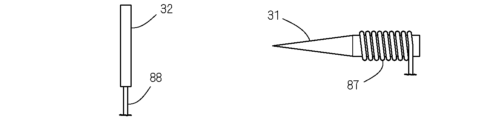
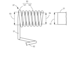
- the discharge device includes a rod-shaped first electrode 31 and a second electrode 32 paired with the first electrode 31 . It has a first conducting body 87 responsible for energizing the first electrode 31, and an electrode connection part 90 is provided at one end of the first conducting body 87 so as to be wound around the first electrode 31 one or more times in the circumferential direction. characterized by
- the second electrode 32 is formed in a bar shape, and has a second current-carrying body 88 that conducts current to the second electrode 32 .
- a form in which an electrode connecting portion 90 to be wound is provided can be adopted.
- a form in which the second electrode 32 is formed in a planar shape can be adopted.
- a configuration can be adopted in which a winding portion 91 that biases the electrode connection portion 90 of the first conductor 87 away from the first electrode 31 is provided.
- a plate-like dielectric 33 is arranged between the first electrode 31 and the second electrode 32 .
- a form in which the biasing force acting on the electrode 31 is received by the dielectric 33 can be adopted.
- a discharge case 34 is provided to accommodate the electrodes 31 and 32 and the dielectric 33.
- the discharge case 34 is provided with a lower receiving portion 72 for receiving the surface of the dielectric 33 on the second electrode 32 side. be able to.
- It has a discharge case 34 that accommodates the two electrodes 31 and 32 and the dielectric 33, and the discharge case 34 is provided with a lower receiving portion 72 that receives the second electrode 32 from the back side of the dielectric 33. can be done.
- a form in which a cushion material 58 is arranged between the lower receiving portion 72 of the discharge case 34 and the dielectric 33 or the second electrode 32 can be adopted.
- the second electrode 32 is formed in a rod shape, and a plate-shaped dielectric 33 is arranged between the first electrode 31 and the second electrode 32 .
- a form in which the biasing force acting on 31 is received by dielectric 33 can be adopted.
- a discharge case 34 is provided to accommodate the electrodes 31 and 32 and the dielectric 33.
- the discharge case 34 is provided with a lower receiving portion 72 for receiving the surface of the dielectric 33 on the second electrode 32 side. be able to.
- It has a discharge case 34 that accommodates the two electrodes 31 and 32 and the dielectric 33, and the discharge case 34 is provided with a lower receiving portion 72 that receives the second electrode 32 from the back side of the dielectric 33. can be done.
- a form in which a cushion material 58 is arranged between the lower receiving portion 72 of the discharge case 34 and the dielectric 33 or the second electrode 32 can be adopted.
- a pair of electrode support structures 64 that support both ends of the first electrode 31 are provided in the discharge case 34 that accommodates the two electrodes 31 and 32 . It is possible to adopt a form composed of an upper support portion 65 and a lower support portion 66 that are sandwiched from above and below.
- a pair of electrode support structures 64 that support both ends of the first electrode 31 are provided in the discharge case 34 that accommodates the two electrodes 31 and 32, and each electrode support structure 64 is laterally opened to open the first electrode. It is possible to take a form constituted by holding grooves 118 that hold the body 31 so as not to move up and down.
- the first electrode 31, the dielectric 33, and the second electrode 32 are arranged vertically to form an electrode unit 71, and the entire electrode unit 71 is sandwiched in the discharge case 34 from above and below. can be done.
- a configuration in which the electrode unit 71 is sandwiched from above and below together with the cushion material 58 within the discharge case 34 can be adopted.
- the first electrode 31 is connected to the first terminal 85 via the first conductor 87 , and the upper discharge section 16 including the first electrode 31 and the first conductor 87 is connected to the lower side including the first terminal 85 . can be detachably attached to the base portion 15 of the .
- a terminal connection portion 92 made of a compression spring that expands and contracts in the vertical direction is provided at the other end of the first conductor 87 .
- a form in which the lower end of 92 is elastically brought into close contact with the first terminal 85 can be adopted.
- a form in which the first conductor 87 integrally includes the electrode connection portion 90 and the terminal connection portion 92 can be adopted.
- a winding portion 91 is provided between the electrode connecting portion 90 and the terminal connecting portion 92 to bias one end of the electrode connecting portion 90 downward. It can be formed in an L-shape having a vertical portion extending downward from the bottom of the vertical portion and a horizontal portion extending laterally from the bottom end of the vertical portion toward the top end of the terminal connection portion 92 .
- the discharge part 16 includes a discharge case 34 that supports the first electrode 31 and the first current-carrying body 87 , and a downward seat that receives the upper end of the terminal connection part 92 and the horizontal part of the winding part 91 on the inner surface of the discharge case 34 .
- a form in which the portion 94 is provided can be adopted.
- An annular or C-shaped first contact 95 is formed at the lower end of the terminal connection portion 92, and a spring receiving portion 96 that fits inside the first contact 95 is protruded from the upper surface of the first terminal 85. can be taken.
- the discharge section 16 includes a discharge case 34 that supports the first electrode 31 and the first conductor 87, and has a storage boss 99 that surrounds the terminal connection section 92 inside the discharge case 34. be able to.
- the discharge case 34 is configured by vertically joining the outer case 37 and the inner case 38, and the storage boss 99 projects downward from the upper wall 61 of the outer case 37 toward the inner case 38.
- a form in which the inner case 38 is provided with a vertical insertion hole 100 for allowing the insertion of the tip of the boss 99 can be adopted.
- the tip of the storage boss 99 may be flush with the lower end of the insertion hole 100 or positioned above the lower end.
- the upper half portion of the terminal connection portion 92 can be accommodated inside the accommodation boss 99 . .
- a discharge opening 35 that exposes the first electrode 31 upward is formed in the upper surface of a discharge case 34 that accommodates both electrodes 31 and 32 , and the discharge opening 35 protrudes above the first electrode 31 around the discharge opening 35 .
- a form in which protective portions 81 and 82 are provided can be adopted.
- the protection part 81 can adopt a form composed of a pair of electrode support structures 64 that support both ends of the first electrode 31 .
- the protection part 82 can adopt a form composed of a pair of ridges 74 extending parallel to the first electrode 31 with the discharge opening 35 therebetween.
- each protection portion 82 formed by the ridges 74 is provided with an inclined guide surface 121 inclined downward toward the first electrode 31 .
- a plate-like dielectric 33 sandwiched between a first electrode 31 and a second electrode 32, and a discharge case 34 that accommodates the electrodes 31 and 32 and the dielectric 33 are provided.
- a discharge opening 35 that exposes the electrode 31 and the dielectric 33 upward, and upward grooves 73 adjacent to both sides of the discharge opening 35 are provided, and the top surface of the dielectric 33 and the bottom surface of the groove 73 are flush with each other. It can take any form.
- a configuration can be adopted in which the adjacent direction of the discharge opening 35 and the groove portion 73 coincides with the extending direction of the first electrode 31 .
- a pair of ridges 74 extending parallel to the first electrode 31 are provided on the upper surface of the discharge case 34 with the discharge opening 35 therebetween. , and end guide surfaces 76 that partition the grooves 73 continuously at both ends of the central guide surface 75 .
- a form in which the central guide surface 75 protrudes toward the first electrode 31 can be adopted.
- the discharge portion 16 includes a discharge case 34 that supports the first electrode 31 and the first conductor 87.
- the discharge portion 16 is separated from the base portion 15 and the terminal connection portion 92 is restored to its natural length, the terminal connection is performed.
- a form in which the lower end of the portion 92 is positioned above the lower end of the discharge case 34 can be adopted.
- an electrode connecting portion 90 that is wound around the first electrode 31 in the circumferential direction of one or more turns is provided at one end of the first current-carrying body 87 that conducts current to the rod-shaped first electrode 31 .
- the first electrode 31 and the first conductor 87 are brought into line contact, and the contact area between the two 31 and 87 can be made larger than in the conventional case.
- the contact pressure at the connection between the two 31 and 87 can be reduced, and the long-term durability of the connection can be enhanced. Even when a part of the surface of the electrode 31 or the first conductor 87 is oxidized over time, it is possible to prevent the occurrence of poor conduction and maintain the voltage applied to the first electrode 31 at a high level.
- the second electrode 32 has the same bar shape as the first electrode 31, and an electrode connection part 90 that is wound around one or more turns in the circumferential direction of the second electrode 32 is provided on one end of a second conducting body 88 that conducts electricity to the second electrode 32. If provided, the two electrodes 31 and 32 and their conduction structure can be of the same type, so that the structure of the discharge portion can be simplified. Since the parts of both electrodes 31 and 32 can be shared, it can contribute to the cost reduction of the discharge part.
- the relative positions of the electrodes 31 and 32 may be shifted due to, for example, design tolerances of the support structure of the electrodes 31 and 32 . Even if this occurs, the discharge between the electrodes 31 and 32 can be generated without any problem. Therefore, discharge can be performed more stably.
- the winding part 91 that biases the electrode connection part 90 of the first conductor 87 away from the first electrode 31 is provided, the adhesion of the electrode connection part 90 to the peripheral surface of the first electrode 31 is improved, The electrical resistance between 31 and 87 can be reduced.
- the seam portion 91 can be used to bring the first electrode 31 into close contact with the dielectric 33, and the structure of the discharge portion can be simplified compared to the case where a close contact means other than the winding portion 91 is provided.
- the discharge case 34 that accommodates both the electrodes 31 and 32 and the dielectric 33 is provided with the lower receiving portion 72 that receives the surface of the dielectric 33 on the second electrode 32 side, the urging force of the winding portion 91 can be resisted. As a result, the first electrode 31 can be firmly received by the dielectric 33 .
- the discharge case 34 that accommodates both the electrodes 31 and 32 and the dielectric 33 is provided with the lower receiving portion 72 that receives the second electrode 32 from the back side of the dielectric 33, the urging force of the winding portion 91 is resisted. Therefore, the first electrode 31 can be firmly received by the second electrode 32 and the dielectric 33 .
- the cushion material 58 is arranged between the lower receiving portion 72 of the discharge case 34 and the dielectric 33 or the second electrode 32 .
- the repulsive force (vertical force) that the dielectric 33 or the second electrode 32 receives from the lower receiving portion 72 is By buffering the drag force) with the cushion material 58, the dielectric 33 or the second electrode 32 can be prevented from being deformed or damaged.
- the elastic deformation of the cushion material 58 can absorb design tolerances such as thickness dimensions of the dielectric 33 and the second electrode 32 and bending.
- the seam portion 91 can be used to bring the first electrode 31 into close contact with the dielectric 33, and the structure of the discharge portion can be simplified compared to the case where a close contact means other than the winding portion 91 is provided.
- the discharge case 34 that accommodates both the electrodes 31 and 32 and the dielectric 33 is provided with the lower receiving portion 72 that receives the surface of the dielectric 33 on the second electrode 32 side, the urging force of the winding portion 91 can be resisted. As a result, the first electrode 31 can be firmly received by the dielectric 33 .
- the discharge case 34 that accommodates both the electrodes 31 and 32 and the dielectric 33 is provided with the lower receiving portion 72 that receives the second electrode 32 from the back side of the dielectric 33, the urging force of the winding portion 91 is resisted. Therefore, the first electrode 31 can be firmly received by the second electrode 32 and the dielectric 33 .
- the cushion material 58 is arranged between the lower receiving portion 72 of the discharge case 34 and the dielectric 33 or the second electrode 32 .
- the repulsive force (vertical force) that the dielectric 33 or the second electrode 32 receives from the lower receiving portion 72 is By buffering the drag force) with the cushion material 58, the dielectric 33 or the second electrode 32 can be prevented from being deformed or damaged.
- the elastic deformation of the cushion material 58 can absorb design tolerances such as thickness dimensions of the dielectric 33 and the second electrode 32 and bending.
- the electrode support structure 64 is composed of the upper support portion 65 and the lower support portion 66 that sandwich the peripheral surface of the first electrode 31 from above and below, the first electrode 31 is simply sandwiched from above and below by the upper support portion 65 and the lower support portion 66 .
- the first electrode 31 can be fixed to the discharge case 34 by a simple operation of .
- the electrode support structure 64 is composed of the holding groove 118 which opens sideways and holds the first electrode 31 immovably, it is easy to slide the first electrode 31 sideways to the depth of the holding groove 118 . In operation, the first electrode 31 can be fixed with respect to the discharge case 34 .
- the entire electrode unit 71 consisting of the first electrode 31, the dielectric 33, and the second electrode 32 is sandwiched from above and below in the discharge case 34, compared to the case where the support structure for each of the electrodes 31 and 32 and the dielectric 33 is separately provided, Therefore, the structure of the discharge case 34 and the discharge device can be simplified.
- the electrode unit 71 By sandwiching the electrode unit 71 together with the cushion material 58, the electrode unit 71 can be brought into close contact with the cushion material 58, and its movement can be well regulated. In addition, the elastic deformation of the cushion material 58 can absorb design tolerances of the electrode unit 71 and the discharge case 34 .
- the discharge section 16 including the first electrode 31 and the first conductor 87 is detachable from the base section 15 including the first terminal 85, the discharge section 16 is relatively easily soiled due to the inclusion of the first electrode 31. can be easily cleaned in a state separated from the base portion 15 . Moreover, when the discharge unit 16 breaks down, only the discharge unit 16 can be replaced, and the repair cost can be reduced compared to the case where the entire discharge device including the base unit 15 is replaced. There is also an advantage that an operator can easily attach the discharge portion 16 to the base portion 15 in the manufacturing line of the discharge device.
- the terminal connection part 92 provided at the other end of the first conductor 87 can be elastically brought into close contact with the first terminal 85 when the discharge part 16 is attached to the base part 15 . According to this, the electrical connection between the first terminal 85 and the terminal connecting portion 92, that is, the first conducting body 87 is stable and reliable. design tolerances can be absorbed.
- the first conductor 87 integrally including the electrode connection portion 90 and the terminal connection portion 92, it is possible to reduce the number of parts and reduce the labor and cost of assembly during manufacturing.
- the electrode connection portion 90 and the terminal connection portion 92 can be separated in the horizontal direction. This prevents the downward urging force acting on the electrode connection portion 90 from the seam tightening portion 91 from being canceled by the repulsive force of the terminal connection portion 92, and the urging force pushes the electrode connection portion 90 to the first position. It can be brought into close contact with the peripheral surface of the electrode 31 .
- a downward seat portion 94 that receives the upper end of the terminal connection portion 92 and the horizontal portion of the winding portion 91 can be provided on the inner surface of the discharge case 34 .
- the structure of the discharge case 34 can be simplified compared to the case where these are received by separate seats.
- An annular or C-shaped first contact 95 may be formed at the lower end of the terminal connection portion 92 , and a spring receiving portion 96 fitted therein may protrude from the upper surface of the first terminal 85 . According to this, the spring receiving portion 96 enters the inside of the first contact 95 and engages therewith, thereby restricting the displacement movement of the terminal connecting portion 92 with respect to the first terminal 85, thereby electrically connecting the two 85 and 92 together. Connection is more stable.
- the terminal connection portion 92 By providing a storage boss 99 surrounding the terminal connection portion 92, the terminal connection portion 92 can be protected from external force and can be prevented from being damaged such as deformation.
- the tip portion can be surrounded by the peripheral surface of the insertion hole 100, thereby protecting the tip portion of the storage boss 99 from external force. damage such as deformation can be prevented.
- the tip of the storage boss 99 When the tip of the storage boss 99 is positioned flush with or above the lower end of the insertion hole 100, the tip of the storage boss 99 is prevented from protruding downward from the insertion hole 100, thereby preventing damage such as deformation of the tip. can be reliably prevented.
- the vertical central portion of the terminal connection portion 92 which is relatively prone to buckling, is surrounded by the housing boss 99, so that buckling can be prevented accurately. can.
- the vertical height of the terminal connection portion 92 is set to less than half of the natural length of the terminal connection portion 92 .
- the protective portions 81 and 82 can hit the floor or the like first even when the discharge device is accidentally turned upside down and dropped. Therefore, it is possible to prevent a direct impact from reaching the first electrode 31 .
- the protective portion 81 is formed by a pair of electrode support structures 64 that support both ends of the first electrode 31, the structure of the discharge case 34 is simplified compared to the case where the protective portion 81 is provided separately from the electrode support structure 64. be able to.
- the protective portion 82 By forming the protective portion 82 with a pair of ridges 74 extending parallel to the first electrode 31 on both sides of the discharge opening 35, the first electrode 31 can be well protected over its entire length.
- each protective portion 82 formed by the ridges 74 is provided with an inclined guide surface 121 inclined downward toward the first electrode 31, the tip of the bristles can be directed toward the first electrode 31 when cleaning the discharge device with a cleaning brush.
- the surface of the first electrode 31 can be accurately cleaned by guiding it with the inclined guide surface 121 .
- the user moves the cleaning brush in order of one groove 73, the discharge opening 35, and the other groove 73.
- the dust deposited on the surface of the dielectric 33 can be swept out by a simple operation of just cleaning the surface. Further, when the top surface of the dielectric 33 and the bottom surface of the groove 73 are flush with each other, dust can be prevented from being caught between the dielectric 33 and the groove 73, and dust can be easily swept out without any residue. .
- the tip of the bristles will move from one end of the first electrode 31 to the other end. You can move towards it. That is, the surface of the first electrode 31 can be accurately cleaned with the cleaning brush and simultaneously with the dielectric 33 .
- the pair of ridges 74 extending parallel to the first electrode 31 with the discharge opening 35 therebetween has a central guide surface 75 facing the dielectric 33, when the cleaning brush is moved in the direction described above, The tip of the hair is guided in the same direction by the central guide surface 75, and the tip of the hair is held on the surface of the dielectric 33, which can be cleaned accurately. Further, if end guide surfaces 76 that partition the grooves 73 are provided continuously on both ends of the central guide surface 75, the bristles of the cleaning brush can be smoothly introduced from one of the grooves 73 to the surface of the dielectric 33, It can be smoothly drawn out from the surface to the other groove portion 73 .
- the central guide surface 75 protrudes toward the first electrode 31 , the bristles of the cleaning brush moving in the direction described above can be guided obliquely by the central guide surface 75 to approach the first electrode 31 . Therefore, the surface of the first electrode 31 can be cleaned efficiently.
- the terminal connection portion 92 If the lower end of the terminal connection portion 92 is positioned above the lower end of the discharge case 34 in a state in which the discharge portion 16 is separated from the base portion 15, the terminal connection will not be possible when the discharge portion 16 is placed on a desk or the like. By preventing the portion 92 from touching the tabletop, that is, from being compressed, deterioration of the terminal connection portion 92 can be suppressed and the life of the terminal connection portion 92 can be extended.
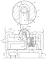
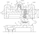
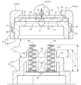
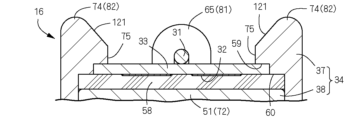
- FIG. 8 is a vertical cross-sectional view of the essential parts of the discharge device according to the first embodiment of the present invention, and is a cross-sectional view taken along the line AA in FIG. 7;
- Fig. 2 is a longitudinal front view schematically showing an ozonizer equipped with the discharge device;
- 3 is a block diagram showing the control system of the ozonizer;
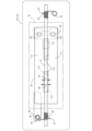
- FIG. It is a perspective view of the same discharge device. It is an exploded perspective view of the same discharge device.
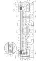
- FIG. 3 is a perspective view of a discharge portion and a base portion that constitute the same discharge device; It is a vertical front view of the same discharge device.
- FIG. 8 is a cross-sectional view taken along the line BB in FIG.
- FIG. 7; 4 is a longitudinal side view of constituent members of the discharge section;
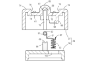
- FIG. 8 is a cross-sectional view of the separated discharge portion and base portion taken along the line AA in FIG. 7;
- FIG. 8 is a sectional view taken along line CC in FIG. 7;
- FIG. 8 is a cross-sectional view of the separated discharge portion and base portion taken along the line CC in FIG. 7; It is a top view of a base part and a discharge part turned over.
- FIG. 2 is a plan view of an electrode pair that constitutes a discharge section;
- FIG. 5 is a side view schematically showing a discharge device according to a second embodiment of the invention; It is a front view which shows the same electric discharge apparatus typically.
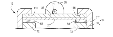
- FIG. 11 is a vertical cross-sectional view of a main part of a discharge device according to a third embodiment of the present invention; It is a figure which shows the electrode pair of the discharge device which concerns on 4th Embodiment of this invention.
- FIG. 10 is a diagram showing an electrode pair of a discharge device according to a fifth embodiment of the present invention; It is a figure which shows the electricity supply structure of the discharge device which concerns on 6th Embodiment of this invention. It is a figure which shows the electricity supply structure of the discharge device which concerns on 7th Embodiment of this invention.
- FIG. 10 is a diagram showing an electrode pair of a discharge device according to a fifth embodiment of the present invention. It is a figure which shows the electricity supply structure of the discharge device which concerns on 6th Embodiment of this invention. It is a figure which shows the electricity supply structure of the discharge device which concerns on 7th Embodiment of this invention.
- FIG. 11 is a vertical cross-sectional view of a main part of a discharge device according to an eighth embodiment of the present invention
- FIG. 21 is a vertical cross-sectional view of a main part of a discharge device according to a ninth embodiment of the present invention
- It is a figure which shows the electrode support structure of the discharge device based on 10th Embodiment of this invention.
- FIG. 20 is a vertical cross-sectional view of a main part of a discharge device according to an eleventh embodiment of the present invention
- FIG. 21 is a plan view of a discharge device according to a twelfth embodiment of the present invention
- FIG. 21 is a vertical cross-sectional view of a main part of a discharge device according to a thirteenth embodiment of the present invention
- FIG. 20 is a front view schematically showing a discharge device according to a fourteenth embodiment of the present invention
- FIG. 21 is a front view schematically showing a discharge device according to a fifteenth embodiment of the present invention.
- FIGS. 1 to 14 show a first embodiment of a discharge device according to the present invention.
- the discharge device of the present embodiment is incorporated in a desktop ozonizer (ozone generator) and plays a role of generating ozone by discharging in the air.
- Front and back, left and right, and up and down in this embodiment follow the crossed arrows shown in FIGS. The same applies to the second embodiment and subsequent embodiments.
- a casing 2 serving as a base of the ozonizer 1 is composed of a main case 3 occupying the majority of the casing and a sub case 4 detachably joined to the upper surface of the main case 3. 4, a substantially L-shaped air passage 5 is formed in the casing 2.
- a discharge device 6 for generating ozone by electric discharge a blower fan 7 for discharging the generated ozone from the air passage 5, and the like are provided.
- a suction port 8 of the air passage 5 is provided on the right side wall of the main case 3 , and a blower fan 7 is arranged facing the suction port 8 .
- the left part of the upper wall of the sub-case 4 has an inclined surface that slopes down from right to left, and the outlet 9 of the air passage 5 is provided on this inclined surface.
- the blower fan 7 forms a leftward airflow in the air path 5 from the suction port 8 toward the blowout port 9 and discharges air containing ozone from the blowout port 9 .
- the air passage 5 extends from the suction port 8 (upstream side) to the blowout port 9 (downstream side), and is formed by joining the upper and lower sides of the main case 3 and the upper and lower portions 11 formed only by the main case 3 . and a downstream portion 13 formed only by the sub case 4 .
- the blower fan 7 is arranged in the upstream section 11 together with a fan motor 14 as a drive source, and the discharge device 6 is arranged in the midstream section 12 .
- the discharge device 6 comprises a lower base portion 15 and an upper discharge portion 16.
- the base portion 15 is fixed to the lower half portion of the midstream portion 12, that is, to the main case 3, and the discharge portion 16 is detachably attached to the base portion 15. is installed.
- the base portion 15 is provided with a mounting detection portion 17 (see FIG. 3) for detecting whether or not the discharge portion 16 is mounted. Details of the discharge device 6 will be described later.
- the lower half of the midstream section 12 is partitioned by the main case 3 , while the upper half is partitioned by the sub case 4 . Therefore, when the sub case 4 is separated from the main case 3, the upper surface of the discharge device 6 is exposed and maintenance of the discharge device 6 can be performed. Specifically, for example, the surface of the discharge portion 16 can be cleaned after the discharge portion 16 is separated from the base portion 15 .
- a safety switch 18 for mechanically detecting whether or not the sub case 4 is joined is provided on the joint surface of the main case 3 with the sub case 4 .
- the main case 3 incorporates a control section 21 that controls the entire ozonizer 1 and a booster circuit (transformer) 22 .
- the main case 3 is also connected to a power supply unit 23 (see FIG. 3) such as a commercial power supply via a power cord, and a power switch 24 for turning on the power is provided on the surface (left side) of the main case 3.
- the booster circuit 22 boosts the AC voltage of, for example, 100 V supplied from the power supply unit 23 to several kV and applies the high voltage to the discharge device 6 .
- the main case 3 also incorporates a switching power supply (not shown) that converts the AC voltage supplied from the power supply unit 23 into a DC voltage of a predetermined value (eg, 5V, 12V, 24V, etc.).
- This DC voltage serves as a drive source for the IC of the control unit 21 and the fan motor 14 .
- the booster circuit 22 may boost the DC voltage output from the switching power supply and apply it to the discharge device 6 .
- the power supply unit 23 may be a power adapter that outputs a DC voltage, and in that case also, the booster circuit 22 boosts the DC voltage and applies it to the discharge device 6 .
- the control unit 21 When the power switch 24 is turned on by the user, the control unit 21 first checks the presence or absence of the discharge unit 16 and the sub case 4 based on the outputs of the attachment detection unit 17 and the safety switch 18 . After confirming that the discharge section 16 is attached to the base section 15 and that the sub case 4 is joined to the main case 3 , the control section 21 connects the power supply section 23 to the fan motor 14 and the booster circuit 22 . Start energizing. When power is supplied to the fan motor 14 and the booster circuit 22, the blower fan 7 and the discharge device 6 are driven. As a result, an air current is formed in the air passage 5 from the suction port 8 toward the blowout port 9 , and air containing ozone generated around the discharge device 6 is blown out from the blowout port 9 .
- control section 21 When the separation of the sub case 4 or the discharge section 16 is confirmed, the control section 21 immediately interrupts the energization to the booster circuit 22 and the like. It is possible to reliably prevent an electric shock accident in which the user touches the electrodes 31 and 32 (described later) and the terminals 85 and 86 (described later) in the closed state.
- the controller 21 When starting to supply power to the fan motor 14 and the booster circuit 22, the controller 21 lights the notification means 27, which is a lamp, in green, for example, so as to notify the user that the ozonizer 1 is being driven. good too. Further, when the presence of the discharge portion 16 and the sub case 4 cannot be confirmed, the notification means 27 may be illuminated in red, for example, to inform the user of this fact.
- a photodetector 28 is provided near the discharge device 6 in the air passage 5 to detect the blue light emitted by the discharge section 16 during discharge.
- the light detection unit 28 include a color sensor using a photodiode, a camera, and the like.
- the control unit 21 can determine the degree of contamination (accumulation of dust and the like) of the discharge unit 16 based on the amount of blue light detected by the light detection unit 28 . If it is determined that the amount of light is less than a predetermined value, that is, the degree of contamination is high, the controller 21 lights the notification means 27 in, for example, yellow to prompt the user to clean the discharge device 6 early.
- the discharge device 6 is composed of a base portion 15 fixed inside the air passage 5 and a discharge portion 16 detachably mounted on the upper side of the base portion 15 . If the discharge section 16 is detachable from the base section 15, the discharge section 16, which is relatively easily soiled, can be easily cleaned while being separated from the base section 15. FIG. Moreover, when the discharge unit 16 breaks down, only the discharge unit 16 can be replaced, and the repair cost can be reduced compared to the case where the entire discharge device 6 including the base unit 15 is replaced. There is also an advantage that an operator can easily attach the discharge section 16 to the base section 15 in the manufacturing line of the discharge device 6 or the ozonizer 1 . The entire discharge portion 16 is rotationally symmetrical about the vertical axis, strictly speaking, two-fold symmetrical. That is, when the orientation of the discharge section 16 shown in FIG. 16 can be properly attached to the base portion 15 in either the first posture or the second posture.
- the discharge section 16 is composed of a first electrode 31 and a second electrode 32 that face each other vertically, a dielectric 33 interposed between the electrodes 31 and 32, a discharge case 34 that supports them, and the like.
- the first electrode 31 on the upper side is formed in the shape of a round bar extending straight from side to side and is in contact with the upper surface of the dielectric 33 .
- the second electrode 32 on the lower side is composed of a film formed on the lower surface of the dielectric 33 by a film forming method such as sputtering.
- Each of the electrodes 31 and 32 can be made of any metal or alloy such as silver, copper, or stainless steel.
- the first electrode 31 and the second electrode 32 are made of titanium, which has excellent corrosion resistance.
- the diameter of the round bar-shaped first electrode 31 was set to 1 mm, and the thickness of the film-shaped second electrode 32 was set to 50 to 150 nm.
- the discharge section 16 can be made compact with a small vertical dimension.
- the dielectric 33 is made of an insulating material such as glass, and is formed in the shape of a horizontally elongated rectangular plate. Specific examples of insulating glass include borosilicate glass and quartz glass. In this embodiment, the dielectric 33 has a thickness of 0.7 mm.
- the discharge case 34 is made of insulating plastic, and has a rectangular discharge opening 35 formed on its upper surface to expose the first electrode 31 and the dielectric 33 upward.
- the discharge case 34 is composed of a rectangular frame-shaped outer case 37 having top and bottom openings and a rectangular plate-like inner case 38 opening downward.
- An inner case 38 is fitted from the inside.
- the upper opening of the outer case 37 functions as the discharge opening 35
- the lower opening of the case 37 is closed with the inner case 38 .
- An engagement structure consisting of a protrusion 39 and a recess 40 is provided on each of the front and rear walls of both cases 37 and 38 (see FIG. 11).
- the projections 39 are provided on the outer surfaces of the front and rear walls of the inner case 38
- the recesses 40 are provided on the inner surfaces of the front and rear walls of the outer case 37, but this arrangement may of course be reversed.
- Engagement structures can also be provided on the left and right walls of both cases 37 and 38 .
- a base case 42 serving as the base of the base portion 15 is made of an insulating plastic molded product like the outer case 37 and the inner case 38 of the discharge case 34, and has a relatively small upper step portion 43. and a large lower step portion 44 integrally formed in a rectangular stepped platform shape.
- a lower portion 44 of the base case 42 is fixed to the main case 3 with a plurality of screws 45 .
- a downward mounting recess 46 is provided that receives the upper step portion 43 and surrounds it from the front, rear, left and right.
- a downward engaging protrusion 47 is formed.
- a recess 48 is recessed.
- the engaging convex portion 47 is a flat protrusion having a rectangular cross section, and the engaging concave portion 48 is a rectangular flat concave portion slightly larger than the engaging convex portion 47 .
- the upper step portion 43 of the base case 42 is fitted into the inner case 38 of the discharge case 34 from below and engaged with the attachment recess 46, as shown in FIGS.
- the engagement protrusion 47 engages with the engagement recess 48 .
- the planar shape of the engaging projection 47 and the engaging recess 48 is not limited to a rectangle.
- the discharge portion 16 can be restricted from shifting and rotating. It is also possible to provide a plurality of sets of engaging projections 47 and engaging recesses 48, in which case displacement and rotation of the discharge portion 16 can be restricted regardless of the planar shapes of both 47 and 48.
- the horizontal ceiling walls of the inner case 38 and the upper stage section 43 face each other vertically.
- the portion of the top wall of the inner case 38 that faces the upper stepped portion 43 (excluding the left and right end portions)
- the top wall of the upper stepped portion 43 will be referred to as a lower facing wall 52 .
- These opposing walls 51 and 52 are provided with attachment holding means for regulating the unintentional upward separation of the discharge section 16 from the base section 15 and holding the discharge section 16 in the mounted state.
- This mounting and holding means is composed of a rectangular parallelepiped magnet 53 attached to the upper facing wall 51 of the inner case 38 and a rectangular plate-shaped magnetic body 54 attached to the lower facing wall 52 of the upper step portion 43 .
- an upper accommodation recess 55 that opens upward and accommodates the magnet 53
- the upper accommodation recess 55 opens downward.
- a lower housing recess 56 for housing the magnetic body 54 is formed.
- the upper surface of the magnet 53 accommodated in the upper accommodation recess 55 is substantially flush with the upper surface of the upper facing wall 51 .
- the mounting detection unit 17 which is a magnetic sensor, is fixed to the lower surface of the magnetic body 54 , and the mounting detection unit 17 is housed in the lower housing recess 56 together with the magnetic body 54 .
- the magnet 53 constituting the attachment holding means is arranged on the back side (upper side) of the engaging projection 47 with the upper facing wall 51 interposed therebetween, and the magnetic body 54 is arranged with the engaging recess 48 interposing the lower facing wall 52 therebetween. is located on the back side (lower side) of the Therefore, when the engaging convex portion 47 is engaged with the engaging concave portion 48, the magnet 53 is positioned directly above the magnetic body 54, and the magnetic body 54 is reliably attracted to the magnet 53. . Due to this adsorption force, unintended upward separation of the discharge portion 16 from the base portion 15 can be regulated.
- the attachment detection unit 17 positioned below the magnetic body 54 outputs a signal to the control unit 21 upon detecting the magnetic field generated by the magnet 53 .
- the control unit 21 can determine that the discharge unit 16 is attached to the base unit 15 .
- the impact when the discharge device 6 receives an external force is less likely to reach the magnetic body 54 than when the magnetic body 54 is arranged on the lower part 44. 16 becomes difficult to come off from the base part 15. ⁇
- the magnet 53 housed in the upper housing recess 55 is surrounded by the walls of the upper housing recess 55 on all four sides, front, back, left, and right, so that it is restricted from shifting in the horizontal direction and from rotating around the vertical axis.
- the magnetic body 54 accommodated in the lower accommodating recess 56 is also restricted from shifting in the horizontal direction and from rotating about the vertical axis by being surrounded by the walls of the lower accommodating recess 56 on all four sides.
- the planar shape of the magnet 53 and the magnetic body 54 is not limited to a rectangle. , the displacement and rotation of the magnetic body 54 can be restricted.
- the arrangement of the magnet 53 and the magnetic body 54 may be reversed. This is convenient when drying the discharge section 16 after washing with water.
- the second electrode 32 and the dielectric 33 are adhered and fixed to the upper surface of the upper facing wall 51 (and the magnet 53) of the inner case 38 via a cushion material 58 made of double-sided tape.
- the cushion material 58 is formed in a rectangular shape that is one size larger than the dielectric 33 , and the second electrode 32 is sandwiched between the dielectric 33 and the cushion material 58 from above and below.
- the peripheral portion of the cushion material 58 is elastically deformed and adheres to the dielectric 33 .
- the upper ends of the front and rear walls of the outer case 37 protrude inward toward the rod-like first electrode 31, and the lower surfaces of the protruding portions receive the front and rear edges of the dielectric 33.
- An upper inner receiving portion 59 and a lower outer receiving portion 60 for receiving the front and rear edges of the cushion material 58 are formed stepwise.
- the dielectric 33 is sandwiched from above and below by the outer case 37 (inner receiving portion 59) and the inner case 38 (upper facing wall 51).
- the cushion material 58 positioned between the dielectric 33 and the inner case 38 is elastically deformed by being pushed by the dielectric 33 and the outer receiving portion 60 from above and by the inner case 38 from below, and the thickness dimension of the dielectric 33 and the like are elastically deformed.
- Absorb design tolerances of The dielectric 33 is positioned in the front-rear direction by a vertical wall between the inner receiving portion 59 and the outer receiving portion 60 of the outer case 37 .
- a pair of left and right upper walls 61 forming right and left edges of the discharge opening 35 are provided on the upper part of the outer case 37.
- the body 33 is positioned in the left-right direction.
- the rod-shaped first electrode 31 is supported by a pair of left and right electrode support structures 64 provided on the discharge case 34 .
- the electrode support structure 64 includes upper support portions 65 provided on both left and right sides of the discharge opening 35 in the outer case 37, and lower support portions projecting from both left and right ends of the ceiling wall of the inner case 38 (left and right sides of the upper facing wall 51). 66.
- the upper support portion 65 is formed in the front-rear center of each upper wall 61 of the outer case 37 so as to extend laterally in a tunnel shape.
- An upper semi-circular receiving groove 67 for receiving the upper half of the first electrode 31 is recessed in the inner surface of the upper support portion 65 .
- Relief recesses 68 are formed to receive electrode connection portions 90 of body 87 (see FIG. 7).
- each receiving groove 67 (the tip side of the first electrode 31) is directly above a lower semicircular receiving portion 69 (see FIG. 9) recessed in the tip surface of the lower support portion 66. , and both 67 and 69 cooperate to sandwich the first electrode 31 from above and below.
- An introduction groove 70 (see FIG. 9) extending downward continuously from the receiving groove 67 is formed in the inner surface of the left and right walls of the outer case 37 .
- the electrode support structure 64 of this embodiment is composed of an upper support portion 65 (receiving groove 67) and a lower support portion 66 (receiving portion 69) that are in close contact with the peripheral surface of the first electrode 31.
- the electrode support structure 64 may allow the first electrode 31 to move slightly.
- the hole surrounded by the receiving groove 67 and the receiving portion 69 can be formed as an oval in the vertical direction, and the vertical movement of the first electrode 31 can be allowed within the range of its length.
- the first electrode 31 is urged downward by a first conductor 87 (to be described later) and comes into close contact with the upper surface of the dielectric 33 .
- the electrode support structure 64 only needs to have the minimum function of supporting the first electrode 31 .
- the electrode support structure 64 may be arranged only at one end of the first electrode 31 to support it in a cantilever manner. According to this, one of the left and right electrode support structures 64 can be omitted, and the structure of the discharge case 34 can be simplified by that amount, which contributes to cost reduction of the discharge device 6 .
- the first electrode 31 in this case can be formed in a straight rod shape, a zigzag shape, a crank shape, a meandering shape, a spiral shape, or the like.
- the electrode unit 71 is positioned within the discharge case 34 together with the cushion material 58, the outer case 37 and the inner case 38. are sandwiched from above and below. Specifically, the first electrode 31 constituting the upper portion of the electrode unit 71 is supported from above by the upper support portion 65 of the outer case 37, and the second electrode 32 and the dielectric 33 constituting the lower portion of the electrode unit 71 , and is supported from below by the upper facing wall 51 of the inner case 38 via a cushion material 58 .
- the upper facing wall 51 constitutes a lower receiving portion 72 that receives the surface of the dielectric 33 on the second electrode 32 side, or a lower receiving portion 72 that receives the second electrode 32 from the back side of the dielectric 33 .
- first electrode 31 it is not essential for the first electrode 31 to abut on the upper surface of the dielectric 33, and both 31 and 33 may vertically face each other with a small gap therebetween.
- a support structure that supports the dielectric 33 (and the second electrode 32 ) at a position spaced downward from the first electrode 31 can be provided separately from the electrode support structure 64 .
- a spacer or bush can be interposed between the first electrode 31 and the dielectric 33 .
- the first electrode 31 may be urged downward by a first conductor 87, which will be described later, and pressed against a spacer or the like.
- white dust containing nitrate as a main component may accumulate on the upper surface of the discharge section 16, particularly on the surfaces of the first electrode 31 and the dielectric 33.
- the nitrogen, oxygen and moisture in the air can react to form nitric acid, which causes nitrate or dust deposition. Since this dust interferes with the discharge, it is desirable to remove it periodically.
- a cleaning brush can be used in addition to washing with water.
- the moving direction of the cleaning brush is desirably the horizontal direction that coincides with the extending direction of the first electrode 31, so that the bristles of the cleaning brush are moved from one end of the first electrode 31 toward the other end,
- the surfaces of the first electrode 31 and the dielectric 33 can be cleaned simultaneously.
- the outer case 37 of the discharge case 34 is The upper surface is provided with upward grooves 73 adjacent to the left and right sides of the dielectric 33 (discharge opening 35).
- the top surface of dielectric 33 and the bottom surface of groove 73 are flush with each other. Therefore, the dust can be avoided from being caught between the dielectric 33 and the groove 73, and can be easily swept out without any residue.
- a pair of protrusions 74 extending parallel to the first electrode 31 are provided on the upper surface of the outer case 37 of the discharge case 34 with the dielectric 33 (discharge opening 35) therebetween.
- Side surfaces facing the dielectric 33 at the left-right central portion of each protrusion 74 constitute a center guide surface 75, and side surfaces continuing to the left and right sides of the center guide surface 75 constitute end guide surfaces 76 that partition the groove portion 73.
- the groove portion 73 in this embodiment is defined by the ridge 74 (end guide surface 76), the upper wall 61, and the upper support portion 65, and the groove portion 73 is formed on both front and rear sides of the left and right upper support portions 65.
- the center guide surface 75 of each projection 74 guides the bristles of the cleaning brush in the left-right direction and retains the bristles on the surface of the dielectric 33, contributing to accurate cleaning of the surface.
- the left and right end guide surfaces 76 are smoothly continuous with the center guide surface 75 . These guide surfaces 75 and 76 allow the bristles of the cleaning brush to be smoothly guided from one groove 73 to the surface of the dielectric 33 and smoothly guided from the surface to the other groove 73 .
- a user can, for example, introduce a cleaning brush through the left groove 73 and move the brush straight to the right to catch dust and sweep it out of the right groove 73 . When this operation is performed on the front side and the rear side of the first electrode 31 respectively, dust removal, ie, cleaning, is completed.
- the cleaning work described above is performed with the discharge section 16 separated from the base section 15 .
- the left and right upper support portions 65 function as knobs.
- marks 79 made of protrusions are provided at the front and rear centers of the left and right outer surfaces of the case body 34 (outer case 37).
- the portion 16 can be separated from the base portion 15 by picking it up with two fingers from both left and right sides and pulling it up.
- the lateral dimension of the discharge portion 16 (discharge case 34) according to the present embodiment is approximately 45 mm, and the longitudinal dimension thereof is approximately 16 mm.
- the upper support portion 65 that protrudes significantly upward from the first electrode 31 As a knob, it is possible to prevent the user from touching the first electrode 31 and the dielectric 33 and getting sebum and the like from adhering to them.
- the mark 79 indicates that the upper support portion 65 is a knob, the user may pick up a portion other than the upper support portion 65, such as the front and rear walls of the case body 34, and accidentally touch the first electrode 31 or the dielectric 33. can often be prevented.
- the mark 79 may be a mark printed on the case main body 34, but by using this as a projection, the mark 79 can also function as a non-slip, allowing the user to firmly hold the discharge case 34. can.
- the upper support portion 65 also serves as a first protection portion 81 (protection portion 81) that protects the first electrode 31 from a drop impact.
- a pair of protrusions 74 provided on the front and rear sides of the outer case 37 also protrude upwards from the first electrode 31, although the projection dimension is smaller than that of the first protection portion 81 (upper support portion 65) (see FIG. 3). 7), it can hit the floor or the like first, like the first protection part 81 .
- the ridge 74 constitutes a second protection portion 82 (protection portion 82) that protects the first electrode 31 from a drop impact.
- the base portion 15 is provided with a first terminal 85 and a second terminal 86 to which an AC voltage of several kV is supplied from the booster circuit 22.
- the second electrode 32 is electrically connected to a second terminal 86 via a second conductor 88 . That is, the booster circuit 22 applies a high AC voltage to the first electrode 31 and the second electrode 32 via the terminals 85 and 86 and the conductors 87 and 88 .
- the terminals 85 and 86 and the conductors 87 and 88 are made of metal such as gold-plated stainless steel.
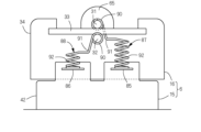
- the first conductor 87 is formed by bending a single conductor wire (metal wire).
- a terminal connection portion 92 is integrally provided.
- the electrode connecting portion 90 is formed in a coil shape with the horizontal direction as the axial direction, and is wound around the peripheral surface of the first electrode 31 so as to be in close contact (see FIG. 7).
- the winding portion 91 is formed in an L shape having a vertical portion and a horizontal portion when viewed from the side, and urges downward one end of the electrode connecting portion 90 that is continuous with the vertical portion. By pulling one end of the electrode connection portion 90 downward with the winding portion 91 , the adhesion of the electrode connection portion 90 to the peripheral surface of the first electrode 31 can be enhanced.
- the seam portion 91 exhibits springiness in this manner because the horizontal portion of the seam portion 91 is received by the lower surface of the upper wall 61 of the outer case 37 , that is, the seat portion 94 .
- the diameter R2 of the inner peripheral surface in the natural state before the electrode connection portion 90 is wound around the first electrode 31 is slightly smaller than the diameter R1 of the first electrode 31 (R2 ⁇ R1).
- the electrode connection portion 90 is pushed from the inside by the first electrode 31 and wound around the electrode 31 in a state of being expanded in diameter. According to this, the electrode connecting portion 90 is brought into close contact over the entire circumferential length of the first electrode 31 so that both 31 and 90 are brought into a point contact state in which they are in contact only at one point or several points in the circumferential direction. can be reliably prevented.
- the electrode connection portion 90 when the electrode connection portion 90 is tightly attached to the first electrode 31, the electrode connection portion 90 can be connected to the first electrode without taking time and effort such as fixing the tip of the electrode connection portion 90 to the first electrode 31 by welding. It is possible to reliably prevent unraveling from 31 (of course, it is also possible to secure by welding for completeness). These functions and effects are further enhanced by pulling the electrode connecting portion 90 downward with the seam tightening portion 91, but even if the seam tightening portion 91 is omitted, a sufficiently high function and effect can be obtained.
- the cross-sectional shape of the first electrode 31 is not limited to a perfect circle, and may be other shapes such as an ellipse, an oval, a regular polygon, a rhombus, a cross, and a D-shape.
- the electrode connection portion 90 is formed in a shape that corresponds to the first electrode 31 and allows close contact (line contact) with the peripheral surface thereof. Only the end of the first electrode 31 around which the electrode connecting portion 90 is wound may be D-cut or the like to form the various non-circular cross sections described above.
- the first electrode 31 may be formed in the shape of a hollow round pipe or square pipe.
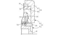
- a terminal connection portion 92 that continues to the lower side of the seam portion 91 is formed in the shape of a compression coil spring whose axial direction is the vertical direction. 1, the lower end of the terminal connection portion 92 is in elastic contact with the upper surface of the first terminal 85, and the first conductor 87 is electrically connected to the first terminal 85. be. At this time, the terminal connecting portion 92 is vertically compressed, and its upper end is received by the seat portion 94 in the same manner as the horizontal portion of the winding portion 91 .
- the lower end of the terminal connection portion 92 that is, the first contact 95 is formed in an annular shape.
- the number of parts can be reduced, and the labor and cost of assembly during manufacturing can be reduced.
- the terminal connection portion 92 in the compressed state is elastically brought into close contact with the first terminal 85, the electrical connection between the two terminals 85 and 92 is stable and reliable. , and the design tolerance of the vertical dimensions of the base case 42 and the like can be absorbed.
- the repulsive force in the vertical direction exerted by the terminal connection portion 92 in the compressed state is sufficiently smaller than the attraction force between the magnet 53 and the magnetic body 54 that constitute the mounting and holding means described above.
- the discharge portion 16 is not separated from the base portion 15 only by force. However, since part of the attraction force of the mounting and holding means is offset by the repulsive force of the terminal connection portion 92, the user should separate the discharge portion 16 from the base portion 15 with a lighter force when cleaning the discharge portion 16 or the like. can be done.
- the terminal connection portion 92 is separated from the vertical portion in the horizontal direction (front-rear direction) via the horizontal portion of the seam portion 91 .
- the downward biasing force acting on the electrode connection portion 90 from the vertical portion of the winding portion 91 is prevented from being canceled by the repulsive force of the terminal connection portion 92, and the electrode connection portion 90 is can be brought into close contact with the peripheral surface of the first electrode 31 .
- a substantially cylindrical storage boss 99 is provided downwardly to define a storage hole 98 for the terminal connection portion 92 of the first conductor 87 so as to surround the seat portion 94. be done.
- the upper half of the terminal connection portion 92 is accommodated in the accommodation hole 98, and by surrounding the upper half of the terminal connection portion 92 with the accommodation boss 99, the upper half is protected from external forces. Damage such as deformation can be prevented.
- a vertical groove is formed in a part of the peripheral wall of the housing boss 99 to allow the horizontal portion of the winding portion 91 to pass therethrough.
- a ceiling wall of the inner case 38 is provided with an insertion hole 100 through which the storage boss 99 and the terminal connection portion 92 are inserted.
- the peripheral surface of the insertion hole 100 is close to and surrounds the outer peripheral surface of the tip (lower end) of the storage boss 99 .
- the insertion hole 100 can protect the tip of the storage boss 99 from external force and prevent damage such as deformation.
- a terminal block 101 projects from the upper surface of the lower portion 44 of the base case 42 so as to face the housing boss 99 when the discharge portion 16 is mounted.
- the terminal block 101 is formed in the shape of a rectangular tube that opens upward, and the spring receiving portion 96 of the first terminal 85 is arranged inside.
- the first conducting body 87 moves integrally with the discharge portion 16 , and the terminal connection portion 92 is separated from the first terminal 85 so as to be in a compressed state.
- the natural length L1 With respect to this natural length L1, the depth D1 of the storage hole 98 (the height of the storage boss 99) is set to a dimension that satisfies the inequality (L1/2 ⁇ D1 ⁇ L1). If the depth D1 of the housing hole 98 is larger than half of the natural length L1 of the terminal connecting portion 92, that is, if the upper half of the terminal connecting portion 92 is housed in the housing hole 98, it is relatively easy to buckle.
- the buckling can be prevented accurately.
- the depth D1 is set to half the natural length L1 of the terminal connection portion 92.
- the lower end of the terminal connection portion 92 in the natural length L1 is located above the lower end of the discharge case 34, and according to this, when the discharge portion 16 separated from the base portion 15 is placed on a desk or the like, the terminal By preventing the connecting part 92 from touching the tabletop, that is, from being compressed, deterioration of the terminal connecting part 92 can be suppressed and the life of the terminal connecting part 92 can be extended.
- each of the second current-carrying bodies 88 is made of one conductor (metal wire) and is formed in the shape of a compression coil spring whose axial direction is the vertical direction.
- the first conductor 87 is connected to the first electrode 31 of the discharge section 16 and is separable from the first terminal 85 of the base section 15
- the second conductor 88 is connected to the first terminal 85 of the base section 15 . It is connected to two terminals 86 and is separable from the second electrode 32 of the discharge section 16 .
- each second conductor 88 is vertically compressed and its upper end is elastically brought into close contact with the lower surface of the second electrode 32 .
- cylindrical storage bosses 105 and 106 that define the storage hole 104 for the second conductor 88 are protruded upward and downward.
- the lower half of the second conductor 88 excluding the upper end is accommodated in the housing hole 104.
- Damage such as deformation can be prevented by protecting the majority portion from external force.
- a protruding end (lower end) of the lower housing boss 106 abuts on the second terminal 86 and surrounds the connecting (crimped) portion between the second terminal 86 and the second conductor 88 .
- the tip (upper end) of the upper housing boss 105 is not in contact with the lower surface of the second electrode 32 and is close to the lower surface of the second electrode 32 when the discharge section 16 is attached to the base section 15 . Also, at this time, the upper end of the second conductor 88 protrudes from the tip of the upper housing boss 105 , ie, the upper opening of the housing hole 104 , and comes into close contact with the lower surface of the second electrode 32 .
- the upper facing wall 51 and the cushion material 58 of the inner case 38 of the discharge section 16 are provided with insertion holes 107 and 108 through which the upper housing boss 105 is inserted.
- the inner peripheral surfaces of the insertion holes 107 and 108 are close to and surround the outer peripheral surface of the upper housing boss 105 .
- These insertion holes 107 and 108 prevent the upper housing boss 105 from being displaced in the horizontal direction with respect to the second electrode 32 , thereby ensuring that the second conductor 88 is properly positioned on the second electrode 32 . can be abutted.
- the outer peripheral surface of the tip portion of the upper storage boss 105 is tapered upward, and the lower portion of the insertion hole 107 of the upper facing wall 51 through which the boss 105 is inserted is tapered downward. ing. These tapered surfaces allow the upper housing boss 105 to be easily guided into the insertion hole 107 when the discharge section 16 is attached to the base section 15 .
- the depth D2 of the storage hole 104 is set to a dimension that satisfies the inequality (L2/2 ⁇ D2 ⁇ L2). If the depth D2 of the housing hole 104 is larger than half of the natural length L2 of the second conductor 88, that is, if the lower half of the second conductor 88 is housed in the housing hole 104, relatively By surrounding the vertical center of the second conductor 88, which tends to buckle, with the storage hole 104, the buckling can be reliably prevented.
- the depth D2 is 2 of the natural length L2 of the second conductor 88.
- the height T of the upper housing boss 105 is set smaller than half the depth D2 of the housing hole 104 (T ⁇ D2/2). According to this, the amount of protrusion of the upper housing boss 105 from the lower facing wall 52 is reduced, and the deformation and breakage of the upper housing boss 105 when receiving an external force can be well prevented.
- the electrical connection between both 32 and 88 is stable and reliable.
- Design tolerances such as the top and bottom thickness of the dielectric 33 can be absorbed.
- the second electrode 32 By supporting the back side of the surface of the second electrode 32 that receives the second conductor 88 , i.e., the upper surface, with the dielectric 33 made of a glass plate, the second electrode 32 can be reinforced and prevented from being deformed. Since the dielectric 33 is sufficiently thicker than the second electrode 32, the second electrode 32 can be firmly reinforced. The upward elastic force acting on the dielectric 33 from the second conductor 88 via the second electrode 32 is firmly received by the inner receiving portion 59 of the outer case 37 .
- the second electrode 32 and the second terminal 86 are electrically connected by a pair of second conductors 88, a connection failure may occur between one of the second conductors 88 and the second electrode 32 or the second terminal 86.
- the spring constant of the pair of second conductors 88 is the same, and according to this, the elastic force acting on the second electrode 32 is made uniform without being biased toward the front or back, and both of the second conductors 88 are arranged in the same direction. It can be brought into close contact with the two electrodes 32 to stabilize the electrical connection therebetween.
- the upward elastic force acting on the second electrode 32 from each second conductor 88 also acts on the first electrode 31 via the dielectric 33 .
- the synergistic effect of this upward elastic force and the elastic force of the winding part 91 of the first conductor 87 pulling the one end of the electrode connection part 90 downward allows the electrode connection part 90 to adhere closely to the peripheral surface of the first electrode 31 . more improved.
- the first terminal 85 (spring receiving portion 96) is arranged only at one left and right end (here, the left end) of the base portion 15, whereas the first conductor 87 is located at the first electrode 31. are located on the left and right ends of the Only one of them, the first conducting member 87 , is brought into close contact with the first terminal 85 when the discharge portion 16 is attached, and contributes to conducting electricity from the first terminal 85 to the first electrode 31 .
- the pair of second conductors 88 are arranged only on one left and right side (right side in this case) of the base portion 15, the insertion holes 107 and 108 for allowing them to pass through are arranged on both left and right sides of the discharge portion 16. ing. Only one of these insertion holes 107 and 108 allows the second conductor 88 to pass therethrough when the discharge section 16 is attached, and contributes to energization from the second terminal 86 to the second electrode 32 .
- the reason why the first conductors 87 are arranged on both the left and right sides of the first electrode 31 and the insertion holes 107 and 108 are arranged on both the left and right sides of the discharge section 16 is that the discharge section 16 is arranged in two directions around the vertical axis as described above. This is due to the rotational symmetry.
- the discharge portion 16 is attached to the base portion 15 in the first posture, the first conductor 87 on the left side and the insertion holes 107 and 108 on the right side exhibit their functions, and when the discharge portion 16 is attached in the second posture. , the first conductor 87 on the right side and the insertion holes 107 and 108 on the left side exhibit their functions.
- the electrodes 31 and 32 and the terminals 85 and 86 are electrically connected to the electrodes 31 and 32 and the terminals 85 and 86 through the conductors 87 and 88 regardless of whether the discharge section 16 having two rotational symmetry is attached to the base section 15 in the first posture or the second posture.
- This allows a user-friendly discharge device 6 in which the user does not have to worry about the orientation of the discharge section 16 when the discharge section 16 is attached.
- the terminal block 101 or the like is not provided at the diagonal position of the first terminal 85 (spring receiving portion 96) in the plan view of the base case 42. Therefore, when the terminal connection portion 92 of one of the first conductors 87 is brought into close contact with the first terminal 85, the terminal connection portion 92 of the other first conductor 87 is extended to its natural length and attached to the lower stage of the base case 42. It faces the upper surface of the part 44 . In other words, it is possible to prevent the terminal connection portion 92 from being compressed, thereby suppressing its deterioration and extending its life. Further, the position where the second electrode 32 is brought into close contact with the second conductor 88 differs between the first posture and the second posture of the discharge portion 16 . According to this, the wear of the second electrode 32 can be suppressed and the life of the second electrode 32 can be extended.
- the spring receiving portion 96 of the first terminal 85 that receives the first conductor 87 is arranged in the lower part 44 of the base case 42 , whereas the second conductor 88 extending from the second terminal 86 is located in the upper part of the case 42 . It is arranged in the portion 43 . That is, the pair of terminals 85 and 86 and the conductors 87 and 88 are arranged separately in the upper and lower step portions 43 and 44 of the base case 42 .
- the second electrode 32 is formed in a horizontally long rectangular shape that is one size smaller than the dielectric 33 .
- An extending air gap 110 is provided. That is, the second electrode 32 is divided into a first region 111 on the front side and a second region 112 on the rear side with the air gap 110 as a boundary, and the two regions 111 and 112 are separated only by the bridging portions 113 at three locations on the left and right. Contiguous.
- the bridging portions 113 are arranged at the left-right center and both ends of the second electrode 32 .
- Each bridging portion 113 is formed (film-formed) at the same time as the first region 111 and the second region 112, but may be formed separately from these regions 111 and 112.
- the entire second electrode 32 is arranged inside the periphery of the dielectric 33 , thereby reliably preventing discharge between the electrodes 31 and 32 not through the dielectric 33 . .
- the peripheral portion of the cushion material 58 is in close contact with the dielectric 33, and the peripheral portion of the second electrode 32 is formed between the dielectric 33 and the cushion material 58 over the entire circumference. is sealed between According to this, it is possible to more reliably prevent discharge from occurring between the peripheral portion of the second electrode 32 and the first electrode 31 without the dielectric 33 interposed therebetween.
- a gap 110 is provided in the front and rear center of the second electrode 32 , that is, directly below the first electrode 31 in order to increase the amount of ozone generated by performing this silent discharge over a wide range. Due to the presence of this gap 110, more charges on the surface of the dielectric 33 gather in front and behind the first electrode 31 (above the first region 111 and the second region 112) than directly under the first electrode 31. As a result, the dielectric Discharge occurs over a wide area on the surface of body 33 . In addition, the air gap 110 can prevent the discharge from concentrating directly under the first electrode 31, where white dust (nitrate), which hinders the discharge, tends to accumulate. If the discharge is generated before and after the first electrode 31 where dust accumulation is relatively small, the amount of discharge is maintained for a relatively long period of time. can be done.
- the width W1 of the first electrode 31 in the front-rear direction is 1 mm, which corresponds to its diameter, while the width W2 of the gap 110 in the same direction is set at 2 mm.
- the width W2 of the gap 110 is set to be larger than the width W1 of the first electrode 31, the amount of charge collected on the surface of the dielectric 33 just below the first electrode 31 can be reduced, and the discharge can be spread over a wider area.
- the vertical height H1 of the first electrode 31 is 1 mm, which is equal to its diameter, while the vertical thickness H2 of the dielectric 33 is set to 0.7 mm. ing.
- the thickness H2 of the dielectric 33 is set to be smaller than the height H1 of the first electrode 31, the imaginary line connecting the front and rear edges of the second electrode 32 and the first electrode 31 is moved from the vertical to the horizontal, and the dielectric 33 is The surface charge distribution can be closer to its leading and trailing edges, thereby spreading the discharge over a wider area.
- the rod-shaped first electrodes 31 can be arranged so as to be inclined in the horizontal plane, for example along the diagonal line of the discharge opening 35 . According to this, compared with the case where the first electrodes 31 are arranged straight from side to side, the entire length of the first electrodes 31 can be increased to widen the range of discharge.
- the first electrode 31 can be bent, curved or meandered, or two or more first electrodes 31 can be provided, which can also widen the discharge range. By widening the discharge range in this way, the amount of ozone generated can be increased accordingly.
- the electrode is wound around one or more turns in the circumferential direction of the first electrode 31 around one end of the first conducting body 87 responsible for energizing the rod-shaped first electrode 31 .
- a connection 90 is provided.
- the first electrode 31 and the first conductor 87 are brought into line contact, and the contact area between the two 31 and 87 can be made larger than in the conventional case.
- the contact pressure at the connection between the two 31 and 87 can be reduced, and the long-term durability of the connection can be enhanced. Even when a part of the surface of the electrode 31 or the first conductor 87 is oxidized over time, it is possible to prevent the occurrence of poor conduction and maintain the voltage applied to the first electrode 31 at a high level.
- the relative positions of the electrodes 31 and 32 may be shifted due to, for example, design tolerances of the support structure of the electrodes 31 and 32 . Even if this occurs, the discharge between the electrodes 31 and 32 can be generated without any problem. Therefore, discharge can be performed more stably.
- the winding part 91 that biases the electrode connection part 90 of the first conductor 87 away from the first electrode 31 is provided, the adhesion of the electrode connection part 90 to the peripheral surface of the first electrode 31 is improved, The electrical resistance between 31 and 87 can be reduced.
- the seam portion 91 can be used to bring the first electrode 31 into close contact with the dielectric 33, and the structure of the discharge section 16 can be simplified compared to the case where a contact means other than the seam tightening section 91 is provided.
- the discharge case 34 that accommodates both the electrodes 31 and 32 and the dielectric 33 is provided with the lower receiving portion 72 that receives the surface of the dielectric 33 on the second electrode 32 side, the urging force of the winding portion 91 can be resisted. As a result, the first electrode 31 can be firmly received by the dielectric 33 .
- the cushion material 58 When the cushion material 58 is arranged between the lower receiving portion 72 of the discharge case 34 and the dielectric 33, the repulsive force (vertical force) that the dielectric 33 receives from the lower receiving portion 72 is buffered by the cushion material 58. , deformation and breakage of the dielectric 33 can be prevented. In addition, the elastic deformation of the cushion material 58 can absorb design tolerances such as the thickness dimension of the dielectric 33 and bending.
- the electrode support structure 64 is composed of the upper support portion 65 and the lower support portion 66 that sandwich the peripheral surface of the first electrode 31 from above and below, the first electrode 31 is simply sandwiched from above and below by the upper support portion 65 and the lower support portion 66 .
- the first electrode 31 can be fixed to the discharge case 34 by a simple operation of .
- the structure of the discharge case 34 and the discharge device 6 can be simplified.
- the electrode unit 71 By sandwiching the electrode unit 71 together with the cushion material 58, the electrode unit 71 can be brought into close contact with the cushion material 58, and its movement can be well regulated. In addition, the elastic deformation of the cushion material 58 can absorb design tolerances of the electrode unit 71 and the discharge case 34 .
- the discharge section 16 including the first electrode 31 and the first conductor 87 is detachable from the base section 15 including the first terminal 85, the discharge section 16 is relatively easily soiled due to the inclusion of the first electrode 31. can be easily cleaned in a state separated from the base portion 15 . Moreover, when the discharge unit 16 breaks down, only the discharge unit 16 can be replaced, and the repair cost can be reduced compared to the case where the entire discharge device 6 including the base unit 15 is replaced. There is also an advantage that an operator can easily attach the discharge portion 16 to the base portion 15 in the manufacturing line of the discharge device 6 .
- the terminal connection portion 92 provided at the other end portion of the first conductor 87 is elastically brought into close contact with the first terminal 85 in a state where the discharge portion 16 is attached to the base portion 15, the first The electrical connection between the terminal 85 and the terminal connection portion 92, i.e., the first current-carrying body 87 is stable and reliable. Design tolerances can be absorbed.
- the first conductor 87 integrally including the electrode connection portion 90 and the terminal connection portion 92, it is possible to reduce the number of parts and reduce the labor and cost of assembly during manufacturing.
- the electrode connection portion 90 and the terminal connection portion 92 can be separated in the horizontal direction. This prevents the downward urging force acting on the electrode connection portion 90 from the seam tightening portion 91 from being canceled by the repulsive force of the terminal connection portion 92, and the urging force pushes the electrode connection portion 90 to the first position. It can be brought into close contact with the peripheral surface of the electrode 31 .
- both the terminal connection portion 92 and the seam portion 91 can be accommodated by the single seat portion 94 .
- the structure of the discharge case 34 can be simplified as compared with the case where these are received by separate seats.
- a ring-shaped first contact 95 is formed at the lower end of the terminal connection portion 92 , and a spring receiving portion 96 fitted therein is formed protruding from the upper surface of the first terminal 85 .
- the terminal connection portion 92 By providing a storage boss 99 surrounding the terminal connection portion 92, the terminal connection portion 92 can be protected from external force and can be prevented from being damaged such as deformation.
- the tip portion can be surrounded by the peripheral surface of the insertion hole 100, thereby protecting the tip portion of the storage boss 99 from external force. damage such as deformation can be prevented.
- the tip of the storage boss 99 When the tip of the storage boss 99 is positioned flush with or above the lower end of the insertion hole 100, the tip of the storage boss 99 is prevented from protruding downward from the insertion hole 100, thereby preventing damage such as deformation of the tip. can be reliably prevented.
- the vertical central portion of the terminal connection portion 92 which is relatively prone to buckling, is surrounded by the housing boss 99, so that buckling can be prevented accurately. can.
- the vertical height of the terminal connection portion 92 is set to less than half of the natural length of the terminal connection portion 92 .
- the protective portions 81 and 82 protrude above the first electrode 31, the protective portions 81 and 82 can hit the floor or the like first even if the discharge portion 16 is accidentally turned upside down and dropped. Therefore, it is possible to prevent a direct impact from reaching the first electrode 31 .
- the protective portion 81 is formed by a pair of electrode support structures 64 that support both ends of the first electrode 31, the structure of the discharge case 34 is simplified compared to the case where the protective portion 81 is provided separately from the electrode support structure 64. be able to.
- the protective portion 82 By forming the protective portion 82 with a pair of ridges 74 extending parallel to the first electrode 31 on both sides of the discharge opening 35, the first electrode 31 can be well protected over its entire length.
- the user moves the cleaning brush in order of one groove 73, the discharge opening 35, and the other groove 73.
- the dust deposited on the surface of the dielectric 33 can be swept out by a simple operation of just cleaning the surface. Further, when the top surface of the dielectric 33 and the bottom surface of the groove 73 are flush with each other, dust can be prevented from being caught between the dielectric 33 and the groove 73, and dust can be easily swept out without any residue. .
- the tip of the bristles will move from one end of the first electrode 31 to the other end. You can move towards it. That is, the surface of the first electrode 31 can be accurately cleaned with the cleaning brush and simultaneously with the dielectric 33 .
- the pair of ridges 74 extending parallel to the first electrode 31 with the discharge opening 35 therebetween has a central guide surface 75 facing the dielectric 33, when the cleaning brush is moved in the direction described above, The tip of the hair is guided in the same direction by the central guide surface 75, and the tip of the hair is held on the surface of the dielectric 33, which can be cleaned accurately. Further, if end guide surfaces 76 that partition the grooves 73 are provided continuously on both ends of the central guide surface 75, the bristles of the cleaning brush can be smoothly introduced from one of the grooves 73 to the surface of the dielectric 33, It can be smoothly drawn out from the surface to the other groove portion 73 .
- the terminal connection portion 92 If the lower end of the terminal connection portion 92 is positioned above the lower end of the discharge case 34 in a state in which the discharge portion 16 is separated from the base portion 15, the terminal connection will not be possible when the discharge portion 16 is placed on a desk or the like. By preventing the portion 92 from touching the tabletop, that is, from being compressed, deterioration of the terminal connection portion 92 can be suppressed and the life of the terminal connection portion 92 can be extended.
- FIGS. 15 to 17 show a second embodiment of the discharge device according to the present invention, in that the second electrode 32 is formed in the shape of a round bar with the same diameter as the first electrode 31. is different from the first embodiment. Both electrodes 31 and 32 are arranged in parallel and vertically opposed to each other with a dielectric 33 interposed therebetween.
- the second conductor 88 here has a structure similar to that of the first conductor 87, and specifically includes a coil-shaped electrode connection portion 90 wound around the peripheral surface of the second electrode 32 and an electrode A substantially L-shaped winding portion 91 that biases one end of the connection portion 90 downward and a compression coil spring-like terminal connection portion 92 that elastically adheres to the upper surface of the second terminal 86 are integrally provided.
- a pair of front and rear rubber cushions are provided instead of the double-faced tape cushioning material 58 of the first embodiment.
- a cushion material 58 is arranged, and the front and rear edges of the dielectric 33 are sandwiched between the inner receiving portion 59 of the outer case 37 (discharge case 34 ) and the cushion material 58 .
- Others are the same as in the first embodiment, so the same members are denoted by the same reference numerals, and descriptions thereof are omitted. The same applies to the third and subsequent embodiments.
- the second electrode 32 has the same bar shape as the first electrode 31, and an electrode connection part 90 that is wound around one or more turns in the circumferential direction of the second electrode 32 is provided on one end of a second conducting body 88 that conducts electricity to the second electrode 32. If provided, the two electrodes 31 and 32 and their conduction structure can be of the same type, so the structure of the discharge section 16 can be simplified. Since the parts of both electrodes 31 and 32 can be shared, the cost of the discharge section 16 can be reduced.
- the seam portion 91 can be used to bring the first electrode 31 into close contact with the dielectric 33, and the structure of the discharge section 16 can be simplified compared to the case where a contact means other than the seam tightening section 91 is provided.
- the discharge case 34 that accommodates both the electrodes 31 and 32 and the dielectric 33 is provided with the lower receiving portion 72 that receives the surface of the dielectric 33 on the second electrode 32 side, the urging force of the winding portion 91 can be resisted. As a result, the first electrode 31 can be firmly received by the dielectric 33 .
- the cushion material 58 When the cushion material 58 is arranged between the lower receiving portion 72 of the discharge case 34 and the dielectric 33, the repulsive force (vertical force) that the dielectric 33 receives from the lower receiving portion 72 is buffered by the cushion material 58. , deformation and breakage of the dielectric 33 can be prevented. In addition, the elastic deformation of the cushion material 58 can absorb design tolerances such as the thickness dimension of the dielectric 33 and bending.
- FIG. 18 shows a third embodiment of a discharge device according to the present invention, in which a cushion material 58 is formed in a sheet shape extending parallel to the second electrode 32 and It is different from the second embodiment in that it is arranged between the lower receiving portion 72 (upper facing wall 51).
- the discharge case 34 that accommodates both the electrodes 31 and 32 and the dielectric 33 is provided with the lower receiving portion 72 that receives the second electrode 32 from the back side of the dielectric 33, the urging force of the winding portion 91 is resisted. Therefore, the first electrode 31 can be firmly received by the second electrode 32 and the dielectric 33 .
- the cushion material 58 is arranged between the lower receiving portion 72 of the discharge case 34 and the second electrode 32 , the repulsive force (vertical force) that the second electrode 32 receives from the lower receiving portion 72 is buffered by the cushion material 58 . As a result, deformation and damage of the second electrode 32 can be prevented. In addition, the elastic deformation of the cushion material 58 can absorb design tolerances such as thickness dimensions of the dielectric 33 and the second electrode 32 and bending.
- FIG. 19 shows a fourth embodiment of the discharge device according to the present invention, in that both electrodes 31 and 32 are needle-shaped and their tips face each other, and The difference from the first embodiment is that the dielectric 33 is not interposed between the electrodes 31 and 32 .
- FIG. 20 shows a fifth embodiment of the discharge device according to the present invention, in which the second electrode 32 is formed in a plate shape orthogonal to the first electrode 31, and the first electrode 31 is The difference from the fourth embodiment is that the tip faces the center of the second electrode 32 .
- the rod-like first electrode 31 in the present invention includes a needle-like one.
- FIG. 21 shows a sixth embodiment of the discharge device according to the present invention.
- the difference from the first embodiment is that it is divided into a large-diameter portion 141 and a small-diameter portion 142 from the bottom.
- the diameter R3 of the inner peripheral surface of the large diameter portion 141 in the natural state is equal to or larger than the diameter R1 of the first electrode 31, and the diameter R4 of the inner peripheral surface of the small diameter portion 142 is larger than the diameter R1 of the first electrode 31. is also slightly smaller (R4 ⁇ R1 ⁇ R3).
- the small diameter portion 142 is pressed from the inside by the first electrode 31 and expanded in diameter, as in the case of the electrode connecting portion 90 of the first embodiment.
- the large-diameter portion 141 is pulled downward by the seam tightening portion 91 to reduce its diameter and firmly adhere to the first electrode 31 .
- the large-diameter portion 141 encircles the first electrode 31 approximately once, and the remainder of the electrode connection portion 90 excluding the large-diameter portion 141 constitutes the small-diameter portion 142 .
- the electrode connecting portion 90 is firmly brought into close contact with the first electrode 31 over the entire length in the circumferential direction, and both 31 and 90 are brought into a point contact state in which they are in contact only at one point or several points in the circumferential direction. This can be prevented more reliably, and it is possible to reliably prevent the electrode connection portion 90 from coming loose from the first electrode 31 .
- FIG. 22 shows a seventh embodiment of the discharge device according to the present invention, in which the electrode connecting portion 90 is wound around the first electrode 31 only once (approximately 360°) and that the electrode The difference from the first embodiment is that the tip of the connecting portion 90 is welded and fixed to the peripheral surface of the first electrode 31 .
- a welded portion 144 for fixing both 31 and 90 is arranged at the 3 o'clock or 9 o'clock position on the peripheral surface of the first electrode 31 .
- FIG. 23 shows an eighth embodiment of the discharge device according to the present invention, in which lower receiving portions 72 for receiving the lower surface of the dielectric 33 are provided on both front and rear sides of the inner case 38 (discharge case 34).
- the difference from the first embodiment is that they are arranged separately.
- the cushion material 58 is made of rubber and is arranged between the front and rear edges of the dielectric 33 and the front and rear lower receiving portions 72 .
- an upper receiving portion 116 for receiving the front and rear edges of the dielectric 33 is formed instead of the stepped inner receiving portion 59 and the outer receiving portion 60.
- the front and rear edges of the dielectric 33 are sandwiched from above and below by the upper receiving portion 116 and the lower receiving portion 72 together with the cushion material 58 .
- the second electrode 32 is formed in a plate-like shape having approximately the same thickness as the dielectric 33 and is adhesively fixed to the lower surface of the dielectric 33 .
- the discharge case 34 that accommodates both the electrodes 31 and 32 and the dielectric 33 is provided with the lower receiving portion 72 that receives the surface of the dielectric 33 on the second electrode 32 side, the urging force of the winding portion 91 can be resisted. As a result, the first electrode 31 can be firmly received by the dielectric 33 .
- the cushion material 58 When the cushion material 58 is arranged between the lower receiving portion 72 of the discharge case 34 and the dielectric 33, the repulsive force (vertical force) that the dielectric 33 receives from the lower receiving portion 72 is buffered by the cushion material 58. , deformation and breakage of the dielectric 33 can be prevented. In addition, the elastic deformation of the cushion material 58 can absorb design tolerances such as the thickness dimension of the dielectric 33 and bending.
- FIG. 24 shows a ninth embodiment of the discharge device according to the present invention. It is different from the eighth embodiment in that it is sandwiched from above and below by the upper receiving portion 116 and the lower receiving portion 72 together with the cushion material 58 .
- the discharge case 34 that accommodates both the electrodes 31 and 32 and the dielectric 33 is provided with the lower receiving portion 72 that receives the second electrode 32 from the back side of the dielectric 33, the urging force of the winding portion 91 is resisted. Therefore, the first electrode 31 can be firmly received by the second electrode 32 and the dielectric 33 .
- the cushion material 58 is arranged between the lower receiving portion 72 of the discharge case 34 and the second electrode 32 , the repulsive force (vertical force) that the second electrode 32 receives from the lower receiving portion 72 is buffered by the cushion material 58 . As a result, deformation and damage of the second electrode 32 can be prevented. In addition, the elastic deformation of the cushion material 58 can absorb design tolerances such as thickness dimensions of the dielectric 33 and the second electrode 32 and bending.
- FIG. 25 shows a tenth embodiment of the discharge device according to the present invention, and the electrode support structure 64 that supports both ends of the first electrode 31 is different from the first embodiment.
- each of the left and right electrode support structures 64 is composed of a horizontal holding groove 118 provided in the outer case 37 (discharge case 34).
- Each of the holding grooves 118 is open on one front and rear side, and an introduction groove 70 continues to the opening and extends downward to the lower end of the outer case 37 .
- a restricting protrusion 119 is provided to restrict the separation of the first electrode 31. As shown in FIG.
- the first electrode 31 is slid upward along the introduction groove 70 and moved to the upper end of the introduction groove 70 .
- the first electrode 31 is laterally slid deep into the holding groove 118 to get over the restricting protrusion 119 .
- the first electrode 31 is held in the deep part of the holding groove 118 so as not to move.
- the tunnel-shaped protrusion that constitutes the upper support portion 65 in the first embodiment exclusively functions as the first protection portion 81 in the present embodiment.
- the electrode support structure 64 is composed of the holding groove 118 which opens sideways and holds the first electrode 31 immovably, it is easy to slide the first electrode 31 sideways to the depth of the holding groove 118 . In operation, the first electrode 31 can be fixed with respect to the discharge case 34 .
- FIG. 26 shows an eleventh embodiment of the discharge device according to the present invention, in that the second protective portion 82 consisting of the ridges 74 protrudes upward from the first protective portion 81. is different from the first embodiment. According to this, when the discharge device is accidentally turned upside down and dropped, the second protective portion 82 can hit the floor or the like before the first protective portion 81 . In other words, the first protective portion 81, which also serves as the upper support portion 65 of the electrode support structure 64, is protected by the second protective portion 82, so that the first protective portion 81 deforms and the support of the first electrode 31 becomes unstable. inconvenience can be avoided.
- an inclined guide surface 121 inclined downward toward the first electrode 31 is provided on the upper portion of each second protection portion 82 . According to this, when cleaning the surface of the discharge portion 16 with the cleaning brush, the tip of the brush is guided toward the first electrode 31 by the inclined guide surface 121 so that the surfaces of the first electrode 31 and the dielectric 33 are cleaned. can be cleaned accurately.
- the inclined guide surface 121 may be an inclined surface or a curved surface with a variable inclination, other than the inclined surface with a constant angle as in the present embodiment. or R surface.
- FIG. 27 shows a twelfth embodiment of the discharge device according to the present invention, in that the central guide surface 75 of the ridge 74 protrudes in a trapezoidal shape toward the first electrode 31. is different from the first embodiment.
- the bristles of the cleaning brush moving in the horizontal direction toward the dielectric 33 from one of the grooves 73 are moved in an oblique direction approaching the first electrode 31 at the inclined portion (trapezoidal leg portion) of the central guide surface 75 .
- the central guide surface 75 can be formed, for example, in an arch shape other than the trapezoidal shape.
- FIG. 28 shows a thirteenth embodiment of the discharge device according to the present invention, in which the mounting and holding means for holding the discharge section 16 in the mounting state with respect to the base section 15 is the first embodiment.
- the mounting and holding means is engaged with and disengaged from the engagement hole 123 provided in the discharge case 34 (inner case 38) of the discharge section 16 and the engagement hole 123 provided in the base case 42 of the base section 15. It is composed of an engaging claw 124 that engages.
- the engaging claw 124 is supported so as to be displaceable between a locking posture in which it engages with the engaging hole 123 and an unlocking posture in which it disengages from the engaging hole 123, and is biased to the locked posture by a lock spring 125. ing.
- the engaging claw 124 is integrally provided with an operating portion 126 protruding from the outer surface of the base case 42. When the operating portion 126 is pushed inward against the biasing force of the lock spring 125, the engaging claw 124 is closed. is displaced from the locked posture to the unlocked posture and disengaged from the engagement hole 123 , so that the discharge portion 16 can be separated from the base portion 15 .
- FIG. 29 shows a 14th embodiment of the discharge device according to the present invention, which is different from the first embodiment in that an operation lever 129 for separating the discharge section 16 from the base section 15 is provided.
- the operation lever 129 is supported by the base portion 15 so as to be vertically swingable around a fulcrum 130 consisting of a horizontal shaft. is provided.
- a force acting in the opposite direction that is, an upward force acts on the discharging portion 16 from the acting portion 131, and if this force exceeds the attraction force between the magnet 53 and the magnetic body 54, , the discharge portion 16 is separated from the base portion 15 .
- this operation lever 129 it is possible to separate the discharge section 16 from the base section 15 without touching it. can be prevented.
- the attachment detection section 17 is composed of a microswitch provided on the base section 15, and its passive pin 133 is arranged so as to face the lower surface of the discharge section 16.
- a booster circuit (transformer) 22 is built in the base portion 15 .
- the attachment detection portion 17 outputs a signal to the control portion 21 .
- Control unit 21 determines that discharge unit 16 is attached to base unit 15 and supplies voltage to booster circuit 22 in the ON state when the signal is received.
- control unit 21 switches to the OFF state in which it cannot receive a signal from the attachment detection unit 17, the control unit 21 determines that the discharge unit 16 is separated from the base unit 15, and immediately interrupts the voltage supply to the booster circuit 22. . As a result, it is possible to reliably prevent an electric shock accident in which a user touches the terminals 85 and 86 to which a high voltage is being applied from the booster circuit 22 .
- FIG. 30 shows a 15th embodiment of the discharge device according to the present invention, which differs from the 14th embodiment in that the booster circuit (transformer) 22 is arranged on the discharge section 16 side. differ.
- the base portion 15 incorporates a power supply portion 136 that supplies a drive voltage to the booster circuit 22 .
- the output connector 137 extending from the power supply section 136 and the input connector 138 extending from the booster circuit 22 are connected, and a DC voltage of, for example, several volts is applied from the power supply section 136 to the booster circuit 22. supplied.
- the present embodiment even if the discharge section 16 is separated from the base section 15 while the power supply section 136 is being driven and the user touches the output connector 137, the voltage applied to the output connector 137 is low. , the risk of electric shock is extremely low.
- one end portion of the first conductor 87 responsible for energizing the rod-shaped first electrode 31 is wound one or more turns in the circumferential direction of the first electrode 31.
- An electrode connecting portion 90 is provided. According to this, the first electrode 31 and the first conductor 87 are brought into line contact, and the contact area between the two 31 and 87 can be made larger than in the conventional case. By increasing the contact area between the first electrode 31 and the first conductor 87, the contact pressure at the connection between the two 31 and 87 can be reduced, and the long-term durability of the connection can be enhanced. Even when a part of the surface of the electrode 31 or the first conductor 87 is oxidized over time, it is possible to prevent the occurrence of poor conduction and maintain the voltage applied to the first electrode 31 at a high level.
- the discharge device can be applied to ozonizers and ionizers, it is possible to achieve goal 3 (health and welfare for all) of the Sustainable Development Goals (SDGs) advocated by the United Nations. can contribute.
- the discharge device can be used for sterilization of discharged air by incorporating it into equipment such as air conditioners, humidifiers, and air purifiers that discharge the treated air. Alternatively, by installing it in a refrigerator, a closet, a toilet, or the like, it can be used for deodorizing or sterilizing the space.
- the discharge device can also be applied to an ozone water generator that dissolves ozone in water. The generated ozonized water can be used for washing machines, flush toilets, washing food and tableware, washing medical equipment, and the like.
Landscapes
- Physics & Mathematics (AREA)
- Engineering & Computer Science (AREA)
- Plasma & Fusion (AREA)
- Oxygen, Ozone, And Oxides In General (AREA)
- Electrostatic Separation (AREA)
Abstract
電極と通電体の接続部の長期の耐久性に優れるとともに、経年による通電不良の発生が少ない放電装置を提供する。棒状の第1電極31への通電を担う第1通電体87の一端部に、第1電極31の周方向に一周以上巻き付けられる電極接続部90を設ける。第1電極31と第1通電体87を線接触させて接触面積を大きくすると、両者31・87の接続部の接触圧を小さくして、該接続部の長期の耐久性を高めることができ、また、第1電極31や第1通電体87の表面の一部が経年により酸化したときにも通電不良が生じ難くなる。
Description
本発明は、一対の電極のうち少なくとも一方が棒状である放電装置に関する。この放電装置は、空気中の放電によりオゾンを発生させるオゾン発生装置(オゾナイザー)や、各種イオン(マイナスイオン、ヒドロキシラジカル等)を発生させるイオン発生装置(イオナイザー)などに適用することができる。
この種の放電装置に係る先行技術文献としては、例えば特許文献1を挙げることができる。特許文献1のコロナ放電装置は、支持台上に配設された平板電極と、平板電極の表面から離れて平行に配設された線状放電極とを備える。支持台は、平板電極の両側に位置する一対の支持具を備えており、これら支持具の間に線状放電極がコイルスプリングを介して張設されている。コイルスプリングは両端にフック部を有しており、一方のフック部は線状放電極の端部に固定されたかしめ端子に引っ掛けられ、他方のフック部は支持具に設けられたフック状端子に引っ掛けられている。これらフック状端子、コイルスプリングおよびかしめ端子を介して、電源から線状放電極にプラスの高電圧が印加される。同時に、電源から平板電極にマイナスの高電圧が印加され、これにより線状放電極と平板電極の間で放電が生じる。
特許文献1のコロナ放電装置では、コイルスプリングの一方のフック部と円環状のかしめ端子は点接触の状態にあり、他方のフック部と支持具のフック状端子も点接触の状態にある。このように各フック部と各端子が点接触している、つまり接触面積が小さいと、同面積に反比例して接触圧は大きくなるため、接触部分の長期の耐久性に不安が生じる。また、各フック部と各端子の接触面積が小さいと、これらの表面が経年により酸化したときに通電不良が生じやすくなり、線状放電極に印加される電圧が低下するおそれがある。
本発明は、これらの問題を解決するためになされたものであって、電極と通電体の接続部の長期の耐久性に優れるとともに、経年による通電不良の発生が少ない放電装置を提供することを目的とする。
本発明に係る放電装置は、棒状の第1電極31と、第1電極31と対になる第2電極32とを備える。第1電極31への通電を担う第1通電体87を有し、第1通電体87の一端部に、第1電極31の周方向に一周以上巻き付けられる電極接続部90が設けられていることを特徴とする。
第2電極32が棒状に形成されており、第2電極32への通電を担う第2通電体88を有し、第2通電体88の一端部に、第2電極32の周方向に一周以上巻き付けられる電極接続部90が設けられている形態を採ることができる。
第2電極32が平面状に形成されている形態を採ることができる。
第1通電体87の電極接続部90を第1電極31から離れる方向へ付勢する巻締部91を備える形態を採ることができる。
第2電極32が平面状に形成されて、第1電極31と第2電極32の間に板状の誘電体33が配置されており、巻締部91から電極接続部90を介して第1電極31に作用する付勢力が、誘電体33で受け止められている形態を採ることができる。
両電極31・32と誘電体33を収容する放電ケース34を備えており、放電ケース34に、誘電体33の第2電極32側の面を受ける下受部72が設けられている形態を採ることができる。
両電極31・32と誘電体33を収容する放電ケース34を備えており、放電ケース34に、第2電極32を誘電体33の裏側から受ける下受部72が設けられている形態を採ることができる。
放電ケース34の下受部72と誘電体33または第2電極32との間にクッション材58が配置されている形態を採ることができる。
第2電極32が棒状に形成されて、第1電極31と第2電極32の間に板状の誘電体33が配置されており、巻締部91から電極接続部90を介して第1電極31に作用する付勢力が、誘電体33で受け止められている形態を採ることができる。
両電極31・32と誘電体33を収容する放電ケース34を備えており、放電ケース34に、誘電体33の第2電極32側の面を受ける下受部72が設けられている形態を採ることができる。
両電極31・32と誘電体33を収容する放電ケース34を備えており、放電ケース34に、第2電極32を誘電体33の裏側から受ける下受部72が設けられている形態を採ることができる。
放電ケース34の下受部72と誘電体33または第2電極32との間にクッション材58が配置されている形態を採ることができる。
両電極31・32を収容する放電ケース34に、第1電極31の両端部を支持する一対の電極支持構造64が設けられており、各電極支持構造64が、第1電極31の周面を上下から挟持する上支持部65と下支持部66で構成されている形態を採ることができる。
両電極31・32を収容する放電ケース34に、第1電極31の両端部を支持する一対の電極支持構造64が設けられており、各電極支持構造64が、横向きに開口して第1電極31を上下動不能に抱持する抱持溝118で構成されている形態を採ることができる。
第1電極31と誘電体33と第2電極32が上下に並べて配置されて電極ユニット71を構成しており、電極ユニット71の全体が放電ケース34内で上下から挟持されている形態を採ることができる。
電極ユニット71が放電ケース34内でクッション材58と共に上下から挟持されている形態を採ることができる。
第1電極31が第1通電体87を介して第1端子85に接続されており、第1電極31と第1通電体87を含む上側の放電部16が、第1端子85を含む下側のベース部15に対して着脱自在である形態を採ることができる。
第1通電体87の他端部に、上下方向に伸縮する圧縮ばねからなる端子接続部92が設けられており、放電部16がベース部15に装着された状態において、圧縮状態の端子接続部92の下端が第1端子85に弾性的に密着する形態を採ることができる。
第1通電体87が電極接続部90と端子接続部92を一体に備える形態を採ることができる。
電極接続部90と端子接続部92の間に、電極接続部90の一端を下向きに付勢する巻締部91が設けられており、巻締部91が、電極接続部90の一端に連続して下向きに伸びる垂直部分と、該垂直部分の下端から端子接続部92の上端へ向かって横向きに伸びる水平部分とを備えるL字状に形成される形態を採ることができる。
放電部16は、第1電極31と第1通電体87を支持する放電ケース34を含み、放電ケース34の内面に、端子接続部92の上端および巻締部91の水平部分を受ける下向きの座部94が設けられている形態を採ることができる。
端子接続部92の下端に環状またはC字状の第1接点95が形成されており、第1端子85の上面に、第1接点95に内嵌するばね受部96が突出形成されている形態を採ることができる。
放電部16は、第1電極31と第1通電体87を支持する放電ケース34を含み、放電ケース34の内部に、端子接続部92の周囲を取り囲む収納ボス99が設けられている形態を採ることができる。
放電ケース34が外ケース37と内ケース38を上下に接合して構成されており、収納ボス99は、外ケース37の上壁61から内ケース38へ向かって下向きに突設されており、収納ボス99の突端部の挿通を許す上下方向の挿通孔100が内ケース38に設けられている形態を採ることができる。
収納ボス99の突端が、挿通孔100の下端と面一か、該下端よりも上方に位置している形態を採ることができる。
放電部16がベース部15から分離して端子接続部92が自然長に復帰した状態において、端子接続部92の上側の過半部が収納ボス99の内部に収納されている形態を採ることができる。
両電極31・32を収容する放電ケース34の上面に、第1電極31を上方へ露出させる放電開口35が形成されており、放電開口35の周囲に、第1電極31よりも上方へ突出する保護部81・82が設けられている形態を採ることができる。
保護部81が、第1電極31の両端部を支持する一対の電極支持構造64で構成されている形態を採ることができる。
保護部82が、放電開口35を間にして第1電極31と平行に伸びる一対の突条74で構成されている形態を採ることができる。
突条74からなる各保護部82に、第1電極31へ向かって下り傾斜する傾斜ガイド面121が設けられている形態を採ることができる。
第1電極31と第2電極32に挟まれる板状の誘電体33と、両電極31・32および誘電体33を収容する放電ケース34とを備えており、放電ケース34の上面に、第1電極31および誘電体33を上方へ露出させる放電開口35と、放電開口35の両側に隣接する上向きの溝部73とが設けられており、誘電体33の上面と溝部73の底面とが面一になっている形態を採ることができる。
放電開口35と溝部73の隣接方向が第1電極31の伸び方向に一致する形態を採ることができる。
放電ケース34の上面に、放電開口35を間にして、第1電極31と平行に伸びる一対の突条74が設けられており、各突条74が、誘電体33に臨む中央ガイド面75と、中央ガイド面75の両端に連続して溝部73を区画する端部ガイド面76とを有する形態を採ることができる。
中央ガイド面75が第1電極31へ向かって膨出している形態を採ることができる。
放電部16は、第1電極31と第1通電体87を支持する放電ケース34を含み、放電部16がベース部15から分離して端子接続部92が自然長に復帰した状態において、端子接続部92の下端が放電ケース34の下端よりも上方に位置する形態を採ることができる。
本発明に係る放電装置においては、棒状の第1電極31への通電を担う第1通電体87の一端部に、第1電極31の周方向に一周以上巻き付けられる電極接続部90を設けた。これによれば、第1電極31と第1通電体87を線接触させて、両者31・87の接触面積を従来に比べて大きくすることができる。第1電極31と第1通電体87の接触面積を大きくすると、両者31・87の接続部の接触圧を小さくして、該接続部の長期の耐久性を高めることができ、また、第1電極31や第1通電体87の表面の一部が経年により酸化したときにも通電不良を生じ難くして、第1電極31に印加される電圧を高いレベルに維持することができる。
第2電極32を第1電極31と同じ棒状とし、第2電極32への通電を担う第2通電体88の一端部に、第2電極32の周方向に一周以上巻き付けられる電極接続部90を設けると、両電極31・32とその通電構造を同種のものとすることができるので、放電部分の構造を簡素化できる。両電極31・32の部品を共有化できるので、放電部分のコストダウンにも貢献できる。
第1電極31が棒状に形成され、第2電極32が平面状に形成されていると、例えば、両電極31・32の支持構造の設計公差などにより、両電極31・32の相対位置にズレが生じたとしても、両電極31・32間の放電を問題無く発生させることができる。したがって、より安定的に放電を行うことができる。
第1通電体87の電極接続部90を第1電極31から離れる方向へ付勢する巻締部91を備えると、第1電極31の周面に対する電極接続部90の密着性を高めて、両者31・87間の電気抵抗を小さくすることができる。
巻締部91から電極接続部90を介して第1電極31に作用する付勢力が、第1電極31と第2電極32の間の誘電体33で受け止められる形態によれば、巻締部91を利用して第1電極31を誘電体33に密着させることができ、巻締部91とは別の密着手段を設ける場合に比べて放電部分の構造を簡素化することができる。
両電極31・32と誘電体33を収容する放電ケース34に、誘電体33の第2電極32側の面を受ける下受部72が設けられていると、巻締部91の付勢力に抗して、第1電極31を誘電体33で確りと受け止めることができる。
両電極31・32と誘電体33を収容する放電ケース34に、第2電極32を誘電体33の裏側から受ける下受部72が設けられていると、巻締部91の付勢力に抗して、第1電極31を第2電極32と誘電体33で確りと受け止めることができる。
放電ケース34の下受部72と誘電体33または第2電極32との間にクッション材58が配置されていると、誘電体33または第2電極32が下受部72から受ける反発力(垂直抗力)をクッション材58で緩衝して、誘電体33または第2電極32の変形や破損を防止することができる。また、クッション材58が弾性変形することにより、誘電体33と第2電極32の厚み寸法などの設計公差と撓みを吸収することができる。
巻締部91から電極接続部90を介して第1電極31に作用する付勢力が、第1電極31と第2電極32の間の誘電体33で受け止められる形態によれば、巻締部91を利用して第1電極31を誘電体33に密着させることができ、巻締部91とは別の密着手段を設ける場合に比べて放電部分の構造を簡素化することができる。
両電極31・32と誘電体33を収容する放電ケース34に、誘電体33の第2電極32側の面を受ける下受部72が設けられていると、巻締部91の付勢力に抗して、第1電極31を誘電体33で確りと受け止めることができる。
両電極31・32と誘電体33を収容する放電ケース34に、第2電極32を誘電体33の裏側から受ける下受部72が設けられていると、巻締部91の付勢力に抗して、第1電極31を第2電極32と誘電体33で確りと受け止めることができる。
放電ケース34の下受部72と誘電体33または第2電極32との間にクッション材58が配置されていると、誘電体33または第2電極32が下受部72から受ける反発力(垂直抗力)をクッション材58で緩衝して、誘電体33または第2電極32の変形や破損を防止することができる。また、クッション材58が弾性変形することにより、誘電体33と第2電極32の厚み寸法などの設計公差と撓みを吸収することができる。
第1電極31の周面を上下から挟持する上支持部65と下支持部66で電極支持構造64を構成すると、第1電極31を上下から上支持部65と下支持部66で挟持するだけの簡単な操作で、放電ケース34に対して第1電極31を固定することができる。
横向きに開口して第1電極31を上下動不能に抱持する抱持溝118で電極支持構造64を構成すると、第1電極31を抱持溝118の奥方へ横向きにスライドさせるだけの簡単な操作で、放電ケース34に対して第1電極31を固定することができる。
第1電極31と誘電体33と第2電極32からなる電極ユニット71の全体を放電ケース34内で上下から挟持すると、各電極31・32と誘電体33の支持構造を個別に設ける場合に比べて、放電ケース34ひいては放電装置の構造を簡素化することができる。
電極ユニット71をクッション材58と共に挟持すると、電極ユニット71をクッション材58に密着させて、その遊動をよく規制することができる。また、クッション材58が弾性変形することにより、電極ユニット71や放電ケース34の設計公差を吸収することができる。
第1電極31と第1通電体87を含む放電部16が、第1端子85を含むベース部15に対して着脱自在であると、第1電極31を含むために比較的汚れやすい放電部16を、ベース部15から分離した状態で簡便に清掃することができる。また、放電部16が故障した場合に放電部16のみを交換することができ、ベース部15を含む放電装置の全体を交換する場合に比べて修理コストを削減することができる。放電装置の製造ラインにおいて作業者が放電部16をベース部15に簡便に装着できる利点もある。
放電部16がベース部15に装着された状態において、第1通電体87の他端部に設けられた端子接続部92が、第1端子85に弾性的に密着する形態を採ることができる。これによれば、第1端子85と端子接続部92すなわち第1通電体87との電気的接続が安定かつ確実なものとなり、加えて、放電部16とベース部15の外郭を構成するケースなどの設計公差を吸収することができる。
電極接続部90と端子接続部92を一体に備える第1通電体87によれば、部品点数を少なくして製造時の組立の手間やコストを削減することができる。
電極接続部90と端子接続部92の間にL字状の巻締部91を設けると、電極接続部90と端子接続部92を水平方向に離間させることができる。これによれば、巻締部91から電極接続部90に作用する下向きの付勢力が、端子接続部92の反発力で打ち消されることを防止して、当該付勢力で電極接続部90を第1電極31の周面によく密着させることができる。
放電ケース34の内面に、端子接続部92の上端および巻締部91の水平部分を受ける下向きの座部94を設けることができる。1つの座部94で端子接続部92と巻締部91の両方を受けると、これらを別々の座部で受ける場合に比べて、放電ケース34の構造を簡素化することができる。
端子接続部92の下端に環状またはC字状の第1接点95を形成し、これに内嵌するばね受部96を第1端子85の上面に突出形成することができる。これによれば、ばね受部96が第1接点95の内側に侵入して係合することにより、第1端子85に対する端子接続部92のズレ動きが規制されて、両者85・92の電気的接続がより安定化する。
端子接続部92の周囲を取り囲む収納ボス99を設けると、端子接続部92を外力から保護して変形などの破損を防止することができる。
収納ボス99の突端部の挿通を許す挿通孔100を内ケース38に設けると、該突端部を挿通孔100の周面で取り囲むことができ、これにより、収納ボス99の突端部を外力から保護して変形などの破損を防止することができる。
収納ボス99の突端を挿通孔100の下端と面一または上方に位置させると、収納ボス99の突端部が挿通孔100から下方へ突出しないようにして、該突端部の変形などの破損をより確実に防止することができる。
端子接続部92の上側の過半部を収納ボス99の内部に収納すると、比較的座屈しやすい端子接続部92の上下中央部を収納ボス99で取り囲んで、その座屈を的確に防止することができる。また、端子接続部92は収納ボス99の上下高さを超えて(上下高さより短くなるように)縮むことは無いため、この上下高さを端子接続部92の自然長の2分の1より大きく設定することで、放電部16の装着時に端子接続部92が過剰に圧縮されないようにして、端子接続部92の劣化を抑えて第1通電体87の寿命を伸ばすことができる。
第1電極31よりも上方へ突出する保護部81・82を設けると、誤って放電装置が上下反転して落下した際にも、保護部81・82を床面などに先当たりさせることができるので、第1電極31に直接の衝撃が及ぶことを防ぐことができる。
第1電極31の両端部を支持する一対の電極支持構造64で保護部81を構成すると、電極支持構造64とは別に保護部81を設ける場合に比べて、放電ケース34の構造を簡素化することができる。
放電開口35の両側で第1電極31と平行に伸びる一対の突条74で保護部82を構成すると、第1電極31をその全長にわたってよく保護することができる。
突条74からなる各保護部82に、第1電極31へ向かって下り傾斜する傾斜ガイド面121を設けると、放電装置を清掃ブラシで清掃する際に、その毛先を第1電極31の方へ傾斜ガイド面121で案内して、第1電極31の表面を的確に清掃することができる。
第1電極31および誘電体33を露出させる放電開口35の両側に隣接して溝部73が設けられていると、ユーザーは一方の溝部73と放電開口35と他方の溝部73の順に清掃ブラシを移動させるだけの簡単な作業で、誘電体33などの表面に堆積した粉塵を掃き出すことができる。また、誘電体33の上面と溝部73の底面とが面一になっていると、粉塵が誘電体33と溝部73の間に引っ掛かるのを回避して、これを残さず容易に掃き出すことができる。
放電開口35と溝部73の隣接方向が第1電極31の伸び方向に一致していると、前述の方向に清掃ブラシを移動させたとき、その毛先を第1電極31の一端から他端へ向かって移動させることができる。つまり、第1電極31の表面を清掃ブラシで的確に、かつ誘電体33と同時に清掃することができる。
放電開口35を間にして第1電極31と平行に伸びる一対の突条74が、誘電体33に臨む中央ガイド面75を有していると、前述の方向に清掃ブラシを移動させたとき、その毛先を中央ガイド面75で同方向に案内するとともに、該毛先を誘電体33の表面に留めて、これを的確に清掃することができる。また、中央ガイド面75の両端に連続して、溝部73を区画する端部ガイド面76を設けると、清掃ブラシの毛先を一方の溝部73から誘電体33の表面へスムーズに導入し、該表面から他方の溝部73へスムーズに導出することができる。
中央ガイド面75が第1電極31へ向かって膨出していると、前述の方向に移動する清掃ブラシの毛先を中央ガイド面75で斜め方向に案内して、第1電極31に近付けることができ、これにより第1電極31の表面を効率良く清掃することができる。
放電部16がベース部15から分離した状態において、端子接続部92の下端が放電ケース34の下端よりも上方に位置するようにしていると、放電部16を卓上などに置いたときに端子接続部92が卓上に触れない、つまり圧縮されないようにして、端子接続部92の劣化を抑えて寿命を伸ばすことができる。
(第1実施形態) 本発明に係る放電装置の第1実施形態を図1ないし図14に示す。本実施形態の放電装置は、卓上用のオゾナイザー(オゾン発生装置)に内蔵されて、空気中で放電してオゾンを発生させる役割を担う。本実施形態における前後、左右、上下とは、図2および図4に示す交差矢印と、各矢印の近傍に表記した前後、左右、上下の表示に従う。第2実施形態以降においても同様とする。
図2に示すように、オゾナイザー1の基体となるケーシング2は、その過半部を占める主ケース3と、主ケース3の上面に着脱自在に接合される副ケース4とからなり、両ケース3・4を接合することによりケーシング2内に略L字状の風路5が形成される。風路5内には、放電によりオゾンを発生させる放電装置6と、発生したオゾンを風路5から放出するための送風ファン7などが設けられる。風路5の吸込口8は主ケース3の右側壁に設けられており、この吸込口8に面して送風ファン7が配置されている。副ケース4の上壁左部は、右から左へ下り傾斜する傾斜面になっており、この傾斜面に風路5の吹出口9が設けられている。送風ファン7は、吸込口8から吹出口9へ向かう左向きの気流を風路5内に形成して、オゾンを含む空気を吹出口9から放出する。
風路5は、吸込口8(上流側)から吹出口9(下流側)へ向かって、主ケース3のみで形成される上流部11と、両ケース3・4を上下に接合して形成される中流部12と、副ケース4のみで形成される下流部13とに区分されている。送風ファン7は駆動源であるファンモーター14とともに上流部11に配置され、放電装置6は中流部12に配置されている。放電装置6は、下側のベース部15と上側の放電部16からなり、ベース部15は中流部12の下半部すなわち主ケース3に固定され、放電部16はベース部15に着脱自在に装着されている。ベース部15には、放電部16の装着の有無を検出する装着検出部17(図3参照)が設けられている。放電装置6の詳細については後述する。
中流部12の下半部が主ケース3で区画されるのに対し、上半部は副ケース4で区画されている。そのため、主ケース3から副ケース4を分離すると、放電装置6の上面を露出させて、放電装置6のメンテナンスを行うことができる。具体的には、例えば、放電部16をベース部15から分離したうえで、放電部16の表面を清掃することができる。主ケース3における副ケース4との接合面には、副ケース4の接合の有無を機械的に検出する安全スイッチ18が設けられている。
主ケース3は、オゾナイザー1の全体を制御する制御部21と、昇圧回路(トランス)22とを内蔵する。また主ケース3は、電源コードを介して商用電源などの電源部23(図3参照)に接続されており、主ケース3の表面(左面)には電源投入用の電源スイッチ24が設けられている。昇圧回路22は、電源部23から供給される例えば100Vの交流電圧を数kVに昇圧し、その高電圧を放電装置6に印加する。また主ケース3には、電源部23から供給される交流電圧を所定値(例えば5V、12V、24Vなど)の直流電圧に変換する不図示のスイッチング電源が内蔵されている。この直流電圧は制御部21のICやファンモーター14の駆動源となる。昇圧回路22は、スイッチング電源から出力される直流電圧を昇圧して放電装置6に印加するものであってもよい。電源部23は直流電圧を出力する電源アダプターであってもよく、その場合も昇圧回路22は直流電圧を昇圧して放電装置6に印加する。
電源スイッチ24がユーザーによりオン操作されると、制御部21はまず装着検出部17および安全スイッチ18の出力に基づき放電部16と副ケース4の有無を確認する。放電部16がベース部15に装着されていること、および、副ケース4が主ケース3に接合されていることを確認すると、制御部21は電源部23からファンモーター14と昇圧回路22への通電を開始する。ファンモーター14と昇圧回路22に電力が供給されると、送風ファン7と放電装置6が駆動する。これにより、風路5内を吸込口8から吹出口9へ向かう気流が形成されて、放電装置6の周囲で発生したオゾンを含む空気が吹出口9から吹き出される。副ケース4または放電部16の分離が確認されると、制御部21は昇圧回路22などへの通電を直ちに中断するようになっており、これによれば、昇圧回路22から高電圧が印加されている状態の電極31・32(後述)や端子85・86(後述)などにユーザーが触れてしまう感電事故を確実に防止することができる。
なお、ファンモーター14と昇圧回路22への通電を開始するとき、制御部21はランプからなる報知手段27を例えば緑色に点灯させて、オゾナイザー1が駆動中であることをユーザーに知らせるようにしてもよい。また、放電部16と副ケース4の存在を確認できない場合は、報知手段27を例えば赤色に点灯させて、そのことをユーザーに知らせるようにしてもよい。
風路5における放電装置6の近傍には、放電部16が放電時に発する青色光を検出する光検出部28が設けられている。光検出部28の具体例としては、フォトダイオードを利用したカラーセンサーやカメラなどを挙げることができる。制御部21は、光検出部28が検出する青色光の光量に基づいて、放電部16の汚れ(粉塵などの堆積)の程度を判定することができる。この光量が所定値未満、すなわち汚れの程度が大きいと判定した場合、制御部21は報知手段27を例えば黄色に点灯させて、ユーザーに放電装置6の早期の清掃を促すことができる。
図4に示すように放電装置6は、風路5内に固定されるベース部15と、ベース部15の上側に着脱自在に装着される放電部16とで構成される。ベース部15に対して放電部16が着脱自在であると、比較的汚れやすい放電部16をベース部15から分離した状態で簡便に清掃することができる。また、放電部16が故障した場合に放電部16のみを交換することができ、ベース部15を含む放電装置6の全体を交換する場合に比べて修理コストを削減することができる。放電装置6あるいはオゾナイザー1の製造ラインにおいて作業者が放電部16をベース部15に簡便に装着できる利点もある。放電部16の全体は、垂直軸のまわりに回転対称、厳密には2回対称に形成されている。すなわち、図4に示す放電部16の向きを第1姿勢と定義し、この第1姿勢から放電部16を垂直軸のまわりに180°回転させた状態を第2姿勢と定義するとき、放電部16を第1姿勢と第2姿勢のどちらでもベース部15に対して適正に装着することができる。
放電部16は、上下に対向する第1電極31および第2電極32と、両電極31・32の間に介在する誘電体33と、これらを支持する放電ケース34などで構成される。上側の第1電極31は、左右に真っ直ぐに伸びる丸棒状に形成されて、誘電体33の上面に当接している。下側の第2電極32は、スパッタリングなどの成膜法によって誘電体33の下面に形成されたフィルムで構成されている。各電極31・32は、銀や銅、ステンレスなどの任意の金属や合金で形成することができる。本実施形態では、第1電極31と第2電極32を耐食性に優れるチタンで形成した。また、丸棒状の第1電極31の直径を1mm、フィルム状の第2電極32の厚みを50~150nmとした。第2電極32を薄いフィルムとすることにより、放電部16を上下寸法が小さいコンパクトなものとすることができる。
誘電体33は、ガラスなどの絶縁体を素材として、左右に長い水平な矩形板状に形成されている。絶縁性のガラスの具体例としては、ホウケイ酸ガラスや石英ガラスを挙げることができる。本実施形態では誘電体33の厚みを0.7mmとした。放電ケース34は絶縁性のプラスチックで形成されており、その上面には第1電極31および誘電体33を上方へ露出させる矩形状の放電開口35が形成されている。
図5に示すように放電ケース34は、上下に開口を有する矩形枠状の外ケース37と、下向きに開口する矩形皿状の内ケース38とで構成されており、外ケース37の内側に下方から内ケース38が嵌め込まれている。外ケース37の上側の開口が先の放電開口35として機能し、同ケース37の下側の開口は内ケース38で塞がれる。両ケース37・38の前後壁のそれぞれには、突起39と凹部40からなる係合構造が設けられている(図11参照)。本実施形態では内ケース38の前後壁の外面に突起39を設け、外ケース37の前後壁の内面に凹部40を設けたが、もちろんこの配置は逆であってもよい。係合構造を両ケース37・38の左右壁に設けることもできる。
図6に示すように、ベース部15の基体となるベースケース42は、放電ケース34の外ケース37および内ケース38と同様に絶縁性のプラスチック成形品からなり、相対的に小形の上段部43と大形の下段部44を一体に備える矩形かつ段付きの御立ち台状に形成されている。ベースケース42の下段部44は、複数個のビス45で主ケース3に固定される。内ケース38の内部には、上段部43を受け入れて前後および左右から取り囲む下向きの装着凹部46が設けられている。この装着凹部46の底面中央には、下向きの係合凸部47が突出形成されており、これに対応して上段部43の天面中央には、係合凸部47を受け入れる上向きの係合凹部48が凹み形成されている。係合凸部47は横断面が長方形の扁平な突起からなり、係合凹部48は係合凸部47より僅かに大きい長方形状の扁平な凹部で構成されている。
放電部16を上方からベース部15に装着すると、図7および図8に示すように、ベースケース42の上段部43が放電ケース34の内ケース38に下方から内嵌して装着凹部46に係合するとともに、係合凸部47が係合凹部48に係合する。これらの係合により、ベース部15に対する放電部16の水平方向のズレ動きと垂直軸まわりの回転とが規制される。なお、係合凸部47と係合凹部48の平面形状は長方形に限られず、例えばその他の多角形や長円形などの非円形状であれば、係合凸部47の周囲を係合凹部48の壁面で隙間無く囲んで、放電部16のズレ動きと回転を規制することができる。なお、複数組の係合凸部47と係合凹部48を設けることもでき、この場合は両者47・48の平面形状にかかわらず、放電部16のズレ動きと回転を規制することができる。
放電部16の装着状態においては、内ケース38と上段部43の水平な天壁どうしが上下に対向する。以下では内ケース38の天壁のうち上段部43に対向する部分(左右両端部を除く部分)を上対向壁51と呼称し、上段部43の天壁を下対向壁52と呼称する。これら対向壁51・52には、放電部16がベース部15から上方へ意図せず分離するのを規制して、放電部16を装着状態に保持するための装着保持手段が設けられる。この装着保持手段は、内ケース38の上対向壁51に取り付けられた直方体状の磁石53と、上段部43の下対向壁52に取り付けられた矩形板状の磁性体54とで構成される。
具体的には、上対向壁51の上面中央には、上向きに開口して磁石53を収容する上収容凹部55が形成されており、下対向壁52の下面中央には、下向きに開口して磁性体54を収容する下収容凹部56が形成されている。上収容凹部55に収容された磁石53の上面は、上対向壁51の上面と略面一になっている。磁性体54の下面には、磁気センサーからなる先述の装着検出部17が固定されており、装着検出部17は磁性体54とともに下収容凹部56に収容されている。
装着保持手段を構成する磁石53は、上対向壁51を挟んで係合凸部47の裏側(上側)に配置されており、また磁性体54は、下対向壁52を挟んで係合凹部48の裏側(下側)に配置されている。そのため、係合凸部47を係合凹部48に係合させたときに、磁石53は磁性体54に近接する真上に位置することになり、磁性体54が磁石53に確実に吸着される。この吸着力により、放電部16のベース部15からの意図しない上方への分離を規制することができる。磁性体54の下側に位置する装着検出部17は、磁石53が発する磁界を検出すると、制御部21へ信号を出力する。制御部21は当該信号を受信することにより、放電部16がベース部15に装着されていると判断することができる。磁性体54をベースケース42の上段部43に配置すると、これを下段部44に配置する場合に比べて、放電装置6が外力を受けたときの衝撃が磁性体54まで届き難くなり、放電部16がベース部15から外れ難くなる。
上収容凹部55に収容された磁石53は、上収容凹部55の壁面に前後左右の四方を囲まれることにより、水平方向のズレ動きと垂直軸まわりの回転とを規制されている。同様に、下収容凹部56に収容された磁性体54も、下収容凹部56の壁面に前後左右の四方を囲まれることにより、水平方向のズレ動きと垂直軸まわりの回転とを規制されている。なお、磁石53と磁性体54の平面形状は長方形に限られず、例えばその他の多角形や長円形などの非円形状であれば、その周囲を収容凹部55・56の壁面で囲んで、磁石53と磁性体54のズレ動きや回転を規制することができる。磁石53と磁性体54の配置は逆であってもよいが、放電部16の側に磁石53が配置されていると、ベース部15から分離した放電部16をステンレス製のシンクなどに吸着保持させることができ、放電部16を水洗後に乾燥させる際などに便利である。
内ケース38の上対向壁51(および磁石53)の上面には、両面テープからなるクッション材58を介して第2電極32と誘電体33が接着固定されている。クッション材58は誘電体33よりも一回り大きい矩形状に形成されており、第2電極32は誘電体33とクッション材58によって上下から挟持される。クッション材58の周縁部は弾性変形して誘電体33に密着している。図8に示すように、外ケース37の前後壁の上端部は、棒状の第1電極31に向かって内方へ張り出しており、この張り出し部の下面には、誘電体33の前後縁を受ける上側の内受部59と、クッション材58の前後縁を受ける下側の外受部60とが階段状に形成されている。
誘電体33は、外ケース37(内受部59)と内ケース38(上対向壁51)とにより上下から挟持される。誘電体33と内ケース38の間に位置するクッション材58は、上から誘電体33と外受部60、下から内ケース38に押されることで弾性変形して、誘電体33の厚み寸法などの設計公差を吸収する。なお誘電体33は、外ケース37の内受部59と外受部60の間の垂直壁により前後方向に位置決めされる。また図5に示すように、外ケース37の上部には、放電開口35の左右縁を構成する左右一対の上壁61が設けられており、両壁61・61の互いに対向する端面により、誘電体33は左右方向に位置決めされる。
棒状の第1電極31は、放電ケース34に設けられた左右一対の電極支持構造64で支持される。電極支持構造64は、外ケース37における放電開口35の左右両側に設けられる上支持部65と、内ケース38の天壁の左右両端部(上対向壁51の左右両側)から突出する下支持部66とで構成される。上支持部65は、外ケース37の各上壁61の前後中央に、左右に伸びるトンネル状に膨出形成されている。上支持部65の内面には、第1電極31の上半部を受ける上半円状の受溝67が凹み形成されており、各受溝67の左右中途部には、後述する第1通電体87の電極接続部90を受け入れる逃げ凹部68が形成されている(図7参照)。各受溝67の左右両端部のうち外側(第1電極31の先端側)が、下支持部66の突端面に凹み形成された下半円状の受部69(図9参照)の真上に位置し、両者67・69が協同して第1電極31を上下から挟持する。外ケース37の左右壁の内面には、受溝67に連続して下向きに伸びる導入溝70(図9参照)が凹み形成されている。放電部16の組み立ての際は、この導入溝70に沿って第1電極31を上方へスライドさせて、これを受溝67に受け止められる位置まで移動させることができる。
本実施形態の電極支持構造64は、第1電極31の周面にそれぞれ密着する上支持部65(受溝67)と下支持部66(受部69)で構成されて、第1電極31の上下動と前後動を規制しているが、このことは本発明において必須ではなく、電極支持構造64は第1電極31の多少の遊動を許容するものであってもよい。例えば、受溝67と受部69で囲まれる孔を上下方向の長円形とし、その長さの範囲内で第1電極31の上下動を許容することができる。この場合の第1電極31は、後述する第1通電体87により下向きに付勢されて、誘電体33の上面に密着する。この付勢力に抗して第1電極31を持ち上げると、後述する清掃ブラシで第1電極31の下部の周囲をきれいに清掃することができる。要は、電極支持構造64は、第1電極31を支持するという最低限の機能を有していればよい。また電極支持構造64は、第1電極31の一端部のみに配置されて、これを片持ち支持するものであってもよい。これによれば、左右一方の電極支持構造64を省略して、その分だけ放電ケース34の構造を簡素化して、放電装置6のコストダウンに寄与することができる。この場合の第1電極31は、直棒状、ジグザグ状、クランク状、蛇行状、渦巻状などに形成することができる。
第1電極31と誘電体33と第2電極32の組を電極ユニット71(図8参照)と定義するとき、電極ユニット71は放電ケース34内でクッション材58と共に、外ケース37と内ケース38により上下から挟持される。具体的には、電極ユニット71の上部を構成する第1電極31が、外ケース37の上支持部65により上方から支持され、電極ユニット71の下部を構成する第2電極32と誘電体33が、クッション材58を介して内ケース38の上対向壁51により下方から支持される。上対向壁51は、誘電体33の第2電極32側の面を受ける下受部72、あるいは、第2電極32を誘電体33の裏側から受ける下受部72を構成する。
なお、第1電極31が誘電体33の上面に当接することは必須ではなく、両者31・33は僅かな隙間を介して上下に正対していてもよい。具体的には、例えば、第1電極31から下方へ離れた位置で誘電体33(および第2電極32)を支持する支持構造を、電極支持構造64とは別に設けることができる。あるいは、第1電極31と誘電体33の間にスペーサーやブッシュを介在させることができる。この場合、後述する第1通電体87で第1電極31を下向きに付勢して、スペーサー等に押し付けるようにしてもよい。
放電装置6の駆動すなわち放電に伴って、放電部16の上面、特に第1電極31や誘電体33の表面には、硝酸塩を主成分とする白い粉塵が堆積することがある。オゾン生成時には、空気中の窒素と酸素と水分が反応して硝酸が生じることがあり、これが硝酸塩すなわち粉塵の堆積の原因となる。この粉塵は放電の障害となるため定期的に除去することが望ましく、それには水洗いの他に清掃ブラシを用いることができる。
清掃ブラシの移動方向は、第1電極31の伸び方向に一致する左右方向とすることが望ましく、これにより、清掃ブラシの毛先を第1電極31の一端から他端へ向かって移動させて、第1電極31と誘電体33の表面を同時に清掃することができる。図4に示すように、清掃ブラシの毛先を誘電体33の表面へスムーズに導入し、また、該表面の粉塵を捕捉した毛先をスムーズに導出するため、放電ケース34の外ケース37の上面には、誘電体33(放電開口35)の左右両側に隣接する上向きの溝部73が設けられている。誘電体33の上面と溝部73の底面とは面一になっている。そのため、粉塵が誘電体33と溝部73の間に引っ掛かるのを回避して、これを残さず容易に掃き出すことができる。
また、放電ケース34の外ケース37の上面には、誘電体33(放電開口35)を間にして、第1電極31と平行に伸びる一対の突条74が突設されている。各突条74の左右中央部の誘電体33に臨む側面は中央ガイド面75を構成し、中央ガイド面75の左右両側に連続する側面は、溝部73を区画する端部ガイド面76を構成する。本実施形態における溝部73は、突条74(端部ガイド面76)と上壁61と上支持部65により区画されており、左右の各上支持部65の前後両側に溝部73が形成されている。
各突条74の中央ガイド面75は、清掃ブラシの毛先を左右方向に案内するとともに、該毛先を誘電体33の表面に留めて、該表面の的確な清掃に寄与する。左右の各端部ガイド面76は、中央ガイド面75に滑らかに連続している。これらガイド面75・76によれば、清掃ブラシの毛先を一方の溝部73から誘電体33の表面へスムーズに導入し、該表面から他方の溝部73へスムーズに導出することができる。ユーザーは、例えば左側の溝部73から清掃ブラシを導入し、同ブラシを右方へ真っ直ぐ移動させて粉塵を捕捉し、これを右側の溝部73から掃き出すことができる。この作業を第1電極31の前側と後側のそれぞれで行うと、粉塵の除去すなわち清掃が完了する。
以上の清掃作業は、放電部16をベース部15から分離した状態で行われる。これを取り外す際は左右の上支持部65が摘みとして機能する。これら上支持部65が摘みであることをユーザーに示すため、ケース本体34(外ケース37)の左右外側面の前後中央には、突起からなる目印79が設けられている。これによりユーザーは、目印79の直上にある上支持部65が摘みであると認識することができ、例えば一方の上支持部65に親指を、他方の上支持部65に人差し指を宛てがい、放電部16を左右両側から2本の指で摘んで引き上げることにより、これをベース部15から分離することができる。本実施形態に係る放電部16(放電ケース34)の左右寸法は約45mm、前後寸法は約16mmである。
第1電極31よりも上方へ大きく突出する上支持部65を摘みとして用いると、ユーザーが第1電極31や誘電体33に触れてこれらに皮脂などが付着することをよく防止できる。上支持部65が摘みであることを目印79で示すと、ユーザーが上支持部65以外の部分、例えばケース本体34の前後壁を摘み、誤って第1電極31や誘電体33に触れてしまうことをよく防止できる。目印79はケース本体34に印刷されたマークなどであってもよいが、これを突起とすることで、目印79を滑り止めとしても機能させて、ユーザーに放電ケース34を確りと保持させることができる。
また、第1電極31に上方から被さるトンネル状の上支持部65は、第1電極31よりも上方へ大きく突出しているため、放電部16が上下反転して落下した際に床面などに先当たりして、第1電極31に直接の衝撃が及ぶのを防止することができる。つまり上支持部65は、第1電極31を落下衝撃から保護する第1保護部81(保護部81)を兼ねている。また、外ケース37の前後に設けた一対の突条74も、第1保護部81(上支持部65)に比べると突出寸法は小さいものの、第1電極31よりは上方へ突出しており(図7参照)、第1保護部81と同様に床面などに先当たりすることができる。つまり突条74は、第1電極31を落下衝撃から保護する第2保護部82(保護部82)を構成する。
次に、各電極31・32への通電構造について説明する。図7に示すようにベース部15には、昇圧回路22から数kVの交流電圧を供給される第1端子85と第2端子86が設けられており、第1電極31は第1通電体87を介して第1端子85に、第2電極32は第2通電体88を介して第2端子86に、それぞれ電気的に接続される。つまり昇圧回路22は、端子85・86および通電体87・88を介して、第1電極31と第2電極32に高い交流電圧を印加する。端子85・86および通電体87・88は、金メッキを施したステンレスなどの金属で形成される。
図1に示すように第1通電体87は、1本の導線(金属線)を曲げて成形されており、第1電極31の側すなわち上側から順に、電極接続部90と巻締部91と端子接続部92を一体に備える。電極接続部90は、左右方向を軸心方向とするコイル状に形成されて、第1電極31の周面に密着するように巻き付けられている(図7参照)。巻締部91は、側面視で垂直部分と水平部分を有するL字状に形成されて、該垂直部分に連続する電極接続部90の一端を下向きに付勢する。電極接続部90の一端を巻締部91で下方へ引っ張ることにより、第1電極31の周面に対する電極接続部90の密着性を高めることができる。このように巻締部91がばね性を発揮するのは、巻締部91の水平部分が外ケース37の上壁61の下面すなわち座部94で受け止められているためである。
図5に示すように、電極接続部90が第1電極31に巻き付けられる前の自然状態における内周面の直径R2は、第1電極31の直径R1よりも僅かに小さくなっている(R2<R1)。電極接続部90に対する第1電極31の圧入により、電極接続部90は第1電極31に内側から押されて拡径された状態で同電極31に巻き付けられている。これによれば、電極接続部90を第1電極31の周方向の全長にわたって確りと密着させて、両者31・90が周方向の一点または数点でのみ接触する点接触状態となることをより確実に防止することができる。また、電極接続部90を第1電極31に確りと密着させると、電極接続部90の先端を第1電極31に溶接固定するなどの手間をかけなくても、電極接続部90が第1電極31から解けることを確実に防止することができる(もちろん、溶接固定して万全を期すこともできる)。これらの作用効果は、電極接続部90を巻締部91で下方へ引っ張ることによって更に高められるが、仮に巻締部91を省略した場合でも十分に高い作用効果を得ることができる。
本発明において第1電極31の断面形状は正円に限られず、これ以外の例えば楕円、長円、正多角形、ひし形、十字形、D字形などであってもよい。これらの場合、電極接続部90は第1電極31に対応して、その周面に密着(線接触)が可能な形状に形成される。電極接続部90が巻き付けられる第1電極31の端部のみにDカット等を施して、上記各種の非円形断面とすることもできる。第1電極31の非円形断面部分の周面に電極接続部90を密着(線接触)させると、第1電極31の中心軸まわりの回転を電極接続部90で規制することができる。また第1電極31は、中空の丸パイプ状や角パイプ状に形成されていてもよい。
巻締部91の下側に連続する端子接続部92は、上下方向を軸心方向とする圧縮コイルばね状に形成されている。図1に示す放電部16の装着状態においては、端子接続部92の下端が第1端子85の上面に弾性的に密着して、第1通電体87が第1端子85に電気的に接続される。このときの端子接続部92は上下方向に圧縮されており、その上端は巻締部91の水平部分と同様に座部94で受け止められている。端子接続部92の下端すなわち第1接点95は円環状に形成されており、第1端子85の上面には第1接点95に内嵌するばね受部96が突出形成されている。ばね受部96が第1接点95の内側に侵入して係合することにより、第1端子85に対する端子接続部92のズレ動きが規制されて、両者85・92の電気的接続がより安定化する。
以上の電極接続部90と巻締部91と端子接続部92を一体に備える第1通電体87によれば、部品点数を少なくして製造時の組立の手間やコストを削減することができる。圧縮状態の端子接続部92が第1端子85に弾性的に密着する形態によれば、両者85・92の電気的接続が安定かつ確実なものとなり、加えて、放電ケース34(外ケース37)とベースケース42などの上下寸法の設計公差を吸収することができる。
もちろん、圧縮状態の端子接続部92が発揮する上下方向の反発力は、先述の装着保持手段を構成する磁石53と磁性体54の間の吸着力よりは十分に小さく、端子接続部92の反発力のみによって放電部16がベース部15から分離することは無い。ただし、装着保持手段の吸着力の一部は端子接続部92の反発力で相殺されるため、ユーザーは放電部16の清掃などの際に、より軽い力でこれをベース部15から分離することができる。また端子接続部92は、巻締部91の水平部分を介して、その垂直部分から水平方向(前後方向)に離間している。これによれば、巻締部91の垂直部分から電極接続部90に作用する下向きの付勢力が、端子接続部92の反発力で打ち消されることを防止して、当該付勢力で電極接続部90を第1電極31の周面によく密着させることができる。
外ケース37の上壁61の下面には、座部94を囲むように、第1通電体87の端子接続部92用の収納穴98を区画する略円筒状の収納ボス99が下向きに突設される。端子接続部92の上半部が収納穴98に収納されており、このように端子接続部92の上半部の周囲を収納ボス99で取り囲むことにより、該上半部を外力から保護して変形などの破損を防止することができる。収納ボス99の周壁の一部には、巻締部91の水平部分の挿通を許す縦溝が形成されている。
内ケース38の天壁には、収納ボス99および端子接続部92の挿通を許す挿通孔100が設けられている。挿通孔100の周面は、収納ボス99の突端部(下端部)の外周面に近接してこれを取り囲んでいる。つまり挿通孔100は、収納ボス99の突端部を外力から保護して変形などの破損を防止することができる。ベースケース42の下段部44の上面には、放電部16の装着時に収納ボス99に対向する端子台101が突設されている。端子台101は上向きに開口する四角筒状に形成されており、その内部に第1端子85のばね受部96が配置されている。
図10に示すように、ベース部15から放電部16を分離すると、第1通電体87は放電部16と一体に移動し、端子接続部92は第1端子85から分離することで、圧縮状態から自然長L1に復帰する。この自然長L1に対して、収納穴98の深さ(収納ボス99の高さ)D1は、不等式(L1/2<D1<L1)を満たす寸法に設定される。収納穴98の深さD1が端子接続部92の自然長L1の2分の1より大きい、つまり端子接続部92の上側の過半部が収納穴98に収納されていると、比較的座屈しやすい端子接続部92の上下中央部を収納ボス99で取り囲んで、その座屈を的確に防止することができる。また、端子接続部92は収納穴98の深さD1を超えて(深さD1より短くなるように)縮むことは無いため、この深さD1を端子接続部92の自然長L1の2分の1より大きく設定することで、放電部16の装着時に端子接続部92が過剰に圧縮されないようにして、端子接続部92の劣化を抑えて第1通電体87の寿命を伸ばすことができる。自然長L1における端子接続部92の下端は、放電ケース34の下端よりも上方に位置しており、これによれば、ベース部15から分離した放電部16を卓上などに置いたときに、端子接続部92が卓上に触れない、つまり圧縮されないようにして、端子接続部92の劣化を抑えて寿命を伸ばすことができる。
図11および図12に示すように、第2端子86から第2電極32への通電は、前後一対の第2通電体88を介して行われる。各第2通電体88は、1本の導線(金属線)を素材として、上下方向を軸心方向とする圧縮コイルばね状に形成されている。先の第1通電体87が放電部16の第1電極31に連結されて、ベース部15の第1端子85から分離可能であるのに対し、この第2通電体88はベース部15の第2端子86に連結されて、放電部16の第2電極32から分離可能になっている。第2通電体88の下端は第2端子86にかしめ固定されており、これにより第2通電体88は第2端子86により自立状態に支持される。図11に示す放電部16の装着状態においては、各第2通電体88は上下方向に圧縮し、その上端が第2電極32の下面に弾性的に密着する。
ベースケース42の下対向壁52には、第2通電体88用の収納穴104を区画する円筒状の収納ボス105・106が、上向きおよび下向きに突設されている。第2通電体88の上端部を除く下側の過半部が収納穴104に収容されており、このように第2通電体88の下側の過半部を収納ボス105・106で取り囲むことにより、該過半部を外力から保護して変形などの破損を防止することができる。下収納ボス106の突端部(下端部)は第2端子86に当接して、第2端子86と第2通電体88の連結(かしめ固定)部分を取り囲んでいる。上収納ボス105の突端部(上端部)は、放電部16をベース部15に装着したときに第2電極32の下面に非接触かつ近接する。またこのとき第2通電体88の上端部は、上収納ボス105の突端すなわち収納穴104の上開口から突出して、第2電極32の下面に密着する。
放電部16の内ケース38の上対向壁51およびクッション材58には、上収納ボス105の挿通を許す挿通孔107・108がそれぞれ設けられている。各挿通孔107・108の内周面は、上収納ボス105の外周面に近接してこれを取り囲んでいる。これら挿通孔107・108によれば、第2電極32に対する上収納ボス105の水平方向のズレを防止することができ、これにより第2通電体88を第2電極32の適切な個所へ確実に当接させることができる。また、上収納ボス105の突端部の外周面は、上窄まりのテーパー状に形成されており、その挿通を許す上対向壁51の挿通孔107の下部は、下拡がりのテーパー状に形成されている。これらのテーパー面によれば、放電部16をベース部15に装着する際に、上収納ボス105を挿通孔107の内部へ容易に案内することができる。
図12に示すように、ベース部15から放電部16を分離すると、第2通電体88は第2電極32から分離することで、圧縮状態から自然長L2に復帰する。この自然長L2に対して、収納穴104の深さD2は、不等式(L2/2<D2<L2)を満たす寸法に設定される。収納穴104の深さD2が第2通電体88の自然長L2の2分の1より大きい、つまり第2通電体88の下側の過半部が収納穴104に収納されていると、比較的座屈しやすい第2通電体88の上下中央部を収納穴104で取り囲んで、その座屈を的確に防止することができる。さらに、第2通電体88は収納穴104の深さD2を超えて(深さD2より短くなるように)縮むことは無いため、この深さD2を第2通電体88の自然長L2の2分の1より大きく設定することで、放電部16の装着時に第2通電体88が過剰に圧縮されないようにして、第2通電体88の劣化を抑えて寿命を伸ばすことができる。また、上収納ボス105の高さTは、収納穴104の深さD2の2分の1よりも小さく設定される(T<D2/2)。これによれば、上収納ボス105の下対向壁52からの突出量を小さくして、上収納ボス105が外力を受けたときの変形や破損をよく防止することができる。
圧縮状態の第2通電体88が第2電極32に弾性的に密着する形態によれば、両者32・88の電気的接続が安定かつ確実なものとなり、加えて、ベースケース42の上下寸法や誘電体33の上下厚みなどの設計公差を吸収することができる。第2電極32が第2通電体88を受ける面の裏側すなわち上面を、ガラス板からなる誘電体33で支持することにより、第2電極32を補強してその変形などを防止することができる。誘電体33は第2電極32よりも十分に厚いため、第2電極32を確りと補強することができる。第2通電体88から第2電極32を介して誘電体33に作用する上向きの弾性力は、外ケース37の内受部59で確りと受け止められる。
一対の第2通電体88で第2電極32と第2端子86を電気的に接続すると、仮に一方の第2通電体88と第2電極32または第2端子86の間で接続不良が発生しても、他方の第2通電体88を介して通電を行えるので、放電装置6の信頼性が向上する。一対の第2通電体88のばね定数は同一であり、これによれば、第2電極32に作用する弾性力を前後どちらかに偏ることなく均一にして、両方の第2通電体88を第2電極32に適切に密着させて、その間の電気的接続を安定化させることができる。また、各第2通電体88から第2電極32に作用する上向きの弾性力は、誘電体33を介して第1電極31にも作用する。この上向きの弾性力と、第1通電体87の巻締部91が電極接続部90の一端を下方へ引っ張る弾性力との相乗効果によって、第1電極31の周面に対する電極接続部90の密着性がより向上する。
図13に示すように、第1端子85(ばね受部96)がベース部15の左右一端部(ここでは左端部)のみに配置されるのに対し、第1通電体87は第1電極31の左右両端部に配置されている。このうち一方の第1通電体87のみが、放電部16の装着時に第1端子85に密着して、第1端子85から第1電極31への通電に寄与する。また、一対の第2通電体88がベース部15の左右一側(ここでは右側)のみに配置されるのに対し、その挿通を許す挿通孔107・108は放電部16の左右両側に配置されている。このうち一方の挿通孔107・108のみが、放電部16の装着時に第2通電体88を挿通させて、第2端子86から第2電極32への通電に寄与する。
第1電極31の左右両側に第1通電体87を配置するとともに、放電部16の左右両側に挿通孔107・108を配置したのは、先述のように放電部16が垂直軸のまわりに2回対称であることに起因する。放電部16を第1姿勢でベース部15に装着したときは、左側の第1通電体87と右側の挿通孔107・108がその機能を発揮し、放電部16を第2姿勢で装着したときは、右側の第1通電体87と左側の挿通孔107・108がその機能を発揮する。つまり、2回対称の放電部16を第1姿勢と第2姿勢のどちらでベース部15に装着しても、各電極31・32と各端子85・86が通電体87・88を介して電気的に接続されるようになっており、これによれば、ユーザーが放電部16の装着時にその向きを気にする必要が無いユーザーフレンドリーな放電装置6とすることができる。
なお、ベースケース42の平面視における第1端子85(ばね受部96)の対角位置には、端子台101の類は設けられていない。そのため、一方の第1通電体87の端子接続部92が第1端子85に密着するとき、他方の第1通電体87の端子接続部92は、自然長に伸びた状態でベースケース42の下段部44の上面に臨む。つまり、端子接続部92が圧縮されないようにして、その劣化を抑えて寿命を伸ばすことができる。また、放電部16の第1姿勢と第2姿勢とでは、第2電極32が第2通電体88に密着される個所が異なる。これによれば、第2電極32の摩耗を抑えてその寿命を伸ばすことができる。
第1通電体87を受ける第1端子85のばね受部96がベースケース42の下段部44に配置されているのに対し、第2端子86から伸びる第2通電体88は同ケース42の上段部43に配置されている。つまり、一対の端子85・86と通電体87・88はベースケース42の上下段部43・44に分かれて配置されている。
図14に示すように第2電極32は、誘電体33よりも一回り小さい左右横長の矩形状に形成されており、その前後中央すなわち第1電極31の真下には、同電極31と平行に伸びる空隙110が設けられている。つまり第2電極32は、空隙110を境に前側の第1領域111と後側の第2領域112とに区分されており、両領域111・112は左右3個所の架橋部113のみを介して連続している。架橋部113は第2電極32の左右中央および両端に配置されている。各架橋部113は第1領域111および第2領域112と同時に形成(成膜)されるが、これら領域111・112とは別体で形成してもよい。
第1電極31と第2電極32に高い交流電圧が印加されると、第2電極32を覆う誘電体33の表面(上面)と第1電極31との間で無声放電(誘電体バリア放電)が生じ、その周囲の空気に含まれる酸素の一部がオゾンに変化する。平面視において第2電極32の全体は誘電体33の周縁の内方に配置されており、これによれば、誘電体33を介さない電極31・32間の放電を確実に防止することができる。また本実施形態では、図7および図8に示すように、クッション材58の周縁部が誘電体33に密着しており、第2電極32の周縁部は全周にわたって誘電体33とクッション材58の間に密封されている。これによれば、第2電極32の周縁部と第1電極31との間で誘電体33を介さずに放電が生じることをより確実に防止することができる。
この無声放電を広範囲で行わせてオゾンの発生量を増やすため、第2電極32の前後中央すなわち第1電極31の真下に空隙110が設けられている。この空隙110があることで、誘電体33の表面の電荷が第1電極31の真下よりもその前後(第1領域111および第2領域112の上方)に多く集まるようになり、その結果、誘電体33の表面の広範囲で放電が発生する。加えて空隙110によれば、放電の障害となる白い粉塵(硝酸塩)が堆積しやすい第1電極31の真下において、放電が集中するのを避けることができる。粉塵の堆積が比較的少ない第1電極31の前後で放電を発生させると、比較的長期にわたって放電量が維持されるようになり、その結果、ユーザーに放電部16の清掃を促す機会を減らすことができる。
第1電極31の前後方向の幅W1が、その直径に一致する1mmであるのに対し、空隙110の同方向の幅W2は2mmに設定されている。空隙110の幅W2を第1電極31の幅W1よりも大きく設定すると、誘電体33の表面で第1電極31の真下に集まる電荷をより少なくして、放電をより広範囲に広げることができる。また図12に示すように、第1電極31の上下方向の高さH1が、その直径に一致する1mmであるのに対し、誘電体33の上下方向の厚さH2は0.7mmに設定されている。誘電体33の厚さH2を第1電極31の高さH1よりも小さく設定すると、第2電極32の前後縁と第1電極31を結ぶ仮想線を垂直から水平に近付けて、誘電体33の表面の電荷の分布をその前後縁に近付けることができ、これにより放電をより広範囲に広げることができる。
棒状の第1電極31を左右に真っ直ぐに配置するのに代えて、これを水平面内で傾斜するように、例えば放電開口35の対角線に沿って配置することができる。これによれば、第1電極31を左右に真っ直ぐに配置する場合に比べて、第1電極31の全長を長くして放電の範囲を広げることができる。第1電極31を屈曲、湾曲あるいは蛇行させたり、2本以上の第1電極31を設けることもでき、これらによっても放電の範囲を広げることができる。このように放電の範囲を広げると、その分だけオゾンの発生量を増やすことができる。
図14に示すように、第2端子86から伸びる前後一対の第2通電体88のうち、一方は第2電極32の第1領域111に接続され、他方は第2領域112に接続されている。そのため、仮に架橋部113が無く両領域111・112が離れていても、各領域111・112に電圧を供給することは可能であるが、一方の第2通電体88が劣化して第2電極32または第2端子86との間で接続不良が発生した場合は、第2電極32の半分の領域にしか電圧を供給できないという不利が生じてしまう。この不利を避けるため、本実施形態では第1領域111と第2領域112を架橋部113で繋いでおり、これによれば、一方の第2通電体88で接続不良が発生しても、他方の第2通電体88を介して第2電極32の全体に電圧を供給することができる。
以上のように、本実施形態に係る放電装置6においては、棒状の第1電極31への通電を担う第1通電体87の一端部に、第1電極31の周方向に一周以上巻き付けられる電極接続部90を設けた。これによれば、第1電極31と第1通電体87を線接触させて、両者31・87の接触面積を従来に比べて大きくすることができる。第1電極31と第1通電体87の接触面積を大きくすると、両者31・87の接続部の接触圧を小さくして、該接続部の長期の耐久性を高めることができ、また、第1電極31や第1通電体87の表面の一部が経年により酸化したときにも通電不良を生じ難くして、第1電極31に印加される電圧を高いレベルに維持することができる。
第1電極31が棒状に形成され、第2電極32が平面状に形成されていると、例えば、両電極31・32の支持構造の設計公差などにより、両電極31・32の相対位置にズレが生じたとしても、両電極31・32間の放電を問題無く発生させることができる。したがって、より安定的に放電を行うことができる。
第1通電体87の電極接続部90を第1電極31から離れる方向へ付勢する巻締部91を備えると、第1電極31の周面に対する電極接続部90の密着性を高めて、両者31・87間の電気抵抗を小さくすることができる。
巻締部91から電極接続部90を介して第1電極31に作用する付勢力が、第1電極31と第2電極32の間の誘電体33で受け止められる形態によれば、巻締部91を利用して第1電極31を誘電体33に密着させることができ、巻締部91とは別の密着手段を設ける場合に比べて放電部16の構造を簡素化することができる。
両電極31・32と誘電体33を収容する放電ケース34に、誘電体33の第2電極32側の面を受ける下受部72が設けられていると、巻締部91の付勢力に抗して、第1電極31を誘電体33で確りと受け止めることができる。
放電ケース34の下受部72と誘電体33との間にクッション材58が配置されていると、誘電体33が下受部72から受ける反発力(垂直抗力)をクッション材58で緩衝して、誘電体33の変形や破損を防止することができる。また、クッション材58が弾性変形することにより、誘電体33の厚み寸法などの設計公差と撓みを吸収することができる。
第1電極31の周面を上下から挟持する上支持部65と下支持部66で電極支持構造64を構成すると、第1電極31を上下から上支持部65と下支持部66で挟持するだけの簡単な操作で、放電ケース34に対して第1電極31を固定することができる。
第1電極31と誘電体33と第2電極32からなる電極ユニット71の全体を放電ケース34内で上下から挟持すると、各電極31・32と誘電体33の支持構造を個別に設ける場合に比べて、放電ケース34ひいては放電装置6の構造を簡素化することができる。
電極ユニット71をクッション材58と共に挟持すると、電極ユニット71をクッション材58に密着させて、その遊動をよく規制することができる。また、クッション材58が弾性変形することにより、電極ユニット71や放電ケース34の設計公差を吸収することができる。
第1電極31と第1通電体87を含む放電部16が、第1端子85を含むベース部15に対して着脱自在であると、第1電極31を含むために比較的汚れやすい放電部16を、ベース部15から分離した状態で簡便に清掃することができる。また、放電部16が故障した場合に放電部16のみを交換することができ、ベース部15を含む放電装置6の全体を交換する場合に比べて修理コストを削減することができる。放電装置6の製造ラインにおいて作業者が放電部16をベース部15に簡便に装着できる利点もある。
放電部16がベース部15に装着された状態において、第1通電体87の他端部に設けられた端子接続部92が、第1端子85に弾性的に密着する形態によれば、第1端子85と端子接続部92すなわち第1通電体87との電気的接続が安定かつ確実なものとなり、加えて、放電部16とベース部15の外郭を構成する放電ケース34とベースケース42などの設計公差を吸収することができる。
電極接続部90と端子接続部92を一体に備える第1通電体87によれば、部品点数を少なくして製造時の組立の手間やコストを削減することができる。
電極接続部90と端子接続部92の間にL字状の巻締部91を設けると、電極接続部90と端子接続部92を水平方向に離間させることができる。これによれば、巻締部91から電極接続部90に作用する下向きの付勢力が、端子接続部92の反発力で打ち消されることを防止して、当該付勢力で電極接続部90を第1電極31の周面によく密着させることができる。
放電ケース34の内面に、端子接続部92の上端および巻締部91の水平部分を受ける下向きの座部94を設けると、1つの座部94で端子接続部92と巻締部91の両方を受けることができ、これらを別々の座部で受ける場合に比べて、放電ケース34の構造を簡素化することができる。
端子接続部92の下端に環状の第1接点95を形成し、これに内嵌するばね受部96を第1端子85の上面に突出形成すると、ばね受部96が第1接点95の内側に侵入して係合することにより、第1端子85に対する端子接続部92のズレ動きが規制されて、両者85・92の電気的接続がより安定化する。
端子接続部92の周囲を取り囲む収納ボス99を設けると、端子接続部92を外力から保護して変形などの破損を防止することができる。
収納ボス99の突端部の挿通を許す挿通孔100を内ケース38に設けると、該突端部を挿通孔100の周面で取り囲むことができ、これにより、収納ボス99の突端部を外力から保護して変形などの破損を防止することができる。
収納ボス99の突端を挿通孔100の下端と面一または上方に位置させると、収納ボス99の突端部が挿通孔100から下方へ突出しないようにして、該突端部の変形などの破損をより確実に防止することができる。
端子接続部92の上側の過半部を収納ボス99の内部に収納すると、比較的座屈しやすい端子接続部92の上下中央部を収納ボス99で取り囲んで、その座屈を的確に防止することができる。また、端子接続部92は収納ボス99の上下高さを超えて(上下高さより短くなるように)縮むことは無いため、この上下高さを端子接続部92の自然長の2分の1より大きく設定することで、放電部16の装着時に端子接続部92が過剰に圧縮されないようにして、端子接続部92の劣化を抑えて第1通電体87の寿命を伸ばすことができる。
第1電極31よりも上方へ突出する保護部81・82を設けると、誤って放電部16が上下反転して落下した際にも、保護部81・82を床面などに先当たりさせることができるので、第1電極31に直接の衝撃が及ぶことを防ぐことができる。
第1電極31の両端部を支持する一対の電極支持構造64で保護部81を構成すると、電極支持構造64とは別に保護部81を設ける場合に比べて、放電ケース34の構造を簡素化することができる。
放電開口35の両側で第1電極31と平行に伸びる一対の突条74で保護部82を構成すると、第1電極31をその全長にわたってよく保護することができる。
第1電極31および誘電体33を露出させる放電開口35の両側に隣接して溝部73が設けられていると、ユーザーは一方の溝部73と放電開口35と他方の溝部73の順に清掃ブラシを移動させるだけの簡単な作業で、誘電体33などの表面に堆積した粉塵を掃き出すことができる。また、誘電体33の上面と溝部73の底面とが面一になっていると、粉塵が誘電体33と溝部73の間に引っ掛かるのを回避して、これを残さず容易に掃き出すことができる。
放電開口35と溝部73の隣接方向が第1電極31の伸び方向に一致していると、前述の方向に清掃ブラシを移動させたとき、その毛先を第1電極31の一端から他端へ向かって移動させることができる。つまり、第1電極31の表面を清掃ブラシで的確に、かつ誘電体33と同時に清掃することができる。
放電開口35を間にして第1電極31と平行に伸びる一対の突条74が、誘電体33に臨む中央ガイド面75を有していると、前述の方向に清掃ブラシを移動させたとき、その毛先を中央ガイド面75で同方向に案内するとともに、該毛先を誘電体33の表面に留めて、これを的確に清掃することができる。また、中央ガイド面75の両端に連続して、溝部73を区画する端部ガイド面76を設けると、清掃ブラシの毛先を一方の溝部73から誘電体33の表面へスムーズに導入し、該表面から他方の溝部73へスムーズに導出することができる。
放電部16がベース部15から分離した状態において、端子接続部92の下端が放電ケース34の下端よりも上方に位置するようにしていると、放電部16を卓上などに置いたときに端子接続部92が卓上に触れない、つまり圧縮されないようにして、端子接続部92の劣化を抑えて寿命を伸ばすことができる。
(第2実施形態) 図15ないし図17は、本発明に係る放電装置の第2実施形態を示しており、第2電極32が第1電極31と同径の丸棒状に形成されている点が第1実施形態と相違する。両電極31・32は平行に配置されており、誘電体33を間にして上下に対向している。ここでの第2通電体88は、第1通電体87と同様の構造を有しており、具体的には、第2電極32の周面に巻き付けられるコイル状の電極接続部90と、電極接続部90の一端を下向きに付勢する略L字状の巻締部91と、第2端子86の上面に弾性的に密着する圧縮コイルばね状の端子接続部92とを一体に備える。
内ケース38(放電ケース34)の上対向壁51すなわち下受部72と誘電体33との間には、第1実施形態の両面テープからなるクッション材58に代えて、前後一対のゴム製のクッション材58が配置されており、誘電体33の前後縁が外ケース37(放電ケース34)の内受部59とクッション材58との間に挟持されている。他は第1実施形態と同様であるので、同じ部材には同じ符号を付してその説明を省略する。次の第3実施形態以降においても同様とする。
第2電極32を第1電極31と同じ棒状とし、第2電極32への通電を担う第2通電体88の一端部に、第2電極32の周方向に一周以上巻き付けられる電極接続部90を設けると、両電極31・32とその通電構造を同種のものとすることができるので、放電部16の構造を簡素化できる。両電極31・32の部品を共有化できるので、放電部16のコストダウンにも貢献できる。
巻締部91から電極接続部90を介して第1電極31に作用する付勢力が、第1電極31と第2電極32の間の誘電体33で受け止められる形態によれば、巻締部91を利用して第1電極31を誘電体33に密着させることができ、巻締部91とは別の密着手段を設ける場合に比べて放電部16の構造を簡素化することができる。
両電極31・32と誘電体33を収容する放電ケース34に、誘電体33の第2電極32側の面を受ける下受部72が設けられていると、巻締部91の付勢力に抗して、第1電極31を誘電体33で確りと受け止めることができる。
放電ケース34の下受部72と誘電体33との間にクッション材58が配置されていると、誘電体33が下受部72から受ける反発力(垂直抗力)をクッション材58で緩衝して、誘電体33の変形や破損を防止することができる。また、クッション材58が弾性変形することにより、誘電体33の厚み寸法などの設計公差と撓みを吸収することができる。
(第3実施形態) 図18は、本発明に係る放電装置の第3実施形態を示しており、クッション材58が第2電極32と平行に伸びるシート状に形成されて、第2電極32と下受部72(上対向壁51)との間に配置されている点が、第2実施形態と相違する。
両電極31・32と誘電体33を収容する放電ケース34に、第2電極32を誘電体33の裏側から受ける下受部72が設けられていると、巻締部91の付勢力に抗して、第1電極31を第2電極32と誘電体33で確りと受け止めることができる。
放電ケース34の下受部72と第2電極32との間にクッション材58が配置されていると、第2電極32が下受部72から受ける反発力(垂直抗力)をクッション材58で緩衝して、第2電極32の変形や破損を防止することができる。また、クッション材58が弾性変形することにより、誘電体33と第2電極32の厚み寸法などの設計公差と撓みを吸収することができる。
(第4実施形態) 図19は、本発明に係る放電装置の第4実施形態を示しており、両電極31・32が針状に形成されて先端どうしが対向している点、および、両電極31・32の間に誘電体33が介在しない点が、第1実施形態と相違する。
(第5実施形態) 図20は、本発明に係る放電装置の第5実施形態を示しており、第2電極32が第1電極31に直交する平板状に形成されて、第1電極31の先端が第2電極32の中心に正対している点が、第4実施形態と相違する。
第4および第5実施形態に係る一対の電極31・32に直流の高電圧を印加すると、両電極31・32の間でコロナ放電が生じる。これらの電極31・32を含む放電装置は、マイナスイオンやヒドロキシラジカルを発生させるイオナイザー(イオン発生装置)などに適用することができる。また、両実施形態から明らかなように、本発明における棒状の第1電極31には針状のものが含まれる。
(第6実施形態) 図21は、本発明に係る放電装置の第6実施形態を示しており、電極接続部90が第1電極31に巻き付けられる前の自然状態において、巻締部91の側から大径部141と小径部142に区分されている点が、第1実施形態と相違する。自然状態における大径部141の内周面の直径R3は、第1電極31の直径R1と同じかそれより大きく、小径部142の内周面の直径R4は、第1電極31の直径R1よりも僅かに小さい(R4<R1≦R3)。電極接続部90に対する第1電極31の圧入により、小径部142は、第1実施形態の電極接続部90と同様に、第1電極31に内側から押されて拡径された状態で同電極31に確りと密着し、大径部141は、巻締部91で下方へ引っ張られることにより縮径して第1電極31に確りと密着する。大径部141は第1電極31を約一周し、大径部141を除いた電極接続部90の残部が小径部142を構成する。本実施形態によっても、電極接続部90を第1電極31の周方向の全長にわたって確りと密着させて、両者31・90が周方向の一点または数点でのみ接触する点接触状態となることをより確実に防止することができ、また、電極接続部90が第1電極31から解けることを確実に防止することができる。
(第7実施形態) 図22は、本発明に係る放電装置の第7実施形態を示しており、電極接続部90が第1電極31に一周(約360°)のみ巻き付けられる点、および、電極接続部90の先端が第1電極31の周面に溶接固定される点が、第1実施形態と相違する。両者31・90を固定する溶接部144は、第1電極31の周面の3時または9時の位置に配置されている。
(第8実施形態) 図23は、本発明に係る放電装置の第8実施形態を示しており、誘電体33の下面を受ける下受部72が内ケース38(放電ケース34)の前後両側に分かれて配置されている点が、第1実施形態と相違する。クッション材58はゴムからなり、誘電体33の前後縁と前後の各下受部72との間に配置されている。外ケース37(放電ケース34)には、階段状に形成された内受部59と外受部60に代えて、誘電体33の前後縁を受ける上受部116が形成されている。誘電体33の前後縁は、クッション材58と共に、上受部116と下受部72により上下から挟持される。第2電極32は、誘電体33と同程度の厚みを有する板状に形成されて、誘電体33の下面に接着固定されている。
両電極31・32と誘電体33を収容する放電ケース34に、誘電体33の第2電極32側の面を受ける下受部72が設けられていると、巻締部91の付勢力に抗して、第1電極31を誘電体33で確りと受け止めることができる。
放電ケース34の下受部72と誘電体33との間にクッション材58が配置されていると、誘電体33が下受部72から受ける反発力(垂直抗力)をクッション材58で緩衝して、誘電体33の変形や破損を防止することができる。また、クッション材58が弾性変形することにより、誘電体33の厚み寸法などの設計公差と撓みを吸収することができる。
(第9実施形態) 図24は、本発明に係る放電装置の第9実施形態を示しており、平面視で同形の誘電体33と第2電極32が上下に積層されて、その前後縁がクッション材58と共に上受部116と下受部72により上下から挟持される点が、第8実施形態と相違する。
両電極31・32と誘電体33を収容する放電ケース34に、第2電極32を誘電体33の裏側から受ける下受部72が設けられていると、巻締部91の付勢力に抗して、第1電極31を第2電極32と誘電体33で確りと受け止めることができる。
放電ケース34の下受部72と第2電極32との間にクッション材58が配置されていると、第2電極32が下受部72から受ける反発力(垂直抗力)をクッション材58で緩衝して、第2電極32の変形や破損を防止することができる。また、クッション材58が弾性変形することにより、誘電体33と第2電極32の厚み寸法などの設計公差と撓みを吸収することができる。
(第10実施形態) 図25は、本発明に係る放電装置の第10実施形態を示しており、第1電極31の両端部を支持する電極支持構造64が第1実施形態と相違する。具体的には、左右の電極支持構造64のそれぞれが、外ケース37(放電ケース34)に設けられた横向きの抱持溝118で構成されている。各抱持溝118は前後一側で開口しており、該開口に連続して導入溝70が外ケース37の下端まで下向きに伸びている。抱持溝118の開口の近傍には、第1電極31の離脱を規制する規制突起119が突設されている。
第1電極31を外ケース37に装着するには、まず導入溝70に沿って第1電極31を上方へスライドさせて、導入溝70の上端まで移動させる。次いで、第1電極31を抱持溝118の奥方へ横向きにスライドさせて、規制突起119を乗り越えさせる。これにより第1電極31は、抱持溝118の奥部で遊動不能に抱持される。なお、第1実施形態で上支持部65を構成していたトンネル状の突起は、本実施形態では専ら第1保護部81として機能する。
横向きに開口して第1電極31を上下動不能に抱持する抱持溝118で電極支持構造64を構成すると、第1電極31を抱持溝118の奥方へ横向きにスライドさせるだけの簡単な操作で、放電ケース34に対して第1電極31を固定することができる。
(第11実施形態) 図26は、本発明に係る放電装置の第11実施形態を示しており、突条74からなる第2保護部82が第1保護部81よりも上方へ突出している点が、第1実施形態と相違する。これによれば、誤って放電装置が上下反転して落下した際に、第2保護部82を第1保護部81よりも床面などに先当たりさせることができる。つまり、電極支持構造64の上支持部65を兼ねる第1保護部81を第2保護部82で保護して、第1保護部81が変形して第1電極31の支持が不安定になるといった不都合を回避することができる。
加えて、各第2保護部82の上部には、第1電極31へ向かって下り傾斜する傾斜ガイド面121が設けられている。これによれば、放電部16の表面を清掃ブラシで清掃する際に、その毛先を第1電極31の方へ傾斜ガイド面121で案内して、第1電極31と誘電体33の表面を的確に清掃することができる。なお傾斜ガイド面121は、本実施形態のような一定角度の傾斜面以外に、傾きが変化する傾斜面や湾曲面であってもよく、第2保護部82の角部の面取りにより生じるC面やR面であってもよい。
(第12実施形態) 図27は、本発明に係る放電装置の第12実施形態を示しており、突条74の中央ガイド面75が第1電極31へ向かって台形状に膨出している点が、第1実施形態と相違する。これによれば、一方の溝部73から誘電体33に向かって左右方向に移動する清掃ブラシの毛先を、中央ガイド面75の傾斜部分(台形の脚部)で第1電極31に近付く斜め方向に案内して、第1電極31の下半円部と誘電体33との間の隙間に侵入させることができ、該隙間に溜まった粉塵を効率良く掃き出すことができる。なお中央ガイド面75は、台形状以外に例えばアーチ状に形成することができる。
(第13実施形態) 図28は、本発明に係る放電装置の第13実施形態を示しており、ベース部15に対して放電部16を装着状態に保持するための装着保持手段が第1実施形態と相違する。具体的には、装着保持手段が、放電部16の放電ケース34(内ケース38)に設けられた係合穴123と、ベース部15のベースケース42に設けられて係合穴123に係脱する係合爪124とで構成される。係合爪124は、係合穴123に係合するロック姿勢と、係合穴123から離脱するアンロック姿勢との間で変位可能に支持されており、ロックばね125でロック姿勢に付勢されている。係合爪124は、ベースケース42の外面に突出する操作部126を一体に備えており、この操作部126がロックばね125の付勢力に抗して内方へ押し込まれると、係合爪124がロック姿勢からアンロック姿勢に変位して係合穴123から離脱し、放電部16がベース部15から分離可能となる。
(第14実施形態) 図29は、本発明に係る放電装置の第14実施形態を示しており、放電部16をベース部15から分離するための操作レバー129を備える点が第1実施形態と相違する。操作レバー129は、水平軸からなる支点130のまわりに上下揺動自在にベース部15で支持されており、一端には放電部16の下面に臨む作用部131が、他端には操作部132が設けられている。操作部132が下向きに揺動操作されると、これと逆方向すなわち上向きの力が作用部131から放電部16に作用し、この力が磁石53と磁性体54の間の吸着力を上回ると、放電部16がベース部15から分離する。この操作レバー129を用いると、放電部16に触れることなくこれをベース部15から分離することができるため、分離の際に指先が誤って第1電極31や誘電体33に触れることを確実に防止することができる。
また本実施形態では、装着検出部17がベース部15に設けられたマイクロスイッチで構成されており、その受動ピン133が放電部16の下面に臨むように配置されている。加えて、昇圧回路(トランス)22がベース部15に内蔵されている。放電部16がベース部15に装着されて、受動ピン133が放電部16の下面で押し込まれると、装着検出部17は制御部21へ信号を出力する。制御部21は、当該信号を受信するオン状態においては、放電部16がベース部15に装着されていると判断して、昇圧回路22に電圧を供給する。一方、制御部21は、装着検出部17から信号を受信できないオフ状態に切り換わると、放電部16がベース部15から分離したと判断して、昇圧回路22への電圧の供給を直ちに中断する。これにより、昇圧回路22から高電圧が印加されている状態の端子85・86にユーザーが触れてしまう感電事故を確実に防止することができる。
(第15実施形態) 図30は、本発明に係る放電装置の第15実施形態を示しており、昇圧回路(トランス)22が放電部16の側に配置されている点が第14実施形態と相違する。ベース部15には、昇圧回路22に駆動電圧を供給する給電部136が内蔵されている。ベース部15に放電部16を装着すると、給電部136から伸びる出力コネクタ137と、昇圧回路22から伸びる入力コネクタ138とが接続されて、給電部136から昇圧回路22へ例えば数Vの直流電圧が供給される。本実施形態によれば、給電部136の駆動中に放電部16がベース部15から分離して、ユーザーが出力コネクタ137に触れてしまっても、出力コネクタ137に印加されている電圧は低いため、感電の危険性は極めて低い。
以上のように、本発明の各実施形態に係る放電装置においては、棒状の第1電極31への通電を担う第1通電体87の一端部に、第1電極31の周方向に一周以上巻き付けられる電極接続部90を設けた。これによれば、第1電極31と第1通電体87を線接触させて、両者31・87の接触面積を従来に比べて大きくすることができる。第1電極31と第1通電体87の接触面積を大きくすると、両者31・87の接続部の接触圧を小さくして、該接続部の長期の耐久性を高めることができ、また、第1電極31や第1通電体87の表面の一部が経年により酸化したときにも通電不良を生じ難くして、第1電極31に印加される電圧を高いレベルに維持することができる。
本発明に係る放電装置は、オゾナイザーやイオナイザーへの適用が可能であるから、国連の提唱する持続可能な開発目標(SDGs : Sustainable Development Goals)の目標3(すべての人に健康と福祉を)に貢献することができる。また放電装置は、処理された空気を放出するエアコン、加湿器、空気清浄機などの機器に内蔵することで、放出空気の除菌などに用いることができる。あるいは、冷蔵庫の庫内、クローゼット、トイレなどに設置することで、当該空間の消臭や除菌などに用いることができる。さらに放電装置は、オゾンを水に溶け込ませるオゾン水生成装置にも適用することができる。生成したオゾン水は、洗濯機、水洗トイレ、食品や食器の洗浄、医療機器の洗浄などに用いることができる。
6 放電装置
15 ベース部
16 放電部
31 第1電極
32 第2電極
33 誘電体
34 放電ケース
35 放電開口
37 外ケース
38 内ケース
58 クッション材
61 上壁
64 電極支持構造
65 上支持部
66 下支持部
71 電極ユニット
72 下受部
73 溝部
74 突条
75 中央ガイド面
76 端部ガイド面
81 保護部(第1保護部)
82 保護部(第2保護部)
85 第1端子
86 第2端子
87 第1通電体
88 第2通電体
90 電極接続部
91 巻締部
92 端子接続部
95 第1接点
96 ばね受部
99 収納ボス
100 挿通孔
118 抱持溝
121 傾斜ガイド面
15 ベース部
16 放電部
31 第1電極
32 第2電極
33 誘電体
34 放電ケース
35 放電開口
37 外ケース
38 内ケース
58 クッション材
61 上壁
64 電極支持構造
65 上支持部
66 下支持部
71 電極ユニット
72 下受部
73 溝部
74 突条
75 中央ガイド面
76 端部ガイド面
81 保護部(第1保護部)
82 保護部(第2保護部)
85 第1端子
86 第2端子
87 第1通電体
88 第2通電体
90 電極接続部
91 巻締部
92 端子接続部
95 第1接点
96 ばね受部
99 収納ボス
100 挿通孔
118 抱持溝
121 傾斜ガイド面
Claims (35)
- 棒状の第1電極(31)と、第1電極(31)と対になる第2電極(32)とを備える放電装置であって、
第1電極(31)への通電を担う第1通電体(87)を有し、
第1通電体(87)の一端部に、第1電極(31)の周方向に一周以上巻き付けられる電極接続部(90)が設けられていることを特徴とする放電装置。 - 第2電極(32)が棒状に形成されており、
第2電極(32)への通電を担う第2通電体(88)を有し、
第2通電体(88)の一端部に、第2電極(32)の周方向に一周以上巻き付けられる電極接続部(90)が設けられている請求項1に記載の放電装置。 - 第2電極(32)が平面状に形成されている請求項1に記載の放電装置。
- 第1通電体(87)の電極接続部(90)を第1電極(31)から離れる方向へ付勢する巻締部(91)を備える請求項1に記載の放電装置。
- 第2電極(32)が平面状に形成されて、第1電極(31)と第2電極(32)の間に板状の誘電体(33)が配置されており、
巻締部(91)から電極接続部(90)を介して第1電極(31)に作用する付勢力が、誘電体(33)で受け止められている請求項4に記載の放電装置。 - 両電極(31・32)と誘電体(33)を収容する放電ケース(34)を備えており、
放電ケース(34)に、誘電体(33)の第2電極(32)側の面を受ける下受部(72)が設けられている請求項5に記載の放電装置。 - 両電極(31・32)と誘電体(33)を収容する放電ケース(34)を備えており、
放電ケース(34)に、第2電極(32)を誘電体(33)の裏側から受ける下受部(72)が設けられている請求項5に記載の放電装置。 - 放電ケース(34)の下受部(72)と誘電体(33)または第2電極(32)との間にクッション材(58)が配置されている請求項6または7に記載の放電装置。
- 第2電極(32)が棒状に形成されて、第1電極(31)と第2電極(32)の間に板状の誘電体(33)が配置されており、
巻締部(91)から電極接続部(90)を介して第1電極(31)に作用する付勢力が、誘電体(33)で受け止められている請求項4に記載の放電装置。 - 両電極(31・32)と誘電体(33)を収容する放電ケース(34)を備えており、
放電ケース(34)に、誘電体(33)の第2電極(32)側の面を受ける下受部(72)が設けられている請求項9に記載の放電装置。 - 両電極(31・32)と誘電体(33)を収容する放電ケース(34)を備えており、
放電ケース(34)に、第2電極(32)を誘電体(33)の裏側から受ける下受部(72)が設けられている請求項9に記載の放電装置。 - 放電ケース(34)の下受部(72)と誘電体(33)または第2電極(32)との間にクッション材(58)が配置されている請求項10または11に記載の放電装置。
- 両電極(31・32)を収容する放電ケース(34)に、第1電極(31)の両端部を支持する一対の電極支持構造(64)が設けられており、
各電極支持構造(64)が、第1電極(31)の周面を上下から挟持する上支持部(65)と下支持部(66)で構成されている請求項1から12のいずれかひとつに記載の放電装置。 - 両電極(31・32)を収容する放電ケース(34)に、第1電極(31)の両端部を支持する一対の電極支持構造(64)が設けられており、
各電極支持構造(64)が、横向きに開口して第1電極(31)を上下動不能に抱持する抱持溝(118)で構成されている請求項1から12のいずれかひとつに記載の放電装置。 - 第1電極(31)と誘電体(33)と第2電極(32)が上下に並べて配置されて電極ユニット(71)を構成しており、
電極ユニット(71)の全体が放電ケース(34)内で上下から挟持されている請求項1から12のいずれかひとつに記載の放電装置。 - 電極ユニット(71)が放電ケース(34)内でクッション材(58)と共に上下から挟持されている請求項15に記載の放電装置。
- 第1電極(31)が第1通電体(87)を介して第1端子(85)に接続されており、
第1電極(31)と第1通電体(87)を含む上側の放電部(16)が、第1端子(85)を含む下側のベース部(15)に対して着脱自在である請求項1から16のいずれかひとつに記載の放電装置。 - 第1通電体(87)の他端部に、上下方向に伸縮する圧縮ばねからなる端子接続部(92)が設けられており、
放電部(16)がベース部(15)に装着された状態において、圧縮状態の端子接続部(92)の下端が第1端子(85)に弾性的に密着する請求項17に記載の放電装置。 - 第1通電体(87)が電極接続部(90)と端子接続部(92)を一体に備える請求項18に記載の放電装置。
- 電極接続部(90)と端子接続部(92)の間に、電極接続部(90)の一端を下向きに付勢する巻締部(91)が設けられており、
巻締部(91)が、電極接続部(90)の一端に連続して下向きに伸びる垂直部分と、該垂直部分の下端から端子接続部(92)の上端へ向かって横向きに伸びる水平部分とを備えるL字状に形成される請求項19に記載の放電装置。 - 放電部(16)は、第1電極(31)と第1通電体(87)を支持する放電ケース(34)を含み、
放電ケース(34)の内面に、端子接続部(92)の上端および巻締部(91)の水平部分を受ける下向きの座部(94)が設けられている請求項20に記載の放電装置。 - 端子接続部(92)の下端に環状またはC字状の第1接点(95)が形成されており、
第1端子(85)の上面に、第1接点(95)に内嵌するばね受部(96)が突出形成されている請求項18から21のいずれかひとつに記載の放電装置。 - 放電部(16)は、第1電極(31)と第1通電体(87)を支持する放電ケース(34)を含み、
放電ケース(34)の内部に、端子接続部(92)の周囲を取り囲む収納ボス(99)が設けられている請求項18から22のいずれかひとつに記載の放電装置。 - 放電ケース(34)が外ケース(37)と内ケース(38)を上下に接合して構成されており、
収納ボス(99)は、外ケース(37)の上壁(61)から内ケース(38)へ向かって下向きに突設されており、
収納ボス(99)の突端部の挿通を許す上下方向の挿通孔(100)が内ケース(38)に設けられている請求項23に記載の放電装置。 - 収納ボス(99)の突端が、挿通孔(100)の下端と面一か、該下端よりも上方に位置している請求項24に記載の放電装置。
- 放電部(16)がベース部(15)から分離して端子接続部(92)が自然長に復帰した状態において、端子接続部(92)の上側の過半部が収納ボス(99)の内部に収納されている請求項23から25のいずれかひとつに記載の放電装置。
- 両電極(31・32)を収容する放電ケース(34)の上面に、第1電極(31)を上方へ露出させる放電開口(35)が形成されており、
放電開口(35)の周囲に、第1電極(31)よりも上方へ突出する保護部(81・82)が設けられている請求項1から26のいずれかひとつに記載の放電装置。 - 保護部(81)が、第1電極(31)の両端部を支持する一対の電極支持構造(64)で構成されている請求項27に記載の放電装置。
- 保護部(82)が、放電開口(35)を間にして第1電極(31)と平行に伸びる一対の突条(74)で構成されている請求項27または28に記載の放電装置。
- 突条(74)からなる各保護部(82)に、第1電極(31)へ向かって下り傾斜する傾斜ガイド面(121)が設けられている請求項29に記載の放電装置。
- 第1電極(31)と第2電極(32)に挟まれる板状の誘電体(33)と、両電極(31・32)および誘電体(33)を収容する放電ケース(34)とを備えており、
放電ケース(34)の上面に、第1電極(31)および誘電体(33)を上方へ露出させる放電開口(35)と、放電開口(35)の両側に隣接する上向きの溝部(73)とが設けられており、
誘電体(33)の上面と溝部(73)の底面とが面一になっている請求項1から30のいずれかひとつに記載の放電装置。 - 放電開口(35)と溝部(73)の隣接方向が第1電極(31)の伸び方向に一致する請求項31に記載の放電装置。
- 放電ケース(34)の上面に、放電開口(35)を間にして、第1電極(31)と平行に伸びる一対の突条(74)が設けられており、
各突条(74)が、誘電体(33)に臨む中央ガイド面(75)と、中央ガイド面(75)の両端に連続して溝部(73)を区画する端部ガイド面(76)とを有する請求項32に記載の放電装置。 - 中央ガイド面(75)が第1電極(31)へ向かって膨出している請求項33に記載の放電装置。
- 放電部(16)は、第1電極(31)と第1通電体(87)を支持する放電ケース(34)を含み、
放電部(16)がベース部(15)から分離して端子接続部(92)が自然長に復帰した状態において、端子接続部(92)の下端が放電ケース(34)の下端よりも上方に位置する請求項18から26のいずれかひとつに記載の放電装置。
Applications Claiming Priority (2)
| Application Number | Priority Date | Filing Date | Title |
|---|---|---|---|
| JP2022-020829 | 2022-02-14 | ||
| JP2022020829A JP2023117986A (ja) | 2022-02-14 | 2022-02-14 | 放電装置 |
Publications (1)
| Publication Number | Publication Date |
|---|---|
| WO2023153261A1 true WO2023153261A1 (ja) | 2023-08-17 |
Family
ID=87564226
Family Applications (1)
| Application Number | Title | Priority Date | Filing Date |
|---|---|---|---|
| PCT/JP2023/002919 Ceased WO2023153261A1 (ja) | 2022-02-14 | 2023-01-30 | 放電装置 |
Country Status (2)
| Country | Link |
|---|---|
| JP (1) | JP2023117986A (ja) |
| WO (1) | WO2023153261A1 (ja) |
Families Citing this family (1)
| Publication number | Priority date | Publication date | Assignee | Title |
|---|---|---|---|---|
| JP2023132248A (ja) * | 2022-03-10 | 2023-09-22 | マクセル株式会社 | 放電装置 |
Citations (3)
| Publication number | Priority date | Publication date | Assignee | Title |
|---|---|---|---|---|
| JP2003086330A (ja) * | 2001-09-11 | 2003-03-20 | Kyushu Hitachi Maxell Ltd | 放電装置 |
| JP2006100248A (ja) * | 2004-08-30 | 2006-04-13 | Sunx Ltd | 除電装置 |
| US20190123518A1 (en) * | 2016-04-18 | 2019-04-25 | Bionic Products Pty Ltd | Improved portable air ionizer |
-
2022
- 2022-02-14 JP JP2022020829A patent/JP2023117986A/ja active Pending
-
2023
- 2023-01-30 WO PCT/JP2023/002919 patent/WO2023153261A1/ja not_active Ceased
Patent Citations (3)
| Publication number | Priority date | Publication date | Assignee | Title |
|---|---|---|---|---|
| JP2003086330A (ja) * | 2001-09-11 | 2003-03-20 | Kyushu Hitachi Maxell Ltd | 放電装置 |
| JP2006100248A (ja) * | 2004-08-30 | 2006-04-13 | Sunx Ltd | 除電装置 |
| US20190123518A1 (en) * | 2016-04-18 | 2019-04-25 | Bionic Products Pty Ltd | Improved portable air ionizer |
Also Published As
| Publication number | Publication date |
|---|---|
| JP2023117986A (ja) | 2023-08-24 |
Similar Documents
| Publication | Publication Date | Title |
|---|---|---|
| JP3242637B1 (ja) | イオン発生装置 | |
| CA2657512C (en) | Electrical power disable in an air cleaner | |
| KR101325843B1 (ko) | 이온 발생 장치 및 전기 기기 | |
| US20130022503A1 (en) | Air purifier | |
| KR20170051201A (ko) | 공기청정장치 | |
| JP2023117986A (ja) | 放電装置 | |
| JP2007038220A (ja) | 空調機用浮遊粒子イオン化装置 | |
| JP2023133126A (ja) | 放電装置 | |
| WO2008016875A1 (en) | Air cleaner conductor system | |
| JP2004087493A (ja) | イオン発生装置 | |
| JP2023122022A (ja) | 放電装置 | |
| JP2002189017A (ja) | イオン測定装置及びイオン発生装置 | |
| JP2023154659A (ja) | 放電装置 | |
| JP2023154663A (ja) | 放電装置および空気浄化装置 | |
| JP7807288B2 (ja) | 放電装置 | |
| JP2023179180A (ja) | 放電ユニット | |
| JP4613919B2 (ja) | 光触媒反応装置 | |
| WO2006031036A1 (en) | Negative ion emission lamp | |
| JPH10274421A (ja) | 空気調和機 | |
| JP6026178B2 (ja) | 空調機 | |
| JP2014040940A (ja) | 空調機 | |
| JP5921988B2 (ja) | 帯電粒子生成装置および電気機器 | |
| JP4650304B2 (ja) | 空気浄化装置 | |
| JP2010244839A (ja) | イオン発生装置及び放電装置 | |
| JP2014043965A (ja) | 空調機 |
Legal Events
| Date | Code | Title | Description |
|---|---|---|---|
| 121 | Ep: the epo has been informed by wipo that ep was designated in this application |
Ref document number: 23752726 Country of ref document: EP Kind code of ref document: A1 |
|
| NENP | Non-entry into the national phase |
Ref country code: DE |
|
| 122 | Ep: pct application non-entry in european phase |
Ref document number: 23752726 Country of ref document: EP Kind code of ref document: A1 |