WO2023149459A1 - ガラス基材、ガラス積層体、表示装置用部材、表示装置、ガラス基材の検査方法、および表示装置の製造方法 - Google Patents
ガラス基材、ガラス積層体、表示装置用部材、表示装置、ガラス基材の検査方法、および表示装置の製造方法 Download PDFInfo
- Publication number
- WO2023149459A1 WO2023149459A1 PCT/JP2023/003174 JP2023003174W WO2023149459A1 WO 2023149459 A1 WO2023149459 A1 WO 2023149459A1 JP 2023003174 W JP2023003174 W JP 2023003174W WO 2023149459 A1 WO2023149459 A1 WO 2023149459A1
- Authority
- WO
- WIPO (PCT)
- Prior art keywords
- glass
- glass substrate
- measured
- light intensity
- less
- Prior art date
- Legal status (The legal status is an assumption and is not a legal conclusion. Google has not performed a legal analysis and makes no representation as to the accuracy of the status listed.)
- Ceased
Links
Images


Classifications
-
- C—CHEMISTRY; METALLURGY
- C03—GLASS; MINERAL OR SLAG WOOL
- C03C—CHEMICAL COMPOSITION OF GLASSES, GLAZES OR VITREOUS ENAMELS; SURFACE TREATMENT OF GLASS; SURFACE TREATMENT OF FIBRES OR FILAMENTS MADE FROM GLASS, MINERALS OR SLAGS; JOINING GLASS TO GLASS OR OTHER MATERIALS
- C03C21/00—Treatment of glass, not in the form of fibres or filaments, by diffusing ions or metals in the surface
-
- H—ELECTRICITY
- H05—ELECTRIC TECHNIQUES NOT OTHERWISE PROVIDED FOR
- H05K—PRINTED CIRCUITS; CASINGS OR CONSTRUCTIONAL DETAILS OF ELECTRIC APPARATUS; MANUFACTURE OF ASSEMBLAGES OF ELECTRICAL COMPONENTS
- H05K5/00—Casings, cabinets or drawers for electric apparatus
- H05K5/02—Details
- H05K5/03—Covers
-
- G—PHYSICS
- G01—MEASURING; TESTING
- G01B—MEASURING LENGTH, THICKNESS OR SIMILAR LINEAR DIMENSIONS; MEASURING ANGLES; MEASURING AREAS; MEASURING IRREGULARITIES OF SURFACES OR CONTOURS
- G01B11/00—Measuring arrangements characterised by the use of optical techniques
- G01B11/30—Measuring arrangements characterised by the use of optical techniques for measuring roughness or irregularity of surfaces
-
- B—PERFORMING OPERATIONS; TRANSPORTING
- B32—LAYERED PRODUCTS
- B32B—LAYERED PRODUCTS, i.e. PRODUCTS BUILT-UP OF STRATA OF FLAT OR NON-FLAT, e.g. CELLULAR OR HONEYCOMB, FORM
- B32B17/00—Layered products essentially comprising sheet glass, or glass, slag, or like fibres
- B32B17/06—Layered products essentially comprising sheet glass, or glass, slag, or like fibres comprising glass as the main or only constituent of a layer, next to another layer of a specific material
- B32B17/10—Layered products essentially comprising sheet glass, or glass, slag, or like fibres comprising glass as the main or only constituent of a layer, next to another layer of a specific material of synthetic resin
- B32B17/10005—Layered products essentially comprising sheet glass, or glass, slag, or like fibres comprising glass as the main or only constituent of a layer, next to another layer of a specific material of synthetic resin laminated safety glass or glazing
- B32B17/10009—Layered products essentially comprising sheet glass, or glass, slag, or like fibres comprising glass as the main or only constituent of a layer, next to another layer of a specific material of synthetic resin laminated safety glass or glazing characterized by the number, the constitution or treatment of glass sheets
- B32B17/10036—Layered products essentially comprising sheet glass, or glass, slag, or like fibres comprising glass as the main or only constituent of a layer, next to another layer of a specific material of synthetic resin laminated safety glass or glazing characterized by the number, the constitution or treatment of glass sheets comprising two outer glass sheets
-
- B—PERFORMING OPERATIONS; TRANSPORTING
- B32—LAYERED PRODUCTS
- B32B—LAYERED PRODUCTS, i.e. PRODUCTS BUILT-UP OF STRATA OF FLAT OR NON-FLAT, e.g. CELLULAR OR HONEYCOMB, FORM
- B32B17/00—Layered products essentially comprising sheet glass, or glass, slag, or like fibres
- B32B17/06—Layered products essentially comprising sheet glass, or glass, slag, or like fibres comprising glass as the main or only constituent of a layer, next to another layer of a specific material
- B32B17/10—Layered products essentially comprising sheet glass, or glass, slag, or like fibres comprising glass as the main or only constituent of a layer, next to another layer of a specific material of synthetic resin
- B32B17/10005—Layered products essentially comprising sheet glass, or glass, slag, or like fibres comprising glass as the main or only constituent of a layer, next to another layer of a specific material of synthetic resin laminated safety glass or glazing
- B32B17/10009—Layered products essentially comprising sheet glass, or glass, slag, or like fibres comprising glass as the main or only constituent of a layer, next to another layer of a specific material of synthetic resin laminated safety glass or glazing characterized by the number, the constitution or treatment of glass sheets
- B32B17/10128—Treatment of at least one glass sheet
- B32B17/10137—Chemical strengthening
-
- B—PERFORMING OPERATIONS; TRANSPORTING
- B32—LAYERED PRODUCTS
- B32B—LAYERED PRODUCTS, i.e. PRODUCTS BUILT-UP OF STRATA OF FLAT OR NON-FLAT, e.g. CELLULAR OR HONEYCOMB, FORM
- B32B7/00—Layered products characterised by the relation between layers; Layered products characterised by the relative orientation of features between layers, or by the relative values of a measurable parameter between layers, i.e. products comprising layers having different physical, chemical or physicochemical properties; Layered products characterised by the interconnection of layers
- B32B7/02—Physical, chemical or physicochemical properties
- B32B7/022—Mechanical properties
-
- B—PERFORMING OPERATIONS; TRANSPORTING
- B32—LAYERED PRODUCTS
- B32B—LAYERED PRODUCTS, i.e. PRODUCTS BUILT-UP OF STRATA OF FLAT OR NON-FLAT, e.g. CELLULAR OR HONEYCOMB, FORM
- B32B7/00—Layered products characterised by the relation between layers; Layered products characterised by the relative orientation of features between layers, or by the relative values of a measurable parameter between layers, i.e. products comprising layers having different physical, chemical or physicochemical properties; Layered products characterised by the interconnection of layers
- B32B7/04—Interconnection of layers
- B32B7/12—Interconnection of layers using interposed adhesives or interposed materials with bonding properties
-
- C—CHEMISTRY; METALLURGY
- C03—GLASS; MINERAL OR SLAG WOOL
- C03C—CHEMICAL COMPOSITION OF GLASSES, GLAZES OR VITREOUS ENAMELS; SURFACE TREATMENT OF GLASS; SURFACE TREATMENT OF FIBRES OR FILAMENTS MADE FROM GLASS, MINERALS OR SLAGS; JOINING GLASS TO GLASS OR OTHER MATERIALS
- C03C17/00—Surface treatment of glass, not in the form of fibres or filaments, by coating
- C03C17/28—Surface treatment of glass, not in the form of fibres or filaments, by coating with organic material
- C03C17/32—Surface treatment of glass, not in the form of fibres or filaments, by coating with organic material with synthetic or natural resins
-
- G—PHYSICS
- G01—MEASURING; TESTING
- G01B—MEASURING LENGTH, THICKNESS OR SIMILAR LINEAR DIMENSIONS; MEASURING ANGLES; MEASURING AREAS; MEASURING IRREGULARITIES OF SURFACES OR CONTOURS
- G01B11/00—Measuring arrangements characterised by the use of optical techniques
- G01B11/24—Measuring arrangements characterised by the use of optical techniques for measuring contours or curvatures
-
- G—PHYSICS
- G02—OPTICS
- G02B—OPTICAL ELEMENTS, SYSTEMS OR APPARATUS
- G02B1/00—Optical elements characterised by the material of which they are made; Optical coatings for optical elements
- G02B1/10—Optical coatings produced by application to, or surface treatment of, optical elements
- G02B1/14—Protective coatings, e.g. hard coatings
-
- G—PHYSICS
- G02—OPTICS
- G02B—OPTICAL ELEMENTS, SYSTEMS OR APPARATUS
- G02B5/00—Optical elements other than lenses
-
- G—PHYSICS
- G09—EDUCATION; CRYPTOGRAPHY; DISPLAY; ADVERTISING; SEALS
- G09F—DISPLAYING; ADVERTISING; SIGNS; LABELS OR NAME-PLATES; SEALS
- G09F9/00—Indicating arrangements for variable information in which the information is built-up on a support by selection or combination of individual elements
-
- B—PERFORMING OPERATIONS; TRANSPORTING
- B32—LAYERED PRODUCTS
- B32B—LAYERED PRODUCTS, i.e. PRODUCTS BUILT-UP OF STRATA OF FLAT OR NON-FLAT, e.g. CELLULAR OR HONEYCOMB, FORM
- B32B2255/00—Coating on the layer surface
- B32B2255/10—Coating on the layer surface on synthetic resin layer or on natural or synthetic rubber layer
-
- B—PERFORMING OPERATIONS; TRANSPORTING
- B32—LAYERED PRODUCTS
- B32B—LAYERED PRODUCTS, i.e. PRODUCTS BUILT-UP OF STRATA OF FLAT OR NON-FLAT, e.g. CELLULAR OR HONEYCOMB, FORM
- B32B2255/00—Coating on the layer surface
- B32B2255/26—Polymeric coating
-
- B—PERFORMING OPERATIONS; TRANSPORTING
- B32—LAYERED PRODUCTS
- B32B—LAYERED PRODUCTS, i.e. PRODUCTS BUILT-UP OF STRATA OF FLAT OR NON-FLAT, e.g. CELLULAR OR HONEYCOMB, FORM
- B32B2255/00—Coating on the layer surface
- B32B2255/28—Multiple coating on one surface
-
- B—PERFORMING OPERATIONS; TRANSPORTING
- B32—LAYERED PRODUCTS
- B32B—LAYERED PRODUCTS, i.e. PRODUCTS BUILT-UP OF STRATA OF FLAT OR NON-FLAT, e.g. CELLULAR OR HONEYCOMB, FORM
- B32B2307/00—Properties of the layers or laminate
- B32B2307/40—Properties of the layers or laminate having particular optical properties
- B32B2307/412—Transparent
-
- B—PERFORMING OPERATIONS; TRANSPORTING
- B32—LAYERED PRODUCTS
- B32B—LAYERED PRODUCTS, i.e. PRODUCTS BUILT-UP OF STRATA OF FLAT OR NON-FLAT, e.g. CELLULAR OR HONEYCOMB, FORM
- B32B2307/00—Properties of the layers or laminate
- B32B2307/70—Other properties
- B32B2307/732—Dimensional properties
- B32B2307/737—Dimensions, e.g. volume or area
- B32B2307/7375—Linear, e.g. length, distance or width
- B32B2307/7376—Thickness
-
- B—PERFORMING OPERATIONS; TRANSPORTING
- B32—LAYERED PRODUCTS
- B32B—LAYERED PRODUCTS, i.e. PRODUCTS BUILT-UP OF STRATA OF FLAT OR NON-FLAT, e.g. CELLULAR OR HONEYCOMB, FORM
- B32B2457/00—Electrical equipment
- B32B2457/20—Displays, e.g. liquid crystal displays, plasma displays
Definitions
- the present disclosure relates to a glass substrate, a glass laminate, a display device, a method for inspecting the glass substrate, and a method for manufacturing the display device.
- a cover member made of glass or resin is used for the display device for the purpose of protecting the display device.
- the cover member protects the display device from impacts and scratches, and is required to have strength, impact resistance, scratch resistance, and the like.
- a cover member made of glass has characteristics such as high surface hardness, scratch resistance, and high transparency, and a resin cover member has characteristics such as light weight and resistance to cracking.
- the thicker the cover member the higher the function of protecting the display device from impact. Therefore, the material and thickness of the cover member are appropriately selected in consideration of the weight, cost, size of the display device, and the like.
- a foldable cover member is used because it is necessary for the cover member to also bend following the movement of the display device.
- resin cover members colorless and transparent polyimide or polyamideimide films have been developed by devising chemical structures.
- cover member made of glass studies are underway on a cover member that can be bent by making the glass thinner, such as ultra-thin glass (UTG) (for example, patent Reference 1).
- UTG ultra-thin glass
- Chemically strengthened glass has particularly high flex resistance, and by incorporating the stress of expansion into the surface of the glass, it is possible to prevent small scratches on the surface of the glass from becoming large when flexed. This makes the glass less likely to break.
- glass has a higher elastic modulus than resin, it has a higher ability to protect the display device than resin for the same thickness.
- glass has high optical transparency, so that a display device with better visibility can be manufactured.
- the thickness of the glass is reduced in order to improve the bending resistance, the glass tends to break easily and the impact resistance deteriorates dramatically.
- the glass of the cover member breaks due to an external impact, not only does the function of protecting the display device deteriorate, but there is a risk that the user's fingertips, etc. will be damaged by generated fragments or sharp edges.
- the visual texture (glass texture) peculiar to glass such as clarity may deteriorate. Even when a resin layer is formed on a glass base material to form a laminate, such deterioration of the glass texture affects the appearance.
- the present disclosure has been made in view of the above circumstances, and the main purpose thereof is to provide a glass base material that has good flex resistance and an excellent glass texture.
- the present disclosure has been made in view of the above circumstances, and is a glass laminate in which a resin layer is arranged on one surface side of a glass base material, excellent in flex resistance and impact resistance, and A main object of the present invention is to provide a glass laminate having an excellent glass texture when viewed from the resin layer side.
- One embodiment of the present disclosure is a glass substrate having a first surface and a second surface facing the first surface, the glass substrate being chemically strengthened glass, and an average thickness of the glass substrate (T av ) is 20 ⁇ m or more and 200 ⁇ m or less, and at least the first surface of the glass substrate has an average surface compressive stress value (CS av ) of 400 MPa or more and 800 MPa or less, and the surface compressive stress value Provided is a glass substrate having a ratio (CS ⁇ /CS av ) of the standard deviation (CS ⁇ ) of the surface compressive stress values to the average value (CS av ) of 0.090 or less.
- one embodiment of the present disclosure is a glass substrate having a first surface and a second surface facing the first surface, the glass substrate being chemically strengthened glass, and the thickness of the glass substrate being The average value (T av ) is 20 ⁇ m or more and 200 ⁇ m or less, and at least the first surface of the glass substrate has an average surface compressive stress value (CS av ) of 400 MPa or more and 800 MPa or less.
- CS av average surface compressive stress value
- the present disclosure provides a glass substrate having a first surface and a second surface facing the first surface, which is chemically strengthened glass, and an average thickness (T av ) is 20 ⁇ m or more and 200 ⁇ m or less, and at least the first surface of the glass substrate has an average surface compressive stress value (CS av ) of 400 MPa or more and 800 MPa or less, and is measured from the first surface side.
- a glass substrate having a reflection image definition of 70% or more.
- the present disclosure provides a glass laminate having the glass base material and a resin layer disposed on at least one of the first surface side and the second surface side of the glass base material.
- the present disclosure is a glass laminate having the glass substrate and a resin layer disposed on the first surface side of the glass substrate, wherein the glass laminate has a thickness of 50 ⁇ m. is 300 ⁇ m or less, and the glass laminate includes a bonding layer disposed on the first surface side of the glass substrate, and the total thickness of the bonding layer is greater than the thickness of the glass laminate. 25% or less to provide a glass laminate.
- the present disclosure is a glass laminate having the glass substrate and a resin layer disposed on the first surface side of the glass substrate, wherein the glass laminate has a thickness of 50 ⁇ m. It is more than 300 micrometers or less, and the said glass laminated body provides the glass laminated body with which the said resin layer is in contact with the said glass base material.
- the present disclosure provides a glass laminate having a glass substrate having a first surface and a second surface facing the first surface, and a resin layer disposed on the first surface side of the glass substrate body, the glass substrate is chemically strengthened glass, has a thickness of 20 ⁇ m or more and 200 ⁇ m or less, and at least the first surface of the glass substrate has an average surface compressive stress value (CS av ) is 400 MPa or more and 800 MPa or less, the thickness of the glass laminate is 50 ⁇ m or more, and the glass laminate has a light intensity variation value of 10.
- CS av average surface compressive stress value
- the thickness of the glass laminate is 50 ⁇ m or more
- the glass laminate has a light intensity variation value of 10.
- a glass laminate having a content of 5% or less.
- the surface to be measured which is the surface of the resin layer of the glass laminate, is irradiated with illumination light having four linear bright regions and dark regions.
- the present disclosure is a glass laminate having a glass substrate having a first surface and a second surface facing the first surface, and a resin layer disposed on the first surface side of the glass substrate.
- the glass substrate is chemically strengthened glass and has a thickness of 20 ⁇ m or more and 200 ⁇ m or less, and at least the first surface of the glass substrate has an average surface compressive stress value (CS av ) 400 MPa or more and 800 MPa or less,
- CS av average surface compressive stress value 400 MPa or more and 800 MPa or less
- a glass laminate having a thickness of 50 ⁇ m or more and a reflection image definition of 65% or more measured from the resin layer side.
- the present disclosure provides a display device member including the glass laminate and a functional layer disposed on the resin layer side of the glass laminate.
- the present disclosure provides a display device including a display panel and the glass substrate, the glass laminate, or the display device member disposed on the viewer side of the display panel.
- the present disclosure is a method for inspecting a glass substrate that has a first surface and a second surface facing the first surface and is chemically strengthened glass, wherein the following surface properties are obtained from the first surface side:
- a method for inspecting glass substrates comprising the step of selecting glass substrates having a light intensity variation value measured by a measuring method of 6.5% or less.
- the surface to be measured which is the first surface of the glass substrate, is irradiated with illumination light having four linear bright regions and dark regions.
- the present disclosure includes a glass substrate that has a first surface and a second surface facing the first surface and is chemically strengthened glass, and a resin layer disposed on the first surface side of the glass substrate.
- a method for inspecting a glass laminate is provided. [Surface texture measurement method] (1) The surface to be measured, which is the surface of the resin layer of the glass laminate, is irradiated with illumination light having four linear bright regions and dark regions.
- the present disclosure also includes a glass substrate that has a first surface and a second surface facing the first surface and is chemically strengthened glass, and a resin layer disposed on the first surface side of the glass substrate.
- the present disclosure provides a method for manufacturing a display device, which has a glass substrate inspection step for performing the above glass substrate inspection method.
- the present disclosure provides a method for manufacturing a display device, which includes a glass laminate inspection step for performing the above glass laminate inspection method.
- the present disclosure has the effect of being able to provide a glass base material and a glass laminate that have good flex resistance and an excellent glass texture.
- FIG. 1 is a schematic cross-sectional view illustrating a glass substrate in the present disclosure
- FIG. FIG. 2 is an image diagram of surface compressive stress and tensile stress applied to a glass substrate.
- FIG. 2 is an image diagram of surface compressive stress and tensile stress applied to a glass substrate.
- 1 is an image diagram of potassium ion distribution on the surface of a glass substrate and a graph of potassium ion concentration distribution by EDX.
- 1 is an image diagram of potassium ion distribution on the surface of a glass substrate and a graph of potassium ion concentration distribution by EDX. It is a schematic diagram for demonstrating a U-shaped bending test. It is a photograph for demonstrating the floating of a glass base material.
- FIG. 1 is a schematic cross-sectional view showing an example of a glass laminate in the present disclosure
- FIG. 1 is a schematic cross-sectional view illustrating a display device according to the present disclosure
- FIG. BRIEF DESCRIPTION OF THE DRAWINGS FIG. 1 is a schematic plan view illustrating a schematic diagram of a surface texture measuring apparatus used in the present disclosure and a mask that constitutes an illumination section
- 1 is a schematic cross-sectional view of an evaluation sample used in a surface texture measuring method according to the present disclosure
- FIG. FIG. 4 is a diagram illustrating an image captured by an imaging device in the surface texture measuring device used in the present disclosure
- 5 is a graph illustrating a light intensity distribution of reflected light on a surface to be measured
- FIG. 2 is a schematic plan view illustrating a schematic diagram of an image definition measuring device used in the present disclosure and a mask that constitutes an illumination section; 5 is a graph illustrating a light intensity distribution of reflected light on a surface to be measured; It is the evaluation result of the glass texture by CS ⁇ /CS av of Examples I-1 to I-9 and Comparative Examples I-1 to I-6. It is the evaluation result of the glass texture by T ⁇ /T av of Examples I-1 to I-9 and Comparative Examples I-1 to I-6.
- FIG. 4 is a schematic cross-sectional view illustrating a glass laminate according to a second embodiment of the present disclosure;
- FIG. 10 is a schematic cross-sectional view illustrating a glass laminate according to a third embodiment of the present disclosure; 1 is a schematic cross-sectional view showing an example of a member for a display device according to the present disclosure;
- FIG. 4 is a schematic cross-sectional view illustrating a glass laminate according to a second embodiment of the present disclosure
- 2 when expressing a mode of arranging another member on top of a certain member, when simply describing “above” or “below”, unless otherwise specified, 2 includes both cases in which another member is arranged directly above or directly below, and cases in which another member is arranged above or below a certain member via another member.
- 2 when expressing a mode in which another member is arranged on the surface of a certain member, when simply describing “on the surface side” or “on the surface”, unless otherwise specified, It includes both the case of arranging another member directly above or directly below so as to be in contact with it, and the case of arranging another member above or below a certain member via another member.
- the first surface refers to one of the two surfaces having the largest surface area of the glass substrate, and the second surface refers to the surface opposite to the first surface.
- the glass base material, the glass laminate, the member for a display device, the display device, the method for inspecting the glass base material, the method for inspecting the glass laminate, and the method for manufacturing the display device in the present disclosure will be described in detail.
- FIG. 1 is a schematic cross-sectional view showing an example of the glass substrate in this embodiment.
- the glass substrate 1 in this embodiment is a glass substrate having a first surface 1A and a second surface 1B facing the first surface 1A, and is chemically strengthened glass.
- the average thickness (T av ) is 20 ⁇ m or more and 200 ⁇ m or less
- at least the first surface 1A has an average surface compressive stress value (CS av ) of 400 MPa or more and 800 MPa or less
- the surface compressive stress The ratio (CS ⁇ / CSav ) of the standard deviation ( CS ⁇ ) of the surface compressive stress value to the average value ( CSav ) of the values is 0.090 or less.
- the standard deviation is a value represented by the following formula.
- the glass substrate in the present embodiment is made of chemically strengthened glass and has an average thickness (T av ) within a predetermined range, so that the bending resistance can be improved. Further, by setting the average value (CS av ) of the surface compressive stress values of at least the first surface of the glass substrate within a predetermined range, the flex resistance can be further enhanced.
- FIGS. 2(A) and 3(A) show image diagrams of surface compressive stress and tensile stress applied to the glass substrate.
- chemically strengthened glass has mechanical properties that are improved by a chemical method, for example, by partially exchanging sodium ions with potassium ions in the vicinity of the surface of the glass. It is tempered glass with a compressive stress layer on the surface and a tensile stress layer on the inside.
- a glass substrate having a surface compressive stress value that is too low as shown in FIG. 2(A) breaks due to the tensile stress generated at the bent portion when bent (FIG. 2(B)).
- a glass substrate having an excessively high surface compressive stress value as shown in FIG. (Fig. 3(B)).
- the glass substrate in the present embodiment has an average value (CS av ) of the surface compressive stress values of at least the first surface within a predetermined range, so that the glass substrate has excellent bending resistance, and when bending Breakage can be suppressed.
- the inventors have found that if the degree of variation in the surface compressive stress value is small, the glass texture is improved. This is presumed for the following reasons.
- chemically strengthened glass has compressive stress layers on the surfaces of the first and second surfaces. That is, chemically strengthened glass is glass that has a large amount of potassium on the surface and is subjected to compressive stress on the surface.
- the inventors have found that the deterioration of the glass texture is caused by local differences in the refractive index of the glass substrate due to non-uniform distribution of potassium. Then, based on the finding that non-uniformity in potassium distribution correlates with variations in surface compressive stress values, the inventors have found that if the degree of variation in surface compressive stress values is small, the texture of glass is improved.
- FIG. 4 and 5 show an image diagram of the potassium ion distribution on the surface of the glass substrate and a graph of the potassium ion concentration distribution by energy dispersive X-ray analysis (EDX).
- EDX energy dispersive X-ray analysis
- the inventors found that the ratio of the standard deviation (CS ⁇ ) of the surface compressive stress value to the average value (CS av ) of the surface compressive stress value of the glass substrate ( CS ⁇ /CS av ), that is, the coefficient of variation, the degree of variation in the surface compressive stress value can be accurately evaluated, and the texture of the glass is reliably improved.
- the glass substrate in this embodiment can be folded, and can be used in a wide variety of display devices, for example, as a member for a foldable display.
- the glass substrate of this embodiment will be described in detail below.
- the glass substrate in this embodiment is chemically strengthened glass. As described above, chemically strengthened glass has better impact resistance and bending resistance than non-strengthened glass. In addition, chemically strengthened glass is excellent in mechanical strength, and has an effect that it can be made thinner accordingly.
- Chemically strengthened glass is glass whose mechanical properties are strengthened by a chemical method, for example, by partially exchanging sodium ions with potassium ions near the surface of the glass. It has a compressive stress layer on its surface. That is, chemically strengthened glass is glass that has a large amount of potassium on the surface and is subjected to compressive stress on the surface.
- the glass substrate is the chemically strengthened glass by the following method.
- the potassium ion concentrations in each area are set to d1, d2, d3 ... d10 from the outermost surface side
- the potassium ion concentrations are both d1>d5 and d10>d5 can be identified as chemically strengthened glass.
- the concentration distribution of potassium in the thickness direction can be measured, for example, by energy dispersive X-ray spectroscopy (EDX). Specifically, EDX mapping is performed on the side surface of the glass substrate in the thickness direction of the side surface of the glass substrate at an acceleration voltage of 10 kV using X-MaxN manufactured by Oxford Instruments. Concentration quantification can be performed.
- the shape of the glass substrate is usually rectangular parallelepiped and hexahedral.
- the glass substrate has two surfaces (first surface and second surface) and four side surfaces.
- the glass substrate is typically 6-sided tempered glass with all faces chemically strengthened. Six-sided tempered glass can be obtained, for example, by subjecting a glass substrate to chemical strengthening treatment. Further, the glass substrate may be two-sided tempered glass obtained by cutting six-sided tempered glass into a desired size.
- glass constituting the chemically strengthened glass substrate examples include aluminosilicate glass, soda lime glass, borosilicate glass, lead glass, alkali barium glass, and aluminoborosilicate glass.
- Chemically strengthened glass can be manufactured by washing and drying after chemically strengthening a glass plate.
- a glass plate is brought into contact with a melt of a metal salt (eg, potassium nitrate) containing metal ions with a large ionic radius (typically, K ions) by immersion or the like.
- metal ions with a small ionic radius (typically Na ions) in the glass plate are replaced with metal ions with a large ionic radius (typically K ions).
- CS Surface compressive stress value
- CS av Average value of surface compressive stress values of 400 MPa or more and 800 MPa or less.
- chemically strengthened glass usually has a symmetrical stress distribution in the thickness direction due to its manufacturing method.
- the ratio (CS ⁇ /CS av ) of the standard deviation (CS ⁇ ) of the surface compressive stress value to the average value (CS av ) of the stress value is the same value.
- the ratio ( CS ⁇ / CSav ) of the standard deviation ( CS ⁇ ) of the surface compressive stress value to the average value (CSav) of the surface compressive stress value is It is preferably within 20%.
- the average value (CS av ) of the surface compressive stress values of the first surface and the second surface is different, the stress distribution becomes asymmetrical in the thickness direction, which changes the central axis of the glass, causing undulation and breaking of the glass. may occur.
- the average value of surface compressive stress values (CS av ) is too low (eg, FIG. 2), the flex resistance is reduced. Also, if the average value (CS av ) of the surface compressive stress values is too high (for example, FIG. 3), the internal tensile stress is too high and the bending resistance is lowered. Moreover, the average value (CS av ) of the surface compressive stress values is preferably 450 MPa or more and 750 MPa or less.
- a refractometer-type glass surface stress meter FSM-6000LE manufactured by Luceo Co., Ltd. was used to measure the thickness of the glass from the first or second surface.
- the stress distribution can be measured and the stress value of the outermost surface can be taken as the surface compressive stress value CS.
- the measurement conditions (apparatus design) of the FSM-6000LE are as follows. Light source: 365nm Refractive index (prism): 1.756 Optical path length: 192.7mm
- the average value (CS av ) of the surface compressive stress values of the first surface is obtained by measuring the surface compressive stress values at multiple points (for example, 5 points or more and 15 points or less) on the first surface of the glass substrate. It is obtained by averaging the surface compressive stress values of the points. Specifically, the first surface of the glass substrate is divided into three parts in a first direction (x direction) on the plane and a second direction (y direction) perpendicular to the first direction, to prepare 9 areas. It can be obtained by measuring the surface compressive stress value CS at one point in the area and calculating the arithmetic mean of the nine measurement points.
- the first surface of the glass substrate is 100 mm ⁇ 100 mm, it can be obtained by measuring one point every 30 mm ⁇ 30 mm and calculating the arithmetic mean of the nine measurement points. Also, the average value (CS av ) of the surface compressive stress values of the second surface can be obtained in a similar manner.
- At least the first surface has a ratio ( CS ⁇ / CS av ), that is, the coefficient of variation is 0.090 or less.
- CS ⁇ /CS av is preferably 0.070 or less.
- CS ⁇ /CS av is the coefficient of variation of the surface compressive stress values at a plurality of measurement points measured by the method described above.
- the average value of surface compressive stress values (CS av ) and the depth of compressive stress layer (DOL) described later can be adjusted by adjusting the immersion time in molten salt such as potassium nitrate.
- the average surface compressive stress value (CS av ) and the depth of compressive stress layer (DOL), which will be described later increase as the immersion time in molten salt such as potassium nitrate increases.
- the glass substrate is washed to wash off the nitric acid attached thereto. , DOL can be increased.
- Thickness T Average value (T av )
- the lower limit of the average thickness (T av ) of the glass substrate in this embodiment is 20 ⁇ m or more, preferably 25 ⁇ m or more, and more preferably 30 ⁇ m or more.
- the upper limit is 200 ⁇ m or less, preferably 150 ⁇ m or less.
- a specific range is from 20 ⁇ m to 200 ⁇ m, preferably from 25 ⁇ m to 200 ⁇ m, and more preferably from 30 ⁇ m to 150 ⁇ m.
- the thickness of the glass substrate mentioned above refers to the distance between the first surface and the second surface of the glass substrate.
- the average value (T av ) of the thickness of the glass substrate is measured at multiple points (for example, 5 or more and 15 or less points) of the glass substrate in the same manner as the method of measuring the average value (CS av ) of the surface compressive stress value. ), and obtain the average value of the thicknesses obtained at a plurality of points.
- the glass substrate is divided into three in a first direction (x direction) and a second direction (y direction) perpendicular to the first direction on a plane parallel to the first and second surfaces, and 9 areas are obtained.
- the thickness is measured at one point in each area, and the arithmetic mean of the nine measurement points is obtained.
- the first surface of the glass substrate is 100 mm ⁇ 100 mm, it can be obtained by measuring one point every 30 mm ⁇ 30 mm and calculating the arithmetic mean of the nine measurement points.
- the first surface of the glass base material is less than 100 mm ⁇ 100 mm, the area of the first surface is divided into 9 parts and measured at 9 points.
- the glass substrate exceeds 100 mm ⁇ 100 mm, the glass substrate is divided into 9 areas of 100 mm ⁇ 100 mm in the center and measured at 9 points.
- the thickness is measured using a scanning electron microscope (SEM) S-4800 manufactured by Hitachi High-Tech under the following conditions. ⁇ Acceleration voltage: 3.0 kV ⁇ Emission current: 10 ⁇ A ⁇ Magnification: 500 times
- SEM scanning electron microscope
- the sample preparation method uses epoxy resin as a cold embedding resin, embeds a glass substrate in the epoxy resin, and uses Tegrapol-35 manufactured by Marumoto Struers Co., Ltd. as a mechanical polishing device. Finishing, platinum sputter processing and creation.
- the ratio (T ⁇ /T av ) of the standard deviation (T ⁇ ) of the thickness to the average value (T av ) of the thickness of the glass substrate that is, the lower limit of the coefficient of variation is 0. 003 or more, more preferably 0.005 or more.
- the upper limit is preferably 0.050 or less, more preferably 0.030 or less.
- a specific range is preferably 0.003 or more and 0.050 or less, more preferably 0.005 or more and 0.030 or less. If the T ⁇ /T av is too low, the adhesion between the resin layer and the glass substrate may become low. If T ⁇ /T av is too high, the glass texture may deteriorate.
- T ⁇ /T av is the coefficient of variation of thickness at multiple measurement points measured by the method described above.
- the lower limit of the depth of compressive stress layer (DOL) of the glass substrate in this embodiment is preferably 5 ⁇ m or more, more preferably 6 ⁇ m or more, and still more preferably 6 ⁇ m or more.
- the upper limit is preferably 20 ⁇ m or less, more preferably 18 ⁇ m or less, and even more preferably 12 ⁇ m or less.
- a specific range is preferably 5 ⁇ m or more and 20 ⁇ m or less, more preferably 6 ⁇ m or more and 18 ⁇ m or less, and still more preferably 6 ⁇ m or more and 12 ⁇ m or less. If the DOL is at least the above value, the flex resistance is improved more reliably.
- the depth of compressive stress layer is the thickness of the glass surface layer in which compressive stress is generated by ion exchange, and can be measured with a stress measuring device (refractometer type glass surface stress meter FSM-6000LE). can.
- the lower limit of the internal tensile stress (CT) of the glass substrate in this embodiment is preferably 80 MPa or more, more preferably 100 MPa or more.
- the upper limit is preferably 350 MPa or less, more preferably 250 MPa or less.
- a specific range is preferably 80 MPa or more and 350 MPa or less, more preferably 100 MPa or more and 250 MPa or less.
- CT Internal tensile stress
- CS the surface stress
- DOL the depth of the compressive stress layer
- t the thickness of the glass
- the glass substrate in the present disclosure preferably has bending resistance. Specifically, the bending resistance of the glass substrate can be evaluated by performing a U-shaped bending test described below.
- the U-shaped bending test is performed as follows. First, a test piece of a glass substrate having a size of 20 mm ⁇ 100 mm is prepared. Next, as shown in FIG. 6A, the short side portion 1P of the glass substrate 1 and the short side portion 1Q facing the short side portion 1P are fixed by the fixing portions 100A and 100B arranged in parallel. fix each. As shown in FIG. 6A, the fixed portion 100B is horizontally slidable. Next, as shown in FIG. 6B, the glass substrate 1 is bent in a U shape by moving the fixing portion 100B closer to the fixing portion 100A. Furthermore, as shown in FIG.
- the fixing portion 100B by moving the fixing portion 100B, the opposing two portions fixed by the fixing portions 100A and 100B of the glass substrate 1 are moved until the glass substrate 1 is cracked or broken.
- the interval d between the two short sides 1P and 1Q is gradually reduced.
- the bending test is performed so that the bent portion 1R of the glass substrate 1 does not protrude from the lower ends of the fixed portions 100A and 100B.
- the outer diameter of the bent portion 1R is considered to be 10 mm.
- the distance d between the opposing short sides 1P and 1Q of the glass substrate 1 when the glass substrate cracks or breaks is, for example, 10 mm or less, preferably 6 mm or less. , particularly preferably 4 mm or less. Note that the smaller the distance d between the opposing short sides 1P and 1Q of the glass substrate 1, the higher the flex resistance.
- the glass substrate in this embodiment has a thin thickness of 20 ⁇ m or more and 200 ⁇ m or less. In general, the thinner the glass, the more bending occurs in the chemical strengthening process and the worse the stress distribution. On the other hand, as described above, the glass substrate of this embodiment has a small variation in the surface compressive stress value. If the variation in the surface compressive stress value of the glass substrate is small in this way, even if the thickness of the glass substrate is as thin as 20 ⁇ m or more and 100 ⁇ m or less and the weight of the glass is small, when placed on a horizontal base, It is possible to reduce the gap (floating of the glass base material) generated between the base and the base.
- the maximum distance of the gap between the stage and the test piece can be 20 mm or less, preferably 5 mm or less.
- the gap ( The maximum distance of the floating of the glass substrate can be 0.6 mm or less, preferably 0.3 mm or less.
- FIG. 7 shows a photograph for explaining the floating of the glass substrate.
- the glass substrate in this embodiment has an excellent glass texture.
- the light intensity variation value measured by a predetermined surface texture measuring method from the first surface side can be made equal to or less than a predetermined value.
- the image definition calculated from the light intensity distribution of the reflected light can be increased.
- the light intensity variation value, image definition and measurement method are the same as those described later in "B. Glass substrate (second embodiment)” and “C. Glass substrate (third embodiment)". description is omitted.
- the glass base material of the present disclosure can be used, for example, as a cover member of a display device.
- a cover member of a display device it is preferable that the first surface side of the glass base material is arranged so as to face the outside (viewer side).
- the glass base material in the present disclosure is specifically used for electronic devices such as smartphones, tablet terminals, wearable terminals, personal computers, televisions, digital signage, public information displays (PID), and in-vehicle displays. It can be used as a member.
- the glass substrate in the present disclosure can be preferably used for flexible displays such as foldable displays, rollable displays, and bendable displays, and can be preferably used for foldable displays.
- the glass substrate of this embodiment is a glass substrate having a first surface and a second surface facing the first surface, is chemically strengthened glass, and has an average thickness of the glass substrate.
- T av is 20 ⁇ m or more and 200 ⁇ m or less, and at least the first surface of the glass substrate has an average surface compressive stress value (CS av ) of 400 MPa or more and 800 MPa or less, and from the first surface side to the surface
- CS av average surface compressive stress value
- the glass substrate of this embodiment has a low variation in light intensity, measured by the surface texture measuring method described later, below the predetermined value, and thus has an excellent glass texture. Furthermore, the glass substrate in this embodiment uses chemically strengthened glass, and the average thickness (T av ) and the average surface compressive stress value (CS av ) of at least the first surface are within a predetermined range. Thereby, the bending resistance can be improved.
- Light intensity variation value The light intensity variation value measured by using the surface texture measurement method described later indicates the degree of variation in light intensity due to surface texture such as unevenness and undulations on the surface of the glass substrate. It becomes a thing excellent in a glass feel of a material.
- the light intensity variation value measured from the first surface side of the glass substrate in this embodiment is 6.5% or less, preferably 6.0% or less, and more preferably 5.5% or less. be.
- the surface to be measured which is the first surface of the glass substrate, is irradiated with illumination light having four linear bright regions and dark regions.
- the surface texture measuring apparatus 20 includes an irradiation unit 22 that irradiates a surface to be measured 21 with illumination light L1 having a linear bright region and a dark region, and an irradiation unit 22 that focuses on the surface to be measured 21 and reflects light from the surface to be measured 21.
- an imaging device 25 for receiving reflected light L2 having linear bright and dark regions corresponding to the bright and dark regions of the illumination light L1 and detecting the light intensity distribution of the reflected light L2 on the surface 21 to be measured; , a first processing unit 26 that obtains the light intensity at a position that is a predetermined distance away from the position indicating the peak value of the light intensity in the bright region in the light intensity distribution of the reflected light L2 on the measurement target surface 21; and a second processing unit 27 that quantifies the variation in light intensity obtained in .
- the irradiation unit 22 directly attaches a mask 24 having a metal plate 32 and a rectangular opening 31 penetrating through the metal plate 32 shown in FIG. It is what I did.
- the mask has a transmissive area composed of four rectangular openings 31.
- the rectangular transmissive area has a length of 65 mm, a line width of 2.0 mm, and a pitch of 4.0 mm. is.
- the distance between the light source 23 and the surface 21 to be measured of the glass substrate 1 is 33 cm, and the incident angle of the illumination light emitted from the illumination section is 60°.
- the distance between the imaging device 25 and the surface 21 to be measured is 33 cm, and the light receiving angle of the reflected light of the imaging device 25 is 60°.
- the light from the LED light source passes through the mask 24, so that the measurement target surface 21 is irradiated with the illumination light L1 having a linear bright region and a linear dark region.
- An EELM-SKY-300-W made by Ecorica is used as the LED light source, and a digital single-lens reflex camera D5600 made by Nikon is used as the imaging device.
- AF-P DX NIKKOR 18-55mm f/3.5-5.6G VR manufactured by Nikon Corporation is used as the lens.
- the camera settings are aperture f/22, exposure time 1/8 second, ISO-100, and focal length 55 mm.
- FIG. Optically transparent adhesive sheet 33 (OCA Lintec NCF D692, thickness 5 ⁇ m), glass 34 (OA -10, manufactured by Nippon Electric Glass Co., Ltd. (alkali-free glass) 0.5 mm), and a black PET film 35 is used.
- OCA Lintec NCF D692, thickness 5 ⁇ m Optically transparent adhesive sheet 33
- OA -10 manufactured by Nippon Electric Glass Co., Ltd. (alkali-free glass) 0.5 mm
- a black PET film 35 is used.
- a mark was placed 1 cm in front of the surface 21 to be measured of the glass substrate, and the mark was focused on by autofocusing with an imaging device.
- the surface of the glass base material to be measured is irradiated with light from a light source through a mask, and an image of reflected light on the measurement surface of the glass base material is captured by an imaging device.
- the moving average is taken with 50 pixels vertically and horizontally, and binarized with the maximum value/1.3 as the threshold to remove noise.
- the leftmost cell of each row is linearly approximated by the method of least squares, the image is rotated so that the gradient of the approximated straight line is 0, and the position of the image is corrected.
- FIG. 13 is a graph showing the light intensity distribution of reflected light in each of the divided areas A1 to A1100.
- the light intensity is the average value of luminance values of 8-bit 256-gradation RGB.
- the reflected light L2 has four linear bright regions 41 (41a to 41d) corresponding to the linear bright regions and the dark regions of the illumination light L1.
- the positions q0, r0, s0, and t0 indicating the light intensity peak values P1 j to P4 j are obtained for each of the linear bright regions 41a to 41d.
- the light intensity distribution of each of the linear bright regions 41a to 41d is divided into a left light intensity distribution 43 and a right light intensity distribution 44 with the respective light intensity peak values P1 j to P4 j as boundaries.
- ⁇ S2 k , T1 k ⁇ T2 k (k 1 to 1100).
- the light intensity distribution of the reflected light on the surface to be measured detected by the imaging device is smoothed in advance for the purpose of obtaining the position of the peak value of the light intensity in the bright region.
- a moving average of 50 pixels is taken for the light intensity distribution in each divided area, and the position of the maximum value of the light intensity in the linear bright area in the light intensity distribution after the moving average process is determined as a linear bright area. It is the position of the peak value of the light intensity of the region.
- the position 20 pixels away from the position indicating the peak value of light intensity is the position where the light intensity is about 50% of the reference value.
- the peak value of the light intensity is obtained for each divided area and each linear bright area in the image of the reflected light, and the arithmetic average value of the peak values of the light intensity is used as the reference value.
- a coefficient of variation is calculated by dividing the deviation by the arithmetic mean value, and this coefficient of variation is used as the coefficient of variation of the light intensity of the left light intensity distribution 43 of the linear bright region 41a.
- a coefficient of variation is calculated by dividing the deviation by the arithmetic mean value, and this coefficient of variation is used as the coefficient of variation of the light intensity of the left light intensity distribution 43 of the linear bright region 41b.
- a coefficient of variation is calculated by dividing by the average value, and this coefficient of variation is used as the coefficient of variation of the light intensity of the right light intensity distribution 44 of the linear bright region 41b.
- the arithmetic mean value of the coefficient of variation of the light intensity of the left light intensity distribution 43 and the right light intensity distribution 44 of each of the linear bright regions 41a to 41d is calculated.
- the arithmetic average value of the variation coefficients of the light intensity of the left light intensity distribution 43 and the right light intensity distribution 44 of each of the linear bright regions 41a to 41d is taken as the light intensity variation.
- the glass substrate having the above light intensity variation value is, for example, the ratio (CS ⁇ /CS av ), that is, the coefficient of variation can be reduced, specifically, by setting it to 0.090 or less.
- the method for adjusting the coefficient of variation to 0.090 or less is the same as the method described in "A. Glass substrate (first embodiment)".
- Average thickness T av and average surface compressive stress CS av The average value (T av ) of the thickness of the glass substrate and the average value (CS av ) of the surface compressive stress value of the first surface in this embodiment are the same as in “A. Glass substrate (first embodiment)”. is.
- the glass substrate in this embodiment is a glass substrate having a first surface and a second surface facing the first surface, is chemically strengthened glass, and has an average thickness of the glass substrate value (T av ) is 20 ⁇ m or more and 200 ⁇ m or less, and at least the first surface of the glass substrate has an average surface compressive stress value (CS av ) of 400 MPa or more and 800 MPa or less, and from the first surface side
- T av average thickness of the glass substrate value
- CS av average surface compressive stress value
- the glass substrate in this embodiment has a high image definition of a predetermined value or more, and therefore has an excellent glass texture. Furthermore, the glass substrate in this embodiment uses chemically strengthened glass, and the average thickness (T av ) and the average surface compressive stress value (CS av ) of at least the first surface are within a predetermined range. Therefore, the bending resistance can be improved.
- Image clarity indicates the degree to which the reflected image on the surface to be measured can be seen clearly and without distortion, and the higher this value, the better the glass texture.
- Image definition is preferably 75% or more.
- the method for measuring the image definition of the glass substrate of this embodiment is as follows. (1) Using a light source, the surface to be measured, which is the first surface of the glass substrate, is irradiated with illumination light having four linear bright regions and dark regions. (2) using an imaging device, through the surface to be measured, focusing on the light source, reflecting off the surface to be measured, and forming four lines corresponding to the bright region and the dark region of the illumination light; A reflected light having a shaped bright region and a dark region is received, and the light intensity distribution of the reflected light on the surface to be measured is detected.
- the light intensity distribution of the reflected light on the surface to be measured is divided into 1100 divided regions in the direction corresponding to the longitudinal direction of the bright region of the illumination light, and the light intensity distribution of the reflected light for each divided region is extracted. Then, the maximum value of the light intensity in the bright region and the minimum value of the light intensity in the dark region in the light intensity distribution of the reflected light of each divided region are obtained, and the image definition of each divided region is calculated by the following formula (1). , taking the arithmetic mean.
- DOI (M-m)/(M+m) x 100 (1) (In the above formula, DOI is the image definition, M is the maximum value of the light intensity of the bright region in the light intensity distribution of the reflected light of one divided region, and m is the minimum value of the light intensity of the dark region.)
- a surface texture measuring device 50 shown in FIG. 14(A) is used.
- the surface texture measuring apparatus 50 has a light source 53, an irradiation unit 52 that irradiates a surface 51 to be measured with illumination light having four linear bright regions and a dark region, and a light source 53 through the surface 51 to be measured. is focused on the surface to be measured 51 to receive reflected light having four linear bright and dark regions corresponding to the bright and dark regions of the illumination light.
- the imaging device 55 for detecting the light intensity distribution and the light intensity distribution of the reflected light on the surface to be measured determine the maximum value of the light intensity in the bright region and the minimum value of the light intensity in the dark region. It has a processing unit 56 for calculating the degree.
- the irradiation unit 52 directs a mask 54 having a metal plate 62, a rectangular opening 61 penetrating through the metal plate 62, and a cross-shaped opening 63 shown in FIG. It is pasted.
- the mask has a transmissive area composed of four rectangular openings 61 and a transmissive area composed of three cross-shaped openings, as shown in FIG. 14(B).
- the rectangular transmissive regions have a length of 70 mm, a line width of 0.5 mm, and a pitch of 1.0 mm.
- the distance between the light source 53 and the measured surface 51 of the glass substrate is 33 cm, and the incident angle of the illumination light emitted from the illumination unit is 60°.
- the distance between the imaging device 55 and the surface 51 to be measured is 33 cm, and the light receiving angle of the reflected light of the imaging device 55 is 60°.
- the light from the LED light source passes through the mask 54, so that the measurement target surface 21 is irradiated with the illumination light L1 having a linear bright region and a linear dark region.
- EELM-SKY-300-W manufactured by Ecorica is used, and as the imaging device, a digital single-lens reflex camera D5600 manufactured by Nikon is used.
- AF-P DX NIKKOR 18-55mm f/3.5-5.6G VR manufactured by Nikon Corporation is used as the lens.
- the camera settings are aperture f/22, exposure time 1/8 second, ISO-100, and focal length 55 mm.
- a surface to be measured is irradiated with light from a light source through a mask, and an image of reflected light from the surface to be measured is captured by a camera.
- the image taken by the camera take a moving average of 50 pixels in each direction, binarize the maximum value / 1.3 as a threshold, and remove noise.
- the leftmost cell of each row is linearly approximated by the least squares method, the image is rotated so that the slope of the approximated straight line is 0, and the angle of the image is adjusted accordingly.
- 1100 pixels in the direction corresponding to the longitudinal direction of the bright region of the illumination light and 500 pixels in the direction orthogonal to the longitudinal direction are cut from the center of the image captured by the camera.
- the bright region of the illumination light is divided into 1100 divided regions in the direction corresponding to the longitudinal direction, the light intensity distribution of the reflected light for each divided region is extracted, and the bright region in the light intensity distribution of the reflected light of each divided region
- the maximum light intensity and the minimum light intensity of the dark area are obtained (FIG. 15), the image definition of each divided area is calculated by the above (1), and the arithmetic mean value is taken.
- the glass substrate having the above image definition is, for example, the ratio (CS ⁇ /CS av ) of the standard deviation (CS ⁇ ) of the surface compressive stress value to the average value (CS av ) of the surface compressive stress value of the glass substrate That is, it can be obtained by lowering the coefficient of variation, specifically 0.090 or less.
- the method for adjusting the coefficient of variation to 0.090 or less is the same as the method described in "A. Glass substrate (first embodiment)".
- Average thickness T av and average surface compressive stress CS av The average value (T av ) of the thickness of the glass substrate and the average value (CS av ) of the surface compressive stress value of the first surface in this embodiment are the same as in “A. Glass substrate (first embodiment)”. is.
- the glass laminate in this embodiment has the glass substrate described above and a resin layer disposed on at least one of the first surface side and the second surface side of the glass substrate.
- FIG. 8(A) is a schematic cross-sectional view showing an example of the glass laminate in this embodiment.
- the glass laminate 10 has the glass substrate 1 described above and a resin layer 11 arranged on the first surface 1A side of the glass substrate 1 .
- FIG. 8(B) is a schematic cross-sectional view showing another example of the glass laminate in this embodiment.
- the glass laminate 10 includes the above-described glass substrate 1, the resin layer 11 arranged on the first surface 1A side of the glass substrate 1, and the second surface of the glass substrate 1. and a resin layer 12 disposed on the surface 1B side.
- the glass laminate of this embodiment since it has the above-described glass base material, it is possible to improve the bending resistance. In addition, it has an excellent glass texture.
- the resin layer is arranged on at least one of the first surface side and the second surface side of the glass substrate, so that when the glass laminate is subjected to an impact, the resin layer absorbs impact, can suppress cracking of the glass substrate, and can improve impact resistance. Furthermore, the resin layer can suppress scattering of glass even if the glass substrate is broken.
- the glass laminate in this embodiment can be folded, and can be used in a wide variety of display devices, for example, as a member for a foldable display.
- Glass substrate The glass substrate of the glass laminate in this embodiment is the above-mentioned "A. glass substrate (first embodiment)”, “B. glass substrate (second embodiment)”, or “C. glass”. Substrate (Third Embodiment)”, so the description is omitted here.
- the resin layer in this embodiment is a layer arranged on at least one of the first surface side and the second surface side of the glass substrate.
- the resin layer can also function as an impact-absorbing layer having impact-absorbing properties, or as an anti-scattering layer that suppresses the scattering of glass when the glass substrate is broken.
- the resin layer arranged closer to the viewer than the glass base material is referred to as the surface-side resin layer, and the surface of the glass base material A resin layer arranged on the side opposite to the side resin layer may be referred to as a back side resin layer.
- the resin contained in the resin layer is not particularly limited as long as it is a resin capable of obtaining a resin layer having transparency and impact absorption.
- Specific examples include polyimide resin, polyester resin, cellulose resin, cycloolefin polymer (COP), epoxy resin, polyurethane, acrylic resin, cycloolefin (COP), polycarbonate (PC), and the like. These resins may be used individually by 1 type, and may be used in combination of 2 or more type.
- a polyimide resin refers to a polymer having an imide bond in its main chain.
- polyimide-based resins include polyimide, polyamideimide, polyesterimide, and polyetherimide.
- polyester-based resins include polyethylene terephthalate (PET), polypropylene terephthalate, polybutylene terephthalate, and polyethylene naphthalate (PEN).
- Cellulose-based resins include, for example, triacetyl cellulose (TAC).
- TAC triacetyl cellulose
- acrylic resins include polymethyl (meth)acrylate and polyethyl (meth)acrylate.
- polyimide-based resins are preferable because they have bending resistance and excellent hardness and transparency.
- Additives may further contain additives as necessary.
- Additives include, for example, ultraviolet absorbers, light stabilizers, antioxidants, inorganic particles, silica fillers for smooth winding, surfactants for improving film-forming properties and defoaming properties, and adhesion improvement. agents and the like.
- the resin layer contains an ultraviolet absorber
- deterioration of the resin layer due to ultraviolet rays can be suppressed.
- the resin layer contains polyimide, it is possible to suppress color change over time of the resin layer containing polyimide.
- a display device including a glass laminate it is possible to suppress deterioration of a member arranged closer to the display panel than the glass laminate, such as a polarizer, due to ultraviolet rays.
- UV absorbers contained in the resin layer include benzophenone UV absorbers such as triazine UV absorbers and hydroxybenzophenone UV absorbers, and benzotriazole UV absorbers.
- triazine-based UV absorbers include, for example, those described in JP-A-2019-132930. can.
- the ultraviolet absorber is preferably a polymer or an oligomer. This is because it is possible to suppress bleeding out of the ultraviolet absorber when the glass laminate is repeatedly bent.
- examples of such ultraviolet absorbers include polymers or oligomers having a triazine skeleton, a benzophenone skeleton, or a benzotriazole skeleton.
- (meth)acrylates having a benzotriazole skeleton or a benzophenone skeleton It is preferably thermally copolymerized with methyl methacrylate (MMA) at an arbitrary ratio.
- the content of the ultraviolet absorber in the resin layer is not particularly limited, it is preferably 1% by mass or more and 6% by mass or less, and more preferably 2% by mass or more and 5% by mass or less. If the content of the ultraviolet absorber is too small, the effect of the ultraviolet absorber may not be sufficiently obtained. On the other hand, if the content of the ultraviolet absorber is too large, the resin layer may be markedly colored or the strength of the resin layer may be lowered.
- the thickness of the resin layer is not particularly limited as long as it is a thickness that provides flexibility and impact absorption.
- the lower limit is preferably 10 ⁇ m or more. , 15 ⁇ m or more.
- the upper limit is preferably 100 ⁇ m or less, more preferably 50 ⁇ m or less, and even more preferably 40 ⁇ m or less.
- a specific range is preferably 10 ⁇ m or more and 100 ⁇ m or less, more preferably 10 ⁇ m or more and 50 ⁇ m or less, and even more preferably 15 ⁇ m or more and 40 ⁇ m or less.
- the thickness of the resin layer is the average value of the thicknesses at arbitrary 10 points obtained by measuring the cross section in the thickness direction of the glass laminate observed with a scanning electron microscope (SEM). can be done. Unless otherwise specified, the same method can be used for measuring the thickness of other layers of the glass laminate.
- the thickness of the resin layer is measured using a scanning electron microscope (SEM) S-4800 manufactured by Hitachi High-Tech under the following conditions. ⁇ Acceleration voltage: 3.0 kV ⁇ Emission current: 10 ⁇ A ⁇ Magnification: 500 times
- SEM scanning electron microscope
- the sample preparation method uses epoxy resin as a cold embedding resin, embeds a glass substrate in the epoxy resin, and uses Tegrapol-35 manufactured by Marumoto Struers Co., Ltd. as a mechanical polishing device. Finishing, platinum sputter processing and creation.
- a method for forming a resin layer for example, a method of coating a resin composition on a glass base material can be used.
- the coating method is not particularly limited as long as it can be applied to a desired thickness. Examples include gravure coating, gravure reverse coating, gravure offset coating, spin coating, roll coating, reverse roll coating, Common coating methods such as blade coating, dip coating, and screen printing can be used.
- a transfer method of transferring the resin layer to one surface of the glass substrate, or a method of bonding a film-like resin layer to one surface of the glass substrate via an adhesive layer is used. can also
- the adhesive layer has transparency. Specifically, the total light transmittance of the adhesive layer is preferably 85% or higher, more preferably 88% or higher, and even more preferably 90% or higher.
- adhesives used in the adhesive layer include pressure-sensitive adhesives such as optical clear adhesives (OCA), heat-sensitive adhesives such as heat sealing agents, and curable adhesives. These may be used individually by 1 type, and may use 2 or more types together.
- OCA optical clear adhesives
- heat-sensitive adhesives such as heat sealing agents
- curable adhesives These may be used individually by 1 type, and may use 2 or more types together.
- the thickness of the adhesive layer is preferably, for example, 1 ⁇ m or more and 100 ⁇ m or less. If the thickness of the adhesive layer is too thick, there is a risk that the flex resistance will be impaired. On the other hand, if the thickness of the adhesive layer is too thin, there is a risk that the adhesiveness will not be ensured and the adhesive layer will come off.
- the glass laminate in this embodiment can further have a functional layer on the surface of the surface-side resin layer opposite to the glass substrate.
- Functional layers include, for example, a hard coat layer, a protective layer, an antireflection layer, an antiglare layer, and the like.
- the functional layer may be a single layer or may have a plurality of layers.
- the functional layer may be a layer having a single function, or may have a plurality of layers having mutually different functions.
- the glass laminate in this embodiment may have, as functional layers, a hard coat layer and a protective layer in order from the resin layer side.
- the hard coat layer is a member for increasing surface hardness.
- the scratch resistance can be improved by arranging the hard coat layer.
- the "hard coat layer” is a member for increasing surface hardness. Specifically, in the configuration in which the glass laminate in this embodiment has a hard coat layer, 1999) indicates a hardness of "H" or higher in a pencil hardness test.
- the material of the hard coat layer is preferably an organic material.
- the hard coat layer preferably contains a cured product of a resin composition containing a polymerizable compound.
- a cured product of a resin composition containing a polymerizable compound can be obtained by subjecting the polymerizable compound to a polymerization reaction by a known method using a polymerization initiator as necessary.
- the glass laminate in this embodiment may further have a protective layer on the side of the surface-side resin layer opposite to the glass substrate.
- the protective layer has transparency. Specifically, the total light transmittance of the protective layer is preferably 85% or more, more preferably 88% or more, and even more preferably 90% or more.
- the protective layer is not particularly limited as long as it has transparency, and can contain resin, for example.
- the resin used for the protective layer is not particularly limited as long as it is a resin capable of obtaining a protective layer having transparency, and general resins can be used.
- Examples of the method of disposing a protective layer on the resin layer include a method of using a protective film as the protective layer and bonding the protective film to the resin layer via an adhesive layer, a method of forming a protective layer on the resin layer, and the like. is mentioned.
- the glass laminate in the present embodiment may have other layers in addition to the layers described above, if necessary.
- Other layers include, for example, a primer layer and a decorative layer.
- the glass laminate in the present embodiment preferably has a total light transmittance of, for example, 80% or more, more preferably 85% or more, and even more preferably 88% or more. Such a high total light transmittance allows the glass laminate to have good transparency.
- the total light transmittance of the glass laminate can be measured according to JIS K7361-1, and can be measured, for example, with a haze meter HM150 manufactured by Murakami Color Research Laboratory.
- the haze of the glass laminate in this embodiment is, for example, preferably 2.0% or less, more preferably 1.5% or less, and even more preferably 1.0% or less. Such a low haze makes it possible to obtain a glass laminate with good transparency.
- the haze of the glass laminate can be measured according to JIS K-7136, for example, with a haze meter HM150 manufactured by Murakami Color Research Laboratory.
- the glass laminate in this embodiment preferably has bending resistance. Specifically, when the above-mentioned U-shaped bending test is performed on the glass laminate, the distance between the opposing short sides of the glass laminate when cracking or breaking occurs in the glass laminate is 10 mm or less. However, it is preferably 5 mm or less, and particularly preferably 3 mm or less.
- the glass laminate is folded so that the glass substrate is on the outside.
- the glass laminate may be folded so that the glass base material is on the inside, but in either case, it is preferable to have the above flex resistance.
- the glass laminate is repeatedly bent 200,000 times so that the distance between the opposing short side portions of the glass laminate is 10 mm. It is preferred that no cracks or breaks occur in the glass laminate.
- the glass laminate in the present embodiment can be used as a member arranged closer to the viewer than the display panel in a display device.
- the glass laminate in the present embodiment can be used, for example, in display devices used in electronic devices such as smartphones, tablet terminals, wearable terminals, personal computers, televisions, digital signage, public information displays (PID), and in-vehicle displays. can.
- the glass laminate in the present embodiment can be preferably used for flexible displays such as foldable displays, rollable displays, and bendable displays, and can be used more preferably for foldable displays.
- the glass base material It may be arranged so that the surface on the material side faces the display panel and the surface on the resin layer side faces the outside, or the surface on the resin layer side faces the display panel and the surface on the glass substrate side faces the outside.
- the method of arranging the glass laminate in this embodiment on the surface of the display device is not particularly limited, and examples thereof include a method of interposing an adhesive layer.
- the adhesive layer a known adhesive layer used for bonding glass laminates can be used.
- FIG. 18 is a schematic cross-sectional view showing an example of the glass laminate in this embodiment.
- a glass laminate 10 shown in FIG. 18A includes a glass substrate 1 having a first surface 1A and a second surface 1B facing the first surface, and a glass substrate 1 disposed on the first surface 1A side of the glass substrate 1. Further, it has one bonding layer 2 and one resin layer 3, and the thickness T2 of the bonding layer 2 is 25% or less with respect to the thickness T0 of the glass laminate 10.
- the thickness T0 of the glass laminate 10 corresponds to the sum of the thickness T1 of the glass substrate 1, the thickness T2 of the bonding layer 2, and the thickness T3 of the resin layer 3 .
- the glass substrate 1 is chemically strengthened glass, has a thickness T 1 of 20 ⁇ m or more and 200 ⁇ m or less, and at least the first surface 1A has an average surface compressive stress value (CS av ) of 400 MPa or more and 800 MPa or less, In addition, the ratio (CS ⁇ / CSav ) of the standard deviation ( CS ⁇ ) of the surface compressive stress value to the average value ( CSav ) of the surface compressive stress value is 0.090 or less. Furthermore, the glass laminate 10 has a thickness T0 of 50 ⁇ m or more and 300 ⁇ m or less.
- the glass laminate in this embodiment may have two or more resin layers on the first surface side of the glass substrate 1 .
- FIG. 18(B) is a schematic cross-sectional view showing another example of the glass laminate in this embodiment.
- Glass laminate 10 shown in FIG. It has a resin layer 3 (first resin layer 3a and second resin layer 3b) of layers, and from the glass substrate 1 side, the first bonding layer 2a, the first resin layer 3a, the second bonding layer 2b, They are arranged in order of the second resin layer 3b.
- the thickness T 0 of the glass laminate is the thickness T 1 of the glass substrate 1 and the total thickness T 2 of the bonding layer 2 (thickness T 2a of the first bonding layer + thickness of the second bonding layer thickness T 2b ) and the total thickness T 3 of the resin layer 3 (thickness T 3a of the first resin layer + second resin layer T 3b ).
- the total thickness T2 of the bonding layer 2 is 25% or less of the thickness T0 of the glass laminate 10. do.
- the glass laminate in this embodiment is chemically strengthened glass, and by including a glass substrate having a thickness within a predetermined thin range, the bending resistance can be enhanced. Further, by setting the average value (CS av ) of the surface compressive stress values of at least the first surface of the glass substrate within a predetermined range, the flex resistance can be further enhanced.
- Figures 2 and 3 show image diagrams of surface compressive stress and tensile stress applied to the glass substrate.
- chemically strengthened glass has mechanical properties that are improved by a chemical method, for example, by partially exchanging sodium ions with potassium ions in the vicinity of the surface of the glass. It is tempered glass with a compressive stress layer on the surface and a tensile stress layer on the inside.
- a glass substrate having a surface compressive stress value that is too low as shown in FIG. 2(A) breaks due to the tensile stress generated at the bent portion when bent (FIG. 2(B)).
- a glass substrate having an excessively high surface compressive stress value as shown in FIG. (Fig. 3(B)).
- the glass substrate contained in the glass laminate in the present embodiment has an average value (CS av ) of the surface compressive stress value of at least the first surface within a predetermined range, so that it has excellent bending resistance. It becomes a thing and can suppress breakage at the time of bending.
- the inventors have found that if the degree of variation in the surface compressive stress value of the glass substrate is small, the texture of the glass is improved. This is presumed for the following reasons.
- chemically strengthened glass has compressive stress layers on the surfaces of the first and second surfaces. That is, chemically strengthened glass is glass that has a large amount of potassium on the surface and is subjected to compressive stress on the surface.
- the inventors have found that the deterioration of the glass texture is caused by local differences in the refractive index of the glass substrate due to non-uniform distribution of potassium. Based on the finding that non-uniformity of potassium distribution correlates with variations in surface compressive stress values, the inventors have found that if the degree of variation in surface compressive stress values is small, the texture of glass is improved.
- FIG. 4 and 5 show an image diagram of the potassium ion distribution on the surface of the glass substrate and a graph of the potassium ion concentration distribution by energy dispersive X-ray analysis (EDX).
- EDX energy dispersive X-ray analysis
- the inventors found that the ratio of the standard deviation (CS ⁇ ) of the surface compressive stress value to the average value (CS av ) of the surface compressive stress value of the glass substrate ( CS ⁇ /CS av ), that is, the coefficient of variation, it was found that the degree of variation in the surface compressive stress value can be accurately evaluated, and the texture of the glass is reliably improved.
- the glass laminate in this embodiment has a thickness within a predetermined range, it has excellent impact resistance and excellent glass texture.
- the inventors of the present invention have found that the total thickness of the bonding layer disposed on the first surface side of the glass substrate is a predetermined ratio or less with respect to the thickness of the glass laminate. It has been found that the glass texture is obtained.
- the glass substrate in this embodiment can be folded, and can be used in a wide variety of display devices, for example, as a member for a foldable display.
- the glass laminate of this embodiment will be described in detail.
- the glass substrate in this embodiment has a first surface and a second surface facing the first surface.
- the first surface is the surface on which the bonding layer and the resin layer are formed.
- the second surface of the glass substrate is arranged on the display panel side, and the first surface of the glass substrate is arranged on the outside (observer side). preferably.
- Thickness T1 The lower limit of the thickness T1 of the glass substrate in this embodiment is 20 ⁇ m or more, preferably 25 ⁇ m or more, and more preferably 30 ⁇ m or more.
- the upper limit is 200 ⁇ m or less, preferably 150 ⁇ m or less.
- a specific range is 20 ⁇ m or more and 200 ⁇ m or less, preferably 25 ⁇ m or more and 200 ⁇ m or less, and more preferably 30 ⁇ m or more and 150 ⁇ m or less.
- the thickness of the glass substrate mentioned above refers to the distance between the first surface and the second surface of the glass substrate.
- the thickness of the glass substrate is determined by measuring the thickness at multiple points (for example, 5 to 15 points) on the glass substrate and calculating the average value (T av ) of the thickness at the multiple points. can get.
- the average value (T av ) of the thickness of the glass substrate is the same as described in “A. Glass substrate (first embodiment) 3. Thickness T (1) Average value (T av )”. Description here is omitted.
- the ratio (T ⁇ /T av ) of the standard deviation (T ⁇ ) of the thickness to the thickness (i.e., the average value T av ) of the glass substrate that is, the lower limit of the coefficient of variation is 0 It is preferably 0.003 or more, more preferably 0.005 or more.
- the upper limit is preferably 0.050 or less, more preferably 0.03 or less.
- a specific range is preferably 0.003 or more and 0.050 or less, more preferably 0.005 or more and 0.03 or less. If the T ⁇ /T av is too low, the adhesion between the resin layer and the glass substrate may become low. If T ⁇ /T av is too high, the glass texture of the glass substrate may deteriorate.
- the average value (CS av ) of the surface compressive stress values of at least the first surface of the glass substrate in this embodiment is 400 MPa or more and 800 MPa or less.
- the average value (CS av ) of the surface compressive stress values of both surfaces of the first surface and the second surface is 400 MPa or more and 800 MPa or less.
- the description of the surface compressive stress value CS is as follows: "(1) Average value (CS av )", “( 2) CS ⁇ /CS av ” and “(3) Adjustment method”, so the description is omitted here.
- Chemically strengthened glass The glass substrate in this embodiment is chemically strengthened glass. As described above, chemically strengthened glass has better impact resistance and bending resistance than non-strengthened glass. In addition, chemically strengthened glass is excellent in mechanical strength, and has an effect that it can be made thinner accordingly.
- Depth DOL of Compressive Stress Layer and Internal Tensile Stress CT The description of the “depth DOL of the compressive stress layer” and the “internal tensile stress CT” in this embodiment is described in “(1) Depth of the compressive stress layer” in “A. Glass substrate (first embodiment) 4. Others” Depth DOL” and “(2) Internal Tensile Stress CT” are the same as those described above, so the description is omitted here.
- the glass substrate in this embodiment has an excellent glass texture.
- the light intensity variation value measured from the first surface side by the surface texture measuring method described later can be reduced to 6.5% or less.
- the image definition calculated from the light intensity distribution of the reflected light can be increased to 70% or more.
- the first surface of the glass substrate is used as the surface to be measured, and "G. Glass laminate (fourth embodiment)" and "H .Glass laminate (fifth embodiment)".
- the glass laminate in this embodiment has one or more bonding layers on the first surface side of the glass substrate. If the bonding layer disposed on the first surface side of the glass substrate is too thick, the texture of the glass deteriorates. If the thickness of the bonding layer is equal to or less than a predetermined ratio, it is possible to suppress the deterioration of the glass texture.
- the bonding layer is a layer for bonding between the glass substrate and the resin layer or between the resin layers.
- one or more bonding layers are provided on the first surface side of the glass substrate.
- the bonding layer has a total thickness T2 of 25% or less of the thickness T0 of the glass laminate. If the total thickness of the bonding layer is too thick, the surface of the resin layer formed on the bonding layer is distorted, and the glass texture of the glass laminate deteriorates.
- the total thickness T2 of the bonding layer with respect to the thickness T0 of the glass laminate is preferably 20% or less, more preferably 15% or less.
- the total thickness T2 of the bonding layer refers to the thickness of the bonding layer when the glass laminate has one bonding layer. When it has, it refers to the total thickness of two or more bonding layers.
- the lower limit is preferably greater than 0 ⁇ m, and preferably 5 ⁇ m or more.
- the upper limit is 30 ⁇ m or less, preferably 20 ⁇ m or less.
- a specific range is greater than 0 ⁇ m and 30 ⁇ m or less, preferably 5 ⁇ m or more and 20 ⁇ m or less.
- the lower limit of the thickness of each bonding layer is, for example, greater than 0 ⁇ m, preferably 5 ⁇ m or more.
- the upper limit is 30 ⁇ m or less, preferably 20 ⁇ m or less, and more preferably 15 ⁇ m or less.
- a specific range is greater than 0 ⁇ m and 30 ⁇ m or less, preferably 5 ⁇ m or more and 20 ⁇ m or less, and more preferably 5 ⁇ m or more and 15 ⁇ m or less.
- the thickness of the bonding layer is measured using a scanning electron microscope (SEM) S-4800 manufactured by Hitachi High-Tech Co., Ltd. under the following conditions. ⁇ Acceleration voltage: 3.0 kV ⁇ Emission current: 10 ⁇ A ⁇ Magnification: 500 times
- SEM scanning electron microscope
- the sample preparation method uses epoxy resin as a cold embedding resin, embeds a glass substrate in the epoxy resin, and uses Tegrapol-35 manufactured by Marumoto Struers Co., Ltd. as a mechanical polishing device. Finishing, platinum sputter processing and creation.
- the bonding layer has transparency. Specifically, the total light transmittance of the bonding layer is preferably 85% or higher, more preferably 88% or higher, and even more preferably 90% or higher.
- the material used for the bonding layer is not particularly limited as long as it can bond the glass base material and the resin layer.
- OCA optical clear adhesive
- other pressure-sensitive adhesives such as heat-sealing agents, curable adhesives, and the like. These may be used individually by 1 type, and may use 2 or more types together.
- pressure-sensitive adhesives such as optically transparent adhesives (OCA) include acrylic adhesives, urethane adhesives, silicone adhesives, epoxy adhesives, vinyl acetate adhesives, polyvinyl butyral (PVB), and the like. and polyvinyl acetal-based pressure-sensitive adhesives.
- OCA optically transparent adhesives
- PVB polyvinyl butyral
- thermoplastic resins are not particularly limited, and examples include acrylic resins, vinyl chloride-vinyl acetate copolymers, polyamide resins, polyester resins, polyester urethane resins, chlorinated polypropylene, chlorinated rubber, urethane resins, epoxy resins, Examples include resins, styrene resins, polyolefin resins, silicone resins, polyvinyl acetal resins such as polyvinyl butyral (PVB), and polyether urethane resins. These thermoplastic resins may be used alone or in combination of two or more.
- the heat-sensitive adhesive composition can further contain a curing agent.
- a curing agent can adjust the composite elastic modulus of the bonding layer, which will be described later.
- a curing agent as appropriate, for example, according to the properties of the thermoplastic resin.
- curing agents include isocyanate curing agents, epoxy curing agents, and melamine curing agents. Curing agents may be used alone or in combination of two or more.
- the heat-sensitive adhesive composition may contain additives as necessary.
- Additives include, for example, light stabilizers, ultraviolet absorbers, infrared absorbers, antioxidants, plasticizers, coupling agents, antifoaming agents, fillers, inorganic or organic particles for adjusting the refractive index, charging Inhibitors, colorants such as blue dyes and purple dyes, leveling agents, surfactants, lubricants, various sensitizers, flame retardants, adhesion promoters, polymerization inhibitors, surface modifiers and the like.
- curable adhesives examples include thermosetting adhesives and ultraviolet curable adhesives.
- a thermosetting adhesive is an adhesive that is cured by heating.
- thermosetting adhesives include epoxy-based adhesives, acrylic-based adhesives, urethane-based adhesives, polyester-based adhesives, and silicone-based adhesives.
- An ultraviolet curable adhesive is an adhesive that cures when irradiated with ultraviolet rays. Examples of ultraviolet curable adhesives include epoxy adhesives, acrylic adhesives, urethane acrylate adhesives, and the like.
- the curable adhesive composition may contain additives as necessary.
- Additives include, for example, light stabilizers, ultraviolet absorbers, infrared absorbers, antioxidants, plasticizers, coupling agents, antifoaming agents, fillers, inorganic or organic particles for adjusting the refractive index, charging Inhibitors, colorants such as blue dyes and purple dyes, leveling agents, surfactants, lubricants, various sensitizers, flame retardants, adhesion promoters, polymerization inhibitors, surface modifiers and the like. These additives can be appropriately selected from commonly used additives and used. The content of the additive can be set as appropriate.
- the material used for the bonding layer is preferably a heat-sensitive adhesive or a curable adhesive, and more preferably a heat sealing agent, an ultraviolet curable adhesive, or a thermosetting adhesive.
- the bonding layer preferably contains at least one selected from the group consisting of polyester resins, polyolefin resins, and urethane resins. Among them, the bonding layer more preferably contains a polyester resin.
- the urethane resins also include polyester urethane resins and polyether urethane resins. A bonding layer containing such a material can facilitate adjustment of the composite elastic modulus, which will be described later, within a preferable range.
- the composite elastic modulus of the bonding layer is, for example, preferably 1 MPa or more, more preferably 10 MPa or more, and even more preferably 20 MPa or more.
- the bonding layer has a composite elastic modulus within the above range and has a certain degree of hardness, the surface hardness of the hard coat film side surface of the laminate can be increased, the scratch resistance can be improved, and the impact resistance can be improved. can be improved.
- the composite elastic modulus of the bonding layer is, for example, preferably less than 5400 MPa, more preferably 5000 MPa or less, and even more preferably 4500 MPa or less.
- the composite elastic modulus of the bonding layer is, for example, preferably 1 MPa or more and less than 5400 MPa, more preferably 10 MPa or more and 5000 MPa or less, further preferably 20 MPa or more and 4500 MPa or less, and preferably 25 MPa or more and 4000 MPa or less. Especially preferred.
- the method for measuring the composite elastic modulus of the bonding layer can be the same as the method for measuring the composite elastic modulus of the resin layer, which will be described later.
- the glass transition point (Tg) of the resin used for the bonding layer is high. This is because the lower the Tg, the higher the fluidity of the bonding layer when the glass and the resin are bonded, and the easier it is for orange peel to occur. In addition, when Tg is too high, there is a possibility that fluidity may deteriorate, resulting in insufficient adhesion.
- the lower limit of the Tg of the resin used for the bonding layer is preferably ⁇ 20° C. or higher, particularly ⁇ 10° C. or higher, particularly preferably 0° C. or higher.
- the upper limit of Tg is usually 100°C or less.
- the glass transition temperature Tg of the bonding layer means a value measured by a method (DMA method) based on the peak top value of loss tangent (tan ⁇ ).
- DMA method dynamic viscoelasticity measuring device
- the solvent is appropriately selected according to the material of the bonding layer, and examples thereof include ethyl acetate.
- the material of the bonding layer is appropriately heated and dissolved.
- the substrate can be, for example, a Naflon (registered trademark) sheet (300 mm ⁇ 300 mm ⁇ 1 mm thick) manufactured by Nichias Co., Ltd. Then, the bonding layer is formed into a cylindrical shape of about ⁇ 5 mm ⁇ height 5 mm.
- the bonding layer can be rolled to form a columnar shape, and the columnar sample to be measured is attached between compression jigs (parallel plates of ⁇ 8 mm) of a dynamic viscoelasticity measuring device.
- a compressive load is applied, longitudinal vibration with a frequency of 1 Hz is applied, and dynamic viscoelasticity is measured in the range of -50 ° C to 200 ° C, and the storage elastic modulus E' and loss of the bonding layer at each temperature.
- the elastic modulus E′′ and the loss tangent tan ⁇ are measured.
- the glass transition temperature of the bonding layer is the temperature at which the loss tangent tan ⁇ peaks in the range of -50°C to 200°C.
- the dynamic viscoelasticity measuring device for example, RSA III manufactured by TA Instruments can be used. Specific measurement conditions in the above method are shown below.
- the glass laminate in this embodiment has one or more resin layers on the first surface side of the glass substrate.
- the resin layer can also function as an impact-absorbing layer having impact-absorbing properties, or as an anti-scattering layer that suppresses the scattering of glass when the glass substrate is broken.
- the resin layer By arranging the resin layer on the first surface side of the glass substrate, when an impact is applied to the glass laminate, the resin layer absorbs the impact, and cracking of the glass substrate can be suppressed. Impact resistance can be improved. Furthermore, the resin layer can suppress scattering of glass even if the glass substrate is broken.
- the resin layer in this embodiment is formed on the bonding layer having a predetermined thickness or less, distortion of the surface of the resin layer is suppressed, resulting in a glass laminate having a good glass texture.
- the lower limit is preferably 10 ⁇ m or more, more preferably 15 ⁇ m or more.
- the upper limit is preferably 100 ⁇ m or less, more preferably 70 ⁇ m or less, and even more preferably 60 ⁇ m or less.
- a specific range is preferably 10 ⁇ m or more and 100 ⁇ m or less, more preferably 10 ⁇ m or more and 70 ⁇ m or less, and even more preferably 15 ⁇ m or more and 60 ⁇ m or less.
- the total thickness of the resin layer is the average value of the thickness of arbitrary 10 points obtained by measuring from the cross section in the thickness direction of the glass laminate observed with a scanning electron microscope (SEM). can do. Unless otherwise specified, the same method can be used for measuring the thickness of other layers of the glass laminate.
- the total thickness of the resin layer is measured using a scanning electron microscope (SEM) S-4800 manufactured by Hitachi High-Tech under the following conditions. ⁇ Acceleration voltage: 3.0 kV ⁇ Emission current: 10 ⁇ A ⁇ Magnification: 500 times
- SEM scanning electron microscope
- the sample preparation method uses epoxy resin as a cold embedding resin, embeds a glass substrate in the epoxy resin, and uses Tegrapol-35 manufactured by Marumoto Struers Co., Ltd. as a mechanical polishing device. Finishing, platinum sputter processing and creation.
- the total thickness T3 of the resin layer refers to the thickness of the resin layer when the glass laminate has one resin layer, and when it has two or more resin layers, It refers to the total thickness of two or more resin layers.
- the lower limit of the thickness of each resin layer is, for example, 5 ⁇ m or more, preferably 25 ⁇ m or more.
- the upper limit is 80 ⁇ m or less, preferably 55 ⁇ m or less.
- a specific range is 5 ⁇ m or more and 80 ⁇ m or less, preferably 25 ⁇ m or more and 55 ⁇ m or less.
- Each resin layer contained in the glass laminate is not particularly limited as long as it has impact resistance.
- a hard coat film having a resin substrate containing a material and a hard coat layer formed on one surface of the resin substrate can be used.
- the hard coat layer is a member for increasing surface hardness.
- the scratch resistance can be improved by arranging the hard coat layer.
- the lower limit is preferably 10 ⁇ m or more, more preferably 15 ⁇ m or more.
- the upper limit is preferably 100 ⁇ m or less, more preferably 70 ⁇ m or less, and even more preferably 60 ⁇ m or less.
- a specific range is preferably 10 ⁇ m or more and 100 ⁇ m or less, more preferably 10 ⁇ m or more and 70 ⁇ m or less, and even more preferably 15 ⁇ m or more and 60 ⁇ m or less.
- a “hard coat layer” is a member for increasing surface hardness. It indicates a hardness of "H" or higher when the prescribed pencil hardness test is performed.
- the surface of the glass laminate on the hard coat layer side has a pencil hardness of H or higher. is preferred, 2H or more is more preferred, and 3H or more is even more preferred.
- pencil hardness is measured by a pencil hardness test specified in JIS K5600-5-4 (1999). Specifically, using a test pencil specified by JIS-S-6006, a pencil hardness test specified by JIS K5600-5-4 (1999) was performed on the surface of the hard coat layer side of the glass laminate. This can be done by evaluating the highest pencil hardness without .
- the measurement conditions may be an angle of 45°, a load of 750 g, a speed of 0.5 mm/sec or more and 1 mm/sec or less, and a temperature of 23 ⁇ 2°C.
- a pencil hardness tester for example, a pencil scratch coating film hardness tester manufactured by Toyo Seiki Co., Ltd. can be used.
- the hard coat layer may be a single layer or may have a multilayer structure of two or more layers.
- the hard coat layer includes a layer for satisfying pencil hardness and a dynamic It is preferable to have a layer for satisfying the bending test (layer for satisfying scratch resistance).
- materials for the hard coat layer for example, organic materials, inorganic materials, organic-inorganic composite materials, etc. can be used.
- the material of the hard coat layer is preferably an organic material.
- the hard coat layer preferably contains a cured product of a resin composition containing a polymerizable compound.
- a cured product of a resin composition containing a polymerizable compound can be obtained by subjecting the polymerizable compound to a polymerization reaction by a known method using a polymerization initiator as necessary.
- the thickness of the hard coat layer contained in the hard coat film is, for example, 1 ⁇ m or more, preferably 3 ⁇ m or more, more preferably 5 ⁇ m or more, and even more preferably 10 ⁇ m or more.
- the thickness of the hard coat layer is within the above range, the surface hardness of the hard coat film side surface of the laminate can be increased, and the scratch resistance can be improved.
- the thickness of the hard coat layer is, for example, 30 ⁇ m or less, preferably 25 ⁇ m or less, more preferably 20 ⁇ m or less. By setting the thickness of the hard coat layer within the above range, better flex resistance can be obtained.
- the resin layer is not particularly limited as long as it has impact resistance.
- the composite elastic modulus of the resin layer is, for example, 5.4 GPa or more, preferably 5.7 GPa or more, more preferably 6.0 GPa or more, and particularly preferably 6.5 GPa or more.
- the composite elastic modulus of the resin layer is within the above range, even when the thickness of the resin layer is relatively thin, cracking of the glass substrate due to impact can be suppressed, and impact resistance and scratch resistance can be improved. can be improved.
- the resin contained in such a resin layer include polyimide, polyamideimide, acrylic resin, epoxy resin, urethane resin, triacetyl cellulose (TAC), and the like.
- the composite elastic modulus of the glass substrate is about 40 GPa. It is more preferable to have
- the composite elastic modulus of the resin layer is calculated using the projected contact area A p obtained when measuring the indentation hardness (H IT ) of the resin layer.
- Indexing hardness is a value obtained from a load-displacement curve from loading to unloading of an indenter obtained by hardness measurement by the nanoindentation method.
- the composite elastic modulus of the resin layer is an elastic modulus including elastic deformation of the resin layer and elastic deformation of the indenter.
- the measurement of the indentation hardness (H IT ) shall be performed on the measurement sample using BRUKER's "TI950 TriboIndenter”. Specifically, first, a block is prepared by embedding a glass laminate cut into a size of 1 mm ⁇ 10 mm with an embedding resin, and from this block, a uniform piece having a thickness of 50 nm or more without holes is produced by a general section preparation method. Sections of 100 nm or less are cut. "Ultramicrotome EM UC7" (manufactured by Leica Microsystems) or the like can be used to prepare the sections. Then, the remaining block from which uniform sections without holes or the like were cut out is used as a measurement sample.
- a Berkovich indenter (triangular pyramid, TI-0039 manufactured by BRUKER) was used as the indenter under the following measurement conditions. It is vertically pushed into the center of the cross-section of , up to a maximum pushing load of 25 ⁇ N over 10 seconds.
- the Berkovich indenter is spaced 500 nm away from the interface between the glass substrate and the resin layer toward the center of the resin layer. It is supposed to be pushed into portions of the resin layer that are 500 nm apart from both side ends toward the center of the resin layer.
- the interface between the arbitrary layer and the resin layer is also separated by 500 nm toward the center of the resin layer. It shall be pushed into the part of the resin layer. After that, after the residual stress was relaxed while being held constant, the load was removed over 10 seconds, and the maximum load after relaxation was measured, and the maximum load P max ( ⁇ N) and the projected contact area A p (nm 2 ) and the indentation hardness (H IT ) is calculated from P max /A p .
- the projected contact area is obtained by correcting the tip curvature of the indenter by the Oliver-Pharr method using a standard sample of fused quartz (5-0098 manufactured by BRUKER).
- the indentation hardness (H IT ) is the arithmetic mean value of the values obtained by measuring 10 points. If the measured values deviate from the arithmetic mean by ⁇ 20% or more, the measured values shall be excluded and re-measured. Whether or not there is a deviation of ⁇ 20% or more from the arithmetic mean value in the measured value is determined by (AB) / B ⁇ 100, where A is the measured value and B is the arithmetic mean value. Judgment shall be made depending on whether the value (%) obtained is ⁇ 20% or more.
- the indentation hardness (H IT ) can be adjusted by the type of resin contained in the resin layer, which will be described later.
- the resin layer is a hard coat film having the resin substrate and the hard coat layer described above
- the resin substrate preferably has a composite elastic modulus within the above range.
- the composite elastic modulus E r of the resin layer is obtained by the following formula (1) using the projected contact area A p obtained when measuring the indentation hardness.
- the indentation hardness is measured at 10 points, the composite elastic modulus is determined each time, and the arithmetic mean value of the obtained 10 composite elastic moduli is taken.
- a p is the projected contact area
- E r is the composite elastic modulus of the resin layer
- S is the contact stiffness
- a resin composition is applied onto a bonding layer formed on the first surface side of the glass substrate or directly onto the first surface of the glass substrate.
- the coating method is not particularly limited as long as it can be applied to a desired thickness. Examples include gravure coating, gravure reverse coating, gravure offset coating, spin coating, roll coating, reverse roll coating, Common coating methods such as blade coating, dip coating, and screen printing can be used.
- a transfer method of transferring the resin layer to the first surface of the glass base material, and a method of bonding a film-like resin layer to the first surface of the glass base material via a bonding layer are used. can be used.
- the glass laminate in this embodiment has a thickness of 50 ⁇ m or more and 300 ⁇ m or less. If the thickness of the glass laminate is too thin, the impact resistance will be poor. If the thickness of the glass laminate is too thick, the texture of the glass may deteriorate.
- the lower limit of the thickness of the glass laminate is preferably 70 ⁇ m or more, more preferably 100 ⁇ m or more.
- the upper limit is preferably 270 ⁇ m or less, more preferably 240 ⁇ m or less.
- a specific range is preferably 70 ⁇ m or more and 270 ⁇ m or less, more preferably 100 ⁇ m or more and 240 ⁇ m or less.
- the glass laminate in this embodiment has an excellent glass texture.
- the light intensity variation value measured from the resin layer side of the glass laminate by a predetermined surface property measuring method can be made equal to or less than a predetermined value.
- the image definition calculated from the light intensity distribution of the reflected light can be increased.
- the light intensity variation value, the image definition and the measuring method are the same as those described later in "C. Glass laminate (third embodiment)" and “D. Glass laminate (fourth embodiment)". description is omitted.
- the glass laminate in the present embodiment preferably has bending resistance. Specifically, the bending resistance of the glass laminate can be evaluated by performing a U-shaped bending test described below.
- the U-shaped bending test is performed as follows. First, a test piece of a glass laminate having a size of 20 mm ⁇ 100 mm is prepared. Next, as shown in FIG. 6A, the short side portion 10P of the glass laminate 10 and the short side portion 10Q facing the short side portion 10P are fixed by the fixing portions 100A and 100B arranged in parallel. fix each. As shown in FIG. 6A, the fixed portion 100B is horizontally slidable. Next, as shown in FIG.6(b), the glass laminated body 10 is bent in a U shape by moving the fixing
- the glass laminate 10 is moved until the glass laminate 10 is cracked or broken.
- the interval d between the two short sides 10P and 10Q is gradually reduced.
- the bending test is performed so that the bent portion 10R of the glass laminate 10 does not protrude from the lower ends of the fixed portions 100A and 100B.
- the outer diameter of the bent portion 10R is considered to be 10 mm.
- the distance d between the opposing short sides 10P and 10Q of the glass laminate 10 when cracking or breaking occurs in the glass laminate is preferably 10 mm or less, especially 7 mm or less. is preferred, and 5 mm or less is particularly preferred. Note that the smaller the distance d between the opposing short side portions 10P and 10Q of the glass laminate 10, the higher the flex resistance.
- the glass laminate may be folded so that the glass substrate is on the outside, or the glass laminate may be folded so that the glass substrate is on the inside. , preferably have the above flex resistance.
- the glass laminate is repeatedly bent 200,000 times so that the distance between the opposing short side portions of the glass laminate is 10 mm. It is preferred that no cracks or breaks occur in the glass laminate.
- the glass laminate of the present embodiment can be used as a member arranged closer to the viewer than the display panel in a display device, that is, as a member for a display device.
- the glass laminate in this embodiment is arranged on the surface of a display device, it is preferable that the surface on the glass substrate side is arranged on the display panel side and the surface on the resin layer side is arranged on the outside.
- the method of arranging the glass laminate in this embodiment on the surface of the display device is not particularly limited, and examples thereof include a method of interposing an adhesive layer.
- the adhesive layer a known adhesive layer used for bonding glass laminates can be used.
- FIG. 19 is a schematic cross-sectional view showing an example of the glass laminate in this embodiment.
- a glass laminate 10 shown in FIG. 19A has a glass substrate 1 and one resin layer 3 disposed on the first surface 1A side of the glass substrate 1, and the resin layer 3 is It is in contact with the glass substrate 1. Further, the glass laminate 10 shown in FIG. 19A does not have a bonding layer on the first surface 1A side of the glass substrate 1 .
- the glass laminate 10 shown in FIG. 19(B) has two or more resin layers 3 (first resin layer 3a and second resin layer 3b) on the first surface side of the glass substrate 1,
- the first resin layer 3 a is in contact with the glass substrate 1 .
- the thickness T 0 of the glass laminate is the thickness T 1 of the glass substrate 1 and the total thickness T 3 of the resin layer 3 (thickness T 3a of the first resin layer + thickness of the second resin layer T 3b ).
- the glass substrate 1 is chemically strengthened glass, has a thickness T 1 of 20 ⁇ m or more and 200 ⁇ m or less, and at least the first surface 1A has an average surface compressive stress value (CS av ) of 400 MPa or more and 800 MPa or less, In addition, the ratio (CS ⁇ / CSav ) of the standard deviation ( CS ⁇ ) of the surface compressive stress value to the average value ( CSav ) of the surface compressive stress value is 0.090 or less. Furthermore, the glass laminate 10 has a thickness T0 of 50 ⁇ m or more and 300 ⁇ m or less.
- the glass laminate in this embodiment has excellent flex resistance and impact resistance, and has an excellent glass texture when viewed from the resin layer side.
- the glass laminate of the present embodiment has one resin layer in contact with the glass base material, and preferably does not have a bonding layer on the first surface side of the glass base material.
- the resin layer is in contact with the glass substrate means that the resin layer and the glass substrate are in contact with each other without a bonding layer interposed therebetween. It does not exclude the presence of a primer layer between the glass base material and the glass substrate.
- the glass laminate of this embodiment includes a glass substrate having a first surface and a second surface facing the first surface, and a resin layer disposed on the first surface side of the glass substrate.
- the glass substrate is chemically strengthened glass and has a thickness of 20 ⁇ m or more and 200 ⁇ m or less, and at least the first surface of the glass substrate has an average surface compressive stress value (CS av ) is 400 MPa or more and 800 MPa or less, the thickness of the glass laminate is 50 ⁇ m or more, and the glass laminate has a light intensity variation value measured from the resin layer side by a surface property measurement method described later. , 10.5% or less.
- the glass laminate of the present embodiment has a low variation in light intensity measured by a surface texture measuring method described later, being less than or equal to the predetermined value, and thus has an excellent glass texture. Furthermore, the glass laminate in the present embodiment has a thickness within a predetermined range, an average value (CS av ) of surface compressive stress values of at least the first surface within a predetermined range, and is a glass base that is chemically strengthened glass. Flex resistance can be improved by using the material. Furthermore, since the thickness of the glass laminate in this embodiment is equal to or greater than a predetermined value, the impact resistance is excellent.
- Light intensity variation value The light intensity variation value measured by using the surface texture measurement method indicates the degree of variation in light intensity due to surface texture such as unevenness and undulations on the surface of the glass laminate. It will be excellent for The light intensity variation value measured from the resin layer side of the glass laminate in this embodiment is preferably 9.0% or less.
- the method for measuring the surface texture is the same as the method described in "B. Glass substrate (second embodiment) 1. Light intensity variation value", so the description is omitted here.
- a method of obtaining a glass laminate having the above light intensity variation value includes a method of using a glass substrate having a good glass texture. For example, the ratio (CS ⁇ /CS av ) of the standard deviation (CS ⁇ ) of the surface compressive stress value to the average value (CS av ) of the surface compressive stress value of at least the first surface of the glass substrate, that is, the coefficient of variation is reduced , specifically 0.090 or less.
- the method for adjusting the coefficient of variation to 0.090 or less is the same as the method described in "E. Glass laminate (second embodiment) 1. Glass substrate". Furthermore, there is a method of reducing the total thickness of the bonding layer.
- a method of setting the total thickness T2 of the bonding layer to 25% or less of the thickness T0 of the glass laminate is exemplified. Since the total thickness of the bonding layer in this case is the same as in "E. Glass laminate (second embodiment) 2. Bonding layer", description thereof is omitted here. Moreover, the method of arrange
- Glass substrate thickness T 1 and average value CS av of surface compressive stress value The thickness of the glass substrate and the average value (CS av ) of the surface compressive stress value of the first surface in this embodiment are the same as in "E. Glass laminate (second embodiment) 1. Glass substrate”. .
- the glass laminate in this embodiment has a glass substrate having a first surface and a second surface facing the first surface, and a resin layer disposed on the first surface side of the glass substrate.
- the glass substrate is chemically strengthened glass and has a thickness of 20 ⁇ m or more and 200 ⁇ m or less, and at least the first surface of the glass substrate has an average surface compressive stress value (CS av ) is 400 MPa or more and 800 MPa or less, the thickness of the glass laminate is 50 ⁇ m or more, and the reflected image definition measured from the resin layer side is 65% or more.
- the glass laminate of the present embodiment has a high image definition of a predetermined value or more, and therefore has an excellent glass texture. Furthermore, the glass laminate in the present embodiment has a thickness within a predetermined range, an average value (CS av ) of surface compressive stress values of at least the first surface within a predetermined range, and is a glass base that is chemically strengthened glass. Flex resistance can be improved by using the material. Furthermore, since the thickness of the glass laminate in this embodiment is equal to or greater than a predetermined value, the impact resistance is excellent.
- image clarity The image definition indicates the degree to which the reflected image on the surface to be measured can be seen clearly and without distortion, and the higher this value, the better the glass texture.
- the lower limit of image definition is 65% or more, preferably 70% or more.
- the upper limit is 100% or less.
- a specific range is 65% or more and 100% or less, preferably 70% or more and 100% or less.
- the method for measuring the image definition is the same as the method described in "C. Glass substrate (third embodiment) 1. Image definition", so the description is omitted here.
- the ratio (CS ⁇ /CS av ) of the standard deviation (CS ⁇ ) of the surface compressive stress value to the average value (CS av ) of the surface compressive stress value of at least the first surface of the glass substrate, that is, the coefficient of variation is reduced , specifically 0.090 or less.
- the method for adjusting the coefficient of variation of the surface compressive stress value of the glass substrate to 0.090 or less is the same as the method described in "A. Glass laminate (first embodiment) 1. Glass substrate". Furthermore, there is a method of reducing the total thickness of the bonding layer.
- a method of setting the total thickness T2 of the bonding layer to 25% or less of the thickness T0 of the glass laminate is exemplified. Since the total thickness of the bonding layer in this case is the same as in "E. Glass laminate (second embodiment) 2. Bonding layer", description thereof is omitted here. Moreover, the method of arrange
- Glass substrate thickness T 1 and average value CS av of surface compressive stress value The thickness of the glass substrate and the average value (CS av ) of the surface compressive stress value of the first surface in this embodiment are the same as in "E. Glass laminate (second embodiment) 1. Glass substrate”. .
- FIG. 20 is a schematic cross-sectional view showing an example of a display device member according to the present disclosure.
- a display device member 60 in the present disclosure has a glass laminate 10 and a functional layer 4 arranged on the resin layer 3 side of the glass laminate 10 .
- Functional layers include, for example, a protective layer, an antireflection layer, an antiglare layer, and the like.
- the functional layer may be a single layer or may have multiple layers. Moreover, the functional layer may be a layer having a single function, or may have a plurality of layers having mutually different functions.
- the display device member according to the present disclosure may have a protective layer on the side of the resin layer in the glass laminate opposite to the glass base material.
- the protective layer has transparency.
- the total light transmittance of the protective layer is preferably 85% or more, more preferably 88% or more, and even more preferably 90% or more.
- the protective layer is not particularly limited as long as it has transparency, and can contain resin, for example.
- the resin used for the protective layer is not particularly limited as long as it is a resin capable of obtaining a protective layer having transparency, and general resins can be used.
- Examples of the method of disposing a protective layer on the resin layer include a method of using a protective film as the protective layer and bonding the protective film to the resin layer via an adhesive layer, a method of forming a protective layer on the resin layer, and the like. are mentioned.
- a member for a display device in the present disclosure is a member arranged closer to the viewer than the display panel in the display device.
- Display device members in the present disclosure for example, smartphones, tablet terminals, wearable terminals, personal computers, televisions, digital signage, public information display (PID), can be used for display devices used in electronic devices such as in-vehicle displays.
- PID public information display
- the glass laminate in the present disclosure can be preferably used for flexible displays such as foldable displays, rollable displays, and bendable displays, and can be preferably used for foldable displays.
- the display device member in the present disclosure may have other layers in addition to the layers described above, if necessary.
- Other layers include, for example, a primer layer and a decorative layer.
- the member for a display device in the present disclosure may have a back bonding layer and a back resin layer that are arranged on the surface side opposite to the functional layer side of the glass laminate.
- the back surface bonding layer and the back surface resin layer are arranged on the second surface side of the glass base material, and the above “E. Glass laminate (second embodiment) 2. Bonding layer", “E. Glass laminate (second embodiment) Mode) 3.
- the same resin layer as described in "3. Resin layer” can be used.
- the back bonding layer is thick, the surface of the glass laminate on the resin layer (surface resin layer) side is likely to be distorted, so the back bonding layer is preferably thin.
- the thickness of the back bonding layer is, for example, 3 ⁇ m or more and 100 ⁇ m or less, preferably 5 ⁇ m or more and 50 ⁇ m or less.
- a display device includes a display panel, and the above-described glass substrate, the above-described glass laminate, or the above-described display device member disposed on the viewer side of the display panel.
- FIG. 9 is a schematic cross-sectional view showing an example of a display device according to the present disclosure, which is an example including the glass laminate described above.
- the display device 15 includes a display panel 13 and a glass laminate 10 arranged on the viewer side of the display panel 13 .
- the glass laminate 10 is used as a member arranged on the surface of the display device 15
- the adhesive layer 14 is arranged between the glass laminate 10 and the display panel 13 .
- the glass base material, the glass laminate, and the display device member in the present disclosure can be the same as the glass base material, the glass laminate, and the display device member described above.
- Examples of the display panel in the present disclosure include display panels used in display devices such as liquid crystal display devices, organic EL display devices, and LED display devices.
- the display device can have a touch panel member between the display panel and the glass substrate, the glass laminate, or the display device member.
- the display device in the present disclosure is preferably a flexible display.
- the display device according to the present disclosure is preferably foldable. That is, the display device in the present disclosure is more preferably a foldable display. Since the display device according to the present disclosure has the glass substrate or the glass laminate described above, it has excellent impact resistance and bending resistance, and is suitable as a flexible display and a foldable display.
- a method for inspecting a glass substrate in this embodiment is a method for inspecting a glass substrate that has a first surface and a second surface facing the first surface and is chemically strengthened glass, A step of selecting glass substrates having a light intensity variation value of 6.5% or less as measured from one side by the following surface texture measuring method.
- a glass substrate inspection method it is possible to quantitatively evaluate the degree of variation in light intensity due to surface properties such as unevenness and undulation of the glass substrate surface. That is, a glass substrate having a variation value of light intensity equal to or less than a predetermined value is evaluated as acceptable, a glass substrate having a value greater than the predetermined value is evaluated as unacceptable, and glass substrates having a variation value equal to or less than the predetermined value are selected. Thus, it is possible to prepare a glass substrate having excellent glass texture.
- the screened glass substrate can be used in particular for the production of display devices.
- a method for inspecting a glass substrate in this embodiment is a method for inspecting a glass substrate that has a first surface and a second surface facing the first surface and is chemically strengthened glass, There is a step of selecting glass substrates having a reflection image definition of 70% or more measured from one side.
- a glass substrate inspection method it is possible to quantitatively evaluate how clearly the reflected image of the glass substrate can be seen without distortion. That is, a glass substrate having an image definition of a predetermined value or more is evaluated as acceptable, a glass substrate having an image definition of less than a predetermined value is evaluated as unacceptable, and a glass substrate having an image definition of a predetermined value or more is evaluated.
- a glass substrate having an image definition of a predetermined value or more is evaluated as acceptable
- a glass substrate having an image definition of less than a predetermined value is evaluated as unacceptable
- a glass substrate having an image definition of a predetermined value or more is evaluated.
- the screened glass substrate can be used in particular for the production of display devices.
- the method for inspecting a glass laminate in this embodiment includes a glass substrate that has a first surface and a second surface facing the first surface and is chemically strengthened glass, and the first surface side of the glass substrate and a glass laminate having a resin layer disposed on the glass, wherein the light intensity variation value measured from the resin layer side by the following surface texture measuring method is 10.5% or less. It has a step of sorting out the laminate.
- a glass laminate inspection method it is possible to quantitatively evaluate the degree of variation in light intensity due to surface properties such as unevenness and undulations on the surface of the glass laminate. That is, a glass laminate having a variation value of light intensity equal to or less than a predetermined value is evaluated as acceptable, and a glass laminate having a variation value greater than the predetermined value is evaluated as unacceptable, and glass laminates having a variation value equal to or less than the predetermined value are selected. Thereby, a glass laminate having excellent glass texture can be prepared.
- the screened glass laminate can be used in particular for the production of display devices.
- the method for inspecting a glass laminate in this embodiment includes a glass substrate that has a first surface and a second surface facing the first surface and is chemically strengthened glass, and the first surface side of the glass substrate
- a glass laminate inspection method it is possible to quantitatively evaluate how clearly the reflected image of the glass laminate can be seen without distortion. That is, a glass laminate having an image definition of a predetermined value or more is evaluated as acceptable, a glass laminate having an image definition of less than a predetermined value is evaluated as unacceptable, and a glass laminate having an image definition of a predetermined value or more
- a glass laminate having an image definition of a predetermined value or more By sorting the body, it is possible to prepare a glass substrate with excellent glass texture.
- the screened glass laminate can be used in particular for the production of display devices.
- the method for measuring the image definition is the same as that described in the above "H. Glass laminate (fifth embodiment)", so the description is omitted here.
- Display device manufacturing method (first embodiment)
- a method of manufacturing a display device which includes a glass substrate inspection step for performing the above-described glass substrate inspection method. That is, in the manufacturing method of the display device according to the present embodiment, the display device is manufactured using the glass substrate selected by the above-described glass substrate inspection method. A resin layer is formed on the selected glass base material, if necessary, and the glass base material is used as a member for a display device.
- the display device member can be used as a member arranged closer to the viewer than the display panel in the display device.
- the method of arranging the display device member in this embodiment on the surface of the display device is not particularly limited, and examples thereof include a method of interposing an adhesive layer.
- the adhesive layer a known adhesive layer used for bonding members for display devices can be used.
- P. Display device manufacturing method (second embodiment)
- a method of manufacturing a display device which includes a glass laminate inspection step of performing the above-described glass laminate inspection method. That is, in the method for manufacturing a display device according to this embodiment, a display device is manufactured using the glass laminate selected by the above-described method for inspecting a glass laminate. The sorted glass laminate is used as a member for a display device. The display device member can be used as a member arranged closer to the viewer than the display panel in the display device.
- Example of Glass Substrate Preparation of Glass Substrate [Preparation of Glass Substrate] (Examples I-1 to I-10, Comparative Examples I-1 to I-6)
- a glass substrate having the thickness shown in Table 1 (average value (T av ), standard deviation (T ⁇ ), and coefficient of variation (T ⁇ /T av )) was subjected to chemical strengthening treatment, and the surface shown in Table 1
- a chemically strengthened glass with compressive stress mean value (CS av ), standard deviation (CS ⁇ ) and coefficient of variation (CS ⁇ /CS av ) was obtained.
- the average thickness (T av ), standard deviation (T ⁇ ) and coefficient of variation (T ⁇ /T av ), and the average value (CS av ) of surface compressive stress values, standard deviation (CS ⁇ ) and coefficient of variation (CS ⁇ /CS av ) was measured as follows.
- T av Average thickness (T av ), standard deviation (T ⁇ ) and coefficient of variation (T ⁇ /T av )]
- the average value (T av ) of the thickness of the glass substrate is measured in the first direction (x direction) and the second direction (y direction) to form 9 areas, the thickness was measured at one point in each area, and the arithmetic mean of the 9 measurement points was obtained. Furthermore, the standard deviation (T ⁇ ) and coefficient of variation (T ⁇ /T av ) of these measurements were determined.
- a refractometer-type glass surface stress meter FSM-6000LE manufactured by Luceo was used to measure the surface compressive stress value CS.
- the standard deviation (CS ⁇ ) and coefficient of variation (CS ⁇ /CS av ) of these measurements were determined.
- the measurement conditions (apparatus design) of FSM-6000LE were as follows. Light source: 365nm Refractive index (prism): 1.756 Optical path length: 192.7mm
- the glass substrate has an average thickness (T av ) of 20 ⁇ m or more and 200 ⁇ m or less, and an average surface compressive stress value (CS av ). is 400 MPa or more and 800 MPa or less, the bending resistance is excellent (specifically, the minimum value of the distance d is 6 mm or less).
- FIG. 16B shows the relationship between the coefficient of variation ( CS ⁇ / CSav ) of the surface compressive stress value (horizontal axis) and the light intensity variation value (vertical axis).
- FIG. 17(A) Variation coefficient of thickness (T ⁇ /T av ) (horizontal axis) and image definition (vertical axis) of glass substrates of Examples I-1 to I-10 and Comparative Examples I-1 to I-6 is shown in FIG. 17(A).
- FIG. 17B shows the relationship between the thickness variation coefficient (T ⁇ /T av ) (horizontal axis) and the light intensity variation value (vertical axis).
- Example of Glass Laminate [Preparation of Glass Substrate]
- a glass substrate having a thickness (T 1 ) shown in Table 2 is subjected to chemical strengthening treatment, and the first surface has a surface compressive stress shown in Table 2 (average (CS av ), standard deviation (CS ⁇ ) and coefficient of variation (CS ⁇ /CS av )) were obtained.
- the thickness (T 1 ) of the glass substrate is measured in a first direction (x direction) and a second direction (y direction) perpendicular to the first direction on a plane parallel to the first and second surfaces of the glass substrate. ), each of which is divided into 3 areas to prepare 9 areas, the thickness is measured at one point in each area, and the arithmetic mean of the 9 measurement points is obtained.
- the average value (CS av ), standard deviation (CS ⁇ ), and coefficient of variation (CS ⁇ /CS av ) of surface compressive stress values were measured as follows. [Average value (CS av ), standard deviation (CS ⁇ ) and coefficient of variation (CS ⁇ /CS av ) of surface compressive stress values]
- the first surface of the glass base material is divided into three parts in the first direction (x direction) on the plane and in the second direction (y direction) perpendicular to the first direction, respectively, to prepare 9 areas.
- the surface compressive stress value CS was measured at one point in the area, and the average value (CS av ) of the surface compressive stress values was obtained by calculating the arithmetic mean of the nine measurement points.
- a refractometer-type glass surface stress meter FSM-6000LE manufactured by Luceo was used to measure the surface compressive stress value CS.
- the standard deviation (CS ⁇ ) and coefficient of variation (CS ⁇ /CS av ) of these measurements were determined.
- the glass transition point (Tg) of the bonding layer was measured by the method shown in "E. Glass laminate (second embodiment)".
- Example II-1 First, the following hard coat composition was applied to a 50 ⁇ m-thick resin substrate (manufactured by Toyobo Co., Ltd. “A4160 (current product number)” (“A4100 (old product number)”), composite elastic modulus 6.9 GPa), A hard coat layer having a thickness of 10 ⁇ m was formed. A hard coat film (resin layer) having a thickness of 60 ⁇ m was thus prepared.
- a hard coat composition was prepared by blending each component so as to have the composition shown below.
- ⁇ Mixture of dipentaerythritol pentaacrylate and dipentaerythritol hexaacrylate M403, manufactured by Toagosei Co., Ltd.
- 25 parts by mass ⁇ Dipentaerythritol EO-modified hexaacrylate (A-DPH-6E, manufactured by Shin-Nakamura Chemical Co., Ltd.) 25 parts by mass
- ⁇ Irregular silica fine particles average particle diameter 25 nm, manufactured by Nikki Shokubai Kasei Co., Ltd.
- Photopolymerization initiator Irg184
- Fluorine-based leveling agent F568, manufactured by DIC
- ⁇ Ultraviolet absorber 1 DAIINSORB P6, manufactured by Daiwa Kasei
- the following material for a heat-sensitive adhesive layer is coated on the surface of the hard coat film facing the resin substrate layer so that the film thickness after drying is 5 ⁇ m, dried at 100° C. for 1 minute, and heat-sensitively adhered. A layer (bonding layer) was formed. A hard coat film with a heat-sensitive adhesive layer was thus obtained.
- ⁇ Material for heat-sensitive adhesive layer ⁇ Amorphous polyester resin (Vylon 240, manufactured by Toyobo) 100 parts by mass ⁇ Hexanemethylene diisocyanate (Coronate 2203, manufactured by Nippon Polyurethane Industry Co., Ltd.) 5 parts by mass ⁇ Silane coupling agent (KBM-403 , manufactured by Shin-Etsu Chemical Co., Ltd.) 5 parts by mass Fluorine-based leveling agent (F568, manufactured by DIC) 0.2 parts by mass (solid conversion) ⁇ Solvent (MEK) 310 parts by mass ⁇ Solvent (toluene) 310 parts by mass
- Vylon 240 100 parts by mass ⁇ Hexanemethylene diisocyanate (Coronate 2203, manufactured by Nippon Polyurethane Industry Co., Ltd.) 5 parts by mass ⁇ Silane coupling agent (KBM-403 , manufactured by Shin-Etsu Chemical Co., Ltd.) 5 parts by mass Fluorine-based leveling
- the obtained hard coat film with a heat-sensitive adhesive layer was arranged so that the surface on the side of the heat-sensitive adhesive layer was in contact with the first surface of the glass substrate prepared above.
- a glass support substrate with a thickness of 2 mm was placed on the opposite side of the glass substrate to the hard coat film with a heat-sensitive adhesive layer, and a roll laminator (manufactured by Ako Brands Japan, trade name: desktop roll laminator B35A3) was applied.
- a hard coat film with a heat-sensitive adhesive layer and a glass substrate were laminated while being heated using a heat-sensitive adhesive layer, to obtain a laminate.
- the roll temperature was 140° C. to 149° C.
- the feeding speed was 0.3 m/min.
- the laminate was then aged at 70°C for 2 days.
- the composite elastic modulus of the bonding layer in the laminate was 4.2 GPa.
- Example II-2 and Example II-3 The glass substrate was changed to one having the thickness (T 1 ), average surface compressive stress value (CS av ), standard deviation (CS ⁇ ) and coefficient of variation (CS ⁇ /CS av ) listed in Table 2. Except for this, a glass laminate was produced in the same manner as in Example II-1.
- Example II-4 The glass substrate was changed to one having the thickness (T 1 ), average surface compressive stress value (CS av ), standard deviation (CS ⁇ ) and coefficient of variation (CS ⁇ /CS av ) listed in Table 2. .
- the material for the heat-sensitive adhesive layer was changed to the following composition, a bonding layer (composite elastic modulus 2.4 Gpa) was formed so that the film thickness after drying in Table 2 was obtained, and the resin layer was formed to a thickness of 70 ⁇ m.
- Hard coat film 50 ⁇ m thick resin substrate (Toyobo “A4160 (current product number)” (“A4100 (old product number)”), composite elastic modulus 6.9 GPa), a 20 ⁇ m thick hard coat layer.
- a glass laminate was produced in the same manner as in Example II-1, except that the glass laminate was formed.
- Polyester urethane resin (UR-8300, solid content 30%, manufactured by Toyobo) 100 parts by mass ⁇ Hexanemethylene diisocyanate (Coronate 2203, manufactured by Nippon Polyurethane Industry Co., Ltd.) 1.5 parts by mass ⁇ Silane coupling agent (KBM-403, manufactured by Shin-Etsu Chemical Co., Ltd.) 1.5 parts by mass Fluorine-based leveling agent (F568, manufactured by DIC) 0.2 parts by mass (solid conversion) ⁇ Solvent (MEK) 58 parts by mass ⁇ Solvent (toluene) 58 parts by mass
- Example II-5 To the glass laminate sample produced in Example II-3, a bonding layer (OCA, Lintec NCF-D692 thickness 15 ⁇ m, composite elastic modulus 0.02 Gpa) was applied to the glass laminate sample, through which the thickness 60 ⁇ m used in Example II-1 was applied. was laminated with a hard coat film (second resin layer). The hard coat film was laminated so that the hard coat side surface of the hard coat film was on the outside.
- OCA Lintec NCF-D692 thickness 15 ⁇ m, composite elastic modulus 0.02 Gpa
- Example II-6 Glass substrates having the thickness (T 1 ), average surface compressive stress (CS av ), standard deviation (CS ⁇ ) and coefficient of variation (CS ⁇ /CS av ) shown in Table 2 were produced.
- the glass substrate was coated with the following primer layer composition and dried at 80° C. for 3 minutes and 150° C. for 60 minutes to form a primer layer having a thickness of 1 ⁇ m.
- ⁇ Composition for primer layer> ⁇ Bisphenol A type solid epoxy resin (jER1256B40 manufactured by Mitsubishi Chemical) 28 parts by mass ⁇ Bisphenol A novolac type solid epoxy resin (jER157S65B80 manufactured by Mitsubishi Chemical) 5 parts by mass ⁇ 2-ethyl-4-methylimidazole (manufactured by Tokyo Chemical Industry) 1 mass Part ⁇ Solvent (MEK) 11 parts by mass
- a tetracarboxylic dianhydride represented by the following chemical formula was synthesized with reference to Synthesis Example 1 of International Publication 2014/046180.
- TMPBPTME tetracarboxylic acid dianhydride
- PMDA pyromellitic dianhydride
- TMPBPTME tetracarboxylic dianhydride
- PMDA tetracarboxylic dianhydride
- the polyimide precursor solution (2162 g) cooled to room temperature was added to a 5 L separable flask.
- Dehydrated N,N-dimethylacetamide (432 g) was added thereto and stirred until uniform.
- pyridine (66.622 g) and acetic anhydride (213.67 g) as catalysts were added and stirred at room temperature for 24 hours to synthesize a polyimide solution.
- N,N-dimethylacetamide (DMAc) 2000 g was added to the obtained polyimide solution and stirred until uniform.
- the polyimide solution was divided into 3 equal portions and transferred to 5 L beakers, and isopropyl alcohol (3500 g) was gradually added to each beaker to obtain a white slurry.
- the above slurry was transferred to a Buchner funnel and filtered, followed by washing with isopropyl alcohol (total 9000 g), washing, and then filtering, which was repeated three times, dried at 110°C using a vacuum dryer, and polyimide ( Polyimide powder) was obtained.
- the weight average molecular weight of polyimide measured by GPC was 100,000.
- a polyimide varnish (resin composition) containing 12% by mass of polyimide in the varnish was prepared by adding N,N-dimethylacetamide (DMAc) to the polyimide so that the solid content concentration of the polyimide was 12% by mass.
- DMAc N,N-dimethylacetamide
- the viscosity of the polyimide varnish (resin composition) (solid concentration: 12% by mass) at 25°C was 15000 cps.
- the polyimide varnish (resin composition) is applied so that the thickness after drying is 20 ⁇ m, dried at 80 ° C. for 5 minutes, 150 ° C. for 10 minutes, and 230 ° C. for 30 minutes, and the resin A layer (composite elastic modulus 6.2 GPa) was formed.
- the resin A layer composite elastic modulus 6.2 GPa
- Example II-7 Glass substrates having the thickness (T 1 ), average surface compressive stress (CS av ), standard deviation (CS ⁇ ) and coefficient of variation (CS ⁇ /CS av ) shown in Table 2 were produced.
- a glass laminate was produced in the same manner as in Example II-1, except that the prepared glass base material was used and the thickness of the bonding layer was set to the value (25 ⁇ m) shown in Table 2.
- Example II-8 A glass laminate was produced in the same manner as in Example II-3, except that a polyester-based material having a Tg of -20° C. was used as the material for the bonding layer, and the thickness was 10 ⁇ m.
- Example II-9 A glass laminate was produced in the same manner as in Example II-2, except that the material of Example II-8 was used as the material for the bonding layer and the thickness was changed to 6 ⁇ m.
- Example II-1 Glass substrates having the thickness (T 1 ), average surface compressive stress (CS av ), standard deviation (CS ⁇ ) and coefficient of variation (CS ⁇ /CS av ) shown in Table 2 were produced.
- a 60 ⁇ m-thick hard coat film and a glass substrate used in Example II-1 were combined with a 50 ⁇ m-thick bonding layer (optical transparent adhesive film (OCA) (manufactured by 3M “8146-2”, composite elastic modulus 9 Laminated with a hand roll through 0.6 MPa)).
- OCA optical transparent adhesive film
- the hard coat film was laminated so that the substrate layer side surface of the hard coat film was on the glass substrate side.
- Example II-4 Glass substrates having the thickness (T 1 ), average surface compressive stress (CS av ), standard deviation (CS ⁇ ) and coefficient of variation (CS ⁇ /CS av ) shown in Table 2 were produced.
- a 60 ⁇ m-thick hard coat film and a glass substrate used in Example II-1 were combined with a 50 ⁇ m-thick bonding layer (optical transparent adhesive film (OCA) (manufactured by 3M “8146-2”, composite elastic modulus 9 .6 MPa)) to obtain a glass laminate.
- OCA optical transparent adhesive film
- the hard coat film was laminated so that the substrate layer side surface of the hard coat film was on the glass substrate side.
- Example II-5 Glass substrates having the thickness (T 1 ), average surface compressive stress (CS av ), standard deviation (CS ⁇ ) and coefficient of variation (CS ⁇ /CS av ) shown in Table 2 were produced. Also, a resin layer having a thickness of 10 ⁇ m was formed on the first surface side of the glass substrate in the same manner as in Example II-6.
- Comparative Example II-6 A hard coat film (second resin layer) was attached to the glass laminate obtained in Comparative Example II-4 in the same manner as in Example II-5 to obtain a glass laminate.
- the total thickness T 0 of the glass laminates of Examples II-1 to II-7 and Comparative Examples II-1 to II-6, and the ratio (%) of the total thickness of the bonding layer T 2 to the total thickness T 0 Calculated.
- Table 2 shows the calculated values.
- Table 2 shows glass substrates having no bonding layer and no resin layer as Reference Examples 1 to 4.
- the glass laminate of the present invention has excellent flex resistance and impact resistance, and has an excellent glass texture (Examples II-1 to II-7).
- a glass substrate having an average surface compressive stress value (CS av ) of the first surface of more than 800 MPa is used, the bending resistance is poor, and the surface relative to the average surface compressive stress value (CS av )
- a glass base material having a ratio (CS ⁇ /CS av ) of the standard deviation (CS ⁇ ) of the compressive stress values greater than 0.090 was used, a good glass texture could not be obtained ( Comparative Examples II-2 and II-3).
- the glass substrate has an average thickness (T av ) of 20 ⁇ m or more and 200 ⁇ m or less, At least the first surface of the glass substrate has an average surface compressive stress value (CS av ) of 400 MPa or more and 800 MPa or less, and the surface compressive stress with respect to the average surface compressive stress value (CS av )
- the maximum distance of the gap between the base and the base is 0.6 mm or less in the case of a test piece of the glass substrate having a size of 100 mm ⁇ 100 mm, or The glass substrate according to any one of [1] to [4], which has a size of 20 mm or less when made into a test piece of the glass substrate having a size of 280 mm ⁇ 320 mm.
- the glass substrate according to any one of [1] to [5] wherein the variation in light intensity measured from the first surface side by the following surface texture measuring method is 6.5% or less.
- the surface to be measured which is the first surface of the glass substrate, is irradiated with illumination light having four linear bright regions and dark regions.
- a glass substrate having a first surface and a second surface facing the first surface, chemically strengthened glass has an average thickness (T av ) of 20 ⁇ m or more and 200 ⁇ m or less, At least the first surface of the glass substrate has an average surface compressive stress value (CS av ) of 400 MPa or more and 800 MPa or less, A glass substrate having a light intensity variation value of 6.5% or less as measured from the first surface side by the following surface texture measuring method.
- CS av surface compressive stress value
- T av average thickness
- CS av average surface compressive stress value
- the light intensity variation value measured from the resin layer side by the following surface texture measuring method is 10.5% or less. glass laminate.
- the surface to be measured which is the surface of the resin layer of the glass laminate, is irradiated with illumination light having four linear bright regions and dark regions.
- a glass substrate having a first surface and a second surface facing the first surface;
- a glass laminate having a resin layer disposed on the first surface side of the glass substrate,
- the glass substrate is chemically strengthened glass and has a thickness of 20 ⁇ m or more and 200 ⁇ m or less, At least the first surface of the glass substrate has an average surface compressive stress value (CS av ) of 400 MPa or more and 800 MPa or less,
- the glass laminate has a thickness of 50 ⁇ m or more,
- the glass laminate has a light intensity variation value of 10.5% or less measured from the resin layer side by the following surface property measuring method.
- the surface to be measured which is the surface of the resin layer of the glass laminate, is irradiated with illumination light having four linear bright regions and dark regions.
- a glass substrate having a first surface and a second surface facing the first surface;
- a glass laminate having a resin layer disposed on the first surface side of the glass substrate,
- the glass substrate is chemically strengthened glass and has a thickness of 20 ⁇ m or more and 200 ⁇ m or less, At least the first surface of the glass substrate has an average surface compressive stress value (CS av ) of 400 MPa or more and 800 MPa or less,
- CS av average surface compressive stress value
- a glass laminate having a thickness of 50 ⁇ m or more and a reflection image definition of 65% or more measured from the resin layer side.
- a member for a display device comprising: the glass laminate according to any one of [11] to [19]; and a functional layer disposed on the resin layer side of the glass laminate.
- a display panel The glass substrate according to any one of [1] to [10], which is arranged on the viewer side of the display panel; A display device. [22] a display panel; The glass laminate according to any one of [11] to [19] or the member for a display device according to [20], disposed on the viewer side of the display panel, The display device, wherein the glass laminate or the member for a display device is arranged such that the resin layer side of the glass laminate faces the observer side.
- a method for inspecting a glass substrate that has a first surface and a second surface facing the first surface and is chemically strengthened glass comprising the step of selecting glass substrates having a light intensity variation value of 6.5% or less as measured from the first surface side by the following surface texture measuring method.
- Surface texture measurement method (1) The surface to be measured, which is the first surface of the glass substrate, is irradiated with illumination light having four linear bright regions and dark regions.
- a glass laminate having a first surface and a second surface facing the first surface, and having a glass substrate that is chemically strengthened glass, and a resin layer disposed on the first surface side of the glass substrate.
- a method for examining a body comprising: A method for inspecting a glass laminate, comprising a step of selecting glass laminates having a light intensity variation value of 10.5% or less measured by the following surface texture measuring method from the resin layer side. [Surface texture measurement method] (1) The surface to be measured, which is the surface of the resin layer of the glass laminate, is irradiated with illumination light having four linear bright regions and dark regions.
- a method for manufacturing a display device comprising a glass substrate inspection step of performing the glass substrate inspection method according to any one of [23] to [25].
- a method for manufacturing a display device comprising a glass laminate inspection step of performing the glass laminate inspection method according to any one of [26] to [28].
Landscapes
- Physics & Mathematics (AREA)
- General Physics & Mathematics (AREA)
- Engineering & Computer Science (AREA)
- Chemical & Material Sciences (AREA)
- Chemical Kinetics & Catalysis (AREA)
- General Chemical & Material Sciences (AREA)
- Optics & Photonics (AREA)
- Life Sciences & Earth Sciences (AREA)
- Geochemistry & Mineralogy (AREA)
- Materials Engineering (AREA)
- Organic Chemistry (AREA)
- Theoretical Computer Science (AREA)
- Mechanical Engineering (AREA)
- Microelectronics & Electronic Packaging (AREA)
- Surface Treatment Of Glass (AREA)
- Devices For Indicating Variable Information By Combining Individual Elements (AREA)
- Liquid Crystal (AREA)
Abstract
Description
しかしながら、耐屈曲性を向上させるためにガラスの厚さを薄くすると、割れやすくなってしまい、耐衝撃性が劇的に悪化する。外部からの衝撃によって、カバー部材のガラスが割れてしまうと、表示装置を保護する機能が低下するだけでなく、発生した破片や鋭利な端面により使用者の指先等を傷付けてしまうおそれがある。また、化学強化ガラスにおいては、耐屈曲性を向上させるために厚さを薄くすると、鮮明度等のガラス特有の視覚的質感(ガラス質感)が悪化する場合がある。ガラス基材上に樹脂層を形成し、積層体とした場合にも、このようなガラス質感の悪化が見た目に影響を及ぼす。
[表面性状測定方法]
(1)上記ガラス基材の上記第1面である被測定面に、4つの線状の明領域および暗領域を有する照明光を照射する。
(2)撮像装置を用いて上記被測定面に焦点を合わせて、上記被測定面で反射し、上記照明光の上記明領域および上記暗領域に対応する線状の明領域および暗領域を有する反射光を受光し、上記被測定面における上記反射光の光強度分布を検出する。
(3)上記被測定面における上記反射光の光強度分布を、上記反射光の上記線状明領域の長手方向に1100個の分割領域に分割し、上記分割領域毎かつ上記明領域毎に、光強度のピーク値を示す位置から所定の値離れた位置の光強度を求める。
(4)上記各明領域の上記光強度の変動係数を求め、4つの明領域の変動係数の算術平均値を計算する。
[表面性状測定方法]
(1)上記ガラス積層体の上記樹脂層の表面である被測定面に、4つの線状の明領域および暗領域を有する照明光を照射する。
(2)撮像装置を用いて上記被測定面に焦点を合わせて、上記被測定面で反射し、上記照明光の上記明領域および上記暗領域に対応する線状の明領域および暗領域を有する反射光を受光し、上記被測定面における上記反射光の光強度分布を検出する。
(3)上記被測定面における上記反射光の光強度分布を、上記反射光の上記線状明領域の長手方向に1100個の分割領域に分割し、上記分割領域毎かつ上記明領域毎に、光強度のピーク値を示す位置から所定の値離れた位置の光強度を求める。
(4)上記各明領域の上記光強度の変動係数を求め、4つの明領域の変動係数の算術平均値を計算する。
上記ガラス積層体の厚みが50μm以上であり、上記樹脂層側から測定される反射像鮮明度が、65%以上である、ガラス積層体を提供する。
[表面性状測定方法]
(1)上記ガラス基材の上記第1面である被測定面に、4つの線状の明領域および暗領域を有する照明光を照射する。
(2)撮像装置を用いて上記被測定面に焦点を合わせて、上記被測定面で反射し、上記照明光の上記明領域および上記暗領域に対応する線状の明領域および暗領域を有する反射光を受光し、上記被測定面における上記反射光の光強度分布を検出する。
(3)上記被測定面における上記反射光の光強度分布を、上記反射光の上記線状明領域の長手方向に1100個の分割領域に分割し、上記分割領域毎かつ上記明領域毎に、光強度のピーク値を示す位置から所定の値離れた位置の光強度を求める。
(4)上記各明領域の上記光強度の変動係数を求め、4つの明領域の変動係数の算術平均値を計算する。
[表面性状測定方法]
(1)上記ガラス積層体の上記樹脂層の表面である被測定面に、4つの線状の明領域および暗領域を有する照明光を照射する。
(2)撮像装置を用いて上記被測定面に焦点を合わせて、上記被測定面で反射し、上記照明光の上記明領域および上記暗領域に対応する線状の明領域および暗領域を有する反射光を受光し、上記被測定面における上記反射光の光強度分布を検出する。
(3)上記被測定面における上記反射光の光強度分布を、上記反射光の上記線状明領域の長手方向に1100個の分割領域に分割し、上記分割領域毎かつ上記明領域毎に、光強度のピーク値を示す位置から所定の値離れた位置の光強度を求める。
(4)上記各明領域の上記光強度の変動係数を求め、4つの明領域の変動係数の算術平均値を計算する。
また、本開示において、第1面とは、ガラス基材の最も表面積が大きい2面のうちの片方の面を示し、第2面とは第1面に対向する面を示すものとする。
図1は、本実施態様におけるガラス基材の一例を示す概略断面図である。図1に示すように、本実施態様におけるガラス基材1は、第1面1Aと、第1面1Aに対向する第2面1Bと、を有するガラス基材であって、化学強化ガラスであり、厚さの平均値(Tav)が20μm以上200μm以下であり、少なくとも上記第1面1Aは、表面圧縮応力値の平均値(CSav)が400Mpa以上800MPa以下であり、かつ、表面圧縮応力値の平均値(CSav)に対する表面圧縮応力値の標準偏差(CSσ)の割合(CSσ/CSav)が0.090以下である。
なお、本開示において、標準偏差とは、下記式にて示される値である。

これに対し、本実施態様におけるガラス基材は、少なくとも第1面の表面圧縮応力値の平均値(CSav)が所定の範囲であることにより、耐屈曲性により優れたものとなり、屈曲時における破断を抑制することができる。
本実施態様におけるガラス基材は化学強化ガラスである。上述したように、化学強化ガラスは、非強化ガラスと比較して、耐衝撃性および耐屈曲性が良好である。また、化学強化ガラスは機械的強度に優れており、その分薄くできるという効果を有する。
ガラス基材を厚さ方向に10分割し、それぞれの領域におけるカリウムイオン濃度を、最表面側からd1,d2,d3…d10とした場合に、カリウムイオン濃度がd1>d5およびd10>d5の両方を満たす場合に、化学強化ガラスであることを特定することができる。厚さ方向のカリウムの濃度分布は、例えば、エネルギー分散型X線分析(EDX)により測定することができる。具体的には、ガラス基材の側面に対して、オックスフォード・インストゥルメンツ社製 X-MaxNを用いて、加速電圧10kVでガラス基材の側面の厚さ方向に対してEDXマッピングを行い、カリウム濃度の定量を行うことができる。
(1)平均値(CSav)
本実施態様のガラス基材は、少なくとも第1面の表面圧縮応力値の平均値(CSav)が400Mpa以上800MPa以下である。なお、化学強化ガラスは、その製法から、通常、厚み方向に対称な応力分布を有し、第1面と第2面とでは、表面圧縮応力値の平均値(CSav)および後述する表面圧縮応力値の平均値(CSav)に対する表面圧縮応力値の標準偏差(CSσ)の割合(CSσ/CSav)は同等の値となる。具体的には、第1面と第2面とでは、上記表面圧縮応力値の平均値(CSav)に対する表面圧縮応力値の標準偏差(CSσ)の割合(CSσ/CSav)は、20%以内であることが好ましい。
第1面と第2面の表面圧縮応力値の平均値(CSav)が異なる場合、厚み方向で応力分布が非対称となることで、ガラスの中心軸が変わり、うねりが生じたり、ガラス破断が生じる場合がある。
なお、上記FSM-6000LEの測定条件(装置設計)は、以下の通りである。
光源:365nm
屈折率(プリズム):1.756
光路長:192.7mm
具体的には、ガラス基材の第1面をその平面における第1方向(x方向)および第1方向に垂直な第2方向(y方向)にそれぞれ3分割し、9エリアを作製し、各エリア中の1点で表面圧縮応力値CSを測定し、測定ポイント9点の算術平均を求めることによって得ることができる。例えば、ガラス基材の第1面が100mm×100mmである場合には、30mm×30mm毎に1点を測定し、測定ポイント9点の算術平均を求めることによって得ることができる。また、第2面の表面圧縮応力値の平均値(CSav)も同様の方法に得ることができる。
本実施態様におけるガラス基材においては、少なくとも第1面は、ガラス基材の表面圧縮応力値の平均値(CSav)に対する表面圧縮応力値の標準偏差(CSσ)の割合(CSσ/CSav)、すなわち変動係数が0.090以下であることを特徴とする。CSσ/CSavは、好ましくは、0.070以下である。CSσ/CSavは、上述の方法で測定された複数の測定ポイントでの表面圧縮応力値の変動係数である。
本実施態様においては、上記表面圧縮応力値の平均値(CSav)および変動係数(CSσ/CSav)を満たすように化学強化処理(イオン交換処理)を行う。
例えば、表面圧縮応力値の平均値(CSav)および後述する圧縮応力層の深さ(DOL)の値は、硝酸カリウム等の溶融塩中への浸漬時間が長いほど上昇する。また、硝酸カリウム等の溶融塩中への浸漬後、ガラス基材に付いた硝酸を洗い流すための洗浄を行うが、浸漬後洗浄までの保持時間を長くすることによって、CSavの上昇を抑制しながら、DOLを上昇させることが可能となる。
(1)平均値(Tav)
本実施態様におけるガラス基材の厚さの平均値(Tav)の下限値は、20μm以上であり、好ましくは25μm以上、さらに好ましくは30μm以上である。一方、上限値は200μm以下であり、好ましくは150μm以下である。具体的な範囲としては、20μm以上200μm以下であり、好ましくは25μm以上200μm以下であり、更に好ましくは30μm以上150μm以下である。ガラス基材の厚さが上記範囲であるように薄いことにより、良好な柔軟性を得ることができるともに、十分な硬度を得ることができ、耐屈曲性に優れるものとなる。また、ガラス基材のカールを抑制することもできる。さらに、ガラス基材の軽量化の面で好ましい。上記のガラス基材の厚さとは、ガラス基材の第1面および第2面間の距離をいう。また、ガラス基材の厚さの平均値(Tav)は、表面圧縮応力値の平均値(CSav)の測定方法と同様に、ガラス基材の複数点(例えば、5点以上15点以下)で厚さを測定し、得られた複数点の厚さの平均値を求めることによって得られる。具体的には、ガラス基材を第1面および第2面と平行な平面において第1方向(x方向)および第1方向に垂直な第2方向(y方向)にそれぞれ3分割し、9エリアを作製し、各エリア中の1点で厚さを測定し、測定ポイント9点の算術平均を求めることによって得られる。例えば、ガラス基材の第1面が100mm×100mmである場合には、30mm×30mm毎に1点を測定し、測定ポイント9点の算術平均を求めることによって得ることができる。また、ガラス基材の第1面が100mm×100mm未満の場合は、第1面の面積を9分割した上で9点を測定する。一方、ガラス基材の第1面が100mm×100mmを超える場合は、ガラス基板の中央部の100mm×100mmの領域で9分割を行い、9点を測定する。
・加速電圧:3.0kV
・エミッション電流:10μA
・倍率:500倍
サンプルの作成方法は、冷間埋込樹脂としてエポキシ樹脂を用いて、上記エポキシ樹脂にガラス基材を埋込み、機械研磨装置として、丸本ストルアス社製のTegrapol-35を用いて仕上げ、プラチナスパッタ処理し作成する。
本実施態様においては、ガラス基材の厚さの平均値(Tav)に対する、厚さの標準偏差(Tσ)の割合(Tσ/Tav)、即ち変動係数の下限値は、0.003以上であることが好ましく、さらに好ましくは、0.005以上である。一方、上限値は、0.050以下であることが好ましく、さらに好ましくは0.030以下である。具体的な範囲としては、0.003以上0.050以下であることが好ましく、更に好ましくは、0.005以上0.030以下である。Tσ/Tavが低すぎると、樹脂層とガラス基材との密着性が低くなる場合がある。Tσ/Tavが高すぎると、ガラス質感が悪化する場合がある。Tσ/Tavは、上述の方法で測定された複数の測定ポイントでの厚さの変動係数である。
(1)圧縮応力層の深さDOL
本実施態様におけるガラス基材は、圧縮応力層の深さ(DOL)の下限値が、5μm以上であることが好ましく、より好ましくは6μm以上であり、更に好ましくは、6um以上である。一方、上限値は、20μm以下であることが好ましく、より好ましくは18μm以下であり、更に好ましくは、12um以下である。具体的な範囲としては、5μm以上20μm以下であることが好ましく、より好ましくは6μm以上18μm以下であり、更に好ましくは、6um以上12um以下である。DOLが上記値以上であれば、より確実に、耐屈曲性が向上する。DOLが上記値以下であれば、内部の引張応力が高くなり過ぎて破損することを抑制することができる。圧縮応力層の深さ(DOL)は、イオン交換が行われて圧縮応力が発生したガラス表面層の厚みであり、応力測定装置(屈折計型ガラス表面応力計 FSM-6000LE)によって測定することができる。
本実施態様におけるガラス基材は、内部引張応力(CT)の下限値が、80MPa以上であることが好ましく、より好ましくは100MPa以上である。一方、上限値は、350MPa以下であることが好ましく、より好ましくは250MPa以下である。具体的な範囲としては、80MPa以上350MPa以下であることが好ましく、より好ましくは100MPa以上250MPa以下である。
内部引張応力(CT)が上記値以上であれば、より確実に、耐屈曲性が向上する。内部引張応力(CT)が上記値以下であれば、内部の引張応力が高くなり過ぎることを抑制して、破損を適切に低減できる。
なお、内部引張応力(CT)は、イオン交換の後にガラスの外表面の間に生ずる圧縮応力を相殺する、ガラスの内層に発生する引張応力である。CTは、測定されたCSおよびDOLから計算することができる。
具体的には、CT=(CS×DOL)/(t-2*DOL)で示される。
ここで、CSは表面応力、DOLは圧縮応力層の深さ、tはガラス厚みを示す。
本開示におけるガラス基材は、耐屈曲性を有することが好ましい。具体的には、ガラス基材の耐屈曲性は、下記に説明するU字屈曲試験を行い、評価することができる。
本実施態様におけるガラス基材は、厚さが20μm以上200μm以下と薄い。一般的に、ガラスが薄いほど化学強化の工程でたわみが発生し、応力分布も悪くなる。一方、本実施態様のガラス基材は、上述したように、表面圧縮応力値のばらつきが小さいものとなる。このようにガラス基材の表面圧縮応力値のばらつきが小さいと、ガラス基材の厚みが20μm以上100μm以下と薄くガラスの重量が小さい場合においても、水平な基台上に載置した場合において、基台との間に生じる隙間(ガラス基材の浮き)を小さくすることができる。
本実施態様におけるガラス基材は、優れたガラス質感を有するものとなる。特に、第1面側から所定の表面性状測定方法により測定された光強度ばらつき値を所定の値以下とすることができる。また、反射光の光強度分布から算出される像鮮明度を高くすることができる。光強度ばらつき値、像鮮明度および測定方法については、後述する「B.ガラス基材(第2実施態様)」、「C.ガラス基材(第3実施態様)」と同様であるため、ここでの説明は省略する。
本開示におけるガラス基材は、例えば、表示装置のカバー部材として用いることができる。表示装置のカバー部材として用いる場合、ガラス基材の第1面側が外側(観察者側)となるように配置されることが好ましい。本開示におけるガラス基材は、具体的には、スマートフォン、タブレット端末、ウェアラブル端末、パーソナルコンピュータ、テレビジョン、デジタルサイネージ、パブリックインフォメーションディスプレイ(PID)、車載ディスプレイ等の電子機器に用いられる表示装置のカバー部材として用いることができる。中でも、本開示におけるガラス基材は、フォルダブルディスプレイ、ローラブルディスプレイ、ベンダブルディスプレイ等のフレキシブルディスプレイに好ましく用いることができ、フォルダブルディスプレイにより好ましく用いることができる。
本実施態様のガラス基材は、第1面と、上記第1面に対向する第2面と、を有するガラス基材であり、化学強化ガラスであり、上記ガラス基材における厚さの平均値(Tav)が20μm以上200μm以下であり、上記ガラス基材において少なくとも上記第1面は、表面圧縮応力値の平均値(CSav)が400Mpa以上800MPa以下であり、上記第1面側から表面性状測定方法により測定される光強度のばらつき値が、6.5%以下である。
後述する表面性状測定方法を用いることにより測定される光強度ばらつき値は、ガラス基材表面の凹凸やうねり等の表面性状による光強度のばらつき度合いを示し、この値が低いほど、ガラス質感に優れるものとなる。本実施態様におけるガラス基材の第1面側から測定される光強度のばらつき値は、6.5%以下であり、好ましくは6.0%以下であり、更に好ましくは5.5%以下である。
(1)上記ガラス基材の上記第1面である被測定面に、4つの線状の明領域および暗領域を有する照明光を照射する。
(2)撮像装置を用いて上記被測定面に焦点を合わせて、上記被測定面で反射し、上記照明光の上記明領域および上記暗領域に対応する線状の明領域および暗領域を有する反射光を受光し、上記被測定面における上記反射光の光強度分布を検出する。
(3)上記被測定面における上記反射光の光強度分布を、上記反射光の上記線状明領域の長手方向に1100個の分割領域に分割し、上記分割領域毎かつ上記明領域毎に、光強度のピーク値を示す位置から所定の値離れた位置の光強度を求める。
(4)上記各明領域の上記光強度の変動係数を求め、4つの明領域の変動係数の算術平均値を計算する。
図12に示すように反射光の線状明領域の長手方向(D1)に1100個の分割領域に分割する。図13は、各分割領域A1~A1100での反射光の光強度分布を示すグラフである。光強度は、RGBの8ビット256階調の輝度値の平均値である。
本実施態様におけるガラス基材の厚さの平均値(Tav)および第1面の表面圧縮応力値の平均値(CSav)については「A.ガラス基材(第1実施態様)」と同様である。
本実施態様におけるガラス基材は、第1面と、上記第1面に対向する第2面と、を有するガラス基材であって、化学強化ガラスであり、上記ガラス基材における厚さの平均値(Tav)が20μm以上200μm以下であり、上記ガラス基材において少なくとも上記第1面は、表面圧縮応力値の平均値(CSav)が400Mpa以上800MPa以下であり、上記第1面側から測定される反射像鮮明度が、70%以上である。
像鮮明度は、被測定面の反射像が、どの程度鮮明に歪みなく見えるかの度合いを示し、この値が高いほど、ガラス質感に優れるものとなる。像鮮明度は、好ましくは75%以上である。
本実施態様のガラス基材の像鮮明度を測定する方法は、以下の通りである。
(1)光源を用い、上記ガラス基材の上記第1面である被測定面に、4つの線状の明領域および暗領域を有する照明光を照射する。
(2)撮像装置を用いて、上記被測定面を介して、上記光源に焦点を合わせて、上記被測定面で反射し、上記照明光の上記明領域および上記暗領域に対応する4つの線状の明領域および暗領域を有する反射光を受光し、上記被測定面における上記反射光の光強度分布を検出する。
(3)上記被測定面における反射光の光強度分布を、照明光の明領域の長手方向に対応する方向に1100個の分割領域に分割し、分割領域毎の反射光の光強度分布を抽出し、各分割領域の反射光の光強度分布における、明領域の光強度の最大値および暗領域の光強度の最小値を求め、下記式(1)により各分割領域の像鮮明度を算出し、算術平均値をとる。
DOI=(M-m)/(M+m)×100 (1)
(上記式において、DOIは像鮮明度、Mは、1つの分割領域の反射光の光強度分布における、明領域の光強度の最大値、mは暗領域の光強度の最小値を示す。)
本実施態様におけるガラス基材の厚さの平均値(Tav)および第1面の表面圧縮応力値の平均値(CSav)については「A.ガラス基材(第1実施態様)」と同様である。
本実施態様におけるガラス積層体は、上述のガラス基材と、上記ガラス基材の第1面側および第2面側の少なくとも一方に配置された樹脂層と、を有する。
本実施態様におけるガラス積層体のガラス基材は、上記「A.ガラス基材(第1実施態様)」、「B.ガラス基材(第2実施態様)」、または「C.ガラス基材(第3実施態様)」の項に記載したものと同様であるので、ここでの説明は省略する。
本実施態様における樹脂層は、上記ガラス基材の第1面側および第2面側の少なくとも一方に配置される層である。樹脂層は、衝撃吸収性を有する衝撃吸収層や、ガラス基材が割れたときのガラスの飛散を抑制する飛散防止層としても機能することができる。
(a)樹脂
樹脂層に含まれる樹脂としては、透明性および衝撃吸収性を有する樹脂層を得ることができる樹脂であれば特に限定されるものではない。具体的には、ポリイミド系樹脂、ポリエステル系樹脂、セルロース系樹脂、シクロオレフィンポリマー(COP)、エポキシ樹脂、ポリウレタン、アクリル系樹脂、シクロオレフィン(COP)、ポリカーボネート(PC)等が挙げられる。これらの樹脂は、1種単独で用いてもよく、2種以上を組み合わせて用いてもよい。
樹脂層は、必要に応じて、添加剤をさらに含有することができる。添加剤としては、例えば、紫外線吸収剤、光安定剤、酸化防止剤、無機粒子、巻き取りを円滑にするためのシリカフィラー、製膜性や脱泡性を向上させる界面活性剤、密着性向上剤等が挙げられる。
樹脂層の厚さとしては、柔軟性および衝撃吸収性が得られる厚さであれば特に限定されるものではなく、例えば、下限値が10μm以上であることが好ましく、15μm以上であることがさらに好ましい。一方、上限値は、100μm以下であることが好ましく、50μm以下であることがより好ましく、40μm以下であることがさらに好ましい。具体的な範囲としては、10μm以上、100μm以下であることが好ましく、10μm以上、50μm以下であることがより好ましく、15μm以上、40μm以下であることがさらに好ましい。樹脂層の厚さが上記範囲内であるように比較的薄いことにより、柔軟性を高めることができ、ガラス積層体を曲げた際に、樹脂層の割れを抑制することができ、耐屈曲性を維持することができる。
・加速電圧:3.0kV
・エミッション電流:10μA
・倍率:500倍
サンプルの作成方法は、冷間埋込樹脂としてエポキシ樹脂を用いて、上記エポキシ樹脂にガラス基材を埋込み、機械研磨装置として、丸本ストルアス社製のTegrapol-35を用いて仕上げ、プラチナスパッタ処理し作成する。
樹脂層の形成方法としては、例えば、ガラス基材上に樹脂組成物を塗布する方法が挙げられる。塗布方法としては、所望の厚さで塗布可能な方法であれば特に制限はなく、例えばグラビアコート法、グラビアリバースコート法、グラビアオフセットコート法、スピンコート法、ロールコート法、リバースロールコート法、ブレードコート法、ディップコート法、スクリーン印刷法等の一般的な塗布方法が挙げられる。また、樹脂層の形成方法として、ガラス基材の一方の面に樹脂層を転写する転写法や、ガラス基材の一方の面に接着層を介してフィルム状の樹脂層を貼り合わせる方法を用いることもできる。
本実施態様におけるガラス積層体は、表面側樹脂層のガラス基材とは反対の面側に機能層をさらに有することができる。
本実施態様におけるガラス積層体は、上記の各層の他に、必要に応じて他の層を有していてもよい。他の層としては、例えば、プライマー層、加飾層等が挙げられる。
本実施態様におけるガラス積層体は、全光線透過率が、例えば80%以上であることが好ましく、85%以上であることがより好ましく、88%以上であることがさらに好ましい。このように全光線透過率が高いことにより、透明性が良好なガラス積層体とすることができる。
本実施態様におけるガラス積層体は、表示装置において、表示パネルよりも観察者側に配置される部材として用いることができる。本実施態様におけるガラス積層体は、例えば、スマートフォン、タブレット端末、ウェアラブル端末、パーソナルコンピュータ、テレビジョン、デジタルサイネージ、パブリックインフォメーションディスプレイ(PID)、車載ディスプレイ等の電子機器に用いられる表示装置に用いることができる。中でも、本実施態様におけるガラス積層体は、フォルダブルディスプレイ、ローラブルディスプレイ、ベンダブルディスプレイ等のフレキシブルディスプレイに好ましく用いることができ、フォルダブルディスプレイにより好ましく用いることができる。
図18は、本実施態様におけるガラス積層体の一例を示す概略断面図である。図18(A)に示すガラス積層体10は、第1面1Aおよび上記第1面に対向する第2面1Bを有するガラス基材1と、ガラス基材1の第1面1A側に配置された、1層の接合層2と、1層の樹脂層3と、を有し、ガラス積層体10の厚さT0に対して、接合層2の厚さT2が25%以下であることを特徴とする。ガラス積層体10の厚さT0は、ガラス基材1の厚さT1と、接合層2の厚さT2と、樹脂層3の厚さT3との和に相当する。
また、ガラス基材の少なくとも上記第1面の表面圧縮応力値の平均値(CSav)を所定の範囲とすることにより、耐屈曲性をより高めることができる。
本実施態様におけるガラス基材は、第1面と、上記第1面に対向する第2面と、を有する。第一面は、接合層および樹脂層が形成される面である。本実施態様におけるガラス積層体を表示装置の表面に配置する場合においては、ガラス基材の第2面が表示パネル側、ガラス基材の第1面が外側(観察者側)になるように配置されることが好ましい。
本実施態様におけるガラス基材の厚さT1の下限値は、20μm以上であり、好ましくは25μm以上であり、更に好ましくは30μm以上である。一方、上限値は、200μm以下であり、好ましくは150μm以下である。具体的な範囲としは、20μm以上200μm以下であり、好ましくは25μm以上200μm以下であり、更に好ましくは30μm以上150μm以下である。ガラス基材の厚さが上記範囲であるように薄いことにより、良好な柔軟性を得ることができるともに、十分な硬度を得ることができ、耐屈曲性に優れるものとなる。また、ガラス基材のカールを抑制することもできる。さらに、ガラス基材の軽量化の面で好ましい。上記のガラス基材の厚さとは、ガラス基材の第1面および第2面間の距離をいう。ガラス基材の厚さは、ガラス基材の複数点(例えば、5点以上15点以下)で厚さを測定し、得られた複数点の厚さの平均値(Tav)を求めることによって得られる。
Tσ/Tavが低すぎると、樹脂層とガラス基材との密着性が低くなる場合がある。Tσ/Tavが高すぎると、ガラス基材のガラス質感が悪化する場合がある。
本実施態様におけるガラス基材は、少なくとも第1面の表面圧縮応力値の平均値(CSav)が400Mpa以上800MPa以下である。特に、第1面および第2面の両表面の表面圧縮応力値の平均値(CSav)が400Mpa以上800MPa以下であることが好ましい。
本実施態様におけるガラス基材は、化学強化ガラスである。上述したように、化学強化ガラスは、非強化ガラスと比較して、耐衝撃性および耐屈曲性が良好である。また、化学強化ガラスは機械的強度に優れており、その分薄くできるという効果を有する。
本実施態様における「圧縮応力層の深さDOL」および「内部引張応力CT」についての説明は、「A.ガラス基材(第1実施態様) 4.その他」における「(1)圧縮応力層の深さDOL」および「(2)内部引張応力CT」の説明と同様であるので、ここでの説明は省略する。
本実施態様におけるガラス基材は、優れたガラス質感を有するものとなる。特に、ガラス基材の状態で、第1面側から後述する表面性状測定方法により測定された光強度ばらつき値を、6.5%以下と低くすることができる。また、反射光の光強度分布から算出される像鮮明度を、70%以上と高くすることができる。
本実施態様におけるガラス積層体は、ガラス基材の第1面側に、1層以上の接合層を有する。ガラス基材の第1面側に配置される接合層の厚さが厚すぎる場合、ガラス質感が悪化する。接合層の厚さが所定の割合以下であれば、ガラス質感の悪化を抑制することができる。接合層は、ガラス基材と樹脂層との間、または樹脂層同士を接着させるための層である。
本実施態様においては、ガラス基材の第1面側に1層以上の接合層を有する。接合層は、その総厚さT2が、ガラス積層体の厚さT0に対して、25%以下である。接合層の総厚さが厚すぎると、接合層上に形成される樹脂層の表面に歪みが生じ、ガラス積層体のガラス質感が悪化する。ガラス積層体の厚さT0に対する接合層の総厚さT2は、好ましくは20%以下であり、更に好ましくは15%以下である。なお、上述したように、上記接合層の総厚さT2とは、ガラス積層体が1層の接合層を有する場合には、その接合層の厚さをいい、2層以上の接合層を有する場合には、2層以上の接合層の総厚さをいう。
また、2層以上の接合層を有する場合には、各接合層の厚さは、例えば下限値が、0μmより大きく、5μm以上が好ましい。一方、上限値が、30μm以下であり、20μm以下が好ましく、15μm以下が更に好ましい。具体的な範囲としては、0μmより大きく30μm以下であり、5μm以上20μm以下が好ましく、5μm以上15μm以下が更に好ましい。
・加速電圧:3.0kV
・エミッション電流:10μA
・倍率:500倍
サンプルの作成方法は、冷間埋込樹脂としてエポキシ樹脂を用いて、上記エポキシ樹脂にガラス基材を埋込み、機械研磨装置として、丸本ストルアス社製のTegrapol-35を用いて仕上げ、プラチナスパッタ処理し作成する。
接合層に用いられる材料としては、ガラス基材および樹脂層を接合することができる材料であれば特に限定されるものではなく、例えば、光学透明粘着剤(OCA;Optical Clear Adhesive)等の感圧接着剤、ヒートシール剤等の感熱接着剤、硬化型接着剤等を挙げることができる。これらは、1種単独で用いてもよく、2種以上を併用してもよい。
接合層に用いられる樹脂のTgの下限値としては、-20℃以上が好ましく、特に-10℃以上、中でも0℃以上であることが好ましい。一方、Tgの上限値としては、通常、100℃以下である。
・測定サンプル:φ5mm×高さ5mmの円柱状
・測定治具:圧縮(パラレルプレート)
・測定モード:温度依存性(温度範囲:-50℃~200℃、昇温速度:5℃/min)
・周波数:1Hz
本実施態様におけるガラス積層体は、ガラス基材の第1面側に、1層以上の樹脂層を有する。樹脂層は、衝撃吸収性を有する衝撃吸収層や、ガラス基材が割れたときのガラスの飛散を抑制する飛散防止層としても機能することができる。ガラス基材の第1面側に樹脂層が配置されていることにより、ガラス積層体に衝撃が加わった際に、樹脂層が衝撃を吸収し、ガラス基材の割れを抑制することができ、耐衝撃性を高めることができる。さらに、樹脂層によって、ガラス基材がたとえ破損した場合であってもガラスの飛散を抑制することができる。
樹脂層の総厚さとしては、例えば下限値が、10μm以上であることが好ましく、15μm以上であることがさらに好ましい。一方、上限値は、100μm以下であることが好ましく、70μm以下であることがより好ましく、60μm以下であることがさらに好ましい。具体的な範囲としては、10μm以上、100μm以下であることが好ましく、10μm以上、70μm以下であることがより好ましく、15μm以上、60μm以下であることがさらに好ましい。樹脂層の総厚さが上記値以下であることにより、柔軟性を高めることができ、ガラス積層体を曲げた際に、樹脂層の割れを抑制することができ、耐屈曲性を維持することができる。また、上記値以上であれば、確実に衝撃吸収性が得られる。
・加速電圧:3.0kV
・エミッション電流:10μA
・倍率:500倍
サンプルの作成方法は、冷間埋込樹脂としてエポキシ樹脂を用いて、上記エポキシ樹脂にガラス基材を埋込み、機械研磨装置として、丸本ストルアス社製のTegrapol-35を用いて仕上げ、プラチナスパッタ処理し作成する。
樹脂層に用いられる材料については、「D.ガラス積層体(第1実施態様)2.樹脂層 (1)樹脂層の材料」における説明と同様であるので、ここでの説明は省略する。
ガラス積層体に含まれる各樹脂層は、耐衝撃性を有するものであれば特に限定されないが、上記樹脂材料を含む単層であってもよいし、上記樹脂材料を含む樹脂基材と、樹脂基材の一方の面に形成されたハードコート層とを有するハードコートフィルムを使用することができる。ハードコート層は、表面硬度を高めるための部材である。ハードコート層が配置されていることにより、耐傷性を向上させることができる。
樹脂層は、耐衝撃性を有するものであれば特に限定されない。樹脂層の複合弾性率は、例えば、5.4GPa以上であり、5.7GPa以上が好ましく、6.0GPa以上がより好ましく、6.5GPa以上が特に好ましい。樹脂層の複合弾性率が上記範囲であることにより、樹脂層の厚さを比較的薄くした場合であっても、衝撃によるガラス基材の割れを抑制することができ、耐衝撃性および耐傷性を向上させることができる。このような樹脂層に含まれる樹脂としては、例えば、ポリイミド、ポリアミドイミド、アクリル樹脂、エポキシ樹脂、ウレタン樹脂、トリアセチルセルロース(TAC)等が挙げられる。
・荷重速度:2.5μN/秒
・保持時間:5秒
・荷重除荷速度:2.5μN/秒
・測定温度:25℃
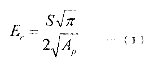
樹脂層の形成方法としては、例えば、ガラス基材の第1面側に形成された接合層上に、またはガラス基材の第一面に直接、樹脂組成物を塗布する方法が挙げられる。塗布方法としては、所望の厚さで塗布可能な方法であれば特に制限はなく、例えばグラビアコート法、グラビアリバースコート法、グラビアオフセットコート法、スピンコート法、ロールコート法、リバースロールコート法、ブレードコート法、ディップコート法、スクリーン印刷法等の一般的な塗布方法が挙げられる。
本実施態様におけるガラス積層体は、その厚さが、50μm以上300μm以下である。ガラス積層体の厚さが薄すぎると、耐衝撃性に劣る。ガラス積層体の厚さが厚すぎると、ガラス質感に劣る場合がある。ガラス積層体の厚さの下限値は、好ましくは70μm以上、更に好ましくは100μm以上である。一方、上限値は、好ましくは270μm以下であり、更に好ましくは240μm以下である。具体的な範囲としては、好ましくは70μm以上270μm以下であり、更に好ましくは100μm以上240μm以下である。
本実施態様におけるガラス積層体は、優れたガラス質感を有するものとなる。特に、ガラス積層体の樹脂層側から所定の表面性状測定方法により測定された光強度ばらつき値を所定の値以下とすることができる。また、反射光の光強度分布から算出される像鮮明度を高くすることができる。光強度ばらつき値、像鮮明度および測定方法については、後述する「C.ガラス積層体(第3実施態様)」、「D.ガラス積層体(第4実施態様)」と同様であるため、ここでの説明は省略する。
本実施態様におけるガラス積層体は、耐屈曲性を有することが好ましい。具体的には、ガラス積層体の耐屈曲性は、下記に説明するU字屈曲試験を行い、評価することができる。
本実施態様におけるガラス積層体の全光線透過率およびヘイズに関しては、「D.ガラス積層体(第1実施態様) 5.ガラス積層体の特性」の説明と同様であるので、ここでの説明は、省略する。
本実施態様におけるガラス積層体は、表示装置において、表示パネルよりも観察者側に配置される部材、すなわち表示装置用部材に用いることができる。
本実施態様におけるガラス積層体は、表示装置の表面に配置する場合、ガラス基材側の面が表示パネル側、樹脂層側の面が外側になるように配置されていることが好ましい。
図19は、本実施態様におけるガラス積層体の一例を示す概略断面図である。図19(A)に示すガラス積層体10は、ガラス基材1と、ガラス基材1の第1面1A側に配置された、1層の樹脂層3と、を有し、樹脂層3がガラス基材1と接している。また、図19(A)に示すガラス積層体10は、ガラス基材1の第1面1A側に接合層を有さない。
本実施態様のガラス積層体は、第1面および上記第1面に対向する第2面を有するガラス基材と、上記ガラス基材の上記第1面側に配置された樹脂層と、を有するガラス積層体であって、上記ガラス基材は、化学強化ガラスであり、厚さが20μm以上200μm以下であり、上記ガラス基材において少なくとも上記第1面が、表面圧縮応力値の平均値(CSav)が400Mpa以上800MPa以下であり、上記ガラス積層体の厚みが50μm以上であり、上記ガラス積層体は、上記樹脂層側から、後述する表面性状測定方法により測定される光強度のばらつき値が、10.5%以下であることを特徴とする。
さらに、本実施態様におけるガラス積層体の厚さが所定の値以上であるため、耐衝撃性に優れるものとなる。
表面性状測定方法を用いることにより測定される光強度ばらつき値は、ガラス積層体表面の凹凸やうねり等の表面性状による光強度のばらつき度合いを示し、この値が低いほど、ガラス質感に優れるものとなる。本実施態様におけるガラス積層体の樹脂層側から測定される光強度のばらつき値は、9.0%以下であることが好ましい。
本実施態様におけるガラス基材の厚さおよび第1面の表面圧縮応力値の平均値(CSav)については「E.ガラス積層体(第2実施態様) 1.ガラス基材」と同様である。
本実施態様におけるガラス積層体は、第1面および上記第1面に対向する第2面を有するガラス基材と、上記ガラス基材の上記第1面側に配置された樹脂層と、を有するガラス積層体であって、上記ガラス基材は、化学強化ガラスであり、厚さが20μm以上200μm以下であり、上記ガラス基材において少なくとも上記第1面が、表面圧縮応力値の平均値(CSav)が400Mpa以上800MPa以下であり、上記ガラス積層体の厚みが50μm以上であり、上記樹脂層側から測定される反射像鮮明度が、65%以上である。
さらに、本実施態様におけるガラス積層体の厚さが所定の値以上であるため、耐衝撃性に優れるものとなる。
像鮮明度は、被測定面の反射像が、どの程度鮮明に歪みなく見えるかの度合いを示し、この値が高いほど、ガラス質感に優れるものとなる。像鮮明度の下限値は、65%以上であり、好ましくは70%以上である。一方、上限値は、100%以下である。具体的な範囲としては、65%以上100%以下であり、好ましくは70%以上100%以下である。
本実施態様におけるガラス基材の厚さおよび第1面の表面圧縮応力値の平均値(CSav)については「E.ガラス積層体(第2実施態様) 1.ガラス基材」と同様である。
図20は、本開示における表示装置用部材の一例を示す概略断面図である。
本開示における表示装置用部材60は、ガラス積層体10と、ガラス積層体10の樹脂層3側に配置された機能層4とを有する。機能層としては、例えば、保護層、反射防止層、防眩層等が挙げられる。
本開示における表示装置は、表示パネルと、上記表示パネルの観察者側に配置された、上述のガラス基材、上述のガラス積層体、または上述の表示装置用部材と、を備える。
上述のように、化学強化ガラスであるガラス基材の厚さを薄くすると、鮮明度等のガラス特有の視覚的質感が悪化する場合があり、ガラス質感を定量的に評価する方法が求められている。
本実施態様におけるガラス基材の検査方法は、第1面と、上記第1面に対向する第2面と、を有し、化学強化ガラスであるガラス基材の検査方法であって、上記第1面側から測定される反射像鮮明度が、70%以上であるガラス基材を選別する工程を有する。
上述のように、化学強化ガラスであるガラス基材の厚さを薄くすると、鮮明度等のガラス特有の視覚的質感が悪化する場合があり、ガラス積層体のガラス質感を定量的に評価する方法が求められている。
本実施態様におけるガラス積層体の検査方法は、第1面および上記第1面に対向する第2面を有し、化学強化ガラスであるガラス基材と、上記ガラス基材の上記第1面側に配置された樹脂層と、を有するガラス積層体の検査方法であって、上記樹脂層側から測定される反射像鮮明度が、65%以上であるガラス積層体を選別する工程を有する。
本実施態様では、上述のガラス基材の検査方法を行うガラス基材検査工程を有する、表示装置の製造方法を提供する。即ち、本実施態様における表示装置の製造方法では、上述のガラス基材の検査方法により選別されたガラス基材を用いて、表示装置を製造する。選別されたガラス基材は、必要に応じて樹脂層が形成され、表示装置用部材として用いられる。表示装置用部材は、表示装置において、表示パネルよりも観察者側に配置される部材として用いることができる
本実施態様では、上述のガラス積層体の検査方法を行うガラス積層体検査工程を有する、表示装置の製造方法を提供する。即ち、本実施態様における表示装置の製造方法では、上述のガラス積層体の検査方法により選別されたガラス積層体を用いて、表示装置を製造する。選別されたガラス積層体は、表示装置用部材として用いられる。表示装置用部材は、表示装置において、表示パネルよりも観察者側に配置される部材として用いることができる。
[ガラス基材の作製]
(実施例I-1~I-10、比較例I-1~I-6)
表1に示す厚さ(平均値(Tav)、標準偏差(Tσ)および変動係数(Tσ/Tav))を有するガラス基材に対し、化学強化処理を行い、表1に示す表面圧縮応力(平均値(CSav)、標準偏差(CSσ)および変動係数(CSσ/CSav))を有する化学強化ガラスを得た。なお、厚みの平均値(Tav)、標準偏差(Tσ)および変動係数(Tσ/Tav)、および表面圧縮応力値の平均値(CSav)、標準偏差(CSσ)および変動係数(CSσ/CSav)の測定は、以下のように行った。
ガラス基材の厚さの平均値(Tav)は、ガラス基材を第1面および第2面と平行な平面において第1方向(x方向)および第1方向に垂直な第2方向(y方向)にそれぞれ3分割し、9エリアを作製し、各エリア中の1点で厚さを測定し、測定ポイント9点の算術平均を求めることによって得た。さらに、これらの測定値の標準偏差(Tσ)および変動係数(Tσ/Tav)を求めた。
実施例I-1~I-10、および比較例I-1~I-6のガラス基材について、ガラス基材の第1面をその平面における第1方向(x方向)および第1方向に垂直な第2方向(y方向)にそれぞれ3分割し、9エリアを作製し、各エリア中の1点で表面圧縮応力値CSを測定し、測定ポイント9点の算術平均を求めることによって表面圧縮応力値の平均値(CSav)を得た。
表面圧縮応力値CSの測定は、ルケオ社製の屈折計型ガラス表面応力計 FSM-6000LEを用いた。さらに、これらの測定値の標準偏差(CSσ)および変動係数(CSσ/CSav)を測定した。なお、FSM-6000LEの測定条件(装置設計)は、以下の通りとした。
光源:365nm
屈折率(プリズム):1.756
光路長:192.7mm
実施例I-1~I-10、および比較例I-1~I-6のガラス基材について、ルケオ社製の屈折計型ガラス表面応力計 FSM-6000LEを用いて上記測定条件にて、第1面から、圧縮応力層の深さ(DOL)の平均値および内部引張応力(CT)の平均値を測定した。
これらの平均値は、上述の9点の測定ポイントでのDOLおよびCTの平均値である。
実施例I-1~I-10、および比較例I-1~I-6のガラス基材について、上述した「C.ガラス基材(第3実施態様)」中に記載の方法により、像鮮明度を測定した。結果を表1に示す。
実施例I-1~I-10、および比較例I-1~I-6のガラス基材について、上述した「B.ガラス基材(第2実施態様)」中に記載の方法により、光強度ばらつき値を測定した。結果を表1に示す。
LED光源を用い、実施例I-1~I-10、および比較例I-1~I-6のガラス基材の第1面側から光を照射し反射させ、第1面側から目視観察し、以下の評価基準で評価した。結果を表1に示す。観察は、室内(暗室ではない)で行った。
・評価基準
20人で目視観察を行い、ゆがみ、不均一性がないがないと判断した人数により評価する。
A:18人以上
B:10人以上
C:5人以上
D:4人以下
ガラス基材に対して、上述のU字屈曲試験を行った。そして、ガラス基材に割れまたは破断が生じなかったときの、ガラス基材の対向する2つの短辺部の間隔d(mm)の最小値を測定した。結果を表1に示す。
上記で得られたガラス基材を、100mm×100mmの大きさに切断し、この試験片を水平な基台上に5分間載置した。基台と試験片との間に生じる隙間(ガラス基材の浮き)の最大距離を隙間ゲージ(SUS板)で測定した。また、320mm×280mmの大きさに切断した試験片を用いた場合のガラス基材の浮きも同様に測定した。結果を表1に示す。
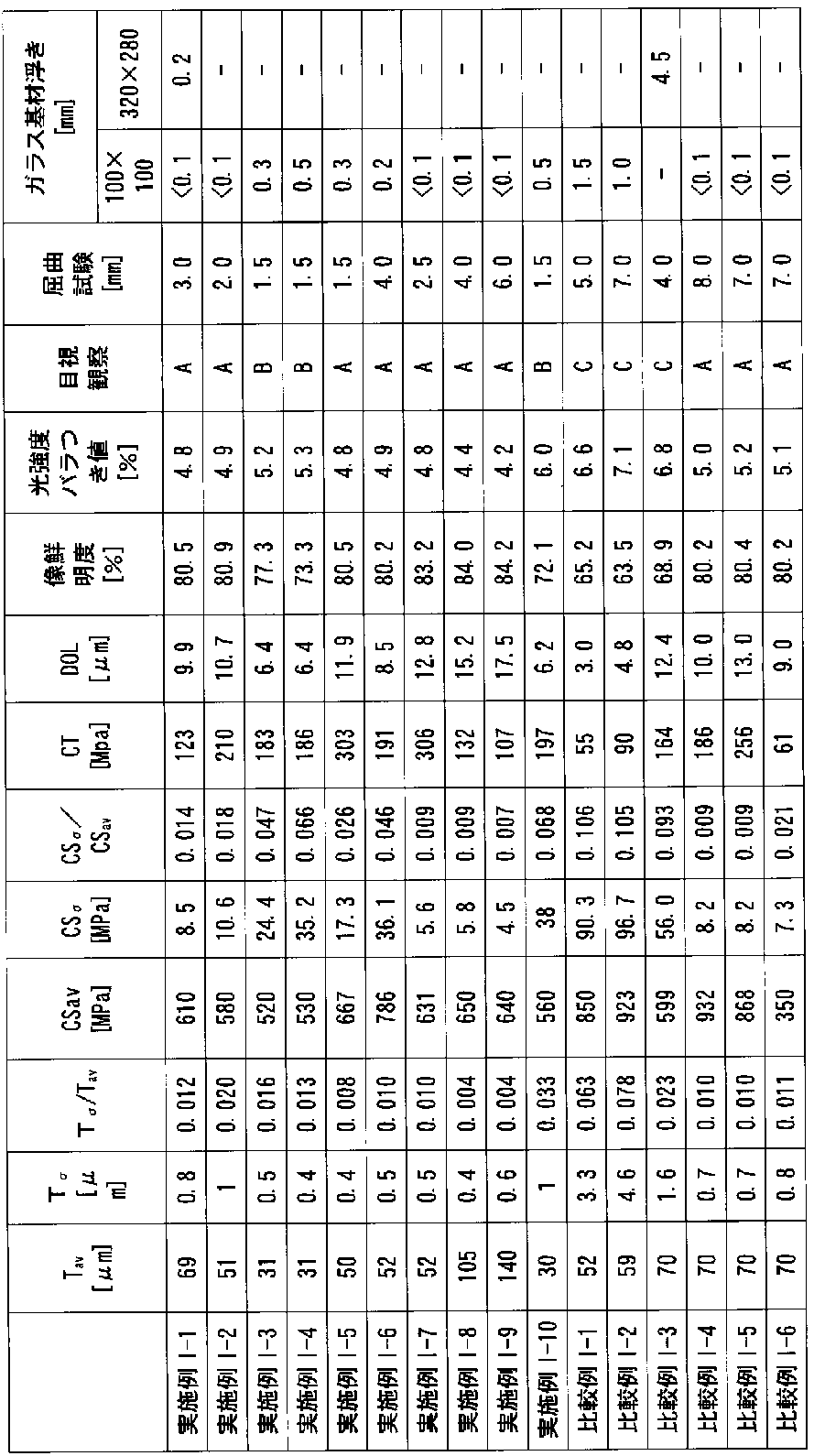
[ガラス基材の作製]
表2に示す厚さ(T1)を有するガラス基材に対し、化学強化処理を行い、第1面が、表2に示す表面圧縮応力(平均値(CSav)、標準偏差(CSσ)および変動係数(CSσ/CSav))を有する化学強化ガラスを得た。なお、ガラス基材の厚さ(T1)は、ガラス基材を第1面および第2面と平行な平面において第1方向(x方向)および第1方向に垂直な第2方向(y方向)にそれぞれ3分割し、9エリアを作製し、各エリア中の1点で厚さを測定し、測定ポイント9点の算術平均を求めることによって得た。
[表面圧縮応力値の平均値(CSav)、標準偏差(CSσ)および変動係数(CSσ/CSav)]
ガラス基材について、ガラス基材の第1面をその平面における第1方向(x方向)および第1方向に垂直な第2方向(y方向)にそれぞれ3分割し、9エリアを作製し、各エリア中の1点で表面圧縮応力値CSを測定し、測定ポイント9点の算術平均を求めることによって表面圧縮応力値の平均値(CSav)を得た。表面圧縮応力値CSの測定は、ルケオ社製の屈折計型ガラス表面応力計 FSM-6000LEを用いた。さらに、これらの測定値の標準偏差(CSσ)および変動係数(CSσ/CSav)を測定した。
(実施例II-1)
まず、厚さ50μmの樹脂基材(東洋紡社製「A4160(現品番)」(「A4100(旧品番)」)、複合弾性率6.9GPa)に、下記ハードコート組成物を塗工し、厚さ10μmのハードコート層を形成した。これにより、厚さ60μmのハードコートフィルム(樹脂層)を準備した。
下記に示す組成となるように各成分を配合して、ハードコート組成物を調製した。
・ジペンタエリスリトールペンタアクリレートとジペンタエリスリトールヘキサアクリレートの混合物(M403、東亜合成社製) 25質量部
・ジペンタエリスリトールEO変性ヘキサアクリレート(A-DPH-6E、新中村化学社製) 25質量部
・異型シリカ微粒子(平均粒径25nm、日揮触媒化成社製) 50質量部(固形換算)・光重合開始剤(Irg184) 4質量部
・フッ素系レベリング剤(F568、DIC社製) 0.2質量部(固形換算)
・紫外線吸収剤1(DAINSORB P6、大和化成製) 3質量部
・溶剤(MIBK) 150質量部
・非晶性ポリエステル系樹脂(バイロン240、東洋紡社製) 100質量部
・ヘキサンメチレンジイソシアネート(コロネート2203、日本ポリウレタン工業社製) 5質量部
・シランカップリング剤(KBM-403、信越化学工業社製) 5質量部
・フッ素系レベリング剤(F568、DIC社製) 0.2質量部(固形換算)
・溶剤(MEK) 310質量部
・溶剤(トルエン) 310質量部
ガラス基材を表2に記載の厚さ(T1)、表面圧縮応力値の平均値(CSav)、標準偏差(CSσ)および変動係数(CSσ/CSav)を有するものに変更した以外は、実施例II-1と同様の方法でガラス積層体を製造した。
ガラス基材を表2に記載の厚さ(T1)、表面圧縮応力値の平均値(CSav)、標準偏差(CSσ)および変動係数(CSσ/CSav)を有するものに変更した。また、感熱接着層用材料を以下の配合組成に変更し、表2中の乾燥後の膜厚となるように接合層(複合弾性率 2.4Gpa)を形成し、樹脂層を、厚さ70μmのハードコートフィルム(厚さ50μmの樹脂基材(東洋紡社製「A4160(現品番)」(「A4100(旧品番)」)、複合弾性率6.9GPa)に、厚さ20μmのハードコート層を形成したもの)とした以外は、実施例II-1と同様の方法でガラス積層体を製造した。
ポリエステルウレタン系樹脂(UR-8300、固形分30%、東洋紡社製) 100質量部
・ヘキサンメチレンジイソシアネート(コロネート2203、日本ポリウレタン工業社製) 1.5質量部
・シランカップリング剤(KBM-403、信越化学工業社製) 1.5質量部
・フッ素系レベリング剤(F568、DIC社製) 0.2質量部(固形換算)
・溶剤(MEK) 58質量部
・溶剤(トルエン) 58質量部
実施例II-3で製造したガラス積層体サンプルに、接合層(OCA、リンテック製NCF-D692 厚さ15μm、複合弾性率0.02Gpa)を介して、実施例II-1で使用した厚さ60μmのハードコートフィルム(第2樹脂層)を貼合した。なお、ハードコートフィルムのハードコート側の面が外側となるように、貼合した。
表2に示す厚さ(T1)、表面圧縮応力値の平均値(CSav)、標準偏差(CSσ)および変動係数(CSσ/CSav)を有するガラス基材を作製した。上記ガラス基材上に、下記のプライマー層用組成物をコーティングし、80℃で3分間および150℃で60分間乾燥させ、厚さ1μmのプライマー層を形成した。
・ビスフェノールA型固形エポキシ樹脂(jER1256B40 三菱ケミカル製) 28質量部
・ビスフェノールAノボラック型固形エポキシ樹脂(jER157S65B80 三菱ケミカル製) 5質量部
・2-エチル-4-メチルイミダゾール(東京化成工業製) 1質量部
・溶剤(MEK) 11質量部
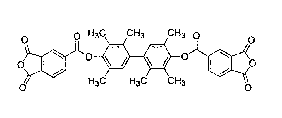
表2に示す厚さ(T1)、表面圧縮応力値の平均値(CSav)、標準偏差(CSσ)および変動係数(CSσ/CSav)を有するガラス基材を作製した。作製したガラス基材を用い、接合層の厚さを表2に示す値(25μm)とした以外は、実施例II-1と同様の方法でガラス積層体を製造した。
接合層の材料として、ポリエステル系でTgが-20℃となる材料を用い、厚みを10μmとした以外は、実施例II-3と同様にしてガラス積層体を製造した。
接合層の材料として、実施例II-8の材料を用い、厚みを6μmとした以外は、実施例II-2と同様にしてガラス積層体を製造した。
表2に示す厚さ(T1)、表面圧縮応力値の平均値(CSav)、標準偏差(CSσ)および変動係数(CSσ/CSav)を有するガラス基材を作製した。実施例II-1で使用した厚さ60μmのハードコートフィルムとガラス基材とを、厚さ50μmの接合層(光学透明粘着フィルム(OCA)(3M社製「8146-2」、複合弾性率9.6MPa))を介してハンドロールで貼合した。なお、ハードコートフィルムの基材層側の面がガラス基材側となるように、貼合した。
表2に示す厚さ(T1)、表面圧縮応力値の平均値(CSav)、標準偏差(CSσ)および変動係数(CSσ/CSav)を有するガラス基材を作製した以外は、実施例II-1と同様の方法で、ガラス積層体を製造した。
表2に示す厚さ(T1)、表面圧縮応力値の平均値(CSav)、標準偏差(CSσ)および変動係数(CSσ/CSav)を有するガラス基材を作製した。実施例II-1で使用した厚さ60μmのハードコートフィルムとガラス基材とを、厚さ50μmの接合層(光学透明粘着フィルム(OCA)(3M社製「8146-2」、複合弾性率9.6MPa))を介してハンドロールで貼合し、ガラス積層体を得た。なお、ハードコートフィルムの基材層側の面がガラス基材側となるように、貼合した。
表2に示す厚さ(T1)、表面圧縮応力値の平均値(CSav)、標準偏差(CSσ)および変動係数(CSσ/CSav)を有するガラス基材を作製した。また、実施例II-6と同様の方法で、ガラス基材の第1面側に、厚さ10μmの樹脂層を形成した。
比較例II-4で得られたガラス積層体に対して、実施例II-5と同様に、ハードコートフィルム(第2樹脂層)を貼合し、ガラス積層体を得た。
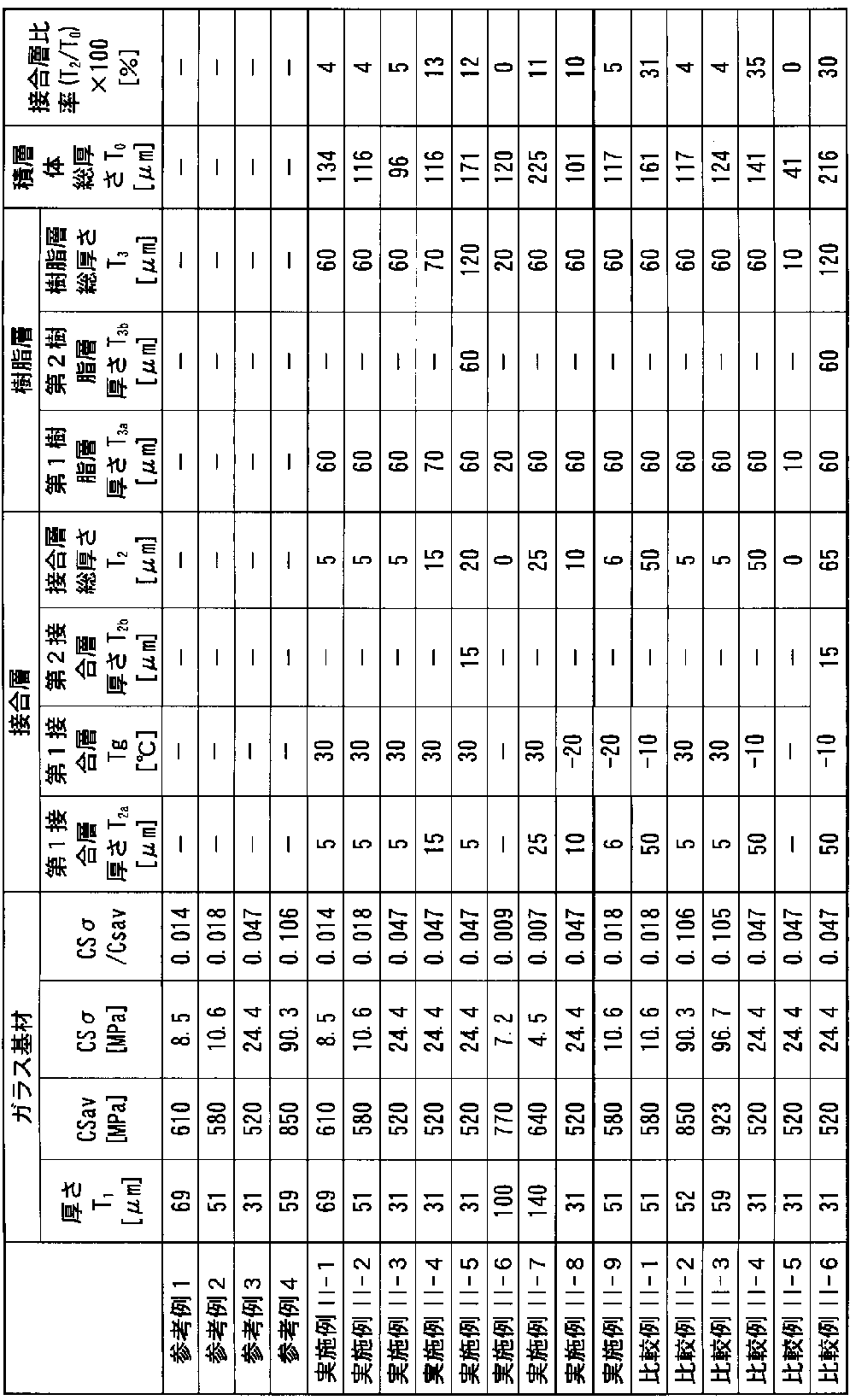
実施例II-1~II-7および比較例II-1~II-6のガラス積層体について、樹脂層側の面を被測定面21として、上述した図11に示す評価用サンプルを作製し、上述した「D.ガラス積層体(第4実施態様)」中に記載の方法により、像鮮明度を測定した。また、参考例1~4のガラス基材も同様の方法で像鮮明度を測定した。結果を表3に示す。
実施例II-1~II-7および比較例II-1~II-6のガラス積層体について、上述した「C.ガラス積層体(第3実施態様)」中に記載の方法により、光強度ばらつき値を測定した。また、参考例1~4のガラス基材も同様の方法で光強度ばらつき値を測定した。結果を表3に示す。
LED光源を用い、実施例II-1~II-7および比較例II-1~II-6のガラス積層体を樹脂層側から光を照射し反射させ、樹脂層側から目視観察し、以下の評価基準で評価した。結果を表3に示す。観察は、室内(暗室ではない)で行った。また、参考例1~4のガラス基材も同様の方法で目視観察を行った。結果を表3に示す。
20人で目視観察を行い、ゆがみ、不均一性がないがないと判断した人数により評価する。
A:18人以上
B:10人以上
C:5人以上
D:4人以下
実施例II-1~II-7および比較例II-1~II-6のガラス積層体、ならびに参考例1~4のガラス基材に対して、上述のU字屈曲試験を行った。ガラス積層体の試験においては、樹脂層側が内側、ガラス基材側が外側となるようにガラス積層体を折りたたんだ。そして、ガラス積層体またはガラス基材に割れまたは破断が生じなかったときの、ガラス積層体の対向する2つの短辺部の間隔d(mm)の最小値を測定した。結果を表3に示す。
実施例II-1~II-7および比較例II-1~II-6のガラス積層体に対して衝撃試験を行った。まず、ガラス積層体のガラス基材側の面に、厚さ50μmの光学粘着フィルム(OCA)と、厚さ100μmのPETフィルムとをこの順に貼り合わせて、試験用積層体を作製した。この試験用積層体のPETフィルム側の面が厚さ30mmの金属プレートに接するように、金属プレート上に試験用積層体を置いた。次に、試験高さより、ペンをその先端を下にして試験用積層体上に落下させた。ペンには、ゼブラ社製のブレン0.5BAS88-BK(重量12g、ペン先0.5mmφ)を用いた。そしてガラス積層体に割れが生じなかった最大の試験高さ(cm)を測定した。結果を表3に示す。なお、数値が大きいほど、耐衝撃性が高いことを示す。

一方、第1面の表面圧縮応力値の平均値(CSav)が800MPaより大きいガラス基材を用いた場合においては、耐屈曲性に劣り、表面圧縮応力値の平均値(CSav)に対する表面圧縮応力値の標準偏差(CSσ)の割合(CSσ/CSav)が0.090より大きいガラス基材を用いた場合においては、良好なガラス質感を得ることができないことが確認された(比較例II-2、II-3)。また、参考例2、3の良好なガラス質感を有するガラス基材を用いた場合でも、接合層の総厚さが、ガラス積層体の厚さに対して25%より大きい場合には、良好なガラス質感を得ることができないことが確認された(比較例II-1、II-4、II-6)。また、ガラス積層体の厚さが50μm未満である場合には、耐衝撃性に劣ることが確認された(比較例II-5)。
さらに、実施例II-8と実施例II-5、および実施例II-9と実施例II-2の対比から、接合層のガラス転移点(Tg)の温度が高いものほど像鮮明度の値が良好となることが分かった。
[1]
第1面と、上記第1面に対向する第2面と、を有するガラス基材であって、
化学強化ガラスであり、
上記ガラス基材における厚さの平均値(Tav)が20μm以上200μm以下であり、
上記ガラス基材において少なくとも上記第1面が、表面圧縮応力値の平均値(CSav)が400Mpa以上800MPa以下であり、かつ、上記表面圧縮応力値の平均値(CSav)に対する上記表面圧縮応力値の標準偏差(CSσ)の割合(CSσ/CSav)が0.090以下である、ガラス基材。
[2]
上記厚さの平均値(Tav)に対する厚さの標準偏差(Tσ)の割合(Tσ/Tav)が、0.003以上0.050以下である、[1]に記載のガラス基材。
[3]
上記第1面の圧縮応力層の深さ(DOL)が、5μm以上20μm以下である、[1]または[2]に記載のガラス基材。
[4]
内部引張応力(CT)が、80MPa以上350MPa以下である、[1]から[3]までのいずれかに記載のガラス基材。
[5]
上記ガラス基材を水平な基台上に載置した場合に、上記基台との間に生じる隙間の最大距離が、
100mm×100mmの大きさの上記ガラス基材の試験片とした場合に、0.6mm以下である、または、
280mm×320mmの大きさの上記ガラス基材の試験片とした場合に、20mm以下である、[1]から[4]までのいずれかに記載のガラス基材。
[6]
上記第1面側から下記表面性状測定方法により測定される光強度のばらつき値が、6.5%以下である、[1]から[5]までのいずれかに記載のガラス基材。
[表面性状測定方法]
(1)上記ガラス基材の上記第1面である被測定面に、4つの線状の明領域および暗領域を有する照明光を照射する。
(2)撮像装置を用いて上記被測定面に焦点を合わせて、上記被測定面で反射し、上記照明光の上記明領域および上記暗領域に対応する線状の明領域および暗領域を有する反射光を受光し、上記被測定面における上記反射光の光強度分布を検出する。
(3)上記被測定面における上記反射光の光強度分布を、上記反射光の上記線状明領域の長手方向に1100個の分割領域に分割し、上記分割領域毎かつ上記明領域毎に、光強度のピーク値を示す位置から所定の値離れた位置の光強度を求める。
(4)上記各明領域の上記光強度の変動係数を求め、4つの明領域の変動係数の算術平均値を計算する。
[7]
上記第1面側から測定される反射像鮮明度が、70%以上である、[1]から[6]までのいずれかに記載のガラス基材。
[8]
第1面と、上記第1面に対向する第2面と、を有するガラス基材であって、
化学強化ガラスであり、
上記ガラス基材における厚さの平均値(Tav)が20μm以上200μm以下であり、
上記ガラス基材において少なくとも上記第1面は、表面圧縮応力値の平均値(CSav)が400Mpa以上800MPa以下であり、
上記第1面側から下記表面性状測定方法により測定される光強度のばらつき値が6.5%以下である、ガラス基材。
[表面性状測定方法]
(1)上記ガラス基材の上記第1面である被測定面に、4つの線状の明領域および暗領域を有する照明光を照射する。
(2)撮像装置を用いて上記被測定面に焦点を合わせて、上記被測定面で反射し、上記照明光の上記明領域および上記暗領域に対応する線状の明領域および暗領域を有する反射光を受光し、上記被測定面における上記反射光の光強度分布を検出する。
(3)上記被測定面における上記反射光の光強度分布を、上記反射光の上記線状明領域の長手方向に1100個の分割領域に分割し、上記分割領域毎かつ上記明領域毎に、光強度のピーク値を示す位置から所定の値離れた位置の光強度を求める。
(4)上記各明領域の上記光強度の変動係数を求め、4つの明領域の変動係数の算術平均値を計算する。
[9]
上記第1面側から測定される反射像鮮明度が70%以上である、[8]に記載のガラス基材。
[10]
第1面と、上記第1面に対向する第2面と、を有するガラス基材であって、
化学強化ガラスであり、
上記ガラス基材における厚さの平均値(Tav)が20μm以上200μm以下であり、
上記ガラス基材において少なくとも上記第1面は、表面圧縮応力値の平均値(CSav)が400Mpa以上800MPa以下であり、上記第1面側から測定される反射像鮮明度が、70%以上である、ガラス基材。
[11]
[1]から[10]までのいずれかに記載のガラス基材と、
上記ガラス基材の第1面側および第2面側の少なくとも一方に配置された樹脂層と、
を有する、ガラス積層体。
[12]
[1]から[7]までのいずれかに記載のガラス基材と、
上記ガラス基材の上記第1面側に配置された樹脂層と、を有する、ガラス積層体であって、
上記ガラス積層体は、厚さが50μm以上300μm以下であり、
上記ガラス積層体は、上記ガラス基材の上記第1面側に配置された接合層を含み、上記ガラス積層体の厚さに対して、上記接合層の総厚さが25%以下である、ガラス積層体。
[13]
[1]から[7]までのいずれかに記載のガラス基材と、
上記ガラス基材の上記第1面側に配置された樹脂層と、を有する、ガラス積層体であって、
上記ガラス積層体は、厚さが50μm以上300μm以下であり、
上記ガラス積層体は、上記樹脂層が上記ガラス基材と接している、ガラス積層体。
[14]
上記樹脂層の総厚みが、10μm以上100μm以下である、[12]または[13]に記載のガラス積層体。
[15]
上記ガラス積層体は、上記樹脂層側から、下記表面性状測定方法により測定される光強度のばらつき値が、10.5%以下である、[12]から[14]までのいずれかに記載のガラス積層体。
[表面性状測定方法]
(1)上記ガラス積層体の上記樹脂層の表面である被測定面に、4つの線状の明領域および暗領域を有する照明光を照射する。
(2)撮像装置を用いて上記被測定面に焦点を合わせて、上記被測定面で反射し、上記照明光の上記明領域および上記暗領域に対応する線状の明領域および暗領域を有する反射光を受光し、上記被測定面における上記反射光の光強度分布を検出する。
(3)上記被測定面における上記反射光の光強度分布を、上記反射光の上記線状明領域の長手方向に1100個の分割領域に分割し、上記分割領域毎かつ上記明領域毎に、光強度のピーク値を示す位置から所定の値離れた位置の光強度を求める。
(4)上記各明領域の上記光強度の変動係数を求め、4つの明領域の変動係数の算術平均値を計算する。
[16]
上記ガラス積層体は、上記樹脂層側から測定される反射像鮮明度が、65%以上である、[12]から[15]までのいずれかに記載のガラス積層体。
[17]
第1面および上記第1面に対向する第2面を有するガラス基材と、
上記ガラス基材の上記第1面側に配置された樹脂層と、を有するガラス積層体であって、
上記ガラス基材は、化学強化ガラスであり、厚さが20μm以上200μm以下であり、
上記ガラス基材において少なくとも上記第1面が、表面圧縮応力値の平均値(CSav)が400Mpa以上800MPa以下であり、
上記ガラス積層体の厚みが50μm以上であり、
上記ガラス積層体は、上記樹脂層側から、下記表面性状測定方法により測定される光強度のばらつき値が、10.5%以下である、ガラス積層体。
[表面性状測定方法]
(1)上記ガラス積層体の上記樹脂層の表面である被測定面に、4つの線状の明領域および暗領域を有する照明光を照射する。
(2)撮像装置を用いて上記被測定面に焦点を合わせて、上記被測定面で反射し、上記照明光の上記明領域および上記暗領域に対応する線状の明領域および暗領域を有する反射光を受光し、上記被測定面における上記反射光の光強度分布を検出する。
(3)上記被測定面における上記反射光の光強度分布を、上記反射光の上記線状明領域の長手方向に1100個の分割領域に分割し、上記分割領域毎かつ上記明領域毎に、光強度のピーク値を示す位置から所定の値離れた位置の光強度を求める。
(4)上記各明領域の上記光強度の変動係数を求め、4つの明領域の変動係数の算術平均値を計算する。
[18]
上記樹脂層側から測定される反射像鮮明度が、65%以上である、[17]に記載のガラス積層体。
[19]
第1面および上記第1面に対向する第2面を有するガラス基材と、
上記ガラス基材の上記第1面側に配置された樹脂層と、を有するガラス積層体であって、
上記ガラス基材は、化学強化ガラスであり、厚さが20μm以上200μm以下であり、
上記ガラス基材において少なくとも上記第1面が、表面圧縮応力値の平均値(CSav)が400Mpa以上800MPa以下であり、
上記ガラス積層体の厚みが50μm以上であり、上記樹脂層側から測定される反射像鮮明度が、65%以上である、ガラス積層体。
[20]
[11]から[19]までのいずれかに記載のガラス積層体と、上記ガラス積層体の上記樹脂層側に配置された機能層と、を有する表示装置用部材。
[21]
表示パネルと、
上記表示パネルの観察者側に配置された、[1]から[10]までのいずれに記載のガラス基材と、
を備える表示装置。
[22]
表示パネルと、
上記表示パネルの観察者側に配置された、[11]から[19]までのいずれかに記載のガラス積層体、または[20]に記載の表示装置用部材と、を備え、
上記ガラス積層体あるいは上記表示装置用部材は、上記ガラス積層体の上記樹脂層側が観察者側となるように配置される、表示装置。
[23]
第1面と、上記第1面に対向する第2面と、を有し、化学強化ガラスであるガラス基材の検査方法であって、
上記第1面側から下記表面性状測定方法により測定される光強度ばらつき値が、6.5%以下である、ガラス基材を選別する工程を有する、ガラス基材の検査方法。
[表面性状測定方法]
(1)上記ガラス基材の上記第1面である被測定面に、4つの線状の明領域および暗領域を有する照明光を照射する。
(2)撮像装置を用いて上記被測定面に焦点を合わせて、上記被測定面で反射し、上記照明光の上記明領域および上記暗領域に対応する線状の明領域および暗領域を有する反射光を受光し、上記被測定面における上記反射光の光強度分布を検出する。
(3)上記被測定面における上記反射光の光強度分布を、上記反射光の上記線状明領域の長手方向に1100個の分割領域に分割し、上記分割領域毎かつ上記明領域毎に、光強度のピーク値を示す位置から所定の値離れた位置の光強度を求める。
(4)上記各明領域の上記光強度の変動係数を求め、4つの明領域の変動係数の算術平均値を計算する。
[24]
さらに、上記第1面側から測定される反射像鮮明度が、70%以上であるガラス基材を選別する工程を有する、[23]に記載のガラス基材の検査方法。
[25]
第1面と、上記第1面に対向する第2面と、を有し、化学強化ガラスであるガラス基材の検査方法であって、上記第1面側から測定される反射像鮮明度が、70%以上であるガラス基材を選別する工程を有する、ガラス基材の検査方法。
[26]
第1面および上記第1面に対向する第2面を有し、化学強化ガラスであるガラス基材と、上記ガラス基材の上記第1面側に配置された樹脂層と、を有するガラス積層体の検査方法であって、
上記樹脂層側から、下記表面性状測定方法により測定される光強度ばらつき値が、10.5%以下である、ガラス積層体を選別する工程を有する、ガラス積層体の検査方法。
[表面性状測定方法]
(1)上記ガラス積層体の上記樹脂層の表面である被測定面に、4つの線状の明領域および暗領域を有する照明光を照射する。
(2)撮像装置を用いて上記被測定面に焦点を合わせて、上記被測定面で反射し、上記照明光の上記明領域および上記暗領域に対応する線状の明領域および暗領域を有する反射光を受光し、上記被測定面における上記反射光の光強度分布を検出する。
(3)上記被測定面における上記反射光の光強度分布を、上記反射光の上記線状明領域の長手方向に1100個の分割領域に分割し、上記分割領域毎かつ上記明領域毎に、光強度のピーク値を示す位置から所定の値離れた位置の光強度を求める。
(4)上記各明領域の上記光強度の変動係数を求め、4つの明領域の変動係数の算術平均値を計算する。
[27]
さらに、上記樹脂層側から測定される反射像鮮明度が、65%以上であるガラス積層体を選別する工程を有する、[26]に記載のガラス積層体の検査方法。
[28]
第1面および上記第1面に対向する第2面を有し、化学強化ガラスであるガラス基材と、上記ガラス基材の上記第1面側に配置された樹脂層と、を有するガラス積層体の検査方法であって、上記樹脂層側から測定される反射像鮮明度が、65%以上であるガラス積層体を選別する工程を有する、ガラス積層体の検査方法。
[29]
[23]から[25]までのいずれかに記載のガラス基材の検査方法を行うガラス基材検査工程を有する、表示装置の製造方法。
[30]
[26]から[28]までのいずれかに記載のガラス積層体の検査方法を行うガラス積層体検査工程を有する、表示装置の製造方法。
1A … ガラス基材の第1面
1B … ガラス基材の第2面
10 … ガラス積層体
11、12 … 樹脂層
20 … 表示装置
21 … 表示パネル
Claims (30)
- 第1面と、前記第1面に対向する第2面と、を有するガラス基材であって、
化学強化ガラスであり、
前記ガラス基材における厚さの平均値(Tav)が20μm以上200μm以下であり、
前記ガラス基材において少なくとも前記第1面が、表面圧縮応力値の平均値(CSav)が400Mpa以上800MPa以下であり、かつ、前記表面圧縮応力値の平均値(CSav)に対する前記表面圧縮応力値の標準偏差(CSσ)の割合(CSσ/CSav)が0.090以下である、ガラス基材。 - 前記厚さの平均値(Tav)に対する厚さの標準偏差(Tσ)の割合(Tσ/Tav)が、0.003以上0.050以下である、請求項1に記載のガラス基材。
- 前記第1面の圧縮応力層の深さ(DOL)が、5μm以上20μm以下である、請求項1に記載のガラス基材。
- 内部引張応力(CT)が、80MPa以上350MPa以下である、請求項1に記載のガラス基材。
- 前記ガラス基材を水平な基台上に載置した場合に、前記基台との間に生じる隙間の最大距離が、
100mm×100mmの大きさの前記ガラス基材の試験片とした場合に、0.6mm以下である、または、
280mm×320mmの大きさの前記ガラス基材の試験片とした場合に、20mm以下である、請求項1に記載のガラス基材。 - 前記第1面側から下記表面性状測定方法により測定される光強度のばらつき値が、6.5%以下である、請求項1に記載のガラス基材。
[表面性状測定方法]
(1)前記ガラス基材の前記第1面である被測定面に、4つの線状の明領域および暗領域を有する照明光を照射する。
(2)撮像装置を用いて前記被測定面に焦点を合わせて、前記被測定面で反射し、前記照明光の前記明領域および前記暗領域に対応する線状の明領域および暗領域を有する反射光を受光し、前記被測定面における前記反射光の光強度分布を検出する。
(3)前記被測定面における前記反射光の光強度分布を、前記反射光の前記線状明領域の長手方向に1100個の分割領域に分割し、前記分割領域毎かつ前記明領域毎に、光強度のピーク値を示す位置から所定の値離れた位置の光強度を求める。
(4)前記各明領域の前記光強度の変動係数を求め、4つの明領域の変動係数の算術平均値を計算する。 - 前記第1面側から測定される反射像鮮明度が、70%以上である、請求項1に記載のガラス基材。
- 第1面と、前記第1面に対向する第2面と、を有するガラス基材であって、
化学強化ガラスであり、
前記ガラス基材における厚さの平均値(Tav)が20μm以上200μm以下であり、
前記ガラス基材において少なくとも前記第1面は、表面圧縮応力値の平均値(CSav)が400Mpa以上800MPa以下であり、
前記第1面側から下記表面性状測定方法により測定される光強度のばらつき値が6.5%以下である、ガラス基材。
[表面性状測定方法]
(1)前記ガラス基材の前記第1面である被測定面に、4つの線状の明領域および暗領域を有する照明光を照射する。
(2)撮像装置を用いて前記被測定面に焦点を合わせて、前記被測定面で反射し、前記照明光の前記明領域および前記暗領域に対応する線状の明領域および暗領域を有する反射光を受光し、前記被測定面における前記反射光の光強度分布を検出する。
(3)前記被測定面における前記反射光の光強度分布を、前記反射光の前記線状明領域の長手方向に1100個の分割領域に分割し、前記分割領域毎かつ前記明領域毎に、光強度のピーク値を示す位置から所定の値離れた位置の光強度を求める。
(4)前記各明領域の前記光強度の変動係数を求め、4つの明領域の変動係数の算術平均値を計算する。 - 前記第1面側から測定される反射像鮮明度が70%以上である、請求項8に記載のガラス基材。
- 第1面と、前記第1面に対向する第2面と、を有するガラス基材であって、
化学強化ガラスであり、
前記ガラス基材における厚さの平均値(Tav)が20μm以上200μm以下であり、
前記ガラス基材において少なくとも前記第1面は、表面圧縮応力値の平均値(CSav)が400Mpa以上800MPa以下であり、前記第1面側から測定される反射像鮮明度が、70%以上である、ガラス基材。 - 請求項1から請求項10までのいずれかの請求項に記載のガラス基材と、
前記ガラス基材の第1面側および第2面側の少なくとも一方に配置された樹脂層と、
を有する、ガラス積層体。 - 請求項1から請求項7までのいずれかの請求項に記載のガラス基材と、
前記ガラス基材の前記第1面側に配置された樹脂層と、を有する、ガラス積層体であって、
前記ガラス積層体は、厚さが50μm以上300μm以下であり、
前記ガラス積層体は、前記ガラス基材の前記第1面側に配置された接合層を含み、前記ガラス積層体の厚さに対して、前記接合層の総厚さが25%以下である、ガラス積層体。 - 請求項1から請求項7までのいずれかの請求項に記載のガラス基材と、
前記ガラス基材の前記第1面側に配置された樹脂層と、を有する、ガラス積層体であって、
前記ガラス積層体は、厚さが50μm以上300μm以下であり、
前記ガラス積層体は、前記樹脂層が前記ガラス基材と接している、ガラス積層体。 - 前記樹脂層の総厚みが、10μm以上100μm以下である、請求項12に記載のガラス積層体。
- 前記ガラス積層体は、前記樹脂層側から、下記表面性状測定方法により測定される光強度のばらつき値が、10.5%以下である、請求項12に記載のガラス積層体。
[表面性状測定方法]
(1)上記ガラス積層体の上記樹脂層の表面である被測定面に、4つの線状の明領域および暗領域を有する照明光を照射する。
(2)撮像装置を用いて上記被測定面に焦点を合わせて、上記被測定面で反射し、上記照明光の上記明領域および上記暗領域に対応する線状の明領域および暗領域を有する反射光を受光し、上記被測定面における上記反射光の光強度分布を検出する。
(3)上記被測定面における上記反射光の光強度分布を、上記反射光の上記線状明領域の長手方向に1100個の分割領域に分割し、上記分割領域毎かつ上記明領域毎に、光強度のピーク値を示す位置から所定の値離れた位置の光強度を求める。
(4)上記各明領域の上記光強度の変動係数を求め、4つの明領域の変動係数の算術平均値を計算する。 - 前記ガラス積層体は、前記樹脂層側から測定される反射像鮮明度が、65%以上である、請求項12に記載のガラス積層体。
- 第1面および前記第1面に対向する第2面を有するガラス基材と、
前記ガラス基材の前記第1面側に配置された樹脂層と、を有するガラス積層体であって、
前記ガラス基材は、化学強化ガラスであり、厚さが20μm以上200μm以下であり、
前記ガラス基材において少なくとも前記第1面が、表面圧縮応力値の平均値(CSav)が400Mpa以上800MPa以下であり、
前記ガラス積層体の厚みが50μm以上であり、
前記ガラス積層体は、前記樹脂層側から、下記表面性状測定方法により測定される光強度のばらつき値が、10.5%以下である、ガラス積層体。
[表面性状測定方法]
(1)上記ガラス積層体の上記樹脂層の表面である被測定面に、4つの線状の明領域および暗領域を有する照明光を照射する。
(2)撮像装置を用いて上記被測定面に焦点を合わせて、上記被測定面で反射し、上記照明光の上記明領域および上記暗領域に対応する線状の明領域および暗領域を有する反射光を受光し、上記被測定面における上記反射光の光強度分布を検出する。
(3)上記被測定面における上記反射光の光強度分布を、上記反射光の上記線状明領域の長手方向に1100個の分割領域に分割し、上記分割領域毎かつ上記明領域毎に、光強度のピーク値を示す位置から所定の値離れた位置の光強度を求める。
(4)上記各明領域の上記光強度の変動係数を求め、4つの明領域の変動係数の算術平均値を計算する。 - 前記樹脂層側から測定される反射像鮮明度が、65%以上である、請求項17に記載のガラス積層体。
- 第1面および前記第1面に対向する第2面を有するガラス基材と、
前記ガラス基材の前記第1面側に配置された樹脂層と、を有するガラス積層体であって、
前記ガラス基材は、化学強化ガラスであり、厚さが20μm以上200μm以下であり、
前記ガラス基材において少なくとも前記第1面が、表面圧縮応力値の平均値(CSav)が400Mpa以上800MPa以下であり、
前記ガラス積層体の厚みが50μm以上であり、前記樹脂層側から測定される反射像鮮明度が、65%以上である、ガラス積層体。 - 請求項12に記載のガラス積層体と、前記ガラス積層体の前記樹脂層側に配置された機能層と、を有する表示装置用部材。
- 表示パネルと、
前記表示パネルの観察者側に配置された、請求項1に記載のガラス基材と、
を備える表示装置。 - 表示パネルと、
前記表示パネルの観察者側に配置された、請求項12に記載のガラス積層体、または請求項20に記載の表示装置用部材と、を備え、
前記ガラス積層体あるいは前記表示装置用部材は、前記ガラス積層体の前記樹脂層側が観察者側となるように配置される、表示装置。 - 第1面と、前記第1面に対向する第2面と、を有し、化学強化ガラスであるガラス基材の検査方法であって、
前記第1面側から下記表面性状測定方法により測定される光強度ばらつき値が、6.5%以下である、ガラス基材を選別する工程を有する、ガラス基材の検査方法。
[表面性状測定方法]
(1)前記ガラス基材の前記第1面である被測定面に、4つの線状の明領域および暗領域を有する照明光を照射する。
(2)撮像装置を用いて前記被測定面に焦点を合わせて、前記被測定面で反射し、前記照明光の前記明領域および前記暗領域に対応する線状の明領域および暗領域を有する反射光を受光し、前記被測定面における前記反射光の光強度分布を検出する。
(3)前記被測定面における前記反射光の光強度分布を、前記反射光の前記線状明領域の長手方向に1100個の分割領域に分割し、前記分割領域毎かつ前記明領域毎に、光強度のピーク値を示す位置から所定の値離れた位置の光強度を求める。
(4)前記各明領域の前記光強度の変動係数を求め、4つの明領域の変動係数の算術平均値を計算する。 - さらに、前記第1面側から測定される反射像鮮明度が、70%以上であるガラス基材を選別する工程を有する、請求項23に記載のガラス基材の検査方法。
- 第1面と、前記第1面に対向する第2面と、を有し、化学強化ガラスであるガラス基材の検査方法であって、前記第1面側から測定される反射像鮮明度が、70%以上であるガラス基材を選別する工程を有する、ガラス基材の検査方法。
- 第1面および前記第1面に対向する第2面を有し、化学強化ガラスであるガラス基材と、前記ガラス基材の前記第1面側に配置された樹脂層と、を有するガラス積層体の検査方法であって、
前記樹脂層側から、下記表面性状測定方法により測定される光強度ばらつき値が、10.5%以下である、ガラス積層体を選別する工程を有する、ガラス積層体の検査方法。
[表面性状測定方法]
(1)上記ガラス積層体の上記樹脂層の表面である被測定面に、4つの線状の明領域および暗領域を有する照明光を照射する。
(2)撮像装置を用いて上記被測定面に焦点を合わせて、上記被測定面で反射し、上記照明光の上記明領域および上記暗領域に対応する線状の明領域および暗領域を有する反射光を受光し、上記被測定面における上記反射光の光強度分布を検出する。
(3)上記被測定面における上記反射光の光強度分布を、上記反射光の上記線状明領域の長手方向に1100個の分割領域に分割し、上記分割領域毎かつ上記明領域毎に、光強度のピーク値を示す位置から所定の値離れた位置の光強度を求める。
(4)上記各明領域の上記光強度の変動係数を求め、4つの明領域の変動係数の算術平均値を計算する。 - さらに、前記樹脂層側から測定される反射像鮮明度が、65%以上であるガラス積層体を選別する工程を有する、請求項26に記載のガラス積層体の検査方法。
- 第1面および前記第1面に対向する第2面を有し、化学強化ガラスであるガラス基材と、前記ガラス基材の前記第1面側に配置された樹脂層と、を有するガラス積層体の検査方法であって、前記樹脂層側から測定される反射像鮮明度が、65%以上であるガラス積層体を選別する工程を有する、ガラス積層体の検査方法。
- 請求項23から請求項25までのいずれかの請求項に記載のガラス基材の検査方法を行うガラス基材検査工程を有する、表示装置の製造方法。
- 請求項26から請求項28までのいずれかの請求項に記載のガラス積層体の検査方法を行うガラス積層体検査工程を有する、表示装置の製造方法。
Priority Applications (4)
| Application Number | Priority Date | Filing Date | Title |
|---|---|---|---|
| JP2023578585A JPWO2023149459A1 (ja) | 2022-02-01 | 2023-02-01 | |
| CN202380018563.0A CN118591517A (zh) | 2022-02-01 | 2023-02-01 | 玻璃基材、玻璃层积体、显示装置用部件、显示装置、玻璃基材的检查方法和显示装置的制造方法 |
| US18/833,328 US20250234468A1 (en) | 2022-02-01 | 2023-02-01 | Glass substrate, glass laminate, member for display device, display device, glass substrate inspection method, and display device manufacturing method |
| KR1020247025015A KR20240138506A (ko) | 2022-02-01 | 2023-02-01 | 유리 기재, 유리 적층체, 표시 장치용 부재, 표시 장치, 유리 기재의 검사 방법 및 표시 장치의 제조 방법 |
Applications Claiming Priority (4)
| Application Number | Priority Date | Filing Date | Title |
|---|---|---|---|
| JP2022-014000 | 2022-02-01 | ||
| JP2022014000 | 2022-02-01 | ||
| JP2022014002 | 2022-02-01 | ||
| JP2022-014002 | 2022-02-01 |
Publications (1)
| Publication Number | Publication Date |
|---|---|
| WO2023149459A1 true WO2023149459A1 (ja) | 2023-08-10 |
Family
ID=87552472
Family Applications (1)
| Application Number | Title | Priority Date | Filing Date |
|---|---|---|---|
| PCT/JP2023/003174 Ceased WO2023149459A1 (ja) | 2022-02-01 | 2023-02-01 | ガラス基材、ガラス積層体、表示装置用部材、表示装置、ガラス基材の検査方法、および表示装置の製造方法 |
Country Status (5)
| Country | Link |
|---|---|
| US (1) | US20250234468A1 (ja) |
| JP (1) | JPWO2023149459A1 (ja) |
| KR (1) | KR20240138506A (ja) |
| TW (1) | TW202344488A (ja) |
| WO (1) | WO2023149459A1 (ja) |
Families Citing this family (1)
| Publication number | Priority date | Publication date | Assignee | Title |
|---|---|---|---|---|
| KR20250091787A (ko) * | 2023-12-14 | 2025-06-23 | 삼성에스디아이 주식회사 | 편광판 및 광학표시장치 |
Citations (5)
| Publication number | Priority date | Publication date | Assignee | Title |
|---|---|---|---|---|
| JP2017505725A (ja) * | 2012-11-30 | 2017-02-23 | コーニング インコーポレイテッド | 筆記消去自在のマーカーボードとして使用される耐久ガラス品 |
| JP2017529304A (ja) * | 2014-09-12 | 2017-10-05 | ショット グラス テクノロジーズ (スゾウ) カンパニー リミテッドSchott Glass Technologies (Suzhou) Co., Ltd. | 超薄板化学強化ガラス物品およびそのようなガラス物品の製造方法 |
| JP2018188335A (ja) * | 2017-05-08 | 2018-11-29 | Agc株式会社 | 折り曲げ可能なガラス板 |
| JP2019508354A (ja) * | 2016-01-18 | 2019-03-28 | コーニング インコーポレイテッド | 改善された触覚表面を有する外囲器 |
| JP2021529141A (ja) * | 2018-06-21 | 2021-10-28 | ショット グラス テクノロジーズ (スゾウ) カンパニー リミテッドSchott Glass Technologies (Suzhou) Co., Ltd. | 光学的なオレンジの皮を有さない化学強化されたガラスおよびその製造方法 |
-
2023
- 2023-02-01 WO PCT/JP2023/003174 patent/WO2023149459A1/ja not_active Ceased
- 2023-02-01 TW TW112103404A patent/TW202344488A/zh unknown
- 2023-02-01 JP JP2023578585A patent/JPWO2023149459A1/ja active Pending
- 2023-02-01 US US18/833,328 patent/US20250234468A1/en active Pending
- 2023-02-01 KR KR1020247025015A patent/KR20240138506A/ko active Pending
Patent Citations (5)
| Publication number | Priority date | Publication date | Assignee | Title |
|---|---|---|---|---|
| JP2017505725A (ja) * | 2012-11-30 | 2017-02-23 | コーニング インコーポレイテッド | 筆記消去自在のマーカーボードとして使用される耐久ガラス品 |
| JP2017529304A (ja) * | 2014-09-12 | 2017-10-05 | ショット グラス テクノロジーズ (スゾウ) カンパニー リミテッドSchott Glass Technologies (Suzhou) Co., Ltd. | 超薄板化学強化ガラス物品およびそのようなガラス物品の製造方法 |
| JP2019508354A (ja) * | 2016-01-18 | 2019-03-28 | コーニング インコーポレイテッド | 改善された触覚表面を有する外囲器 |
| JP2018188335A (ja) * | 2017-05-08 | 2018-11-29 | Agc株式会社 | 折り曲げ可能なガラス板 |
| JP2021529141A (ja) * | 2018-06-21 | 2021-10-28 | ショット グラス テクノロジーズ (スゾウ) カンパニー リミテッドSchott Glass Technologies (Suzhou) Co., Ltd. | 光学的なオレンジの皮を有さない化学強化されたガラスおよびその製造方法 |
Also Published As
| Publication number | Publication date |
|---|---|
| US20250234468A1 (en) | 2025-07-17 |
| JPWO2023149459A1 (ja) | 2023-08-10 |
| KR20240138506A (ko) | 2024-09-20 |
| TW202344488A (zh) | 2023-11-16 |
Similar Documents
| Publication | Publication Date | Title |
|---|---|---|
| KR102635865B1 (ko) | 광학 필름, 편광판 및 화상 표시 장치 | |
| JP7860546B2 (ja) | 画像表示用導光板及びarグラス | |
| JP7268272B2 (ja) | 光学フィルム、偏光板、および画像表示装置 | |
| JP6689339B2 (ja) | (メタ)アクリル系樹脂組成物及びそれを用いた(メタ)アクリル系樹脂フィルム | |
| TWI808611B (zh) | 影像顯示用導光板 | |
| JP7750032B2 (ja) | 積層体および表示装置 | |
| JP2009150998A (ja) | 防眩フィルム、防眩性偏光板および画像表示装置 | |
| KR20140074836A (ko) | 표면 처리 적층 필름 및 그것을 사용한 편광판 | |
| US8926777B2 (en) | Method for manufacturing high brightness optical sheet | |
| TW202344488A (zh) | 玻璃基材、玻璃積層體、顯示裝置用構件、顯示裝置、玻璃基材之檢查方法、及顯示裝置之製造方法 | |
| CN113453892A (zh) | 树脂层、光学膜和图像显示装置 | |
| JP2022027727A (ja) | 画像表示用導光板 | |
| JP2008286907A (ja) | 反射用積層体 | |
| JP2022159116A (ja) | 表示装置用積層体および表示装置 | |
| CN118591517A (zh) | 玻璃基材、玻璃层积体、显示装置用部件、显示装置、玻璃基材的检查方法和显示装置的制造方法 | |
| TW202508819A (zh) | 顯示裝置用積層體及顯示裝置 | |
| JP2024097718A (ja) | ガラス積層体の製造方法、ガラス積層体および表示装置 | |
| KR100762373B1 (ko) | 인쇄용 반사시트 | |
| WO2025178033A1 (ja) | 光学積層体、表示装置用部材および表示装置 | |
| WO2025258564A1 (ja) | 表示装置用積層体、表示装置および積層体 | |
| WO2022264986A1 (ja) | 防眩性積層体、光学積層体、偏光板及び画像表示装置 | |
| WO2023153051A1 (ja) | ウィンドウ用基材、多層ウィンドウ、粘着層付多層ウィンドウ、および多層ウィンドウを含む表示装置 | |
| WO2024147334A1 (ja) | ガラス積層体、表示装置およびガラス積層体の製造方法 | |
| KR20220127153A (ko) | 적층체 | |
| WO2022191319A1 (ja) | 表示装置用積層体および表示装置 |
Legal Events
| Date | Code | Title | Description |
|---|---|---|---|
| 121 | Ep: the epo has been informed by wipo that ep was designated in this application |
Ref document number: 23749775 Country of ref document: EP Kind code of ref document: A1 |
|
| WWE | Wipo information: entry into national phase |
Ref document number: 2023578585 Country of ref document: JP |
|
| ENP | Entry into the national phase |
Ref document number: 20247025015 Country of ref document: KR Kind code of ref document: A |
|
| WWE | Wipo information: entry into national phase |
Ref document number: 202380018563.0 Country of ref document: CN |
|
| NENP | Non-entry into the national phase |
Ref country code: DE |
|
| 122 | Ep: pct application non-entry in european phase |
Ref document number: 23749775 Country of ref document: EP Kind code of ref document: A1 |
|
| WWP | Wipo information: published in national office |
Ref document number: 18833328 Country of ref document: US |