WO2023149403A1 - 画像処理装置および画像処理方法 - Google Patents
画像処理装置および画像処理方法 Download PDFInfo
- Publication number
- WO2023149403A1 WO2023149403A1 PCT/JP2023/002910 JP2023002910W WO2023149403A1 WO 2023149403 A1 WO2023149403 A1 WO 2023149403A1 JP 2023002910 W JP2023002910 W JP 2023002910W WO 2023149403 A1 WO2023149403 A1 WO 2023149403A1
- Authority
- WO
- WIPO (PCT)
- Prior art keywords
- image
- neural network
- convolutional neural
- cnn
- updating
- Prior art date
- Legal status (The legal status is an assumption and is not a legal conclusion. Google has not performed a legal analysis and makes no representation as to the accuracy of the status listed.)
- Ceased
Links
Images




Classifications
-
- G—PHYSICS
- G06—COMPUTING OR CALCULATING; COUNTING
- G06T—IMAGE DATA PROCESSING OR GENERATION, IN GENERAL
- G06T12/00—Tomographic reconstruction from projections
- G06T12/20—Inverse problem, i.e. transformations from projection space into object space
-
- A—HUMAN NECESSITIES
- A61—MEDICAL OR VETERINARY SCIENCE; HYGIENE
- A61B—DIAGNOSIS; SURGERY; IDENTIFICATION
- A61B6/00—Apparatus or devices for radiation diagnosis; Apparatus or devices for radiation diagnosis combined with radiation therapy equipment
- A61B6/02—Arrangements for diagnosis sequentially in different planes; Stereoscopic radiation diagnosis
- A61B6/03—Computed tomography [CT]
- A61B6/032—Transmission computed tomography [CT]
-
- A—HUMAN NECESSITIES
- A61—MEDICAL OR VETERINARY SCIENCE; HYGIENE
- A61B—DIAGNOSIS; SURGERY; IDENTIFICATION
- A61B6/00—Apparatus or devices for radiation diagnosis; Apparatus or devices for radiation diagnosis combined with radiation therapy equipment
- A61B6/52—Devices using data or image processing specially adapted for radiation diagnosis
- A61B6/5205—Devices using data or image processing specially adapted for radiation diagnosis involving processing of raw data to produce diagnostic data
-
- A—HUMAN NECESSITIES
- A61—MEDICAL OR VETERINARY SCIENCE; HYGIENE
- A61B—DIAGNOSIS; SURGERY; IDENTIFICATION
- A61B6/00—Apparatus or devices for radiation diagnosis; Apparatus or devices for radiation diagnosis combined with radiation therapy equipment
- A61B6/52—Devices using data or image processing specially adapted for radiation diagnosis
- A61B6/5258—Devices using data or image processing specially adapted for radiation diagnosis involving detection or reduction of artifacts or noise
-
- G—PHYSICS
- G01—MEASURING; TESTING
- G01T—MEASUREMENT OF NUCLEAR OR X-RADIATION
- G01T1/00—Measuring X-radiation, gamma radiation, corpuscular radiation, or cosmic radiation
- G01T1/29—Measurement performed on radiation beams, e.g. position or section of the beam; Measurement of spatial distribution of radiation
- G01T1/2914—Measurement of spatial distribution of radiation
- G01T1/2985—In depth localisation, e.g. using positron emitters; Tomographic imaging (longitudinal and transverse section imaging; apparatus for radiation diagnosis sequentially in different planes, steroscopic radiation diagnosis)
-
- A—HUMAN NECESSITIES
- A61—MEDICAL OR VETERINARY SCIENCE; HYGIENE
- A61B—DIAGNOSIS; SURGERY; IDENTIFICATION
- A61B6/00—Apparatus or devices for radiation diagnosis; Apparatus or devices for radiation diagnosis combined with radiation therapy equipment
- A61B6/02—Arrangements for diagnosis sequentially in different planes; Stereoscopic radiation diagnosis
- A61B6/03—Computed tomography [CT]
- A61B6/037—Emission tomography
-
- G—PHYSICS
- G06—COMPUTING OR CALCULATING; COUNTING
- G06T—IMAGE DATA PROCESSING OR GENERATION, IN GENERAL
- G06T2211/00—Image generation
- G06T2211/40—Computed tomography
- G06T2211/424—Iterative
-
- G—PHYSICS
- G06—COMPUTING OR CALCULATING; COUNTING
- G06T—IMAGE DATA PROCESSING OR GENERATION, IN GENERAL
- G06T2211/00—Image generation
- G06T2211/40—Computed tomography
- G06T2211/441—AI-based methods, deep learning or artificial neural networks
Definitions
- the present disclosure relates to an apparatus and method for creating a tomographic image based on list data collected by a radiation tomography apparatus.
- a PET (Positron Emission Tomography) device and a SPECT (Single Photon Emission Computed Tomography) device are examples of radiation tomography devices that can acquire a tomographic image of a subject (living body).
- a PET device is equipped with a detection unit that has a large number of small radiation detectors arranged around the measurement space in which the subject is placed.
- the PET apparatus detects photon pairs with an energy of 511 keV generated by pair annihilation of electrons and positrons in a subject into which a positron emission isotope (RI radiation source) is injected by a detection unit by a coincidence counting method.
- RI radiation source positron emission isotope
- a tomographic image representing the spatial distribution of the frequency of occurrence of photon pairs in the measurement space that is, the spatial distribution of the RI radiation source
- the list data in which the coincidence counting information collected by the PET device is arranged in time series is divided into a plurality of frames in the order of collection, and image reconstruction processing is performed using the data group included in each frame of the list data.
- image reconstruction processing is performed using the data group included in each frame of the list data.
- Image filters used for noise removal include a Gaussian filter and a guided filter.
- Gaussian filters are conventionally used.
- the guided filter which was developed in recent years, has the advantage of being able to preserve the boundaries of gradation in an image better than the Gaussian filter.
- Non-Patent Document 1 a technique for removing noise from tomographic images using Deep Image Prior technology, which uses a convolutional neural network, which is a type of deep neural network, has been proposed (Non-Patent Document 1).
- the deep neural network will be referred to as "DNN”
- CNN convolutional neural network
- DIP technology Deep Image Prior technology
- the DIP technique takes advantage of the property of CNNs that meaningful structures in target images are learned faster than random noise (i.e., random noise is less learned) to reduce noise in target images. be able to.
- noise reduction technologies process the tomographic image to reduce noise after creating a tomographic image using the histogram mode reconstruction method using the list data.
- denoising techniques may be incorporated as regularization into the histogram mode reconstruction method.
- a histogram representing the number of coincidence counting events detected by each detector pair is created based on list data, and a tomographic image is reconstructed based on this histogram.
- a four-dimensional array (three-dimensional sinogram) of radius x body axis x azimuth angle x tilt angle is used.
- Non-Patent Document 2 a list mode iterative reconstruction method has been proposed (Non-Patent Document 2).
- the list mode iterative reconstruction method a tomographic image is reconstructed by repeatedly performing iterative approximation directly from list data (without going through a histogram).
- An object of the present invention is to provide an image processing apparatus and an image processing method capable of creating a noise-reduced tomographic image based on list data collected by a radiation tomography apparatus.
- a first aspect of the present invention is an image processing device.
- the image processing apparatus is an image processing apparatus that creates a tomographic image based on list data collected by a radiation tomography apparatus, and includes: (1) a first image based on list data by a list mode iterative reconstruction method; Input information is provided to a reconstruction unit that creates a new first image by repeating the process of approximating the image obtained by performing the update to the difference between the second image and the third image, and (2) the convolutional neural network.
- a CNN processing unit that makes the convolutional neural network learn so that the second image is created by the convolutional neural network by inputting and the created second image approaches the sum of the first image and the third image; an updating unit for updating the third image based on the first image and the second image, starting from the training state of the convolutional neural network, the initial state of each of the first, second and third images, the reconstructing unit By repeatedly performing the creation of the first image by the CNN processing unit, the creation of the second image and the learning of the convolutional neural network, and the updating of the third image by the updating unit, the first image and Let any of the second images be a tomographic image.
- a second aspect of the present invention is an image processing device.
- the image processing apparatus is an image processing apparatus that creates a tomographic image based on the list data collected by the radiation tomography apparatus, and includes: (1) a third image based on the list data by a list mode iterative reconstruction method; (2) input information to the convolutional neural network to generate a second image by the convolutional neural network; (3) an updating unit for updating the third image based on the first image and the second image; Starting from the initial state of each of the three images, the reconstruction unit creates the first image, the CNN processing unit creates the second image, trains the convolutional neural network, and the updating unit repeatedly updates the third image, Any one of the first image, the second image, and the third image obtained by these repeated processes is used as a tomographic image.
- An embodiment of the present invention is a radiation tomography system.
- the radiation tomography system includes a radiation tomography apparatus for collecting list data for reconstructing a tomographic image of a subject, and an image configured as described above for creating a tomographic image based on the list data collected by the radiation tomography apparatus. and a processing device.
- a first aspect of the present invention is an image processing method.
- the image processing method is an image processing method for creating a tomographic image based on list data collected by a radiation tomography apparatus, comprising: (1) creating a first image based on list data by a list mode iterative reconstruction method; A reconstruction step of creating a new first image by repeating the process of approximating the image obtained by performing the update to the difference between the second image and the third image; (3) a CNN processing step of training the convolutional neural network so that the second image is created by the convolutional neural network by inputting the updating the third image based on the first image and the second image, starting from the training state of the convolutional neural network, the initial state of each of the first, second and third images, a reconstructing step; , the creation of the first image in the CNN processing step, the learning of the convolutional neural network, and the update of the third image in the update step are repeated, and the first image and Let any of the second images be a tomographic image.
- a second aspect of the present invention is an image processing method.
- the image processing method is an image processing method for creating a tomographic image based on list data collected by a radiation tomography apparatus, comprising: (1) creating a third image based on list data by a list mode iterative reconstruction method; (2) inputting input information to the convolutional neural network to generate a second image by the convolutional neural network; (3) an update step of updating a third image based on the first image and the second image, wherein the training state of the convolutional neural network and the Starting from the initial state of each of the three images, repeatedly creating the first image in the reconstruction step, creating the second image and training the convolutional neural network in the CNN processing step, and updating the third image in the update step, Any one of the first image, the second image, and the third image obtained by these repeated processes is used as a tomographic image.
- a noise-reduced tomographic image can be created based on the list data collected by the radiation tomography apparatus.
- FIG. 1 is a diagram showing the configuration of a radiation tomography system 1.
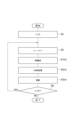
- FIG. 2 is a flow chart of an image processing method.
- FIG. 3 is a diagram showing the sequence of the image processing method of the first mode.
- FIG. 4 is a diagram showing phantom images (correct images), showing (a) a cross-sectional image and (b) a cross-sectional image.
- FIG. 5 is a diagram showing phantom images (correct images), showing (a) an image of a coronal section and (b) an image of a sagittal section.
- FIG. 6 is a diagram showing tomographic images obtained by the image processing method of Comparative Example 1, showing (a) a cross-sectional image and (b) a cross-sectional image.
- FIG. 1 is a diagram showing the configuration of a radiation tomography system 1.
- FIG. 2 is a flow chart of an image processing method.
- FIG. 3 is a diagram showing the sequence of the image processing method of the first mode.
- FIG. 7 is a diagram showing tomographic images obtained by the image processing method of Comparative Example 1, showing (a) an image of a coronal section and (b) an image of a sagittal section.
- FIG. 8 is a diagram showing tomographic images obtained by the image processing method of Comparative Example 2, showing (a) a cross-sectional image and (b) a cross-sectional image.
- FIG. 9 is a diagram showing tomographic images obtained by the image processing method of Comparative Example 2, showing (a) an image of a coronal section and (b) an image of a sagittal section.
- FIG. 10 is a diagram showing tomographic images obtained by the image processing method of the example, showing (a) a cross-sectional image and (b) a cross-sectional image.
- FIG. 11 is a diagram showing tomographic images obtained by the image processing method of the example, showing (a) an image of a coronal section and (b) an image of a sagittal section.
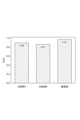
- FIG. 12 is a graph showing PSNR of tomographic images of Comparative Examples 1 and 2 and Example.
- FIG. 13 is a graph showing CRC of tomographic images of Comparative Examples 1 and 2 and Example.
- FIG. 14 is a diagram showing the sequence of the image processing method of the second mode.
- FIG. 1 is a diagram showing the configuration of a radiation tomography system 1.
- FIG. A radiation tomography system 1 includes a radiation tomography apparatus 2 and an image processing apparatus 10 .
- the image processing device 10 includes a reconstruction unit 11 , a CNN processing unit 12 , an updating unit 13 and a storage unit 14 .
- the image processing apparatus 10 also includes an input unit (for example, a keyboard or a mouse) that receives input from an operator, and a display unit (for example, a liquid crystal display) that displays images and the like.
- an input unit for example, a keyboard or a mouse
- a display unit for example, a liquid crystal display
- the radiation tomography apparatus 2 is a device that collects list data for reconstructing a tomographic image of a subject.
- the radiation tomography apparatus 2 includes a PET apparatus and a SPECT apparatus. In the following description, the radiation tomography apparatus 2 is assumed to be a PET apparatus.
- the radiation tomography apparatus 2 includes a detection unit having a large number of small radiation detectors arranged around the measurement space in which the subject is placed.
- the radiation tomography apparatus 2 detects photon pairs with an energy of 511 keV generated by pair annihilation of electrons and positrons in the subject into which a positron emission isotope (RI radiation source) is injected by a detection unit by a coincidence counting method, This coincidence counting information is accumulated. Then, the radiation tomography apparatus 2 outputs to the image processing apparatus 10 a list data in which a large amount of accumulated coincidence counting information is arranged in time series.
- RI radiation source positron emission isotope
- the list data includes identification information and detection time information of a pair of radiation detectors that have coincidentally counted photon pairs.
- the list data further includes detection time difference information (TOF information) of a pair of radiation detectors, photon interaction depth information (DOI information) in the radiation detectors, and energy information of photons detected by the radiation detectors.
- TOF information detection time difference information
- DOI information photon interaction depth information
- energy information of photons detected by the radiation detectors may also include
- the storage unit 14 stores list data collected by the radiation tomography apparatus 2 .
- the storage unit 14 also stores programs for causing the reconstruction unit 11, the CNN processing unit 12, and the update unit 13 to execute respective processes.
- the reconstruction unit 11, the CNN processing unit 12, and the updating unit 13 use the programs and list data stored in the storage unit 14 to create a tomographic image of the subject.
- the reconstruction unit 11 performs processing according to the list mode iterative reconstruction method (see Non-Patent Document 2) to create the first image.
- LM-MLEM Maximum Likelihood Expectation Maximization
- LM-OSEM Organic Subset EM
- LM-DRAMA Dynamic Row Action Maximum Likelihood Algorithm
- the CNN processing unit 12 performs processing based on DIP technology (see Non-Patent Document 1) to create a second image.
- DIP technology see Non-Patent Document 1
- input information is input to the CNN, the second image is created by the CNN, and the CNN is trained.
- the input information to be input to the CNN may be morphological information of the subject, an MRI image or CT image of the subject, or a random noise image.
- the update unit 13 updates the third image based on the first image and the second image. Details of each process of the reconstruction unit 11, the CNN processing unit 12, and the updating unit 13 will be described later.
- the storage unit 14 also stores input information input to the CNN, and also stores the first, second and third images. Starting from a certain initial state, the image processing apparatus 10 repeatedly performs each process of the reconstruction unit 11, the CNN processing unit 12, and the updating unit 13 to create a tomographic image of the subject.
- FIG. 2 is a flowchart of the image processing method.
- the image processing method includes a reconstruction step S ⁇ b>1 performed by the reconstruction unit 11 , a CNN processing step S ⁇ b>2 performed by the CNN processing unit 12 , and an update step S ⁇ b>3 performed by the update unit 13 .
- the reconstruction step S1, the CNN processing step S2, and the update step S3 are repeated multiple times (N times) to create a tomographic image of the subject.
- step S4 the value of parameter n is set to the initial value 0.
- step S5 the value of the parameter n is incremented by one.
- step S5 a reconstruction step S1, a CNN processing step S2 and an update step S3 are performed.
- step S6 the value of the parameter n and N are compared, and if n is determined to be smaller than N, the process returns to step S5. If it is determined in step S6 that n has reached N, the repetitive processing is terminated and a tomographic image of the subject is acquired.
- the n-th reconstruction step S1 is called the reconstruction step S1(n)
- the n-th CNN processing step S2 is called the CNN processing step S2(n)
- the n-th reconstruction step S2 is called the CNN processing step S2(n).
- the update step S3 performed n times is called an update step S3(n).
- n is an integer of 1 or more and N or less.
- the list data U is formulated as in the following (1) formula.
- t is a number representing a coincidence counting event.
- T is the total number of events.
- i(t) represents a number identifying the detector pair that detected the tth event.
- x is a tomographic image.
- x) is the likelihood representing the probability that the list data U is observed from the tomographic image x.
- z is input information input to CNN.
- ⁇ is a parameter representing the learning state of the CNN, such as a connection weight, and changes as the learning of the CNN progresses.
- f ⁇ (z) is an image output from a CNN whose learning state is ⁇ when input information z is input to the CNN.
- the problem is to optimize the tomographic image x and the CNN parameter ⁇ so that x) is high.
- the first mode is processing based on the Alternating Direction Method of Multipliers (ADMM method).
- the second mode is a process based on Forward Backward Splitting (FBS method).
- the FBS method also includes the De Pierro method as its special mode. Details of the image processing methods of the first and second modes will be described below.
- the constrained optimization problem of the above equation (2) is rewritten based on the extended Lagrangian function method and then solved by the ADMM method.
- the constraint in the above equation (2) is replaced with a regularization term, and the constrained optimization problem of the above equation (2) is rewritten as the unconstrained optimization problem of the following equation (3).
- ⁇ is a positive constant that adjusts the strength of regularization.
- ⁇ is called the Lagrangian multiplier or dual variable, and is referred to as the "third image" in the following description.
- ADMM solves the unconstrained optimization problem of equation (3) by repeating the processes of equations (4) to (6) below.
- FIG. 3 is a diagram showing the sequence of the image processing method of the first mode.
- the CNN learning state ⁇ (0) Prior to the iterative process, the CNN learning state ⁇ (0) , the first image x (0) , the second image f ⁇ (0) (z), and the third image ⁇ (0) are initialized.
- the second image f ⁇ (0) (z) is an image output from the CNN when the input information z is input to the CNN in the initial learning state ⁇ (0) .
- the first image x (n-1) is updated once based on the list data U by the list mode iterative reconstruction method according to the above equation (4).
- the obtained image is the difference between the second image f ⁇ (n-1) (z) and the third image ⁇ (n-1) (f ⁇ (n-1) (z) ⁇ (n-1) )
- a new first image x (n) is created by repeating the process of approximating to .
- the input information z is input to the CNN according to the above equation (5), the CNN creates the second image f ⁇ (n) (z), and the created second image f ⁇ (n) (z) is generated.
- Train the CNN so that the two images f ⁇ (n) (z) approach the sum of the first image x (n) and the third image ⁇ (n-1) (x (n) + ⁇ (n-1) )
- ⁇ (n) be the learning state of the CNN after this learning.
- the first image x and the second image f ⁇ (z) are not optimized at the same time, but the first image x and the second image f ⁇ (z) are optimized alternately. It is easy to solve the problem. Further, the processing of the reconstruction step S1 by the reconstruction unit 11 and the processing of the CNN processing step S2 by the CNN processing unit 12 can be performed by conventional methods such as those described in Non-Patent Documents 1 and 2. so it is easy to implement.
- FIGS. 4 to 11 are diagrams showing the results of simulations performed to confirm the effect of the image processing method of the first mode.
- simulation data was created by MC simulation of a head PET device using a digital brain phantom image, and the effect of the image processing method of the first embodiment was confirmed using this data.
- 4 and 5 are diagrams showing phantom images (correct images).
- 4(a) and 4(b) are transverse section images
- FIG. 5(a) is a coronal section image
- FIG. 5(b) is a sagittal section image.
- FIG. 6 and 7 are diagrams showing tomographic images obtained by the image processing method of Comparative Example 1.
- FIG. 6(a) and 6(b) are transverse section images
- FIG. 7(a) is a coronal section image
- FIG. 7(b) is a sagittal section image.
- the tomographic image of Comparative Example 1 was obtained by reconstruction using only the LM-DRAMA iterative update formula of the list mode iterative reconstruction method, and was not subjected to noise reduction processing.
- FIG. 8 and 9 are diagrams showing tomographic images obtained by the image processing method of Comparative Example 2.
- FIG. 8(a) and 8(b) are transverse section images
- FIG. 9(a) is a coronal section image
- FIG. 9(b) is a sagittal section image.
- the tomographic image of Comparative Example 2 was obtained by reducing noise in the reconstructed tomographic image of Comparative Example 1 using the DIP technique.
- the number of CNN parameter updates was set to 20 times. MRI images were used as input information to the CNN.
- 10 and 11 are diagrams showing tomographic images obtained by the image processing method of the example.
- 10(a) and 10(b) are transverse section images
- FIG. 11(a) is a coronal section image
- FIG. 11(b) is a sagittal section image.
- An MRI image was used as input information z to the CNN.
- the number of repetitions in the reconstruction step S1 is set to 2
- the number of repetitions of CNN learning in the CNN processing step S2 is set to 20
- the total number of repetitions N is set to 200.
- the tomographic images obtained by the image processing method of the example have little noise and the structure of the cerebral cortex is well restored.
- FIG. 12 is a graph showing PSNR of tomographic images of Comparative Examples 1 and 2 and Example.
- PSNR is the peak signal-to-noise ratio [in dB], which is a measure of noise.
- FIG. 13 is a graph showing CRC of tomographic images of Comparative Examples 1 and 2 and Example.
- CRC is the tumor contrast recovery coefficient, which is a quantitative measure.
- the tomographic image of the example has higher PSNR and CRC than the tomographic images of Comparative Examples 1 and 2, and the CRC is close to the ideal value of 1.0.
- the image processing method of the example can generate a tomographic image with high quantitativeness while suppressing an increase in noise artifacts.
- the constrained optimization problem of the above equation (2) is solved by the FBS method based on the framework of the maximum a posteriori (MAP) estimation method.
- MAP estimation method the constrained optimization problem of the above equation (2) is rewritten as the unconstrained optimization problem of the following equation (7).
- the FBS solves the unconstrained optimization problem of equation (7) by repeating the processes of equations (8) to (11) below.
- ⁇ is a previously given parameter image.
- ⁇ is an image representing the sensitivity of the detector for each pixel.
- sensitivity image ⁇ is expressed by the following equation (12).
- FIG. 14 is a diagram showing the sequence of the image processing method of the second mode. Prior to the iterative process, the CNN learning state ⁇ (0) and the third image x (0) are initialized.
- the third image x (n-1) is updated based on the list data U by the list mode iterative reconstruction method according to the above equation (8). Create the first image x ML (n) .
- the input information z is input to the CNN according to the above equation (9), the CNN creates the second image f ⁇ (n) (z), and the created second image f ⁇ (n) (z) is generated.
- the CNN is trained so that the second image f ⁇ (n) (z) approaches the third image x (n ⁇ 1) .
- ⁇ (n) be the learning state of the CNN after this learning.
- the reconstruction step S1 When the reconstruction step S1, the CNN processing step S2, and the updating step S3 are repeated N times, the first image x ML (N) , the second image f ⁇ (N) (z), and the Any one of the 3 images x (N) is set as a tomographic image of the subject.
- the reconstruction step S1(n) and the CNN processing step S2(n) may be performed in any order or in parallel.
- the processing contents of each of the reconstruction step S1, the CNN processing step S2, and the update step S3 are the same as described above.
- the first image x ML and the second image f ⁇ (z) are optimized separately. So it is easy to solve the problem.
- the processing of the reconstruction step S1 by the reconstruction unit 11 and the processing of the CNN processing step S2 by the CNN processing unit 12 can be performed by conventional methods such as those described in Non-Patent Documents 1 and 2. so it is easy to implement.
- the tomographic image obtained by the image processing method of the second aspect also has little noise and the structure of the cerebral cortex is well restored, as in the case of the first aspect. Even in the second aspect, it is possible to generate a tomographic image with high quantitativeness while suppressing an increase in noise artifacts.
- the radiation tomography apparatus 2 is a PET apparatus in the above embodiment, it may be a SPECT apparatus.
- An image processing apparatus is an image processing apparatus that creates a tomographic image based on list data collected by a radiation tomography apparatus, and includes: (1) a list mode by a list mode iterative reconstruction method; (2 ) Input information to the convolutional neural network to generate a second image by the convolutional neural network, and train the convolutional neural network so that the generated second image approaches the sum of the first image and the third image. and (3) an updating unit for updating the third image based on the first image and the second image, the learning state of the convolutional neural network, the first image, the second image, and the third image.
- An image processing apparatus is an image processing apparatus that creates a tomographic image based on list data collected by a radiation tomography apparatus, and includes: (1) a list mode by a list mode iterative reconstruction method; (2) inputting input information to a convolutional neural network to generate a second image by means of the convolutional neural network; A CNN processing unit that trains a convolutional neural network so that the created second image approaches the third image, and (3) an updating unit that updates the third image based on the first image and the second image, Starting from the learning state of the convolutional neural network and the initial state of each of the third image, the reconstruction unit creates the first image, the CNN processing unit creates the second image and trains the convolutional neural network, and the updating unit creates the third image. The image is repeatedly updated, and any one of the first, second, and third images obtained by these repeated processes is used as a tomographic image.
- the CNN processing section may be configured to input an image representing the morphological information of the subject to the convolutional neural network as input information.
- the CNN processing unit may be configured to input the MRI image of the subject as input information to the convolutional neural network. Further, the CNN processing unit may be configured to input the CT image of the subject as input information to the convolutional neural network.
- the CNN processing unit may be configured to input the random noise image as input information to the convolutional neural network.
- the radiation tomography system includes a radiation tomography apparatus that collects list data for reconstructing a tomographic image of a subject, and creates a tomographic image based on the list data collected by the radiation tomography apparatus. and an image processing device configured as described above.
- the image processing method is an image processing method for creating a tomographic image based on list data collected by a radiation tomography apparatus, comprising: (1) list mode iterative reconstruction method (2 ) Input information to the convolutional neural network to generate a second image by the convolutional neural network, and train the convolutional neural network so that the generated second image approaches the sum of the first image and the third image.
- the image processing method is an image processing method for creating a tomographic image based on list data collected by a radiation tomography apparatus, comprising: (1) List mode iterative reconstruction method (2) inputting input information to a convolutional neural network to generate a second image by means of the convolutional neural network; A CNN processing step for learning a convolutional neural network so that the created second image approaches the third image; and (3) an update step for updating the third image based on the first image and the second image, Starting from the training state of the convolutional neural network and the initial state of the third image respectively, the construction of the first image in the reconstruction step, the construction of the second image in the CNN processing step and the training of the convolutional neural network, and the third image in the update step. The image is repeatedly updated, and any one of the first, second, and third images obtained by these repeated processes is used as a tomographic image.
- an image representing the morphological information of the subject may be input to the convolutional neural network as input information.
- the MRI image of the subject may be input to the convolutional neural network as input information.
- the CT image of the subject may be input to the convolutional neural network as input information.
- a random noise image may be input to the convolutional neural network as input information.
- the present invention can be used as an image processing apparatus and an image processing method capable of creating a noise-reduced tomographic image based on list data collected by a radiation tomography apparatus.
- Radiation tomography system 1... Radiation tomography system, 2... Radiation tomography apparatus, 10... Image processing apparatus, 11... Reconstruction unit, 12... CNN processing unit, 13... Update unit, 14... Storage unit.
Landscapes
- Health & Medical Sciences (AREA)
- Life Sciences & Earth Sciences (AREA)
- Engineering & Computer Science (AREA)
- Medical Informatics (AREA)
- Physics & Mathematics (AREA)
- Molecular Biology (AREA)
- High Energy & Nuclear Physics (AREA)
- Biophysics (AREA)
- Heart & Thoracic Surgery (AREA)
- Public Health (AREA)
- Veterinary Medicine (AREA)
- General Health & Medical Sciences (AREA)
- Nuclear Medicine, Radiotherapy & Molecular Imaging (AREA)
- Optics & Photonics (AREA)
- Pathology (AREA)
- Radiology & Medical Imaging (AREA)
- Biomedical Technology (AREA)
- Animal Behavior & Ethology (AREA)
- Surgery (AREA)
- Theoretical Computer Science (AREA)
- General Physics & Mathematics (AREA)
- Computer Vision & Pattern Recognition (AREA)
- Spectroscopy & Molecular Physics (AREA)
- Pulmonology (AREA)
- Image Processing (AREA)
- Nuclear Medicine (AREA)
- Apparatus For Radiation Diagnosis (AREA)
- Algebra (AREA)
- Mathematical Analysis (AREA)
- Mathematical Optimization (AREA)
- Mathematical Physics (AREA)
- Pure & Applied Mathematics (AREA)
Abstract
Description













Claims (13)
- 放射線断層撮影装置により収集されたリストデータに基づいて断層画像を作成する画像処理装置であって、
リストモード逐次近似再構成法により前記リストデータに基づいて第1画像の更新を行って得られた画像を第2画像と第3画像との差に近づける処理を繰り返すことにより、新たな第1画像を作成する再構成部と、
畳み込みニューラルネットワークに入力情報を入力させて前記畳み込みニューラルネットワークにより第2画像を作成し、この作成した第2画像が前記第1画像と前記第3画像との和に近づくように前記畳み込みニューラルネットワークを学習させるCNN処理部と、
前記第1画像および前記第2画像に基づいて前記第3画像を更新する更新部と、
を備え、
前記畳み込みニューラルネットワークの学習状態、前記第1画像、前記第2画像および前記第3画像それぞれの初期状態から始めて、前記再構成部による前記第1画像の作成、前記CNN処理部による前記第2画像の作成および前記畳み込みニューラルネットワークの学習、ならびに、前記更新部による前記第3画像の更新を繰り返し行って、これらの繰り返し処理で得られた前記第1画像および前記第2画像の何れかを前記断層画像とする、画像処理装置。 - 放射線断層撮影装置により収集されたリストデータに基づいて断層画像を作成する画像処理装置であって、
リストモード逐次近似再構成法により前記リストデータに基づいて第3画像の更新を行うことにより、第1画像を作成する再構成部と、
畳み込みニューラルネットワークに入力情報を入力させて前記畳み込みニューラルネットワークにより第2画像を作成し、この作成した第2画像が前記第3画像に近づくように前記畳み込みニューラルネットワークを学習させるCNN処理部と、
前記第1画像および前記第2画像に基づいて前記第3画像を更新する更新部と、
を備え、
前記畳み込みニューラルネットワークの学習状態および前記第3画像それぞれの初期状態から始めて、前記再構成部による前記第1画像の作成、前記CNN処理部による前記第2画像の作成および前記畳み込みニューラルネットワークの学習、ならびに、前記更新部による前記第3画像の更新を繰り返し行って、これらの繰り返し処理で得られた前記第1画像、前記第2画像および前記第3画像の何れかを前記断層画像とする、画像処理装置。 - 前記CNN処理部は、被検体の形態情報を表す画像を前記入力情報として前記畳み込みニューラルネットワークに入力させる、請求項1または2に記載の画像処理装置。
- 前記CNN処理部は、被検体のMRI画像を前記入力情報として前記畳み込みニューラルネットワークに入力させる、請求項1または2に記載の画像処理装置。
- 前記CNN処理部は、被検体のCT画像を前記入力情報として前記畳み込みニューラルネットワークに入力させる、請求項1または2に記載の画像処理装置。
- 前記CNN処理部は、ランダムノイズ画像を前記入力情報として前記畳み込みニューラルネットワークに入力させる、請求項1または2に記載の画像処理装置。
- 被検体の断層画像を再構成するためのリストデータを収集する放射線断層撮影装置と、
前記放射線断層撮影装置により収集されたリストデータに基づいて断層画像を作成する請求項1~6の何れか1項に記載の画像処理装置と、
を備える、放射線断層撮影システム。 - 放射線断層撮影装置により収集されたリストデータに基づいて断層画像を作成する画像処理方法であって、
リストモード逐次近似再構成法により前記リストデータに基づいて第1画像の更新を行って得られた画像を第2画像と第3画像との差に近づける処理を繰り返すことにより、新たな第1画像を作成する再構成ステップと、
畳み込みニューラルネットワークに入力情報を入力させて前記畳み込みニューラルネットワークにより第2画像を作成し、この作成した第2画像が前記第1画像と前記第3画像との和に近づくように前記畳み込みニューラルネットワークを学習させるCNN処理ステップと、
前記第1画像および前記第2画像に基づいて前記第3画像を更新する更新ステップと、
を備え、
前記畳み込みニューラルネットワークの学習状態、前記第1画像、前記第2画像および前記第3画像それぞれの初期状態から始めて、前記再構成ステップにおける前記第1画像の作成、前記CNN処理ステップにおける前記第2画像の作成および前記畳み込みニューラルネットワークの学習、ならびに、前記更新ステップにおける前記第3画像の更新を繰り返し行って、これらの繰り返し処理で得られた前記第1画像および前記第2画像の何れかを前記断層画像とする、画像処理方法。 - 放射線断層撮影装置により収集されたリストデータに基づいて断層画像を作成する画像処理方法であって、
リストモード逐次近似再構成法により前記リストデータに基づいて第3画像の更新を行うことにより、第1画像を作成する再構成ステップと、
畳み込みニューラルネットワークに入力情報を入力させて前記畳み込みニューラルネットワークにより第2画像を作成し、この作成した第2画像が前記第3画像に近づくように前記畳み込みニューラルネットワークを学習させるCNN処理ステップと、
前記第1画像および前記第2画像に基づいて前記第3画像を更新する更新ステップと、
を備え、
前記畳み込みニューラルネットワークの学習状態および前記第3画像それぞれの初期状態から始めて、前記再構成ステップにおける前記第1画像の作成、前記CNN処理ステップにおける前記第2画像の作成および前記畳み込みニューラルネットワークの学習、ならびに、前記更新ステップにおける前記第3画像の更新を繰り返し行って、これらの繰り返し処理で得られた前記第1画像、前記第2画像および前記第3画像の何れかを前記断層画像とする、画像処理方法。 - 前記CNN処理ステップにおいて、被検体の形態情報を表す画像を前記入力情報として前記畳み込みニューラルネットワークに入力させる、請求項8または9に記載の画像処理方法。
- 前記CNN処理ステップにおいて、被検体のMRI画像を前記入力情報として前記畳み込みニューラルネットワークに入力させる、請求項8または9に記載の画像処理方法。
- 前記CNN処理ステップにおいて、被検体のCT画像を前記入力情報として前記畳み込みニューラルネットワークに入力させる、請求項8または9に記載の画像処理方法。
- 前記CNN処理ステップにおいて、ランダムノイズ画像を前記入力情報として前記畳み込みニューラルネットワークに入力させる、請求項8または9に記載の画像処理方法。
Priority Applications (3)
| Application Number | Priority Date | Filing Date | Title |
|---|---|---|---|
| DE112023000780.2T DE112023000780T5 (de) | 2022-02-02 | 2023-01-30 | Bildverarbeitungsvorrichtung und Bildverarbeitungsverfahren |
| US18/833,003 US20250157099A1 (en) | 2022-02-02 | 2023-01-30 | Image processing device and image processing method |
| CN202380019854.1A CN118647904A (zh) | 2022-02-02 | 2023-01-30 | 图像处理装置和图像处理方法 |
Applications Claiming Priority (2)
| Application Number | Priority Date | Filing Date | Title |
|---|---|---|---|
| JP2022-014768 | 2022-02-02 | ||
| JP2022014768A JP2023112818A (ja) | 2022-02-02 | 2022-02-02 | 画像処理装置および画像処理方法 |
Publications (1)
| Publication Number | Publication Date |
|---|---|
| WO2023149403A1 true WO2023149403A1 (ja) | 2023-08-10 |
Family
ID=87552365
Family Applications (1)
| Application Number | Title | Priority Date | Filing Date |
|---|---|---|---|
| PCT/JP2023/002910 Ceased WO2023149403A1 (ja) | 2022-02-02 | 2023-01-30 | 画像処理装置および画像処理方法 |
Country Status (5)
| Country | Link |
|---|---|
| US (1) | US20250157099A1 (ja) |
| JP (1) | JP2023112818A (ja) |
| CN (1) | CN118647904A (ja) |
| DE (1) | DE112023000780T5 (ja) |
| WO (1) | WO2023149403A1 (ja) |
Citations (6)
| Publication number | Priority date | Publication date | Assignee | Title |
|---|---|---|---|---|
| JP2020036877A (ja) * | 2018-08-06 | 2020-03-12 | ゼネラル・エレクトリック・カンパニイ | 反復的画像再構成フレームワーク |
| JP2020128882A (ja) * | 2019-02-07 | 2020-08-27 | 浜松ホトニクス株式会社 | 画像処理装置および画像処理方法 |
| WO2020201755A1 (en) * | 2019-04-03 | 2020-10-08 | King's College London | Image reconstruction |
| JP2021018109A (ja) * | 2019-07-18 | 2021-02-15 | キヤノンメディカルシステムズ株式会社 | 医用画像処理装置、医用画像診断装置及び核医学診断装置 |
| US20210074036A1 (en) * | 2018-03-23 | 2021-03-11 | Memorial Sloan Kettering Cancer Center | Deep encoder-decoder models for reconstructing biomedical images |
| JP2021117866A (ja) * | 2020-01-29 | 2021-08-10 | 浜松ホトニクス株式会社 | 画像処理装置および画像処理方法 |
-
2022
- 2022-02-02 JP JP2022014768A patent/JP2023112818A/ja active Pending
-
2023
- 2023-01-30 US US18/833,003 patent/US20250157099A1/en active Pending
- 2023-01-30 DE DE112023000780.2T patent/DE112023000780T5/de active Pending
- 2023-01-30 WO PCT/JP2023/002910 patent/WO2023149403A1/ja not_active Ceased
- 2023-01-30 CN CN202380019854.1A patent/CN118647904A/zh active Pending
Patent Citations (6)
| Publication number | Priority date | Publication date | Assignee | Title |
|---|---|---|---|---|
| US20210074036A1 (en) * | 2018-03-23 | 2021-03-11 | Memorial Sloan Kettering Cancer Center | Deep encoder-decoder models for reconstructing biomedical images |
| JP2020036877A (ja) * | 2018-08-06 | 2020-03-12 | ゼネラル・エレクトリック・カンパニイ | 反復的画像再構成フレームワーク |
| JP2020128882A (ja) * | 2019-02-07 | 2020-08-27 | 浜松ホトニクス株式会社 | 画像処理装置および画像処理方法 |
| WO2020201755A1 (en) * | 2019-04-03 | 2020-10-08 | King's College London | Image reconstruction |
| JP2021018109A (ja) * | 2019-07-18 | 2021-02-15 | キヤノンメディカルシステムズ株式会社 | 医用画像処理装置、医用画像診断装置及び核医学診断装置 |
| JP2021117866A (ja) * | 2020-01-29 | 2021-08-10 | 浜松ホトニクス株式会社 | 画像処理装置および画像処理方法 |
Non-Patent Citations (1)
| Title |
|---|
| GONG KUANG; GUAN JIAHUI; KIM KYUNGSANG; ZHANG XUEZHU; YANG JAEWON; SEO YOUNGHO; EL FAKHRI GEORGES; QI JINYI; LI QUANZHENG: "Iterative PET Image Reconstruction Using Convolutional Neural Network Representation", IEEE TRANSACTIONS ON MEDICAL IMAGING, IEEE, USA, vol. 38, no. 3, 1 March 2019 (2019-03-01), USA, pages 675 - 685, XP011712614, ISSN: 0278-0062, DOI: 10.1109/TMI.2018.2869871 * |
Also Published As
| Publication number | Publication date |
|---|---|
| CN118647904A (zh) | 2024-09-13 |
| JP2023112818A (ja) | 2023-08-15 |
| DE112023000780T5 (de) | 2025-03-27 |
| US20250157099A1 (en) | 2025-05-15 |
Similar Documents
| Publication | Publication Date | Title |
|---|---|---|
| US11893660B2 (en) | Image processing device and image processing method | |
| CN103501702A (zh) | 医用图像处理装置、医用图像处理方法 | |
| US12444098B2 (en) | Image processing device and image processing method | |
| Zhang et al. | Deep generalized learning model for PET image reconstruction | |
| Gautier et al. | Bimodal PET/MRI generative reconstruction based on VAE architectures | |
| Galve et al. | Super-iterative image reconstruction in PET | |
| Jiao et al. | Fast PET reconstruction using multi-scale fully convolutional neural networks | |
| Phung-Ngoc et al. | Joint reconstruction of activity and attenuation in PET by diffusion posterior sampling in wavelet coefficient space | |
| Whiteley et al. | FastPET: Near real-time PET reconstruction from histo-images using a neural network | |
| Rashid et al. | Optimization of PET Image Reconstruction for Enhanced Image Quality in Various Tasks Using a Conventional PET Scanner | |
| JP6974159B2 (ja) | 画像処理装置および画像処理方法 | |
| JP2023112818A (ja) | 画像処理装置および画像処理方法 | |
| CN105631908A (zh) | 一种pet图像重建方法和装置 | |
| JP6495615B2 (ja) | 画像処理装置および画像処理方法 | |
| Anthoine et al. | Some proximal methods for CBCT and PET tomography | |
| Tian et al. | LM-SPD-Net: list-mode TOF-PET image reconstruction using stochastic primal-dual network | |
| WO2021153555A1 (ja) | 減弱分布画像作成装置、画像処理装置、放射線断層撮影システム、減弱分布画像作成方法、画像処理方法 | |
| Chen et al. | Enhancing low-dose ct image reconstruction by integrating supervised and unsupervised learning | |
| Kaprélian et al. | Towards Deep-Learning Partial Volume Correction for SPECT | |
| JP6986961B2 (ja) | 画像処理装置および画像処理方法 | |
| CN120051712A (zh) | 图像处理装置和图像处理方法 | |
| JP2023173737A (ja) | 画像処理装置および画像処理方法 | |
| JP2024157164A (ja) | 画像処理装置および画像処理方法 |
Legal Events
| Date | Code | Title | Description |
|---|---|---|---|
| 121 | Ep: the epo has been informed by wipo that ep was designated in this application |
Ref document number: 23749719 Country of ref document: EP Kind code of ref document: A1 |
|
| WWE | Wipo information: entry into national phase |
Ref document number: 18833003 Country of ref document: US |
|
| WWE | Wipo information: entry into national phase |
Ref document number: 202380019854.1 Country of ref document: CN |
|
| WWE | Wipo information: entry into national phase |
Ref document number: 112023000780 Country of ref document: DE |
|
| 122 | Ep: pct application non-entry in european phase |
Ref document number: 23749719 Country of ref document: EP Kind code of ref document: A1 |
|
| WWP | Wipo information: published in national office |
Ref document number: 112023000780 Country of ref document: DE |
|
| WWP | Wipo information: published in national office |
Ref document number: 18833003 Country of ref document: US |