WO2023149062A1 - 膨張弁 - Google Patents
膨張弁 Download PDFInfo
- Publication number
- WO2023149062A1 WO2023149062A1 PCT/JP2022/043684 JP2022043684W WO2023149062A1 WO 2023149062 A1 WO2023149062 A1 WO 2023149062A1 JP 2022043684 W JP2022043684 W JP 2022043684W WO 2023149062 A1 WO2023149062 A1 WO 2023149062A1
- Authority
- WO
- WIPO (PCT)
- Prior art keywords
- valve body
- valve
- axis
- insertion portion
- expansion valve
- Prior art date
- Legal status (The legal status is an assumption and is not a legal conclusion. Google has not performed a legal analysis and makes no representation as to the accuracy of the status listed.)
- Ceased
Links
Images









Classifications
-
- F—MECHANICAL ENGINEERING; LIGHTING; HEATING; WEAPONS; BLASTING
- F25—REFRIGERATION OR COOLING; COMBINED HEATING AND REFRIGERATION SYSTEMS; HEAT PUMP SYSTEMS; MANUFACTURE OR STORAGE OF ICE; LIQUEFACTION SOLIDIFICATION OF GASES
- F25B—REFRIGERATION MACHINES, PLANTS OR SYSTEMS; COMBINED HEATING AND REFRIGERATION SYSTEMS; HEAT PUMP SYSTEMS
- F25B41/00—Fluid-circulation arrangements
- F25B41/30—Expansion means; Dispositions thereof
- F25B41/31—Expansion valves
- F25B41/33—Expansion valves with the valve member being actuated by the fluid pressure, e.g. by the pressure of the refrigerant
- F25B41/335—Expansion valves with the valve member being actuated by the fluid pressure, e.g. by the pressure of the refrigerant via diaphragms
-
- F—MECHANICAL ENGINEERING; LIGHTING; HEATING; WEAPONS; BLASTING
- F16—ENGINEERING ELEMENTS AND UNITS; GENERAL MEASURES FOR PRODUCING AND MAINTAINING EFFECTIVE FUNCTIONING OF MACHINES OR INSTALLATIONS; THERMAL INSULATION IN GENERAL
- F16K—VALVES; TAPS; COCKS; ACTUATING-FLOATS; DEVICES FOR VENTING OR AERATING
- F16K1/00—Lift valves or globe valves, i.e. cut-off apparatus with closure members having at least a component of their opening and closing motion perpendicular to the closing faces
- F16K1/32—Details
- F16K1/34—Cutting-off parts, e.g. valve members, seats
- F16K1/36—Valve members
-
- F—MECHANICAL ENGINEERING; LIGHTING; HEATING; WEAPONS; BLASTING
- F16—ENGINEERING ELEMENTS AND UNITS; GENERAL MEASURES FOR PRODUCING AND MAINTAINING EFFECTIVE FUNCTIONING OF MACHINES OR INSTALLATIONS; THERMAL INSULATION IN GENERAL
- F16K—VALVES; TAPS; COCKS; ACTUATING-FLOATS; DEVICES FOR VENTING OR AERATING
- F16K47/00—Means in valves for absorbing fluid energy
- F16K47/01—Damping of valve members
-
- F—MECHANICAL ENGINEERING; LIGHTING; HEATING; WEAPONS; BLASTING
- F25—REFRIGERATION OR COOLING; COMBINED HEATING AND REFRIGERATION SYSTEMS; HEAT PUMP SYSTEMS; MANUFACTURE OR STORAGE OF ICE; LIQUEFACTION SOLIDIFICATION OF GASES
- F25B—REFRIGERATION MACHINES, PLANTS OR SYSTEMS; COMBINED HEATING AND REFRIGERATION SYSTEMS; HEAT PUMP SYSTEMS
- F25B2341/00—Details of ejectors not being used as compression device; Details of flow restrictors or expansion valves
- F25B2341/06—Details of flow restrictors or expansion valves
- F25B2341/068—Expansion valves combined with a sensor
- F25B2341/0683—Expansion valves combined with a sensor the sensor is disposed in the suction line and influenced by the temperature or the pressure of the suction gas
Definitions
- the present invention relates to expansion valves.
- a valve body of such an expansion valve has an inlet port into which high-pressure refrigerant is introduced and a valve chamber communicating with the inlet port.
- the spherical valve body arranged in the valve chamber is arranged to face the valve seat of the valve hole that opens into the valve chamber.
- the valve body is supported by a support member arranged in the valve chamber, and is biased toward the valve seat by a coil spring installed between an adjusting screw attached to the valve body and the support member.
- the valve body is driven by the power element via the valve stem to control the opening of the throttle passage between the valve seat and the valve seat. Also, the refrigerant that has passed through the valve hole is sent from the outlet port to the evaporator side.
- the high-pressure refrigerant fed into the inlet port of the expansion valve may experience pressure fluctuations (pulsation) due to the operation of the compressor, which may cause the valve body to vibrate and generate abnormal noise. Therefore, an anti-vibration spring for preventing vibration of the valve body has been proposed (see, for example, Patent Document 1).
- the spherical valve body is welded to a supporting member called a valve body support, and the anti-vibration spring is sandwiched between the valve body support and the coil spring. assembly is performed.
- an object of the present invention is to provide an expansion valve that can achieve further weight reduction and cost reduction while using the same materials as conventional ones, for example.
- the expansion valve a valve body with a valve seat in the valve chamber; a valve body that blocks passage of fluid by being seated on the valve seat and permits passage of the fluid by separating from the valve seat; a valve body support connected to the valve body, the valve body support including an insertion section and a flange protruding from the insertion section in a direction orthogonal to the axis; a coil spring in which the insertion part is inserted inside and biases the valve body toward the valve seat via the valve body support; a vibration isolating member sandwiched between the flange and the coil spring;
- the vibration isolating member includes a base portion having an opening through which the insertion portion penetrates, and a plurality of leg pieces extending from the base portion and abutting against the inner wall of the valve chamber, At least one of the outer circumference of the insertion portion and the inner circumference of the opening is non-circular in a cross section perpendicular to the axis of the
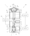
- FIG. 1 is a schematic cross-sectional view schematically showing an example in which the expansion valve 1 of the first embodiment is applied to a refrigerant circulation system.
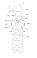
- FIG. 2 is an exploded perspective view of the valve body, the valve body support, the valve body anti-vibration spring, and the coil spring.
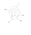
- FIG. 3 is a perspective view of the valve body and the valve body support as seen from below.
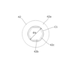
- FIG. 4 is a bottom view of the valve body and the valve body support.
- FIG. 5 is a top view of the coil spring.
- FIG. 6 is a perspective view showing the valve body, the valve body support according to the second embodiment, the valve body anti-vibration spring, and the coil spring in an exploded state.
- FIG. 1 is a schematic cross-sectional view schematically showing an example in which the expansion valve 1 of the first embodiment is applied to a refrigerant circulation system.
- FIG. 2 is an exploded perspective view of the valve body, the valve body support, the valve body anti-vibration spring, and the coil
- FIG. 7 is a bottom perspective view of the valve body and the valve body support according to the second embodiment.
- FIG. 8 is a bottom view of the valve body and the valve body support according to the second embodiment.
- FIG. 9 is an exploded perspective view of the valve body, the valve body support according to the third embodiment, the valve body anti-vibration spring, and the coil spring.
- FIG. 10 is a bottom perspective view of the valve body and the valve body support according to the third embodiment.
- FIG. 11 is a bottom view of the valve body 3 and the valve body support according to the third embodiment.
- FIG. 12 is an exploded perspective view showing the valve body 3, the valve body support according to the fourth embodiment, the valve body anti-vibration spring according to the fourth embodiment, and the coil spring.
- FIG. 13 is a top view of the valve body anti-vibration spring.
- FIG. 14 is a bottom perspective view of the valve body and the valve body support according to the fifth embodiment.
- FIG. 15 is a bottom view of the valve body and the valve body support according to the fifth embodiment.
- FIG. 16 is a side view of the valve body and the valve body support according to the modification.
- FIG. 17 is an exploded perspective view showing the valve body 3, the valve body support, the valve body anti-vibration spring according to the sixth embodiment, and the coil spring.
- FIG. 18 is a top view of the valve body anti-vibration spring.
- FIG. 19 is a perspective view showing an exploded state of the valve body, the valve body support according to the seventh embodiment, the valve body anti-vibration spring according to the seventh embodiment, and the coil spring.
- FIG. 20 is a perspective view showing an exploded state of the valve body, the valve body support according to the eighth embodiment, the valve body anti-vibration spring according to the eighth embodiment, and the coil spring. It is an axis-line orthogonal cross-sectional view of a valve body support and a valve body anti-vibration spring according to a modification.
- the direction from the valve body 3 to the operating rod 5 is defined as “upward direction”, and the direction from the operating rod 5 to the valve body 3 is defined as “downward direction”. Therefore, in this specification, the direction from the valve body 3 toward the operating rod 5 is referred to as the "upward direction” regardless of the orientation of the expansion valve 1 .
- "contacting at three or more points along the circumferential direction” means that when the inner circumference and the outer circumference are in point contact, the contact points are 180 degrees in the circumferential direction in the plane perpendicular to the axis.
- the inner circumference and the outer circumference are fixed to each other in the direction perpendicular to the axis, and when the inner circumference and the outer circumference are in line contact, three or more points
- the inner circumference and and the outer periphery are fixed to each other.
- “the minimum inscribed circle diameter is equal to the inner diameter” and “the maximum inscribed circle diameter is equal to the outer diameter” are not only the case where both are completely equal, but also substantially equal (e.g. differ only in ).
- FIG. 1 is a schematic cross-sectional view schematically showing an example in which an expansion valve 1 according to this embodiment is applied to a refrigerant circulation system 100.
- expansion valve 1 is fluidly connected to compressor 101 , condenser 102 and evaporator 104 .
- L be the axis of the expansion valve 1 .
- the expansion valve 1 includes a valve body 2 having a valve chamber VS, a valve body 3, an urging device 4, an operating rod 5, a ring spring 6, and a power element 8.
- L be the axis of the expansion valve 1 .
- the valve body 2 includes a first flow path 21, a second flow path 22 and a return flow path 23 in addition to the valve chamber VS.
- the first flow path 21 is a supply-side flow path, and refrigerant (also referred to as fluid) is supplied to the valve chamber VS through the supply-side flow path.
- the second flow path 22 is a discharge side flow path, and the fluid in the valve chamber VS is discharged to the outside of the expansion valve through the operating rod insertion hole 27 and the discharge side flow path.
- the first flow path 21 and the valve chamber VS are communicated with each other by a connection path 21a having a diameter smaller than that of the first flow path 21 .
- the spherical valve body 3 is arranged inside the valve chamber VS.
- the valve body 3 When the valve body 3 is seated on the annular valve seat 20 of the valve body 2, the first flow path 21 and the second flow path 22 are in a non-communication state.
- the valve body 3 when the valve body 3 is separated from the valve seat 20, the first channel 21 and the second channel 22 are in communication.
- the lower end of the operating rod 5 inserted through the operating rod insertion hole 27 with a gap is in contact with the upper surface of the valve body 3 . Further, the operating rod 5 can press the valve body 3 in the valve opening direction against the biasing force of the biasing device 4 . When the operating rod 5 moves downward, the valve body 3 is separated from the valve seat 20 and the expansion valve 1 is opened.
- the operating rod 5 passes power from the valve body 3 along the axis L through an operating rod insertion hole 27 coaxially formed in the valve body 2, a central hole 28, an annular portion 26, a return passage 23, and a communication passage 2b. It extends to element 8.
- the inner diameter of the annular portion 26 is larger than the inner diameter of the central hole 28 that slidably holds the operating rod 5 .
- An operating rod vibration isolation spring 6 having a vibration isolation function for the operating rod 5 is arranged in the annular portion 26 . Details of the operating rod anti-vibration spring 6 are described in, for example, Japanese Patent Application Laid-Open No. 2018-25332, so description thereof will be omitted here.
- Both the second flow path 22 and the return flow path 23 are located on the low pressure side in the refrigeration cycle, but since the refrigerant passes through the evaporator 104 and receives pressure loss, the former has a relatively high pressure. Therefore, the second channel 22 may be called a high-pressure channel, and the return channel 23 may be called a low-pressure channel.
- the power element 8 is attached to a recess 2 a provided on the top of the valve body 2 .
- the recess 2a communicates with a return passage 23 in the valve body 2 through which the refrigerant from the evaporator 104 passes through the communication passage 2b.
- the power element 8 has a plug 81 , an upper lid member 82 , a diaphragm 83 , a stopper member 84 and a receiving member 86 .
- a hole 82 a is formed at the top of the upper lid member 82 and can be sealed with a plug 81 .
- the diaphragm 83 is made of a thin plate on which a plurality of concentric concave and convex shapes are formed.
- the stopper member 84 has a disk portion and a cylindrical portion coaxially connected to the lower surface of the disk portion, and a fitting hole 84c is formed in the center of the lower end of the cylindrical portion.
- the receiving member 86 has a flange portion having an outer diameter approximately the same as the outer diameter of the upper lid member 82, and a hollow cylindrical portion connected to the lower end of the flange portion. formed.
- the outer peripheral portions of the upper lid member 82, the diaphragm 83, and the flange portion of the receiving member 86 are overlapped, and then the outer peripheral portions are welded by TIG welding, laser welding, plasma welding, or the like. Weld and integrate.
- a working gas is introduced from a hole 82a formed in the upper lid member 82 into a space surrounded by the upper lid member 82 and the diaphragm 83 (referred to as a pressure actuation chamber PA)
- the hole 82a is sealed with a plug 81.
- the plug 81 is fixed to the upper cover member 82 using, for example, projection welding.
- the working gas enclosed in the pressure actuation chamber PA causes the diaphragm 83 to receive pressure in such a manner as to protrude toward the receiving member 86 . It is supported in contact with the upper surface of the member 84 . Since the disc portion of the stopper member 84 is held by the receiving member 86 , the stopper member 84 will not slip out of the power element 8 .
- the upper end of the operating rod 5 is fitted into the fitting hole 84c of the stopper member 84, and the operating rod anti-vibration spring 6 assembled to the valve main body 2 is passed therethrough.
- the operating rod 5 is inserted into the valve body 2 .
- the male thread 86c of the receiving member 86 is screwed into the female thread of the concave portion 2a of the valve body 2, and the power element 8 is fixed to the valve body 2 by screwing.
- the lower space LS of the power element 8 communicates with the return channel 23, that is, has the same internal pressure.
- the biasing device 4 includes a coil spring 41 formed by spirally winding a circular wire, a valve body support 42 attached to the upper end of the coil spring 41 to support the valve body 3 , and the lower end of the coil spring 41 . and a valve body anti-vibration spring (anti-vibration member) 44 .
- the spring receiving member 43 has the function of sealing the valve chamber VS of the valve body 2 and supporting the end of the coil spring 41 that biases the valve body 3 toward the valve seat 20 .
- the spherical valve body 3 is welded to the upper surface of the valve body support 42, and both are integrated.
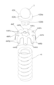
- FIG. 2 is a perspective view showing the valve body 3, the valve body support 42, the valve body anti-vibration spring 44, and the coil spring 41 in an exploded state.
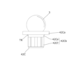
- FIG. 3 is a perspective view of the valve body 3 and the valve body support 42 as seen from below. 4 is a bottom view of the valve body 3 and the valve body support 42.
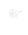
- FIG. 5 is a top view of the coil spring 41.
- the valve body support 42 has a disc-shaped collar portion 42a and a substantially hexagonal prism-shaped insertion portion 42b connected to the lower surface of the collar portion 42a. 42 d of chamfers are formed in the lower end of the insertion part 42b over the perimeter.
- a concave portion 42c is formed in the center of the upper surface of the collar portion 42a that protrudes in the direction orthogonal to the axis line with respect to the inserting portion 42b (that is, has a diameter larger than the minimum circumscribed circle of the inserting portion 42b), and the valve body 3 is fitted into the concave portion 42c. are welded together.
- the axis of the valve body support 42 coincides with the axis L of the expansion valve 1 in the assembled state.
- the valve body support 42 can be formed by press molding, forging, or the like.
- the insertion portion 42b has a hexagonal prism shape (non-circular shape) with a uniform cross section in the direction perpendicular to the axis except for the chamfer 42d, and as shown in FIG. is located on the minimum circumscribed circle C1 with a diameter ⁇ a. For this reason, compared to the case where the insertion portion is cylindrical, the insertion portion 42b uses less material for the portion between the outer periphery and the minimum circumscribed circle C1, thereby achieving weight reduction and material reduction. .
- valve body antivibration spring 44 is formed by connecting a base portion 44a and a leg piece 44b, and is formed by pressing an elastic plate material such as stainless steel or its alloy.
- the base portion 44a is a substantially annular portion that forms the upper portion of the valve body anti-vibration spring 44, and has a circular attachment hole (also referred to as an opening) 44c in the center.
- the inner diameter ⁇ b of the mounting hole 44c is equal to the inner diameter ⁇ c of the coil spring 41 (see FIG. 5).
- the outer periphery of the insertion portion 42b is chamfered in the cross section in the direction orthogonal to the axis line. Except for 42d, it abuts on the inner circumference of the mounting hole 44c and the inner circumference of the coil spring 41 at six points corresponding to the vertices of the hexagon.
- the insertion portion 42b (that is, the valve body support 42 and the valve body 3) is fixed to the coil spring 41 in the direction perpendicular to the axis while coaxiality is ensured.
- a plurality of leg pieces 44b radially extend from the outer peripheral side of the base portion 44a.
- eight leg pieces 44b of the same length are provided at equal angular intervals in the circumferential direction.
- Each leg piece 44b is bent in a substantially L shape at an angle less than a right angle with respect to the base portion 44a, and has a hemispherically protruding portion 44d protruding outward in the vicinity of the tip.
- the raised portion 44d elastically contacts the upper inner wall of the valve chamber VS when the biasing device 4 is installed in the valve chamber VS. is set so as not to enter the connection path 21a.
- the refrigerant pressurized by the compressor 101 is liquefied by the condenser 102 and sent to the expansion valve 1 . Further, the refrigerant adiabatically expanded by the expansion valve 1 is delivered to the evaporator 104, where it exchanges heat with the air flowing around the evaporator. The refrigerant returning from the evaporator 104 is returned to the compressor 101 side through the expansion valve 1 (more specifically, the return passage 23). At this time, by passing through the evaporator 104 , the fluid pressure in the second flow path 22 becomes higher than the fluid pressure in the return flow path 23 .
- the expansion valve 1 is supplied with high-pressure refrigerant from the condenser 102 . More specifically, the high pressure refrigerant from the condenser 102 is supplied to the valve chamber VS through the first flow path 21 .
- valve body 3 When the valve body 3 is seated on the valve seat 20 (in other words, when the expansion valve 1 is closed), the first flow path 21 on the upstream side of the valve chamber VS and the downstream side of the valve chamber VS is in a non-communication state with the second flow path 22 of .
- the valve body 3 when the valve body 3 is separated from the valve seat 20 (in other words, when the expansion valve 1 is open), the refrigerant supplied to the valve chamber VS flows through the operating rod insertion hole 27 and the second 2 flow path 22 to the evaporator 104 . Switching between the closed state and the open state of the expansion valve 1 is performed by an operating rod 5 connected to a power element 8 .
- a pressure actuation chamber PA and a lower space LS are provided which are partitioned by a diaphragm 83. Therefore, when the working gas in the pressure working chamber PA is liquefied, the working rod 5 moves upward, and when the liquefied working gas is vaporized, the working rod 5 moves downward. Thus, the expansion valve 1 is switched between the open state and the closed state.
- the lower space LS of the power element 8 communicates with the return flow path 23. Therefore, the phase (gas phase, liquid phase, etc.) of the working gas in the pressure working chamber PA changes according to the temperature and pressure of the refrigerant flowing through the return passage 23, and the working rod 5 is driven.
- the amount of refrigerant supplied from the expansion valve 1 toward the evaporator 104 is automatically adjusted according to the temperature and pressure of the refrigerant returning from the evaporator 104 to the expansion valve 1. adjusted.
- the weight of the valve body support 42 is reduced, the total mass of the valve body 3 and the valve body support is reduced and the natural frequency is increased. Time resonance can be suppressed.
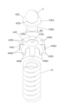
- FIG. 6 is an exploded perspective view of the valve body 3, the valve body support 42A according to the second embodiment, the valve body anti-vibration spring 44, and the coil spring 41.
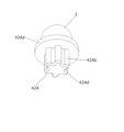
- FIG. 7 is a bottom perspective view of the valve body 3 and the valve body support 42A according to the second embodiment.
- FIG. 8 is a bottom view of the valve body 3 and the valve body support 42A according to the second embodiment. Since the valve body 3, the valve body anti-vibration spring 44, and the coil spring 41 are the same as those in the above-described embodiment, redundant description is omitted.
- the valve body support 42A of this embodiment can be used in the expansion valve 1 of FIG. 1 by fixing the valve body 3 by welding.
- the valve body support 42A has a disc-shaped flange 42Aa and an insertion part 42Ab having a columnar six-petal-like cross-section connected to the lower surface of the flange 42Aa.
- a chamfer 42Ad is formed over the entire circumference at the lower end of the insertion portion 42Ab.
- a concave portion 42Ac is formed in the center of the upper surface of the flange portion 42Aa protruding in the direction orthogonal to the axis line with respect to the insertion portion 42Ab, and the valve body 3 is fitted and welded to the concave portion 42Ac.
- the axis of the valve body support 42A coincides with the axis L of the expansion valve 1 in the assembled state.
- the valve body support 42A can be formed by press molding, forging, or the like.
- the insertion portion 42Ab has a uniform non-circular cross-section in the direction perpendicular to the axis, except for the chamfer 42Ad. As shown in FIG. Located on circle C1. For this reason, when the insertion portion 42Ab is inserted into the mounting hole 44c of the valve body vibration isolating spring 44, the mounting hole 44c and the insertion portion 42Ab are fixed in the direction perpendicular to the axis without looseness, and the insertion portion is cylindrical. , the insertion portion 42Ab uses less material for the portion between its outer periphery and the minimum circumscribed circle C1, thereby achieving weight reduction and material reduction.
- the diameter ⁇ a of the minimum circumscribed circle C1 is equal to the inner diameter ⁇ c of the coil spring 41, by inserting the insertion portion 42Ab into the coil spring 41, fixation without backlash in the direction perpendicular to the axis can be achieved.
- FIG. 9 is an exploded perspective view showing the valve body 3, the valve body support 42D according to the third embodiment, the valve body anti-vibration spring 44, and the coil spring 41.
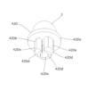
- FIG. 10 is a bottom perspective view of the valve body 3 and the valve body support 42D according to the third embodiment.
- FIG. 11 is a bottom view of the valve body 3 and the valve body support 42D according to the third embodiment. Since the valve body 3, the valve body anti-vibration spring 44, and the coil spring 41 are the same as those in the above-described embodiment, redundant description is omitted.
- the valve body support 42D of this embodiment can be used in the expansion valve 1 of FIG. 1 by fixing the valve body 3 by welding.
- the valve body support 42D has a disk-shaped collar portion 42Da and an inserting portion 42Db connected to the lower surface of the collar portion 42Da.
- the insertion portion 42Db is implanted in the lower surface of the collar portion 42Da and extends parallel to the axis, and is composed of three leg portions 42De that are spaced apart in the circumferential direction.
- the cross-sectional shape is non-circular.
- a chamfer (partial conical surface) 42Dd is formed on the outer peripheral side of the lower end of each leg 42De.
- a concave portion 42Dc is formed in the center of the upper surface of the flange portion 42Da protruding in the direction orthogonal to the axis line with respect to the insertion portion 42Db, and the valve body 3 is fitted and welded to the concave portion 42Dc.
- the axis of the valve body support 42D coincides with the axis L of the expansion valve 1 in the assembled state.
- the valve body support 42D can be formed by press molding, forging, or the like.
- the leg portions 42De each have a common shape, and a part of the outer circumference thereof is on the minimum circumscribed circle C1 of diameter ⁇ a centered on the axis of the valve support 42D and surrounding the entire insertion portion 42Db as shown in FIG. To position. For this reason, when the insertion portion 42Db is inserted into the mounting hole 44c of the valve body anti-vibration spring 44, the mounting hole 44c and the insertion portion 42Db are fixed in the direction perpendicular to the axis without play, and the insertion portion is cylindrical. , the material of the insertion portion 42Db is significantly reduced, and weight reduction and material reduction can be achieved.
- the diameter ⁇ a of the minimum circumscribed circle C1 is equal to the inner diameter ⁇ c of the coil spring 41, by inserting the insertion portion 42Db into the coil spring 41, fixation without backlash in the direction perpendicular to the axis can be achieved.
- the leg portion 42De is formed by forming three slits extending radially from the center of the cylindrical insertion portion 42Db at equal intervals. You can also say.
- FIG. 12 is a perspective view showing the valve body 3, the valve body support 42E according to the fourth embodiment, the valve body anti-vibration spring 44E according to the fourth embodiment, and the coil spring 41 in an exploded state.
- FIG. 13 is a top view of the valve body anti-vibration spring 44E. Since the valve body 3 and the coil spring 41 are the same as those in the above-described embodiment, redundant description will be omitted.
- the valve body support 42E and the valve body vibration isolation spring 44E of this embodiment can be used in the expansion valve 1 of FIG.
- the valve body support 42E is the same as the first embodiment except for the shape of the insertion portion 42Eb, so redundant description will be omitted.
- the insertion portion 42Eb has a cylindrical shape with an outer diameter ⁇ d.
- the valve body anti-vibration spring 44E has the same shape as that of the first embodiment except for the mounting hole 44Ec of the base 44Ea (that is, the leg 44Eb and the protuberance 44Ed), so redundant description will be omitted.
- the mounting hole 44Ec has a regular hexagonal shape, the diameter of the maximum inscribed circle C2 is ⁇ e, the outer diameter ⁇ d of the insertion portion 42Eb and the inner diameter ⁇ c of the coil spring 41 ( 5).
- the outer periphery of the insertion portion 42Eb is a regular hexagon in cross section in the direction orthogonal to the axis line. It abuts at six midpoints on each side of the mounting hole 44Ec and also abuts on the inner circumference of the coil spring 41 over the entire circumference.
- the insertion portion 42Eb (that is, the valve body support 42E and the valve body 3) is fixed to the coil spring 41 in the direction perpendicular to the axis while ensuring coaxiality.
- the mounting hole 44Ec has a regular hexagonal shape (non-circular shape) with a uniform shape when viewed in the axial direction, and as shown in FIG. is located on the maximum inscribed circle C2 of . For this reason, when the insertion portion 42Eb is inserted into the mounting hole 44Ec of the valve body anti-vibration spring 44E, the mounting hole 44Ec and the insertion portion 42Eb are fixed in the direction orthogonal to the axis line without backlash, and compared to the case where they are circular, In the mounting hole 44Ec, the material of the portion between the inner circumference and the maximum inscribed and circumscribed circle C2 is reduced, and weight reduction and material reduction can be achieved.
- FIG. 14 is a bottom perspective view of the valve body 3 and the valve body support 42B according to the fifth embodiment.
- FIG. 15 is a bottom view of the valve body 3 and the valve body support 42B according to the fifth embodiment. Since the valve body 3, the valve body anti-vibration spring 44E, and the coil spring 41 are the same as those in the above-described embodiment, redundant description will be omitted. By fixing the valve body 3 by welding, the valve body support 42B of this embodiment can be used in the expansion valve 1 of FIG. 1 together with the valve body anti-vibration spring 44E according to the fourth embodiment.
- the valve body support 42B is formed by connecting a disk-shaped flange 42Ba and an insertion part 42Bb.
- the insertion portion 42Bb includes a small-diameter disk portion (insertion vicinity portion) 42Be connected to the lower surface of the collar portion 42Ba, and a six-petal-shaped cross-section columnar portion (insertion portion) having six vertices connected to the lower end of the small-diameter disk portion 42Be. far) 42Bf. It is preferable that the thickness of the small-diameter disc portion 42Be be thicker than the thickness of the base portion 44Ea of the valve body anti-vibration spring 44E.
- a chamfer 42Bd is formed over the entire circumference at the lower end of the six-petal-shaped cross-sectional columnar portion 42Bf.
- a concave portion (not shown) is formed in the center of the upper surface of the flange portion 42Ba protruding in the direction orthogonal to the axis line with respect to the insertion portion 42Bb, and the valve body 3 is fitted and welded to the concave portion.
- the axis of the valve body support 42B coincides with the axis L of the expansion valve 1 in FIG. 1 in the assembled state.
- the valve body support 42B can be formed by press molding, forging, or the like.
- the six-petal-like cross-section columnar portion 42Bf has a uniform non-circular cross-section in the direction perpendicular to the axis except for the chamfer 42Bd.
- the outer diameter of the small-diameter disk portion 42Be matches the diameter ⁇ a of the minimum circumscribed circle C1 centered on the axis of the six-petal cross-sectional columnar portion 42Bf, and the inner diameter ⁇ d of the mounting hole 44Ec of the valve body anti-vibration spring 44E. and the inner diameter ⁇ c of the coil spring 41.
- the insertion portion 42Bb when the insertion portion 42Bb is fitted into the mounting hole 44Ec and the inner circumference of the coil spring 41, the outer circumference of the small-diameter disc portion 42Be abuts against the inner circumference of the mounting hole 44Ec at six points, and has a six-petal cross section.
- the outer circumference of the columnar portion 42Bf abuts the inner circumference of the coil spring 41 .
- the insertion portion 42Bb (that is, the valve body support 42B and the valve body 3) is fixed to the coil spring 41 in the direction perpendicular to the axis while ensuring coaxiality.
- the six-petal-like cross-sectional columnar portion 42Bf has a uniform non-circular cross section in the direction perpendicular to the axis except for the chamfer 42Bd, and as shown in FIG. It is located on the minimum circumscribed circle C1 of ⁇ a. Therefore, when the insertion portion 42Bb is inserted into the mounting hole 44Ec of the valve body anti-vibration spring 44E, the mounting hole 44Ec and the insertion portion 42Bb are fixed in the direction perpendicular to the axis without play, and the insertion portion is cylindrical. , the six-petal-like cross-section columnar portion 42Bf uses less material in the portion between its outer periphery and the minimum circumscribed circle C1, thereby achieving weight reduction and material reduction.
- FIG. 16 is a side view of the valve body 3 and a valve body support 42C according to a modification.
- the valve body support 42C is formed by connecting a disk-shaped collar portion 42Ca and an insertion portion 42Cb.
- the insertion portion 42Cb has a small-diameter disk portion 42Ce connected to the lower surface of the collar portion 42Ca, and a hexapetal-shaped cross-sectional columnar portion 42Cf having six vertices connected to the lower end of the small-diameter disk portion 42Ce.
- a transition portion TR (illustrated by a dotted line in FIG. 16) having an arcuate cross section may be formed across the intersection of the collar portion 42Ca and the small-diameter disc portion 42Ce. be. If the transition portion TR remains, the outer circumference of the upper end of the small-diameter disk portion 42Ce will be enlarged, so there is a possibility that it will not be possible to accurately fit the inner circumference of the mounting hole 44Ec of the valve body anti-vibration spring 44E.
- the transition portion TR is removed by machining as post-processing.
- the lower surface of the flange portion 42Ca and the peripheral surface of the small-diameter disk portion 42Ce can be made to intersect at a right angle, and the outer diameter of the small-diameter disk portion 42Ce is equal to the valve body anti-vibration spring 44E.
- the removal of the transition portion formed between the flange portion and the insertion portion is similarly applicable to the embodiments described above and the embodiments described later.
- the removal of the transition portion is sufficient for the portion that abuts against the inner periphery of the mounting hole of the valve body anti-vibration spring.
- FIG. 17 is an exploded perspective view showing the valve body 3, the valve body support 42E, the valve body anti-vibration spring 44F according to the sixth embodiment, and the coil spring 41.
- FIG. FIG. 18 is a top view of the valve body anti-vibration spring 44F. Since the valve body 3, the valve body support 42E, and the coil spring 41 are the same as those in the above-described embodiment, redundant description will be omitted.
- the valve body support 42E and the valve body vibration isolation spring 44F of this embodiment can be used in the expansion valve 1 of FIG.
- the valve body anti-vibration spring 44F has the same shape as that of the first embodiment except for the mounting hole 44Fc of the base 44Fa (that is, the leg piece 44Fb and the raised portion 44Fd), so redundant description will be omitted.
- the mounting hole 44Fc has an eight-petal contour shape, the diameter of the maximum inscribed circle C2 is ⁇ e, the outer diameter ⁇ d of the insertion portion 42Eb, and the inner diameter ⁇ c of the coil spring 41. is equal to , by inserting the insertion portion 42Eb into the coil spring 41, fixation without looseness in the direction perpendicular to the axis can be realized.
- the outer circumference of the insertion portion 42Eb has an eight-petal contour shape in the cross section in the direction orthogonal to the axis line. , and contact the inner circumference of the coil spring 41 over the entire circumference.
- the insertion portion 42Eb (that is, the valve body support 42E and the valve body 3) is fixed to the coil spring 41 in the direction perpendicular to the axis while ensuring coaxiality.
- the mounting hole 44Fc has an eight-petal contour shape (non-circular shape) when viewed in the axial direction, and as shown in FIG. is located on the maximum inscribed circle C2 of . For this reason, when the insertion portion 42Eb is inserted into the mounting hole 44Fc of the valve body anti-vibration spring 44F, the mounting hole 44Fc and the insertion portion 42Eb are fixed in the direction perpendicular to the axis line without looseness, and compared to the case where the insertion portion 42Eb is circular. In the mounting hole 44Fc, the material of the portion between the inner circumference and the maximum inscribed and circumscribed circle C2 is reduced, and weight reduction and material reduction can be achieved.
- FIG. 19 is a perspective view showing the valve body 3, the valve body support 42, the valve body anti-vibration spring 44E, and the coil spring 41 in an exploded state. Since the valve body 3, the valve body support 42, the valve body anti-vibration spring 44E, and the coil spring 41 are the same as those in the above-described embodiment, redundant description will be omitted.
- the valve body support 42 and the valve body vibration isolation spring 44E of this embodiment can be used in the expansion valve 1 of FIG.
- the insertion part 42b of the valve body support 42 has a hexagonal columnar shape
- the mounting hole 44Ec of the valve body anti-vibration spring 44E has a hexagonal shape corresponding to the insertion part 42b when viewed in the axial direction.
- the minimum circumscribed circle diameter ⁇ a of the outer periphery of the insertion portion 42b is equal to the inner diameter ⁇ c of the coil spring 41, by inserting the insertion portion 42b into the coil spring 41, fixation without backlash in the direction perpendicular to the axis can be achieved.
- FIG. 20 is a perspective view showing the valve body 3, the valve body support 42A, the valve body anti-vibration spring 44F, and the coil spring 41 in an exploded state. Since the valve body 3, the valve body support 42A, the valve body anti-vibration spring 44F, and the coil spring 41 are the same as those in the above-described embodiment, redundant description will be omitted.
- the valve body support 42A and the valve body vibration isolation spring 44F of this embodiment can be used in the expansion valve 1 of FIG.
- the insertion part 42Ab of the valve body support 42A has a hexapetal-like cross-sectional columnar shape
- the mounting hole 44Fc of the valve body anti-vibration spring 44F has a hexapetal shape corresponding to the insertion part 42Ab when viewed in the axial direction.
- the insertion portion 42Ab is fitted into the mounting hole 44Fc, the outer circumference of the insertion portion 42Ab and the inner circumference of the mounting hole 44Fc are in contact over the entire circumference.
- the material of the insertion part 42Ab is reduced, and even if the material increase of the valve body anti-vibration spring 44F is taken into consideration, the total weight and material can be reduced.
- the minimum circumscribed circle diameter ⁇ a of the outer periphery of the insertion portion 42Ab is equal to the inner diameter ⁇ c of the coil spring 41, by inserting the insertion portion 42Ab into the coil spring 41, fixation without backlash in the direction perpendicular to the axis is realized.
- the outer circumference of the insertion portion and the inner circumference of the mounting hole have the same shape, but the present invention is not limited to this.
- the shape of the inner periphery of the mounting hole 44Gc is a regular hexagon (non-circular shape)
- the outer periphery of the insertion portion 42Gb is an equilateral triangle (a non-circular shape different from that of the mounting hole 44Gc). )
- the three vertices of a regular hexagon can be brought into contact with the vertices of an equilateral triangle.
- Reference Signs List 1 Expansion valve 2 : Valve body 3 : Valve body 4 : Biasing device 5 : Operating rod 6 : Operating rod anti-vibration spring 8 : Power element 20 : Valve seat 21 : First flow path 22 : Second flow path 23 : Return channel 26 : Annular portion 27 : Operating rod insertion hole 41 : Coil springs 42 to 42E : Valve body support 43 : Spring receiving members 44, 44E, 44F : Valve body anti-vibration spring 100 : Refrigerant circulation system 101 : Compressor 102 : Condenser 104: Evaporator VS: Valve chamber
Landscapes
- Engineering & Computer Science (AREA)
- General Engineering & Computer Science (AREA)
- Mechanical Engineering (AREA)
- Physics & Mathematics (AREA)
- Fluid Mechanics (AREA)
- Thermal Sciences (AREA)
- Temperature-Responsive Valves (AREA)
Abstract
例えば従来と共通の材料を用いながらも、さらなる軽量化やコスト低減を図れる膨張弁を提供する。膨張弁は、弁室内に弁座を備えた弁本体と、前記弁座に着座することにより流体の通過を阻止し、前記弁座から離間することにより前記流体の通過を許容する弁体と、挿入部、及び前記挿入部に対して軸線直交方向にはみ出した鍔部を備え、前記弁体に連結された弁体サポートと、前記挿入部が内側に嵌挿されており、前記弁体サポートを介して前記弁体を前記弁座に向かって付勢するコイルばねと、前記鍔部と前記コイルばねとの間に挟持される防振部材と、を有し、前記防振部材は、前記挿入部が貫通する開口を有する基部と、前記基部から延在して前記弁室の内壁に当接する複数の脚片とを備え、前記弁体サポートの軸線に直交する断面において、前記挿入部の外周と前記開口の内周のうち少なくとも一方が非円形であり、前記挿入部の外周と前記開口の内周とは、周方向に沿って3点以上で接している。
Description
本発明は、膨張弁に関する。
従来、例えば自動車に搭載される空調装置等に用いる冷凍サイクルについては、冷媒の通過量を温度に応じて調整する感温機構内蔵型の温度膨張弁が使用されている。このような膨張弁の弁本体は、高圧の冷媒が導入される入口ポートと入口ポートに連通する弁室を有する。
弁室内に配設される球状の弁体は、弁室に開口する弁孔の弁座に対向し配置される。弁体は、弁室内に配置された支持部材に支持され、弁本体に取り付けられた調整ねじと支持部材との間に設置されたコイルばねにより弁座方向へ付勢される。そして、弁体は、パワーエレメントにより弁棒を介して駆動され、弁座との間の絞り通路の開度を制御する。また、弁孔を通った冷媒は、出口ポートから蒸発器側へ送られる。
ここで、膨張弁の入口ポートに送り込まれる高圧冷媒は圧縮機の動作により圧力変動(脈動)が発生する場合があり、これにより弁体が振動し、異音を発生することがある。そこで、弁体の振動を防止する防振ばねが提案されている(例えば、特許文献1参照)。
特許文献1に記載の膨張弁において、球状の弁体は、弁体サポートと呼称される支持部材に溶接され、この弁体サポートとコイルばねとの間に、防振ばねが挟持されるようにして組み付けが行われる。
近年、環境保護の観点から、エンジン搭載車に関しては燃費軽減が要請され、またバッテリーの電力だけで車輪をモーター駆動するBEV(Battery Electric Vehicle)に関しては、1回の充電による航続距離の延長が要請されている。ここで、車重の軽減は、いずれの要請にも応えることができるため、駆動システムに関わらず有効であるとされる。したがって、車両に搭載される空調装置の重量軽減も切望されており、それに使用する膨張弁の軽量化を図ることは、類似製品との差別化を図る点でも有効である。
膨張弁の軽量化を図るため、より軽量な素材への変更が一案である。しかしながら、材料変更に伴うコスト増や耐久性に与える影響などを考慮すると、同じ材料を用いつつ、より軽量化を図ることが望ましいといえ、それにより材料の削減によるコスト低減も期待できる。
そこで本発明は、例えば従来と共通の材料を用いながらも、さらなる軽量化やコスト低減を図れる膨張弁を提供することを目的とする。
上記目的を達成するために、本発明による膨張弁は、
弁室内に弁座を備えた弁本体と、
前記弁座に着座することにより流体の通過を阻止し、前記弁座から離間することにより前記流体の通過を許容する弁体と、
挿入部、及び前記挿入部に対して軸線直交方向にはみ出した鍔部を備え、前記弁体に連結された弁体サポートと、
前記挿入部が内側に嵌挿されており、前記弁体サポートを介して前記弁体を前記弁座に向かって付勢するコイルばねと、
前記鍔部と前記コイルばねとの間に挟持される防振部材と、を有し、
前記防振部材は、前記挿入部が貫通する開口を有する基部と、前記基部から延在して前記弁室の内壁に当接する複数の脚片とを備え、
前記弁体サポートの軸線に直交する断面において、前記挿入部の外周と前記開口の内周のうち少なくとも一方が非円形であり、前記挿入部の外周と前記開口の内周とは、周方向に沿って3点以上で接している、ことを特徴とする。
弁室内に弁座を備えた弁本体と、
前記弁座に着座することにより流体の通過を阻止し、前記弁座から離間することにより前記流体の通過を許容する弁体と、
挿入部、及び前記挿入部に対して軸線直交方向にはみ出した鍔部を備え、前記弁体に連結された弁体サポートと、
前記挿入部が内側に嵌挿されており、前記弁体サポートを介して前記弁体を前記弁座に向かって付勢するコイルばねと、
前記鍔部と前記コイルばねとの間に挟持される防振部材と、を有し、
前記防振部材は、前記挿入部が貫通する開口を有する基部と、前記基部から延在して前記弁室の内壁に当接する複数の脚片とを備え、
前記弁体サポートの軸線に直交する断面において、前記挿入部の外周と前記開口の内周のうち少なくとも一方が非円形であり、前記挿入部の外周と前記開口の内周とは、周方向に沿って3点以上で接している、ことを特徴とする。
本発明により、例えば従来と共通の材料を用いながらも、さらなる軽量化やコスト低減を図れる膨張弁を提供することができる。
以下、図面を参照して、本発明にかかる実施形態について説明する。
(定義)
本明細書において、弁体3から作動棒5に向かう方向を「上方向」と定義し、作動棒5から弁体3に向かう方向を「下方向」と定義する。よって、本明細書では、膨張弁1の姿勢に関わらず、弁体3から作動棒5に向かう方向を「上方向」と呼ぶ。
また、本明細書において、「周方向に沿って3点以上で接する」とは、内周と外周とが点接触する場合には、軸線に直交する面内において接触点が周方向に180度を超える範囲にわたって3点以上で接するため、軸線直交方向に内周と外周とが互いに固定される状態を意味し、また内周と外周とが線接触する場合には、3点以上の多点で接触するものとみなし、さらに軸線に直交する面内において連続または不連続で180度を超える範囲にわたって線接触するため、線接触した部位の接線方向、及び接線直角方向のいずれにも内周と外周とが互いに固定される状態を意味するものとする。
また、「最小外接円径が内径に等しい」、及び「最大内接円径が外径に等しい」とは、両者が完全に等しい場合のほか、実質的に等しい(例えば部品の製造誤差の範囲でのみ異なる)場合も含む。
本明細書において、弁体3から作動棒5に向かう方向を「上方向」と定義し、作動棒5から弁体3に向かう方向を「下方向」と定義する。よって、本明細書では、膨張弁1の姿勢に関わらず、弁体3から作動棒5に向かう方向を「上方向」と呼ぶ。
また、本明細書において、「周方向に沿って3点以上で接する」とは、内周と外周とが点接触する場合には、軸線に直交する面内において接触点が周方向に180度を超える範囲にわたって3点以上で接するため、軸線直交方向に内周と外周とが互いに固定される状態を意味し、また内周と外周とが線接触する場合には、3点以上の多点で接触するものとみなし、さらに軸線に直交する面内において連続または不連続で180度を超える範囲にわたって線接触するため、線接触した部位の接線方向、及び接線直角方向のいずれにも内周と外周とが互いに固定される状態を意味するものとする。
また、「最小外接円径が内径に等しい」、及び「最大内接円径が外径に等しい」とは、両者が完全に等しい場合のほか、実質的に等しい(例えば部品の製造誤差の範囲でのみ異なる)場合も含む。
(第1の実施形態)
図1を参照して、第1の実施形態における膨張弁1の概要について説明する。図1は、本実施形態における膨張弁1を、冷媒循環システム100に適用した例を模式的に示す概略断面図である。本実施形態では、膨張弁1は、コンプレッサ101と、コンデンサ102と、エバポレータ104とに流体接続されている。膨張弁1の軸線をLとする。
図1を参照して、第1の実施形態における膨張弁1の概要について説明する。図1は、本実施形態における膨張弁1を、冷媒循環システム100に適用した例を模式的に示す概略断面図である。本実施形態では、膨張弁1は、コンプレッサ101と、コンデンサ102と、エバポレータ104とに流体接続されている。膨張弁1の軸線をLとする。
膨張弁1は、弁室VSを備える弁本体2と、弁体3と、付勢装置4と、作動棒5と、リングばね6と、パワーエレメント8とを具備する。膨張弁1の軸線をLとする。
弁本体2は、弁室VSに加え、第1流路21、第2流路22及び戻り流路23を備える。第1流路21は供給側流路であり、弁室VSには、供給側流路を介して冷媒(流体ともいう)が供給される。第2流路22は排出側流路であり、弁室VS内の流体は、作動棒挿通孔27及び排出側流路を介して膨張弁外に排出される。第1流路21と弁室VSとの間は、第1流路21より小径の接続路21aにより連通している。
球状の弁体3は、弁室VS内に配置される。弁体3が弁本体2の環状の弁座20に着座しているとき、第1流路21と第2流路22とは非連通状態となる。一方、弁体3が弁座20から離間しているとき、第1流路21と第2流路22とは連通状態となる。
作動棒挿通孔27に隙間を持って挿通された作動棒5の下端は、弁体3の上面に接触している。また、作動棒5は、付勢装置4による付勢力に抗して弁体3を開弁方向に押圧することができる。作動棒5が下方向に移動するとき、弁体3は、弁座20から離間し、膨張弁1が開状態となる。
作動棒5は軸線Lに沿って、弁本体2に同軸に形成された作動棒挿通孔27、中央孔28、環状部26、戻り流路23、連通路2bを介して、弁体3からパワーエレメント8まで延在している。作動棒5を摺動可能に保持する中央孔28の内径に対し、環状部26の内径はより大きくなっている。環状部26には、作動棒5の防振機能を有する作動棒防振ばね6が配置されている。作動棒防振ばね6は、例えば特開2018-25332号公報に詳細が記載されているため、ここでは説明を省略する。
なお、第2流路22、戻り流路23のいずれも、冷凍サイクルにおいては低圧側に位置するが、冷媒がエバポレータ104を通過して圧損を受けるため、前者が相対的に高圧となる。したがって、第2流路22を高圧流路、戻り流路23を低圧流路と称することがある。
次にパワーエレメント8について説明する。パワーエレメント8は、弁本体2の頂部に設けられた凹部2aに取り付けられている。凹部2aは連通路2bを介して、エバポレータ104からの冷媒が通過する、弁本体2内の戻り流路23と連通している。
パワーエレメント8は、栓81と、上蓋部材82と、ダイアフラム83と、ストッパ部材84と、受け部材86とを有する。
上蓋部材82の頂部には穴82aが形成され、栓81により封止可能となっている。
ダイアフラム83は、同心円の凹凸形状を複数個形成した薄い板材からなる。
ストッパ部材84は、円盤部と、該円盤部の下面に同軸に連設された円筒部とを有し、円筒部の下端中央には嵌合孔84cが形成されている。
受け部材86は、上蓋部材82の外径とほぼ同じ外径を持つフランジ部と、該フランジ部の下端に連設された中空円筒部とを有し、中空円筒部の外周には雄ねじ86cが形成されている。
パワーエレメント8の組立時に、まず上蓋部材82と、ダイアフラム83と、受け部材86のフランジ部のそれぞれ外周部を重ね合わせた状態で、当該外周部を例えばTIG溶接やレーザ溶接、プラズマ溶接等により周溶接して一体化する。
続いて、上蓋部材82に形成された穴82aから、上蓋部材82とダイアフラム83とで囲われる空間(圧力作動室PAという)内に作動ガスを封入した後、穴82aを栓81で封止し、更に例えばプロジェクション溶接を用いて、栓81を上蓋部材82に固定する。
このとき、圧力作動室PAに封入された作動ガスにより、ダイアフラム83は受け部材86側に張り出す形で圧力を受けるため、ダイアフラム83と受け部材86とで囲われる下部空間LSに配置されたストッパ部材84の上面と当接して支持される。なお、ストッパ部材84の円盤部が受け部材86により保持されるので、ストッパ部材84はパワーエレメント8から抜け出ることはない。
パワーエレメント8を弁本体2に組み付けるときは、作動棒5の上端をストッパ部材84の嵌合孔84cに嵌合させた状態で、弁本体2に組み付けた作動棒防振ばね6を通過させつつ、作動棒5を弁本体2内に挿入する。さらに、受け部材86の雄ねじ86cを弁本体2の凹部2aの雌ねじに螺合させ、ねじ込むことによりパワーエレメント8を弁本体2に固定する。かかる状態で、パワーエレメント8の下部空間LSは戻り流路23と連通し、すなわち同じ内圧となる。
次に、付勢装置4について説明する。図1において、付勢装置4は、円形の線材を螺旋状に巻いたコイルばね41と、コイルばね41の上端に取り付けられて弁体3を支持する弁体サポート42と、コイルばね41の下端を支持しつつ弁本体2に取り付けるばね受け部材43と、弁体防振ばね(防振部材)44とを有する。ばね受け部材43は弁本体2の弁室VSを密閉するとともに、弁体3を弁座20に向かって付勢するコイルばね41の端部を支持する機能を有する。
弁体サポート42の上面には球状の弁体3が溶接され、両者は一体となっている。
図2は、弁体3及び弁体サポート42と、弁体防振ばね44と、コイルばね41とを分解した状態で示す斜視図である。図3は、弁体3及び弁体サポート42を下方から見た斜視図である。図4は、弁体3及び弁体サポート42を下面視した図である。図5は、コイルばね41を上面視した図である。
弁体サポート42は、円板状の鍔部42aと、鍔部42aの下面に連設された略六角柱状の挿入部42bとを有する。挿入部42bの下端には、全周にわたって面取り42dが形成されている。挿入部42bに対して軸線直交方向にはみ出した(すなわち挿入部42bの最小外接円より大径の)鍔部42aの上面中央には凹部42cが形成され、凹部42cに弁体3が嵌合して溶接されている。弁体サポート42の軸線は、組付状態で膨張弁1の軸線Lに一致する。弁体サポート42は、プレス成形や鍛造等により形成できる。
挿入部42bは、軸線直交方向の断面が面取り42dを除いて一様な六角柱形状(非円形状)であり、図4に示すように、該断面における六角形の頂点は、軸線を中心とする径φaの最小外接円C1上に位置する。このため、挿入部が円筒状である場合と比較すると、挿入部42bは、その外周と、最小外接円C1との間の部位の材料が削減されることとなり、軽量化と材料削減とを図れる。
図2において、弁体防振ばね44は、基部44aと、脚片44bとを連設してなり、ステンレス鋼、その合金等、弾性のある板材にプレス加工を施すことによって成形される。
基部44aは、弁体防振ばね44の上部を形成する略円環状の部位であり、中央に円形の取付孔(開口ともいう)44cを有する。取付孔44cの内径φbは、コイルばね41の内径φc(図5参照)と等しい。取付孔44c内に弁体サポート42の挿入部42bを挿通した状態で、基部44aが弁体サポート42の鍔部42aの下面とコイルばね41の上端とに挟持されるようにして取り付けられる。
本実施形態において、挿入部42bの最小外接円C1の径φaが、取付孔44cの内径φb、及びコイルばね41の内径φcと等しいため、挿入部42bの外周は、軸線直交方向断面において、面取り42dを除き、六角形の頂点に対応する6か所にて取付孔44cの内周、及びコイルばね41の内周に当接する。これにより、軸線直交方向において、コイルばね41に対して挿入部42b(すなわち弁体サポート42及び弁体3)は、同軸性が確保されつつ固定された状態となる。なお、取付孔44cの内周において、挿入部42bの外周に当接しない部位にスリットや切欠を設けることは任意であり、後述する実施形態においても同様である。
脚片44bは、基部44aの外周側から放射状に複数本延びており、ここでは同じ長さの8本の脚片44bが周方向に等角度間隔で備えられている。各脚片44bは、基部44aに対し直角未満の角度で略L字状に折り曲げられており、先端近傍に外側に向いて半球状に突出した隆起部44dを有する。
隆起部44dは、付勢装置4が弁室VSに設置されたときに、弁室VSの上部内壁に弾発的に接触するが、弁体3が最下限位置となった場合でも弁本体2の接続路21aに入り込まないように設定されている。
(膨張弁の動作)
図1を参照して、膨張弁1の動作例について説明する。コンプレッサ101で加圧された冷媒は、コンデンサ102で液化され、膨張弁1に送られる。また、膨張弁1で断熱膨張された冷媒はエバポレータ104に送り出され、エバポレータ104で、エバポレータの周囲を流れる空気と熱交換される。エバポレータ104から戻る冷媒は、膨張弁1(より具体的には、戻り流路23)を通ってコンプレッサ101側へ戻される。このとき、エバポレータ104を通過することで、第2流路22内の流体圧は、戻り流路23の流体圧より大きくなる。
図1を参照して、膨張弁1の動作例について説明する。コンプレッサ101で加圧された冷媒は、コンデンサ102で液化され、膨張弁1に送られる。また、膨張弁1で断熱膨張された冷媒はエバポレータ104に送り出され、エバポレータ104で、エバポレータの周囲を流れる空気と熱交換される。エバポレータ104から戻る冷媒は、膨張弁1(より具体的には、戻り流路23)を通ってコンプレッサ101側へ戻される。このとき、エバポレータ104を通過することで、第2流路22内の流体圧は、戻り流路23の流体圧より大きくなる。
膨張弁1には、コンデンサ102から高圧冷媒が供給される。より具体的には、コンデンサ102からの高圧冷媒は、第1流路21を介して弁室VSに供給される。
弁体3が、弁座20に着座しているとき(換言すれば、膨張弁1が閉状態のとき)には、弁室VSの上流側の第1流路21と弁室VSの下流側の第2流路22とは、非連通状態である。他方、弁体3が、弁座20から離間しているとき(換言すれば、膨張弁1が開状態のとき)には、弁室VSに供給された冷媒は、作動棒挿通孔27及び第2流路22を通って、エバポレータ104へ送り出される。なお、膨張弁1の閉状態と開状態との間の切り換えは、パワーエレメント8に接続された作動棒5によって行われる。
図1において、パワーエレメント8の内部には、ダイアフラム83により仕切られた圧力作動室PAと下部空間LSとが設けられている。このため、圧力作動室PA内の作動ガスが液化されると、作動棒5は上方向に移動し、液化された作動ガスが気化すると、作動棒5は下方向に移動する。こうして、膨張弁1の開状態と閉状態との間の切り換えが行われる。
更に、パワーエレメント8の下部空間LSは、戻り流路23と連通している。このため、戻り流路23を流れる冷媒の温度、圧力に応じて、圧力作動室PA内の作動ガスの相(気相、液相等)が変化し、作動棒5が駆動される。換言すれば、図1に記載の膨張弁1では、エバポレータ104から膨張弁1に戻る冷媒の温度、圧力に応じて、膨張弁1からエバポレータ104に向けて供給される冷媒の量が自動的に調整される。
本実施の形態によれば、弁体サポート42の軽量化が図られているため、弁体3及び弁体サポートの合計質量が低減して固有振動数が高くなり、それにより膨張弁1の動作時における共振などを抑制することができる。
(第2の実施形態)
図6は、弁体3及び第2の実施形態にかかる弁体サポート42Aと、弁体防振ばね44と、コイルばね41とを分解した状態で示す斜視図である。図7は、弁体3及び第2の実施形態にかかる弁体サポート42Aを下方から見た斜視図である。図8は、弁体3及び第2の実施形態にかかる弁体サポート42Aを下面視した図である。弁体3、弁体防振ばね44、及びコイルばね41は、上述した実施形態と同様であるため、重複説明を省略する。本実施形態の弁体サポート42Aは、弁体3を溶接固定することにより、図1の膨張弁1に使用できる。
図6は、弁体3及び第2の実施形態にかかる弁体サポート42Aと、弁体防振ばね44と、コイルばね41とを分解した状態で示す斜視図である。図7は、弁体3及び第2の実施形態にかかる弁体サポート42Aを下方から見た斜視図である。図8は、弁体3及び第2の実施形態にかかる弁体サポート42Aを下面視した図である。弁体3、弁体防振ばね44、及びコイルばね41は、上述した実施形態と同様であるため、重複説明を省略する。本実施形態の弁体サポート42Aは、弁体3を溶接固定することにより、図1の膨張弁1に使用できる。
弁体サポート42Aは、円板状の鍔部42Aaと、鍔部42Aaの下面に連設された六花弁様断面柱状の挿入部42Abとを有する。挿入部42Abの下端には、全周にわたって面取り42Adが形成されている。挿入部42Abに対して軸線直交方向にはみ出した鍔部42Aaの上面中央には凹部42Acが形成され、凹部42Acに弁体3が嵌合して溶接されている。弁体サポート42Aの軸線は、組付状態で膨張弁1の軸線Lに一致する。弁体サポート42Aは、プレス成形や鍛造等により形成できる。
挿入部42Abは、軸線直交方向の断面が面取り42Adを除いて一様な非円形状であり、図8に示すように、該断面における六つの頂点は、軸線を中心とする径φaの最小外接円C1上に位置する。このため、弁体防振ばね44の取付孔44cに挿入部42Abを挿通したときに、取付孔44cと挿入部42Abとが軸線直交方向にガタなく固定され、また挿入部が円筒状である場合と比較すると、挿入部42Abは、その外周と、最小外接円C1との間の部位の材料が削減されることとなり、軽量化と材料削減とを図れる。最小外接円C1の径φaは、コイルばね41の内径φcに等しいため、挿入部42Abをコイルばね41に挿入することで、軸線直交方向にガタのない固定が実現する。
(第3の実施形態)
図9は、弁体3及び第3の実施形態にかかる弁体サポート42Dと、弁体防振ばね44と、コイルばね41とを分解した状態で示す斜視図である。図10は、弁体3及び第3の実施形態にかかる弁体サポート42Dを下方から見た斜視図である。図11は、弁体3及び第3の実施形態にかかる弁体サポート42Dを下面視した図である。弁体3、弁体防振ばね44、及びコイルばね41は、上述した実施形態と同様であるため、重複説明を省略する。本実施形態の弁体サポート42Dは、弁体3を溶接固定することにより、図1の膨張弁1に使用できる。
図9は、弁体3及び第3の実施形態にかかる弁体サポート42Dと、弁体防振ばね44と、コイルばね41とを分解した状態で示す斜視図である。図10は、弁体3及び第3の実施形態にかかる弁体サポート42Dを下方から見た斜視図である。図11は、弁体3及び第3の実施形態にかかる弁体サポート42Dを下面視した図である。弁体3、弁体防振ばね44、及びコイルばね41は、上述した実施形態と同様であるため、重複説明を省略する。本実施形態の弁体サポート42Dは、弁体3を溶接固定することにより、図1の膨張弁1に使用できる。
弁体サポート42Dは、円板状の鍔部42Daと、鍔部42Daの下面に連設された挿入部42Dbとを有する。挿入部42Dbは、鍔部42Daの下面に植設され軸線に沿って平行に延在し、周方向に離間して配置される3つの脚部42Deからなり、そのため軸線直交方向における挿入部42Dbの断面形状は非円形状である。脚部42Deの下端外周側には、それぞれ面取り(部分円錐面)42Ddが形成されている。
挿入部42Dbに対して軸線直交方向にはみ出した鍔部42Daの上面中央には凹部42Dcが形成され、凹部42Dcに弁体3が嵌合して溶接されている。弁体サポート42Dの軸線は、組付状態で膨張弁1の軸線Lに一致する。弁体サポート42Dは、プレス成形や鍛造等により形成できる。
脚部42Deは、それぞれ共通の形状を有し、その外周の一部は、図11に示すように弁体サポート42Dの軸線を中心とし挿入部42Db全体を囲む径φaの最小外接円C1上に位置する。このため、弁体防振ばね44の取付孔44cに挿入部42Dbを挿通したときに、取付孔44cと挿入部42Dbとが軸線直交方向にガタなく固定され、また挿入部が円筒状である場合と比較すると、挿入部42Dbは、材料が大幅に削減されることとなり、軽量化と材料削減とを図れる。最小外接円C1の径φaは、コイルばね41の内径φcに等しいため、挿入部42Dbをコイルばね41に挿入することで、軸線直交方向にガタのない固定が実現する。
なお、本実施形態の弁体サポート42Dは、視点を変えると、円筒状の挿入部42Dbの中心から径方向に延在する3つのスリットを等間隔で形成することにより、脚部42Deを形成したということもできる。
(第4の実施形態)
図12は、弁体3及び第4の実施形態にかかる弁体サポート42Eと、第4の実施形態にかかる弁体防振ばね44Eと、コイルばね41とを分解した状態で示す斜視図である。図13は、弁体防振ばね44Eを上面視した図である。弁体3及びコイルばね41は、上述した実施形態と同様であるため、重複説明を省略する。本実施形態の弁体サポート42E及び弁体防振ばね44Eは、図1の膨張弁1に使用できる。
図12は、弁体3及び第4の実施形態にかかる弁体サポート42Eと、第4の実施形態にかかる弁体防振ばね44Eと、コイルばね41とを分解した状態で示す斜視図である。図13は、弁体防振ばね44Eを上面視した図である。弁体3及びコイルばね41は、上述した実施形態と同様であるため、重複説明を省略する。本実施形態の弁体サポート42E及び弁体防振ばね44Eは、図1の膨張弁1に使用できる。
弁体サポート42Eは、挿入部42Eb以外の形状は、第1の実施形態と同様であるため、重複説明を省略する。挿入部42Ebは、外径φdを有する円筒形状である。
弁体防振ばね44Eは、基部44Eaの取付孔44Ec以外(すなわち脚片44Eb,隆起部44Ed)の形状は、第1の実施形態と同様であるため、重複説明を省略する。図13に示すように、取付孔44Ecは正六角形状を有しており、その最大内接円C2の径はφeであって、挿入部42Ebの外径φd、及びコイルばね41の内径φc(図5参照)に等しい。
挿入部42Ebの外径φdが、取付孔44Ecの最大内接円C2の径φe、及びコイルばね41の内径φcと等しいため、挿入部42Ebの外周は、軸線直交方向断面において、正六角形である取付孔44Ecの各辺中点の6か所にて当接し、またコイルばね41の内周に全周にわたって当接する。これにより、軸線直交方向において、コイルばね41に対して挿入部42Eb(すなわち弁体サポート42E及び弁体3)は、同軸性が確保されつつ固定された状態となる。
取付孔44Ecは、軸線方向に見た形状が一様な正六角形状(非円形状)であり、図16に示すように、取付孔44Ecの各辺中点は、軸線を中心とする径φeの最大内接円C2上に位置する。このため、弁体防振ばね44Eの取付孔44Ecに挿入部42Ebを挿通したときに、取付孔44Ecと挿入部42Ebとが軸線直交方向にガタなく固定され、また円形である場合と比較すると、取付孔44Ecは、その内周と、最大内外接円C2との間の部位の材料が削減されることとなり、軽量化と材料削減とを図れる。
(第5の実施形態)
図14は、弁体3及び第5の実施形態にかかる弁体サポート42Bを下方から見た斜視図である。図15は、弁体3及び第5の実施形態にかかる弁体サポート42Bを下面視した図である。弁体3、弁体防振ばね44E、及びコイルばね41は、上述した実施形態と同様であるため、重複説明を省略する。本実施形態の弁体サポート42Bは、弁体3を溶接固定することにより、第4の実施形態にかかる弁体防振ばね44Eと共に、図1の膨張弁1に使用できる。
図14は、弁体3及び第5の実施形態にかかる弁体サポート42Bを下方から見た斜視図である。図15は、弁体3及び第5の実施形態にかかる弁体サポート42Bを下面視した図である。弁体3、弁体防振ばね44E、及びコイルばね41は、上述した実施形態と同様であるため、重複説明を省略する。本実施形態の弁体サポート42Bは、弁体3を溶接固定することにより、第4の実施形態にかかる弁体防振ばね44Eと共に、図1の膨張弁1に使用できる。
弁体サポート42Bは、円板状の鍔部42Baと、挿入部42Bbとを連設してなる。挿入部42Bbは、鍔部42Baの下面に連設された小径円盤部(挿入近部)42Beと、小径円盤部42Beの下端に連設された6つの頂点を有する六花弁様断面柱状部(挿入遠部)42Bfとを有する。小径円盤部42Beの厚みは、弁体防振ばね44Eの基部44Eaの厚みよりも厚いと好ましい。
六花弁様断面柱状部42Bfの下端には、全周にわたって面取り42Bdが形成されている。挿入部42Bbに対して軸線直交方向にはみ出した鍔部42Baの上面中央には凹部(不図示)が形成され、凹部に弁体3が嵌合して溶接されている。弁体サポート42Bの軸線は、組付状態で図1の膨張弁1の軸線Lに一致する。弁体サポート42Bは、プレス成形や鍛造等により形成できる。
六花弁様断面柱状部42Bfは、軸線直交方向の断面が面取り42Bdを除いて一様な非円形状である。一方、小径円盤部42Beの外径は、六花弁様断面柱状部42Bfの軸線を中心とする最小外接円C1の径φaに一致するとともに、弁体防振ばね44Eの取付孔44Ecの内径φd、及びコイルばね41の内径φcとも等しい。したがって、挿入部42Bbを取付孔44Ec及びコイルばね41の内周に嵌合させたとき、小径円盤部42Beの外周が、取付孔44Ecの内周に対して六ケ所で当接し、また六花弁様断面柱状部42Bfの外周がコイルばね41の内周に当接する。これにより、軸線直交方向において、コイルばね41に対して挿入部42Bb(すなわち弁体サポート42B及び弁体3)は、同軸性が確保されつつ固定された状態となる。
六花弁様断面柱状部42Bfは、軸線直交方向の断面が面取り42Bdを除いて一様な非円形状であり、図15に示すように、該断面における六つの頂点は、軸線を中心とする径φaの最小外接円C1上に位置する。このため、弁体防振ばね44Eの取付孔44Ecに挿入部42Bbを挿通したときに、取付孔44Ecと挿入部42Bbとが軸線直交方向にガタなく固定され、また挿入部が円筒状である場合と比較すると、六花弁様断面柱状部42Bfは、その外周と、最小外接円C1との間の部位の材料が削減されることとなり、軽量化と材料削減とを図れる。
(変形例)
図16は、弁体3及び変形例にかかる弁体サポート42Cを側面視した図である。弁体サポート42Cは、第5の実施形態と同様に、円板状の鍔部42Caと、挿入部42Cbとを連設してなる。挿入部42Cbは、鍔部42Caの下面に連設された小径円盤部42Ceと、小径円盤部42Ceの下端に連設された6つの頂点を有する六花弁様断面柱状部42Cfとを有する。
図16は、弁体3及び変形例にかかる弁体サポート42Cを側面視した図である。弁体サポート42Cは、第5の実施形態と同様に、円板状の鍔部42Caと、挿入部42Cbとを連設してなる。挿入部42Cbは、鍔部42Caの下面に連設された小径円盤部42Ceと、小径円盤部42Ceの下端に連設された6つの頂点を有する六花弁様断面柱状部42Cfとを有する。
弁体サポート42Cをプレス成形または鍛造等で形成すると、鍔部42Caと小径円盤部42Ceの交差部に跨って、断面円弧状の遷移部TR(図16に点線で図示)が形成されることがある。遷移部TRが残存すると、小径円盤部42Ceの上端外周が拡径してしまうため、弁体防振ばね44Eの取付孔44Ecの内周に対して精度よく嵌合できない恐れがある。
そこで、本変形例においては、プレス成形または鍛造等で弁体サポート42Cを形成した後、後加工として機械加工により遷移部TRを除去する。これにより図16に実線で図示するように、鍔部42Caの下面と小径円盤部42Ceの周面とを直角に交差させることができ、小径円盤部42Ceの外径が、弁体防振ばね44Eの取付孔44Ecの最大内接円と一致することで、両者を精度よく嵌合させることができる。
なお、鍔部と挿入部との間に形成される遷移部の除去については、上述した実施形態及び後述する実施形態にも同様に適用可能である。特に、非円形状の挿入部の場合、遷移部の除去は、弁体防振ばねの取付孔の内周に当接する部位だけで足りるため、加工工数が大幅に増大することはない。
(第6の実施形態)
図17は、弁体3及び弁体サポート42Eと、第6の実施形態にかかる弁体防振ばね44Fと、コイルばね41とを分解した状態で示す斜視図である。図18は、弁体防振ばね44Fを上面視した図である。弁体3、弁体サポート42E、及びコイルばね41は、上述した実施形態と同様であるため、重複説明を省略する。本実施形態の弁体サポート42E及び弁体防振ばね44Fは、図1の膨張弁1に使用できる。
図17は、弁体3及び弁体サポート42Eと、第6の実施形態にかかる弁体防振ばね44Fと、コイルばね41とを分解した状態で示す斜視図である。図18は、弁体防振ばね44Fを上面視した図である。弁体3、弁体サポート42E、及びコイルばね41は、上述した実施形態と同様であるため、重複説明を省略する。本実施形態の弁体サポート42E及び弁体防振ばね44Fは、図1の膨張弁1に使用できる。
弁体防振ばね44Fは、基部44Faの取付孔44Fc以外(すなわち脚片44Fb,隆起部44Fd)の形状は、第1の実施形態と同様であるため、重複説明を省略する。図18に示すように、取付孔44Fcは八花弁輪郭形状を有しており、その最大内接円C2の径はφeであって、挿入部42Ebの外径φd、及びコイルばね41の内径φcに等しいため、挿入部42Ebをコイルばね41に挿入することで、軸線直交方向にガタのない固定が実現する。
挿入部42Ebの外径φdが、取付孔44Fcの最大内接円C2の径φe、及びコイルばね41の内径φcと等しいため、挿入部42Ebの外周は、軸線直交方向断面において、八花弁輪郭形である取付孔44Fcの中心に最も近づいた点8か所にて当接し、またコイルばね41の内周に全周にわたって当接する。これにより、軸線直交方向において、コイルばね41に対して挿入部42Eb(すなわち弁体サポート42E及び弁体3)は、同軸性が確保されつつ固定された状態となる。
取付孔44Fcは、軸線方向に見た形状が八花弁輪郭形状(非円形状)であり、図18に示すように、挿入部42Ebに対する取付孔44Fcの当接点は、軸線を中心とする径φeの最大内接円C2上に位置する。このため、弁体防振ばね44Fの取付孔44Fcに挿入部42Ebを挿通したときに、取付孔44Fcと挿入部42Ebとが軸線直交方向にガタなく固定され、また円形である場合と比較すると、取付孔44Fcは、その内周と、最大内外接円C2との間の部位の材料が削減されることとなり、軽量化と材料削減とを図れる。
(第7の実施形態)
図19は、弁体3及び弁体サポート42と、弁体防振ばね44Eと、コイルばね41とを分解した状態で示す斜視図である。弁体3、弁体サポート42、弁体防振ばね44E、及びコイルばね41は、上述した実施形態と同様であるため、重複説明を省略する。本実施形態の弁体サポート42及び弁体防振ばね44Eは、図1の膨張弁1に使用できる。
図19は、弁体3及び弁体サポート42と、弁体防振ばね44Eと、コイルばね41とを分解した状態で示す斜視図である。弁体3、弁体サポート42、弁体防振ばね44E、及びコイルばね41は、上述した実施形態と同様であるため、重複説明を省略する。本実施形態の弁体サポート42及び弁体防振ばね44Eは、図1の膨張弁1に使用できる。
弁体サポート42の挿入部42bは、六角柱状であり、また弁体防振ばね44Eの取付孔44Ecは、軸線方向に見て、挿入部42bに対応する六角形である。挿入部42bを取付孔44Ecに嵌合させたとき、挿入部42bの外周と取付孔44Ecの内周とは、全周にわたって当接する。挿入部が円筒状である場合と比較すると、挿入部42bは材料が削減されることとなり、弁体防振ばね44Eの材料増分を考慮しても、トータルで軽量化と材料削減とを図れる。挿入部42bの外周の最小外接円径φaは、コイルばね41の内径φcに等しいため、挿入部42bをコイルばね41に挿入することで、軸線直交方向にガタのない固定が実現する。
(第8の実施形態)
図20は、弁体3及び弁体サポート42Aと、弁体防振ばね44Fと、コイルばね41とを分解した状態で示す斜視図である。弁体3、弁体サポート42A、弁体防振ばね44F、及びコイルばね41は、上述した実施形態と同様であるため、重複説明を省略する。本実施形態の弁体サポート42A及び弁体防振ばね44Fは、図1の膨張弁1に使用できる。
図20は、弁体3及び弁体サポート42Aと、弁体防振ばね44Fと、コイルばね41とを分解した状態で示す斜視図である。弁体3、弁体サポート42A、弁体防振ばね44F、及びコイルばね41は、上述した実施形態と同様であるため、重複説明を省略する。本実施形態の弁体サポート42A及び弁体防振ばね44Fは、図1の膨張弁1に使用できる。
弁体サポート42Aの挿入部42Abは、六花弁様断面柱状であり、また弁体防振ばね44Fの取付孔44Fcは、軸線方向に見て、挿入部42Abに対応した六花弁形である。挿入部42Abを取付孔44Fcに嵌合させたとき、挿入部42Abの外周と取付孔44Fcの内周とは、全周にわたって当接する。挿入部が円筒状である場合と比較すると、挿入部42Abは材料が削減されることとなり、弁体防振ばね44Fの材料増分を考慮しても、トータルで軽量化と材料削減とを図れる。挿入部42Abの外周の最小外接円径φaは、コイルばね41の内径φcに等しいため、挿入部42Abをコイルばね41に挿入することで、軸線直交方向にガタのない固定が実現する。
(変形例)
第7及び第8の実施形態では、挿入部の外周と取付孔の内周の形状を一致させているが、それに限られない。例えば図21に示すように、軸線方向に見て、取付孔44Gcの内周の形状を正六角形(非円形状)とし、挿入部42Gbの外周を正三角形(取付孔44Gcとは異なる非円形状)として、正六角形の3つの頂点に正三角形の頂点をそれぞれ当接させることもできる。
第7及び第8の実施形態では、挿入部の外周と取付孔の内周の形状を一致させているが、それに限られない。例えば図21に示すように、軸線方向に見て、取付孔44Gcの内周の形状を正六角形(非円形状)とし、挿入部42Gbの外周を正三角形(取付孔44Gcとは異なる非円形状)として、正六角形の3つの頂点に正三角形の頂点をそれぞれ当接させることもできる。
なお、本発明は、上述の実施形態に限定されない。本発明の範囲内において、上述の実施形態の任意の構成要素の変形が可能である。また、上述の実施形態において任意の構成要素の追加または省略が可能である。
1 :膨張弁
2 :弁本体
3 :弁体
4 :付勢装置
5 :作動棒
6 :作動棒防振ばね
8 :パワーエレメント
20 :弁座
21 :第1流路
22 :第2流路
23 :戻り流路
26 :環状部
27 :作動棒挿通孔
41 :コイルばね
42~42E :弁体サポート
43 :ばね受け部材
44、44E、44F :弁体防振ばね
100 :冷媒循環システム
101 :コンプレッサ
102 :コンデンサ
104 :エバポレータ
VS :弁室
2 :弁本体
3 :弁体
4 :付勢装置
5 :作動棒
6 :作動棒防振ばね
8 :パワーエレメント
20 :弁座
21 :第1流路
22 :第2流路
23 :戻り流路
26 :環状部
27 :作動棒挿通孔
41 :コイルばね
42~42E :弁体サポート
43 :ばね受け部材
44、44E、44F :弁体防振ばね
100 :冷媒循環システム
101 :コンプレッサ
102 :コンデンサ
104 :エバポレータ
VS :弁室
Claims (14)
- 弁室内に弁座を備えた弁本体と、
前記弁座に着座することにより流体の通過を阻止し、前記弁座から離間することにより前記流体の通過を許容する弁体と、
挿入部、及び前記挿入部に対して軸線直交方向にはみ出した鍔部を備え、前記弁体に連結された弁体サポートと、
前記挿入部が内側に嵌挿されており、前記弁体サポートを介して前記弁体を前記弁座に向かって付勢するコイルばねと、
前記鍔部と前記コイルばねとの間に挟持される防振部材と、を有し、
前記防振部材は、前記挿入部が貫通する開口を有する基部と、前記基部から延在して前記弁室の内壁に当接する複数の脚片とを備え、
前記弁体サポートの軸線に直交する断面において、前記挿入部の外周と前記開口の内周のうち少なくとも一方が非円形であり、前記挿入部の外周と前記開口の内周とは、周方向に沿って3点以上で接している、
ことを特徴とする膨張弁。 - 前記弁体サポートの軸線に直交する断面において、前記挿入部の外周が非円形であり、前記開口の内周が円形である、
ことを特徴とする請求項1に記載の膨張弁。 - 前記弁体サポートの軸線に直交する断面において、前記挿入部の外周の最小外接円径は、前記開口の内径に等しい、
ことを特徴とする請求項2に記載の膨張弁。 - 前記弁体サポートの軸線に直交する断面において、前記挿入部の外周の最小外接円径は、前記コイルばねの内径に等しい、
ことを特徴とする請求項2または3に記載の膨張弁。 - 前記弁体サポートの軸線に直交する断面において、前記挿入部の外周が円形であり、前記開口の内周が非円形である、
ことを特徴とする請求項1に記載の膨張弁。 - 前記弁体サポートの軸線に直交する断面において、前記開口の内周の最大内接円径は、前記挿入部の外径に等しい、
ことを特徴とする請求項5に記載の膨張弁。 - 前記弁体サポートの軸線に直交する断面において、前記挿入部の外径は、前記コイルばねの内径に等しい、
ことを特徴とする請求項5または6に記載の膨張弁。 - 前記挿入部は、挿入近部と、前記挿入近部よりも前記鍔部側から遠い側に位置する挿入遠部とを有し、
前記弁体サポートの軸線に直交する断面において、前記挿入近部の外周が円形であり、前記防振部材の前記開口の内周が非円形であって、前記挿入近部の外周と前記開口の内周とが接する、ことを特徴とする請求項1に記載の膨張弁。 - 前記弁体サポートの軸線に直交する断面において、前記挿入遠部は非円形状を有し、前記挿入遠部の最小外接円径は、前記コイルばねの内径に等しい、
ことを特徴とする請求項8に記載の膨張弁。 - 前記挿入部は、前記弁体サポートの軸線に沿って延在し、周方向に離間して配置される複数の脚部を有する、
ことを特徴とする請求項2に記載の膨張弁。 - 前記弁体サポートの軸線に直交する断面において、複数の前記脚部を囲む最小外接円径は、前記開口の内径に等しい、
ことを特徴とする請求項10に記載の膨張弁。 - 前記弁体サポートの軸線に直交する断面において、複数の前記脚部を囲む最小外接円径は、前記コイルばねの内径に等しい、
ことを特徴とする請求項10または11に記載の膨張弁。 - 前記弁体サポートの軸線に直交する断面において、前記挿入部の外周が非円形であり、前記開口の内周が、前記挿入部の外周に対応した非円形である、
ことを特徴とする請求項1に記載の膨張弁。 - 前記弁体サポートの軸線に直交する断面において、前記挿入部の外周の最小外接円径は、前記コイルばねの内径に等しい、
ことを特徴とする請求項13に記載の膨張弁。
Priority Applications (2)
| Application Number | Priority Date | Filing Date | Title |
|---|---|---|---|
| DE112022006620.2T DE112022006620T5 (de) | 2022-02-07 | 2022-11-28 | Expansionsventil |
| CN202280079618.4A CN118575045A (zh) | 2022-02-07 | 2022-11-28 | 膨胀阀 |
Applications Claiming Priority (2)
| Application Number | Priority Date | Filing Date | Title |
|---|---|---|---|
| JP2022-016983 | 2022-02-07 | ||
| JP2022016983A JP7619635B2 (ja) | 2022-02-07 | 2022-02-07 | 膨張弁 |
Publications (1)
| Publication Number | Publication Date |
|---|---|
| WO2023149062A1 true WO2023149062A1 (ja) | 2023-08-10 |
Family
ID=87552054
Family Applications (1)
| Application Number | Title | Priority Date | Filing Date |
|---|---|---|---|
| PCT/JP2022/043684 Ceased WO2023149062A1 (ja) | 2022-02-07 | 2022-11-28 | 膨張弁 |
Country Status (4)
| Country | Link |
|---|---|
| JP (1) | JP7619635B2 (ja) |
| CN (1) | CN118575045A (ja) |
| DE (1) | DE112022006620T5 (ja) |
| WO (1) | WO2023149062A1 (ja) |
Citations (2)
| Publication number | Priority date | Publication date | Assignee | Title |
|---|---|---|---|---|
| JP2019039579A (ja) * | 2017-08-23 | 2019-03-14 | 株式会社不二工機 | 膨張弁 |
| JP2020148305A (ja) * | 2019-03-15 | 2020-09-17 | 株式会社不二工機 | 膨張弁 |
Family Cites Families (1)
| Publication number | Priority date | Publication date | Assignee | Title |
|---|---|---|---|---|
| JP6697976B2 (ja) | 2016-08-09 | 2020-05-27 | 株式会社不二工機 | 膨張弁 |
-
2022
- 2022-02-07 JP JP2022016983A patent/JP7619635B2/ja active Active
- 2022-11-28 DE DE112022006620.2T patent/DE112022006620T5/de active Pending
- 2022-11-28 WO PCT/JP2022/043684 patent/WO2023149062A1/ja not_active Ceased
- 2022-11-28 CN CN202280079618.4A patent/CN118575045A/zh active Pending
Patent Citations (2)
| Publication number | Priority date | Publication date | Assignee | Title |
|---|---|---|---|---|
| JP2019039579A (ja) * | 2017-08-23 | 2019-03-14 | 株式会社不二工機 | 膨張弁 |
| JP2020148305A (ja) * | 2019-03-15 | 2020-09-17 | 株式会社不二工機 | 膨張弁 |
Also Published As
| Publication number | Publication date |
|---|---|
| CN118575045A (zh) | 2024-08-30 |
| JP7619635B2 (ja) | 2025-01-22 |
| JP2023114585A (ja) | 2023-08-18 |
| DE112022006620T5 (de) | 2024-11-21 |
Similar Documents
| Publication | Publication Date | Title |
|---|---|---|
| EP2574832B1 (en) | Control valve | |
| CN108869133B (zh) | 脉动阻尼器及燃料泵装置 | |
| US20050199846A1 (en) | Solenoid operated valve and method of making same | |
| JP7624762B2 (ja) | パワーエレメント及びこれを用いた膨張弁 | |
| WO2023149062A1 (ja) | 膨張弁 | |
| JP4693403B2 (ja) | 遮断弁、遮断弁を有するキット、及び膨張弁 | |
| JP2003083199A (ja) | 燃料デリバリパイプ用パルセーションダンパ | |
| US20020185621A1 (en) | Expansion valve | |
| JP2021085547A (ja) | パワーエレメント及びこれを用いた膨張弁 | |
| KR19990067134A (ko) | 압력 조절 밸브 | |
| JP7366401B2 (ja) | パワーエレメント及びこれを用いた膨張弁 | |
| KR20140076507A (ko) | 제어 밸브 | |
| CN113574303A (zh) | 膨胀阀 | |
| JP6093252B2 (ja) | 弁装置 | |
| US6945265B2 (en) | Regulator with multiple flow diffusers | |
| JP7217504B2 (ja) | 膨張弁 | |
| JP7165972B2 (ja) | 膨張弁 | |
| JP6734595B2 (ja) | 膨張弁 | |
| JP7774316B2 (ja) | 膨張弁 | |
| JP7373857B2 (ja) | パワーエレメント及びそれを用いた膨張弁 | |
| JP6945249B2 (ja) | 膨張弁 | |
| JP7619624B2 (ja) | 膨張弁 | |
| JP6788887B2 (ja) | 膨張弁 | |
| US20030024573A1 (en) | Flow-through pressure regulator self-contained valve assembly | |
| CN113661343A (zh) | 差压阀 |
Legal Events
| Date | Code | Title | Description |
|---|---|---|---|
| 121 | Ep: the epo has been informed by wipo that ep was designated in this application |
Ref document number: 22924967 Country of ref document: EP Kind code of ref document: A1 |
|
| WWE | Wipo information: entry into national phase |
Ref document number: 202280079618.4 Country of ref document: CN |
|
| WWE | Wipo information: entry into national phase |
Ref document number: 112022006620 Country of ref document: DE |
|
| 122 | Ep: pct application non-entry in european phase |
Ref document number: 22924967 Country of ref document: EP Kind code of ref document: A1 |