WO2023145845A1 - 複合半透膜及び複合半透膜の製造方法 - Google Patents
複合半透膜及び複合半透膜の製造方法 Download PDFInfo
- Publication number
- WO2023145845A1 WO2023145845A1 PCT/JP2023/002534 JP2023002534W WO2023145845A1 WO 2023145845 A1 WO2023145845 A1 WO 2023145845A1 JP 2023002534 W JP2023002534 W JP 2023002534W WO 2023145845 A1 WO2023145845 A1 WO 2023145845A1
- Authority
- WO
- WIPO (PCT)
- Prior art keywords
- porous layer
- semipermeable membrane
- composite semipermeable
- layer
- water
- Prior art date
- Legal status (The legal status is an assumption and is not a legal conclusion. Google has not performed a legal analysis and makes no representation as to the accuracy of the status listed.)
- Ceased
Links
Images


Classifications
-
- B—PERFORMING OPERATIONS; TRANSPORTING
- B01—PHYSICAL OR CHEMICAL PROCESSES OR APPARATUS IN GENERAL
- B01D—SEPARATION
- B01D69/00—Semi-permeable membranes for separation processes or apparatus characterised by their form, structure or properties; Manufacturing processes specially adapted therefor
- B01D69/12—Composite membranes; Ultra-thin membranes
- B01D69/1213—Laminated layers
-
- C—CHEMISTRY; METALLURGY
- C02—TREATMENT OF WATER, WASTE WATER, SEWAGE, OR SLUDGE
- C02F—TREATMENT OF WATER, WASTE WATER, SEWAGE, OR SLUDGE
- C02F1/00—Treatment of water, waste water, or sewage
- C02F1/44—Treatment of water, waste water, or sewage by dialysis, osmosis or reverse osmosis
- C02F1/441—Treatment of water, waste water, or sewage by dialysis, osmosis or reverse osmosis by reverse osmosis
-
- B—PERFORMING OPERATIONS; TRANSPORTING
- B01—PHYSICAL OR CHEMICAL PROCESSES OR APPARATUS IN GENERAL
- B01D—SEPARATION
- B01D61/00—Processes of separation using semi-permeable membranes, e.g. dialysis, osmosis or ultrafiltration; Apparatus, accessories or auxiliary operations specially adapted therefor
- B01D61/02—Reverse osmosis; Hyperfiltration ; Nanofiltration
- B01D61/025—Reverse osmosis; Hyperfiltration
-
- B—PERFORMING OPERATIONS; TRANSPORTING
- B01—PHYSICAL OR CHEMICAL PROCESSES OR APPARATUS IN GENERAL
- B01D—SEPARATION
- B01D67/00—Processes specially adapted for manufacturing semi-permeable membranes for separation processes or apparatus
- B01D67/0002—Organic membrane manufacture
- B01D67/0009—Organic membrane manufacture by phase separation, sol-gel transition, evaporation or solvent quenching
- B01D67/0011—Casting solutions therefor
-
- B—PERFORMING OPERATIONS; TRANSPORTING
- B01—PHYSICAL OR CHEMICAL PROCESSES OR APPARATUS IN GENERAL
- B01D—SEPARATION
- B01D67/00—Processes specially adapted for manufacturing semi-permeable membranes for separation processes or apparatus
- B01D67/0002—Organic membrane manufacture
- B01D67/0009—Organic membrane manufacture by phase separation, sol-gel transition, evaporation or solvent quenching
- B01D67/0013—Casting processes
-
- B—PERFORMING OPERATIONS; TRANSPORTING
- B01—PHYSICAL OR CHEMICAL PROCESSES OR APPARATUS IN GENERAL
- B01D—SEPARATION
- B01D67/00—Processes specially adapted for manufacturing semi-permeable membranes for separation processes or apparatus
- B01D67/0002—Organic membrane manufacture
- B01D67/0009—Organic membrane manufacture by phase separation, sol-gel transition, evaporation or solvent quenching
- B01D67/0016—Coagulation
-
- B—PERFORMING OPERATIONS; TRANSPORTING
- B01—PHYSICAL OR CHEMICAL PROCESSES OR APPARATUS IN GENERAL
- B01D—SEPARATION
- B01D69/00—Semi-permeable membranes for separation processes or apparatus characterised by their form, structure or properties; Manufacturing processes specially adapted therefor
- B01D69/02—Semi-permeable membranes for separation processes or apparatus characterised by their form, structure or properties; Manufacturing processes specially adapted therefor characterised by their properties
-
- B—PERFORMING OPERATIONS; TRANSPORTING
- B01—PHYSICAL OR CHEMICAL PROCESSES OR APPARATUS IN GENERAL
- B01D—SEPARATION
- B01D69/00—Semi-permeable membranes for separation processes or apparatus characterised by their form, structure or properties; Manufacturing processes specially adapted therefor
- B01D69/10—Supported membranes; Membrane supports
-
- B—PERFORMING OPERATIONS; TRANSPORTING
- B01—PHYSICAL OR CHEMICAL PROCESSES OR APPARATUS IN GENERAL
- B01D—SEPARATION
- B01D69/00—Semi-permeable membranes for separation processes or apparatus characterised by their form, structure or properties; Manufacturing processes specially adapted therefor
- B01D69/10—Supported membranes; Membrane supports
- B01D69/107—Organic support material
- B01D69/1071—Woven, non-woven or net mesh
-
- B—PERFORMING OPERATIONS; TRANSPORTING
- B01—PHYSICAL OR CHEMICAL PROCESSES OR APPARATUS IN GENERAL
- B01D—SEPARATION
- B01D69/00—Semi-permeable membranes for separation processes or apparatus characterised by their form, structure or properties; Manufacturing processes specially adapted therefor
- B01D69/12—Composite membranes; Ultra-thin membranes
- B01D69/1216—Three or more layers
-
- B—PERFORMING OPERATIONS; TRANSPORTING
- B01—PHYSICAL OR CHEMICAL PROCESSES OR APPARATUS IN GENERAL
- B01D—SEPARATION
- B01D69/00—Semi-permeable membranes for separation processes or apparatus characterised by their form, structure or properties; Manufacturing processes specially adapted therefor
- B01D69/12—Composite membranes; Ultra-thin membranes
- B01D69/125—In situ manufacturing by polymerisation, polycondensation, cross-linking or chemical reaction
- B01D69/1251—In situ manufacturing by polymerisation, polycondensation, cross-linking or chemical reaction by interfacial polymerisation
-
- B—PERFORMING OPERATIONS; TRANSPORTING
- B01—PHYSICAL OR CHEMICAL PROCESSES OR APPARATUS IN GENERAL
- B01D—SEPARATION
- B01D71/00—Semi-permeable membranes for separation processes or apparatus characterised by the material; Manufacturing processes specially adapted therefor
- B01D71/06—Organic material
- B01D71/56—Polyamides, e.g. polyester-amides
-
- C—CHEMISTRY; METALLURGY
- C02—TREATMENT OF WATER, WASTE WATER, SEWAGE, OR SLUDGE
- C02F—TREATMENT OF WATER, WASTE WATER, SEWAGE, OR SLUDGE
- C02F1/00—Treatment of water, waste water, or sewage
- C02F1/44—Treatment of water, waste water, or sewage by dialysis, osmosis or reverse osmosis
-
- B—PERFORMING OPERATIONS; TRANSPORTING
- B01—PHYSICAL OR CHEMICAL PROCESSES OR APPARATUS IN GENERAL
- B01D—SEPARATION
- B01D2325/00—Details relating to properties of membranes
- B01D2325/02—Details relating to pores or porosity of the membranes
-
- B—PERFORMING OPERATIONS; TRANSPORTING
- B01—PHYSICAL OR CHEMICAL PROCESSES OR APPARATUS IN GENERAL
- B01D—SEPARATION
- B01D2325/00—Details relating to properties of membranes
- B01D2325/02—Details relating to pores or porosity of the membranes
- B01D2325/022—Asymmetric membranes
- B01D2325/023—Dense layer within the membrane
-
- B—PERFORMING OPERATIONS; TRANSPORTING
- B01—PHYSICAL OR CHEMICAL PROCESSES OR APPARATUS IN GENERAL
- B01D—SEPARATION
- B01D2325/00—Details relating to properties of membranes
- B01D2325/04—Characteristic thickness
-
- B—PERFORMING OPERATIONS; TRANSPORTING
- B01—PHYSICAL OR CHEMICAL PROCESSES OR APPARATUS IN GENERAL
- B01D—SEPARATION
- B01D2325/00—Details relating to properties of membranes
- B01D2325/06—Surface irregularities
-
- B—PERFORMING OPERATIONS; TRANSPORTING
- B01—PHYSICAL OR CHEMICAL PROCESSES OR APPARATUS IN GENERAL
- B01D—SEPARATION
- B01D2325/00—Details relating to properties of membranes
- B01D2325/20—Specific permeability or cut-off range
-
- B—PERFORMING OPERATIONS; TRANSPORTING
- B01—PHYSICAL OR CHEMICAL PROCESSES OR APPARATUS IN GENERAL
- B01D—SEPARATION
- B01D2325/00—Details relating to properties of membranes
- B01D2325/24—Mechanical properties, e.g. strength
-
- C—CHEMISTRY; METALLURGY
- C02—TREATMENT OF WATER, WASTE WATER, SEWAGE, OR SLUDGE
- C02F—TREATMENT OF WATER, WASTE WATER, SEWAGE, OR SLUDGE
- C02F2101/00—Nature of the contaminant
- C02F2101/10—Inorganic compounds
-
- C—CHEMISTRY; METALLURGY
- C02—TREATMENT OF WATER, WASTE WATER, SEWAGE, OR SLUDGE
- C02F—TREATMENT OF WATER, WASTE WATER, SEWAGE, OR SLUDGE
- C02F2101/00—Nature of the contaminant
- C02F2101/30—Organic compounds
- C02F2101/34—Organic compounds containing oxygen
-
- C—CHEMISTRY; METALLURGY
- C02—TREATMENT OF WATER, WASTE WATER, SEWAGE, OR SLUDGE
- C02F—TREATMENT OF WATER, WASTE WATER, SEWAGE, OR SLUDGE
- C02F2103/00—Nature of the water, waste water, sewage or sludge to be treated
- C02F2103/08—Seawater, e.g. for desalination
-
- Y—GENERAL TAGGING OF NEW TECHNOLOGICAL DEVELOPMENTS; GENERAL TAGGING OF CROSS-SECTIONAL TECHNOLOGIES SPANNING OVER SEVERAL SECTIONS OF THE IPC; TECHNICAL SUBJECTS COVERED BY FORMER USPC CROSS-REFERENCE ART COLLECTIONS [XRACs] AND DIGESTS
- Y02—TECHNOLOGIES OR APPLICATIONS FOR MITIGATION OR ADAPTATION AGAINST CLIMATE CHANGE
- Y02A—TECHNOLOGIES FOR ADAPTATION TO CLIMATE CHANGE
- Y02A20/00—Water conservation; Efficient water supply; Efficient water use
- Y02A20/124—Water desalination
-
- Y—GENERAL TAGGING OF NEW TECHNOLOGICAL DEVELOPMENTS; GENERAL TAGGING OF CROSS-SECTIONAL TECHNOLOGIES SPANNING OVER SEVERAL SECTIONS OF THE IPC; TECHNICAL SUBJECTS COVERED BY FORMER USPC CROSS-REFERENCE ART COLLECTIONS [XRACs] AND DIGESTS
- Y02—TECHNOLOGIES OR APPLICATIONS FOR MITIGATION OR ADAPTATION AGAINST CLIMATE CHANGE
- Y02A—TECHNOLOGIES FOR ADAPTATION TO CLIMATE CHANGE
- Y02A20/00—Water conservation; Efficient water supply; Efficient water use
- Y02A20/124—Water desalination
- Y02A20/131—Reverse-osmosis
Definitions
- the present invention relates to a semipermeable membrane that is useful during high-temperature, high-pressure operation, and relates to a composite semipermeable membrane that is excellent in initial water production, high water permeability even after high-pressure operation, and excellent removal rate, and a method for producing the same. .
- Composite semipermeable membranes that have a base material, a support layer, and a separation function layer are used in reverse osmosis processes that remove solutes from raw water, such as seawater desalination.
- reverse osmosis treatment a pressure equal to or greater than the difference between the osmotic pressure on the feed water side and the osmotic pressure on the permeate side is applied to the feed water side of the composite semipermeable membrane.
- Patent Documents 1 to 3 point out that the water permeability of the composite semipermeable membrane may decrease during operation of the seawater desalination apparatus, and that the support layer is crushed and the pores inside it are clogged as the cause of the decrease. It is
- the average film thickness t 0 ( ⁇ m) and the pure water permeability coefficient p 0 (g/(cm 2 ⁇ s ⁇ MPa )), the average film thickness t 1 ( ⁇ m) and the pure water permeability coefficient p 1 (g/(cm 2 s MPa)) of the support layer after applying a pressure of 10 MPa in the film thickness direction for 3 hours and then releasing it discloses a composite semipermeable membrane in which t 1 /t 0 and p 1 /p 0 satisfy specific numerical ranges.
- t 1 /t 0 and p 1 /p 0 are indices representing the ability of the support layer to resist compaction, that is, indices representing the strength of the skeleton portion of the support film, and the above conditions are satisfied. Satisfactory membranes are inhibited from compaction.
- the composite semipermeable membrane of Patent Document 2 includes a dense layer in which the support layer is in contact with the separation function layer, and a macrovoid layer located between the dense layer and the substrate.
- Patent Document 2 discloses that the thickness of the support layer is maintained even during operation at high pressure, particularly when the number of macrovoids per unit length in the film surface direction in the macrovoid layer is within a specific range. It is
- Patent Document 3 discloses consolidating the composite semipermeable membrane for 2 hours or more in advance in order to minimize changes in performance during operation.
- the temperature of the supply water is not constant throughout the year, and the temperature rises in the summer.
- An object of the present invention is to provide a composite semipermeable membrane that has a high initial water production rate and can maintain the water production rate even during operation at high pressure and high temperature, and a method for producing the same.
- the present invention includes any one of the following configurations (1) to (9).
- parts, percentages, ratios, etc. based on weight are synonymous with parts, percentages, ratios, etc. based on mass.
- a composite semipermeable membrane having a porous layer and a separation function layer provided on the porous layer The surface elastic modulus (EA) when the surface of the porous layer pressurized under condition A (7 MPa, 35 ° C., 6 hours) was measured with an atomic force microscope (AFM), and condition B (7 MPa, 45 ° C.
- AFM atomic force microscope
- the porous layer pressurized under condition A or condition B comprises a dense layer having a porosity of 10% or less, The dense layer has a thickness (d) of 300 nm or less.
- the composite semipermeable membrane further comprises a substrate, and the porous layer is provided on the substrate to form a composite of the substrate and the porous layer; ( 1 ) - ( The composite semipermeable membrane according to any one of 3).
- boron removal rate (%) of 80% or more for raw water with a pH of 6.5, a temperature of 25 ° C., a boron concentration of 5 ppm, and an NaCl concentration of 3.2% by weight, which is supplied at an operating pressure of 5.5 MPa.
- the composite semipermeable membrane according to any one of (1) to (5).
- glucose removal rate is 90% or more
- (glucose removal rate - isopropyl alcohol removal rate) is 30% or more
- the composite semipermeable membrane according to any one of (1) to (6).
- thermoplastic resin a thermoplastic resin is dissolved in a good solvent into a flat film
- step (b) obtaining a porous layer by solidifying the thermoplastic resin in a solidifying liquid containing a non-solvent and a good solvent for the thermoplastic resin
- step (c) forming a separation functional layer on the porous layer.
- a method for producing a composite semipermeable membrane comprising the step of forming The step (b) comprises forming a flow of the coagulating liquid in the thickness direction in the resin solution within 3 seconds after being immersed in the coagulating liquid.
- the resin solution is applied to the surface of a base material, and the flow is formed by forcing the coagulation liquid into the base material from the back surface thereof.
- the method for producing a composite semipermeable membrane according to (8).
- the present invention it is possible to obtain a composite semipermeable membrane that is excellent in initial water production and exhibits excellent water production and desalinization even when operated under standard conditions after high-temperature and high-pressure operation.
- FIG. 1 is a schematic cross-sectional view of a composite semipermeable membrane in one embodiment of the present invention.
- FIG. 2 is a schematic cross-sectional view of a porous layer.
- FIG. 3 is a schematic cross-sectional view showing pores in the film thickness direction in the porous layer.
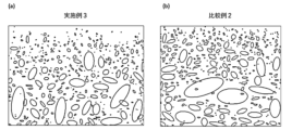
- (a) and (b) of FIG. 4 are images obtained by approximating ellipsoidal pore shapes in cross sections of the porous layers of Example 3 and Comparative Example 2, respectively.
- composite semipermeable membrane As one embodiment of the present invention, hereinafter, as shown in FIG.
- the composite semipermeable membrane 1 having and will be described.
- the composite semipermeable membrane only needs to have a porous layer and a separation function layer provided on the porous layer, and the substrate is not an essential requirement.
- Substrate should only provide strength to the composite semipermeable membrane and have sufficient water permeability.
- a known technique for composite semipermeable membranes can be applied.
- substrates include fabrics composed of polymers such as polyesters, polyamides, polyolefins, or mixtures or copolymers thereof.
- the base material is a nonwoven fabric.
- the thickness of the substrate is preferably in the range of 10-200 ⁇ m, more preferably in the range of 30-150 ⁇ m.
- the pure water permeability coefficient of the substrate at 25° C. is preferably 200 to 700 [10 ⁇ 9 m 3 /m 2 /s/Pa]. When the pure water permeability coefficient is within this range, it is easy to form a "flow", which will be described later, in the resin solution when forming the porous layer.
- the porous layer is preferably made of a thermoplastic resin.
- the thermoplastic resin is made of a chain polymer substance, and is a resin that exhibits the property of being deformed or fluidized by an external force when heated.
- thermoplastic resins include homopolymers or copolymers of polysulfone, polyethersulfone, polyamide, polyester, cellulosic polymer, vinyl polymer, polyphenylene sulfide, polyphenylene sulfide sulfone, polyphenylene sulfone, and polyphenylene oxide, either alone or in blends. can be used.
- Cellulose polymers such as cellulose acetate and cellulose nitrate
- vinyl polymers such as polyethylene, polypropylene, polyvinyl chloride, chlorinated vinyl chloride and polyacrylonitrile can be used.
- polysulfone, polyacrylonitrile, polyamide, polyester, polyvinyl alcohol, polyphenylene sulfide sulfone, polyphenylene sulfone, polyphenylene sulfide, polyether sulfone, polyvinylidene fluoride, cellulose acetate, polyvinyl chloride or chlorinated vinyl chloride are preferred.
- Cellulose acetate, polyvinyl chloride or chlorinated vinyl chloride, polysulfone, polyphenylene sulfide sulfone, or polyphenylene sulfone are more preferred, and among these materials, they have high chemical, mechanical, and thermal stability, Polysulfone is commonly used because it is easy to mold.
- the porous layer preferably contains these listed compounds as main components.
- Polysulfone preferably has a mass average molecular weight (Mw) of 10,000 or more and 200,000 or less, more preferably 10,000 or more and 200,000 or less, when measured by gel permeation chromatography (GPC) using N-methylpyrrolidone as a solvent and polystyrene as a standard substance. It is 15000 or more and 100000 or less.
- Mw mass average molecular weight
- the Mw of polysulfone is 10000 or more, it is possible to obtain mechanical strength and heat resistance preferable for the porous layer. Further, when the Mw is 200,000 or less, the viscosity of the solution is in an appropriate range, and good moldability can be achieved.
- the thickness of the porous layer is preferably 20 ⁇ m or more and 250 ⁇ m or less, more preferably 20 ⁇ m or more and 100 ⁇ m or less, or 30 ⁇ m or more and 50 ⁇ m or less.
- the thickness of the composite of the substrate and the porous layer is preferably 30 ⁇ m or more and 300 ⁇ m or less, It is more preferably 100 ⁇ m or more and 220 ⁇ m or less.
- the thickness means an average value.
- the average value represents an arithmetic mean value. That is, the thickness of the porous support is obtained by calculating the average value of 20 thicknesses measured at intervals of 2 cm in the direction perpendicular to the thickness direction (surface direction of the film) by cross-sectional observation.
- Pressurization under condition A is carried out by permeating an aqueous solution having a NaCl concentration of 3.2% by weight through the composite semipermeable membrane at 35° C. and 7 MPa for 6 hours.
- Pressurization under condition B is performed by permeating an aqueous solution having a NaCl concentration of 5.0% by weight through the composite semipermeable membrane at 45° C. and 7 MPa for 24 hours.
- Pressurization under condition C is performed by permeating an aqueous solution having a NaCl concentration of 3.2% by weight through the composite semipermeable membrane at 25° C. and 5.5 MPa for 2 hours.
- the porous layer (which may be a porous support) is covered with a non-permeable film such as a PTFE film on the surface of the porous layer. Then, pressure may be applied to the non-permeable film side with an aqueous solution under the same conditions.
- EA and EB Surface elastic modulus measured with an atomic force microscope (AFM) for the surface of the porous layer (separation functional layer side) pressurized under condition A, and the surface of the porous layer pressurized under condition B
- At least one of the surface layer elastic moduli EB measured for is preferably 0.60 GPa or more and 1.0 GPa or less.
- a composite semipermeable membrane including a porous layer having a surface layer elastic modulus within this range suppresses a decrease in water production even during high-temperature and/or high-pressure operation.
- At least one of the surface elastic moduli EA and EB is preferably 0.65 GPa or more and 1.0 GPa or less, more preferably 0.70 GPa or more and 0.95 GPa or less. In a preferred embodiment, both the surface elastic moduli EA and EB are 0.60 GPa or more and 1.0 GPa or less.
- the pores function as water permeation paths.
- compressive strength is proportional to elastic modulus and inversely proportional to porosity.
- porosity the higher the compressive strength, which suppresses crushing during high-temperature and/or high-pressure operation.
- the higher the porosity the greater the number of water permeation paths in the porous layer, so the water permeability is improved.
- the inventors focused on the surface layer structure that has the greatest effect on water permeability in the porous layer and conducted studies.
- the surface elastic moduli EA and EB are the elastic moduli in the submicron region from the surface layer of the porous layer. passage clogging) is suppressed, the water permeation path is maintained. As a result, it is possible to suppress a decrease in the water permeability of the porous layer and a decrease in the amount of water produced by the composite semipermeable membrane even when the membrane is operated at high temperature and/or high pressure.
- the surface layer elastic moduli EA and EB are values measured for the porous layer from which the separation function layer is removed and the surface is exposed.
- the removal of the separation functional layer may be performed either before or after pressurization under condition A or condition B.
- the porous layer (which may be a porous support) may be pressurized under condition A or condition B, or under condition A or condition B.
- the separation function layer may be removed from the pressurized composite semipermeable membrane.
- the surface elastic moduli EA and EB can be measured using an atomic force microscope (AFM). Specifically, a porous layer (which may be a porous support) is fixed on a slide glass, and the cantilever of an atomic force microscope is pressed against the surface of the porous layer and then released. The elastic modulus is calculated from the cantilever deflection amount and cantilever deformation amount read from the force curve and the spring coefficient of the cantilever obtained in advance. Details will be described later.
- AFM atomic force microscope
- the porous layer can have a surface layer elastic modulus EA or EB within the above range.
- the porous layer preferably satisfies two or more of the following conditions.
- Porosity is 10% to 30% in a portion from the surface layer to a depth of 500 nm. More preferably 12 to 25%.
- the portion from the surface to a depth of 500 nm is made of a thermoplastic resin that is more flexible than the portion exceeding the depth of 500 nm.
- the portion from the surface to a depth of 500 nm is polyvinyl chloride, and the portion beyond 500 nm is polysulfone.
- the ratio of pores in the thickness direction at a depth of 1.5 ⁇ m from the surface layer of the porous layer is 45% or more.
- the condition (c) is preferable because the pore paths are less likely to be clogged even after being pressurized in the film thickness direction and the surface layer voids can be maintained, so that the elastic modulus can be kept within the above range.
- the porous layer 3 has an asymmetric structure.
- the pore size is small on the surface on the separation functional layer side, and the pore size increases continuously or discontinuously toward the other surface along the thickness direction.
- the dense layer 31 the area where the resin ratio in the cross-sectional image is 90% or more is called the dense layer 31, and the portion where the resin ratio is less than 90% is called the coarse layer 32 ( Figure 2).
- the dense layer is determined as follows.
- the frozen composite semipermeable membrane is cleaved and the obtained cross section is observed.
- platinum/palladium or ruthenium tetroxide preferably ruthenium tetroxide
- platinum/palladium or ruthenium tetroxide is vapor-deposited on the cross section of the membrane to obtain an observation sample.
- a cross-section of the membrane is photographed at a magnification of 100,000 times using a field emission electron microscope to obtain an image.
- the image is converted to 8 bits by processing software, the minimum value of the threshold value is set to 0, the maximum value is set to 115, and binarization processing is performed to make black within the range and white otherwise.
- the ratio of black and white is calculated for every 20 nm from the surface layer, and the dense layer is defined as a range in which the black area per cross-sectional direction is 10% or less (that is, the porosity is 10% or less).
- the dense layer thickness d is preferably 300 nm or less, more preferably 200 nm or less.
- the dense layer 31 has a large resistance, a dense layer thickness d of 300 nm or less provides high water permeability even when operated at high pressure. As a result, it is possible to suppress a decrease in the amount of water produced by the composite semipermeable membrane.
- the lower limit of the dense layer thickness d of the pressurized porous layer is not specified, it is preferably 50 nm or more from the viewpoint of film strength.
- Specific means for achieving a dense layer thickness of 300 nm or less after pressing include: (a) increasing the strength of the support layer by, for example, adding a fiber material to the thermoplastic resin; (b) making the area ratio of the holes in the film thickness direction 45% or more; (c) an initial dense layer thickness of 100 nm or less; At least one, preferably two or more of are satisfied. In particular, it is preferable to satisfy (b) and (c).
- the above (a) and (b) can suppress crushing of the support layer.
- the above (c) can suppress the thickness of the dense layer after pressing to 300 nm or less even if the thickness of the dense layer increases due to crushing of the support layer by pressing.
- the ratio (RaA/RaC) and (RaB/RaC) is preferably 1.0 or more and 1.15 or less.
- the ratio (RaA/RaC) and (RaB/RaC) is preferably 1.0 or more and 1.15 or less.
- the area ratio of the holes in the thickness direction should be 45% or more.
- the area ratio of the holes in the film thickness direction is within this range, the entire film surface is uniformly compressed.
- the surface pore size of the porous layer is preferably 3 nm or more and 10 nm or less. As a result, the pore diameter of the surface in contact with the separation functional layer can be reduced, and the sagging of the separation functional layer can be suppressed.
- the pure water permeability coefficient of the porous layer (which may be a porous support) pressurized under condition A or condition B is 0.12 ( ⁇ 10 ⁇ 9 m 3 /(m 2 sec Pa)). It is preferable that it is above.
- the water permeability of the porous layer (which may be a porous support) after pressurization is 0.12 or more, the resistance of the porous layer in the composite semipermeable membrane is sufficiently small. As a result, it is possible to suppress the decrease in water production after high pressure operation with the composite semipermeable membrane during high pressure operation.
- the pure water permeability coefficient of the porous layer (which may be a porous support) pressurized under condition A or condition B is 0.12 ( ⁇ 10 ⁇ 9 m 3 /(m 2 ⁇ sec ⁇ Pa)) or more. In order to It is preferably 45% or more.
- the pure water permeability coefficient of the porous layer (which may be a porous support) pressurized under condition A or condition B is 0.15 ( ⁇ 10 ⁇ 9 m 3 /(m 2 sec Pa)). 0.20 or more is more preferable.
- ⁇ Area Ratio of Holes in Film Thickness Direction> A film cross section in the same direction as that for detecting the dense layer is photographed with a scanning transmission electron microscope (STEM). In the obtained image, the pores are approximated to an ellipse by image processing within a range of 1.5 ⁇ m from the surface of the porous layer (FIGS. 4(a) and 4(b)).
- a hole that is actually long in one direction may be recognized as an ellipse, or a plurality of adjacent small holes may be connected and recognized as one ellipse.
- holes having a major axis angle ⁇ of 45 degrees or more and 135 degrees or less with respect to the film surface direction are film thickness direction holes (FIG. 3).
- the area ratio of the holes in the film thickness direction is the ratio of the holes in the film thickness direction to the total area of all ellipsoidally approximated holes.
- the area ratio of the pores in the film thickness direction in the range of 1.5 ⁇ m deep from the surface of the porous layer is 45% or more.
- the water that has passed through the separation function layer passes through the pores of the porous layer and escapes to the base material. That is, the holes function as water passages.
- the film surface direction pore area ratio is 45% or more, even if pressure is applied in the film thickness direction and part of the porous layer is crushed, the water flow path in the film thickness direction is maintained. A decrease in water permeability can be suppressed.
- the preferable range of the area ratio of the holes in the film thickness direction is 45% or more and 90% or less, more preferably 65% or more and 80% or less.
- the separation functional layer contains a crosslinked aromatic polyamide.
- the separation functional layer preferably contains a crosslinked aromatic polyamide as a main component.
- the main component refers to a component that accounts for 50% by weight or more of the components of the separation functional layer.
- the separation functional layer can exhibit high removal performance.
- the content of the crosslinked aromatic polyamide in the separation functional layer is preferably 80% by weight or more, more preferably 90% by weight or more.
- a crosslinked aromatic polyamide can be formed by chemically reacting a polyfunctional aromatic amine and a polyfunctional aromatic acid chloride.
- at least one of the polyfunctional aromatic amine and the polyfunctional aromatic acid chloride preferably contains a trifunctional or higher compound. This results in a rigid molecular chain and a good pore structure for removing fine solutes such as hydrated ions and boron.
- a polyfunctional aromatic amine has two or more amino groups of at least one of a primary amino group and a secondary amino group in one molecule, and at least one of the amino groups is a primary It means an aromatic amine which is an amino group.
- polyfunctional aromatic amines include o-phenylenediamine, m-phenylenediamine, p-phenylenediamine, o-xylylenediamine, m-xylylenediamine, p-xylylenediamine, o-diaminopyridine, m- Diaminopyridine, p-diaminopyridine, etc.
- aliphatic amines such as ethylenediamine and propylenediamine, 1,2-diaminocyclohexane, 1,4-diaminocyclohexane, piperazine, 2,5-dimethylpiperazine, 2-methylpiperazine, 2,6-dimethylpiperazine, 2,3 ,5-trimethylpiperazine, 2,5-diethylpiperazine, 2,3,5-triethylpiperazine, 2-n-propylpiperazine, 2,5-di-n-butylpiperazine, 1,3-bispiperidylpropane, 4- Alicyclic polyfunctional amines such as aminomethylpiperazine and the like can be mentioned. These polyfunctional amines may be used alone or in combination.
- m-phenylenediamine, p-phenylenediamine, and 1,3,5-triaminobenzene are preferably used considering the selective separation, permeability and heat resistance of the membrane.
- m-phenylenediamine hereinafter also referred to as m-PDA
- polyfunctional aromatic amines may be used alone or in combination of two or more.
- a polyfunctional aromatic acid chloride refers to an aromatic acid chloride having at least two chlorocarbonyl groups in one molecule.
- trifunctional acid chlorides include trimesic acid chloride
- bifunctional acid chlorides include biphenyldicarboxylic acid dichloride, azobenzenedicarboxylic acid dichloride, terephthalic acid chloride, isophthalic acid chloride, and naphthalene dicarboxylic acid chloride. can be done.
- aliphatic bifunctional acid halides such as adipoyl chloride and sebacoyl chloride
- alicyclic bifunctional acid halides such as cyclopentanedicarboxylic acid dichloride, cyclohexanedicarboxylic acid dichloride, and tetrahydrofurandicarboxylic acid dichloride can be mentioned.
- These polyfunctional acid halides may be used alone or in combination.
- the membrane is preferably a polyfunctional aromatic acid chloride having 2 to 4 carbonyl chloride groups in one molecule.
- the method for producing a composite semipermeable membrane of the present invention comprises the steps of: (a) forming a resin solution in which a thermoplastic resin is dissolved in a good solvent into a flat film; A method for producing a composite semipermeable membrane comprising the steps of: obtaining a porous layer by solidifying the thermoplastic resin in a solidifying liquid containing The step (b) includes the step of forming a flow of the coagulating liquid in the thickness direction of the resin solution within 3 seconds after being immersed in the coagulating liquid.
- the step of forming the porous layer includes: (a) forming a resin solution obtained by dissolving a thermoplastic resin (hereinafter referred to as a resin) in a good solvent into a flat film; (b) obtaining a porous layer by solidifying the resin in a solidifying liquid containing a non-solvent and a good solvent for the resin;
- the step of forming the porous layer may further include a step of dissolving a resin, which is a component of the porous layer, in a good solvent for the resin to prepare a resin solution.
- Resin is a material that is the main component of the porous layer, and is specifically described above. The following conditions are particularly preferably applied when the resin is polysulfone.
- a “good solvent” is one that dissolves the resin.
- the rate of the good solvent flowing out of the resin solution in step (b) can be adjusted.
- the surface elastic modulus, dense layer thickness and surface roughness of the porous layer can be controlled.
- Good solvents include, for example, N-methyl-2-pyrrolidone (NMP), tetrahydrofuran (THF), dimethylsulfoxide (DMSO), tetramethylurea (THU), N,N-dimethylacetamide (DMAc).
- NMP N-methyl-2-pyrrolidone
- THF tetrahydrofuran
- DMSO dimethylsulfoxide
- TU tetramethylurea
- DMAc N,N-dimethylacetamide
- N,N- Amides such as dimethylformamide (DMF), N,N-dimethylisobutyramide (DMIB), N,N-diisopropylisobutyramide, N,N-bis(2-ethylhexyl)isobutyramide; lower grades such as acetone and methyl ethyl ketone (MEK)
- the step (a) can be performed by applying a resin solution onto the substrate or the base material described above, or by immersing the base material in a resin solution.
- the porous layer is separated from the substrate after step (b).
- Application of the resin solution onto the substrate or base material can be carried out by various coating methods, but pre-metered coating methods such as die coating, slide coating, curtain coating, etc., which can apply an accurate amount of solution, are preferably applied. Furthermore, in forming the porous layer, a slit die method of applying a resin solution is more preferably used.
- the resin concentration concentration (that is, solid content concentration) in the resin solution is preferably 15% by weight or more, more preferably 16% by weight or more, and still more preferably 17% by weight or more. Also, the resin concentration is preferably 30% by weight or less, more preferably 25% by weight or less, and even more preferably 20% by weight or less.
- the resin concentration is 15% by weight or more, and the area ratio of the pores in the film thickness direction in the range from the surface of the porous layer to the depth of 1.5 ⁇ m is 45% or more, so that the value of the surface layer elastic modulus is 0.6 GPa. You can do more than that.
- the area ratio of the holes in the film thickness direction can be adjusted by setting the resin concentration within the above range and by forming the flow of the coagulating liquid as described later. Further, when the area ratio of the holes in the thickness direction is in the same range and the resin concentration is 17% by weight or more, the surface layer elastic modulus can be 0.7 GPa or more.
- the composite semipermeable membrane can have good initial water production and post-pressurization water production.
- the temperature of the resin solution when applied to the substrate is preferably within the range of 10 to 60°C. Within this range, the resin solution is solidified after sufficiently impregnating between the fibers of the base material without depositing the resin solution. As a result, the porous layer can be firmly bonded to the base material by impregnation, and the porous layer can be obtained.
- the preferable temperature range of the resin solution may be appropriately adjusted according to the viscosity of the resin solution used.
- the solvent contained in the resin solution may be the same solvent or different solvents as long as they are good solvents for the resin. It can be appropriately adjusted in consideration of the strength characteristics of the porous layer to be produced and the impregnation of the base material with the resin solution.
- the resin solution may contain additives for adjusting the dense layer, void layer, pore size, porosity, hydrophilicity, elastic modulus, etc. of the porous layer.
- Additives for adjusting the pore size and porosity include water, alcohols, polyethylene glycol, polyvinylpyrrolidone, polyvinyl alcohol, water-soluble polymers such as polyacrylic acid and salts thereof, lithium chloride, sodium chloride, chloride Examples include, but are not limited to, inorganic salts such as calcium and lithium nitrate, formaldehyde, formamide, and the like.
- Additives for adjusting hydrophilicity and elastic modulus include various surfactants.
- the base material is impregnated with the resin solution as described above.
- the impregnation of the substrate with the resin solution for example, after the substrate is coated with the resin solution, it is possible to control the time until the substrate is immersed in the coagulation liquid (coagulation bath), or the temperature of the resin solution can be controlled.
- coagulation liquid coagulation bath
- a method of adjusting the viscosity by controlling the concentration may be mentioned, and it is also possible to combine these methods.
- step (b) the resin solution placed on the substrate is immersed in a coagulating liquid having a lower resin solubility than the good solvent in the resin solution to solidify the resin, thereby forming a three-dimensional network structure. be able to.
- the concentration of the good solvent in the coagulation liquid is preferably 0.5% by weight or more, 5% by weight or more, or 10% by weight or more, and 50% by weight or less, or 30% by weight or less.
- the types of good solvents are as described above.
- the concentration of the non-solvent in the coagulation liquid is preferably 50% by weight or more or 70% by weight or more, and preferably 95% by weight or less or 90% by weight or less.
- non-solvents include water, hexane, pentane, benzene, toluene, methanol, ethanol, trichlorethylene, ethylene glycol, diethylene glycol, triethylene glycol, propylene glycol, butylene glycol, pentanediol, hexanediol, and low molecular weight polyethylene glycol.
- step (b) includes forming a solidified liquid flow in the thickness direction in the resin solution at the initial stage of phase separation.
- the initial stage of phase separation is the period from when the resin solution is immersed in the coagulating liquid to when the coagulation is completed. For example, within 3 seconds after immersion in the coagulating liquid, preferably within 2 seconds, more preferably 1 second. within.
- the area ratio of the pores in the film thickness direction can be improved.
- the coagulation liquid is forced from the substrate side toward the resin solution (that is, from the back surface of the substrate), or from the substrate side (from the substrate side). (from the back) to aspirate the coagulation liquid.
- the pushing or sucking pressure for forming the flow is preferably 1-3 kPa.
- the duration of pushing or sucking is preferably 3-10 seconds.
- the liquid temperature of the coagulation liquid is preferably within the range of 5-50°C, more preferably 5-30°C. If the temperature is 50° C. or less, the vibration of the solidified liquid surface due to thermal motion does not increase, and the smoothness of the surface of the porous layer increases. Further, when the temperature is 5° C. or higher, a sufficient solidification rate is obtained, and the film formability is good.
- the surface pore diameter can be set to 3 nm or more and 10 nm or less.
- the obtained porous support is preferably washed with hot water to remove the membrane-forming solvent remaining in the membrane.
- the temperature of the hot water at this time is preferably 50 to 100°C, more preferably 60 to 95°C. By washing at 100° C. or less, the degree of shrinkage of the porous support can be suppressed. By washing at 50°C or higher, a high washing effect can be obtained.
- the separation functional layer is obtained by chemically reacting a polyfunctional aromatic amine and a polyfunctional aromatic acid chloride to form a crosslinked aromatic polyamide.
- the chemical reaction method the interfacial polymerization method is most preferable from the viewpoint of productivity and performance. That is, the separation functional layer is formed by interfacial polycondensation on the surface of the porous layer using an aqueous solution containing a polyfunctional amine and an organic solvent containing a polyfunctional acid halide. This step forms a crosslinked polyamide.
- the step of interfacial polymerization includes step (i) of bringing an aqueous solution containing a polyfunctional aromatic amine into contact with the porous layer, and after step (i), dissolving the polyfunctional aromatic acid chloride. and a step (ii) of contacting the solution with the porous layer.
- the concentration of the polyfunctional aromatic amine in the polyfunctional aromatic amine aqueous solution is preferably in the range of 0.1% by weight or more and 20% by weight or less, more preferably 0.5% by weight or more and 15% by weight. It is within the range of weight % or less. If the concentration of the polyfunctional aromatic amine is within this range, sufficient solute removal performance and water permeability can be obtained.
- the contact of the polyfunctional aromatic amine aqueous solution is preferably carried out uniformly and continuously on the porous layer.
- Specific examples include a method of coating the porous layer with an aqueous polyfunctional aromatic amine solution, a method of immersing the porous layer in an aqueous polyfunctional aromatic amine solution, and the like.
- the contact time between the porous layer and the polyfunctional aromatic amine aqueous solution is preferably from 1 second to 10 minutes, more preferably from 10 seconds to 3 minutes.
- the support film after contact with the polyfunctional aromatic amine aqueous solution is held in the vertical direction and the excess aqueous solution is allowed to flow naturally, or an air flow such as nitrogen is blown from an air nozzle to forcibly drain. and the like can be used. Also, after draining, the film surface can be dried to partially remove water from the aqueous solution.
- the concentration of the polyfunctional aromatic acid chloride in the organic solvent solution is preferably in the range of 0.01% by weight or more and 10% by weight or less, and 0.02% by weight or more and 2.0% by weight. It is more preferable that it is within the following range. This is because a content of 0.01% by weight or more provides a sufficient reaction rate, and a content of 10% by weight or less can suppress the occurrence of side reactions.
- the organic solvent is preferably one that is immiscible with water, dissolves the polyfunctional aromatic acid chloride, does not destroy the support film, and is inert to the polyfunctional aromatic amine and the polyfunctional aromatic acid chloride. Anything is fine.
- Preferred examples include hydrocarbon compounds such as n-nonane, n-decane, n-undecane, n-dodecane, isooctane, isodecane and isododecane, and mixed solvents.
- the method of contacting the porous layer in which the organic solvent solution of the polyfunctional aromatic acid chloride is brought into contact with the polyfunctional aromatic amine aqueous solution is the same as the method of coating the porous layer with the polyfunctional aromatic amine aqueous solution. good.
- the organic solvent is removed from the film surface.
- the organic solvent can be removed, for example, by holding the membrane vertically and removing the excess organic solvent by gravity, by blowing air with a blower to dry and remove the organic solvent, or by using a mixed fluid of water and air. can be used to remove the excess organic solvent.
- an aliphatic amine or an alicyclic polyfunctional amine may be used instead of the polyfunctional aromatic amine, and an aliphatic difunctional compound may be used instead of the polyfunctional aromatic acid chloride.
- Acid halides or cycloaliphatic difunctional acid halides may be used to form crosslinked aliphatic or cycloaliphatic polyamides.
- the composite semipermeable membrane It is preferably used as a spiral-type composite semipermeable membrane element wound around a cylindrical water collection tube with holes. Furthermore, a composite semipermeable membrane module in which these elements are connected in series or in parallel and housed in a pressure vessel can also be formed.
- the above composite semipermeable membranes, their elements, and modules can be combined with a pump that supplies water to them, a device that preprocesses the water, and the like to form a fluid separation device.
- a separator By using this separator, it is possible to separate feed water into permeated water such as drinking water and concentrated water that has not permeated the membrane, thereby obtaining desired water.
- feed water examples include liquid mixtures containing 500 mg/L or more and 100 g/L or less of TDS (Total Dissolved Solids) such as seawater, brackish water, and waste water.
- TDS Total Dissolved Solids
- mass/volume or "weight ratio”.
- the solution filtered through a 0.45 micron filter is evaporated at a temperature of 39.5 ° C to 40.5 ° C and can be calculated from the weight of the residue, but more conveniently the practical salinity (S) Convert from
- the operating pressure during permeation is preferably 0.5 MPa or more and 12 MPa or less.
- scale such as magnesium may be generated in the case of feed water with a high solute concentration such as seawater. Driving in is preferred.
- NaCl removal rate (%) 100 ⁇ ⁇ 1-(NaCl concentration in permeate water/NaCl concentration in feed water) ⁇
- the boron removal rate is calculated based on the following formula.
- Boron removal rate (%) 100 ⁇ ⁇ 1-(boron concentration in permeate water/boron concentration in feed water) ⁇
- the concentration of boron in raw water and permeated water can be measured by taking a sample liquid for measuring desalination performance and using an ICP emission spectrometer (5110 ICP-OES manufactured by Agilent Technologies).
- the isopropyl alcohol removal rate of the composite semipermeable membrane is obtained as follows. A 1000 ppm isopropyl alcohol aqueous solution prepared at a temperature of 25 ° C. and pH 6.5 was supplied to the composite semipermeable membrane at an operating pressure of 0.75 MPa and a concentrated water flow rate of 3.5 L / min. Evaluate by comparison. That is, the isopropyl alcohol removal rate (%) is calculated as follows: 100 ⁇ (1 ⁇ (isopropyl alcohol concentration in permeate water/isopropyl alcohol concentration in feed water)). The isopropyl alcohol concentration is determined using a gas chromatograph (GC-18A manufactured by Shimadzu Corporation).
- the isopropyl alcohol removal rate of the composite semipermeable membrane is preferably 70% or less, more preferably 65% or less. Although the lower limit is not particularly limited, it is, for example, 5%.
- the glucose removal rate of the composite semipermeable membrane is determined as follows. A 1000 ppm glucose aqueous solution prepared at a temperature of 25° C. and a pH of 6.5 was supplied to the composite semipermeable membrane at an operating pressure of 0.75 MPa and a concentrated water flow rate of 3.5 L/min. Evaluate by That is, the glucose removal rate (%) is calculated as follows: 100 ⁇ (1 ⁇ (glucose concentration in permeate water/glucose concentration in feed water)). The glucose concentration is determined by a refractometer (RID-6A manufactured by Shimadzu Corporation).
- the glucose removal rate of the composite semipermeable membrane is preferably 90% or more from the viewpoint of separation of alkali metal salts.
- the upper limit is not particularly limited, it is, for example, 99.9%.
- the (glucose removal rate-isopropyl alcohol removal rate) is preferably 30% or more from the viewpoint of separation of alkali metal salts.
- the upper limit is not particularly limited, but is, for example, 50%.
- separation functional layer was removed by immersing the composite semipermeable membrane prepared as described below in a 2 wt % sodium hypochlorite aqueous solution at 20° C. for 24 hours.
- the pressurized porous support was frozen by immersion in liquid nitrogen as a pretreatment for maintaining the porous shape, then cut and dried.
- Threshold the minimum value of the threshold was set to 0 and the maximum value was set to 115, and binarization processing was performed with black within the range and white otherwise. Among them, the ratio of black and white was calculated for each 20 nm from the surface, and the dense layer thickness was defined as the range in which the black area per cross-sectional direction was less than 10%.
- Apparatus field emission electron microscope JEM-F200 (manufactured by JEOL)
- ⁇ Measurement conditions acceleration voltage of 200 kV
- a range of width 1800 nm ⁇ depth 1500 nm was selected with a position 10 nm deep from the surface as the upper end, and the area other than the selected range was deleted by “Crop”.
- select "Area” in “Set Measurements” For the image of the area thus selected, select "Area” in “Set Measurements”, further select “Fit ellipse”, and perform particle analysis with “Analyze Particles”.
- the hollow part of the particle was also included in the area of the particle.
- FIGS. 4(a) and 4(b) The results of elliptical approximation of Example 3 and Comparative Example 2 are shown in FIGS. 4(a) and 4(b). According to the results obtained by the analysis thus obtained, holes with an angle of 45 degrees or more and 135 degrees or less were defined as holes in the thickness direction.
- Area ratio of holes in thickness direction Total area of holes in thickness direction / Total area of all holes
- Porosity at a portion from the surface of the porous membrane to a depth of 500 nm As a pretreatment for maintaining the porous shape, the membrane sample was immersed in liquid nitrogen and frozen, then cut and dried. A thin film of platinum/palladium or ruthenium tetroxide, preferably ruthenium tetroxide, is deposited on the cross section of the film to obtain an observation sample. After that, the photographing magnification is set to 100,000 times, and an arbitrary cross-sectional photograph of the membrane cross section is obtained. With respect to the range of this cross-sectional photograph, the film cross-sectional photograph image in the range of 500 nm from the surface is read with image-J, and the type is set to 8 bits in image. With Threshold, the minimum value of the threshold value was set to 0 and the maximum value to 115, and binarization processing was performed with black within the range and white otherwise, and the black portion area ratio was taken as the porosity.
- NaCl removal rate (%) 100 ⁇ ⁇ 1-(NaCl concentration in permeate water/NaCl concentration in feed water) ⁇
- the boron removal rate is calculated based on the following formula.
- Boron removal rate (%) 100 ⁇ ⁇ 1-(boron concentration in permeate water/boron concentration in feed water) ⁇
- the boron concentrations in raw water and permeated water were measured using an ICP emission spectrometer (5110 ICP-OES manufactured by Agilent Technologies, Inc.) after collecting sample liquids for desalination performance measurement.
- Isopropyl alcohol removal rate (10) Glucose removal rate, isopropyl alcohol removal rate (10-1) Isopropyl alcohol removal rate A 1000 ppm isopropyl alcohol aqueous solution prepared at a temperature of 25 ° C. and pH 6.5 was applied to a composite semipermeable membrane at an operating pressure of 0.75 MPa and a concentrated water flow rate. Evaluation was made by comparing the isopropyl alcohol concentrations of permeated water and feed water when supplied at 3.5 L/min. That is, the isopropyl alcohol removal rate (%) was calculated as follows: 100 ⁇ (1 ⁇ (concentration of isopropyl alcohol in permeated water/concentration of isopropyl alcohol in feed water)). The isopropyl alcohol concentration was determined using a gas chromatograph (GC-18A manufactured by Shimadzu Corporation).
- Glucose removal rate A 1000 ppm glucose aqueous solution prepared at a temperature of 25 ° C. and pH 6.5 was supplied to the composite semipermeable membrane at an operating pressure of 0.75 MPa and a concentrated water flow rate of 3.5 L / min. It was evaluated by comparing the glucose concentration of the feed water. That is, the glucose removal rate (%) was calculated as follows: 100 ⁇ (1 ⁇ (glucose concentration in permeate water/glucose concentration in feed water)). The glucose concentration was determined using a refractometer (RID-6A manufactured by Shimadzu Corporation).
- MgSO 4 removal rate (%) 100 ⁇ ⁇ 1-(MgS0 4 concentration in permeate/MgS0 4 concentration in feed water) ⁇
- MgSO 4 removal rate (%) 100 ⁇ ⁇ 1-(MgS0 4 concentration in permeate/MgS0 4 concentration in feed water) ⁇
- Example 1 A 15% by weight DMF solution of polysulfone (PSf) was cast on a polyester nonwoven fabric (thickness 90 ⁇ m, water permeability 700 [10 ⁇ 9 m 3 /m 2 /s/Pa]) as a substrate at 25° C., Within 1.0 second after immersion in pure water, pure water was pressed from the substrate side for about 3 seconds at a pressure of 1 kPa, and then left in pure water for 5 minutes to prepare a porous support. The thickness of the polysulfone layer was 40 ⁇ m.
- the obtained porous support was immersed in a 3% by weight aqueous solution of m-phenylenediamine (m-PDA) for 2 minutes, the support was slowly lifted vertically, and nitrogen was blown from an air nozzle to the surface of the support film. After removing the excess aqueous solution, a decane solution containing 0.165% by weight of trimesic acid chloride (TMC) was applied so that the surface was completely wetted and allowed to stand for 1 minute. A composite semipermeable membrane having a crosslinked aromatic polyamide separation functional layer was obtained by draining off the liquid and washing with pure water.
- m-PDA m-phenylenediamine
- Example 2 A composite semipermeable membrane having a crosslinked aromatic polyamide separation functional layer was obtained in the same manner as in Example 1, except that the polysulfone concentration was changed to 16% by weight.
- Example 3 A composite semipermeable membrane having a crosslinked aromatic polyamide separation functional layer was obtained in the same manner as in Example 1, except that the polysulfone concentration was changed to 17% by weight.
- Example 4 A composite semipermeable membrane having a crosslinked aromatic polyamide separation function layer was obtained in the same manner as in Example 1, except that the polysulfone concentration was changed to 18% by weight.
- Example 5 A composite semipermeable membrane having a crosslinked aromatic polyamide separation functional layer was obtained in the same manner as in Example 4, except that pure water was pressed from the substrate side at a pressure of 3 kPa for about 10 seconds.
- Example 6 An 18% by weight DMF solution of polysulfone (PSf) was cast on a polyester nonwoven fabric (thickness 90 ⁇ m, water permeability 700 [10 ⁇ 9 m 3 /m 2 /s/Pa]) at 25° C., and then immersed in pure water. At the same time as the immersion, pure water was sucked from the substrate side at a pressure of 1 kPa for about 10 seconds, and then left in the pure water for 5 minutes to prepare a porous support. The thickness of the polysulfone layer was 40 ⁇ m. A composite semipermeable membrane having a crosslinked aromatic polyamide separation functional layer was obtained in the same manner as in Example 1 except for the above.
- PSf polysulfone
- Example 7 A composite semipermeable membrane having a crosslinked aromatic polyamide separation function layer was obtained in the same manner as in Example 1, except that the concentration of polysulfone was changed to 21% by weight.
- Example 8 First, in the same manner as in Example 1, a porous support was produced. The obtained porous support was immersed in an aqueous solution containing 1.0% by weight of piperazine and 100 ppm of sodium dodecyldiphenyletherdisulfonate for 30 seconds. Excess aqueous solution was removed from the surface of the porous layer by blowing nitrogen from the porous layer. Next, a decane solution containing 0.40% by weight of trimesic acid chloride (TMC) was applied so that the surface of the porous layer was completely wetted and allowed to stand for 30 seconds. The decane solution was dried by blowing air at 25° C. using an air blower. Finally, by washing with pure water at 80° C., a composite separation membrane having a crosslinked aliphatic polyamide separation functional layer was obtained.
- TMC trimesic acid chloride
- Example 9 A porous support was prepared in the same manner as in Example 3. Thereafter, in the same manner as in Example 8, a composite semipermeable membrane having a crosslinked aliphatic polyamide separation functional layer was obtained.
- Example 10 A composite semipermeable fabric having a crosslinked aromatic polyamide separation function layer was used in the same manner as in Example 4 except that a polyester nonwoven fabric (thickness 90 ⁇ m, water permeability 200 [10 ⁇ 9 m 3 /m 2 /s/Pa]) was used as the base material. A membrane was obtained.
- Example 11 A composite semipermeable fabric having a crosslinked aromatic polyamide separation function layer was used in the same manner as in Example 5 except that a polyester nonwoven fabric (thickness 90 ⁇ m, water permeability 200 [10 ⁇ 9 m 3 /m 2 /s/Pa]) was used as the base material. A membrane was obtained.
- Comparative example 1 A 16% by weight DMF solution of polysulfone (PSf) was cast on a polyester nonwoven fabric (thickness 90 ⁇ m, water permeability 700 [10 ⁇ 9 m 3 /m 2 /s/Pa]) at 25° C., and immediately immersed in pure water. A porous support was prepared by immersing in and leaving for 5 minutes. The thickness of the polysulfone layer was 40 ⁇ m.
- a composite semipermeable membrane having a crosslinked aromatic polyamide separation functional layer was obtained in the same manner as in Example 1 except for the above.
- Comparative example 2 A composite semipermeable membrane having a crosslinked aromatic polyamide separation function layer was obtained in the same manner as in Comparative Example 1, except that the polysulfone concentration was changed to 17% by weight.
- Comparative Example 4 An 18% by weight DMF solution of polysulfone (PSf) was cast on a polyester nonwoven fabric (thickness 90 ⁇ m, water permeability 700 [10 ⁇ 9 m 3 /m 2 /s/Pa]) at 25° C., and then immersed in pure water. Within 1.0 second after immersion, pure water was pressed from the substrate side for about 3 seconds at a pressure of 1 kPa, and then left in pure water for 5 minutes to prepare a porous support.
- PSf polysulfone
- a PTFE film having a thickness of 0.1 mm is laminated on the thermoplastic resin layer side of the porous support so that the raw water permeates the porous support and the composite semipermeable membrane in this order, Membrane filtration was performed for 2 hours at an operating pressure of 5.5 MPa, and then membrane filtration was performed at a temperature of 35° C. and an operating pressure of 7.0 MPa for 6 hours to obtain a porous support.
- the obtained porous support was immersed in a 3% by weight aqueous solution of m-phenylenediamine (m-PDA) for 2 minutes, the support was slowly lifted vertically, and nitrogen was blown from an air nozzle to the surface of the support film.
- m-PDA m-phenylenediamine
- TMC trimesic acid chloride
- the composite semipermeable membrane of the present invention is used for desalination of seawater, desalination of brackish water, production of drinking water, production of industrial ultrapure water, wastewater treatment, recovery of valuables, and the like.
Landscapes
- Chemical & Material Sciences (AREA)
- Chemical Kinetics & Catalysis (AREA)
- Engineering & Computer Science (AREA)
- Dispersion Chemistry (AREA)
- Manufacturing & Machinery (AREA)
- Water Supply & Treatment (AREA)
- Life Sciences & Earth Sciences (AREA)
- Hydrology & Water Resources (AREA)
- Environmental & Geological Engineering (AREA)
- Organic Chemistry (AREA)
- Nanotechnology (AREA)
- Separation Using Semi-Permeable Membranes (AREA)
Priority Applications (4)
| Application Number | Priority Date | Filing Date | Title |
|---|---|---|---|
| JP2023509446A JP7343075B1 (ja) | 2022-01-26 | 2023-01-26 | 複合半透膜及び複合半透膜の製造方法 |
| US18/833,105 US20250256247A1 (en) | 2022-01-26 | 2023-01-26 | Composite semipermeable membrane and method for producing composite semipermeable membrane |
| CN202380018316.0A CN118591413A (zh) | 2022-01-26 | 2023-01-26 | 复合半透膜及复合半透膜的制造方法 |
| KR1020247024596A KR102739465B1 (ko) | 2022-01-26 | 2023-01-26 | 복합 반투막 및 복합 반투막의 제조 방법 |
Applications Claiming Priority (2)
| Application Number | Priority Date | Filing Date | Title |
|---|---|---|---|
| JP2022-009924 | 2022-01-26 | ||
| JP2022009924 | 2022-01-26 |
Publications (1)
| Publication Number | Publication Date |
|---|---|
| WO2023145845A1 true WO2023145845A1 (ja) | 2023-08-03 |
Family
ID=87471578
Family Applications (1)
| Application Number | Title | Priority Date | Filing Date |
|---|---|---|---|
| PCT/JP2023/002534 Ceased WO2023145845A1 (ja) | 2022-01-26 | 2023-01-26 | 複合半透膜及び複合半透膜の製造方法 |
Country Status (5)
| Country | Link |
|---|---|
| US (1) | US20250256247A1 (https=) |
| JP (1) | JP7343075B1 (https=) |
| KR (1) | KR102739465B1 (https=) |
| CN (1) | CN118591413A (https=) |
| WO (1) | WO2023145845A1 (https=) |
Cited By (1)
| Publication number | Priority date | Publication date | Assignee | Title |
|---|---|---|---|---|
| WO2025225556A1 (ja) * | 2024-04-22 | 2025-10-30 | 東レ株式会社 | 複合半透膜およびその製造方法、分離膜エレメントならびに流体分離装置 |
Families Citing this family (1)
| Publication number | Priority date | Publication date | Assignee | Title |
|---|---|---|---|---|
| WO2025116012A1 (ja) * | 2023-11-30 | 2025-06-05 | 東レ株式会社 | 複合半透膜の性能変化解析法、複合半透膜の性能変化解析プログラム及び記録媒体 |
Citations (4)
| Publication number | Priority date | Publication date | Assignee | Title |
|---|---|---|---|---|
| JP2017109202A (ja) * | 2015-12-14 | 2017-06-22 | 日東電工株式会社 | 水素排出膜形成用支持体及び水素排出積層膜 |
| JP2018039003A (ja) * | 2016-08-31 | 2018-03-15 | 東レ株式会社 | 複合半透膜およびその製造方法 |
| JP2019177342A (ja) * | 2018-03-30 | 2019-10-17 | 東レ株式会社 | 複合半透膜 |
| JP2021023928A (ja) * | 2019-08-02 | 2021-02-22 | 東レ株式会社 | 分離膜およびその製造方法 |
Family Cites Families (2)
| Publication number | Priority date | Publication date | Assignee | Title |
|---|---|---|---|---|
| JP2001252538A (ja) | 2000-03-10 | 2001-09-18 | Toray Ind Inc | 逆浸透複合膜 |
| JP2014014739A (ja) | 2012-07-06 | 2014-01-30 | Toray Ind Inc | 複合半透膜エレメントの製造方法および複合半透膜エレメント |
-
2023
- 2023-01-26 WO PCT/JP2023/002534 patent/WO2023145845A1/ja not_active Ceased
- 2023-01-26 KR KR1020247024596A patent/KR102739465B1/ko active Active
- 2023-01-26 JP JP2023509446A patent/JP7343075B1/ja active Active
- 2023-01-26 US US18/833,105 patent/US20250256247A1/en active Pending
- 2023-01-26 CN CN202380018316.0A patent/CN118591413A/zh active Pending
Patent Citations (4)
| Publication number | Priority date | Publication date | Assignee | Title |
|---|---|---|---|---|
| JP2017109202A (ja) * | 2015-12-14 | 2017-06-22 | 日東電工株式会社 | 水素排出膜形成用支持体及び水素排出積層膜 |
| JP2018039003A (ja) * | 2016-08-31 | 2018-03-15 | 東レ株式会社 | 複合半透膜およびその製造方法 |
| JP2019177342A (ja) * | 2018-03-30 | 2019-10-17 | 東レ株式会社 | 複合半透膜 |
| JP2021023928A (ja) * | 2019-08-02 | 2021-02-22 | 東レ株式会社 | 分離膜およびその製造方法 |
Cited By (2)
| Publication number | Priority date | Publication date | Assignee | Title |
|---|---|---|---|---|
| WO2025225556A1 (ja) * | 2024-04-22 | 2025-10-30 | 東レ株式会社 | 複合半透膜およびその製造方法、分離膜エレメントならびに流体分離装置 |
| JP7835349B1 (ja) * | 2024-04-22 | 2026-03-25 | 東レ株式会社 | 複合半透膜およびその製造方法、分離膜エレメントならびに流体分離装置 |
Also Published As
| Publication number | Publication date |
|---|---|
| US20250256247A1 (en) | 2025-08-14 |
| KR102739465B1 (ko) | 2024-12-11 |
| CN118591413A (zh) | 2024-09-03 |
| KR20240121881A (ko) | 2024-08-09 |
| JP7343075B1 (ja) | 2023-09-12 |
| JPWO2023145845A1 (https=) | 2023-08-03 |
Similar Documents
| Publication | Publication Date | Title |
|---|---|---|
| JP6197649B2 (ja) | 複合半透膜 | |
| JP5978998B2 (ja) | 複合半透膜、複合半透膜エレメントおよび複合半透膜の製造方法 | |
| JP6052172B2 (ja) | 複合半透膜の製造方法 | |
| CN102105214B (zh) | 复合半透膜及其制造方法 | |
| JP2018039003A (ja) | 複合半透膜およびその製造方法 | |
| JP6197969B1 (ja) | 複合半透膜 | |
| JP2019098330A (ja) | 複合半透膜およびその製造方法 | |
| JP7343075B1 (ja) | 複合半透膜及び複合半透膜の製造方法 | |
| JPWO2014133133A1 (ja) | 複合半透膜 | |
| JP6237233B2 (ja) | 複合半透膜および複合半透膜エレメント | |
| CN108025265B (zh) | 复合半透膜 | |
| JP7835349B1 (ja) | 複合半透膜およびその製造方法、分離膜エレメントならびに流体分離装置 | |
| JP2014188407A (ja) | 複合半透膜 | |
| JP2025126116A (ja) | 複合半透膜 | |
| JP2024143504A (ja) | 複合半透膜および造水方法 | |
| WO2026070495A1 (ja) | 複合半透膜および複合半透膜を備える分離膜エレメント |
Legal Events
| Date | Code | Title | Description |
|---|---|---|---|
| WWE | Wipo information: entry into national phase |
Ref document number: 2023509446 Country of ref document: JP |
|
| 121 | Ep: the epo has been informed by wipo that ep was designated in this application |
Ref document number: 23747055 Country of ref document: EP Kind code of ref document: A1 |
|
| ENP | Entry into the national phase |
Ref document number: 20247024596 Country of ref document: KR Kind code of ref document: A |
|
| WWE | Wipo information: entry into national phase |
Ref document number: 202380018316.0 Country of ref document: CN |
|
| NENP | Non-entry into the national phase |
Ref country code: DE |
|
| 122 | Ep: pct application non-entry in european phase |
Ref document number: 23747055 Country of ref document: EP Kind code of ref document: A1 |
|
| WWP | Wipo information: published in national office |
Ref document number: 18833105 Country of ref document: US |