WO2023145803A1 - 異常予兆検知機能付ケーブルおよび電線異常予兆検知システム - Google Patents
異常予兆検知機能付ケーブルおよび電線異常予兆検知システム Download PDFInfo
- Publication number
- WO2023145803A1 WO2023145803A1 PCT/JP2023/002386 JP2023002386W WO2023145803A1 WO 2023145803 A1 WO2023145803 A1 WO 2023145803A1 JP 2023002386 W JP2023002386 W JP 2023002386W WO 2023145803 A1 WO2023145803 A1 WO 2023145803A1
- Authority
- WO
- WIPO (PCT)
- Prior art keywords
- wire
- life
- conductor
- detection
- short
- Prior art date
- Legal status (The legal status is an assumption and is not a legal conclusion. Google has not performed a legal analysis and makes no representation as to the accuracy of the status listed.)
- Ceased
Links
Images


Classifications
-
- G—PHYSICS
- G01—MEASURING; TESTING
- G01R—MEASURING ELECTRIC VARIABLES; MEASURING MAGNETIC VARIABLES
- G01R31/00—Arrangements for testing electric properties; Arrangements for locating electric faults; Arrangements for electrical testing characterised by what is being tested not provided for elsewhere
- G01R31/50—Testing of electric apparatus, lines, cables or components for short-circuits, continuity, leakage current or incorrect line connections
- G01R31/58—Testing of lines, cables or conductors
-
- G—PHYSICS
- G01—MEASURING; TESTING
- G01R—MEASURING ELECTRIC VARIABLES; MEASURING MAGNETIC VARIABLES
- G01R31/00—Arrangements for testing electric properties; Arrangements for locating electric faults; Arrangements for electrical testing characterised by what is being tested not provided for elsewhere
- G01R31/50—Testing of electric apparatus, lines, cables or components for short-circuits, continuity, leakage current or incorrect line connections
- G01R31/54—Testing for continuity
-
- H—ELECTRICITY
- H01—ELECTRIC ELEMENTS
- H01B—CABLES; CONDUCTORS; INSULATORS; SELECTION OF MATERIALS FOR THEIR CONDUCTIVE, INSULATING OR DIELECTRIC PROPERTIES
- H01B7/00—Insulated conductors or cables characterised by their form
- H01B7/04—Flexible cables, conductors, or cords, e.g. trailing cables
-
- H—ELECTRICITY
- H01—ELECTRIC ELEMENTS
- H01B—CABLES; CONDUCTORS; INSULATORS; SELECTION OF MATERIALS FOR THEIR CONDUCTIVE, INSULATING OR DIELECTRIC PROPERTIES
- H01B7/00—Insulated conductors or cables characterised by their form
- H01B7/32—Insulated conductors or cables characterised by their form with arrangements for indicating defects, e.g. breaks or leaks
-
- H—ELECTRICITY
- H01—ELECTRIC ELEMENTS
- H01B—CABLES; CONDUCTORS; INSULATORS; SELECTION OF MATERIALS FOR THEIR CONDUCTIVE, INSULATING OR DIELECTRIC PROPERTIES
- H01B7/00—Insulated conductors or cables characterised by their form
- H01B7/04—Flexible cables, conductors, or cords, e.g. trailing cables
- H01B7/041—Flexible cables, conductors, or cords, e.g. trailing cables attached to mobile objects, e.g. portable tools, elevators, mining equipment, hoisting cables
Definitions
- This disclosure relates to a cable with an abnormality sign detection function and an electric wire abnormality sign detection system.
- Wires are installed or laid in various electrical and electronic equipment, transportation equipment, buildings, public facilities, etc.
- damage such as disconnection may occur in wires.
- an electric wire is repeatedly bent or vibrated, the conductor constituting the electric wire may break due to metal fatigue.
- an electric cable consisting of a plurality of electric wires, an electric shield layer covering the electric wires, and a sheath covering the electric shield layer, and a conductor wire provided on the electric shield layer and an insulating coating layer around the outer circumference thereof.
- a disconnection detection device comprising: The flexing life of the disconnection detection wire is set shorter than the flexing life of the electric wire. It is described that a voltage is applied to the conductor wire of the disconnection detection line by a voltage source, and disconnection of the electric shield layer is predicted from the detection signal of the first detector and the detection signal of the second detector.
- Patent Document 3 discloses a cable with a disconnection detection function having a wire core in which a conductor is coated with an insulator and a disconnection detection line, in which the disconnection detection line is composed of a plurality of strands in which the conductor wire is coated with an insulator. , a configuration is disclosed in which the plurality of strands are composed of two or more types of strands having different flexing lives. Since the sensing wire is configured by combining strands with different flexing lifespans, it is possible to break the sensing wire in stages. In addition, it is said that by individually insulating the strands of the detection wire, a change in resistance due to strand breakage clearly appears, enabling more accurate wire breakage detection. In Patent Document 3, as shown in FIG. 1 and the like of the document, two types of strands are alternately arranged in the circumferential direction of the disconnection detection line.
- JP 2013-182716 A Japanese Unexamined Patent Application Publication No. 2007-305478 Japanese Patent Application Laid-Open No. 2007-299608
- a detection wire that is more likely to break due to bending than the target wire is provided together with a target wire that is a target for detecting signs of disconnection, and the breakage of the detection wire is monitored. , it is possible to detect signs of disconnection of the target electric wire.
- the gradual disconnection of the detection wire can provide a sign of disconnection of the target wire. Detection can be performed step by step.
- stepwise detection of signs of disconnection of the target wire can be performed with even higher accuracy. It is possible.
- a cable with an abnormality sign detection function includes a target wire having a wire conductor and a wire coating that covers the outer periphery of the wire conductor, a detection wire conductor, and a detection wire that covers the outer periphery of the detection wire conductor. and a sensing wire having a coating, wherein the sensing wire conductor as a whole has a shorter bending life than the wire conductor, and the sensing wire conductor has an insulating coating on the outer periphery of a single wire of a conductive material.
- long-life strands and short-life strands having a shorter bending life than the long-life strands are provided, and in the detection line conductor, the group of long-life strands
- the short-life strands are arranged in layers on the outer periphery.
- the cable with anomaly sign detection function and the wire anomaly sign detection system according to the present disclosure, it is possible to perform stepwise detection of signs of disconnection with high accuracy.
- FIG. 1 is a cross-sectional view showing the configuration of a cable with an abnormality sign detection function according to an embodiment of the present disclosure.
- FIG. 2 is a cross-sectional view showing the configuration of a detection wire included in the cable with an abnormality sign detection function.
- FIG. 3 is a diagram for explaining the relationship between the degree of load applied to the sensing line conductor and the amount of change in characteristic impedance in the sensing line.
- FIG. 4 is a cross-sectional view showing the state of the detection line targeted for simulation.
- FIG. 5A shows the characteristic impedance obtained by simulation for the sensing line in each state.
- FIG. 5B shows the relationship between the number of wire breaks and the characteristic impedance value at 50 MHz.
- a cable with an abnormality sign detection function includes a target wire having a wire conductor and a wire coating that coats the outer periphery of the wire conductor, a detection wire conductor, and the outer periphery of the detection wire conductor. and a sensing wire having a sensing wire coating, wherein the sensing wire conductor as a whole has a shorter flex life than the wire conductor, and the sensing wire conductor is a single wire of electrically conductive material.
- the detection wire conductor includes two types of strands, a long-life strand with a relatively long flexing life and a short-life strand with a relatively short flexing life.
- the short-lived wire breaks earlier than the long-lived wire.
- the measured value obtained by performing an electrical measurement on the sensing wire conductor changes stepwise, first by the breakage of the short-lived wire, and then by the breakage of the long-lived wire. It will be. By detecting this step-by-step change, it is possible to step-by-step detect signs of wire breakage in the wire conductor of the target wire.
- the difference in susceptibility to breakage of the strands due to the difference in flexing life is amplified by the arrangement effect that the short-life strands are arranged in layers on the outer periphery of the group of long-life strands.
- the timing of breakage between the wire and the long-life strand There is a large difference in the timing of breakage between the wire and the long-life strand. Therefore, the time when the short-lived wire breaks and the time when the long-lived wire breaks can be clearly separated according to the degree of load applied to the detection wire conductor.
- short-lived strands it is possible to detect the breakage of each strand as a result of electrical measurement, and the degree of load applied to the detection wire conductor can be subdivided into stages.
- the breakage of the short-lived strands arranged on the outer peripheral side of the entire sensing wire conductor can be detected particularly sensitively due to the skin effect.
- the detection wire conductor by adopting an arrangement in which short-life strands with a short bending life surround the outside of a group of long-life strands in a layered manner, a sign of breakage in the target wire can be detected by multiple It can be clearly divided into stages and detected. In particular, in a region where short-lived strands break, it is possible to detect a sign in a target electric wire step by step in a multi-step and sensitive manner.
- the long-lived wire and the short-lived wire have mutually different flexing lives because at least one of the constituent material of the single wire of the conductive material and the wire diameter of the single wire is different from each other. I hope you are. Then, it is possible to easily provide a difference in bending life between the two types of strands.
- the conductive material constituting the long-life strand is a copper alloy, and the conductive material constituting the short-life strand is copper, or the conductive material constituting the long-life strand. It is preferable that the copper alloy has a lower bending resistance than the copper alloy.
- the conductive material that constitutes the long-life strand is an aluminum alloy, and the conductive material that constitutes the short-life strand is aluminum, or the conductive material that constitutes the long-life strand. It is preferable that the aluminum alloy has a lower bending resistance than the aluminum alloy.
- the cable with an abnormality sign detection function preferably includes a power supply line and a communication line as the target electric wires. In this case, signs of disconnection in both the power supply line and the communication line can be detected using the common detection line.
- An electric wire abnormality sign detection system includes the cable with an abnormality sign detection function, and a measurement unit that measures the characteristic impedance of the detection line conductor of the detection line included in the cable with an abnormality sign detection function. .
- the sense wire conductor undergoes gradual breakage of the short-lived strands followed by breakage of the long-lived strands when subjected to repeated loads. Then, the characteristic impedance of the sensing line conductor changes sensitively reflecting the gradual breaking of each strand.
- the gradual breakage of the strands of the detection line conductor is used as an index, and signs of disconnection in the target electric wire can be detected step by step. and can be detected with high accuracy.
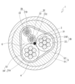
- FIG. 1 shows the configuration of a cable 1 with an abnormality sign detection function according to an embodiment of the present disclosure in a cross-sectional view cut perpendicularly to the axial direction.
- a cable 1 with an abnormality sign detection function includes a target electric wire 2 (2A to 2D), a detection wire 3, a tape layer 4, and a sheath 5.
- FIG. 2 shows a cross section of the sensing wire 3 .
- the target electric wire 2 is an electric wire that performs functions such as power supply, voltage application, communication, etc., required by the device or the like mounted with the cable 1, and is an electric wire that is to be detected for signs of damage in the cable 1.
- the number of target electric wires 2 is not particularly specified, and may be one or more.
- Each target wire 2 has a wire conductor 21 (21A to 21D) configured as a conductor wire, and a wire coating 22 that covers the outer periphery of the wire conductor 21 and is made of an insulating material.
- the cable 1 comprises four target wires 2A-2D. Two of these four are power supply lines 2A and 2B.
- the other two are communication lines 2C and 2D having conductor cross-sectional areas smaller than those of the power lines 2A and 2B, and are twisted together to form a twisted pair.
- the outer edge of the twisted pair is indicated by a dashed line.
- This type of composite cable including power supply lines 2A, 2B and communication lines 2C, 2D is used for electric brakes of automobiles and the like.
- the detection wire 3 is an electric wire that detects that the target electric wire 2 has a sign of breakage by causing its own breakage, as will be described later.
- the sensing wire 3 has a sensing wire conductor 31 configured as a conductor wire and a sensing wire covering 32 made of an insulating material and covering the outer periphery of the sensing wire conductor 31 .
- the number of detection lines 3 included in the cable 1 is not particularly limited, and may be one or more. Although the embodiment using only one detection wire 3 will be mainly described below, a plurality of detection wires 3 having different materials, wire diameters, numbers, etc. of the strands constituting the detection wire conductor 31 may be provided.
- the detection line coating 32 is preferably provided as a separate member from the detection line conductor 31 by covering the outer periphery of the detection line conductor 31 as a whole, which will be described later.
- the insulating coating layer 3c provided on the outer periphery of the wire 3b forming the outer peripheral portion of the sensing wire conductor 31 may also serve as the sensing wire coating 32. As shown in FIG.
- the bending life of the detection wire conductor 31 is shorter than that of the wire conductor 21 of the target wire 2 .
- the bending life of a conductor or wire indicates the period until breakage occurs when it is bent, and the number of bends until breakage occurs when bending is repeated at a predetermined angle. can be evaluated. A larger number of times of bending indicates a longer bending life (higher bending resistance).
- the detection wire conductor 31 includes a plurality of types of strands. is shorter than the wire conductor 21 of the target wire 2 .
- the bending life of the detection line conductor 31 is shorter than that of each of the wire conductors 21 of the plurality of target wires 2 .
- the power lines 2A, 2B and the communication lines 2C, 2D are included in the cable 1, it is common that the power lines 2A, 2B having a larger conductor cross-sectional area than the communication lines 2C, 2D have a shorter bending life. There is, and the bending life of the detection line conductor 31 is shorter than that of the power supply lines 2A and 2B.
- the following forms can be exemplified.
- the cross-sectional area of the conductor is the same, the greater the number of strands constituting the stranded conductor, the longer the flex life.
- the thinner the wire that constitutes the conductor the longer the flex life.
- the conductive material constituting the conductor exhibits high flex resistance as material properties, for example, when it has a large Young's modulus, a high rigidity modulus, and a high flexural strength, the flex life of the conductor becomes long.
- the shorter the twist pitch of the strands of the conductor the longer the flex life of the conductor.
- the sheath 5 is configured as an extruded insulator whose main component is a polymer material, surrounds the outer circumference of the tape layer 4, and constitutes the outermost circumference of the entire cable 1.
- the sheath 5 is tightly attached to the outer circumference of the tape layer 4 .
- it is preferable that the sheath 5 is in contact with the tape layer 4 over the entire circumference of the tape layer 4 without forming a gap between the sheath 5 and the tape layer 4 except for unavoidable gaps.
- the sheath 5 may be composed of a single layer or a plurality of layers. are also made of materials with excellent mechanical properties such as wear resistance.
- the tape layer 4 may be omitted, and the sheath 5 may be formed as an extruded body directly in close contact with the outer periphery of the wire group G.
- the sheath 5 is formed as an extruded body and is in close contact with the outer periphery of the wire group G via the tape layer 4 as appropriate.
- a sign of disconnection of the target electric wire 2 can be accurately detected by the detection wire 3 with sensitivity that does not depend on position or time.
- the detection line conductor 31 that constitutes the detection line 3 included in the cable 1 with an abnormality portent detection function will be described.
- the detection line conductor 31 is configured as an assembly of a plurality of strands, but not all of them are made of the same strand, but a plurality of strands of two types, a long-life strand 3a and a short-life strand 3b. contains.
- Each of the long-lived wire 3a and the short-lived wire 3b is individually configured as a wire in which an insulating coating layer 3c is formed on the outer periphery of single wires 3a1 and 3b1 made of a conductive material.
- the short-lived wire 3b has a shorter bending life of the single wire made of conductive material than the long-lived wire 3a.
- the flexing life of a single wire made of a conductive material that constitutes the wire may be simply referred to as the flexing life of the wire.
- a plurality of long-life strands 3a are assembled into one at the center to form a group.
- a plurality of short-lived wires 3b are arranged in layers on the outer circumference of the group of long-lived wires 3a. That is, the long-lived wires 3 a and the short-lived wires 3 b are arranged in layers and separated from each other. While there is an area where only the wires 3b are arranged, there is an area inside the sensing wire conductor 31 along the circumferential direction of the sensing wire conductor 31 where only the long-life strands 3a are arranged.
- short-lived wires 3b may be arranged in two or more layers.
- the entire assembly of the plurality of long-life strands 3a and the plurality of short-life strands 3b arranged in the predetermined arrangement is twisted.
- the long-lived wire 3a may be configured to have a wire diameter smaller than that of the short-lived wire 3b.
- the long-life strands 3a and the short-life strands 3b are different from each other at least in their constituent materials, and the long-life strands 3a are preferably made of a material exhibiting higher bending resistance.
- a copper alloy is used for the long-life wire 3a and copper (annealed copper) is used for the short-life wire 3b
- an aluminum alloy is used for the long-life wire 3a
- a form using an aluminum alloy can be preferably exemplified.
- the long-lived wire 3a and the short-lived wire 3b each have an insulating coating layer 3c. Therefore, the long-life wire 3a and the short-life wire 3b are insulated from each other, and the long-life wire 3a and the short-life wire 3b are insulated from each other.
- the specific type and thickness of the insulating coating layer 3c are not particularly limited, it is preferably composed of an enamel coating layer.
- the cable 1 includes a detection line conductor 31 having a shorter bending life than the electric wire conductor 21 of the target electric wire 2, in addition to the target electric wire 2 that performs a predetermined function in a device or the like. contains. If the cable 1 is repeatedly subjected to bending or vibration, the detection wire conductor 31 having a short bending life will break before the wire conductor 21 . The reason why the detection wire conductor 31 is broken is that the target wire 2 is also subjected to a load due to bending or vibration, and metal fatigue is accumulated in the wire conductor 21. If the load continues to be applied as it is, the target wire 2 This means that there is a possibility that the wire conductor 21 of the wire breakage may also occur.
- a break in the sense line conductor 31 can be detected by an electrical measurement, such as a characteristic impedance measurement.
- the breakage of the detection line conductor 31 means that the single wires 3a1 and 3b1 of the conductive material are broken in at least a part of the strands (the long-life strand 3a and the short-life strand 3b) that constitute the detection line conductor 31. refers to causing
- disconnection of the wire conductor 21 of the target wire 2 may be simply referred to as disconnection of the target wire 2 .
- an electric signal is input to the detection wire conductor 31, and the characteristic impedance (or There are methods of measuring other electrical parameters obtained by electrical measurements;
- an inspection signal containing an AC component is input to the entire sensing wire conductor 31 including the long-life wire 3a and the short-life wire 3b, with reference to the external ground potential.
- the response signal is detected by a reflection method or a transmission method, preferably a reflection method.
- the electrical signal is reflected at the break, resulting in a discontinuous change in the response signal. Therefore, when the measured characteristic impedance changes more than the reference value, it is determined that the detection line conductor 31 is broken and the wire conductor 21 of the target wire 2 is a sign of breakage. be able to.
- the characteristic impedance value usually increases. A change in the characteristic impedance also occurs due to damage to the detection line conductor 31 that does not lead to breakage of the wires 3a1 and 3b1.
- the time domain method or the frequency domain method is used to measure the characteristic impedance, it is possible to specify the position where the load is applied along the axial direction of the cable 1 and the detection line conductor 31 is broken.
- a pulse electric signal is input to the detection line conductor 31, and the time at which the characteristic impedance changes appears is converted into a position along the axial direction of the cable 1, thereby locating the breakage position. can know.
- the frequency domain method an electrical signal containing a plurality of frequency components is input to the detection line conductor 31, and the response signal is Fourier transformed to convert frequency information into position information on the cable 1.
- the characteristic impedance for the sensing line 3 it is preferable to measure the characteristic impedance for the sensing line 3 continuously or intermittently while the cable 1 is in use. Then, if a sign of disconnection occurs in the electric wire conductor 21 of the target electric wire 2, the sign of disconnection can be detected at an early stage and notified to the user of the device in which the cable 1 is mounted.
- the characteristic impedance of the detection line 3 may be measured at a predetermined time, such as a periodical inspection of equipment in which the cable 1 is arranged.
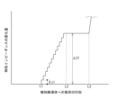
- the bending life of the short-lived wire 3b is shorter than that of the long-lived wire 3a. Therefore, when the detection wire conductor 31 is repeatedly subjected to a load due to bending or vibration of the cable 1, the short-lived wire 3b breaks earlier than the long-lived wire 3a. In this manner, the characteristic impedance of the detection wire conductor 31 changes stepwise due to the difference in breakage timing between the short-lived wire 3b and the long-lived wire 3a. That is, FIG. 3 shows the amount of change in the characteristic impedance with respect to the degree of load application to the detection line conductor 31 over time (for example, the number of times of bending).
- the short-life wire 3b is broken, and the characteristic impedance rises (after the load level L1).
- the amount of change in the characteristic impedance due to the breakage of all the short-lived strands 3b is indicated by ⁇ Z1.
- the long-life strand 3a also breaks.
- the characteristic impedance further increases (below load level L3).
- the breakage of the short-lived wire 3b and the breakage of the long-lived wire 3a occur because the cable 1 as a whole is subjected to cumulative load application due to repeated bending and the like. means that there is In other words, it means that the possibility of disconnection in the target electric wire 2 due to metal fatigue is increasing.
- the degree of urgency (How much load should be applied to actually break the wire) can be determined in two stages. Specifically, at the stage where only the change in characteristic impedance (change in ⁇ Z1) corresponding to the breakage of the short-lived wire 3b occurs, it can be determined that the target wire 2 is not yet likely to break. However, if a change in the characteristic impedance corresponding to the breakage of the long-life strand 3a occurs, it indicates that the target wire 2 is likely to break.
- the gradual change in the characteristic impedance of the detection line conductor 31 can detect the degree of urgency of the sign of disconnection of the target electric wire 2 in stages, so that the equipment in which the cable 1 is mounted can detect the urgency according to the degree of urgency. It is possible to take measures such as issuing an alarm.
- a plurality of target wires 2 with different flexing lives are included, such as the power lines 2A and 2B and the communication lines 2C and 2D of the cable 1
- disconnection of the target wires 2 with a short flexing life such as the power lines 2A and 2B is detected by the breakage of the short-lived wire 3b
- a sign of breakage of the target wires 2 having a long bending life such as the communication lines 2C and 2D is detected by the breakage of the long-life wire 3a.
- each of the short-lived wires 3b and the long-lived wires 3a does not have the insulating coating layer 3c and is electrically connected to each other, even if one of the short-lived wires 3b is broken, the neighboring The unbroken short-lived wire 3b or long-lived wire 3a comes into contact with the broken short-lived wire 3b and bridges the broken point, so that the broken short-lived wire 3b is electrically connected. continuity is interrupted (chattering; re-establishment of conduction). Then, the characteristic impedance of the detection line conductor 31 does not change. Alternatively, even if a change occurs, there may be a situation where the amount of change becomes small, or a situation where only a gradual change occurs.
- the short-lived wires 3b and the long-lived wires 3a are insulated from each other by the insulating coating layer 3c, so that when a certain short-lived wire 3b is broken, A state in which the short-lived wire 3b is insulated from the surrounding short-lived wire 3b and the long-lived wire 3a so that continuity of the short-lived wire 3b is interrupted at the break point is will remain stable. Then, the measured value of the characteristic impedance of the detection line conductor 31 is significantly and clearly affected by the breakage of the short-lived wire 3b.
- the characteristic impedance of the detection wire conductor 31 changes stepwise as shown in FIG. A clear change in , that is, a change in form in which the value suddenly fluctuates (usually rises) from a stable state, and then stabilizes again after the change.
- the representative value of the amount of change in the characteristic impedance corresponding to each short-life strand 3b is indicated as ⁇ z1.
- the size of the step is not necessarily constant, but small steps such as the amount of change ⁇ z1 are taken, Changes in the characteristic impedance accumulate, and the value of the characteristic impedance rises step by step. Then, when all the short-lived wires 3b are broken (load level L2), the amount of change in the characteristic impedance accumulated from the initial breakage of the short-lived wires 3b (load level L1) reaches ⁇ Z1.
- the degree of urgency of the sign of breakage in the target wire 2 can be determined. , and detection can be performed by distinguishing roughly into two stages. Further, by detecting in stages that the short-lived wire 3b is broken one by one, the sign of breakage in the target electric wire 2 can be further classified into finer stages. can be detected by As a result, it becomes easier to take various and appropriate countermeasures according to the degree of urgency of disconnection.
- each It is important to prevent chattering due to the short-lived wires 3b and the long-lived wires 3a individually having the insulating coating layers 3c.
- the short-lived wires 3b and the long-lived wires 3a are separated and arranged in concentric layers, and the short-lived wires 3b are positioned on the outer periphery of the entire detection wire conductor 31.
- the short-lived wire 3b greatly contributes to the phenomenon in which the short-lived wire 3b breaks earlier than the long-lived wire 3a, giving a distinct change in characteristic impedance one by one.
- the short-life wire 3b is configured as a wire having a shorter bending life than the long-life wire 3a. rupture in the Furthermore, even if the wires are the same, the wires placed on the outer side of the conductor are subjected to a larger load when the conductor is bent, and are more likely to break even with a small number of bends. Become. This is because, when the conductor is bent, the wire that can be bent with the smallest radius of curvature inside the bending shape is the wire arranged on the outermost side of the conductor.
- the short-lived wires 3b are arranged on the outer periphery of the group of the long-lived wires 3a. The difference in flexing life between the long-life wire 3a and the short-life wire 3b is amplified, and the short-life wire 3b tends to break with a smaller number of bends than the long-life wire 3a. .
- the two types of strands 3a and 3b are broken, and the short-lived strands 3b are first broken one by one in a stepwise manner, and then the long-lived strands 3a are broken. becomes difficult. Even if they occur in good order, the difference in the timing of breakage of the two types of strands 3a and 3b becomes small. Then, as shown in FIG. 3, a distinct stepwise change in characteristic impedance due to breakage of each short-lived wire 3b is less likely to occur.
- the region where the two types of wires 3a and 3b with different bending lives are arranged is divided into concentric layers, and the long-life wire 3a is arranged.
- the wires 3a and 3b break according to the bending life in an orderly and well-separated manner. That is, first, the short-lived wires 3b are broken one by one, and after (almost) all the short-lived wires 3b are broken, the long-lived wires 3a are broken at intervals. In this way, the breakage of the wires 3a and 3b proceeds in an orderly manner and in a well-separated manner, so that the change in the characteristic impedance corresponding to the breakage of each short-lived wire 3b is small. also become detectable as distinct step-like multi-step changes. As a result, it is possible to perform stepwise detection of a sign that the target electric wire 2 will be disconnected with high accuracy.
- the arrangement of the short-lived wire 3b outside the long-lived wire 3a means that the breakage of the wires 3a and 3b proceeds in distinct steps as described above. Also from the viewpoint of the detection sensitivity of the breakage of the short-lived wire 3b, it contributes to the improvement of the accuracy of stepwise detection of the signs of breakage.
- an alternating current especially a high-frequency alternating current such as 1 MHz or higher, such as characteristic impedance measurement
- the skin effect causes the sensing line conductor 31 The current flows in a concentrated manner on the surface of the .
- the long-lived wires 3a and the short-lived wires 3b are each covered with the insulating coating layer 3c, and the short-lived wires 3b are arranged around the group of the long-lived wires 3a.
- the disconnection of each short-life strand 3b due to the application of a load such as bending can be clearly detected as a change in the characteristic impedance of the detection wire conductor 31 .
- the degree of urgency of the sign of disconnection in the target electric wire 2 can be subdivided into multiple stages and detected with high accuracy. After the short-lived wires 3b are entirely broken, the long-lived wires 3a are broken.
- a plurality of target wires 2 with different flexing lives are included, such as the power lines 2A and 2B and the communication lines 2C and 2D of the cable 1, disconnection in the target wires 2 with a short flexing life such as the power lines 2A and 2B
- the signs of this are detected by classifying the degree of gradual breakage of the short-life wire 3b, and the sign of breakage of the target wires 2 with a long bending life, such as the communication lines 2C and 2D, is detected by the long-life wire 3a. It is conceivable to configure so as to detect the breakage of the wire.
- the short-lived wire 3b is targeted, and stepwise detection of breakage in units of one wire has been described.
- gradual breakage may progress in the same manner as in the short-lived wire 3b.
- the long-life strands 3a are also covered with the insulating coating layer 3c one by one, their gradual breakage can be detected by the step-like change in the characteristic impedance in the same manner as the breakage of the short-life strands 3b. there is a possibility.
- the detection wire conductor 31 is composed of two types of wires, the short-life wire 3b and the long-life wire 3a.
- the wires may be arranged in multiple layers so that the flex life becomes shorter from the inner layer side to the outer layer side. Then, it becomes possible to classify and detect signs of breakage of the target electric wire 2 in a wider range according to the degree of urgency.
- the wire abnormality sign detection system includes the cable with abnormality sign detection function 1 according to the embodiment of the present disclosure described above, and a measurement unit.
- the measurement unit is a measuring device that measures the characteristic impedance of the detection line conductor 31 of the detection line 3 included in the cable 1 with an abnormality portent detection function.
- an insulating coating S2 is applied to the outer periphery of a detection wire conductor in which 37 enameled wires with a wire diameter of 0.1 mm are bundled as a strand S1 so that the outer diameter is 1.0 mm.
- a detection line with The length of the detection line was 1 m.
- the conductor was made of copper, the conductor diameter was ⁇ 0.08 mm, and the enamel coating thickness was 0.01 mm.
- a region was formed in which a portion of the wire was cut off over a length of 10 mm in the central portion in the longitudinal direction, simulating the breakage of the wire.
- a circuit analysis simulation based on electromagnetic field analysis was performed for the detection lines in each state from CUT0 to CUT36, and the characteristic impedance was estimated.
- the electromagnetic field analysis software "Ansys HFSS" was used for the simulation.
- the same insulated wire as the above-mentioned detection wire (state of CUT0) in which the wire is not broken was provided adjacent to the lower side of the detection wire, and the potential of the insulated wire was taken as the ground potential.
- the terminating resistance was set to 50 ⁇ .
- FIG. 5A shows the characteristic impedance obtained by simulation for each state of CUT0 to CUT36 in the frequency range from 0 to 100 MHz. Further, FIG. 5B shows changes in the characteristic impedance value at a frequency of 50 MHz, read from the results of FIG. 5A, for regions where the number of wire breaks is small. The horizontal axis indicates the number of broken wires, and the vertical axis indicates the characteristic impedance.
- FIG. 5A As the number of broken strands increases, the characteristic impedance value increases at the top of the peak and in the vicinity thereof.
- FIG. 5B more clearly shows the stepwise increase in characteristic impedance as the number of broken strands increases. In other words, it can be seen that when the strands are broken one by one or several strands at a time, the breakage of the strands causes a stepwise rise in the characteristic impedance.
- the long-life strand is arranged inside the detection wire conductor, and the outer circumference of the group of long-life strands.
- the effect of the arrangement that the wires located on the outer peripheral side of the conductor are more likely to break. is likely to occur in order from the outer peripheral side of the detection line conductor.
Landscapes
- Physics & Mathematics (AREA)
- General Physics & Mathematics (AREA)
- Insulated Conductors (AREA)
Priority Applications (3)
| Application Number | Priority Date | Filing Date | Title |
|---|---|---|---|
| JP2023576966A JP7677466B2 (ja) | 2022-01-28 | 2023-01-26 | 異常予兆検知機能付ケーブルおよび電線異常予兆検知システム |
| CN202380017699.XA CN118575233A (zh) | 2022-01-28 | 2023-01-26 | 带有异常预兆检测功能的电缆和电线异常预兆检测系统 |
| US18/727,203 US20250095880A1 (en) | 2022-01-28 | 2023-01-26 | Cable with abnormality sign detection function and wire abnormality sign detection system |
Applications Claiming Priority (2)
| Application Number | Priority Date | Filing Date | Title |
|---|---|---|---|
| JP2022-011409 | 2022-01-28 | ||
| JP2022011409 | 2022-01-28 |
Publications (1)
| Publication Number | Publication Date |
|---|---|
| WO2023145803A1 true WO2023145803A1 (ja) | 2023-08-03 |
Family
ID=87471491
Family Applications (1)
| Application Number | Title | Priority Date | Filing Date |
|---|---|---|---|
| PCT/JP2023/002386 Ceased WO2023145803A1 (ja) | 2022-01-28 | 2023-01-26 | 異常予兆検知機能付ケーブルおよび電線異常予兆検知システム |
Country Status (4)
| Country | Link |
|---|---|
| US (1) | US20250095880A1 (https=) |
| JP (1) | JP7677466B2 (https=) |
| CN (1) | CN118575233A (https=) |
| WO (1) | WO2023145803A1 (https=) |
Citations (3)
| Publication number | Priority date | Publication date | Assignee | Title |
|---|---|---|---|---|
| JP2006032060A (ja) * | 2004-07-14 | 2006-02-02 | Hitachi Cable Ltd | 断線検知機能付ケーブル |
| JP2007299608A (ja) * | 2006-04-28 | 2007-11-15 | Hitachi Cable Ltd | 断線検知機能付きケーブル |
| JP2013182716A (ja) * | 2012-02-29 | 2013-09-12 | Hitachi Cable Ltd | 断線検知機能付ケーブル |
Family Cites Families (1)
| Publication number | Priority date | Publication date | Assignee | Title |
|---|---|---|---|---|
| JP4760521B2 (ja) | 2006-05-12 | 2011-08-31 | 日立電線株式会社 | 電気ケーブルの断線検知装置および断線検知方法 |
-
2023
- 2023-01-26 US US18/727,203 patent/US20250095880A1/en active Pending
- 2023-01-26 CN CN202380017699.XA patent/CN118575233A/zh active Pending
- 2023-01-26 WO PCT/JP2023/002386 patent/WO2023145803A1/ja not_active Ceased
- 2023-01-26 JP JP2023576966A patent/JP7677466B2/ja active Active
Patent Citations (3)
| Publication number | Priority date | Publication date | Assignee | Title |
|---|---|---|---|---|
| JP2006032060A (ja) * | 2004-07-14 | 2006-02-02 | Hitachi Cable Ltd | 断線検知機能付ケーブル |
| JP2007299608A (ja) * | 2006-04-28 | 2007-11-15 | Hitachi Cable Ltd | 断線検知機能付きケーブル |
| JP2013182716A (ja) * | 2012-02-29 | 2013-09-12 | Hitachi Cable Ltd | 断線検知機能付ケーブル |
Also Published As
| Publication number | Publication date |
|---|---|
| JP7677466B2 (ja) | 2025-05-15 |
| US20250095880A1 (en) | 2025-03-20 |
| CN118575233A (zh) | 2024-08-30 |
| JPWO2023145803A1 (https=) | 2023-08-03 |
Similar Documents
| Publication | Publication Date | Title |
|---|---|---|
| JP7740473B2 (ja) | 異常予兆検知機能付ケーブル | |
| US9488688B2 (en) | Electric cable wear control system | |
| US7145345B2 (en) | Current transformers for partial discharge detection on aircraft cables and wires | |
| JP2022179553A5 (ja) | 電線異常予兆検知装置 | |
| CN101456509A (zh) | 电梯钢丝绳检查装置 | |
| CN115398261A (zh) | 电线检查系统、电线检查方法及电线 | |
| JP2013182716A (ja) | 断線検知機能付ケーブル | |
| JP2025126334A (ja) | 異常予兆検知機能付ケーブル | |
| US20250003818A1 (en) | Pressure detection system for electric wire | |
| JP4967442B2 (ja) | 断線検知機能付きケーブル | |
| WO2023145803A1 (ja) | 異常予兆検知機能付ケーブルおよび電線異常予兆検知システム | |
| US20160109394A1 (en) | Overlayer intended to cover an object, in particular a cable, in order to detect and/or locate a defect on the surface of same | |
| JP4760521B2 (ja) | 電気ケーブルの断線検知装置および断線検知方法 | |
| JP2006032060A (ja) | 断線検知機能付ケーブル | |
| JP7732513B2 (ja) | 多芯ケーブル、断線検知装置 | |
| JP7803348B2 (ja) | 多芯ケーブル、断線検知装置 | |
| JPH0295273A (ja) | 素線数を多くした複合撚線を有する電線ケーブルの導体断線検知方法 | |
| US20250102598A1 (en) | Disconnection detection device | |
| EP4390370A1 (en) | System for detecting a degradation in a protective coating and associated method | |
| JPWO2023145803A5 (https=) | ||
| WO2024132309A1 (en) | System for detecting a degradation in a protective coating and associated method |
Legal Events
| Date | Code | Title | Description |
|---|---|---|---|
| 121 | Ep: the epo has been informed by wipo that ep was designated in this application |
Ref document number: 23747013 Country of ref document: EP Kind code of ref document: A1 |
|
| WWE | Wipo information: entry into national phase |
Ref document number: 18727203 Country of ref document: US |
|
| ENP | Entry into the national phase |
Ref document number: 2023576966 Country of ref document: JP Kind code of ref document: A |
|
| WWE | Wipo information: entry into national phase |
Ref document number: 202380017699.X Country of ref document: CN |
|
| NENP | Non-entry into the national phase |
Ref country code: DE |
|
| 122 | Ep: pct application non-entry in european phase |
Ref document number: 23747013 Country of ref document: EP Kind code of ref document: A1 |
|
| WWP | Wipo information: published in national office |
Ref document number: 18727203 Country of ref document: US |