WO2023145638A1 - 眼科装置及び眼科プログラム - Google Patents
眼科装置及び眼科プログラム Download PDFInfo
- Publication number
- WO2023145638A1 WO2023145638A1 PCT/JP2023/001678 JP2023001678W WO2023145638A1 WO 2023145638 A1 WO2023145638 A1 WO 2023145638A1 JP 2023001678 W JP2023001678 W JP 2023001678W WO 2023145638 A1 WO2023145638 A1 WO 2023145638A1
- Authority
- WO
- WIPO (PCT)
- Prior art keywords
- eye
- measurement
- face
- image
- position information
- Prior art date
- Legal status (The legal status is an assumption and is not a legal conclusion. Google has not performed a legal analysis and makes no representation as to the accuracy of the status listed.)
- Ceased
Links
Images




Classifications
-
- A—HUMAN NECESSITIES
- A61—MEDICAL OR VETERINARY SCIENCE; HYGIENE
- A61B—DIAGNOSIS; SURGERY; IDENTIFICATION
- A61B3/00—Apparatus for testing the eyes; Instruments for examining the eyes
- A61B3/10—Objective types, i.e. instruments for examining the eyes independent of the patients' perceptions or reactions
-
- A—HUMAN NECESSITIES
- A61—MEDICAL OR VETERINARY SCIENCE; HYGIENE
- A61B—DIAGNOSIS; SURGERY; IDENTIFICATION
- A61B3/00—Apparatus for testing the eyes; Instruments for examining the eyes
- A61B3/10—Objective types, i.e. instruments for examining the eyes independent of the patients' perceptions or reactions
- A61B3/103—Objective types, i.e. instruments for examining the eyes independent of the patients' perceptions or reactions for determining refraction, e.g. refractometers, skiascopes
-
- A—HUMAN NECESSITIES
- A61—MEDICAL OR VETERINARY SCIENCE; HYGIENE
- A61B—DIAGNOSIS; SURGERY; IDENTIFICATION
- A61B3/00—Apparatus for testing the eyes; Instruments for examining the eyes
- A61B3/10—Objective types, i.e. instruments for examining the eyes independent of the patients' perceptions or reactions
- A61B3/113—Objective types, i.e. instruments for examining the eyes independent of the patients' perceptions or reactions for determining or recording eye movement
Definitions
- the present disclosure relates to an ophthalmic device and an ophthalmic program for objectively measuring optical characteristics of an eye to be examined.
- an ophthalmologic apparatus for example, there is known one that measures the optical characteristics of a subject's eye by projecting a measurement light flux onto the fundus of the subject's eye and receiving the reflected light flux of the subject's eye (see Patent Document 1).
- the technical problem of the present disclosure is to provide an ophthalmologic apparatus and an ophthalmologic program capable of acquiring eye position information of an eye to be examined.
- An ophthalmologic apparatus is an ophthalmologic apparatus that objectively measures optical characteristics of an eye to be examined, comprising: face imaging means for imaging a face image of a subject; eye position information acquisition means for acquiring eye position information of the eye to be inspected based on the face image thus obtained.
- An ophthalmologic program is an ophthalmologic program used in an ophthalmologic apparatus that objectively measures optical characteristics of an eye to be examined, and is executed by a processor of the ophthalmologic apparatus to provide a subject with and an eye position information acquiring step of acquiring eye position information of the subject's eye based on the face image captured in the face capturing step. characterized by
- FIG. 1 is an external view of an eye refractive power measuring device;
- FIG. 1 is a schematic configuration diagram of an optical system and a control system of an eye refractive power measuring device;
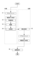
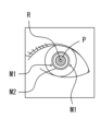
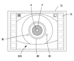
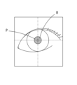
- FIG. It is a flowchart figure which shows the control action of an ophthalmologic apparatus. It is the whole image of a subject's face image. It is an enlarged view of the right eye of the face image. It is an enlarged view of the left eye of the face image. It is an example of an anterior segment image of the right eye. This is an example of an upright eye. This is an example of oblique eyes.
- the ophthalmologic apparatus of this embodiment objectively measures the optical characteristics of the subject's eye.
- the optical characteristics of the eye to be examined include ocular refractive power (e.g., spherical power, cylindrical power, astigmatism axis angle, etc.), binocular vision function (e.g., oblique amount, stereoscopic vision function, etc.), contrast sensitivity, and axial length. , corneal shape, and the like.
- the ophthalmologic apparatus of the present embodiment may include face imaging means.
- the face photographing means photographs a face image of the subject.
- the face photographing means may photograph a face image including at least one of the right eye and the left eye among the eyes to be examined. That is, an image of a part of the face including either one of the right eye and the left eye may be captured, or an image of the entire face including both the right eye and the left eye may be captured.
- the configuration is such that a face image can be captured at an angle of view that allows capturing of both the right eye and the left eye.
- the face photographing means may include a face illumination optical system (for example, face illumination optical system 600) as a part of the face photographing means.
- the face illumination optical system may illuminate the subject's face by emitting an illumination light beam toward the subject's face.
- the face illumination optical system may have at least a light source.
- the face photographing means may include a face photographing optical system (for example, the face photographing optical system 700) as a part of the face photographing means.
- the face imaging optical system captures an image of the subject's face by receiving reflected light beams from the subject's face. For example, a reflected light flux of natural light may be received to photograph a face. Further, for example, when a face illumination optical system is provided, the face may be photographed by receiving a reflected light flux of the illumination light flux emitted from the light source of the face illumination optical system.
- the face imaging optical system may have at least an imaging element.
- the optical axis of the face photographing optical system may be arranged at a position deviated in either the left or right direction from the optical axis of the measurement optical system, which will be described later.
- the optical axis of the face photographing optical system in order to measure the subject's eye, when the optical axis of the measurement optical system is aligned with the subject's eye, the optical axis of the face photographing optical system can be arranged near the center of the face. Therefore, it becomes easier to photograph a face image including both the right eye and the left eye.
- the amount of deviation between the optical axis of the face photographing optical system and the optical axis of the measuring optical system may be an amount considering the average interpupillary distance of the human eye (64 mm), but of course the amount may be different. good too.
- the fixation target presenting means which will be described later, is presenting the fixation target to the measurement eye, which is one of the right eye and the left eye
- the face photographing means is the non-measurement eye, which is the other of the right eye and the left eye.
- a face image including non-measurement eyes different from the measurement eyes may be captured. That is, while the fixation target is presented to the eye to be measured, a face image including at least the non-measurement eye may be captured. For example, this makes it possible to efficiently acquire optical characteristics and eye position information without the need to separately provide time for photographing a face image for eye position measurement of the subject's eye.
- the face photographing means may photograph the face image including the non-measurement eye while the measurement eye is fixating the fixation target. good.
- the state in which the measurement eye is fixated on the fixation target may be a state in which the measurement eye is focused on the fixation target.
- the fixation target may be clearly observed by the measurement eye.
- the fixation target may be vaguely observed by the measuring eye.
- the face photographing means may photograph the face image including the non-measurement eye while the fixation target presenting means is presenting the fixation target to the measurement eye while adding fog to the measurement eye. .
- the state in which the fog is added to the measurement eye is a state in which the fixation target is vaguely observed by the measurement eye.
- a state in which the measurement eye clearly or vaguely observes the fixation target is a state in which only the measurement eye (that is, one eye) visually recognizes the fixation target, and the eye position of the non-measurement eye tends to shift.
- the face photographing means may be part of the alignment means.
- the alignment means photographs the subject's eye and adjusts the positional relationship between the subject's eye and the ophthalmologic apparatus (for example, the positional relationship between the subject's eye and measuring means described later). That is, a face image may be photographed by the face photographing means, and relative positioning of the measuring means with respect to the subject's eye may be performed based on the face image.
- photographing dedicated to eye position measurement may be used.
- the device can be easily configured without providing any means.
- the ophthalmologic apparatus of this embodiment may include eye position information acquisition means (for example, the control unit 70).
- the eye position information acquiring means acquires the eye position information of the subject's eye based on the face image photographed by the face photographing means.
- eye position information may include information about strabismus (eg, at least one of the presence or absence of strabismus, the direction of deviation of strabismus, the amount of deviation of strabismus, etc.).
- the eye position information may include information about oblique (for example, at least one of presence/absence of oblique, deviation direction of oblique, amount of deviation of oblique, etc.).
- eye position information may include strabismus information and oblique information.
- the eye position information acquisition means may acquire only the eye position information of one of the right eye and the left eye of the subject's eye based on the face image.
- the eye position information acquiring means may acquire the eye position information of the other eye based on the eye position information of one eye based on the face image.
- eye position information for one eye may be used to obtain eye position information for the other eye.
- the eye position information acquisition means may acquire the eye position information of both eyes based on the face image, out of the right eye and the left eye of the subject's eye.
- the eye position information acquiring means determines the eye position of at least the non-measurement eye based on the face image including the non-measurement eye captured by the face imaging means while the fixation target presentation means is presenting the fixation target to the measurement eye. information may be obtained. In other words, at least the eye position information of the non-measurement eye may be acquired based on the image of the non-measurement eye in the face image including the non-measurement eye. In this case, the eye position information acquisition means may acquire at least the eye position information of the non-measuring eye based on the face image in which the eye to be measured fixates on the fixation target.
- the sight line of the measurement eye is directed in a predetermined reference direction by fixating the measurement eye on the fixation target. Eye position information is acquired. In addition, variation due to changes in eye position of non-measuring eyes can be suppressed.
- the eye position information acquiring means may include: At least the eye position information of the non-measuring eye may be acquired based on the face image with fog added to the face image. For example, if the time to add fog to the eye to be measured is set to be long enough to release the adjustment, the time required to capture the face image is less likely to run out, resulting in more efficient acquisition of eye position information. be done.
- the eye position information obtaining means obtains the corneal bright spot image included in the face image and the pupil based on the calibration data based on the positional relationship between the corneal bright spot image formed on the eye to be examined and the pupil of the eye to be examined. Eye position information may be obtained based on the positional relationship. In this case, the eye position information can be easily acquired simply by photographing one face image.
- the eye position information acquiring means utilizes the presence or absence of a change in the positional relationship between the corneal bright point image and the pupil in the calibration data and the positional relationship between the corneal bright point image and the pupil in the face image to determine whether the strabismus or oblique
- the presence or absence of the position may be detected.
- a threshold value may be set for such a change in positional relationship, and the presence or absence of strabismus or oblique posture may be detected depending on whether the change is less than or greater than the threshold value.
- the eye position information acquisition means determines, from the direction and amount of change in the positional relationship between the corneal luminescent point image and the pupil in the calibration data and the positional relationship between the corneal luminescent point image and the pupil in the face image, squint or squint. At least one of the deviation direction and the amount of oblique deviation may be detected.
- the calibration data may be data indicating the positional relationship between the corneal bright spot image and the pupil when the subject's eye is upright.
- the eye position information acquiring means may acquire the eye position information based on an anterior segment image captured by the anterior segment capturing means described later and a face image captured by the face image capturing means. In this case, eye position information can be easily obtained by capturing an anterior segment image and a face image.
- the eye position information acquiring means utilizes the presence or absence of a change in the positional relationship between the corneal bright point image and the pupil in the anterior segment image and the positional relationship between the corneal bright point image and the pupil in the face image to determine strabismus or squint.
- the presence or absence of oblique position may be detected.
- the presence or absence of strabismus or oblique posture may be detected depending on whether such a change in positional relationship is less than or greater than a threshold.
- the eye position information acquisition means determines the positional relationship between the corneal bright point image and the pupil in the anterior segment image and the positional relationship between the corneal bright point image and the pupil in the face image from the direction and amount of change. At least one of the deviation direction and the amount of the oblique deviation may be detected.
- the anterior segment image and the face image may be images including the same eye.
- the anterior segment image may be an anterior segment image of the right eye in a state in which the right eye is the measurement eye and the left eye is the non-measurement eye. That is, it may be an anterior segment image of the right eye in a state in which the right eye fixates on a fixation target or in a state in which fog is added to the right eye.
- the face image may be a face image including at least the right eye in a state where the left eye is the eye to be measured and the right eye is the non-measurement eye. That is, it may be a face image including the right eye in a state where the left eye is fixated on the fixation target or in a state where fog is added to the left eye.
- the ophthalmologic apparatus of this embodiment may comprise a fixation target presenting means.
- the fixation target presenting means presents the fixation target to the eye to be examined.
- the fixation target presenting means may include a fixation target presenting optical system (for example, the fixation target optical system 300) as a part of the fixation target presenting means.
- the fixation target presenting optical system may present the fixation target to the subject's eye by emitting a target light flux toward the subject's eye.
- the optotype light flux may be directly guided to the eye to be examined, or may be guided to the eye to be examined via at least one optical member (eg, a lens, a mirror, etc.).
- the fixation target presenting optical system may be configured to use a light source and a fixation target plate, a light source, a DMD (Digital Micromirror Device), a display, and the like as a fixation target.
- DMD Digital Micromirror Device
- the ophthalmologic apparatus of the present embodiment may include measuring means.
- the measurement unit measures the optical characteristics of the eye by projecting the measurement light onto the eye and receiving the reflected light from the eye.
- the measuring means may measure the optical characteristics of the eye by projecting the measurement light beam onto the cornea of the eye to be inspected and receiving the reflected light beam of the measurement light beam reflected by the cornea.
- the measurement unit may measure the optical characteristics of the eye by projecting the measurement light flux onto the fundus of the subject's eye and receiving the reflected light flux of the measurement light flux reflected by the fundus.
- the measurement means may be provided with a measurement optical system as part of the measurement means.
- the measurement optical system may have a light projecting optical system that projects the measurement light flux onto the cornea of the subject's eye, and a light reception optical system that receives the reflected light flux of the measurement light flux reflected by the cornea.
- the measurement optical system (for example, measurement optical system 200) includes a projection optical system (for example, projection optical system 210) that projects the measurement light flux onto the fundus of the subject's eye, and a reflection light flux of the measurement light flux reflected by the fundus. and a light-receiving optical system (for example, the light-receiving optical system 220) that receives the .
- the measurement means may measure the measurement eye, which is one of the right eye and the left eye, among the eyes to be examined.
- the optical characteristics of the right eye may be measured with the right eye as the measurement eye and the left eye as the non-measurement eye.
- the optical characteristics of the left eye may be measured by using the left eye as the measurement eye and the right eye as the non-measurement eye.
- the ophthalmologic apparatus of this embodiment may include an anterior segment imaging means.
- the anterior segment imaging means captures an anterior segment image of the subject's eye.
- the anterior segment imaging means may capture an anterior segment image of either the right eye or the left eye. Further, the anterior segment imaging means may capture an anterior segment image of the eye to be measured in a state in which the eye to be measured fixates on the fixation target.
- the anterior segment imaging means may include an anterior segment imaging optical system (for example, the observation optical system 500) as a part of the anterior segment imaging means.
- the anterior segment imaging optical system captures an image of a face by receiving reflected light beams from the anterior segment of the subject's eye.
- the anterior eye imaging optical system may have at least an imaging element.
- terminal control software program
- program program
- a control device for example, CPU, etc.
- an eye refractive power measuring apparatus is taken as an example of an ophthalmologic apparatus, and the left-right direction of the eye refractive power measuring apparatus is indicated as the X direction, the vertical direction as the Y direction, and the front-back direction as the Z direction.
- FIG. 1 is an external view of an eye refractive power measuring device 1.
- the eye refractive power measurement apparatus 1 includes a base 2, a face support section 3, a drive section 4, a display section 75, an operation section 76, a measurement section 100, and the like.
- the face support part 3 is fixed to the base 2 and supports the subject's face.
- the drive unit 4 drives the measurement unit 100 in the XYZ directions with respect to the base 2 .
- the display unit 75 displays various types of information (for example, the face image of the subject, the anterior segment image of the subject's eye, the measurement results of the subject's eye, etc.).
- the operation unit 76 performs various settings.
- a display unit 75 with a touch panel also serves as the operation unit 76 .
- the measurement unit 100 accommodates an optical system, which will be described later.
- FIG. 2 is a schematic configuration diagram of the optical system and control system of the eye refractive power measuring apparatus 1.
- the measurement unit 100 includes a measurement optical system 200, a fixation target optical system 300, an index projection optical system 400, an observation optical system 500, a face illumination optical system 600, a face photographing optical system 700, and the like.
- the measurement optical system 200 objectively measures the eye refractive power of the subject's eye E (for example, spherical power, cylindrical power, astigmatism axis angle, etc.).
- the fixation target optical system 300 presents the eye E to be examined with a fixation target.
- the index projection optical system 400 projects an alignment index onto the eye E to be examined.
- the observation optical system 500 images the anterior segment of the eye E to be examined.
- a face illumination optical system 600 illuminates the subject's face.
- a face photographing optical system 700 photographs the subject's face.
- a beam splitter 230 is arranged in front of the eye E to be examined. The beam splitter 230 guides the measurement light flux from the fixation target optical system 300 to the eye E to be examined. The beam splitter 230 also guides the reflected light flux from the anterior segment of the eye E to be examined to the observation optical system 500 .
- the measurement optical system 200 has a light projecting optical system 210 and a light receiving optical system 220 in the transmission direction of the beam splitter 230 .
- the projection optical system 210 includes a light source 211, a relay lens 212, a hole mirror 213, a prism 214, an objective lens 216, and the like.
- the light source 211 is in an optically conjugate positional relationship with the fundus.
- the aperture of the hole mirror 213 is in an optically conjugate positional relationship with the pupil.
- the prism 214 is arranged at a position out of optical conjugate with the pupil, and decenters the light beam passing through the prism 214 with respect to the optical axis N1.
- the prism 214 is rotationally driven around the optical axis N1 by the driving section 215 .
- a plane-parallel plate may be obliquely arranged on the optical axis N1.
- the light source 211 desirably emits light in the infrared region that is less likely to be perceived as glare by the subject.
- the light source 211 may be used as an illumination light source for photographing a retroillumination image of the eye E to be examined. That is, the inside of the pupil of the subject's eye E may be illuminated by the fundus reflected light of the luminous flux (illumination light) emitted from the light source 211 .
- the light receiving optical system 220 includes an objective lens 216, a prism 214, a hall mirror 213, a relay lens 221, a total reflection mirror 222, a light receiving diaphragm 223, a collimator lens 224, a ring lens 225, an imaging device 226, and the like.
- the objective lens 216 , the prism 214 and the hole mirror 213 are shared with the light projecting optical system 210 .
- the light receiving diaphragm 223 is in a positional relationship optically conjugate with the fundus.
- the ring lens 225 is in an optically conjugate positional relationship with the pupil.
- the imaging device 226 is in a positional relationship optically conjugate with the fundus.
- the measurement light flux emitted from the light source 211 passes through the relay lens 212, the hole mirror 213, the prism 214, the objective lens 216, and the beam splitter 230, and forms a spot light flux on the fundus. projected.
- a point light source image is formed on the fundus.
- the prism 214 is rotated around the optical axis N1, and the pupil projected image (projected light flux on the pupil) at the aperture of the hole mirror 213 is eccentrically rotated at high speed.
- the reflected light flux which is the measurement light flux reflected by the fundus, is reflected by the hole mirror 213 via the beam splitter 230 , the objective lens 216 and the prism 214 .
- the reflected light beam further passes through the relay lens 221 and is reflected by the total reflection mirror 222, condensed at the position of the light receiving aperture 223, and picked up as a ring image by the collimator lens 224 and the ring lens 225. It is imaged onto element 226 .
- An output signal from the imaging element 226 is input to the control section 70, and the eye refractive power is calculated.
- the measurement optical system 200 is an optical system having a light projecting optical system that projects the measurement light flux onto the fundus of the subject's eye E and a light reception optical system that receives the reflected light flux of the measurement light flux reflected by the fundus.
- the measurement optical system 200 may be an optical system that projects a spot index onto the fundus of the eye and uses a Shack-Hartmann sensor to detect the reflected light flux of the spot index on the fundus of the eye.
- the measurement optical system 200 may be a phase-difference optical system that projects a slit onto the eye E to be examined.
- the fixation target optical system 300 has a light source 301 , a fixation target plate 302 , a projection lens 303 , a total reflection mirror 304 , a half mirror 305 , an objective lens 306 , etc. in the reflection direction of the beam splitter 230 .
- a fixation target is presented to the subject's eye E by illuminating the fixation target plate 302 with the light source 301 .
- the fixation target plate 302 is used when the subject's eye E is fixed and its eye refractive power is measured.
- the drive unit 307 can move the presentation position of the fixation target with respect to the eye E by moving the fixation target plate 302 in the direction of the optical axis N2. Further, the drive unit 307 can fog the eye E by moving the light source 301 and the fixation target plate 302 in the direction of the optical axis N2.
- the driving unit 307 may change the presentation position of the fixation target by moving the projection lens 303 with respect to the fixation target plate 302 in the direction of the optical axis N2. Therefore, the driving unit 307 may add fog to the subject's eye E by moving the projection lens 303 with respect to the fixation target plate 302 in the direction of the optical axis N2.
- the index projection optical system 400 includes a first index projection optical system and a second index projection optical system.
- the first index projection optical system projects an infinite alignment index onto the cornea of the eye E to be examined.
- the second index projection optical system projects a finite alignment index onto the cornea of the eye E to be examined.
- the first target projection optical system has point light sources 401a and 401b, collimator lenses 402a and 402b, and the like.
- the point light sources 401a and 401b emit near-infrared light.
- the collimator lenses 402a and 402b collimate the luminous flux emitted by the point light source into a parallel luminous flux (substantially parallel luminous flux).
- a plurality of these point light sources and collimator lenses are arranged on a concentric circle with respect to the optical axis N1 at intervals of 45 degrees and symmetrical with respect to a vertical plane passing through the optical axis N1. be.
- the second target projection optical system has point light sources 403a and 403b.
- the point light sources 403a and 403b emit near-infrared light.
- a plurality of these point light sources are arranged so as to have a narrower angle than the point light sources of the first target projection optical system and to be bilaterally symmetric across a vertical plane passing through the optical axis.
- the second target projection optical system can also be used as an anterior segment illumination for illuminating the anterior segment of the eye E to be inspected, an index for measuring the shape of the cornea of the eye E to be inspected, and the like.
- the index projection optical system 400 may be configured to project at least one of a point-like index, a ring-like index (so-called Meyer ring, etc.), a line-like index, and the like.
- the observation optical system 500 has an objective lens 306 , a half mirror 305 , an imaging lens 501 , an imaging element 502 , etc. in the reflection direction of the beam splitter 230 .
- the imaging device 502 is in a positional relationship optically conjugate with the anterior segment of the subject's eye E, and receives reflected light beams from the anterior segment.
- an anterior segment image of the subject's eye E (a front image of the anterior segment) is captured.
- a transillumination image which is a type of anterior segment image, may be captured.
- An output signal from the imaging element 502 is input to the control section 70 and the display section 75 .
- the observation optical system 500 also serves as an optical system for detecting an alignment index image formed on the cornea of the subject's eye E, and the controller 70 detects the position of the alignment index image.
- the face illumination optical system 600 includes an illumination light source 601 and the like.
- the illumination light source 601 may be a light source with low directivity.
- the illumination light source 601 may be a light source that emits infrared light.
- the face illumination optical system 600 can be used not only as a face illumination for illuminating the subject's face, but also as an index for measuring the eye position of the eye E to be examined. That is, the face illumination optical system 600 projects the index for eye position measurement onto the cornea of the eye E to be examined.
- the face imaging optical system 700 includes an imaging lens 701, an imaging element 702, and the like.
- the imaging element 702 receives the reflected light flux from the face. As a result, a face image including at least one of the left eye and the right eye of the subject's eye E is captured.
- An output signal from the imaging element 702 is input to the control section 70 and the display section 75 .
- the face photographing optical system 700 also serves as an optical system for detecting the index image for eye position measurement formed on the cornea of the subject's eye E, and the control unit 70 detects the position of the index image for eye position measurement.
- the face photographing optical system 700 includes a wide-angle lens as the imaging lens 701, so that the subject's face can be photographed with a wide angle of view.
- the angle of view may be 87° or more. This makes it easier for the subject's eyes to be included in the face image.
- a visible light cut filter may be arranged in the optical path of the face imaging optical system 700 . This limits visible light noise when photographing the subject's face.
- the reflected infrared light from the face is detected by the imaging element 702, but in this case, noise light due to the infrared light may enter. Therefore, the gain or the like of the image sensor 702 may be adjusted to reduce the influence of infrared light noise.
- the control unit 70 includes a CPU (processor), RAM, ROM, and the like.
- the CPU controls driving of each part in the eye refractive power measuring device 1 .
- the RAM temporarily stores various information.
- Various programs executed by the CPU are stored in the ROM.
- the controller 70 may be configured by a plurality of controllers (that is, a plurality of processors).
- the control unit 70 is electrically connected to the drive unit 4, the display unit 75 (operation unit 76), the nonvolatile memory 72 (hereinafter referred to as the memory 72), and the like.
- each light source, each imaging element, each drive section, and the like provided in the measurement section 100 are electrically connected to the control section 70 .
- the memory 72 is a non-transitory storage medium that can retain stored content even when the power supply is interrupted.
- the memory 72 can be a hard disk drive, flash ROM, USB memory, or the like.
- the memory 72 may store the measurement results of the subject's eye E (eg, eye refractive power, eye position information, etc.).
- step S1 full auto alignment of the measurement unit 100 with respect to the right eye (measurement eye) of the subject is performed.
- the examiner instructs the subject to fix the face with the face support 3 and observe the fixation target.
- the control unit 70 turns on the illumination light source 601 of the face illumination optical system 600 , the light source 301 of the fixation target optical system 300 , and the point light source of the index projection optical system 400 .
- FIG. 4A is an overall image of the face image 800.
- FIG. FIG. 4B is an enlarged view of the right eye.
- FIG. 4C is an enlarged view of the left eye.
- coarse alignment of the measurement unit 100 with respect to the right eye is performed.
- the subject's face is illuminated by the illumination light source 601 of the face illumination optical system 600, thereby projecting the index image R for eye position measurement to the right and left eyes.
- the subject's face is imaged by the imaging device 702 of the face imaging optical system 700 and a face image 800 is displayed on the display unit 75 .
- the control unit 70 detects the right eye and the left eye from the face image, estimates the three-dimensional coordinates of the right eye and the left eye, and moves the measurement unit 100 in the XYZ directions based on the three-dimensional coordinates of the right eye. . For example, this roughly aligns the measurement unit 100 with the right eye.
- FIG. 5 is an example of an anterior segment image 900 of the right eye.
- fine alignment of the measurement unit 100 with respect to the right eye is performed.
- the right eye can visually recognize the fixation target plate 302 illuminated by the light source 301 of the fixation target optical system 300 (that is, the fixation target).
- Alignment index images (infinite distance alignment index image M1 and finite distance alignment index image M2) are projected by the index projection optical system 400 onto the cornea of the right eye.
- the anterior segment of the right eye is imaged by the imaging device 502 of the observation optical system 500 , and the anterior segment image 900 is displayed on the display section 75 .
- the control unit 70 detects alignment index images from the anterior segment image 900, and moves the measurement unit 100 in the XYZ directions based on the positional relationship between them. For example, this brings the right eye and the measurement unit 100 into a predetermined working distance, completing the fine alignment.
- the full-automatic alignment using the face image 800 and the anterior segment image 900 is taken as an example, but it is also possible for the examiner to operate the operation unit 76 to manually perform alignment.
- the operation unit 76 in this embodiment is also used as the display unit 75 with a touch panel, it may be a joystick or the like.
- a preliminary measurement of the ocular refractive power of the right eye is performed.
- the control unit 70 places the fixation target plate 302 at an initial position optically sufficiently distant from the right eye. For example, if the right eye is an emmetropic eye, the focus of the right eye is on the fixation target and the fixation target is clearly observed. On the other hand, for example, if the right eye is myopic or hyperopic, the focus of the right eye is not on the fixation target, and the fixation target is observed blurry.
- the control unit 70 causes the light source 211 of the measurement optical system 200 to irradiate the measurement light flux, and causes the imaging element 226 to image the reflected light flux of the measurement light flux as a ring image.
- the preliminary measurement image captured by the imaging device 226 is stored in the memory 72 .
- the control unit 70 calculates the eye refractive power in the preliminary measurement based on the preliminary measurement image. For example, if the right eye is an emmetropic eye, the reflected luminous flux from the fundus enters the ring lens 225 as a parallel luminous flux (substantially parallel luminous flux). Therefore, a ring image having the same size as the ring lens 225 is obtained as a preliminary measurement image. On the other hand, for example, if the right eye is myopic, a ring image reduced according to the spherical power is obtained as the preliminary measurement image. Further, for example, if the right eye is a hyperopic eye, a ring image magnified according to the spherical power is obtained as the preliminary measurement image.
- the right eye is an astigmatic eye
- a ring image that has an elliptical shape according to the cylindrical power and is tilted according to the astigmatic axis angle is obtained as a preliminary measurement image.
- the control unit 70 thins the ring image, and obtains the eye refractive power in each meridian direction based on the position of the ring image in each meridian direction.
- the control unit 70 performs predetermined processing on these eye refractive powers to obtain a preliminary eye refractive power of the right eye.
- step S3 fog is added to the right eye.
- the refractive power of the eye during the preliminary measurement in step S2 was measured in a state in which accommodation was in effect. That is, there is a possibility that the measurement was performed while changing the thickness of the lens (refractive power of the lens). Therefore, the control unit 70 fogs the right eye and cancels the adjustment of the right eye.
- the control unit 70 moves the fixation target plate 302 to the fog start position where the right eye is focused on the fixation target plate 302 based on the eye refractive power of the right eye during preliminary measurement. This allows the right eye to see the fixation target clearly. Subsequently, the control unit 70 moves the fixation target plate 302 to the cloudy completion position corresponding to a predetermined amount of cloudy weather. At this time, the fixation target plate 302 is moved from the fogging start position toward the fogging end position in a direction optically moving away from the right eye. When the fixation target plate 302 reaches the clouding completion position, the right eye is fogged and the right eye is no longer focused on the fixation target plate 302 . The eye refractive power of the right eye approaches the true value from the eye refractive power at the time of preliminary measurement, and the accommodation of the right eye is released.
- step S4 the main measurement of the eye refractive power of the right eye is performed with fog added to the right eye.
- the control unit 70 causes the image sensor 226 to continuously photograph the ring images as the main measurement images at predetermined timings, and stores them in the memory 72 . Further, the control unit 70 performs addition processing of ring images to reduce noise light, and acquires the eye refractive power of the right eye in the main measurement by the same method as the preliminary measurement.
- the eye refractive power acquired by the control unit 70 is stored in the memory 72 .
- control unit 70 moves the fixation target plate 302 to the measurement completion position where the right eye is focused on the fixation target plate 302 based on the eye refractive power of the right eye at the time of the main measurement. This allows the right eye to see the fixation target clearly again.
- the fixation target plate 302 is arranged at the measurement completion position, so that the additional measurement can be started smoothly with this measurement completion position as the initial position. can.
- step S5 in parallel with the measurement of the eye refractive power of the right eye, eye position measurement of the left eye (non-measurement eye) is performed while the fixation target is presented to the right eye.
- eye position measurement of the left eye is performed while the fixation target is presented to the right eye.
- the fixation target plate 302 is moved to the fog start position in step S3, or when the fixation target plate 302 is moved to the measurement completion position where the right eye is focused in step S4, at least At either timing (that is, a state in which the right eye clearly observes the fixation target), eye position measurement of the left eye is performed.
- the control unit 70 causes the imaging element 702 to capture the face image 800 while the right eye is clearly observing the fixation target in step S4.
- a face image 800 captured by the imaging device 702 is stored in the memory 72 .
- the eye to be examined E is an upright eye (a non-oblique eye), even in a state of binocular vision with the right and left eyes, monocular vision in which the fixation target is observed with the right eye. Even if there is, the line of sight of the left eye does not move. However, if the subject's eye E is an oblique eye, the line of sight of the left eye does not move in the state of binocular vision, but the line of sight of the left eye moves in the state of monocular vision with the right eye. That is, if the subject's eye E is an oblique eye, the pupil P of the left eye moves in the oblique direction while the right eye is observing the fixation target in step S4.
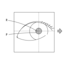
- FIG. 6A and 6B are both enlarged views of the left eye of the facial image 800, with FIG. 6A showing the upright eye and FIG. 6B showing the oblique eye.
- the central position of the pupil P of the left eye and the index image R for eye position measurement appear in a predetermined positional relationship (for example, a predetermined distance and direction).
- the center position of the pupil P of the left eye and the index image R for eye position measurement change from a predetermined positional relationship.
- the central position of the pupil P of the left eye moves outward (toward the ear) of the subject, the position where the index image R for eye position measurement is formed accordingly changes, and the position of the pupil P changes.
- the distance from the center position to the index image R for eye position measurement, the direction in which the index image R for eye position measurement appears with respect to the center position of the pupil P, and the like change.
- the eye position measurement index image R may be predicted where is formed.
- it may be calibrated using a parameter different from the interpupillary distance (for example, corneal shape, etc.), or it may be calibrated using both the interpupillary distance and a parameter different from the interpupillary distance. good.
- the distance and direction in which the index image R for eye position measurement is formed with respect to the central position of the pupil P of the left eye are obtained as references.
- the interpupillary distance between the left eye and the right eye may be manually input by the examiner by operating the operation unit 76, or may be configured to receive values measured using a device other than the present device. good.
- the control unit 70 acquires the eye position information of the left eye based on the face image 800.
- the control unit 70 analyzes the face image 800 and detects the coordinates of the central position of the pupil P of the left eye and the coordinates of the position where the index image R for eye position measurement is formed.
- the coordinates of the center position may be detected by detecting the pupil from the rise and fall of the luminance of the face image 800 and calculating the center of the pupil.
- the coordinates of the position where the index image R for eye position measurement is formed may be detected from the rise and fall of the brightness of the face image 800 .
- the area to be analyzed may be set in advance.
- the control unit 70 detects the reference positional relationship between the center position of the pupil P of the left eye and the index image R for eye position measurement and the analysis processing of the face image 800 when the subject's eye E is an upright eye. Based on the actual positional relationship between the central position of the pupil P of the left eye and the index image R for eye position measurement, whether or not there is a change in the eye position of the left eye is detected. For example, the control unit 70 may determine that there is no change in eye position when both the distance and direction deviations are within the allowable range in the actual positional relationship with respect to the reference positional relationship. In other words, the subject's eye E may be determined to be an upright eye.
- control unit 70 may determine that there is a change in eye position when at least one of the aforementioned distance and direction is out of the allowable range.
- the subject's eye E may be determined to be an oblique eye.
- the direction and amount of the oblique position may be further determined.
- the presence or absence of the oblique position, or the direction and amount of the oblique position acquired by the control unit 70 as the eye position information is stored in the memory 72 .
- the control unit 70 aligns the measurement unit 100 with respect to the left eye, performs preliminary measurement, addition of fog, and main measurement in order to obtain the eye refractive power of the left eye.
- the line of sight of the left eye moves in the state of monocular vision with the right eye
- the line of sight of the right eye moves in the state of monocular vision with the left eye.
- the direction in which the line of sight of the left eye moves in the state of monocular vision with the right eye may be symmetrical to the direction in which the line of sight of the right eye moves in the state of monocular vision with the left eye.
- exotropia causes the right or left eye to deviate outward (early)
- medial oblique causes the right or left eye to deviate inward (nasal).
- one of the right eye and the left eye is deviated upward (toward the forehead), and the other is deviated downward. That is, if the left eye is determined to be the right eye in step S5, the right eye is likely to be the right eye as well, and if the left eye is determined to be the oblique eye, the right eye is also the oblique eye. Probability is high. Therefore, when measuring the eye refractive power of the left eye, it is not always necessary to measure the eye position of the right eye in parallel. good too. Of course, the eye position information of the right eye may be obtained by measuring the eye position of the right eye in the same manner as the left eye.
- step S ⁇ b>6 the eye refractive power and eye position information of the eye E to be examined are displayed on the display section 75 .
- the control unit 70 causes the display unit 75 to display measurement results such as the spherical powers of the left and right eyes, the cylindrical powers, the astigmatism axis angle, and the like.
- the control unit 70 causes the display unit 75 to display eye position information such as the presence or absence of oblique position of the left eye and the right eye, the direction of the oblique position, the amount of the oblique position, and the like.
- the ophthalmologic apparatus of this embodiment captures the face image of the subject and acquires the eye position information of the eye to be examined based on the face image. Accordingly, it is possible to measure the optical characteristics of the eye to be inspected using the ophthalmologic apparatus, and acquire eye position information of the eye to be inspected with a simple configuration.
- the face photographing means for photographing the face image for the alignment of the eye to be inspected is also used as the face photographing means for acquiring the eye position information of the eye to be inspected. can be configured.
- the ophthalmologic apparatus of this embodiment measures the optical characteristics of the eye to be measured, which is one of the left eye and the right eye.
- a face image including a non-measurement eye that is the other of the right eye and the non-measurement eye that is different from the measurement eye is photographed, and eye position information is acquired based on the face image of the non-measurement eye.
- a facial image including the non-measuring eye is taken while a fixation target is presented to the eye to be measured. There is no need to provide time for photographing, and the extension of measurement time, the burden on the subject, and the like are reduced.
- the ophthalmologic apparatus of this embodiment captures a face image including the non-measurement eye while the measurement eye is presenting the fixation target and the measurement eye is fixating the fixation target.
- the line of sight of the eye to be measured is directed in a predetermined reference direction (here, the front direction), thereby utilizing the change in the eye position of the non-measured eye. Then, eye position information can be easily acquired.
- a predetermined reference direction here, the front direction
- the ophthalmologic apparatus of the present embodiment provides calibration data based on the positional relationship between the corneal bright spot image formed on the eye to be inspected and the pupil of the eye to be inspected, and the corneal bright spot image and the pupil included in the face image.
- eye position information is acquired based on the positional relationship of
- eye position information can be easily obtained from changes in the positional relationship between the corneal bright spot image and the pupil with respect to the calibration data, for example, by photographing only one face image.
- the facial image 800 may be acquired at a timing before the alignment of the measurement unit 100 with respect to the subject's eye E is performed and the right eye becomes monocular.
- the face image 800 is displayed at the timing when it is detected that the subject's face is fixed by the face support unit 3, the forehead is in contact with the forehead rest, the chin is placed on the chinrest, and the like. may be obtained.
- the control unit 70 may determine the presence or absence of squint, the direction and amount of squint, and the like by analyzing the facial image 800 .
- the face illumination optical system 600 may include one illumination light source 601 or multiple illumination light sources 601 .
- the face illumination optical system 600 includes a plurality of illumination light sources 601, a plurality of index images R for eye position measurement formed on the cornea by these illumination light sources 601, the center position of the pupil P, The eye position of the subject's eye E can be measured based on the positional relationship of .
- at least one of the plurality of illumination light sources 601 may be turned on and the rest may be turned off to form at least one index image R for eye position measurement.
- the index image R for eye position measurement is not necessarily formed at the vertex position of the cornea.
- it is formed at a position shifted from the vertex position of the cornea due to the arrangement of the face illumination optical system 600 with respect to the subject.
- the eye position information can be obtained based on the change in the positional relationship between the eye position measurement target image R and the center position of the pupil P included in the face image.
- the face illumination optical system 600 may also be used as an illumination optical system for purposes other than face illumination.
- it also serves as an optical system for illuminating the subject's eye E and obtaining corneal information (eg, corneal diameter, etc.) and pupil information (eg, pupil diameter, interpupillary distance, etc.) of the subject's eye E.
- corneal information eg, corneal diameter, etc.
- pupil information eg, pupil diameter, interpupillary distance, etc.
- an illumination optical system separately provided for a purpose other than illumination of the face may also be used as the face illumination optical system 600 .
- the interpupillary distance between the left eye and the right eye is determined by the examiner inputting a value by operating the operation unit 76 or by receiving a previously measured value using another device.
- the acquired configuration has been described as an example, it is not limited to this.
- the interpupillary distance may be acquired based on the amount of movement of the measurement unit 100 when the alignment of the measurement unit 100 with respect to the right eye is completed and when the alignment of the measurement unit 100 with respect to the left eye is completed. At this time, even if the subject's eye E is an oblique eye, the left eye and the right eye each face the front (the line of sight does not move) when the alignment is completed.
- the reference positional relationship between the center position of the pupil P of the left eye in the face image 800 and the index image R for eye position measurement is calibrated at any timing after the alignment of the measurement unit 100 with respect to the left eye is completed.
- analysis processing of the face image 800 photographed in the eye position measurement of the left eye may be performed.
- the configuration for calibrating the deviation of the positional relationship between the left eye and the illumination light source 601 using the interpupillary distance of the subject's eye has been described as an example, but the present invention is not limited to this.
- the position of the right eye in the facial image 800 is constant (substantially constant).
- the position of the left eye may be detected using the position of the right eye in the face image 800 as a reference, and the deviation of the positional relationship between the left eye and the illumination light source 601 may be calibrated according to the position of the left eye. Thereby, the position where the eye position measurement index image R is formed is predicted.
- one facial image 800 is photographed, and the change in eye position is determined based on the reference positional relationship obtained by calibration and the actual positional relationship detected by the analysis processing of the facial image 800.
- the configuration for detecting the presence/absence has been described as an example, the present invention is not limited to this.
- two face images 800 are photographed, one in which the right eye does not fixate the fixation target, and the other in which the right eye fixates on the fixation target. It is good also as a structure which detects the presence or absence of.
- two face images 800 may be captured, one with the light source 301 of the fixation target optical system 300 turned on and the other with the light source 301 turned off.
- the control unit 70 compares the positional relationship between the center position of the pupil P and the index image R for eye position measurement detected from the analysis processing of these face images, and determines the eye position of at least one of the right eye and the left eye. You can also ask for a change in
- two face images 800 may be taken at the time when the alignment of the measurement unit 100 for the right eye is completed and when the alignment of the measurement unit 100 for the left eye is completed.
- the first face image is obtained with the right eye fixed and the left eye is not fixed
- the left eye alignment is completed
- the left eye is fixed and the first face image is obtained.
- a second facial image is obtained in which the right eye is not fixated. Therefore, the control unit 70 compares the positional relationship between the center position of the pupil P detected by the analysis processing of the first face image and the second face image and the index image R for eye position measurement, and determines whether the right eye or the left eye. A change in eye position of at least one of the eyes may be determined.
- two face images 800 are photographed in the above description, it is possible to detect the presence or absence of a change in eye position by photographing one face image 900 in place of the anterior eye segment image 900 .
- the face image 800 is photographed to acquire the facial image in a state in which the left eye is not fixed, and when the alignment of the measurement unit 100 with the left eye is completed, the left eye is captured.
- the anterior segment image 900 may be photographed to obtain an anterior segment image with the left eye fixed.
- the control unit 70 may detect the center position of the pupil P and the index image R for eye position measurement from each image, compare their positional relationships, and obtain changes in eye position.
- the face photographing optical system 700 and the observation optical system 500 are different in the arrangement of the imaging element with respect to the subject's eye E, the angle of view of the imaging element, and the like.
- the change in the eye position may be obtained in consideration of the position of the left eye detected from the partial image and the deviation in the XYZ directions.
- the ophthalmologic apparatus of the present embodiment may capture the anterior segment image of the subject's eye and the face image in this way, and acquire the eye position information based on these images. This makes it possible to easily acquire the eye position information, for example, from changes in the positional relationship between the corneal bright spot image and the pupil in the anterior segment image and the face image.
- the configuration for acquiring the eye position information of the subject's eye based on at least the face image of the subject's eye has been described as an example, but the present invention is not limited to this.
- the configuration may be such that the eye position information of the subject's eye is corrected using an alignment index image projected onto the cornea of the subject's eye and an anterior segment image including the alignment index image obtained by photographing the subject's eye.
- the face image 800 is photographed when the alignment of the measuring unit 100 with respect to the right eye is completed, and the eye position information of the left eye is obtained by obtaining the face image in a state where the left eye is not fixated.
- the eye position information of the left eye may be corrected by capturing the anterior segment image 900 of the left eye when the alignment of the measurement unit 100 with respect to the left eye is completed.
- the center position of the pupil and the center position of the alignment index image that is, the vertex position of the cornea
- the control unit 70 may correct the eye position information in consideration of these positional relationships based on the anterior segment image 900 .
- the eye position of the left eye is measured (the face image 800 is captured) while the right eye is clearly observing the fixation target.
- the eye position of the left eye may be measured while the right eye observes the fixation target in a blurred manner. More specifically, when the fixation target plate 302 is moved to the cloudy completion position in step S3, or when the main measurement images are continuously captured in step S4, at least one of the timings, Alignment of the left eye may be performed.
- the ophthalmologic apparatus of the present embodiment can capture a face image including the non-measurement eye while the fixation target is presented to the measurement eye and the fog is added to the measurement eye. good.
- the time for adding fog to the eye to be measured (for example, the time for the fixation target plate to wait at the fog completion position) may be set to a sufficient length so that the accommodation of the eye to be measured is released appropriately. be. Therefore, in a state in which fog is added to the eye to be measured, the time required for photographing the face image is less likely to run short, and the eye position information can be acquired more efficiently.
- control unit 100 measurement unit 200 measurement optical system 300 fixation target optical system 400 index projection optical system 500 observation optical system 600 face illumination optical system 700 face photographing optical system
Landscapes
- Health & Medical Sciences (AREA)
- Life Sciences & Earth Sciences (AREA)
- Engineering & Computer Science (AREA)
- Medical Informatics (AREA)
- Surgery (AREA)
- Biophysics (AREA)
- Biomedical Technology (AREA)
- Heart & Thoracic Surgery (AREA)
- Physics & Mathematics (AREA)
- Molecular Biology (AREA)
- Ophthalmology & Optometry (AREA)
- Animal Behavior & Ethology (AREA)
- General Health & Medical Sciences (AREA)
- Public Health (AREA)
- Veterinary Medicine (AREA)
- Human Computer Interaction (AREA)
- Eye Examination Apparatus (AREA)
Priority Applications (1)
| Application Number | Priority Date | Filing Date | Title |
|---|---|---|---|
| JP2023576867A JPWO2023145638A1 (https=) | 2022-01-31 | 2023-01-20 |
Applications Claiming Priority (2)
| Application Number | Priority Date | Filing Date | Title |
|---|---|---|---|
| JP2022013511 | 2022-01-31 | ||
| JP2022-013511 | 2022-01-31 |
Publications (1)
| Publication Number | Publication Date |
|---|---|
| WO2023145638A1 true WO2023145638A1 (ja) | 2023-08-03 |
Family
ID=87471782
Family Applications (1)
| Application Number | Title | Priority Date | Filing Date |
|---|---|---|---|
| PCT/JP2023/001678 Ceased WO2023145638A1 (ja) | 2022-01-31 | 2023-01-20 | 眼科装置及び眼科プログラム |
Country Status (2)
| Country | Link |
|---|---|
| JP (1) | JPWO2023145638A1 (https=) |
| WO (1) | WO2023145638A1 (https=) |
Citations (3)
| Publication number | Priority date | Publication date | Assignee | Title |
|---|---|---|---|---|
| JP2018110726A (ja) * | 2017-01-12 | 2018-07-19 | 株式会社ニデック | 自覚式検眼装置及び自覚式検眼プログラム |
| JP2019063238A (ja) * | 2017-09-29 | 2019-04-25 | 株式会社ニデック | 眼科装置 |
| JP2020054784A (ja) * | 2018-09-27 | 2020-04-09 | 株式会社トプコン | 眼科装置 |
-
2023
- 2023-01-20 WO PCT/JP2023/001678 patent/WO2023145638A1/ja not_active Ceased
- 2023-01-20 JP JP2023576867A patent/JPWO2023145638A1/ja active Pending
Patent Citations (3)
| Publication number | Priority date | Publication date | Assignee | Title |
|---|---|---|---|---|
| JP2018110726A (ja) * | 2017-01-12 | 2018-07-19 | 株式会社ニデック | 自覚式検眼装置及び自覚式検眼プログラム |
| JP2019063238A (ja) * | 2017-09-29 | 2019-04-25 | 株式会社ニデック | 眼科装置 |
| JP2020054784A (ja) * | 2018-09-27 | 2020-04-09 | 株式会社トプコン | 眼科装置 |
Also Published As
| Publication number | Publication date |
|---|---|
| JPWO2023145638A1 (https=) | 2023-08-03 |
Similar Documents
| Publication | Publication Date | Title |
|---|---|---|
| CN106963335B (zh) | 主观式检眼装置 | |
| EP2422691A1 (en) | Ophthalmologic device | |
| US20180192867A1 (en) | Subjective optometry apparatus, subjective optometry method, and recording medium storing subjective optometry program | |
| JP6613103B2 (ja) | 眼科装置 | |
| JP6853496B2 (ja) | 検眼装置及び検眼プログラム | |
| US10470658B2 (en) | Optometry apparatus and optometry program | |
| US20190099072A1 (en) | Ophthalmic device | |
| US20180064339A1 (en) | Subjective optometry apparatus and subjective optometry program | |
| CN107788946B (zh) | 主观式验光装置及主观式验光程序 | |
| JP7459491B2 (ja) | 眼科測定装置 | |
| JP7143577B2 (ja) | 眼科装置 | |
| JP7266375B2 (ja) | 眼科装置及びその作動方法 | |
| JP6589378B2 (ja) | 眼科測定装置 | |
| JP6634765B2 (ja) | 眼科装置、および眼科装置制御プログラム | |
| JP6788445B2 (ja) | 眼科装置 | |
| JP2018038788A (ja) | 自覚式検眼装置及び自覚式検眼プログラム | |
| JP2017213125A (ja) | 眼科装置 | |
| JP6060525B2 (ja) | 眼底検査装置 | |
| JP6003234B2 (ja) | 眼底撮影装置 | |
| JP6853495B2 (ja) | 自覚式検眼装置及び自覚式検眼プログラム | |
| WO2023074579A1 (ja) | 眼屈折測定装置、および眼屈折測定プログラム | |
| JP2023150640A (ja) | 検眼装置 | |
| WO2023145638A1 (ja) | 眼科装置及び眼科プログラム | |
| JP6823339B2 (ja) | 眼科装置 | |
| JP5562621B2 (ja) | 眼科装置 |
Legal Events
| Date | Code | Title | Description |
|---|---|---|---|
| 121 | Ep: the epo has been informed by wipo that ep was designated in this application |
Ref document number: 23746851 Country of ref document: EP Kind code of ref document: A1 |
|
| WWE | Wipo information: entry into national phase |
Ref document number: 2023576867 Country of ref document: JP |
|
| NENP | Non-entry into the national phase |
Ref country code: DE |
|
| 122 | Ep: pct application non-entry in european phase |
Ref document number: 23746851 Country of ref document: EP Kind code of ref document: A1 |