WO2023145481A1 - アンテナ装置 - Google Patents
アンテナ装置 Download PDFInfo
- Publication number
- WO2023145481A1 WO2023145481A1 PCT/JP2023/000748 JP2023000748W WO2023145481A1 WO 2023145481 A1 WO2023145481 A1 WO 2023145481A1 JP 2023000748 W JP2023000748 W JP 2023000748W WO 2023145481 A1 WO2023145481 A1 WO 2023145481A1
- Authority
- WO
- WIPO (PCT)
- Prior art keywords
- base
- antenna
- corner
- antenna device
- viewed
- Prior art date
- Legal status (The legal status is an assumption and is not a legal conclusion. Google has not performed a legal analysis and makes no representation as to the accuracy of the status listed.)
- Ceased
Links
Images

Classifications
-
- H—ELECTRICITY
- H01—ELECTRIC ELEMENTS
- H01Q—ANTENNAS, i.e. RADIO AERIALS
- H01Q21/00—Antenna arrays or systems
- H01Q21/28—Combinations of substantially independent non-interacting antenna units or systems
-
- H—ELECTRICITY
- H01—ELECTRIC ELEMENTS
- H01Q—ANTENNAS, i.e. RADIO AERIALS
- H01Q1/00—Details of, or arrangements associated with, antennas
- H01Q1/12—Supports; Mounting means
- H01Q1/22—Supports; Mounting means by structural association with other equipment or articles
-
- H—ELECTRICITY
- H01—ELECTRIC ELEMENTS
- H01Q—ANTENNAS, i.e. RADIO AERIALS
- H01Q1/00—Details of, or arrangements associated with, antennas
- H01Q1/27—Adaptation for use in or on movable bodies
- H01Q1/32—Adaptation for use in or on road or rail vehicles
-
- H—ELECTRICITY
- H01—ELECTRIC ELEMENTS
- H01Q—ANTENNAS, i.e. RADIO AERIALS
- H01Q1/00—Details of, or arrangements associated with, antennas
- H01Q1/27—Adaptation for use in or on movable bodies
- H01Q1/32—Adaptation for use in or on road or rail vehicles
- H01Q1/325—Adaptation for use in or on road or rail vehicles characterised by the location of the antenna on the vehicle
- H01Q1/3275—Adaptation for use in or on road or rail vehicles characterised by the location of the antenna on the vehicle mounted on a horizontal surface of the vehicle, e.g. on roof, hood, trunk
-
- H—ELECTRICITY
- H01—ELECTRIC ELEMENTS
- H01Q—ANTENNAS, i.e. RADIO AERIALS
- H01Q9/00—Electrically-short antennas having dimensions not more than twice the operating wavelength and consisting of conductive active radiating elements
- H01Q9/04—Resonant antennas
- H01Q9/30—Resonant antennas with feed to end of elongated active element, e.g. unipole
Definitions
- the present invention relates to an antenna device.
- an antenna device includes a base, a case forming a housing space, and an antenna element housed in the housing space.
- the base has a metal base and a metal plate electrically connected to the metal base.
- an appropriate metal plate is used according to the type of vehicle and the type of antenna element to be mounted. As a result, the reduction in antenna gain due to unnecessary resonance is suppressed without changing the metal base in various antenna devices.
- the pull-out direction of the antenna cable of the antenna device may be limited due to restrictions on the vehicle side in which the antenna device is mounted. Therefore, different antenna bases are required depending on the direction in which the antenna cable is pulled out.
- An example of the object of the present invention is to reduce the manufacturing cost of a plurality of types of antenna devices having different antenna cable lead-out directions. Other objects of the present invention will become clear from the description herein.
- One aspect of the present invention is a base; an antenna element at least partially attached to the base; with In the antenna device, a first mounting structure capable of mounting the at least part of the antenna element to the base is arranged at a position substantially symmetrical to the position where the antenna element is mounted with respect to the center of the base.
- FIG. 1 is a schematic top view of a vehicle according to an embodiment
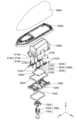
- FIG. 1 is an exploded perspective view of a first antenna device according to an embodiment
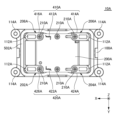
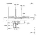
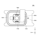
- FIG. FIG. 4 is a top view of the first antenna device according to the embodiment with the first inner case, the first outer case, and the first outer pad removed; It is a left side view in the state where the 1st inner case, the 1st outer case, and the 1st outer pad were removed from the 1st antenna device concerning an embodiment. It is a bottom view of the state where the 1st inner case, the 1st outer case, and the 1st outer pad were removed from the 1st antenna device concerning an embodiment.
- FIG. 1 is a schematic top view of a vehicle according to an embodiment
- FIG. 1 is an exploded perspective view of a first antenna device according to an embodiment
- FIG. 4 is a top view of the first antenna device according to the embodiment with the first inner case, the first outer case, and the first outer pad removed
- It is a left side view in the state
- 10 is a top view of the second antenna device according to the embodiment with the second inner case, the second outer case and the second outer pad removed; It is a left side view in the state where the 2nd inner case, the 2nd outer case, and the 2nd outer pad were removed from the 2nd antenna device concerning an embodiment. It is a bottom view of the state where the 2nd inner case, the 2nd outer case, and the 2nd outer pad were removed from the 2nd antenna device concerning an embodiment.
- the types of antennas mounted on vehicles have increased.
- multiple antennas of the same type may be installed in order to improve transmission and reception performance. Therefore, it may be difficult to mount all the antenna elements in one antenna device. Therefore, it is also being considered to divide a plurality of types of antenna elements into a plurality of types of antenna devices and mount these plurality of types of antenna elements on a vehicle.
- the antenna device If there is only one antenna device mounted on the roof of the vehicle, it is common to mount the antenna device at the front or rear central position of the vehicle. However, when mounting two antenna devices on the roof of the vehicle, it is conceivable to mount the antenna devices on each of the rear right side and the rear left side of the vehicle. When the antenna device is installed in such a position, in order to route the antenna cable under the roof of the vehicle, pull out the antenna cable extending from the antenna device installed on the rear right side of the vehicle to the left side of the vehicle, It is necessary to pull out the antenna cable extending from the antenna device mounted on the rear left side to the right side of the vehicle.
- the direction in which the antenna cable is pulled out may vary.
- the structures of the bases of these two antenna devices should be different.
- using bases with different structures for each of these two antenna devices increases the manufacturing cost of the antenna devices.
- FIG. 1 is a schematic top view of the vehicle 5 according to the embodiment.
- the direction of the arrow indicating the first direction X or the second direction Y is that the direction from the base end to the tip of the arrow is the positive direction of the direction indicated by the arrow, and the direction from the tip of the arrow to the base end is the positive direction. It indicates that the direction indicated by the arrow is the negative direction.
- a white circle with a black dot indicating the third direction Z indicates that the direction from the back to the front of the paper is the positive direction of the third direction Z, and the direction from the front to the back of the paper is the negative direction of the third direction Z. showing.
- the first direction X is a direction parallel to the longitudinal direction of the vehicle 5 .
- the positive direction of the first direction X is the direction from the rear to the front of the vehicle 5 .
- the negative direction of the first direction X is the direction from the front to the rear of the vehicle 5 .
- the second direction Y is perpendicular to the first direction X and parallel to the left-right direction of the vehicle 5 .
- the positive direction of the second direction Y is the direction from the right to the left of the vehicle 5 as viewed from above the vehicle 5 .
- the negative direction of the second direction Y is the direction from the left side to the right side of the vehicle 5 as viewed from above the vehicle 5 .
- the third direction Z is orthogonal to both the first direction X and the second direction Y, and is parallel to the vertical direction of the vehicle 5 .
- the positive direction of the third direction Z is the direction from below to above the vehicle 5 .
- a negative direction of the third direction Z is a direction from above the vehicle 5 to below.
- the vehicle 5 is, for example, a vehicle such as a truck or a passenger car.
- a first antenna device 10A and a second antenna device 10B are mounted on the roof 5a of the vehicle 5. As shown in FIG.
- the first antenna device 10A is mounted on the rear right side of the roof 5a.
- the second antenna device 10B is mounted on the rear left side of the roof 5a.
- FIG. 2 is an exploded perspective view of the first antenna device 10A according to the embodiment.
- the arrow indicating the third direction Z has a positive direction of the third direction Z in the direction from the base end to the tip of the arrow, and a negative direction of the third direction Z in the direction from the tip of the arrow to the base end. It shows that
- the first antenna device 10A includes a first base 100A, a first mounting seal member 102A, a first substrate 200A, a first antenna element 410A, a second antenna element 420A, a first inner case 500A, a first inner pad 502A, a first It has an outer case 600A, a first outer pad 602A and a first fastener 700A.
- the first antenna element 410A has a first element 412A, a second element 414A and a third element 416A.
- the second antenna element 420A has a fourth element 422A, a fifth element 424A and a sixth element 426A.
- the first fastener 700A has a first fastening screw 710A, a first washer 720A and a first holder 730A. As shown in later-described FIGS. 4 and 5, the first antenna device 10A further includes a first connector 300A. For simplicity of explanation, FIG. 2 does not show the first connector 300A.
- the first base 100A is made of metal, for example.
- the first base 100A is mounted on the upper surface side of the roof 5a via a first mounting seal member 102A.
- the first mounting seal member 102A is made of an elastic material such as elastomer or rubber.
- the first mounting seal member 102A serves as a surrounding body surrounding the first connector 300A and the first fastener 700A.
- the first substrate 200A is positioned above the first base 100A.
- the first substrate 200A is, for example, a printed circuit board (PCB).
- the first substrate 200A is attached to the first base 100A by six first substrate attachment screws 210A.
- the first connector 300A is positioned below the first substrate 200A.
- the first connector 300A is connected to the lower surface of the first board 200A by soldering. With the first board 200A attached to the first base 100A, the first connector 300A is inserted through the first insertion hole 104A provided in the first base 100A. In embodiments, the first connector 300A is located behind the first fastener 700A.
- the first antenna element 410A is, for example, a Wi-Fi (registered trademark) antenna.
- the first antenna element 410A is arranged above the first base 100A via the first substrate 200A. When viewed from above, the first antenna element 410A is located on the right side of the center of the first base 100A in the second direction Y.
- the first antenna element 410A is an array antenna composed of a first element 412A, a second element 414A and a third element 416A.
- the first element 412A, the second element 414A and the third element 416A are monopole elements substantially parallel to the third direction Z.
- the first element 412A, the second element 414A and the third element 416A are arranged substantially parallel to the first direction X.
- the first element 412A is positioned in the first direction X between the second element 414A and the third element 416A.
- the second element 414A is positioned behind the first element 412A.
- the third element 416A is located in front of the first element 412A.
- the second antenna element 420A is, for example, a Bluetooth (registered trademark) antenna.
- the second antenna element 420A is arranged above the first base 100A via the first substrate 200A. When viewed from above, the second antenna element 420A is positioned on the left side of the center of the first base 100A in the second direction Y.
- the second antenna element 420A is an array antenna composed of a fourth element 422A, a fifth element 424A and a sixth element 426A.
- the fourth element 422A, the fifth element 424A and the sixth element 426A are monopole elements substantially parallel to the third direction Z.
- the fourth element 422A, the fifth element 424A and the sixth element 426A are arranged substantially parallel to the first direction X.
- the fourth element 422A is positioned in the first direction X between the fifth element 424A and the sixth element 426A.
- the fifth element 424A is positioned behind the fourth element 422A.
- the sixth element 426A is located in front of the fourth element 422A.
- the first inner case 500A is mounted on the upper surface side of the first base 100A via the first inner pad 502A.
- the first inner pad 502A is made of an elastic material such as elastomer or rubber.
- the first inner pad 502A serves as a surrounding body surrounding the first substrate 200A, the first antenna element 410A and the second antenna element 420A.
- the first inner case 500A covers the first substrate 200A, the first antenna element 410A and the second antenna element 420A from above the first base 100A.
- the first inner case 500A together with the first base 100A, forms an accommodation space for accommodating the first substrate 200A, the first antenna element 410A and the second antenna element 420A.
- the first inner case 500A is attached to the first base 100A by four first case attachment screws 510A.
- the first outer case 600A is mounted on the upper surface side of the roof 5a via the first outer pad 602A.
- the first outer pad 602A is made of an elastic material such as elastomer or rubber.
- the portion from the center portion of the first outer pad 602A in the first direction X to the end portion on the negative side of the first direction X includes the first base 100A, the first substrate 200A, the first It is a surrounding body surrounding the antenna element 410A, the second antenna element 420A and the first inner case 500A.
- the first fastener 700A fastens the first base 100A to the roof 5a and electrically grounds the first base 100A to the roof 5a.
- the roof 5a is provided with a mounting hole for mounting the first antenna device 10A.
- the first holder 730A is arranged inside this mounting hole.
- the first washer 720A is held by a first holder 730A.
- the first fastening screw 710A penetrates in the third direction Z through a through hole provided in the first washer 720A and is screwed into a screw hole provided in the lower surface of the first base 100A.
- the tip of the claw provided on the first washer 720A contacts the lower surface of the roof 5a.
- the first base 100A is fastened to the roof 5a.
- the first base 100A is electrically grounded to the roof 5a via the first fastening screw 710A and the first washer 720A.
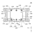
- FIG. 3 is a top view of a state in which the first inner case 500A, the first outer case 600A and the first outer pad 602A are removed from the first antenna device 10A according to the embodiment.
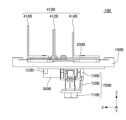
- FIG. 4 is a left side view of the first antenna device 10A according to the embodiment with the first inner case 500A, the first outer case 600A and the first outer pad 602A removed.
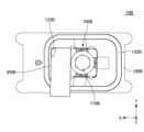
- FIG. 5 is a bottom view of the first antenna device 10A according to the embodiment with the first inner case 500A, the first outer case 600A and the first outer pad 602A removed.
- FIG. 6 is a top view of a state in which the second inner case, the second outer case and the second outer pad are removed from the second antenna device 10B according to the embodiment.
- FIG. 4 is a left side view of the first antenna device 10A according to the embodiment with the first inner case 500A, the first outer case 600A and the first outer pad 602A removed.
- FIG. 5 is a bottom view of the first antenna device 10A according to the embodiment with the first
- FIG. 7 is a left side view of the second antenna device 10B according to the embodiment with the second inner case, the second outer case and the second outer pad removed.
- FIG. 8 is a bottom view of a state in which the second inner case, the second outer case and the second outer pad are removed from the second antenna device 10B according to the embodiment.
- the white circle with a black dot indicating the second direction Y is the positive direction of the second direction Y from the back to the front of the paper, and the second direction Y is the direction from the front to the back of the paper. is in the negative direction.
- the white circle with X indicating the third direction Z is the positive direction of the third direction Z from the front to the back of the paper, and the third direction Z is the direction from the back to the front of the paper. is in the negative direction.
- the second antenna device 10B includes a second base 100B, a second mounting seal member 102B, a second substrate 200B, a second connector 300B, a third antenna element 410B, a second 2 inner pad 502B and second fastener 700B.
- the second antenna device 10B according to the embodiment includes a second inner case (not shown) in the same manner as the first inner case 500A, the first outer case 600A, and the first outer pad 602A of the first antenna device 10A according to the embodiment. , a second outer case and a second outer pad. As mentioned above, the second inner case, the second outer case and the second outer pad are removed in FIGS. 6-8.
- the third antenna element 410B has a seventh element 412B, an eighth element 414B and a ninth element 416B.
- the second fastener 700B has a second fastening screw 710B, a second washer 720B and a second holder 730B.
- first connector 300A covers the first pins 122A, which will be described later, from below the first base 100A. Accordingly, in FIG. 5, the first pin 122A is shown transparently through the first connector 300A. Similarly, the second connector 300B covers the second pins 122B described below from below the second base 100B. Therefore, in FIGS. 7 and 8, the second pin 122B is shown transparently through the second connector 300B.
- the first antenna device 10A and the second antenna device 10B will be compared with reference to FIGS. 3 to 8 and, if necessary, FIGS. 1 and 2.
- FIG. 1 The first antenna device 10A and the second antenna device 10B will be compared with reference to FIGS. 3 to 8 and, if necessary, FIGS. 1 and 2.
- FIG. 1 The first antenna device 10A and the second antenna device 10B will be compared with reference to FIGS. 3 to 8 and, if necessary, FIGS. 1 and 2.
- the structure such as dimensions and shape of the first base 100A and the structure such as dimensions and shape of the second base 100B are substantially the same. Therefore, compared to the case where the structure of the first base 100A and the structure of the second base 100B are different, the manufacturing cost of the first antenna device 10A and the second antenna device 10B can be reduced.
- the orientation of the first base 100A in the first direction X and the direction of the second base 100A By making the direction of the antenna 100B different in the first direction X, it is possible to make the lead-out direction of the first antenna cable of the first antenna device 10A and the lead-out direction of the second antenna cable of the second antenna device 10B different. Therefore, in the embodiment, compared to the case where the structure of the first base 100A and the structure of the second base 100B are different from each other, it is possible to reduce the manufacturing cost of a plurality of types of antenna devices in which the directions of drawing out the antenna cables are different from each other. .
- the antenna device provided in the first antenna device 10A can be substantially the same as the structure and position of the antenna element provided in the second antenna device 10B.
- first antenna cable (not shown) is connected to the side surface of the first connector 300A on the positive side in the second direction Y.
- the other end of the first antenna cable is electrically connected to an electric device (not shown) provided on the vehicle 5 .
- the first antenna device 10A is mounted on the rear right side of the vehicle 5. As shown in FIG. Therefore, the first antenna cable cannot be pulled out to the right side of the first base 100A when viewed from above, and must be pulled out to the left side of the first base 100A when viewed from above.
- the first connector 300A is configured to pull out the first antenna cable in a direction other than the third direction Z perpendicular to the first base 100A.
- the first connector 300A is configured to pull out the first antenna cable toward the positive direction side of the second direction Y of the first antenna device 10A.
- a first pin 122A is provided on the lower surface of the first base 100A.
- the first pin 122A is positioned behind the first fastener 700A and on the negative side in the second direction Y of the first connector 300A.
- the first pin 122A is provided to prevent the first base 100A from rotating together with the rotation of the first fastening screw 710A when the first fastening screw 710A is screwed into the screw hole provided on the bottom surface of the first base 100A.
- the first antenna cable needs to be pulled out toward the side opposite to the side where the first pin 122A is located with respect to the first connector 300A. . Therefore, as described above, the first antenna cable can be pulled out toward the side opposite to the side where the first pin 122A is located with respect to the first connector 300A.
- One end of a second antenna cable (not shown) is connected to the side surface of the second connector 300B on the negative direction side in the second direction Y.
- the other end of the second antenna cable is electrically connected to an electric device (not shown) provided on the vehicle 5 .
- the second antenna device 10B is mounted on the rear left side of the vehicle 5.
- the second connector 300B is configured to pull out the second antenna cable in a direction other than the third direction Z perpendicular to the second base 100B.
- the second connector 300B is configured to pull out the second antenna cable toward the negative direction side of the second direction Y of the second antenna device 10B.
- a second pin 122B is provided on the lower surface of the second base 100B.
- the second pin 122B is located in front of the second fastener 700B and on the positive side in the second direction Y of the second connector 300B.
- the second pin 122B is provided to prevent the second base 100B from rotating together with the rotation of the second fastening screw 710B when the second fastening screw 710B is screwed into the screw hole provided on the bottom surface of the second base 100B.
- the second antenna cable needs to be pulled out toward the side opposite to the side where the second pin 122B is located with respect to the second connector 300B. . Therefore, as described above, the second antenna cable can be pulled out toward the side opposite to the side where the second pin 122B is located with respect to the second connector 300B.
- the orientation in the first direction X of the first base 100A and the orientation in the first direction X of the second base 100B are opposite to each other in the first direction X. Therefore, the first antenna cable can be pulled out toward the left side of the first antenna device 10A, and the second antenna cable can be pulled out toward the right side of the second antenna device 10B. In this way, in the embodiment, by making the directions of the bases of the antenna devices different, it is possible to make the lead-out directions of the antenna cables of the antenna devices different from each other.
- the first substrate 200A when viewed from the third direction Z, has a substantially square shape.
- the shape of the first substrate 200A is not limited to this example.
- Four first ribs 112A are provided on the upper surface of the first base 100A.
- the left front corner of the first substrate 200A viewed from above will be referred to as a first corner 202A as required.
- the left rear corner of the first substrate 200A as viewed from above is referred to as a second corner 204A as required.
- the right rear corner of the first substrate 200A as viewed from above is referred to as a third corner 206A, as required.
- the right front corner of the first substrate 200A as viewed from above is referred to as a fourth corner 208A, as required.
- the lower end of the first element 412A is attached to the first substrate 200A by soldering, for example. As shown in FIG. 3, when viewed from the third direction Z, the first element 412A is arranged closer to the fourth corner 208A in the first direction X than to the third corner 206A. However, the position where the first element 412A is arranged is not limited to this example.
- the portion of the lower end of the second element 414A that overlaps with the third corner 206A in the third direction Z is secured together with the third corner 206A by the first board mounting screw 210A provided at the third corner 206A. 1 base 100A.
- a through hole through which the first rib 112A positioned behind the third corner 206A is inserted in the third direction Z is provided at the rear portion of the third corner 206A at the lower end of the second element 414A.
- the second element 414A is aligned by inserting the first rib 112A into the through hole of the second element 414A.
- the portion of the lower end of the third element 416A that overlaps the fourth corner 208A in the third direction Z is secured to the fourth corner 208A and the fourth corner 208A by the first board mounting screw 210A provided at the fourth corner 208A. 1 base 100A.
- a through hole through which the first rib 112A positioned in front of the fourth corner 208A is inserted in the third direction Z is provided in the front portion of the fourth corner 208A at the lower end of the third element 416A.
- the third element 416A is aligned by inserting the first rib 112A into the through hole of the third element 416A.
- the lower end of the fourth element 422A is attached to the first substrate 200A by soldering, for example.
- the fourth element 422A is arranged closer to the first corner 202A in the first direction X than to the second corner 204A when viewed from the third direction Z.
- the position where the fourth element 422A is arranged is not limited to this example.
- the portion of the lower end of the fifth element 424A that overlaps the second corner 204A in the third direction Z is secured to the second corner 204A along with the second corner 204A by the first board mounting screw 210A provided at the second corner 204A. 1 base 100A.
- a through hole through which the first rib 112A positioned behind the second corner 204A is inserted in the third direction Z is provided in the rear portion of the second corner 204A at the lower end of the fifth element 424A.
- the fifth element 424A is aligned by inserting the first rib 112A into the through hole of the fifth element 424A.
- the portion of the lower end of the sixth element 426A that overlaps the first corner 202A in the third direction Z is attached to the first corner 202A along with the first corner 202A by a first board mounting screw 210A provided at the first corner 202A. 1 base 100A.
- a through hole through which the first rib 112A located in front of the first corner 202A is inserted in the third direction Z is provided in the front portion of the first corner 202A at the lower end of the sixth element 426A.
- the sixth element 426A is aligned by inserting the first rib 112A into the through hole of the sixth element 426A.
- the third antenna element 410B is, for example, a Wi-Fi (registered trademark) antenna. As viewed from above, the third antenna element 410B is located on the left side of the center of the second base 100B in the second direction Y. As shown in FIG.
- the third antenna element 410B is an array antenna composed of a seventh element 412B, an eighth element 414B and a ninth element 416B.
- the seventh element 412B, the eighth element 414B and the ninth element 416B are monopole elements substantially parallel to the third direction Z.
- FIG. As shown in FIG. 6, when viewed from the third direction Z, the second substrate 200B has substantially the same shape as the first substrate 200A. Similar to the first substrate 200A, the second substrate 200B is attached to the second base 100B by six second substrate attachment screws 210B. Similarly to the first base 100A, the upper surface of the second base 100B is provided with four second ribs 112B.
- the left front corner of the second substrate 200B as viewed from above will be referred to as the fifth corner 202B as required.
- the left rear corner of the second substrate 200B as viewed from above is referred to as a sixth corner 204B as required.
- the right rear corner of the second substrate 200B as viewed from above is referred to as a seventh corner 206B, as required.
- the right front corner of the second substrate 200B as viewed from above is referred to as an eighth corner 208B, as required.
- the lower end of the seventh element 412B is attached to the second substrate 200B by soldering, for example. As shown in FIG. 6, when viewed from the third direction Z, the seventh element 412B is arranged closer to the fifth corner 202B in the first direction X than to the sixth corner 204B. However, the position where the seventh element 412B is arranged is not limited to this example.
- the portion of the lower end of the eighth element 414B that overlaps the sixth corner 204B in the third direction Z is secured to the sixth corner 204B and the sixth corner 204B by the second board mounting screw 210B provided at the sixth corner 204B. 2 is attached to the base 100B.
- a through hole through which the second rib 112B located behind the sixth corner 204B is inserted in the third direction Z is provided in the rear portion of the sixth corner 204B at the lower end of the eighth element 414B.
- the eighth element 414B is aligned by inserting the second rib 112B into the through hole of the eighth element 414B.
- the portion of the lower end of the ninth element 416B that overlaps the fifth corner 202B in the third direction Z is secured to the fifth corner 202B and the fifth corner 202B by the second board mounting screw 210B provided at the fifth corner 202B. 2 is attached to the base 100B.
- a through hole through which the second rib 112B located in front of the fifth corner 202B is inserted in the third direction Z is provided in the front portion of the fifth corner 202B at the lower end of the ninth element 416B.
- the ninth element 416B is aligned by inserting the second rib 112B into the through hole of the ninth element 416B.
- the elements constituting the antenna elements are not arranged at the seventh corner 206B and the eighth corner 208B.
- the mounting structure capable of mounting at least part of the first antenna element 410A and at least part of the second antenna element 420A to the first base 100A when viewed from the third direction Z is the first It is arranged at a position substantially symmetrical to the position where the first antenna element 410A and the second antenna element 420A are attached with respect to the center of the base 100A.
- the first board mounting screws 210A provided at four corners of the first board 200A and the four first board mounting screws 210A.
- the four first ribs 112A provided in the vicinity of one substrate mounting screw 210A are arranged substantially symmetrically with respect to the center of the first base 100A. Therefore, even if the orientation of the first base 100A in the first direction X and the orientation of the second base 100B in the first direction X are opposite to each other in the first direction X as shown in FIGS.
- the relative positions of the antenna elements with respect to the center of the base when viewed from the third direction Z can be substantially the same.
- the relative position of the second antenna element 420A with respect to the center of the first base 100A and the relative position of the third antenna element 410B with respect to the center of the second base 100B are substantially the same.
- the first fastener 700A overlaps the center of the first base 100A in the third direction Z, as shown in FIG.
- At least a portion of the second fastener 700B overlaps the center of the second base 100B in the third direction Z, as shown in FIG. Therefore, even if the orientation of the first base 100A in the first direction X and the orientation of the second base 100B in the first direction X are opposite to each other in the first direction X, the roof 5a can be seen from the third direction Z.
- the relative position of the first antenna element 410A or the second antenna element 420A to the mounting hole for the first base 100A, and the relative position of the third antenna element 410B to the mounting hole for the second base 100B of the roof 5a. can be made substantially identical.
- the first base 100A has substantially two-fold symmetry when viewed from the third direction Z. Therefore, the shape of the portion of the first outer pad 602A surrounding the first base 100A and the shape of the portion of the second outer pad (not shown) surrounding the second base 100B can be substantially the same. Therefore, the manufacturing cost of the first antenna device 10A and the second antenna device 10B can be reduced compared to the case where the first base 100A is asymmetric when viewed from the third direction Z.
- first screw holes 114A are provided on the upper surface of the first base 100A.
- the first base 100A has a pair of long sides substantially parallel to the first direction X and a pair of short sides substantially parallel to the second direction Y. ing.
- substantially semicircular protrusions are provided on the left and right ends of each of the pair of short sides of the first base 100A.
- Four first screw holes 114A are provided on the upper surfaces of these four projections.
- Each of the four first case mounting screws 510A shown in FIG. 2 is screwed into each of the four first screw holes 114A.
- the first screw hole 114A and the first case mounting screw 510A function as a mounting structure for mounting at least a portion of the first inner case 500A to the first base 100A.
- the example of the mounting structure for mounting at least part of the first inner case 500A to the first base 100A is not limited to the first screw holes 114A and the first case mounting screws 510A.
- the second base 100B is also provided with four second screw holes 114B in the same manner as the first base 100A.
- the four first screw holes 114A are arranged substantially symmetrically with respect to the center of the first base 100A. Therefore, when viewed from the third direction Z, the relative positions of the four first screw holes 114A to the center of the first base 100A, the relative positions of the four second screw holes 114B to the center of the second base 100B, can be made substantially identical. Therefore, the structure of the first inner case 500A and the structure of the second inner case (not shown) can be substantially the same. Therefore, compared to the case where the structure of the first inner case 500A and the structure of the second inner case (not shown) are different, the manufacturing cost of the first antenna device 10A and the second antenna device 10B can be reduced. can.
- the relative position of at least a portion of the antenna element with respect to the center of the base is substantially the same both before and after rotating the base by 180° when viewed from the third direction Z. can be done.
- at least a portion of the antenna element and a mounting structure capable of mounting at least a portion of the antenna element to the base should be appropriately arranged at substantially symmetrical positions with respect to the center of the base. and the relative position of at least a portion of the antenna element with respect to the center of the base both before rotating the base by (360/n)° and after rotating the base by (360/n)° as viewed from the third direction Z They can also be the same (n is a natural number of 2 or more).
- the antenna element mounted on each base is an array antenna.
- the antenna elements mounted on each base are not limited to array antennas.
- the direction in which the first antenna cable is pulled out from the first antenna device 10A and the direction in which the second antenna cable is pulled out from the second antenna device 10B are left-right reversed.
- the direction in which the first antenna cable is pulled out from the first antenna device 10A and the direction in which the second antenna cable is pulled out from the second antenna device 10B may be reversed.
- Aspect 1 is a base; an antenna element at least partially attached to the base; with In the antenna device, a first mounting structure capable of mounting the at least part of the antenna element to the base is arranged at a position substantially symmetrical to the position where the antenna element is mounted with respect to the center of the base. According to aspect 1, even if the directions of the bases of the plurality of types of antenna devices are made different from each other, the relative positions of the antenna elements with respect to the centers of the bases of the plurality of types of antenna devices can be substantially the same. .
- Aspect 2 is further comprising a case forming a housing space for housing the antenna element, The antenna device according to aspect 1, wherein second mounting structures for mounting at least a portion of the case on the base are arranged substantially symmetrically.
- Aspect 3 is further comprising a fastener for fastening the base to the vehicle; 3. The antenna device according to aspect 1 or 2, wherein at least a portion of the fastener overlaps the center of the base.
- Aspect 4 is The antenna device according to any one of modes 1 to 3, wherein the base is substantially rotationally symmetric when viewed from a predetermined direction. According to aspect 4, even if the directions of the bases of the plurality of types of antenna devices are made different from each other, the shapes of the pads surrounding the respective bases can be made substantially the same. Therefore, compared to the case where the pads surrounding each base have different shapes, it is possible to reduce the manufacturing cost of a plurality of types of antenna devices having different antenna cable lead-out directions.
- Aspect 5 is 5.
- the antenna device according to any one of aspects 1 to 4, wherein the base has a structure in which the antenna cable is pulled out in a predetermined direction other than a direction perpendicular to the base.
- the antenna cable extending from the base can be changed according to the direction of the base. For example, if the base is mounted on the left side of the vehicle, the antenna cable extending from the base can be pulled out to the right side of the vehicle depending on the orientation of the base, and if the base is mounted on the right side of the vehicle, it will extend from the base. The antenna cable can be pulled out to the left side of the vehicle depending on the orientation of the base.
Landscapes
- Engineering & Computer Science (AREA)
- Remote Sensing (AREA)
- Support Of Aerials (AREA)
- Details Of Aerials (AREA)
Abstract
Description
ベースと、
少なくとも一部分が前記ベースに取り付けられたアンテナエレメントと、
を備え、
前記アンテナエレメントの前記少なくとも一部分を前記ベースに取り付け可能な第1取付構造が前記ベースの中心に対して前記アンテナエレメントが取り付けられた位置と略対称な位置に配置されている、アンテナ装置である。
(態様1)
態様1は、
ベースと、
少なくとも一部分が前記ベースに取り付けられたアンテナエレメントと、
を備え、
前記アンテナエレメントの前記少なくとも一部分を前記ベースに取り付け可能な第1取付構造が前記ベースの中心に対して前記アンテナエレメントが取り付けられた位置と略対称な位置に配置されている、アンテナ装置である。
態様1によれば、複数種類のアンテナ装置の各々のベースの向きを互いに異ならせても、複数種類のアンテナ装置の各々においてベースの中心に対するアンテナエレメントの相対的位置を略同一にすることができる。このため、複数種類のアンテナ装置の各々においてベースの構造を略同一にして、複数種類のアンテナ装置の各々のベースの向きを異ならせることで、複数種類のアンテナ装置の各々のアンテナケーブルの引き出し方向を異ならせることができる。したがって、複数種類のアンテナ装置の各々のベースの構造が互いに異なる場合と比較して、アンテナケーブルの引き出し方向が互いに異なる複数種類のアンテナ装置の製造コストを低減することができる。
(態様2)
態様2は、
前記アンテナエレメントを収容する収容空間を形成するケースをさらに備え、
前記ケースの少なくとも一部分を前記ベースに取り付ける第2取付構造が略対称に配置されている、態様1に記載のアンテナ装置である。
態様2によれば、複数種類のアンテナ装置の各々のベースの向きを互いに異ならせても、各ベースに取り付けられるケースの構造を略同一にすることができる。このため、各ベースに取り付けられるケースの構造が互いに異なる場合と比較して、アンテナケーブルの引き出し方向が互いに異なる複数種類のアンテナ装置の製造コストを低減することができる。
(態様3)
態様3は、
前記ベースを車両へ締結する締結具をさらに備え、
前記締結具の少なくとも一部分が前記ベースの前記中心と重なっている、態様1又は2に記載のアンテナ装置である。
態様3によれば、複数種類のアンテナ装置の各々のベースの向きを互いに異ならせても、車両のルーフの各ベース用の取付孔に対するアンテナエレメントの相対的位置を略同一にすることができる。
(態様4)
態様4は、
所定方向から見て前記ベースが略回転対称となっている、態様1~3のいずれか一に記載のアンテナ装置である。
態様4によれば、複数種類のアンテナ装置の各々のベースの向きを互いに異ならせても、各ベースを囲むパッドの形状を略同一にすることができる。このため、各ベースを囲むパッドの形状が互いに異なる場合と比較して、アンテナケーブルの引き出し方向が互いに異なる複数種類のアンテナ装置の製造コストを低減することができる。
(態様5)
態様5は、
前記ベースは、アンテナケーブルを前記ベースに垂直な方向以外の所定の方向に引き出す構成を有している、態様1~4のいずれか一に記載のアンテナ装置である。
態様5によれば、ベースから伸びるアンテナケーブルをベースの向きに応じて変更させることができる。例えば、ベースが車両の左側に搭載されている場合、ベースから伸びるアンテナケーブルをベースの向きに応じて車両の右側に引き出すことができ、ベースが車両の右側に搭載されている場合、ベースから伸びるアンテナケーブルをベースの向きに応じて車両の左側に引き出すことができる。
Claims (5)
- ベースと、
少なくとも一部分が前記ベースに取り付けられたアンテナエレメントと、
を備え、
前記アンテナエレメントの前記少なくとも一部分を前記ベースに取り付け可能な第1取付構造が前記ベースの中心に対して前記アンテナエレメントが取り付けられた位置と略対称な位置に配置されている、アンテナ装置。 - 前記アンテナエレメントを収容する収容空間を形成するケースをさらに備え、
前記ケースの少なくとも一部分を前記ベースに取り付ける第2取付構造が略対称に配置されている、請求項1に記載のアンテナ装置。 - 前記ベースを車両へ締結する締結具をさらに備え、
前記締結具の少なくとも一部分が前記ベースの前記中心と重なっている、請求項1又は2に記載のアンテナ装置。 - 所定方向から見て前記ベースが略回転対称となっている、請求項1~3のいずれか一項に記載のアンテナ装置。
- 前記ベースは、アンテナケーブルを前記ベースに垂直な方向以外の所定の方向に引き出す構成を有している、請求項1~4のいずれか一項に記載のアンテナ装置。
Priority Applications (2)
| Application Number | Priority Date | Filing Date | Title |
|---|---|---|---|
| US18/832,110 US20250149779A1 (en) | 2022-01-26 | 2023-01-13 | Antenna device |
| CN202380018124.XA CN118575364A (zh) | 2022-01-26 | 2023-01-13 | 天线装置 |
Applications Claiming Priority (2)
| Application Number | Priority Date | Filing Date | Title |
|---|---|---|---|
| JP2022-010479 | 2022-01-26 | ||
| JP2022010479A JP7765977B2 (ja) | 2022-01-26 | 2022-01-26 | アンテナ装置 |
Publications (1)
| Publication Number | Publication Date |
|---|---|
| WO2023145481A1 true WO2023145481A1 (ja) | 2023-08-03 |
Family
ID=87471292
Family Applications (1)
| Application Number | Title | Priority Date | Filing Date |
|---|---|---|---|
| PCT/JP2023/000748 Ceased WO2023145481A1 (ja) | 2022-01-26 | 2023-01-13 | アンテナ装置 |
Country Status (4)
| Country | Link |
|---|---|
| US (1) | US20250149779A1 (ja) |
| JP (1) | JP7765977B2 (ja) |
| CN (1) | CN118575364A (ja) |
| WO (1) | WO2023145481A1 (ja) |
Citations (3)
| Publication number | Priority date | Publication date | Assignee | Title |
|---|---|---|---|---|
| JPH06343006A (ja) * | 1993-06-02 | 1994-12-13 | Hitachi Ltd | 車載アンテナ |
| WO2016009685A1 (ja) * | 2014-07-18 | 2016-01-21 | 株式会社ヨコオ | 車載用アンテナ装置 |
| WO2019124518A1 (ja) * | 2017-12-20 | 2019-06-27 | 株式会社ヨコオ | 車載用アンテナ装置 |
Family Cites Families (1)
| Publication number | Priority date | Publication date | Assignee | Title |
|---|---|---|---|---|
| EP3147997A1 (en) | 2015-09-25 | 2017-03-29 | Taoglas Group Holdings | Fin-type antenna assemblies |
-
2022
- 2022-01-26 JP JP2022010479A patent/JP7765977B2/ja active Active
-
2023
- 2023-01-13 US US18/832,110 patent/US20250149779A1/en active Pending
- 2023-01-13 CN CN202380018124.XA patent/CN118575364A/zh active Pending
- 2023-01-13 WO PCT/JP2023/000748 patent/WO2023145481A1/ja not_active Ceased
Patent Citations (3)
| Publication number | Priority date | Publication date | Assignee | Title |
|---|---|---|---|---|
| JPH06343006A (ja) * | 1993-06-02 | 1994-12-13 | Hitachi Ltd | 車載アンテナ |
| WO2016009685A1 (ja) * | 2014-07-18 | 2016-01-21 | 株式会社ヨコオ | 車載用アンテナ装置 |
| WO2019124518A1 (ja) * | 2017-12-20 | 2019-06-27 | 株式会社ヨコオ | 車載用アンテナ装置 |
Also Published As
| Publication number | Publication date |
|---|---|
| CN118575364A (zh) | 2024-08-30 |
| JP7765977B2 (ja) | 2025-11-07 |
| JP2023109085A (ja) | 2023-08-07 |
| US20250149779A1 (en) | 2025-05-08 |
Similar Documents
| Publication | Publication Date | Title |
|---|---|---|
| US11476565B2 (en) | Patch antenna and antenna device for vehicle | |
| US10283907B2 (en) | Floating connector and electronic device module | |
| US20150222064A1 (en) | Receptacle connector, plug connector and connector assembly | |
| JP2019161312A (ja) | パッチアンテナ | |
| JP2021136531A (ja) | 車載用アンテナ装置 | |
| JPWO2019124518A1 (ja) | 車載用アンテナ装置 | |
| US20120276757A1 (en) | Shield and circuit board module having the same | |
| JP7010555B2 (ja) | フローティングコネクタ | |
| WO2023145481A1 (ja) | アンテナ装置 | |
| JP6824361B1 (ja) | インバータ装置 | |
| WO2021215141A1 (ja) | コネクタ装置 | |
| US20090111313A1 (en) | Latch-mountable connector housing, and electric connecting device | |
| US5117329A (en) | Mounting structure for flexible printed wiring board having holding ribs and auxiliary ribs protruding therebetween | |
| US20150214662A1 (en) | Connector affixation structure | |
| CN113994545B (zh) | 连接器 | |
| CN210225892U (zh) | 电子器件固定座和车载充电装置 | |
| JP2012064875A (ja) | 電子制御装置 | |
| JP7448094B1 (ja) | 固定構造 | |
| KR102575275B1 (ko) | 산업용 차량운행정보 저장장치 | |
| JP2004303932A (ja) | 車載用電子制御装置 | |
| JP4593629B2 (ja) | 回路基板の締結部構造 | |
| CN223899454U (zh) | 车载显示屏组件、中控机构及车辆 | |
| CN213008546U (zh) | 过线结构及具有该过线结构的平衡车 | |
| JP7430588B2 (ja) | ワイヤハーネス用プロテクタ | |
| JP5845086B2 (ja) | 電子装置 |
Legal Events
| Date | Code | Title | Description |
|---|---|---|---|
| 121 | Ep: the epo has been informed by wipo that ep was designated in this application |
Ref document number: 23746695 Country of ref document: EP Kind code of ref document: A1 |
|
| WWE | Wipo information: entry into national phase |
Ref document number: 202380018124.X Country of ref document: CN |
|
| WWE | Wipo information: entry into national phase |
Ref document number: 18832110 Country of ref document: US |
|
| NENP | Non-entry into the national phase |
Ref country code: DE |
|
| 122 | Ep: pct application non-entry in european phase |
Ref document number: 23746695 Country of ref document: EP Kind code of ref document: A1 |
|
| WWP | Wipo information: published in national office |
Ref document number: 18832110 Country of ref document: US |