WO2023145477A1 - プラント設計支援装置、及び、プラント設計支援方法 - Google Patents
プラント設計支援装置、及び、プラント設計支援方法 Download PDFInfo
- Publication number
- WO2023145477A1 WO2023145477A1 PCT/JP2023/000698 JP2023000698W WO2023145477A1 WO 2023145477 A1 WO2023145477 A1 WO 2023145477A1 JP 2023000698 W JP2023000698 W JP 2023000698W WO 2023145477 A1 WO2023145477 A1 WO 2023145477A1
- Authority
- WO
- WIPO (PCT)
- Prior art keywords
- repeater
- plant
- installation
- cable
- plant design
- Prior art date
- Legal status (The legal status is an assumption and is not a legal conclusion. Google has not performed a legal analysis and makes no representation as to the accuracy of the status listed.)
- Ceased
Links
Images






Classifications
-
- G—PHYSICS
- G06—COMPUTING OR CALCULATING; COUNTING
- G06F—ELECTRIC DIGITAL DATA PROCESSING
- G06F30/00—Computer-aided design [CAD]
- G06F30/10—Geometric CAD
- G06F30/13—Architectural design, e.g. computer-aided architectural design [CAAD] related to design of buildings, bridges, landscapes, production plants or roads
-
- G—PHYSICS
- G06—COMPUTING OR CALCULATING; COUNTING
- G06F—ELECTRIC DIGITAL DATA PROCESSING
- G06F30/00—Computer-aided design [CAD]
- G06F30/10—Geometric CAD
- G06F30/12—Geometric CAD characterised by design entry means specially adapted for CAD, e.g. graphical user interfaces [GUI] specially adapted for CAD
-
- G—PHYSICS
- G06—COMPUTING OR CALCULATING; COUNTING
- G06F—ELECTRIC DIGITAL DATA PROCESSING
- G06F30/00—Computer-aided design [CAD]
- G06F30/10—Geometric CAD
- G06F30/18—Network design, e.g. design based on topological or interconnect aspects of utility systems, piping, heating ventilation air conditioning [HVAC] or cabling
-
- G—PHYSICS
- G06—COMPUTING OR CALCULATING; COUNTING
- G06F—ELECTRIC DIGITAL DATA PROCESSING
- G06F2111/00—Details relating to CAD techniques
- G06F2111/04—Constraint-based CAD
-
- G—PHYSICS
- G06—COMPUTING OR CALCULATING; COUNTING
- G06F—ELECTRIC DIGITAL DATA PROCESSING
- G06F2113/00—Details relating to the application field
- G06F2113/14—Pipes
-
- G—PHYSICS
- G06—COMPUTING OR CALCULATING; COUNTING
- G06F—ELECTRIC DIGITAL DATA PROCESSING
- G06F2113/00—Details relating to the application field
- G06F2113/16—Cables, cable trees or wire harnesses
Definitions
- the present invention relates to a plant design support device and a plant design support method.
- Patent Document 1 discloses a plant electrical wiring diagram that generates a route diagram of electrical wiring that connects a plurality of devices.
- a wiring planning apparatus is disclosed.
- a repeater is installed between the equipment and the control room, each of the multiple devices is connected to the repeater with a secondary cable (for example, a single-core cable), and the primary cable is connected from the repeater to the control room.
- a secondary cable for example, a single-core cable
- the primary cable is connected from the repeater to the control room.
- a multi-core cable connection form is adopted. In a connection configuration using such repeaters, there is a task of determining the installation position of each repeater and the allocation of devices connected to each repeater in the plant layout diagram.
- the present invention has been made in view of the above problems, and provides a plant design support device and a plant design support method that can appropriately implement wiring design of repeaters without requiring advanced design skills. for the purpose.
- a plant design support device includes: Supporting the wiring design of a plurality of repeaters that relay a primary side cable connected to a control room installed in a plant and a plurality of secondary side cables respectively connected to a plurality of devices installed in the plant.
- a plant design support device Acquiring, as plant design information, the installation position of the control room, the installation position of the equipment, and the primary cable installation area indicating the installation area of the primary cable in the layout plan of the plant, and the repeater an information acquisition unit that acquires repeater wiring design conditions related to the wiring design of Based on the plant design information and the repeater wiring design conditions acquired by the information acquisition unit, the installation positions of the repeaters in the layout plan and the allocation of the devices connected to the repeaters are determined. and a determining unit for
- the determination unit determines the installation position of the repeater in the layout plan and the equipment connected to the repeater based on the plant design information and the repeater wiring design conditions. Since the allocation is determined, the wiring design of the repeater can be appropriately implemented without requiring advanced design skills.
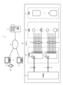
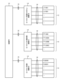
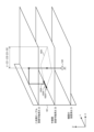
- FIG. 1 is an overall view showing an example of a plant design support system 1 and a plant 10;
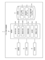
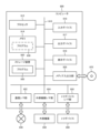
- FIG. 2 is a block diagram showing an example of a plant design support device 2;
- FIG. 2 is a data configuration diagram showing an example of a plant design database 5 and a design condition database 6;
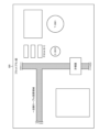
- FIG. 5 shows an example of a plot plan diagram 500.
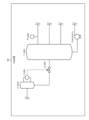
- FIG. FIG. 5 is a diagram showing an example of a P&ID diagram 501; 5 is a diagram showing an example of an I/O list 502;
- FIG. FIG. 5 is a diagram showing an example of a wiring block diagram 503;
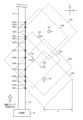
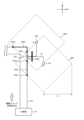
- FIG. 11 is a functional explanatory diagram showing a first processing example of repeater wiring design processing by a determining unit 202;
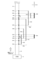
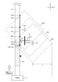
- FIG. 9 is a functional explanatory diagram (continuation of FIG. 8) showing the first processing example of repeater wiring design processing by the determining unit 202;
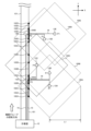
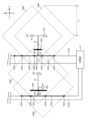
- FIG. 10 is a functional explanatory diagram (continuation of FIG. 9 ) showing the first processing example of repeater wiring design processing by the determining unit 202;
- FIG. 11 is a functional explanatory diagram showing a second processing example of repeater wiring design processing by the determining unit 202;
- 2 is a hardware configuration diagram showing an example of a computer 900 that constitutes the plant design support device 2 and the designer's terminal device 3.
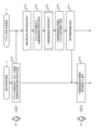
- FIG. 4 is a flow chart showing an example of the operation of the plant design support system 1;
- 14 is a flowchart (continuation of FIG. 13) showing an example of the operation of the plant design support system 1;
- FIG. 4 is a flow chart showing an example of the operation of the plant design support system 1;
- 14 is a flowchart (continuation of FIG. 13) showing an example of the operation of the plant design support
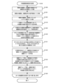
- FIG. 11 is a flow chart showing details of repeater wiring design processing (step S130) by the determination unit 202.
- FIG. FIG. 11 is a function explanatory diagram showing a first modification of repeater wiring design processing
- FIG. 11 is a function explanatory diagram showing a second modification of repeater wiring design processing
- FIG. 11 is a functional explanatory diagram showing a third modification of repeater wiring design processing
- FIG. 21 is a functional explanatory diagram showing a fourth modification of repeater wiring design processing
- FIG. 20 is a functional explanatory diagram showing a fifth modification of repeater wiring design processing
- FIG. 21 is a function explanatory diagram showing a sixth modification of repeater wiring design processing;
- FIG. 1 is an overall view showing an example of a plant design support system 1 and a plant 10.
- the plant design support system 1 functions as a system for supporting the design of the plant 10 , especially the wiring design of the repeaters 14 installed in the plant 10 .
- the plant 10 is, for example, any plant such as a natural gas plant, an oil refinery plant, a chemical processing plant, a power plant, a steel plant, etc., but is not limited to these examples.
- the plant 10 includes, for example, various facilities 11 for processing arbitrary fluids such as gases, liquids, and granules having fluidity, such as reaction towers, distillation towers, tanks, boilers, heating furnaces, and heat exchangers. , piping, etc. are installed to carry out the predetermined manufacturing process.
- the plant 10 includes a control room 12 that performs control of the manufacturing process, emergency shutdown, and safety monitoring of the plant 10, and a plurality of devices that transmit and receive various equipment signals (sensor signals and control signals) between the control room 12 and the control room 12. and a plurality of repeaters 14 connected between the control room 12 and the plurality of devices 13 to relay device signals.
- a process control system is a management system that controls the manufacturing process for producing products from raw materials.
- the emergency stop system is a management system that detects an abnormality in the facility 11 or the equipment 13 during execution of the manufacturing process and emergency stops the manufacturing process.
- the safety system is a management system that detects dangerous gas leaks, fires, etc., and activates evacuation warnings and fire extinguishing systems for workers.
- the device 13 measures the flow rate, pressure, temperature, liquid level, components, etc. of the fluid flowing through the facility 11, and receives an instrument such as a sensor that outputs a sensor signal indicating the measurement result, and a control signal. and controllers such as valves, pumps, compressors, etc. for controlling the flow rate, pressure, temperature, liquid level, composition, etc. of the fluid flowing through the facility 11 .
- the device 13 is not limited to the above example, and may include a part of the facility 11, may be an instrument for measuring physical quantities such as temperature and humidity in the surrounding environment of the facility 11, or may be a device for controlling those physical quantities. It may also include a controller for
- the instrument room 12 includes, for example, a control device (not shown) for each management system, receives a sensor signal (also referred to as an input signal) from the instrument 13 functioning as an instrument among the plurality of instruments 13, and the sensor signal indicates Based on the sensor information, a control signal (also referred to as an output signal) is transmitted to the device 13 functioning as a controller among the plurality of devices 13 .
- a plurality of control rooms 12 may be installed for one plant 10, or may be installed for each management system. Also, the controller may be shared by multiple management systems.
- the repeater 14 is, for example, a box-shaped electrical device called a junction box.
- the repeater 14 includes a primary side terminal 140 and a plurality of secondary side terminals 141 .
- a primary cable 15 connected to the instrument room 12 is connected to the primary terminal, and a secondary cable 16 connected to the device 13 is connected to the secondary terminal.
- the repeater 14 relays device signals transmitted and received between the instrument room 12 and the plurality of devices 13 by relaying the primary cable 15 and the secondary cable 16 .
- the repeater 14 has different specifications, such as the maximum number of secondary terminals 141 and whether it is an analog signal device or a digital signal device. 14 are used.
- the repeater 14 may be provided with a plurality of primary side terminals 140 .
- a multicore cable that transmits and receives multiple device signals is used.
- a single-core cable for transmitting and receiving a single device signal is basically used as the secondary cable 16, but a multi-core cable may be used.
- the single-core cable and the multi-core cable may use a set of two cores for one device signal.
- the primary side terminal 140 and the secondary side terminal 141 are a set of two terminals for one device signal.
- a value of 141 maximum signal connections (corresponding to half the maximum number of terminals) may be used. Therefore, when the maximum number of signals to be connected to the secondary side terminal 141 is 5 when using a single-core cable having a set of two cores, the physical number of the secondary side terminals 141 is 10. be prepared.
- the plant design support system 1 includes, as its main components, a plant design support device 2 that supports wiring design of a plurality of repeaters 14 installed in the plant 10, and a designer terminal device used by the designer of the plant 10. 3.
- the plant design support device 2 and the designer's terminal device 3 are configured by, for example, a general-purpose or dedicated computer (see FIG. 12 to be described later), and are connected to a wired or wireless network 4 to mutually exchange various data. Configured to be able to send and receive.
- the number of plant design support devices 2 and designer terminal devices 3 and the configuration of network 4 are not limited to the example in FIG.
- the plant design support device 2 is composed of, for example, a server-type computer or a cloud-type computer.
- the plant design support device 2 includes a plant design database 5 that manages plant design information 50 of each plant 10, and a design condition database 6 that manages design requirements, design procedures, design rules, etc. when designing each plant 10. Prepare.
- the plant design support device 2 cooperates with the designer's terminal device 3, and as part of the instrumentation design included in the detailed design, the configuration and operation when supporting the wiring design of the repeater 14 are mainly described.
- the plant design support device 2 and the designer terminal device 3 may support basic design and detailed design other than the wiring design of the repeater 14 in the overall design of the plant 10 .
- the designer terminal device 3 is composed of, for example, a stationary computer or a portable computer, and is used by the designer 30.
- the designer's terminal device 3 is installed with programs such as applications and browsers, receives various input operations, and outputs various information via a display screen and voice.
- the designer terminal device 3 transmits and receives various data to and from the plant design support device 2, for example, displaying the contents of the plant design database 5 and the design condition database 6 on the display screen, and displaying the contents on the display screen. receives various input operations, registers new data in the plant design database 5 and the design condition database 6, and corrects registered data, thereby supporting the wiring design of the repeater 14. .
- FIG. 2 is a block diagram showing an example of the plant design support device 2.
- the plant design support device 2 includes a control unit 20 configured by a processor or the like, a storage unit 21 configured by an HDD, an SSD, a memory, or the like, a communication unit 22 as a communication interface with the network 4, a keyboard, a mouse, and the like. and a display unit 24 configured by a display or the like. Note that the input unit 23 and the display unit 24 may be omitted.
- the storage unit 21 stores the plant design database 5, the design condition database 6, and the plant design support program 210, as well as the operating system, other programs, various data, and the like.
- the control unit 20 functions as an instruction reception unit 200, an information acquisition unit 201, a determination unit 202, and an information output unit 203 by executing the plant design support program 210 stored in the storage unit 21.
- FIG. 3 is a data configuration diagram showing an example of the plant design database 5 and the design condition database 6.
- the plant design database 5 consists of plant design information 50, which is design data of each plant 10 (plants A, B, . . . , N in the example of FIG. 3), and parts master information 51 referenced by the plant design information 50 Configured.
- the plant design information 50 is generated by the design work of the plant 10, and includes, for example, a plot plan diagram 500, a P&ID diagram (Piping & Instrument Diagram) 501, an I/O (input/output) list 502, a wiring block diagram 503, wiring It is composed of the blueprint 504 and the like.
- the plot plan diagram 500, P&ID diagram 501, I/O list 502, wiring block diagram 503, and wiring design diagram 504 may be generated for each management system or each floor area, for example.
- the equipment 11, the equipment 13, the repeater 14, the primary cable 15, and the secondary cable 16 installed in the plant 10 have, for example, unique equipment IDs, equipment IDs, repeater IDs, and cable IDs. identification number, identification code, identification name, identification tag, etc. (numbers, characters, or a combination thereof).
- the information between each data is linked
- the equipment 11, the equipment 13, the repeater 14, the primary cable 15, and the secondary cable 16 are assigned component IDs managed by the component master information 51, respectively. By referring to the master information 51, specifications of the facility 11, the device 13, the repeater 14, the primary cable 15, and the secondary cable 16 are specified.
- FIG. 4 is a diagram showing an example of a plot plan diagram 500.
- FIG. The plot plan diagram 500 is data recording a layout diagram of the plant 10 .
- the installation position (X coordinate, Y coordinate) and installation height (Z coordinate) of the equipment 11 the installation position (X coordinate, Y coordinate) of the control room 12, and the primary cable 15 are installed.
- Primary cable installation area indicating possible area
- repeater installation height (Z coordinate) indicating height at which repeater 14 can be installed
- secondary cable indicating height at which secondary cable 16 can be installed
- the installable height (Z coordinate) and the like are recorded.
- the primary-side cable installation area is, for example, an area where a cable duct for the primary-side cable 15 is installed.
- a cable duct any method such as a ceiling-embedded method, a ceiling-suspended method, a floor groove method, an under-floor method, or the like can be used.
- the repeater installable height is, for example, the height from the floor when the repeater 14 is installed, and may have a predetermined range.
- the height at which the secondary cable can be installed is, for example, the height from the floor when the secondary cable 16 is wired, and is specified by, for example, the height of the ceiling.
- FIG. 5 is a diagram showing an example of a P&ID diagram 501.
- FIG. The P&ID diagram 501 is data recording the flow of the manufacturing process, the layout relationship and the physical connection relationship of the facility 11 and the equipment 13 .
- FIG. 6 is a diagram showing an example of the I/O list 502.
- the I/O list 502 is data in which attributes of device signals transmitted and received from the device 13 are recorded, for example, in tabular form.
- the I/O list 502 records the device ID, signal type, system type, installation position (X coordinate, Y coordinate), installation height (Z coordinate), etc. as attributes of the device signal.
- the signal type is information specifying whether the signal is an analog signal or a digital signal.
- the system type is information specifying which of the plurality of management systems (in this embodiment, the process control system, the emergency stop system, and the safety system) operating in the plant 10, the device is used in which management system. is.
- the installation position and installation height of each equipment 13 in the I/O list 502 can be determined from the P&ID diagram 501 to determine the arrangement relationship and physical physical
- the result obtained by specifying the connection relationship and further specifying the installation position and installation height of each facility 11 from the plot plan diagram 500 is recorded. Note that the installation position and installation height of each device 13 may be recorded in the plot plan diagram 500 or other data. may be omitted.
- FIG. 7 is a diagram showing an example of the wiring block diagram 503.
- the wiring block diagram 503 is data recording electrical connection relationships among the control room 12 , the equipment 13 , the repeater 14 , the primary cable 15 , and the secondary cable 16 .
- the wiring block diagram 503 records the installation specifications of the repeater 14 and the allocation of the devices 13 connected to the repeater 14 by designing the wiring of the repeater 14 .
- the allocation of the devices 13 is information specifying the devices 13 connected to the plurality of secondary terminals 141 via the secondary cables 16 .
- the installation specification of the repeater 14 is, for example, information that specifies the specification of the repeater 14 by allocating a part ID and referring to the part master information using the part ID.
- the wiring design diagram 504 is a layout diagram relating to the wiring design of the repeater 14, and is data recording a layout diagram that can be layered (superimposed) on the plot plan diagram 500, for example.
- the installation position (X coordinate, Y coordinate) of the repeater 14, the route of the primary side cable 15, the route of the secondary side cable 16, etc. are recorded by performing the wiring design of the repeater 14. be done.
- Some or all of the data recorded in the wiring design drawing 504 may be recorded in the plot plan drawing 500 or other data.
- the parts master information 51 is data for managing various parts such as the equipment 11, the equipment 13, the repeater 14, the primary cable 15, the secondary cable 16, and the like.
- the part master information 51 has a record for each part, and has fields in which, for example, part ID, name, major classification, minor classification, specification, size, etc. can be registered.
- the design condition database 6 is data recording design requirements, design procedures, design rules, etc. when designing each plant 10, and is composed of repeater wiring design conditions 60 relating to repeater wiring design.
- the secondary cable upper limit length, terminal spare allowable value, etc. are recorded.
- the secondary cable upper limit length is information indicating the upper limit of the length of the secondary cable 16 .
- the terminal spare allowable value is information indicating the allowable value of the spare ratio or number of spares of the secondary terminal 141 of the repeater 14 to which the secondary cable 16 is connected.
- the repeater wiring design condition 60 is not limited to the above example, and may include, for example, the upper limit of the number of repeaters 14 to be installed, specifications of installable repeaters 14, and the like. Further, the repeater wiring design conditions 60 may be separately prepared for each plant 10 or may be shared by a plurality of plants 10 .
- the plant design database 5 and the design condition database 6 are referenced by the designer terminal device 3, and editing operations such as addition, deletion, and correction of each data are performed by the designer 30 on the display screen of the designer terminal device 3. .
- authority control is performed according to the permission authority possessed by each designer.
- the plant design database 5 and the design condition database 6 cooperate with the CAD system, and each data (for example, parts master information 51, etc.) is updated as needed.
- the data configurations of the plant design database 5 and the design condition database 6 are not limited to the above examples, and may be changed as appropriate. Some of the above data may be omitted, or data other than the above may be added. may Also, the plant design database 5 and the design condition database 6 can adopt any data format, for example, XML format, CAD format, or a combination of multiple data formats.
- the instruction receiving unit 200 transmits display screen information for displaying various display screens to the designer terminal device 3, and receives an input operation by the designer 30 via the display screen. It functions as a user interface with the designer 30 who designs wiring.
- the instruction receiving unit 200 receives, for example, an instruction to select the plant 10 that is the target of the wiring design of the repeater 14, an instruction to execute the repeater wiring design process for determining the installation position of the repeater 14, the allocation of the devices 13, and the like. .
- the repeater wiring design process is executed by the determination unit 202, which will be described later.
- the instruction receiving section 200 functions as a correction receiving section 200A and an update receiving section 200B.
- the correction accepting unit 200A accepts a correction instruction for correcting a part of information of at least one of the installation position of the repeater 14 and the allocation of the device 13 determined in the repeater wiring design process.
- the update reception unit 200B receives an update instruction to update a part of at least one of the plant design information 50 and the repeater wiring design conditions 60, the installation position of the repeater 14 determined in the repeater wiring design process, and the A change prohibition instruction specifying a change prohibition range in which change of information in at least one of the allocations of the device 13 is prohibited is accepted.
- the information acquisition unit 201 acquires the installation position of the control room 12, the installation position of the equipment 13, and the primary cable installation area in the layout plan of the plant 10 from the plant design information 50. to get as At that time, the information acquisition unit 201, for example, by analyzing the plot plan diagram 500 and the P&ID diagram 501 included in the plant design information 50, from the P&ID diagram 501, the arrangement relationship and physical connection relationship of the equipment 11 and the equipment 13 and further specify the installation position and installation height of each equipment 11 from the plot plan diagram 500 to acquire the installation position and installation height of each equipment 13, and the acquired result is It may be recorded in the I/O list 502 .
- the information acquisition unit 201 may acquire data other than the above as long as the data is included in the plant design information 50.
- the installation height of the equipment 13, the repeater installable height, The height at which the secondary cable can be installed may be further acquired, and the attribute of the device signal may be further acquired.
- the information acquisition unit 201 acquires the repeater wiring design conditions 60 by referring to the design condition database 6, for example.
- the information acquisition unit 201 acquires, for example, the secondary cable upper limit length and the terminal spare allowable value as the repeater wiring design conditions 60 .
- Part or all of the plant design database 5 or part or all of the design condition database 6 may be stored in an external device (or a plurality of devices) connectable to the network 4, in which case , the information acquisition unit 201 may acquire the plant design information 50 and the repeater wiring design conditions 60 from the external device via the network 4 and the communication unit 22 .
- Part or all of the plant design database 5 or part or all of the design condition database 6 may be stored in any storage medium. You may acquire the plant design information 50 and the repeater wiring design conditions 60 from media (a plurality may be sufficient).
- the determination unit 202 determines the installation position of the repeater 14 in the layout plan and the equipment 13 connected to the repeater 14. Repeater wiring design processing for determining assignment is performed.
- the determination unit 202 determines the secondary cable upper limit based on the installation position of the device 13 in the layout drawing of the plant 10.
- a virtual frame defined by the length L1 is arranged for each device 13, and an intersection line segment connecting the intersections of the outline of the primary cable installation area and the virtual frame is generated for each device 13, and the control room 12 is generated.
- the equipment 13 corresponding to the intersecting line segments including the overlapping line segments is specified as a device group, and for each device group, the overlapping line segments are identified.
- the installation position of the repeater 14 is determined inside the line segment, and the allocation of the device 13 is determined assuming that the device 13 corresponding to the intersecting line segment including the overlapping line segment is connected to the repeater 14 .
- FIG. 8 to 10 are functional explanatory diagrams showing a first processing example of repeater wiring design processing by the determining unit 202.
- FIG. 8 to 10 for simplification of explanation, repeater wiring design processing in a situation where five devices 13A to 13E are installed as the device 13 will be described.
- the determination unit 202 determines the virtual length defined by the secondary cable upper limit length L1 with reference to the installation positions P1 (white circles) of the devices 13A to 13E in the layout plan of the plant 10.
- Frames 100A to 100E (dashed lines) are arranged for each of the devices 13A to 13E.
- the shape of the virtual frames 100A to 100E is a rhombus. It is defined as the upper limit length L1.
- the reason for adopting the rhombus is that, assuming that the secondary cable 16 is routed along the X and Y directions, the upper limit length of the secondary cable is set around the installation position P1 of the devices 13A to 13E.
- the reachable range of the secondary cable 16 having L1 is diamond-shaped.
- the shape of the virtual frame 100 may be, for example, another shape such as a circle.
- the radius of the circle may be defined by the secondary cable upper limit length L1.
- the determination unit 202 identifies two intersections 102A to 102E (black circles) where the outline 101 of the primary cable installation area and the virtual frames 100A to 100E intersect, and connects the two intersections 102A to 102E. Intersecting line segments 103A-103E are generated for each of the devices 13A-13E. In FIG. 9, five intersecting line segments 103A to 103E are shown shifted for ease of explanation.
- the determining unit 202 searches for overlapping line segments 104A and 104B where the intersecting line segments 103A to 103E for each of the devices 13A to 13E overlap with the control room 12 as a starting point.
- devices 13A to 13E corresponding to intersecting line segments 103A to 103E including overlapping line segments 104A and 104B are identified as device groups 105A and 105B.
- the determination unit 202 sets the search direction for the device groups 105A and 105B to the direction away from the control room 12 starting from the control room 12, and proceeds to search for the overlapping line segments 104A and 104B.
- the device groups 105A and 105B are identified sequentially. In the example of FIG.
- three devices 13A to 13C corresponding to three intersecting line segments 103A to 103C including the first overlapping line segment 104A are found.
- the two equipments 13D, 13E corresponding to the two intersecting segments 103D, 103E identified as the first equipment group 105A and containing the second overlapping line segment 104B are identified as the second equipment group 105B.
- the determining unit 202 may identify the device group by searching for the overlapping line segments so that the number of devices 13 corresponding to the intersection line segment including the overlapping line segment satisfies the terminal spare allowance. good.
- the maximum number of terminals (or the maximum number of signal connections) of the secondary side terminals 141 is 5 points, and the terminal spare allowance is 50% of the spare rate.
- the number of spares is three, two devices 13A and 13B are identified as the first device group, two devices 13C and 13D are identified as the second device group, and one device 13E is identified as the third device group. device group.
- the determination unit 202 creates the first and second device groups 105A and 105B inside the first and second overlapping line segments 104A and 104B for each of the first and second device groups 105A and 105B.
- the installation positions P2 of the repeaters 14A and 14B are respectively determined, and the three devices 13A to 13C corresponding to the three intersecting segments 103A to 103C including the first overlapping segment 104A are connected to the first repeater 14A.
- the five devices 13A to 13E are allocated as follows: decide.
- the installation position P2 of the first and second repeaters 14A, 14B is described as being determined at the midpoint of the first and second overlapping line segments 104A, 104B. Any other position may be determined as long as it is inside the .
- the determining unit 202 may determine the installation specifications of the repeaters 14 so that the number of the devices 13 corresponding to the intersecting line segments including the overlapping line segments satisfies the terminal spare allowable value for each device group. good.
- the maximum number of terminals (or the maximum number of signal connections) of the secondary side terminal 141 is 5 points and 10 points.
- the terminal spare allowance is a spare rate of 50% or the number of spares is 3
- the number of devices 13A to 13C included in the first device group 105A is three.
- the installation specification of the repeater 14 is determined to have a maximum number of 10 secondary terminals 141, and the number of devices 13D and 13E included in the second device group 105B is two.
- the installation specification of the repeater 14 for the second device group 105B is determined such that the maximum number of secondary terminals 141 is five.
- the determination unit 202 performs the repeater wiring design process.
- the upper limit length of the secondary side cable L1 may be arranged for each device 13 .
- FIG. 11 is a functional explanatory diagram showing a second processing example of repeater wiring design processing by the determining unit 202.
- the second processing example differs from the first processing example in that the length of the secondary cable 16 is taken into account in the height direction (Z direction), and other processing contents are common. Note that FIG. 11 illustrates the virtual frame 100A for one device 13A.
- the center is the installation position P1 of the device 13, and the distance from the center to each point is the installation height of the device 13 from the secondary cable upper limit length L1.
- the difference between Z1 and secondary cable installation height Z3 (
- ) and the difference between repeater installation height Z2 and secondary cable installation height Z3 (
- the determination unit 202 may determine the installation position of the repeater 14 and the allocation of the device 13 for each attribute of the signal.
- the determination unit 202 determines the installation position of the repeater 14 and the allocation of the device 13 for each management system.
- the installation position of the repeater 14 for the process control system and the process for the repeater 14 Determine the allocation of the equipment 13 used in the control system, determine the installation position of the repeater 14 for the emergency stop system, determine the allocation of the equipment 13 used in the emergency stop system to the repeater 14, and determine the allocation of the equipment 13 used in the emergency stop system.
- the installation position of the repeater 14 and the assignment of the equipment 13 used in the safety system to the repeater 14 are determined.
- the determination unit 202 determines the installation positions of the repeaters 14 and the allocation of the devices 13 for each signal type. In this embodiment, by separately installing the repeater 14 for digital signals and for analog signals, the installation position of the repeater 14 for digital signals and the equipment for transmitting and receiving digital signals to the repeater 14 13 are determined, and the installation position of the analog signal repeater 14 and the allocation of the analog signal transmission/reception device 13 to the repeater 14 are determined.
- the determination unit 202 may determine the route of the primary cable 15 and the route of the secondary cable 16. For example, the determination unit 202 determines the route of the primary cable 15 by searching for a route that connects the installation position of the instrument room 12 and the installation position of the repeater 14 so as to pass through the primary cable installation area. do. The determining unit 202 searches for the route of the secondary cable 16 connecting the installation position of the repeater 14 and the device 13 connected to the repeater 14 so as to satisfy the secondary cable installation height. , determine the route of the secondary cable 16 .
- the determining unit 202 corrects the installation position of the repeater 14 and the allocation of the device 13 based on the correction instruction.
- the installation positions of the repeaters 14 and the allocation of the devices 13 determined by the determination unit 202 can be tentatively determined, and final determination can be made in a state in which correction instructions from the designer 30 are reflected.
- the correction instruction may further correct any of the installation specifications of the repeater 14, the route of the primary cable 15, and the route of the secondary cable 16. In that case, based on the correction instruction, That information will be corrected.
- the determining unit 202 determines the The installation positions of the relays 14 and the allocation of the devices 13 that do not fall within the change-prohibited range specified by the change-prohibited instruction are re-determined. As a result, after the installation position of the repeater 14 and the allocation of the devices 13 are determined by the determining unit 202, for example, when design changes such as addition, deletion, and change of the devices 13 are made, the wiring of the repeater 14 can be changed. Rather than redoing the entire design, by limiting the target of redoing only to the portions that do not fall under the change-prohibited range, it is possible to suppress the range of influence of the design change.
- the information output unit 203 registers the repeater wiring design information (for example, the installation position and installation specifications of the repeater 14, the allocation of the equipment 13, etc.) determined by the repeater wiring design processing by the determination unit 202 in the plant design information 50. do. Specifically, the information output unit 203 registers the installation position of the repeater 14 , the route of the primary cable 15 , and the route of the secondary cable 16 in the wiring design drawing 504 . The information output unit 203 also registers the installation specifications of the repeater 14 and the allocation of the devices 13 connected to the repeater 14 in the wiring block diagram 503 . Note that the registration destination of the repeater wiring design information for the plant design information 50 is not limited to the above example.
- the information output unit 203 transmits display screen information for displaying the repeater wiring design information as a display screen to the designer terminal device 3, and prompts the designer 30 to check the information through the display screen. good too. Then, through the display screen, the correction receiving section 200A may receive the correction instruction, or the update receiving section 200B may receive the update instruction and the change prohibition instruction.
- FIG. 12 is a hardware configuration diagram showing an example of a computer 900 that constitutes the plant design support device 2 and the designer's terminal device 3. As shown in FIG.
- Each of the plant design support device 2 and the designer's terminal device 3 is composed of a general-purpose or dedicated computer 900 .
- the computer 900 includes, as its main components, a bus 910, a processor 912, a memory 914, an input device 916, an output device 917, a display device 918, a storage device 920, a communication I/F (interface). It has a section 922 , an external equipment I/F section 924 , an I/O (input/output) device I/F section 926 and a media input/output section 928 . Note that the above components may be omitted as appropriate depending on the application for which the computer 900 is used.
- the processor 912 is composed of one or more arithmetic processing units (CPU (Central Processing Unit), MPU (Micro-processing unit), DSP (digital signal processor), GPU (Graphics Processing Unit), etc.), and the entire computer 900 It operates as a control unit that supervises the
- the memory 914 stores various data and programs 930, and is composed of, for example, a volatile memory (DRAM, SRAM, etc.) functioning as a main memory, a non-volatile memory (ROM), a flash memory, and the like.
- the input device 916 is composed of, for example, a keyboard, mouse, numeric keypad, electronic pen, etc., and functions as an input unit.
- the output device 917 is configured by, for example, a sound (voice) output device, a vibration device, or the like, and functions as an output unit.
- a display device 918 is configured by, for example, a liquid crystal display, an organic EL display, electronic paper, a projector, or the like, and functions as an output unit.
- the input device 916 and the display device 918 may be configured integrally like a touch panel display.
- the storage device 920 is composed of, for example, an HDD, SSD, etc., and functions as a storage unit. The storage device 920 stores various data necessary for executing the operating system and programs 930 .
- the communication I/F unit 922 is connected to a network 940 (which may be the same as the network 4 in FIG. 1) such as the Internet or an intranet by wire or wirelessly, and exchanges data with other computers according to a predetermined communication standard. functions as a communication unit that transmits and receives.
- the external device I/F unit 924 is connected to the external device 950 such as a camera, printer, scanner, reader/writer, etc. by wire or wirelessly, and serves as a communication unit that transmits and receives data to and from the external device 950 according to a predetermined communication standard. Function.
- the I/O device I/F unit 926 is connected to I/O devices 960 such as various sensors and actuators, and exchanges with the I/O devices 960, for example, detection signals from sensors and control signals to actuators. functions as a communication unit that transmits and receives various signals and data.
- the media input/output unit 928 includes, for example, a drive device such as a DVD (Digital Versatile Disc) drive and a CD (Compact Disc) drive, a memory card slot, and a USB connector. Data is read from and written to (non-temporary storage medium) 970 .
- the processor 912 calls the program 930 stored in the storage device 920 to the memory 914 and executes it, and controls each part of the computer 900 via the bus 910 .
- the program 930 may be stored in the memory 914 instead of the storage device 920 .
- the program 930 may be recorded on the media 970 in an installable file format or executable file format and provided to the computer 900 via the media input/output unit 928 .
- Program 930 may be provided to computer 900 by downloading via network 940 via communication I/F section 922 .
- the computer 900 may implement various functions realized by the processor 912 executing the program 930 by hardware such as FPGA (field-programmable gate array), ASIC (application specific integrated circuit), or the like. good.
- the computer 900 is, for example, a stationary computer or a portable computer, and is an arbitrary form of electronic equipment.
- the computer 900 may be a client-type computer, a server-type computer, or a cloud-type computer.
- FIG. 13 and 14 are flowcharts showing an example of the operation of the plant design support system 1.
- FIG. In the following description, it is assumed that the information in the plant design database 5 and the design condition database 6 has been registered in advance.
- step S100 the designer terminal device 3 receives, for example, an input operation performed by the designer 30 on the display screen, an instruction to select the plant 10 to be the wiring design target of the repeater 14, and an instruction to select the relay.
- instruction information relating to the selection instruction and the execution instruction is sent to the plant design support device 2 .
- step S110 the instruction receiving unit 200 of the plant design support device 2 receives the instruction information, thereby accepting selection instructions and execution instructions.
- step S120 the information acquisition unit 201 refers to the plant design database 5 and the design condition database 6, and obtains the plant design information 50 and the repeater wiring design related to the selection instruction and the execution instruction received in step S110. Get condition 60 .
- the determining unit 202 performs repeater wiring design processing based on the plant design information 50 and the repeater wiring design conditions 60 acquired at step S120.
- FIG. 15 is a flowchart showing the details of the repeater wiring design process (step S130) by the determining unit 202.
- step S1300 the determination unit 202 classifies the plurality of devices 13 by the control room 12 to which each device 13 is connected. Note that if there is only one instrument room 12, step S131 is omitted.
- step S1301 the plurality of devices 13 are classified according to the signal type (analog signal or digital signal) of the device signal. system, emergency stop system, or security system).
- the repeater wiring design condition 60 if a design request that cannot be assigned to the same repeater 14 is further defined, a step of classifying the plurality of devices 13 based on the design request is further included. may be added.
- a duct side (corresponding to the outline 101 in FIGS. 8 to 10) on which the repeater 14 can be installed is specified in the primary cable installation area.
- the position of the duct side may be received from the designer's terminal device 3 as an input operation of the designer 30 .
- step S1320 the determination unit 202 sequentially selects a device group to be processed from the plurality of device groups classified in steps S1300 to S1302, and performs loop processing that repeats steps S1330 to S1334. For each device group, the installation position and installation specifications of the repeater 14 and the allocation of the devices 13 connected to the repeater 14 are determined.
- the first processing example see FIGS. 8 to 10
- the second processing example may be applied.
- step S1330 the determination unit 202 determines the secondary cable upper limit length with respect to the layout plan of the plant 10 based on the installation position P1 of the equipment 13 included in the equipment group to be processed.
- a diamond-shaped virtual frame 100 (100A to 100E) defined by the height L1 is arranged for each device .
- step S1331 the determination unit 202 identifies two intersections 102 (102A to 102E) where the outline 101 corresponding to the duct side in the primary cable installation area and the virtual frame 100 intersect.
- An intersection line segment 103 (103A to 103E) connecting two intersections 102 is generated for each device 13.
- step S1332 the determination unit 202 determines overlapping line segments 104 (104A, 104B) in which the intersection line segments 103 for each device 13 overlap, starting from the control room 12, as shown in FIG. , the device 13 corresponding to the intersecting line segment 103 including the overlapping line segment 104 is identified as the device group 105 (105A, 105B).
- step S1333 the determining unit 202 places the repeater 14 inside the overlapping line segment 104 (in this embodiment, the middle point of the overlapping line segment 104) for each device group 105, as shown in FIG. is determined, and the allocation of the devices 13 is determined assuming that the devices 13 corresponding to the intersecting line segments 103 including the overlapped line segment 104 are connected to the repeater 14 .
- step S1334 the determination unit 202 determines the number of repeaters 14 so that the number of devices 13 corresponding to the intersecting line segment 103 including the overlapping line segment 104 satisfies the terminal spare allowable value for each device group 105. Determine installation specifications for
- step S1320 by performing the loop processing in step S1320, the installation position and installation specification of each repeater 14, and the installation specifications of each repeater 14 for each device group classified by each control room, each signal type, and each system type. , and the series of repeater wiring design processing shown in FIG. 15 is completed.
- step S140 shown in FIG. 13 the information output unit 203 outputs the repeater wiring design information (for example, the installation position and installation specifications of the repeater 14, the ) are registered in the plant design information 50. Then, in step S141, the information output unit 203 transmits display screen information for displaying the repeater wiring design information as a display screen to the designer's terminal device 3.
- the information output unit 203 outputs the total number of the repeaters 14 installed, the total number of the primary side cables 15 and the secondary side cables 16, the lengths of the primary side cables 15 and the secondary side cables 16, each A total value obtained by summing the cable lengths may be calculated, and the calculated result may be included in the repeater wiring design information and the display screen information.
- step S150 upon receiving the display screen information, the designer terminal device 3 displays the repeater wiring design information on the display screen based on the display screen information.
- step S160 shown in FIG. 14 as an input operation of the designer 30 who has confirmed the repeater wiring design information, part of the information of at least one of the installation position of the repeater 14 and the allocation of the device 13 is corrected.
- the correction reception unit 200A receives the correction instruction in step S161.
- the determination unit 202 corrects the installation position of the repeater 14 and the allocation of the device 13 based on the correction instruction.
- the corrected repeater wiring design information is registered in the plant design information 50 by the information output unit 203 in the same manner as in step S140.
- step S170 as an input operation of the designer 30 who has confirmed the repeater wiring design information, an update instruction to update a part of at least one of the plant design information 50 and the repeater wiring design conditions 60;
- the update reception unit 200B receives the update instruction and the change prohibition instruction.
- the determining unit 202 based on the update instruction and the change prohibition instruction, based on the updated plant design information 50 and the repeater wiring design conditions 60, determines the change prohibition specified by the change prohibition instruction.
- the installation positions of repeaters 14 that do not fall within the range and the allocation of devices 13 are determined again.
- the re-determined repeater wiring design information is registered in the plant design information 50 by the information output section 203 in the same manner as in step S140. Furthermore, display screen information for displaying the re-determined repeater wiring design information as a display screen may be transmitted to the designer's terminal device 3 by the information output unit 203, as in step S141.
- steps S110, S161, and S171 correspond to an instruction receiving step
- step S120 corresponds to an information acquisition step
- steps S130, S162, and S172 correspond to a determination step
- step S140 corresponds to an information output step.
- the determination unit 202 determines the installation position of the repeater 14 in the layout drawing and the connection to the repeater 14 based on the plant design information 50 and the repeater wiring design conditions 60. Therefore, it is possible to properly design the wiring of the repeater 14 without requiring extensive site construction experience or advanced design skills.
- each part provided in the plant design support device 2 has been described as being realized by one device, but the function of each part is distributed to a plurality of devices so that it can be realized by a plurality of devices. good too.
- the controller of the designer's terminal device 3 may function as the plant design support device 2 by executing the plant design support program 210 .
- the plant design support system 1 operates according to the flowcharts shown in FIGS. may
- the plant design support device 2 is described as performing the repeater wiring design process for one repeater wiring design condition 60, but a plurality of repeater wiring design conditions 60 (for example, the secondary side
- the repeater wiring design process may be performed for each of the cable upper limit lengths and terminal spare allowable values).
- the plant design support device 2 may output a plurality of pieces of repeater wiring design information respectively determined in the repeater wiring design process to the designer 30, and the designer 30 may compare and study.
- the plant design support device 2 uses a plurality of repeater wiring design information determined in the repeater wiring design process according to a predetermined standard (total number of repeaters 14 installed, primary cable 15 and secondary cable 15). The total number of side cables 16, the length of each cable, the total value of each cable length, etc.) may be compared to output optimum repeater wiring design information.
- step S130 the details of the repeater wiring design process (step S130) by the determination unit 202 have been described, but the process contents may be changed as appropriate. First to sixth modifications of the repeater wiring design process will be described below.
- FIG. 16 is a functional explanatory diagram showing a first modified example of repeater wiring design processing.
- the determination unit 202 connects the two intersections 102 where the outline 101 of the primary cable installation area and the virtual frame 100 intersect, thereby forming the intersection line segment 103 into the device. 13, intersecting line segments 103F and 103G are generated along the outline 101 of the primary cable installation area, like the devices 13F and 13G shown in FIG. Therefore, the intersection line segment 103G for the device 13G is generated in a polygonal line shape by connecting two intersections 102G along the corners of the outline 101, as shown in FIG.
- the intersecting line segment 103 may be generated in a curved shape.
- the overlapping line segment 104C is generated in a straight line. It may be generated in a polygonal line shape or a curved shape.
- FIG. 17 is a functional explanatory diagram showing a second modified example of repeater wiring design processing.
- the intersection line segment 103 is generated by connecting the two intersection points 102 where the outline 101 of the primary cable installation area and the virtual frame 100 intersect. .
- the intersection line segment 103 connects the intersection points (same side intersection points) where the outline 101 of the primary cable installation area located on the same side as the device 13 and the imaginary frame 100 intersect.
- the device 13 may be generated on the same side, or the device 13 may be generated by connecting the intersection points (opposite side intersections) where the outline 101 of the primary cable installation area located on the opposite side of the device 13 and the virtual frame 100 intersect. and may be generated on the opposite side.
- the installation position P2 of the repeater 14 may be determined on the same side of the equipment 13 as the primary cable installation area, or may be determined on the opposite side of the equipment 13 from the primary cable installation area.
- the intermediate device connection setting indicating whether or not to allow the device 13 to be connected to the repeater 14 located on the opposite side of the primary cable installation area with respect to the device 13 It is recorded in the wiring design condition 60. Then, if the intermediate device connection setting permits connection to the opposite side of the primary cable installation area, the determining unit 202 determines whether the device 13 is connected to the same side or the opposite side of the primary cable installation area. The installation position of the repeater 14 and the allocation of the device 13 are determined so as to be connected to the repeater 14 located.
- the determination unit 202 selects a relay located on the same side of the primary-side cable installation area with respect to the device 13 .
- the installation position of the repeater 14 and the allocation of the device 13 are determined so that the repeater 14 is connected only to the device 14 .
- the determining unit 202 is located on the opposite side of the device 13J as shown in FIG.
- an intersection line segment 103J is generated on the opposite side of the device 13J.
- the device 13J is assigned to be connected to the repeater 14D located on the opposite side of the primary cable installation area, as shown in FIG.
- the secondary cable 16 for the device 13J is installed across the primary cable installation area. Therefore, the number of installed repeaters 14 can be reduced.
- FIG. 18 is a functional explanatory diagram showing a third modified example of repeater wiring design processing.
- the determination unit 202 determines the installation position P2 of the repeater 14 inside the overlapping line segment 104 for each device group 105 in step S1333, the plurality of devices included in the device group 105
- the installation position P2 of the repeater 14 is determined based on the total value of the lengths of the secondary cables 16 when the cables 13 are connected to the repeater 14 respectively. Therefore, the installation position P2 of the repeater 14E with respect to the devices 13A to 13C shown in FIG. be done.
- the determining unit 202 may determine the installation position P2 of the repeater 14 so that the total value of the cable lengths of the secondary cables 16 becomes short.
- the determination unit 202 may determine the installation position P2 of the repeater 14 so that the total value is the minimum value.
- the installation position P2 of the repeater 14 is determined in consideration of the total length of each cable of the secondary cable 16 . Therefore, it is possible to reduce the overall usage of the secondary cable 16 .
- FIG. 19 is a functional explanatory diagram showing a fourth modified example of repeater wiring design processing.
- a repeater installation prohibited area 106 indicating an area where installation of the repeater 14 is prohibited in the primary cable installation area is recorded in the plot plan diagram 500, for example.
- the determining unit 202 determines the installation position P2 of the repeater 14 with respect to the primary cable installation area excluding the repeater installation prohibited area 106 .
- step S1331 when the determination unit 202 generates the intersecting line segment 103 for each device 13, as shown in FIG. Two intersections 102K-102M where the outline 101 intersects with the virtual frames 100K-100M are specified, and intersection line segments 103K-103M connecting the two intersections 102K-102M are generated.
- intersection segments 103K and 103L for devices 13K and 13L are generated limited to ends (intersection points 102K and 102L) of repeater installation prohibited area 106 .
- the overlapping line segment 104G that overlaps the intersecting line segments 103K and 103L is searched so as not to include the repeater installation prohibited area 106 as shown in FIG. It is determined by avoiding the repeater installation prohibited area 106 . Therefore, for example, by treating an area where the primary cable 15 is buried underground as the repeater installation prohibited area 106, the installation position P2 of the repeater 14 is determined in such a repeater installation prohibited area 106. can be prevented.
- FIG. 20 is a functional explanatory diagram showing a fifth modified example of repeater wiring design processing.
- the determination unit 202 determines the installation position P2 of the repeater 14 and the allocation of the device 13 for each attribute of the signal.
- installable signal attributes that indicate attributes of signals that can be installed for the primary cable installation area are recorded, for example, in plot plan diagram 500 .
- the determining unit 202 sets the repeater so that the primary cable 15 corresponding to the signal attribute indicated by the installable signal attribute set for the primary cable installation area is installed in the primary cable installation area. 14 and the allocation of the devices 13 are determined.
- the determination unit 202 determines the process control system
- the installation position P2 of the repeater 14H with respect to the process control system is determined so that the devices 13N and 13P used in . and.
- the determining unit 202 determines whether the devices 13Q and 13R used in the emergency stop system are connected by the secondary cable 16 to the primary cable installation area (outline 101B) in which the emergency stop system is set as the installable signal attribute.
- the installation position P2 of the repeater 14I with respect to the emergency stop system is determined.
- the determination unit 202 selects the digital signal for the primary cable installation area (outline 101A) in which the digital signal is set as the installable signal attribute.
- the installation position P2 of the digital signal repeater 14H is determined so that the devices 13N and 13P for transmission and reception are connected by the secondary cable 16.
- the determining unit 202 determines that the devices 13Q and 13R for transmitting and receiving analog signals are connected by the secondary cable 16 to the primary cable installation area (outline 101A) in which analog signal use is set as the installable signal attribute.
- the installation position P2 of the analog signal repeater 14I is determined.
- the primary cable 15 is installed so that the installation position P2 of the repeater 14 and the allocation of the device 13 correspond to the specific signal attribute set in the installation possible signal attribute for the primary cable installation area. is determined as Therefore, it is not possible to install a repeater 14 or assign a device 13 corresponding to a signal attribute different from the installable signal attribute to the primary cable installation area in which the installable signal attribute is set. can be prevented.
- FIG. 21 is a functional explanatory diagram showing a sixth modification of the repeater wiring design process.
- a secondary cable installation prohibited area 107 indicating an area where installation of the secondary cable 16 is prohibited is recorded in the plot plan diagram 500, for example.
- the determination unit 202 determines the installation position P2 of the repeater 14 so that the secondary cable 16 does not pass through the secondary cable installation prohibited area 107 .
- step S1331 when the determination unit 202 generates the intersecting line segment 103 for each device 13, when the secondary cable 16 is installed in the intersecting line segment 103, the secondary cable installation Intersecting line segments 103S to 103V are generated by excluding line segments passing through the prohibited area 107.
- FIG. 21 the intersection line segment 103U with respect to the device 13U is limited to the end (intersection point 102U) of the secondary cable installation prohibited area 107.
- the overlapping line segment 104K that overlaps the intersecting line segment 103U is searched so as not to overlap the secondary cable installation prohibited area 107 as shown in FIG.
- a route for installation is determined while avoiding the secondary cable installation prohibited area 107 . Therefore, for example, the two repeaters 14 are connected separately so that there is an obstacle that makes it difficult to install the secondary side cable 16 or that a plurality of adjacent devices 13 are not connected to the same repeater 14 . In such a case, by treating an actual obstacle or a virtual obstacle as the secondary cable installation prohibited area 107, the secondary cable can be made to pass through such a secondary cable installation prohibited area 107 It is possible to prevent the route of the side cable 16 from being determined.
Landscapes
- Engineering & Computer Science (AREA)
- Physics & Mathematics (AREA)
- Geometry (AREA)
- Theoretical Computer Science (AREA)
- General Physics & Mathematics (AREA)
- Computer Hardware Design (AREA)
- Computational Mathematics (AREA)
- Mathematical Analysis (AREA)
- Mathematical Optimization (AREA)
- Pure & Applied Mathematics (AREA)
- Evolutionary Computation (AREA)
- General Engineering & Computer Science (AREA)
- Architecture (AREA)
- Computer Networks & Wireless Communication (AREA)
- Structural Engineering (AREA)
- Civil Engineering (AREA)
- Human Computer Interaction (AREA)
- Programmable Controllers (AREA)
Abstract
Description
プラントに設置された計器室に接続される一次側ケーブルと、前記プラントに設置された複数の機器にそれぞれ接続される複数の二次側ケーブルとを中継する複数の中継器の配線設計を支援するプラント設計支援装置であって、
前記プラントの配置図における、前記計器室の設置位置、前記機器の設置位置、及び、前記一次側ケーブルが設置可能な領域を示す一次側ケーブル設置領域をプラント設計情報として取得するとともに、前記中継器の配線設計に関する中継器配線設計条件を取得する情報取得部と、
前記情報取得部にて取得された前記プラント設計情報及び前記中継器配線設計条件に基づいて、前記配置図における前記中継器の設置位置と、前記中継器に接続される前記機器の割当とを決定する決定部と、を備える。
図1は、プラント設計支援システム1及びプラント10の一例を示す全体図である。プラント設計支援システム1は、プラント10の設計、特にプラント10に設置される中継器14の配線設計を支援するためのシステムとして機能する。プラント10は、例えば、天然ガスプラント、石油精製プラント、化学処理プラント、発電プラント、製鉄プラント等の任意のプラントであり、これらの例に限られない。
図2は、プラント設計支援装置2の一例を示すブロック図である。プラント設計支援装置2は、プロセッサ等により構成される制御部20と、HDD、SSD、メモリ等により構成される記憶部21と、ネットワーク4との通信インターフェースである通信部22と、キーボード、マウス等により構成される入力部23と、ディスプレイ等により構成される表示部24とを備える。なお、入力部23及び表示部24は省略されてもよい。
以下、プラント設計支援システム1による一連の動作について説明する。一連の動作は、プラント設計支援装置2の各部(プラント設計支援プログラム210により実行されるプラント設計方法の各工程)と、設計者端末装置3とが連携することで実行される。
本発明は上述した実施形態に制約されるものではなく、本発明の主旨を逸脱しない範囲内で種々変更して実施することが可能である。そして、それらはすべて、本発明の技術思想に含まれるものである。
図16は、中継器配線設計処理の第1の変形例を示す機能説明図である。第1の変形例では、ステップS1331にて、決定部202が、一次側ケーブル設置領域の外形線101と、仮想枠100とが交差する2つの交点102同士を結ぶことで交差線分103を機器13毎に生成する際、図16に示す機器13F、13Gのように、交差線分103F、103Gを一次側ケーブル設置領域の外形線101に沿って生成する。そのため、機器13Gに対する交差線分103Gは、図16に示すように、外形線101の角部分に沿うように2つの交点102Gが結ばれることで折れ線状に生成される。なお、外形線101が湾曲部分を有する場合には、交差線分103は、湾曲状に生成されてもよい。また、図16の例では、重複線分104Cは、直線状に生成されているが、複数の交差線分103が角部分や湾曲部分で重複している場合には、重複線分104Cについても折れ線状や湾曲状に生成されてもよい。
図17は、中継器配線設計処理の第2の変形例を示す機能説明図である。上記実施形態では、ステップS1331にて、交差線分103は、一次側ケーブル設置領域の外形線101と、仮想枠100とが交差する2つの交点102同士を結ぶことで生成されるものとして説明した。その際、交差線分103は、機器13と同じ側に位置する一次側ケーブル設置領域の外形線101と、仮想枠100とが交差する交点(同じ側の交点)同士を結ぶことで機器13と同じ側に生成されてもよいし、機器13と反対側に位置する一次側ケーブル設置領域の外形線101と、仮想枠100とが交差する交点(反対側の交点)同士を結ぶことで機器13と反対側に生成されてもよい。その結果として、中継器14の設置位置P2は、機器13に対して一次側ケーブル設置領域と同じ側に決定されてもよいし、機器13に対して一次側ケーブル設置領域と反対側に決定されてもよい。
図18は、中継器配線設計処理の第3の変形例を示す機能説明図である。第3の変形例では、ステップS1333にて、決定部202が、機器グループ105毎に重複線分104の内側に中継器14の設置位置P2を決定する際、機器グループ105に含まれる複数の機器13を中継器14にそれぞれ接続したときの二次側ケーブル16の長さを合計した合計値に基づいて、中継器14の設置位置P2を決定する。そのため、図18に示す機器13A~13Cに対する中継器14Eの設置位置P2は、図10に示す中継器14Aの設置位置P2(重複線分104Aの中点)に比較して、機器13C側に設置される。なお、決定部202は、二次側ケーブル16の各ケーブル長さを合計した合計値が短くなるように中継器14の設置位置P2を決定してもよい。さらに、決定部202は、その合計値が最小値となるように中継器14の設置位置P2を決定してもよい。
図19は、中継器配線設計処理の第4の変形例を示す機能説明図である。第4の変形例では、一次側ケーブル設置領域のうち、中継器14を設置することを禁止する領域を示す中継器設置禁止領域106が、例えば、プロットプラン図500に記録される。そして、決定部202は、その中継器設置禁止領域106を除外した一次側ケーブル設置領域に対して中継器14の設置位置P2を決定する。
図20は、中継器配線設計処理の第5の変形例を示す機能説明図である。上記実施形態では、その他の処理例として、決定部202が、信号の属性毎に、中継器14の設置位置P2と、機器13の割当とを決定するものとして説明した。第5の変形例では、一次側ケーブル設置領域に対して設置可能な信号の属性を示す設置可能信号属性が、例えば、プロットプラン図500に記録される。そして、決定部202は、一次側ケーブル設置領域に対して設定された設置可能信号属性が示す信号の属性に対応する一次側ケーブル15がその一次側ケーブル設置領域に設置されるように、中継器14の設置位置P2と、機器13の割当とを決定する。
図21は、中継器配線設計処理の第6の変形例を示す機能説明図である。第6の変形例では、二次側ケーブル16を設置することが禁止された領域を示す二次側ケーブル設置禁止領域107が、例えば、プロットプラン図500に記録される。そして、決定部202は、その二次側ケーブル設置禁止領域107を二次側ケーブル16が通過しないように、中継器14の設置位置P2を決定する。
3…設計者端末装置、4…ネットワーク、
5…プラント設計データベース、6…設計条件データベース、
10…プラント、11…設備、12…計器室、
13、13A~13W…機器、14、14A~14K…中継器、
15…一次側ケーブル、16…二次側ケーブル、
20…制御部、21…記憶部、22…通信部、
23…入力部、24…表示部、50…プラント設計情報、
51…部品マスタ情報、60…中継器配線設計条件、
100A~100W…仮想枠、101…外形線、
102A~102W…交点、103A~103W…交差線分、
104A~104K…重複線分、
105A、105B…機器グループ、
106…中継器設置禁止領域、107…二次側ケーブル設置禁止領域、
140…一次側端子、141…二次側端子、
200…指示受付部、200A…修正受付部、
200B…更新受付部、201…情報取得部、202…決定部、
203…情報出力部、210…プラント設計支援プログラム、
500…プロットプラン図、501…P&ID図、
502…I/Oリスト、503…配線ブロック図、504…配線設計図
Claims (15)
- プラントに設置された計器室に接続される一次側ケーブルと、前記プラントに設置された複数の機器にそれぞれ接続される複数の二次側ケーブルとを中継する複数の中継器の配線設計を支援するプラント設計支援装置であって、
前記プラントの配置図における、前記計器室の設置位置、前記機器の設置位置、及び、前記一次側ケーブルが設置可能な領域を示す一次側ケーブル設置領域をプラント設計情報として取得するとともに、前記中継器の配線設計に関する中継器配線設計条件を取得する情報取得部と、
前記情報取得部にて取得された前記プラント設計情報及び前記中継器配線設計条件に基づいて、前記配置図における前記中継器の設置位置と、前記中継器に接続される前記機器の割当とを決定する決定部と、を備える、
プラント設計支援装置。 - 前記中継器配線設計条件は、
前記二次側ケーブルの長さの上限値を示す二次側ケーブル上限長さを含み、
前記決定部は、
前記配置図に対して前記機器の設置位置を基準として、前記二次側ケーブル上限長さにより規定される仮想枠を前記機器毎に配置し、
前記一次側ケーブル設置領域の外形線と前記仮想枠との交点同士を結ぶ交差線分を前記機器毎に生成するとともに、前記計器室を起点にして前記機器毎の交差線分が重複している重複線分を探索することで、前記重複線分を含む前記交差線分に対応する前記機器を機器グループとして特定し、
前記機器グループ毎に、前記重複線分の内側に前記中継器の設置位置を決定するとともに、前記重複線分を含む前記交差線分に対応する前記機器を前記中継器に接続するものとして前記機器の割当を決定する、
請求項1に記載のプラント設計支援装置。 - 前記プラント設計情報は、
前記機器の設置高さと、前記中継器が設置可能な高さを示す中継器設置可能高さと、前記二次側ケーブルが設置可能な高さを示す二次側ケーブル設置可能高さとを含み、
前記決定部は、
前記配置図に対して前記機器の設置位置を基準として、前記二次側ケーブル上限長さ、前記機器の設置高さ、前記中継器設置可能高さ及び前記二次側ケーブル設置可能高さにより規定される前記仮想枠を前記機器毎に配置する、
請求項2に記載のプラント設計支援装置。 - 前記中継器配線設計条件は、
前記二次側ケーブルが接続される前記中継器の端子のスペア率又はスペア数の許容値を示す端子スペア許容値を含み、
前記決定部は、
前記重複線分を含む前記交差線分に対応する前記機器の数が、前記端子スペア許容値を満たすように、前記重複線分を探索することで、前記機器グループを特定する、
請求項2又は請求項3に記載のプラント設計支援装置。 - 前記中継器配線設計条件は、
前記二次側ケーブルが接続される前記中継器の端子のスペア率又はスペア数の許容値を示す端子スペア許容値を含み、
前記決定部は、
前記機器グループ毎に、前記重複線分を含む前記交差線分に対応する前記機器の数が、前記端子スペア許容値を満たすように、前記中継器の設置仕様を決定する、
請求項2又は請求項3に記載のプラント設計支援装置。 - 前記決定部は、
前記機器グループ毎に前記重複線分の内側に前記中継器の設置位置を決定する際、前記機器グループに含まれる複数の前記機器を前記中継器にそれぞれ接続したときの前記二次側ケーブルの長さを合計した合計値に基づいて、前記中継器の設置位置を決定する、
請求項2又は請求項3に記載のプラント設計支援装置。 - 前記プラント設計情報は、
前記一次側ケーブル設置領域のうち、前記中継器を設置することを禁止する領域を示す中継器設置禁止領域を含み、
前記決定部は、
前記交差線分を前記機器毎に生成する際、前記中継器設置禁止領域を除外した前記一次側ケーブル設置領域の外形線と、前記仮想枠との交点同士を結ぶことで前記交差線分を生成する、
請求項2又は請求項3に記載のプラント設計支援装置。 - 前記プラント設計情報は、
前記二次側ケーブルを設置することが禁止された領域を示す二次側ケーブル設置禁止領域を含み、
前記決定部は、
前記交差線分を前記機器毎に生成する際、前記交差線分のうち、前記二次側ケーブルを設置したときに前記二次側ケーブル設置禁止領域を通過する線分を除外することで前記交差線分を生成する、
請求項2又は請求項3に記載のプラント設計支援装置。 - 前記プラント設計情報は、
前記計器室と前記機器との間で送受信される信号の属性として、前記プラントを管理する複数の管理システムのうちいずれの前記管理システムで使用される機器であるかを特定するシステム種別と、アナログ信号かデジタル信号かを特定する信号種別の少なくとも一方を含み、
前記決定部は、
前記信号の属性毎に、前記中継器の設置位置と、前記中継器に接続される前記機器の割当とを決定する、
請求項1乃至請求項8のいずれか一項に記載のプラント設計支援装置。 - 前記プラント設計情報は、
前記一次側ケーブル設置領域に設置可能な前記信号の属性を示す設置可能信号属性を含み、
前記決定部は、
前記一次側ケーブル設置領域に対して設定された前記設置可能信号属性が示す信号の属性に対応する前記一次側ケーブルが当該一次側ケーブル設置領域に設置されるように、前記中継器の設置位置と、前記中継器に接続される前記機器の割当とを決定する、
請求項9に記載のプラント設計支援装置。 - 前記決定部にて決定された前記中継器の設置位置及び前記機器の割当の少なくとも一方のうち一部の情報を修正する修正指示を受け付ける修正受付部をさらに備え、
前記決定部は、
前記修正受付部にて受け付けられた前記修正指示に基づいて、前記中継器の設置位置及び前記機器の割当を修正する、
請求項1乃至請求項10のいずれか一項に記載のプラント設計支援装置。 - 前記プラント設計情報及び前記中継器配線設計条件の少なくとも一方のうち一部の情報を更新する更新指示と、前記決定部にて決定された前記中継器の設置位置及び前記機器の割当の少なくとも一方のうち情報の変更を禁止とする変更禁止範囲を指定する変更禁止指示とを受け付ける更新受付部をさらに備え、
前記決定部は、
前記更新受付部にて受け付けられた前記更新指示により前記プラント設計情報及び前記中継器配線設計条件の少なくとも一方が更新されたとき、更新後の前記プラント設計情報及び前記中継器配線設計条件に基づいて、前記更新受付部にて受け付けられた前記変更禁止指示が指定する前記変更禁止範囲に該当しない前記中継器の設置位置及び前記機器の割当を再決定する、
請求項1乃至請求項11のいずれか一項に記載のプラント設計支援装置。 - 前記決定部は、
前記計器室と前記中継器とを接続する前記一次側ケーブルの経路と、
前記機器と前記中継器とを接続する前記二次側ケーブルの経路とをさらに決定する、
請求項1乃至請求項12のいずれか一項に記載のプラント設計支援装置。 - 前記中継器配線設計条件は、
前記機器に対して前記一次側ケーブル設置領域の反対側に位置する前記中継器に当該機器が接続されることを許可するか否かを示す中機器接続設定を含み、
前記決定部は、
前記中機器接続設定にて前記反対側に位置する前記中継器に接続されることが許可されている場合、前記機器に対して前記一次側ケーブル設置領域の同じ側又は前記反対側に位置する前記中継器に接続されるように、前記中継器の設置位置と、前記中継器に接続される前記機器の割当とを決定し、
前記中機器接続設定にて前記反対側に位置する前記中継器に接続されることが許可されていない場合、前記同じ側の前記中継器だけに接続されるように、前記中継器の設置位置と、前記中継器に接続される前記機器の割当とを決定し、
請求項1乃至請求項13のいずれか一項に記載のプラント設計支援装置。 - コンピュータを用いて、プラントに設置された計器室に接続される一次側ケーブルと、前記プラントに設置された複数の機器にそれぞれ接続される複数の二次側ケーブルとを中継する複数の中継器の配線設計を支援するプラント設計支援方法であって、
前記プラントの配置図における、前記計器室の設置位置、前記機器の設置位置、及び、前記一次側ケーブルが設置可能な領域を示す一次側ケーブル設置領域をプラント設計情報として取得するとともに、前記中継器の配線設計に関する中継器配線設計条件を取得する情報取得工程と、
前記情報取得工程にて取得された前記プラント設計情報及び前記中継器配線設計条件に基づいて、前記配置図における前記中継器の設置位置と、前記中継器に接続される前記機器の割当とを決定する決定工程と、を備える、
プラント設計支援方法。
Priority Applications (4)
| Application Number | Priority Date | Filing Date | Title |
|---|---|---|---|
| CN202380017526.8A CN118679478A (zh) | 2022-01-26 | 2023-01-13 | 工厂设计支援装置、及工厂设计支援方法 |
| JP2023576774A JP7515753B2 (ja) | 2022-01-26 | 2023-01-13 | プラント設計支援装置、及び、プラント設計支援方法 |
| US18/727,683 US20250094655A1 (en) | 2022-01-26 | 2023-01-13 | Plant design assistance apparatus, and plant design assistance method |
| KR1020247023124A KR20240134888A (ko) | 2022-01-26 | 2023-01-13 | 플랜트 설계 지원 장치 및 플랜트 설계 지원 방법 |
Applications Claiming Priority (2)
| Application Number | Priority Date | Filing Date | Title |
|---|---|---|---|
| PCT/JP2022/002745 WO2023144900A1 (ja) | 2022-01-26 | 2022-01-26 | プラント設計支援装置、及び、プラント設計支援方法 |
| JPPCT/JP2022/002745 | 2022-01-26 |
Publications (1)
| Publication Number | Publication Date |
|---|---|
| WO2023145477A1 true WO2023145477A1 (ja) | 2023-08-03 |
Family
ID=87471177
Family Applications (2)
| Application Number | Title | Priority Date | Filing Date |
|---|---|---|---|
| PCT/JP2022/002745 Ceased WO2023144900A1 (ja) | 2022-01-26 | 2022-01-26 | プラント設計支援装置、及び、プラント設計支援方法 |
| PCT/JP2023/000698 Ceased WO2023145477A1 (ja) | 2022-01-26 | 2023-01-13 | プラント設計支援装置、及び、プラント設計支援方法 |
Family Applications Before (1)
| Application Number | Title | Priority Date | Filing Date |
|---|---|---|---|
| PCT/JP2022/002745 Ceased WO2023144900A1 (ja) | 2022-01-26 | 2022-01-26 | プラント設計支援装置、及び、プラント設計支援方法 |
Country Status (5)
| Country | Link |
|---|---|
| US (1) | US20250094655A1 (ja) |
| JP (1) | JP7515753B2 (ja) |
| KR (1) | KR20240134888A (ja) |
| CN (1) | CN118679478A (ja) |
| WO (2) | WO2023144900A1 (ja) |
Cited By (1)
| Publication number | Priority date | Publication date | Assignee | Title |
|---|---|---|---|---|
| CN118171431A (zh) * | 2024-05-14 | 2024-06-11 | 中铁电气化局集团有限公司 | 一种智能二次线校线方法和系统 |
Citations (3)
| Publication number | Priority date | Publication date | Assignee | Title |
|---|---|---|---|---|
| US4862345A (en) * | 1987-11-16 | 1989-08-29 | Litwin Engineers & Constructors, Inc. | Process plant instrumentation design system |
| JPH10320427A (ja) * | 1997-05-19 | 1998-12-04 | Toshiba Eng Co Ltd | ケーブル配線ルート自動設計システム |
| JP2000339357A (ja) * | 1999-05-26 | 2000-12-08 | Yamatake Sangyo Systems Co Ltd | 計装図面管理装置及びプログラム記録媒体 |
Family Cites Families (1)
| Publication number | Priority date | Publication date | Assignee | Title |
|---|---|---|---|---|
| JP2020135381A (ja) | 2019-02-19 | 2020-08-31 | 株式会社東芝 | プラント電気配線計画装置、プラント電気配線計画方法およびプログラム |
-
2022
- 2022-01-26 WO PCT/JP2022/002745 patent/WO2023144900A1/ja not_active Ceased
-
2023
- 2023-01-13 JP JP2023576774A patent/JP7515753B2/ja active Active
- 2023-01-13 KR KR1020247023124A patent/KR20240134888A/ko active Pending
- 2023-01-13 US US18/727,683 patent/US20250094655A1/en active Pending
- 2023-01-13 WO PCT/JP2023/000698 patent/WO2023145477A1/ja not_active Ceased
- 2023-01-13 CN CN202380017526.8A patent/CN118679478A/zh active Pending
Patent Citations (3)
| Publication number | Priority date | Publication date | Assignee | Title |
|---|---|---|---|---|
| US4862345A (en) * | 1987-11-16 | 1989-08-29 | Litwin Engineers & Constructors, Inc. | Process plant instrumentation design system |
| JPH10320427A (ja) * | 1997-05-19 | 1998-12-04 | Toshiba Eng Co Ltd | ケーブル配線ルート自動設計システム |
| JP2000339357A (ja) * | 1999-05-26 | 2000-12-08 | Yamatake Sangyo Systems Co Ltd | 計装図面管理装置及びプログラム記録媒体 |
Cited By (1)
| Publication number | Priority date | Publication date | Assignee | Title |
|---|---|---|---|---|
| CN118171431A (zh) * | 2024-05-14 | 2024-06-11 | 中铁电气化局集团有限公司 | 一种智能二次线校线方法和系统 |
Also Published As
| Publication number | Publication date |
|---|---|
| US20250094655A1 (en) | 2025-03-20 |
| JPWO2023145477A1 (ja) | 2023-08-03 |
| JP7515753B2 (ja) | 2024-07-12 |
| KR20240134888A (ko) | 2024-09-10 |
| WO2023144900A1 (ja) | 2023-08-03 |
| CN118679478A (zh) | 2024-09-20 |
Similar Documents
| Publication | Publication Date | Title |
|---|---|---|
| Papageorgiou et al. | Continuous-domain mathematical models for optimal process plant layout | |
| US20190073827A1 (en) | Method and System for Converting 3-D Scan Displays with Optional Telemetrics, Temporal and Component Data into an Augmented or Virtual Reality BIM | |
| CN113495539A (zh) | 基于云的协作工业自动化设计环境 | |
| JP5222328B2 (ja) | 作業計画作成方法および装置 | |
| US20100073159A1 (en) | Arrangement for the Propagation of Alarm Information in a Building Automation System that Includes One or More Applications that Access Building System Data via a Monitoring and Control System | |
| JPS62267874A (ja) | 設計支援装置 | |
| US10254745B2 (en) | Computer-implemented automated design, modeling and manufacturing system for a project | |
| EP1380911A1 (en) | System for gaining access to information relating to industrial sites with a substantial complexity | |
| JP2013125330A (ja) | 建造物管理システム、及び、建造物管理方法 | |
| CN119624370B (zh) | 一种基于bim模型的冲突检测处理方法、系统、介质及产品 | |
| EP3850526B1 (en) | Fire suppression system - system and method for optimal nozzle placement | |
| JP7515753B2 (ja) | プラント設計支援装置、及び、プラント設計支援方法 | |
| US20150112462A1 (en) | Management system, display method, and program | |
| JP7254536B2 (ja) | 配管等の設計装置、設計システム、設置支援方法及びプログラム | |
| US11733047B2 (en) | Geo-location structure mapping | |
| Alshboul et al. | Adaptive Integration of BIM and Navisworks for Real-Time Clash Detection Using the XGBoost Algorithm | |
| Hassanain et al. | Interdisciplinary design checklists for mechanical, electrical and plumbing coordination in building projects | |
| JP2001297116A (ja) | プラント統合設計システム及びプラント建設プロジェクト統合管理システム | |
| JP2007272508A (ja) | 配線配管管理方法および配線配管管理システム | |
| Liao et al. | Integrating CAD, BIM, immersive technology, and 3D Gaussian Splatting for construction model coordination with ISO 19650 | |
| Amani et al. | BIM-based cost optimization through optimum analytic for clash root cause detection in hospital building facilities management | |
| CN115456539A (zh) | 大宗材料的请购单升版方法、系统及可读存储介质 | |
| Borgersrud et al. | Systematic approach to working environment in design and construction of major offshore projects | |
| McGowan | Exploring Challenges in Existing Building Automation Systems | |
| US20250312636A1 (en) | Apparatus for configuring fire safety devices in an environment and a method thereof |
Legal Events
| Date | Code | Title | Description |
|---|---|---|---|
| 121 | Ep: the epo has been informed by wipo that ep was designated in this application |
Ref document number: 23746691 Country of ref document: EP Kind code of ref document: A1 |
|
| WWE | Wipo information: entry into national phase |
Ref document number: 2023576774 Country of ref document: JP |
|
| WWE | Wipo information: entry into national phase |
Ref document number: 18727683 Country of ref document: US |
|
| WWE | Wipo information: entry into national phase |
Ref document number: 202380017526.8 Country of ref document: CN |
|
| NENP | Non-entry into the national phase |
Ref country code: DE |
|
| 122 | Ep: pct application non-entry in european phase |
Ref document number: 23746691 Country of ref document: EP Kind code of ref document: A1 |
|
| WWP | Wipo information: published in national office |
Ref document number: 18727683 Country of ref document: US |