WO2023145437A1 - 構造部材及び構造部材の製造方法、並びにバッテリートレイ及びバッテリートレイの製造方法 - Google Patents
構造部材及び構造部材の製造方法、並びにバッテリートレイ及びバッテリートレイの製造方法 Download PDFInfo
- Publication number
- WO2023145437A1 WO2023145437A1 PCT/JP2023/000503 JP2023000503W WO2023145437A1 WO 2023145437 A1 WO2023145437 A1 WO 2023145437A1 JP 2023000503 W JP2023000503 W JP 2023000503W WO 2023145437 A1 WO2023145437 A1 WO 2023145437A1
- Authority
- WO
- WIPO (PCT)
- Prior art keywords
- extruded
- panel
- joint
- structural member
- edge
- Prior art date
- Legal status (The legal status is an assumption and is not a legal conclusion. Google has not performed a legal analysis and makes no representation as to the accuracy of the status listed.)
- Ceased
Links
Images













Classifications
-
- B—PERFORMING OPERATIONS; TRANSPORTING
- B23—MACHINE TOOLS; METAL-WORKING NOT OTHERWISE PROVIDED FOR
- B23K—SOLDERING OR UNSOLDERING; WELDING; CLADDING OR PLATING BY SOLDERING OR WELDING; CUTTING BY APPLYING HEAT LOCALLY, e.g. FLAME CUTTING; WORKING BY LASER BEAM
- B23K20/00—Non-electric welding by applying impact or other pressure, with or without the application of heat, e.g. cladding or plating
- B23K20/12—Non-electric welding by applying impact or other pressure, with or without the application of heat, e.g. cladding or plating the heat being generated by friction; Friction welding
-
- B—PERFORMING OPERATIONS; TRANSPORTING
- B23—MACHINE TOOLS; METAL-WORKING NOT OTHERWISE PROVIDED FOR
- B23K—SOLDERING OR UNSOLDERING; WELDING; CLADDING OR PLATING BY SOLDERING OR WELDING; CUTTING BY APPLYING HEAT LOCALLY, e.g. FLAME CUTTING; WORKING BY LASER BEAM
- B23K9/00—Arc welding or cutting
- B23K9/02—Seam welding; Backing means; Inserts
-
- H—ELECTRICITY
- H01—ELECTRIC ELEMENTS
- H01M—PROCESSES OR MEANS, e.g. BATTERIES, FOR THE DIRECT CONVERSION OF CHEMICAL ENERGY INTO ELECTRICAL ENERGY
- H01M10/00—Secondary cells; Manufacture thereof
- H01M10/60—Heating or cooling; Temperature control
- H01M10/61—Types of temperature control
- H01M10/613—Cooling or keeping cold
-
- H—ELECTRICITY
- H01—ELECTRIC ELEMENTS
- H01M—PROCESSES OR MEANS, e.g. BATTERIES, FOR THE DIRECT CONVERSION OF CHEMICAL ENERGY INTO ELECTRICAL ENERGY
- H01M10/00—Secondary cells; Manufacture thereof
- H01M10/60—Heating or cooling; Temperature control
- H01M10/62—Heating or cooling; Temperature control specially adapted for specific applications
-
- H—ELECTRICITY
- H01—ELECTRIC ELEMENTS
- H01M—PROCESSES OR MEANS, e.g. BATTERIES, FOR THE DIRECT CONVERSION OF CHEMICAL ENERGY INTO ELECTRICAL ENERGY
- H01M10/00—Secondary cells; Manufacture thereof
- H01M10/60—Heating or cooling; Temperature control
- H01M10/62—Heating or cooling; Temperature control specially adapted for specific applications
- H01M10/625—Vehicles
-
- H—ELECTRICITY
- H01—ELECTRIC ELEMENTS
- H01M—PROCESSES OR MEANS, e.g. BATTERIES, FOR THE DIRECT CONVERSION OF CHEMICAL ENERGY INTO ELECTRICAL ENERGY
- H01M10/00—Secondary cells; Manufacture thereof
- H01M10/60—Heating or cooling; Temperature control
- H01M10/65—Means for temperature control structurally associated with the cells
- H01M10/655—Solid structures for heat exchange or heat conduction
- H01M10/6554—Rods or plates
-
- H—ELECTRICITY
- H01—ELECTRIC ELEMENTS
- H01M—PROCESSES OR MEANS, e.g. BATTERIES, FOR THE DIRECT CONVERSION OF CHEMICAL ENERGY INTO ELECTRICAL ENERGY
- H01M10/00—Secondary cells; Manufacture thereof
- H01M10/60—Heating or cooling; Temperature control
- H01M10/65—Means for temperature control structurally associated with the cells
- H01M10/655—Solid structures for heat exchange or heat conduction
- H01M10/6556—Solid parts with flow channel passages or pipes for heat exchange
-
- H—ELECTRICITY
- H01—ELECTRIC ELEMENTS
- H01M—PROCESSES OR MEANS, e.g. BATTERIES, FOR THE DIRECT CONVERSION OF CHEMICAL ENERGY INTO ELECTRICAL ENERGY
- H01M10/00—Secondary cells; Manufacture thereof
- H01M10/60—Heating or cooling; Temperature control
- H01M10/65—Means for temperature control structurally associated with the cells
- H01M10/656—Means for temperature control structurally associated with the cells characterised by the type of heat-exchange fluid
- H01M10/6561—Gases
-
- H—ELECTRICITY
- H01—ELECTRIC ELEMENTS
- H01M—PROCESSES OR MEANS, e.g. BATTERIES, FOR THE DIRECT CONVERSION OF CHEMICAL ENERGY INTO ELECTRICAL ENERGY
- H01M10/00—Secondary cells; Manufacture thereof
- H01M10/60—Heating or cooling; Temperature control
- H01M10/65—Means for temperature control structurally associated with the cells
- H01M10/656—Means for temperature control structurally associated with the cells characterised by the type of heat-exchange fluid
- H01M10/6567—Liquids
-
- H—ELECTRICITY
- H01—ELECTRIC ELEMENTS
- H01M—PROCESSES OR MEANS, e.g. BATTERIES, FOR THE DIRECT CONVERSION OF CHEMICAL ENERGY INTO ELECTRICAL ENERGY
- H01M10/00—Secondary cells; Manufacture thereof
- H01M10/60—Heating or cooling; Temperature control
- H01M10/65—Means for temperature control structurally associated with the cells
- H01M10/656—Means for temperature control structurally associated with the cells characterised by the type of heat-exchange fluid
- H01M10/6567—Liquids
- H01M10/6568—Liquids characterised by flow circuits, e.g. loops, located externally to the cells or cell casings
-
- H—ELECTRICITY
- H01—ELECTRIC ELEMENTS
- H01M—PROCESSES OR MEANS, e.g. BATTERIES, FOR THE DIRECT CONVERSION OF CHEMICAL ENERGY INTO ELECTRICAL ENERGY
- H01M50/00—Constructional details or processes of manufacture of the non-active parts of electrochemical cells other than fuel cells, e.g. hybrid cells
- H01M50/20—Mountings; Secondary casings or frames; Racks, modules or packs; Suspension devices; Shock absorbers; Transport or carrying devices; Holders
- H01M50/204—Racks, modules or packs for multiple batteries or multiple cells
-
- H—ELECTRICITY
- H01—ELECTRIC ELEMENTS
- H01M—PROCESSES OR MEANS, e.g. BATTERIES, FOR THE DIRECT CONVERSION OF CHEMICAL ENERGY INTO ELECTRICAL ENERGY
- H01M50/00—Constructional details or processes of manufacture of the non-active parts of electrochemical cells other than fuel cells, e.g. hybrid cells
- H01M50/20—Mountings; Secondary casings or frames; Racks, modules or packs; Suspension devices; Shock absorbers; Transport or carrying devices; Holders
- H01M50/204—Racks, modules or packs for multiple batteries or multiple cells
- H01M50/207—Racks, modules or packs for multiple batteries or multiple cells characterised by their shape
-
- H—ELECTRICITY
- H01—ELECTRIC ELEMENTS
- H01M—PROCESSES OR MEANS, e.g. BATTERIES, FOR THE DIRECT CONVERSION OF CHEMICAL ENERGY INTO ELECTRICAL ENERGY
- H01M50/00—Constructional details or processes of manufacture of the non-active parts of electrochemical cells other than fuel cells, e.g. hybrid cells
- H01M50/20—Mountings; Secondary casings or frames; Racks, modules or packs; Suspension devices; Shock absorbers; Transport or carrying devices; Holders
- H01M50/218—Mountings; Secondary casings or frames; Racks, modules or packs; Suspension devices; Shock absorbers; Transport or carrying devices; Holders characterised by the material
- H01M50/22—Mountings; Secondary casings or frames; Racks, modules or packs; Suspension devices; Shock absorbers; Transport or carrying devices; Holders characterised by the material of the casings or racks
- H01M50/222—Inorganic material
- H01M50/224—Metals
-
- H—ELECTRICITY
- H01—ELECTRIC ELEMENTS
- H01M—PROCESSES OR MEANS, e.g. BATTERIES, FOR THE DIRECT CONVERSION OF CHEMICAL ENERGY INTO ELECTRICAL ENERGY
- H01M50/00—Constructional details or processes of manufacture of the non-active parts of electrochemical cells other than fuel cells, e.g. hybrid cells
- H01M50/20—Mountings; Secondary casings or frames; Racks, modules or packs; Suspension devices; Shock absorbers; Transport or carrying devices; Holders
- H01M50/233—Mountings; Secondary casings or frames; Racks, modules or packs; Suspension devices; Shock absorbers; Transport or carrying devices; Holders characterised by physical properties of casings or racks, e.g. dimensions
-
- H—ELECTRICITY
- H01—ELECTRIC ELEMENTS
- H01M—PROCESSES OR MEANS, e.g. BATTERIES, FOR THE DIRECT CONVERSION OF CHEMICAL ENERGY INTO ELECTRICAL ENERGY
- H01M50/00—Constructional details or processes of manufacture of the non-active parts of electrochemical cells other than fuel cells, e.g. hybrid cells
- H01M50/20—Mountings; Secondary casings or frames; Racks, modules or packs; Suspension devices; Shock absorbers; Transport or carrying devices; Holders
- H01M50/249—Mountings; Secondary casings or frames; Racks, modules or packs; Suspension devices; Shock absorbers; Transport or carrying devices; Holders specially adapted for aircraft or vehicles, e.g. cars or trains
-
- H—ELECTRICITY
- H01—ELECTRIC ELEMENTS
- H01M—PROCESSES OR MEANS, e.g. BATTERIES, FOR THE DIRECT CONVERSION OF CHEMICAL ENERGY INTO ELECTRICAL ENERGY
- H01M50/00—Constructional details or processes of manufacture of the non-active parts of electrochemical cells other than fuel cells, e.g. hybrid cells
- H01M50/20—Mountings; Secondary casings or frames; Racks, modules or packs; Suspension devices; Shock absorbers; Transport or carrying devices; Holders
- H01M50/271—Lids or covers for the racks or secondary casings
-
- Y—GENERAL TAGGING OF NEW TECHNOLOGICAL DEVELOPMENTS; GENERAL TAGGING OF CROSS-SECTIONAL TECHNOLOGIES SPANNING OVER SEVERAL SECTIONS OF THE IPC; TECHNICAL SUBJECTS COVERED BY FORMER USPC CROSS-REFERENCE ART COLLECTIONS [XRACs] AND DIGESTS
- Y02—TECHNOLOGIES OR APPLICATIONS FOR MITIGATION OR ADAPTATION AGAINST CLIMATE CHANGE
- Y02E—REDUCTION OF GREENHOUSE GAS [GHG] EMISSIONS, RELATED TO ENERGY GENERATION, TRANSMISSION OR DISTRIBUTION
- Y02E60/00—Enabling technologies; Technologies with a potential or indirect contribution to GHG emissions mitigation
- Y02E60/10—Energy storage using batteries
Definitions
- the present invention relates to a structural member, a method of manufacturing the structural member, a battery tray, and a method of manufacturing the battery tray.
- a battery system mounted on such a vehicle or device generally has a configuration in which a large number of batteries (batteries, battery cells) are accommodated in a battery tray.
- Patent Document 1 discloses a battery pack structure that accommodates a plurality of battery packs. and a cooling member disposed therein, the cooling member overlapping an upper cooling layer and a lower cooling layer to define cooling channels therein.
- Patent Document 2 discloses a battery housing structure in which a battery housing portion is formed inside by a bottom portion and a side wall portion erected from the bottom portion, and the bottom portion has a heat pipe structure.
- Patent Document 3 discloses a vehicle battery case structure in which a battery module housing portion is formed by a first side member and a second side member that are arranged to face each other.
- a battery module housing portion is formed by a first side member and a second side member that are arranged to face each other.
- one or both of the first side member and the second side member define the skeleton hollow portion located on the side portion side of the battery module and the under hollow portion located on the lower side of the battery module.
- a clearance hollow portion is provided between the housing bottom portion of the battery module housing portion and the under hollow portion, and the skeleton hollow portion, the clearance hollow portion, and the under hollow portion are integrally formed.
- the cooling member which is the bottom part, is formed by superposing a thin plate-like upper cooling layer and a thin plate-like lower cooling layer, it is necessary to ensure sufficient rigidity. is difficult.
- an object of the present invention is to provide a structural member, a method for manufacturing the structural member, a battery tray, and a method for manufacturing the battery tray, which enable high-precision manufacturing of the battery tray while ensuring sufficient rigidity.
- the present invention consists of the following configurations.
- a structural member that constitutes a battery tray that houses a plurality of batteries, a joint is formed by abutting the edges of a plurality of extruded panels each made of extruded material;
- One of the extruded panels has a first projecting piece extending from the edge of the extruded panel toward the other extruded panel along the panel front surface,
- the other extruded panel has a second projecting piece extending from the edge of the extruded panel toward the one extruded panel along the back side of the panel,
- a first joint is formed between the tip of the first projecting piece and the edge of the other extruded panel, and between the tip of the second projecting piece and the edge of the one extruded panel a second junction is formed;
- the structural member, wherein the first joint portion and the second joint portion are formed at different positions in a butting direction of the extruded panels.
- a battery tray comprising the structural member according to (1).
- a method of manufacturing a structural member that constitutes a battery tray that houses a plurality of batteries comprising: The edges of a plurality of extruded panels each made of an extruded material are butted against each other, and the first projecting piece extending from the edge of one extruded panel toward the other extruded panel along the panel front surface and the other extruded piece A step of forming a joint by overlapping a second projecting piece extending from the edge of the panel toward the one extruded panel along the back side of the panel in the thickness direction; forming a first joint between the tip of the first projecting piece and the edge of the other extruded panel; forming a second joint between the tip of the second projecting piece and the edge of the one extruded panel; A method of manufacturing a structural member, wherein the first joint portion and the second joint portion are formed at mutually different positions in a butting direction of the extruded panels. (4) A method for manufacturing
- FIG. 1 is an exploded perspective view of a battery tray.
- 2A is a cross-sectional view of the lid along the longitudinal direction of the battery tray shown in FIG. 1.
- FIG. 2B is a cross-sectional view of the tray body along the longitudinal direction of the battery tray shown in FIG. 1.
- FIG. 3 is an exploded perspective view of a tray body that constitutes the battery tray.
- FIG. 4 is an enlarged perspective view of an end portion of a tray body that constitutes the battery tray.
- FIG. 5A is a cross-sectional view of a joint between extruded bottom panels.
- FIG. 5B is a cross-sectional view of the joint between the bottom extruded panel and the side extruded panel.
- FIG. 5C is a cross-sectional view of a joint between the extruded lid panels.
- FIG. 6A is a perspective view of an extruded bottom panel with cooling capabilities.
- FIG. 6B is a perspective view showing a portion of the bottom extruded panel see-through.
- 7A is an enlarged perspective view of one end of the bottom extruded panel of FIG. 6B.
- FIG. 7B is an enlarged perspective view of the other end side of the bottom extruded panel of FIG. 6B.
- FIG. FIG. 8A is a cross-sectional view showing stepwise the manufacturing process of the main structural member.
- 8B are cross-sectional views showing steps in the manufacturing process of the main structural member.
- 8C are cross-sectional views showing step-by-step the manufacturing process of the main structural member.
- FIG. 9A is an explanatory diagram showing how friction stir welding is performed on butted portions of extruded bottom panels.
- FIG. 9B is an explanatory diagram showing how the butted portions of the bottom extruded panels are MIG-welded.
- FIG. 10A is a cross-sectional view of the extruded side panel for explaining the bending process of the extruded side panel.
- FIG. 10B is a cross-sectional view of the extruded side panel for explaining the bending process of the extruded side panel.
- FIG. 11 is a perspective view showing a body structural member of another construction;
- FIG. 12 is a perspective view showing a body structural member of another construction;
- FIG. 13 is a cross-sectional view of a joint portion explaining a step that occurs when extruded bottom panels are butted against each other.
- FIG. 14 is a cross-sectional view of a joint portion between extruded bottom panels having thickened portions.
- FIG. 15A is a cross-sectional view showing steps of a method for manufacturing a structural member according to a modification.
- FIG. 15B is a cross-sectional view showing steps of a method for manufacturing a structural member according to the modification.
- FIG. 15C is a cross-sectional view showing steps of a method for manufacturing a structural member according to a modification.
- FIG. 15D is a cross-sectional view showing steps of a method for manufacturing a structural member according to a modification.
- FIG. 15E is a cross-sectional view showing steps of a method for manufacturing a structural member according to a modification.
- FIG. 1 is an exploded perspective view of the battery tray 1.
- the structural member of this embodiment shown in FIG. 1 constitutes a vehicle battery tray 1 .
- the battery tray 1 can accommodate a plurality of batteries, and is fixed to the body of a vehicle (including an electric vehicle, a hybrid vehicle, etc.) that runs on electric power so as to be disposed under the floor of the vehicle.
- the battery tray 1 includes a rectangular tray body 3 in plan view and a lid portion 5 attached to the top of the tray body 3 .
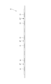
- FIG. 2A is a cross-sectional view of the lid portion 5 along the longitudinal direction of the battery tray 1 shown in FIG. 1.
- FIG. 2B is a cross-sectional view of the tray body 3 along the longitudinal direction of the battery tray 1 shown in FIG. 1.
- the tray body 3 has a bottom portion 11 , a side portion 13 and an end portion 15 .
- the tray main body 3 has a bottom surface formed by the bottom surface portion 11 , a side surface formed by the side surface portion 13 , and an end surface formed by the end surface portion 15 .
- the tray body 3 is surrounded by the bottom surface portion 11, the side surface portions 13, and the end surface portions 15, and is formed into a box shape with an open top.
- a housing space S is defined inside the box shape.
- the battery tray 1 accommodates a plurality of batteries (not shown) in the accommodation space S of the tray body 3 .
- the lid portion 5 By attaching the lid portion 5 to the upper portion of the tray body 3 , the housing space S in which the battery is housed is closed by the lid portion 5 .
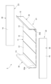
- FIG. 3 is an exploded perspective view of the tray body 3 that constitutes the battery tray 1.
- FIG. 4 is an enlarged perspective view of an end portion of the tray body 3 that constitutes the battery tray 1.
- the tray body 3 includes a concave body structural member 21 having a bottom portion 11 and a side portion 13, and a pair of end surface structural members assembled to the main body structural member 21 to form an end surface portion 15. 23.
- the end surface structural member 23 is joined to the end surface of the main body structural member 21 by MIG welding or the like from the outer peripheral side while being butted against the end surface of the main structural member 21 .
- the end surface structural member 23 is joined to the main structural member 21 by the joint 25 formed with the weld bead, and the tray main body 3 composed of the main structural member 21 and the end surface structural member 23 is completed.
- the main body structural member 21 includes a plurality of (three in this example as an example) bottom extruded panels 31 shown in FIG. 3 and a pair of side extruded panels 33 provided on both sides thereof.
- Each of the bottom extruded panel 31 and the side extruded panel 33 is formed in a plate shape.
- the plurality of bottom extruded panels 31 are arranged with their extrusion directions parallel to each other.
- both ends of the extruded bottom panel 31 in the extruding direction are referred to as end surfaces, and surfaces along the extruding direction are referred to as side surfaces (edges).
- the side extruded panels 33 are joined to the side surfaces on both sides in the direction in which the plurality of bottom extruded panels 31 are arranged.
- the side push-out panel 33 has a bent portion 33a on the side side connected to the bottom push-out panel 31, and includes a portion of the bottom portion 11 of the battery tray 1 and a side portion that is bent and erected from the bottom portion 11. 13.
- the end surface structural member 23 is joined to each end surface of the extruded bottom panel 31 and the extruded side panel 33 at both ends in the extruding direction by MIG welding or the like.
- the plurality of bottom surface extruded panels 31 and part of the side surface extruded panels 33 extending along the row direction of the bottom surface extruded panels 31 constitute the bottom portion 11 of the battery tray 1.
- the other part of the side push-out panel 33 that is, the part vertically extending from the plate surface of the bottom push-out panel 31 constitutes the side part 13 of the battery tray 1 .
- each of the pair of end surface structural members 23 is composed of one extruded end panel 35, but may be composed of a plurality of extruded end panels 35 joined together.
- the lid portion 5 assembled to the upper portion of the tray body 3 is composed of a plurality of (three as an example in this example) extruded panels 37 for the lid portion. These extruded lid panels 37 are configured by joining side surfaces along the extruding direction to each other.
- the bottom extruded panel 31, the side extruded panel 33, the end face extruded panel 35, and the lid extruded panel 37 all use a plate-like extruded material made of aluminum or an aluminum alloy.
- the extruded material is formed into a thin plate having a thickness of 8 mm, for example.
- each of the bottom extruded panel 31, the side extruded panel 33, the end surface extruded panel 35, and the lid portion extruded panel 37 has a plurality of protrusions at the center in the thickness direction.
- the hollow portion H of is molded.
- the dimension in the thickness direction of the hollow portion H is preferably about half the thickness of the extruded material.
- the aluminum alloy used for the bottom extruded panel 31, the side extruded panel 33, the end face extruded panel 35, and the lid extruded panel 37 has excellent strength and can be made thinner.
- aluminum alloys such as 5000 series, 6000 series, and 7000 series according to AA standards are preferable.
- These aluminum alloy hollow extruded profiles are appropriately combined with tempering treatments such as casting (DC casting method or continuous casting method), homogenization heat treatment, hot extrusion, solution treatment and quenching treatment, and if necessary, artificial aging treatment.
- the manufactured one can be used preferably. According to this, it is possible to make the battery tray 1 lightweight and to have a high-strength structure.
- FIG. 5A is a cross-sectional view of a joint between bottom extruded panels 31 .
- the edge of one (the right side of the paper surface) of the extruded bottom panel 31A extends along the front side surface 31a of the other (the left side of the paper surface) extrusion for the bottom surface. It has a protruding piece (first protruding piece) 41A extending toward the panel 31B.
- the edge of the other bottom surface extruded panel 31B has a protruding piece (second protruding piece) 41B extending toward the one bottom surface extruded panel 31 along the panel rear side surface 31b.
- the first protruding piece 41A of the extruded bottom panel 31A and the second protruding piece 41B of the extruded bottom panel 31B are superimposed on each other in the plate thickness direction.
- the projecting pieces 41A and 41B may be formed to extend along one of the two surfaces of the bottom extruded panels 31A and 31B.
- the side edges may be formed to extend along the other side. That is, it is sufficient that the projecting piece 41A and the projecting piece 41B can be engaged with each other to form a joint.
- a joint J1 is formed between the protruding piece 41A of one of the bottom face extruded panels 31A and the other bottom face extruded panel 31B along the panel surface 31a.
- a joint J2 is formed between the protruding piece 41B of the other extruded bottom panel 31B along the back side surface 31b of the panel and the one extruded bottom panel 31A.
- the joints J1 and J2 join the bottom extruded panels 31A and 31B to each other.
- the joints J1 and J2 are provided at different positions so as not to overlap in the plate thickness direction in the butting direction (direction along the plate surfaces) of the bottom extruded panels 31A and 31B.
- the thickness ta in the plate thickness direction of the projecting pieces 41A and 41B provided on the bottom extruded panels 31A and 31B is equal and half the thickness tb of the bottom extruded panels 31A and 31B.
- the projecting dimension W of the projecting pieces 41A and 41B in the direction of the plate surface is three times or more and four times or less the thickness tb, for example, about 25 mm.
- the depth D of the joints J1 and J2 is preferably equal to or greater than the thickness ta of the projecting pieces 41A and 41B and less than the thickness tb of the extruded bottom panel 31 . In this example, the depth D of the joint J is set to 4 mm or more and less than 8 mm.
- FIG. 5B is a cross-sectional view of the joint between the bottom extruded panel 31 and the side extruded panel 33.
- FIG. 5B As shown in FIG. 5B, at the joint between the bottom extruded panel 31 and the side extruded panel 33, the edge of the bottom extruded panel 31 extends toward the side extruded panel 33 along the front surface 31a of the panel. It has a projecting piece (first projecting piece) 41A. Similarly, the edge of the push-out panel 33 for the side surface has a projecting piece (second projecting piece) 41C extending toward the pushed-out panel 31 for the bottom surface along the back side surface 33b of the panel. These projecting pieces 41A and 41C are overlapped with each other in the plate thickness direction.
- a joint J1 is formed between the projecting piece 41A of the bottom extruded panel 31 and the side extruded panel 33 along the panel front surface 31a. Also, a joint J2 is formed between the projecting piece 41C of the push-out panel 33 for the side surface and the push-out panel 31 for the bottom surface along the back side surface 33b of the panel.
- Each of the joints J1 and J2 joins the bottom extruded panel 31 and the side extruded panel 33 .
- the joints J1 and J2 are provided at different positions so as not to overlap in the plate thickness direction in the butting direction (direction along the plate surface) of the bottom extruded panel 31 and the side extruded panel 33 .
- FIG. 5C is a cross-sectional view of a joint portion between the extruded lid panels 37 .
- the edge of one (the right side of the paper surface) of the extruded lid panel 37 extends along the front side surface 37a of the other (the left side of the paper surface).
- has a protruding piece (first protruding piece) 41D extending toward the lid push-out panel 37B.
- the edge of the other lid push-out panel 37B has a projecting piece (second projecting piece) 41E extending toward the one lid push-out panel 37A along the panel rear side surface 37b.
- These projecting pieces 41D and 41E are overlapped with each other in the plate thickness direction.
- a joint J1 is formed between the protruding piece 41D of one of the extruded lid panels 37A along the panel front surface 37a and the other extruded lid panel 37B.
- a joint J2 is formed between the projecting piece 41E of the other extruded lid panel 37B along the back side surface 37b of the panel and the extruded lid panel 37A.
- the joints J1 and J2 are provided at mutually different positions so as not to overlap in the plate thickness direction in the butting direction (direction along the plate surface) of the extruded lid panels 37A and 37B. 37B are joined together.
- the projecting pieces 41A, 41C, 41D, and 41E at the joints between the bottom extruded panel 31 and the side extruded panel 33 and the joints between the lid extruded panels 37A and 37B have the thickness ta and the projecting dimension described above.
- the dimensions of W and the depth D of the joints J1 and J2 are the same as those of the joints between the extruded bottom panels 31A and 31B described above, so description thereof will be omitted.
- the joints J1 and J2 formed at the joints between the bottom extruded panels 31, the joints between the bottom extruded panels 31 and the side extruded panels 33, and the joints between the lid extruded panels 37 are formed by friction stir welding. It is either a friction stir weld made or a fusion weld made by MIG welding. For example, all joints may be friction stir welds formed by friction stir welding, or all joints may be fusion welds formed by MIG welding. Also, only a part of the joint may be formed by friction stir welding, and the other joint may be formed by MIG welding.
- a high-strength joint can be stably obtained. Further, after processing with the friction stirring tool, the processed surface can be smoothed with high accuracy by smoothing the processed portion with a reamer or the like.
- the joining portion is formed by MIG welding, the joining can be performed at high speed, so productivity can be improved. Therefore, if the inner side of the housing space S is a joint formed by friction stir welding, and the outer side opposite to the housing space S is a joint formed by a fusion weld, the housing space S side is processed smoothly with high accuracy. As a result, the workability of arranging the battery, workability and productivity can be improved.
- FIG. 6A is a perspective view of the extruded bottom panel 31 having a cooling function
- FIG. 6B is a perspective view showing a part of the extruded bottom panel 31.
- the bottom extruded panel 31 has a hollow portion H forming a cavity in the thickness direction.
- an inlet 51 and an outlet 53 are provided at one end of the bottom extruded panel 31 .
- the hollow portion H is formed in two rows in the panel surface along the longitudinal direction of the panel, one row communicating with the inlet 51 and the other row communicating with the outlet 53 .
- the two rows of hollow portions H communicate with a communicating passage 55 formed on the other end side of the bottom extruded panel 31 to form a single U-shaped flow passage extending from the inlet 51 to the outlet 53 .
- the inlet 51 and the outlet 53 are screwed to a joint connected to a pipe serving as a coolant supply/discharge flow path.
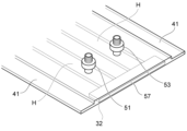
- FIG. 7A is an enlarged perspective view of one end side of the pushed bottom panel 31 of FIG. 6B
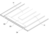
- FIG. 7B is an enlarged perspective view of the other end side of the pushed bottom panel 31 of FIG. 6B.
- the bottom extruded panel 31 is formed with recesses 32 communicating with the two rows of hollow portions H at one end in the extruding direction.
- the bottom extruded panel 31 is formed with recesses 34 communicating with the two rows of hollow portions H at the other end in the extruding direction.
- the sealing plate 59 By inserting the sealing plate 59 into the concave portion 34, the ends of the two rows of hollow portions H are closed from the outside of the panel, but a communicating passage 55 is formed between the hollow portions H, and this The communication passages 55 allow the hollow portions H to communicate with each other.
- coolant such as cooling water or air is supplied from the inlet 51 on one end side of the extruded bottom panel 31 .
- the supplied coolant flows through one row of the hollow portions H, passes through the communication passage 55 at the other end of the bottom extruded panel 31, and flows into the other row of the hollow portions H.
- the other hollow portion H As shown in FIG. Then, it flows through the other hollow portion H and is discharged from the outlet port 53 on the one end side of the bottom extruded panel 31 .
- the hollow portion H functions as a cooling channel through which the coolant flows, and the battery housed in the housing space S can be cooled.
- the configuration includes two rows of hollow portions H extending in the in-plane direction of the bottom extruded panel 31.
- a configuration including even-numbered rows of hollow portions H such as four rows and six rows may be used. good.
- the hollow portion H is divided into an outward path and a return path, and the pairs of the outward path and the return path are communicated with each other at the end opposite to the inflow port 51 and the outflow port 53 of the bottom extruded panel 31 .
- This makes it possible to easily form a plurality of reciprocating cooling passages in which the coolant supplied to one of the hollow portions H is folded back at the end where the outward path and the return path are communicated and returned from the other hollow portion H.
- FIG. 8A to 8C are cross-sectional views showing stepwise the manufacturing process of the main structural member 21. As shown in FIG.
- the edges in the row direction of the plurality of bottom extruded panels 31 are joined together.
- the bottom extruded panels 31 to be joined to each other are arranged so that the protruding pieces 41 overlap each other and are butted against each other.
- the projecting piece 41 of one of the extruded bottom panels 31 and the edge of the other extruded bottom panel 31 are joined to form the junction J1 (FIG. 5A).
- the projecting piece 41 of the other extruded bottom panel 31 and the edge of the one extruded bottom panel 31 are joined to form a joint J2 (FIG. 5A).
- FIG. 9A is an explanatory view showing how friction stir welding is performed on the butted portions of the extruded bottom panels 31, and FIG. 9B is an explanatory view illustrating how the butted portions of the extruded bottom panels 31 are MIG-welded.
- the protruding piece 41 of one of the extruded bottom panels 31 and the edge of the other extruded bottom panel 31 can be joined by friction stir welding using the friction stir tool T1.
- the projecting piece 41 of one of the extruded bottom panels 31 and the edge of the other extruded bottom panel 31 can be joined by MIG welding with the welding torch T2. Since the welding torch T2 can be set to an arbitrary torch angle, it is possible to adjust the torch angle according to the shape of the welding position, increasing the degree of freedom in construction.
- the protruding piece 41 and the edge of the extruded bottom panel 31 are joined by either friction stir welding or MIG welding on the panel front side surface 31a and the panel back side surface 31b of the bottom extruded panel 31.
- the portion to be brought into contact with the friction stir tool T1 is flat.
- the machined portion machined by the friction stirring tool T1 can be easily machined by a reamer or the like (not shown), thereby making the machined surface highly accurate and smooth.
- the joint J is formed by MIG welding, it is possible to improve productivity by joining at a high joining speed. Therefore, if the accommodation space S side is joined by friction stir welding and the outside opposite to the accommodation space S is joined by MIG welding, the productivity can be improved while the accommodation space S side is processed smoothly with high accuracy.
- the sealing gas In the case of joining by MIG welding, it is preferable to use a mixed gas in which helium is mixed with argon as the sealing gas.
- this mixed gas By using this mixed gas as the sealing gas, the strength of the arc can be increased and the welding speed can be increased. According to this, the joining speed can be increased to, for example, about 1000 mm/min to 1500 mm/min.
- the mixing ratio of helium to argon in the mixed gas is preferably 10% to 50%.
- the protruding piece 41 of the extruded bottom panel 33 and the edge of the extruded bottom panel 31, which are butted against each other on the back side of the extruded bottom panel 31 and the extruded side panel 33, are joined to form a junction J. .
- the bottom extruded panels 31 are joined by friction stir welding or MIG welding in the same manner as the above-described joining of the bottom extruded panels 31 .
- the side extruded panel 33 joined to the bottom extruded panel 31 is bent by, for example, a press machine such as a press brake.
- a press machine such as a press brake.
- a concave body structural member 21 composed of the bottom surface portion 11 and the side surface portions 13 is obtained (see FIG. 3).
- FIG. 10A and 10B are sectional views of the extruded side panel 33 for explaining the bending process of the extruded side panel 33.
- FIG. 10A if grooves 61 are formed in the bent portions, as shown in FIG.
- the structural member of the present configuration and the method for manufacturing the structural member sufficient rigidity can be ensured compared to a structural member in which plate-like layers are superimposed.
- the thickness of the joint J can be reduced, compared to a structural member in which the edges are simply butted together and joined at the same position in the surface direction, a highly accurate structure in which distortion that occurs during joining is suppressed can be achieved.
- the joining speed of the extruded panels can be improved.
- FIG. 11 and 12 are perspective views showing other body structural members.
- a side extruded panel 33 may be joined to the edges of both side surfaces (surfaces along the extruding direction) of one bottom extruded panel 31.
- two side extruded panels 33 may be joined together.
- FIG. 13 is a cross-sectional view of a joint portion explaining a step G that occurs when the bottom extruded panels 31 are butted against each other.
- a step G may occur due to misalignment at the joint portion.
- This step G is conspicuously caused by interference between the corner Cn between the edge of one of the bottom panel 31 and the projecting piece 41 and the corner Ca of the projecting piece 41 of the other projecting panel 31 .
- step G it becomes difficult to perform friction stir welding by applying the friction stir tool T1 vertically.
- friction stir welding can be performed by tilting the friction stir tool T1 obliquely with respect to the joint.
- a dedicated machine for friction stir welding must be used, which increases equipment costs and complicates setup.
- FIG. 14 is a cross-sectional view of a joint portion between the bottom extruded panels 31 having the thickened portions 71 and 73 .
- 15A to 15E are cross-sectional views showing steps of a method for manufacturing a structural member according to a modification.
- the thickness is increased along the joint formed by the end of the projecting piece 41 and the edge of the pushed-out panel 31 for the bottom surface, where the edge of the pushed-out panel 31 for the bottom surface and the projecting piece 41 meet.
- the portions 71 and 73 are formed in advance.
- the projecting dimension of these thickened portions 71 and 73 is preferably 0.5 mm, for example, and the total width dimension W of these thickened portions 71 and 73 is equal to the shoulder width Wt1 ( (See FIG. 15D).
- the corner Ca of the protruding piece 41 facing the corner Cn between the edge of the bottom panel 31 and the protruding piece 41 is circumscribed with a radius larger than the radius of the inscribed circle of the corner Cn. Mold into a shape with a circle. Then, it is possible to suppress the generation of a step G at the joint due to interference of the corner Ca of the protruding piece 41 with the corner Cn.
- the extruded bottom panels 31 to be joined are arranged so that the protruding pieces 41 overlap each other and butt against each other.
- the thickened portions 71 and 73 are cut with a cutting tool T3 such as a reamer before performing friction stir welding, as shown in FIG. 15C. Then, as shown in FIG. 15D, a smooth surface F is formed along the joint formed by the abutting portion between the edge of the extruded bottom panel 31 and the protruding piece 41 .
- the friction stir tool T1 is vertically abutted, and friction stir welding is performed along the joint by this friction stir tool T1.
- a joint J is formed at the joint where the edge of one of the extruded bottom panels 31 and the projecting piece 41 of the other extruded bottom panel 31 are butted together.
- bottom extruded panels 31 joined together are subjected to machining such as deburring and trimming using a cutting tool T3 such as a reamer. This machining is performed after at least one joint J is formed.
- friction stir welding is not difficult due to the formation of the step G due to misalignment in the joint, and the friction stir tool is applied to the joint.
- Friction stir welding can be performed smoothly by abutting T1 vertically. Therefore, friction stir welding is facilitated by attaching the friction stir tool T1 to a machine tool for machining such as a machining center without using a dedicated machine for performing friction stir welding by tilting the friction stir tool T1 with respect to the joint. can be done.
- friction stir welding can be easily performed by attaching the friction stir tool T1 to a machine tool for machining such as a machining center, so that after friction stir welding is performed by the machine tool, a cutting tool such as a reamer can be used. Machining can be easily performed by replacing T3.
- the corner Ca of the protruding piece 41 facing the corner Cn between the edge of the one bottom surface extruded panel 31 and the protruding piece 41 forms a circumscribed circle with a radius larger than the radius of the inscribed circle of the corner Cn. have. Therefore, it is possible to suppress the generation of a step G at the joint due to the corner Ca of the projecting piece 41 interfering with the corner Cn between the edge of the bottom extruded panel 31 and the projecting piece 41 . As a result, the joint can be friction stir welded more smoothly.
- One of the extruded panels has a first projecting piece extending from the edge of the extruded panel toward the other extruded panel along the panel front surface,
- the other extruded panel has a second projecting piece extending from the edge of the extruded panel toward the one extruded panel along the back side of the panel,
- a first joint is formed between the tip of the first projecting piece and the edge of the other extruded panel,
- a second joint is formed between the tip of the second projecting piece and the edge of the one extruded panel,
- the structural member, wherein the first joint portion and the second joint portion are formed at different positions in a butting direction of the extruded panels.
- the first joint formed between the projecting piece of one extruded panel and the edge of the other extruded panel, and the projecting piece of the other extruded panel and the edge of one extruded panel are provided at different positions in the butting direction of the extruded panels.
- the bonding depth can be reduced, and the bonding speed can be improved while reducing the amount of heat input.
- thermal strain can be reduced, high dimensional accuracy can be obtained.
- the depth of the first joint is greater than or equal to the thickness of the first projecting piece and less than the thickness of the extruded panel;
- the extruded panel has even-numbered rows of hollow portions extending in the in-plane direction of the extruded panel, and the even-rowed hollow portions communicate with each other at their ends.
- Structural member According to this structural member, by connecting the even-numbered hollow portions at their ends, the refrigerant sent to one of the hollow portions is folded back at the connected end portion and returned from the other hollow portion for reciprocating cooling. Flow channels can be easily formed.
- a battery tray comprising the structural member according to any one of (1) to (6). According to this battery tray, high dimensional accuracy and rigidity can be obtained, and the bonding speed can be improved, so that the configuration can improve productivity.
- a method of manufacturing a structural member that constitutes a battery tray that accommodates a plurality of batteries comprising: The edges of a plurality of extruded panels each made of an extruded material are butted against each other, and the first projecting piece extending from the edge of one extruded panel toward the other extruded panel along the panel front surface and the other extruded piece A step of forming a joint by overlapping a second projecting piece extending from the edge of the panel toward the one extruded panel along the back side of the panel in the thickness direction; forming a first joint between the tip of the first projecting piece and the edge of the other extruded panel; forming a second joint between the tip of the second projecting piece and the edge of the one extruded panel; A method of manufacturing a structural member, wherein the first joint portion and the second joint portion are formed at mutually different positions in a butting direction of the extruded panels.
- the first joint formed between the projecting piece of one extruded panel and the edge of the other extruded panel, and the projecting piece of the other extruded panel and the one extruded panel Second joints formed between the edges are provided at different positions in the butting direction of the extruded panels.
- the bonding depth can be reduced, and the bonding speed can be improved while reducing the amount of heat input.
- thermal strain can be reduced, high dimensional accuracy can be obtained.
- a thickened portion along the joint is formed in advance on the tip of the first projecting piece and the edge of the other extruded panel and the tip of the second projecting piece and the edge of the one extruded panel. keep, Before the step of forming the first joint portion and before the step of forming the second joint portion, the thickened portion is cut to form a smooth surface along the joint, and then, on the smooth surface, The method of manufacturing a structural member according to (8), wherein friction stir welding is performed along the joint to form the first joint and the second joint. According to this structural member manufacturing method, the thickened portions formed at the tip of the first projecting piece and the edge of the other extruded panel and at the tip of the second projecting piece and the edge of the one extruded panel are cut.
- a smooth surface is formed on which friction stir welding is performed along the respective joints to form a first joint and a second joint.
- friction stir welding can be performed smoothly by striking the friction stir tool vertically against the joint without making friction stir welding difficult due to the formation of a step due to misalignment in the joint. can. Therefore, friction stir welding can be easily performed by attaching the friction stir tool to a machine tool for machining such as a machining center without using a dedicated machine for performing friction stir welding by tilting the friction stir tool with respect to the joint. be able to.
- the corner of the first projecting piece facing the second corner between the edge of the one extruded panel and the second projecting piece is larger than the radius of the inscribed circle of the second corner. has a circumscribed circle of radius,
- the corner of the second projecting piece facing the first corner between the edge of the other extruded panel and the first projecting piece has a circumscribed radius larger than the radius of the inscribed circle of the first corner.
- the corner of the first projecting piece interferes with the second corner of the edge of one extruded panel and the second projecting piece, or the edge of the other extruded panel It is possible to suppress the occurrence of a step at the joint due to interference of the corner of the second projecting piece with the first corner of the first projecting piece. As a result, the joint can be friction stir welded more smoothly.
- a bottom extrusion panel disposed on the bottom of the battery tray; a side extrusion panel including a part of the bottom surface of the battery tray and a side surface bent and erected from the bottom surface; prepare a The structural member according to any one of (8) to (12), comprising forming the first joint portion and the second joint portion between the bottom extruded panel and the side extruded panel. manufacturing method. According to this method of manufacturing a structural member, it is possible to easily manufacture a structural member having high rigidity by eliminating joints between the bottom surface portion and the side surface portion while reducing the number of parts.
- a method for manufacturing a battery tray comprising manufacturing a battery tray using the structural member obtained by the method for manufacturing a structural member according to any one of (8) to (13). According to this battery tray, high dimensional accuracy and rigidity can be obtained, and the bonding speed can be improved, so that the configuration can improve productivity.
Landscapes
- Chemical & Material Sciences (AREA)
- Chemical Kinetics & Catalysis (AREA)
- General Chemical & Material Sciences (AREA)
- Electrochemistry (AREA)
- Engineering & Computer Science (AREA)
- Manufacturing & Machinery (AREA)
- Mechanical Engineering (AREA)
- Physics & Mathematics (AREA)
- Plasma & Fusion (AREA)
- Inorganic Chemistry (AREA)
- Aviation & Aerospace Engineering (AREA)
- Pressure Welding/Diffusion-Bonding (AREA)
- Secondary Cells (AREA)
- Battery Mounting, Suspending (AREA)
- Butt Welding And Welding Of Specific Article (AREA)
Abstract
構造部材は、それぞれ押出材からなる複数の押出パネルの縁部同士を突き合わせた継手が形成される。一方の押出パネルは、押出パネルの縁部から延びる第1突出片を有し、他方の押出パネルは、押出パネルの縁部から延びる第2突出片を有する。第1突出片の先端と他方の押出パネルの縁部との間に第1接合部が形成され、第2突出片の先端と一方の押出パネルの縁部との間に第2接合部が形成される。第1接合部と第2接合部とは、押出パネル同士の突き合わせ方向に互いに異なる位置に形成されている。
Description
本発明は、構造部材及び構造部材の製造方法、並びにバッテリートレイ及びバッテリートレイの製造方法に関する。
電力により走行する車両(電気自動車、ハイブリッド自動車等を含む)、及び自走式ロボット等の機器の開発が進展している。このような車両又は機器に搭載する電池システムは、一般的に、多数のバッテリー(電池、電池セル)をバッテリートレイに収容した構成を有している。
特許文献1には、複数の電池パックを収容する電池パック構造体として、一対の前フレーム及び後フレームとをそれぞれ左右のサイドフレームにて連結した外枠体と、この外枠体の底部側に配設した冷却部材とを備え、冷却部材が上部冷却層と下部冷却層とを重ね合せて内側に冷却流路を形成したものが開示されている。
また、特許文献2には、底部と、底部から立設した側壁部にて内側に電池の収納部を形成し、底部がヒートパイプ構造になっている電池収納構造体が示されている。
さらに、特許文献3には、対向配置した第1サイド部材と第2サイド部材とで、電池モジュールの収容部を形成した車両用電池ケース構造体が示されている。この電池ケース構造体では、第1サイド部材と第2サイド部材のうち、一方又は両方は、電池モジュールの側部側に位置する骨格中空部と電池モジュールの下側に位置するアンダー中空部とを有し、電池モジュールの収容部の収容底部とアンダー中空部との間にクリアランス中空部を有し、骨格中空部、クリアランス中空部及びアンダー中空部とが一体的に形成されている。
ところで、特許文献1に記載の構造体は、その底部となる冷却部材を、それぞれ薄い板状の上部冷却層と下部冷却層とを重ね合せて形成しているため、剛性を十分に確保することが困難である。
また、特許文献2,3に記載の構造体は、複数の押出材の端面を突き合わせて接合させて底部を構成する際に、その接合箇所に熱と応力が集中して歪みが生じ易く、高精度に作製することが困難である。
そこで本発明は、十分な剛性を確保しつつ高精度にバッテリートレイの作製が可能な構造部材及び構造部材の製造方法、並びにバッテリートレイ及びバッテリートレイの製造方法を提供することを目的とする。
本発明は下記の構成からなる。
(1) 複数のバッテリーが収容されるバッテリートレイを構成する構造部材であって、
それぞれ押出材からなる複数の押出パネルの縁部同士を突き合わせた継手が形成され、
一方の前記押出パネルは、当該押出パネルの縁部からパネル表側面に沿って他方の前記押出パネルに向かって延びる第1突出片を有し、
他方の前記押出パネルは、当該押出パネルの縁部から、パネル裏側面に沿って前記一方の押出パネルに向かって延びる第2突出片を有し、
前記第1突出片の先端と前記他方の押出パネルの前記縁部との間に第1接合部が形成され、前記第2突出片の先端と前記一方の押出パネルの前記縁部との間に第2接合部が形成され、
前記第1接合部と前記第2接合部とは、前記押出パネル同士の突き合わせ方向に互いに異なる位置に形成されている、構造部材。
(2) (1)に記載の構造部材を含んで構成される、バッテリートレイ。
(3) 複数のバッテリーが収容されるバッテリートレイを構成する構造部材の製造方法であって、
それぞれ押出材からなる複数の押出パネルの縁部同士を突き合わせ、一方の前記押出パネルの縁部からパネル表側面に沿って他方の前記押出パネルに向かって延びる第1突出片と、他方の前記押出パネルの縁部からパネル裏側面に沿って前記一方の押出パネルに向かって延びる第2突出片とを板厚方向に重ねて継手を形成する工程と、
前記第1突出片の先端と前記他方の押出パネルの前記縁部との間に第1接合部を形成する工程と、
前記第2突出片の先端と前記一方の押出パネルの前記縁部との間に第2接合部を形成する工程と、を有し、
前記第1接合部と前記第2接合部とを、前記押出パネル同士の突き合わせ方向に互いに異なる位置に形成する、構造部材の製造方法。
(4) (3)に記載の構造部材の製造方法により得られた前記構造部材を用いてバッテリートレイを製造する、バッテリートレイの製造方法。
(1) 複数のバッテリーが収容されるバッテリートレイを構成する構造部材であって、
それぞれ押出材からなる複数の押出パネルの縁部同士を突き合わせた継手が形成され、
一方の前記押出パネルは、当該押出パネルの縁部からパネル表側面に沿って他方の前記押出パネルに向かって延びる第1突出片を有し、
他方の前記押出パネルは、当該押出パネルの縁部から、パネル裏側面に沿って前記一方の押出パネルに向かって延びる第2突出片を有し、
前記第1突出片の先端と前記他方の押出パネルの前記縁部との間に第1接合部が形成され、前記第2突出片の先端と前記一方の押出パネルの前記縁部との間に第2接合部が形成され、
前記第1接合部と前記第2接合部とは、前記押出パネル同士の突き合わせ方向に互いに異なる位置に形成されている、構造部材。
(2) (1)に記載の構造部材を含んで構成される、バッテリートレイ。
(3) 複数のバッテリーが収容されるバッテリートレイを構成する構造部材の製造方法であって、
それぞれ押出材からなる複数の押出パネルの縁部同士を突き合わせ、一方の前記押出パネルの縁部からパネル表側面に沿って他方の前記押出パネルに向かって延びる第1突出片と、他方の前記押出パネルの縁部からパネル裏側面に沿って前記一方の押出パネルに向かって延びる第2突出片とを板厚方向に重ねて継手を形成する工程と、
前記第1突出片の先端と前記他方の押出パネルの前記縁部との間に第1接合部を形成する工程と、
前記第2突出片の先端と前記一方の押出パネルの前記縁部との間に第2接合部を形成する工程と、を有し、
前記第1接合部と前記第2接合部とを、前記押出パネル同士の突き合わせ方向に互いに異なる位置に形成する、構造部材の製造方法。
(4) (3)に記載の構造部材の製造方法により得られた前記構造部材を用いてバッテリートレイを製造する、バッテリートレイの製造方法。
本発明によれば、十分な剛性を確保しつつ高精度にバッテリートレイの作製が可能となる。
以下、本発明の実施形態について、図面を参照して詳細に説明する。
本発明に係る構造部材は、例えば、車載用のバッテリートレイを構成する部材として説明するが、これに限らず、例えば自走式ロボット等の他の機器に搭載するバッテリートレイを構成するものであってもよい。
本発明に係る構造部材は、例えば、車載用のバッテリートレイを構成する部材として説明するが、これに限らず、例えば自走式ロボット等の他の機器に搭載するバッテリートレイを構成するものであってもよい。
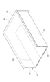
図1は、バッテリートレイ1の分解斜視図である。
図1に示す本実施形態の構造部材は、車載用のバッテリートレイ1を構成する。バッテリートレイ1は、複数のバッテリーを収容可能であって、電力により走行する車両(電気自動車、ハイブリッド自動車等を含む)の車体フロアの下側に配置された形態で車体に固定される。
図1に示す本実施形態の構造部材は、車載用のバッテリートレイ1を構成する。バッテリートレイ1は、複数のバッテリーを収容可能であって、電力により走行する車両(電気自動車、ハイブリッド自動車等を含む)の車体フロアの下側に配置された形態で車体に固定される。
バッテリートレイ1は、平面視で長方形状のトレイ本体3と、このトレイ本体3の上部に組み付けられる蓋部5とを備える。
図2Aは、図1に示すバッテリートレイ1の長手方向に沿った蓋部5の断面図である。図2Bは、図1に示すバッテリートレイ1の長手方向に沿ったトレイ本体3の断面図である。
トレイ本体3は、底面部11と、側面部13と、端面部15とを有する。トレイ本体3は、底面部11によって底面が構成され、側面部13によって側面が構成され、端面部15によって端面が構成されている。これにより、トレイ本体3は、底面部11、側面部13及び端面部15によって囲われ、上方が開放された箱形に形成される。箱形の内部には、収容空間Sが画成される。
トレイ本体3は、底面部11と、側面部13と、端面部15とを有する。トレイ本体3は、底面部11によって底面が構成され、側面部13によって側面が構成され、端面部15によって端面が構成されている。これにより、トレイ本体3は、底面部11、側面部13及び端面部15によって囲われ、上方が開放された箱形に形成される。箱形の内部には、収容空間Sが画成される。
バッテリートレイ1は、トレイ本体3の収容空間Sに複数のバッテリー(図示略)が収容される。そして、トレイ本体3の上部に蓋部5を組み付けることにより、バッテリーが収容された収容空間Sが蓋部5によって塞がれる。
図3は、バッテリートレイ1を構成するトレイ本体3の分解斜視図である。図4は、バッテリートレイ1を構成するトレイ本体3の端部の拡大斜視図である。
図3に示すように、トレイ本体3は、底面部11と側面部13とからなる凹状の本体構造部材21と、この本体構造部材21に組み付けられて端面部15を構成する一対の端面構造部材23とから構成される。
図4に示すように、端面構造部材23は、本体構造部材21の端面に突き合わされた状態で、外周側からMIG溶接等により接合される。これにより、端面構造部材23は、溶接ビードが形成された接合部25によって本体構造部材21に接合され、本体構造部材21と端面構造部材23とからなるトレイ本体3ができあがる。
本体構造部材21は、図3に示す複数(本例では一例として3つ)の底面用押出パネル31と、その両脇側に設けられた一対の側面用押出パネル33とを備える。底面用押出パネル31及び側面用押出パネル33は、それぞれが板状に形成されている。複数の底面用押出パネル31は、押出方向を互いに平行にして配置される。ここでは、底面用押出パネル31の押出方向の両端を端面といい、押出方向に沿った面を側面(縁部)という。
複数の底面用押出パネル31の並び方向の両脇の側面に、側面用押出パネル33が接合される。側面用押出パネル33は、底面用押出パネル31と接続される側面側に屈曲部33aを有し、バッテリートレイ1の底面部11の一部及び底面部11から屈曲して立設された側面部13を含んで構成されている。端面構造部材23は、底面用押出パネル31と側面用押出パネル33の押出方向両端の各端面にMIG溶接等により接合される。
そして、本体構造部材21は、複数の底面用押出パネル31と、底面用押出パネル31の並び方向に沿って延びる側面用押出パネル33の一部とが、バッテリートレイ1の底面部11を構成する。また、側面用押出パネル33の他の部分、即ち、底面用押出パネル31の板面から垂直方向に延びて立設された部分がバッテリートレイ1の側面部13を構成する。さらに、一対の端面構造部材23は、それぞれ1枚の端面用押出パネル35から構成されているが、複数の端面用押出パネル35を接合して構成したものでもよい。
トレイ本体3の上部に組み付けられる蓋部5は、図1に示すように、複数(本例では一例として3つ)の蓋部用押出パネル37から構成される。これら蓋部用押出パネル37は、押出方向に沿った側面同士を互いに接合して構成されている。
底面用押出パネル31,側面用押出パネル33、端面用押出パネル35及び蓋部用押出パネル37は、いずれもアルミニウムまたはアルミニウム合金を素材とした板状の押出材が用いられる。押出材は、例えば厚さが8mmの薄板状に成形される。図2A,図2B、図4に示すように、底面用押出パネル31、側面用押出パネル33、端面用押出パネル35及び蓋部用押出パネル37には、その厚さ方向の中央に、それぞれ複数の中空部Hが成形されている。中空部Hの厚さ方向の寸法は、押出材の厚さの半分程度が好ましい。
底面用押出パネル31,側面用押出パネル33、端面用押出パネル35及び蓋部用押出パネル37として使用されるアルミニウム合金は、優れた強度を有し、より薄肉化が可能である点で、JIS又はAA規格でいう5000系、6000系、7000系などのアルミ合金が好ましい。これらアルミニウム合金の中空押出形材は、鋳造(DC鋳造法又は連続鋳造法)、均質化熱処理、熱間押出、溶体化および焼入れ処理、必要により人工時効処理、などの調質処理を適宜組み合わせて製造したものを好適に使用できる。これによれば、バッテリートレイ1を軽量化しつつ高強度な構成にできる。
次に、底面用押出パネル31同士の接合箇所、底面用押出パネル31と側面用押出パネル33との接合箇所及び蓋部用押出パネル37同士の接合箇所の構造について詳細に説明する。
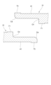
図5Aは、底面用押出パネル31同士の接合箇所の断面図である。
図5Aに示すように、底面用押出パネル31同士の接合箇所において、一方(紙面右側)の底面用押出パネル31Aの縁部は、パネル表側面31aに沿って他方(紙面左側)の底面用押出パネル31Bへ向かって延びる突出片(第1突出片)41Aを有している。同様に、他方の底面用押出パネル31Bの縁部は、パネル裏側面31bに沿って一方の底面用押出パネル31へ向かって延びる突出片(第2突出片)41Bを有している。これらの底面用押出パネル31Aの第1突出片41Aと、底面用押出パネル31Bの第2突出片41Bは、板厚方向に互いに重ね合わされている。
図5Aに示すように、底面用押出パネル31同士の接合箇所において、一方(紙面右側)の底面用押出パネル31Aの縁部は、パネル表側面31aに沿って他方(紙面左側)の底面用押出パネル31Bへ向かって延びる突出片(第1突出片)41Aを有している。同様に、他方の底面用押出パネル31Bの縁部は、パネル裏側面31bに沿って一方の底面用押出パネル31へ向かって延びる突出片(第2突出片)41Bを有している。これらの底面用押出パネル31Aの第1突出片41Aと、底面用押出パネル31Bの第2突出片41Bは、板厚方向に互いに重ね合わされている。
個々の底面用押出パネル31A,31Bは、それぞれ同一の形状であると汎用性、施工性を高められる。なお、突出片41A,41Bは、底面用押出パネル31A,31Bの両面のうち、一方の面に沿って延びて形成されてもよく、片側の縁部では一方の面に沿って延び、その反対側の縁部では他方の面に沿って延びて形成されていてもよい。つまり、突出片41Aと突出片41Bとが、互いに係合して継手を形成できればよい。
パネル表側面31aに沿った一方の底面用押出パネル31Aの突出片41Aと他方の底面用押出パネル31Bとの間には接合部J1が形成されている。また、パネル裏側面31bに沿った他方の底面用押出パネル31Bの突出片41Bと一方の底面用押出パネル31Aとの間には接合部J2が形成されている。各接合部J1,J2は、底面用押出パネル31A,31B同士を接合する。接合部J1,J2は、底面用押出パネル31A,31B同士の突き合わせ方向(板面に沿った方向)において、板厚方向に重ならない互いに異なる位置に設けられている。
底面用押出パネル31A,31Bに設けられた突出片41A,突出片41Bの板厚方向の厚さtaはそれぞれ等しく、底面用押出パネル31A,31Bの厚さtbの半分となっている。また、突出片41A,突出片41Bの板面方向への突出寸法Wは、厚さtbの3倍以上、4倍以下、例えば25mm程度とされている。接合部J1,J2の深さDは、突出片41A,41Bの厚さta以上、底面用押出パネル31の厚さtb未満が好ましい。本例では、接合部Jの深さDは、4mm以上、8mm未満にしている。
図5Bは、底面用押出パネル31と側面用押出パネル33との接合箇所の断面図である。
図5Bに示すように、底面用押出パネル31と側面用押出パネル33との接合箇所において、底面用押出パネル31の縁部は、パネル表側面31aに沿って側面用押出パネル33へ向かって延びる突出片(第1突出片)41Aを有している。同様に、側面用押出パネル33の縁部は、パネル裏側面33bに沿って底面用押出パネル31へ向かって延びる突出片(第2突出片)41Cを有している。これら突出片41A,41Cは、板厚方向に互いに重ね合わされている。
図5Bに示すように、底面用押出パネル31と側面用押出パネル33との接合箇所において、底面用押出パネル31の縁部は、パネル表側面31aに沿って側面用押出パネル33へ向かって延びる突出片(第1突出片)41Aを有している。同様に、側面用押出パネル33の縁部は、パネル裏側面33bに沿って底面用押出パネル31へ向かって延びる突出片(第2突出片)41Cを有している。これら突出片41A,41Cは、板厚方向に互いに重ね合わされている。
そして、パネル表側面31aに沿った底面用押出パネル31の突出片41Aと側面用押出パネル33との間には接合部J1が形成されている。また、パネル裏側面33bに沿った側面用押出パネル33の突出片41Cと底面用押出パネル31との間には接合部J2が形成されている。各接合部J1,J2は、底面用押出パネル31と側面用押出パネル33とを接合する。接合部J1,J2は、底面用押出パネル31と側面用押出パネル33との突き合わせ方向(板面に沿った方向)において、板厚方向に重ならない互いに異なる位置に設けられている。
図5Cは、蓋部用押出パネル37同士の接合箇所の断面図である。
図5Cに示すように、蓋部用押出パネル37A,37B同士の接合箇所において、一方(紙面右側)の蓋部用押出パネル37の縁部は、パネル表側面37aに沿って他方(紙面左側)の蓋部用押出パネル37Bへ向かって延びる突出片(第1突出片)41Dを有している。同様に、他方の蓋部用押出パネル37Bの縁部は、パネル裏側面37bに沿って一方の蓋部用押出パネル37Aへ向かって延びる突出片(第2突出片)41Eを有している。これら突出片41D,41Eは、板厚方向に互いに重ね合わされている。
図5Cに示すように、蓋部用押出パネル37A,37B同士の接合箇所において、一方(紙面右側)の蓋部用押出パネル37の縁部は、パネル表側面37aに沿って他方(紙面左側)の蓋部用押出パネル37Bへ向かって延びる突出片(第1突出片)41Dを有している。同様に、他方の蓋部用押出パネル37Bの縁部は、パネル裏側面37bに沿って一方の蓋部用押出パネル37Aへ向かって延びる突出片(第2突出片)41Eを有している。これら突出片41D,41Eは、板厚方向に互いに重ね合わされている。
そして、パネル表側面37aに沿った一方の蓋部用押出パネル37Aの突出片41Dと他方の蓋部用押出パネル37Bとの間には接合部J1が形成されている。また、パネル裏側面37bに沿った他方の蓋部用押出パネル37Bの突出片41Eと一方の蓋部用押出パネル37Aとの間には接合部J2が形成されている。各接合部J1,J2は、蓋部用押出パネル37A,37B同士の突き合わせ方向(板面に沿った方向)において、板厚方向に重ならない互いに異なる位置に設けられ、蓋部用押出パネル37A,37B同士を接合する。
なお、底面用押出パネル31と側面用押出パネル33との接合箇所及び蓋部用押出パネル37A,37B同士の接合箇所における突出片41A,41C,41D,41Eは、前述した厚さta、突出寸法W、接合部J1,J2の深さDの各寸法が前述した底面用押出パネル31A,31B同士の接合箇所と同様であるので、その説明を省略する。
底面用押出パネル31同士の接合箇所、底面用押出パネル31と側面用押出パネル33との接合箇所及び蓋部用押出パネル37同士の接合箇所に形成する接合部J1,J2は、摩擦撹拌溶接によって形成された摩擦撹拌溶接部、又はMIG溶接によって形成された溶融溶接部のいずれかである。例えば、接合部の全てが摩擦撹拌溶接によって形成された摩擦撹拌溶接部であってもよく、接合部の全てがMIG溶接によって形成された溶融溶接部であってもよい。また、接合部の一部のみが摩擦撹拌溶接によって形成され、他の接合部がMIG溶接によって形成されていてもよい。
特に摩擦撹拌溶接によって接合部を形成する場合、高強度な接合形態が安定して得られる。また、摩擦撹拌ツールによって加工した後、加工箇所をリーマ等によって平滑に加工することで、加工面を高精度な平滑面にできる。一方、MIG溶接によって接合部を形成する場合、高速に接合できるため生産性を向上できる。したがって、収容空間Sとなる内側を摩擦撹拌溶接部からなる接合部とし、収容空間Sと反対側の外側を溶融溶接部からなる接合部とすれば、収容空間S側を高精度に平滑に加工して、バッテリーの配置作業性、施工性及び生産性を高められる。
次に、底面用押出パネル31に冷却機能を持たせた構成例について説明する。
図6Aは、冷却機能を有する底面用押出パネル31の斜視図、図6Bは、底面用押出パネル31の一部を透視して示した斜視図である。
図6Aは、冷却機能を有する底面用押出パネル31の斜視図、図6Bは、底面用押出パネル31の一部を透視して示した斜視図である。
図6A及び図6Bに示すように、底面用押出パネル31は、厚さ方向に空洞を形成する中空部Hを有する。また、底面用押出パネル31の一端側に、流入口51と流出口53が設けられている。中空部Hは、パネル長手方向に沿ってパネル面内で2列に形成され、一方の列に流入口51が連通され、他方の列に流出口53が連通されている。2列の中空部Hは、底面用押出パネル31の他端側に形成された連通路55に連通し、流入口51から流出口53まで連続する一本のU字形の流路を形成する。流入口51と流出口53には、図示はしないが、冷媒の給排出流路となるパイプに接続されたジョイントがねじ締結される。
図7Aは、図6Bの底面用押出パネル31の一端側の拡大斜視図、図7Bは、図6Bの底面用押出パネル31の他端側の拡大斜視図である。
図7Aに示すように、底面用押出パネル31は、その押出方向の一端部に、2列の中空部Hにそれぞれ連通する凹部32が形成される。この凹部32に封止板57が挿入されることで、2列の中空部Hの端部が閉塞される。
図7Aに示すように、底面用押出パネル31は、その押出方向の一端部に、2列の中空部Hにそれぞれ連通する凹部32が形成される。この凹部32に封止板57が挿入されることで、2列の中空部Hの端部が閉塞される。
また、図7Bに示すように、底面用押出パネル31は、押出方向の他端部に、2列の中空部Hにそれぞれ連通する凹部34が形成される。この凹部34に封止板59が挿入されることで、2列の中空部Hの端部がパネル外側に対して閉塞されるが、中空部H同士の間に連通路55が形成され、この連通路55によって中空部H同士が連通される。
上記構成の底面用押出パネル31では、底面用押出パネル31の一端側の流入口51から、例えば、冷却水、空気等の冷媒が供給される。すると、供給された冷媒は、一方の列の中空部Hを流れ、底面用押出パネル31の他端の連通路55を通り、他方の列の中空部Hに流れる。そして、他方の中空部Hを流れ、底面用押出パネル31の一端側の流出口53から排出される。これにより、底面用押出パネル31では、中空部Hが冷媒を流動させる冷却流路として機能して、収容空間Sに収容されたバッテリーを冷却できる。
上記例では、底面用押出パネル31の面内方向に延びる2列の中空部Hを備えた構成であるが、4列、6列等の偶数列の中空部Hを備えた構成であってもよい。その場合、中空部Hを往路と復路とに分けて、底面用押出パネル31の流入口51,流出口53とは反対側の端部で往路と復路との組同士を連通させる。これにより、一方の中空部Hへ供給した冷媒を、往路と復路とを連通させた端部で折り返させて、他方の中空部Hから戻す複数の往復冷却流路を容易に形成できる。
次に、構造部材の製造方法について、本体構造部材21を製造する場合を例に説明する。
図8A~図8Cは、本体構造部材21の製造工程を段階的に示す断面図である。
図8A~図8Cは、本体構造部材21の製造工程を段階的に示す断面図である。
図8Aに示すように、まず、複数の底面用押出パネル31の並び方向の縁部同士を接合する。具体的には、互いに接合させる底面用押出パネル31を、突出片41が互いに重なるように配置させて突き合わせる。そして、前述したように、一方の底面用押出パネル31の突出片41と他方の底面用押出パネル31の縁部とを接合して接合部J1(図5A)を形成する。その後、他方の底面用押出パネル31の突出片41と一方の底面用押出パネル31の縁部を接合させて接合部J2(図5A)を形成する。
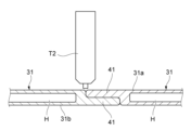
図9Aは、底面用押出パネル31同士の突き合わせ箇所を摩擦撹拌溶接する様子を示す説明図、図9Bは、底面用押出パネル31同士の突き合わせ箇所をMIG溶接する様子を示す説明図である。
図9Aに示すように、摩擦撹拌ツールT1によって、一方の底面用押出パネル31の突出片41と他方の底面用押出パネル31の縁部を摩擦撹拌溶接により接合できる。また、図9Bに示すように、溶接トーチT2によって、一方の底面用押出パネル31の突出片41と他方の底面用押出パネル31の縁部をMIG溶接により接合できる。溶接トーチT2は任意のトーチ角に設定できるため、接合位置の形状に応じてトーチ角の調整が可能となり、施工自由度を高められる。
図9Aに示すように、摩擦撹拌ツールT1によって、一方の底面用押出パネル31の突出片41と他方の底面用押出パネル31の縁部を摩擦撹拌溶接により接合できる。また、図9Bに示すように、溶接トーチT2によって、一方の底面用押出パネル31の突出片41と他方の底面用押出パネル31の縁部をMIG溶接により接合できる。溶接トーチT2は任意のトーチ角に設定できるため、接合位置の形状に応じてトーチ角の調整が可能となり、施工自由度を高められる。
このように、底面用押出パネル31のパネル表側面31a及びパネル裏側面31bにおいて、突出片41と底面用押出パネル31の縁部とを、摩擦撹拌溶接及びMIG溶接のいずれかで接合させる。
擦撹拌溶接によって接合部Jを形成する場合、摩擦撹拌ツールT1を接触させる箇所が平坦であるのが好ましい。その場合、摩擦撹拌ツールT1によって加工した加工箇所を、不図示のリーマ等によって平易に加工でき、これにより、加工面を高精度な平滑面にできる。また、MIG溶接によって接合部Jを形成する場合、高い接合速度で接合して生産性を向上できる。したがって、収容空間S側を摩擦撹拌溶接によって接合し、収容空間Sと反対側の外側をMIG溶接によって接合すれば、収容空間S側を高精度に平滑に加工しつつ生産性を高められる。
なお、MIG溶接による接合の場合、シールガスとして、アルゴンにヘリウムを混合させた混合ガスを用いるのが好ましい。この混合ガスをシールガスとして用いることにより、アークの強度を高めて接合速度をより高速化できる。これによれば、接合速度を、例えば1000mm/min~1500mm/min程度まで高速化が可能となる。なお、混合ガスにおけるアルゴンに対するヘリウムの混合率は10%~50%とするのが好ましい。
次に、図8Bに示すように、複数の底面用押出パネル31を接合した後、底面用押出パネル31の並び方向の両縁部に側面用押出パネル33を接合させる。具体的には、底面用押出パネル31及び側面用押出パネル33の突出片41が互いに重なるように突き合わせる。そして、底面用押出パネル31及び側面用押出パネル33のパネル表側面で突き合わされている底面用押出パネル31の突出片41と側面用押出パネル33の縁部とを接合して接合部Jを形成する。その後、底面用押出パネル31及び側面用押出パネル33の裏面側で突き合わされている側面用押出パネル33の突出片41と底面用押出パネル31の縁部とを接合して接合部Jを形成する。この場合も前述した底面用押出パネル31同士の接合と同様に、摩擦撹拌溶接又はMIG溶接により接合する。
次に、図8Cに示すように、底面用押出パネル31に接合した側面用押出パネル33を、例えば、プレスブレーキ等のプレス加工機によって屈曲させる。これにより、底面部11と側面部13とからなる凹状の本体構造部材21が得られる(図3参照)。
このとき、側面用押出パネル33の屈曲箇所における屈曲方向の内側に溝部61を形成しておくのが好ましい。
図10A及び図10Bは、側面用押出パネル33の屈曲工程を説明する側面用押出パネル33の断面図である。図10Aに示すように、屈曲させる箇所に溝部61を形成しておけば、図10Bに示すように、この溝部61で側面用押出パネル33を無理なく容易に屈曲させることが可能となる。
図10A及び図10Bは、側面用押出パネル33の屈曲工程を説明する側面用押出パネル33の断面図である。図10Aに示すように、屈曲させる箇所に溝部61を形成しておけば、図10Bに示すように、この溝部61で側面用押出パネル33を無理なく容易に屈曲させることが可能となる。
以上、説明したように、本構成の構成部材及び構成部材の製造方法によれば、板状の層を重ね合わせた構造部材と比較して剛性を十分に確保できる。また、接合部Jの厚さを薄くできるので、単に縁部同士を突き合わせて面方向の同一位置で接合させた構造部材と比較し、接合時に生じる歪みが抑えられた高精度な構成にでき、しかも、押出パネル同士の接合速度を向上できる。そして、この構造部材を用いることにより、高強度で高精度なバッテリートレイ1を容易に作製できる。
図11,図12は、他の本体構造部材を示す斜視図である。
本体構造部材21としては、図11に示すように、1つの底面用押出パネル31の両側面(押出方向に沿った面)の縁部に側面用押出パネル33を接合したものでもよく、また、図12に示すように、2つの側面用押出パネル33同士を接合したものでもよい。
本体構造部材21としては、図11に示すように、1つの底面用押出パネル31の両側面(押出方向に沿った面)の縁部に側面用押出パネル33を接合したものでもよく、また、図12に示すように、2つの側面用押出パネル33同士を接合したものでもよい。
(変形例)
次に、変形例について説明する。
図13は、底面用押出パネル31同士を突き合せた際に生じる段差Gを説明する継手部分の断面図である。
図13に示すように、例えば、互いに接合させる底面用押出パネル31を、突出片41が互いに重なるように配置させて突き合わせた際に、継手部分に目違いによる段差Gが生じることがある。この段差Gは、一方の底面用押出パネル31の縁部と突出片41との隅部Cnに対して他方の押出パネル31の突出片41の角部Caが干渉することにより顕著に生じる。
次に、変形例について説明する。
図13は、底面用押出パネル31同士を突き合せた際に生じる段差Gを説明する継手部分の断面図である。
図13に示すように、例えば、互いに接合させる底面用押出パネル31を、突出片41が互いに重なるように配置させて突き合わせた際に、継手部分に目違いによる段差Gが生じることがある。この段差Gは、一方の底面用押出パネル31の縁部と突出片41との隅部Cnに対して他方の押出パネル31の突出片41の角部Caが干渉することにより顕著に生じる。
このような段差Gが生じていると、摩擦撹拌ツールT1を垂直に当てて摩擦撹拌溶接することが困難となる。この場合、継手に対して摩擦撹拌ツールT1を斜めに傾けることにより摩擦撹拌溶接を行うことが可能である。しかし、この場合、摩擦撹拌溶接を行う専用機を用いなければならず、設備費が嵩張り、段取りも煩雑となる。
次に、押出パネル同士の接合の仕方の変形例について、底面用押出パネル31同士を接合させる場合を例示して説明する。
なお、上記実施形態と同一構造部分は、同一符号を付して説明を省略する。
図14は、増厚部71,73を有する底面用押出パネル31同士の継手部分の断面図である。図15A~図15Eは、変形例に係る構造部材の製造方法の工程を段階的に示す断面図である。
なお、上記実施形態と同一構造部分は、同一符号を付して説明を省略する。
図14は、増厚部71,73を有する底面用押出パネル31同士の継手部分の断面図である。図15A~図15Eは、変形例に係る構造部材の製造方法の工程を段階的に示す断面図である。
図14に示すように、変形例では、突出片41の先端と底面用押出パネル31の縁部に、底面用押出パネル31の縁部と突出片41との突き合わせ箇所からなる継手に沿う増厚部71,73を予め形成しておく。これらの増厚部71,73の突出寸法は、例えば、0.5mmとするのが好ましく、また、これらの増厚部71,73の合計幅寸法Wは、摩擦撹拌ツールT1のショルダ幅Wt1(図15D参照)以上とするのが好ましい。
さらに、変形例では、底面用押出パネル31の縁部と突出片41との隅部Cnに対向する突出片41の角部Caを、隅部Cnの内接円の半径よりも大きい半径の外接円を有する形状に成形する。すると、隅部Cnに対して突出片41の角部Caが干渉することによる継手での段差Gの発生を抑えることができる。
図15A及び図15Bに示すように、底面用押出パネル31同士を接合させるには、互いに接合させる底面用押出パネル31を、突出片41が互いに重なるように配置させて突き合わせる。
このように、底面用押出パネル31同士を突き合せたら、図15Cに示すように、摩擦撹拌溶接を行う前に、リーマ等の切削工具T3によって増厚部71,73を切削する。すると、図15Dに示すように、底面用押出パネル31の縁部と突出片41との突き合わせ箇所からなる継手に沿う平滑面Fが形成される。
次に、平滑面Fにおいて、摩擦撹拌ツールT1を垂直に突き当て、この摩擦撹拌ツールT1によって、継手に沿って摩擦撹拌溶接する。これにより、図15Eに示すように、一方の底面用押出パネル31の縁部と他方の底面用押出パネル31の突出片41とを突き合せた継手部分に接合部Jを形成する。
その後、裏面側においても、同様に、増厚部71,73を切削して継手に沿う平滑面Fを形成し、この平滑面Fに摩擦撹拌ツールT1を垂直に突き当て、この摩擦撹拌ツールT1によって、継手に沿って摩擦撹拌溶接する。これにより、他方の底面用押出パネル31の縁部と一方の底面用押出パネル31の突出片41とを突き合せた継手部分に接合部Jを形成する。
なお、互いに接合させた底面用押出パネル31に対して、例えば、リーマ等の切削工具T3によるバリ取りやトリミングなどの機械加工を施す。この機械加工は、少なくとも一方の接合部Jの形成後に行う。
このように、変形例に係る構造部材の製造方法によれば、継手に目違いによる段差Gが形成されていることによって摩擦撹拌溶接が困難となるようなことなく、継手に対して摩擦撹拌ツールT1を垂直に突き当てて円滑に摩擦撹拌溶接を行うことができる。したがって、継手に対して摩擦撹拌ツールT1を斜めに傾けて摩擦撹拌溶接を行う専用機を用いることなく、マシニングセンタ等の機械加工用の工作機械に摩擦撹拌ツールT1を装着させて摩擦撹拌溶接を容易に行うことができる。
このように、マシニングセンタ等の機械加工用の工作機械に摩擦撹拌ツールT1を装着させて摩擦撹拌溶接を容易に行うことができるので、工作機械によって摩擦撹拌溶接を行った後に、リーマ等の切削工具T3を付け替えて機械加工を容易に行うことができる。
また、一方の底面用押出パネル31の縁部と突出片41との隅部Cnに対向する突出片41の角部Caが、隅部Cnの内接円の半径よりも大きい半径の外接円を有している。したがって、底面用押出パネル31の縁部と突出片41との隅部Cnに対して突出片41の角部Caが干渉することによる継手での段差Gの発生を抑えることができる。これにより、継手に対する摩擦撹拌溶接をより円滑に行うことができる。
このように、本発明は上記の実施形態に限定されるものではなく、実施形態の各構成を相互に組み合わせること、及び明細書の記載、並びに周知の技術に基づいて、当業者が変更、応用することも本発明の予定するところであり、保護を求める範囲に含まれる。
以上の通り、本明細書には次の事項が開示されている。
(1) 複数のバッテリーが収容されるバッテリートレイを構成する構造部材であって、
それぞれ押出材からなる複数の押出パネルの縁部同士を突き合わせた継手が形成され、
一方の前記押出パネルは、当該押出パネルの縁部からパネル表側面に沿って他方の前記押出パネルに向かって延びる第1突出片を有し、
他方の前記押出パネルは、当該押出パネルの縁部から、パネル裏側面に沿って前記一方の押出パネルに向かって延びる第2突出片を有し、
前記第1突出片の先端と前記他方の押出パネルの前記縁部との間に第1接合部が形成され、
前記第2突出片の先端と前記一方の押出パネルの前記縁部との間に第2接合部が形成され、
前記第1接合部と前記第2接合部とは、前記押出パネル同士の突き合わせ方向に互いに異なる位置に形成されている、構造部材。
この構造部材によれば、一方の押出パネルの突出片と他方の押出パネルの縁部との間に形成した第1接合部、及び他方の押出パネルの突出片と一方の押出パネルの縁部との間に形成した第2接合部が、それぞれ押出パネル同士の突き合わせ方向における異なる位置に設けられる。これにより、接合深さを小さくでき、入熱量を低減しつつ、接合速度を向上できる。また、熱歪みを低減できるため、高い寸法精度が得られる。
(1) 複数のバッテリーが収容されるバッテリートレイを構成する構造部材であって、
それぞれ押出材からなる複数の押出パネルの縁部同士を突き合わせた継手が形成され、
一方の前記押出パネルは、当該押出パネルの縁部からパネル表側面に沿って他方の前記押出パネルに向かって延びる第1突出片を有し、
他方の前記押出パネルは、当該押出パネルの縁部から、パネル裏側面に沿って前記一方の押出パネルに向かって延びる第2突出片を有し、
前記第1突出片の先端と前記他方の押出パネルの前記縁部との間に第1接合部が形成され、
前記第2突出片の先端と前記一方の押出パネルの前記縁部との間に第2接合部が形成され、
前記第1接合部と前記第2接合部とは、前記押出パネル同士の突き合わせ方向に互いに異なる位置に形成されている、構造部材。
この構造部材によれば、一方の押出パネルの突出片と他方の押出パネルの縁部との間に形成した第1接合部、及び他方の押出パネルの突出片と一方の押出パネルの縁部との間に形成した第2接合部が、それぞれ押出パネル同士の突き合わせ方向における異なる位置に設けられる。これにより、接合深さを小さくでき、入熱量を低減しつつ、接合速度を向上できる。また、熱歪みを低減できるため、高い寸法精度が得られる。
(2) 前記第1接合部の深さは、前記第1突出片の厚さ以上、前記押出パネルの厚さ未満であり、
前記第2接合部の深さは、前記第2突出片の厚さ以上、前記押出パネルの厚さ未満である、(1)に記載の構造部材。
この構造部材によれば、接合部の深さを、突出片の厚さ以上、押出パネルの厚さ未満にするため、接合時に生じる歪みが更に抑えられ、押出パネル同士の接合速度をより向上できる。
前記第2接合部の深さは、前記第2突出片の厚さ以上、前記押出パネルの厚さ未満である、(1)に記載の構造部材。
この構造部材によれば、接合部の深さを、突出片の厚さ以上、押出パネルの厚さ未満にするため、接合時に生じる歪みが更に抑えられ、押出パネル同士の接合速度をより向上できる。
(3) 前記第1接合部と前記第2接合部の両方又はいずれか一方は、摩擦撹拌溶接部又は溶融溶接部である、(1)又は(2)に記載の構造部材。
この構造部材によれば、接合部が摩擦撹拌溶接部であることで高い接合強度が得られ、溶融溶接部であることで接合速度を向上できる。
この構造部材によれば、接合部が摩擦撹拌溶接部であることで高い接合強度が得られ、溶融溶接部であることで接合速度を向上できる。
(4) 前記押出パネルは、厚さ方向に空洞を形成する中空部を有する、(1)~(3)のいずれか1つに記載の構造部材。
この構造部材によれば、冷媒を通す冷却流路として中空部を使用することで、収容したバッテリーを効率よく冷却できる。
この構造部材によれば、冷媒を通す冷却流路として中空部を使用することで、収容したバッテリーを効率よく冷却できる。
(5) 前記押出パネルは、前記押出パネルの面内方向に延びる偶数列の前記中空部を有し、前記偶数列の中空部は端部同士が互いに連通している、(4)に記載の構造部材。
この構造部材によれば、偶数列の中空部をその端部で連通させることにより、一方の中空部へ送り込んだ冷媒を、連通させた端部で折り返させて他方の中空部から戻す往復の冷却流路を容易に形成できる。
この構造部材によれば、偶数列の中空部をその端部で連通させることにより、一方の中空部へ送り込んだ冷媒を、連通させた端部で折り返させて他方の中空部から戻す往復の冷却流路を容易に形成できる。
(6) 前記押出パネルは、
前記バッテリートレイの底面部に配置される底面用押出パネルと、
前記バッテリートレイの底面部の一部及び前記底面部から屈曲して立設された側面部を含んで構成される側面用押出パネルと、
を備え、
前記底面用押出パネルと前記側面用押出パネルとの間に前記第1接合部及び前記第2接合部が形成されている、(1)~(5)のいずれか1つに記載の構造部材。
この構造部材によれば、部品点数が抑えられ、また、底面部及び側面部の間の継ぎ目をなくすことで剛性を向上できる。
前記バッテリートレイの底面部に配置される底面用押出パネルと、
前記バッテリートレイの底面部の一部及び前記底面部から屈曲して立設された側面部を含んで構成される側面用押出パネルと、
を備え、
前記底面用押出パネルと前記側面用押出パネルとの間に前記第1接合部及び前記第2接合部が形成されている、(1)~(5)のいずれか1つに記載の構造部材。
この構造部材によれば、部品点数が抑えられ、また、底面部及び側面部の間の継ぎ目をなくすことで剛性を向上できる。
(7) (1)~(6)のいずれか1つに記載の構造部材を含んで構成される、バッテリートレイ。
このバッテリートレイによれば、高い寸法精度と剛性が得られ、接合速度も向上できるため、生産性を向上できる構成となる。
このバッテリートレイによれば、高い寸法精度と剛性が得られ、接合速度も向上できるため、生産性を向上できる構成となる。
(8) 複数のバッテリーが収容されるバッテリートレイを構成する構造部材の製造方法であって、
それぞれ押出材からなる複数の押出パネルの縁部同士を突き合わせ、一方の前記押出パネルの縁部からパネル表側面に沿って他方の前記押出パネルに向かって延びる第1突出片と、他方の前記押出パネルの縁部からパネル裏側面に沿って前記一方の押出パネルに向かって延びる第2突出片とを板厚方向に重ねて継手を形成する工程と、
前記第1突出片の先端と前記他方の押出パネルの前記縁部との間に第1接合部を形成する工程と、
前記第2突出片の先端と前記一方の押出パネルの前記縁部との間に第2接合部を形成する工程と、を有し、
前記第1接合部と前記第2接合部とを、前記押出パネル同士の突き合わせ方向に互いに異なる位置に形成する、構造部材の製造方法。
この構造部材の製造方法によれば、一方の押出パネルの突出片と他方の押出パネルの縁部との間に形成した第1接合部、及び他方の押出パネルの突出片と一方の押出パネルの縁部との間に形成した第2接合部が、それぞれ押出パネル同士の突き合わせ方向における異なる位置に設けられる。これにより、接合深さを小さくでき、入熱量を低減しつつ、接合速度を向上できる。また、熱歪みを低減できるため、高い寸法精度が得られる。
それぞれ押出材からなる複数の押出パネルの縁部同士を突き合わせ、一方の前記押出パネルの縁部からパネル表側面に沿って他方の前記押出パネルに向かって延びる第1突出片と、他方の前記押出パネルの縁部からパネル裏側面に沿って前記一方の押出パネルに向かって延びる第2突出片とを板厚方向に重ねて継手を形成する工程と、
前記第1突出片の先端と前記他方の押出パネルの前記縁部との間に第1接合部を形成する工程と、
前記第2突出片の先端と前記一方の押出パネルの前記縁部との間に第2接合部を形成する工程と、を有し、
前記第1接合部と前記第2接合部とを、前記押出パネル同士の突き合わせ方向に互いに異なる位置に形成する、構造部材の製造方法。
この構造部材の製造方法によれば、一方の押出パネルの突出片と他方の押出パネルの縁部との間に形成した第1接合部、及び他方の押出パネルの突出片と一方の押出パネルの縁部との間に形成した第2接合部が、それぞれ押出パネル同士の突き合わせ方向における異なる位置に設けられる。これにより、接合深さを小さくでき、入熱量を低減しつつ、接合速度を向上できる。また、熱歪みを低減できるため、高い寸法精度が得られる。
(9) 前記第1接合部と前記第2接合部を、摩擦撹拌溶接又はMIG溶接で形成する、(8)に記載の構造部材の製造方法。
この構造部材の製造方法によれば、摩擦撹拌溶接部であることで高い接合強度が得られ、溶融溶接部であることで接合速度を向上できる。
この構造部材の製造方法によれば、摩擦撹拌溶接部であることで高い接合強度が得られ、溶融溶接部であることで接合速度を向上できる。
(10) 前記第1突出片の先端と前記他方の押出パネルの前記縁部及び前記第2突出片の先端と前記一方の押出パネルの前記縁部に、前記継手に沿う増厚部を予め形成しておき、
前記第1接合部を形成する工程の前及び前記第2接合部を形成する工程の前に、前記増厚部を切削して前記継手に沿う平滑面を形成し、その後、前記平滑面において、前記継手に沿って摩擦撹拌溶接して前記第1接合部及び前記第2接合部を形成する、(8)に記載の構造部材の製造方法。
この構造部材の製造方法によれば、第1突出片の先端と他方の押出パネルの縁部及び第2突出片の先端と一方の押出パネルの縁部に形成された増厚部を切削して平滑面を形成し、この平滑面において、それぞれの継手に沿って摩擦撹拌溶接して第1接合部及び第2接合部を形成する。これにより、継手に目違いによる段差が形成されていることによって摩擦撹拌溶接が困難となるようなことなく、継手に対して摩擦撹拌ツールを垂直に突き当てて円滑に摩擦撹拌溶接を行うことができる。したがって、継手に対して摩擦撹拌ツールを斜めに傾けて摩擦撹拌溶接を行う専用機を用いることなく、マシニングセンタ等の機械加工用の工作機械に摩擦撹拌ツールを装着させて摩擦撹拌溶接を容易に行うことができる。
前記第1接合部を形成する工程の前及び前記第2接合部を形成する工程の前に、前記増厚部を切削して前記継手に沿う平滑面を形成し、その後、前記平滑面において、前記継手に沿って摩擦撹拌溶接して前記第1接合部及び前記第2接合部を形成する、(8)に記載の構造部材の製造方法。
この構造部材の製造方法によれば、第1突出片の先端と他方の押出パネルの縁部及び第2突出片の先端と一方の押出パネルの縁部に形成された増厚部を切削して平滑面を形成し、この平滑面において、それぞれの継手に沿って摩擦撹拌溶接して第1接合部及び第2接合部を形成する。これにより、継手に目違いによる段差が形成されていることによって摩擦撹拌溶接が困難となるようなことなく、継手に対して摩擦撹拌ツールを垂直に突き当てて円滑に摩擦撹拌溶接を行うことができる。したがって、継手に対して摩擦撹拌ツールを斜めに傾けて摩擦撹拌溶接を行う専用機を用いることなく、マシニングセンタ等の機械加工用の工作機械に摩擦撹拌ツールを装着させて摩擦撹拌溶接を容易に行うことができる。
(11) 前記第1接合部を形成する工程及び前記第2接合部を形成する工程の少なくとも一方の後に機械加工を施す、(10)に記載の構造部材の製造方法。
この構造部材の製造方法によれば、マシニングセンタ等の機械加工用の工作機械に摩擦撹拌ツールを装着させて摩擦撹拌溶接を容易に行うことができるので、工作機械によって摩擦撹拌溶接を行った後に、リーマ等の切削工具を付け替えて機械加工を容易に行うことができる。
この構造部材の製造方法によれば、マシニングセンタ等の機械加工用の工作機械に摩擦撹拌ツールを装着させて摩擦撹拌溶接を容易に行うことができるので、工作機械によって摩擦撹拌溶接を行った後に、リーマ等の切削工具を付け替えて機械加工を容易に行うことができる。
(12) 前記一方の押出パネルの縁部と前記第2突出片との第2隅部に対向する前記第1突出片の角部は、前記第2隅部の内接円の半径よりも大きい半径の外接円を有し、
前記他方の押出パネルの縁部と前記第1突出片との第1隅部に対向する前記第2突出片の角部は、前記第1隅部の内接円の半径よりも大きい半径の外接円を有する、(10)または(11)に記載の構造部材の製造方法。
この構造部材の製造方法によれば、一方の押出パネルの縁部と第2突出片との第2隅部に対して第1突出片の角部が干渉したり、他方の押出パネルの縁部と第1突出片との第1隅部に対して第2突出片の角部が干渉したりすることによる継手での段差の発生を抑えることができる。これにより、継手に対する摩擦撹拌溶接をより円滑に行うことができる。
前記他方の押出パネルの縁部と前記第1突出片との第1隅部に対向する前記第2突出片の角部は、前記第1隅部の内接円の半径よりも大きい半径の外接円を有する、(10)または(11)に記載の構造部材の製造方法。
この構造部材の製造方法によれば、一方の押出パネルの縁部と第2突出片との第2隅部に対して第1突出片の角部が干渉したり、他方の押出パネルの縁部と第1突出片との第1隅部に対して第2突出片の角部が干渉したりすることによる継手での段差の発生を抑えることができる。これにより、継手に対する摩擦撹拌溶接をより円滑に行うことができる。
(13) 前記押出パネルとして、
前記バッテリートレイの底面部に配置される底面用押出パネルと、
前記バッテリートレイの底面部の一部及び前記底面部から屈曲して立設された側面部を含んで構成される側面用押出パネルと、
を用意し、
前記底面用押出パネルと前記側面用押出パネルとの間に前記第1接合部及び前記第2接合部を形成する工程を有する、(8)~(12)のいずれか1つに記載の構造部材の製造方法。
この構造部材の製造方法によれば、部品点数を抑えつつ、底面部と側面部の間の継ぎ目をなくして高い剛性を有する構造部材を容易に作製できる。
前記バッテリートレイの底面部に配置される底面用押出パネルと、
前記バッテリートレイの底面部の一部及び前記底面部から屈曲して立設された側面部を含んで構成される側面用押出パネルと、
を用意し、
前記底面用押出パネルと前記側面用押出パネルとの間に前記第1接合部及び前記第2接合部を形成する工程を有する、(8)~(12)のいずれか1つに記載の構造部材の製造方法。
この構造部材の製造方法によれば、部品点数を抑えつつ、底面部と側面部の間の継ぎ目をなくして高い剛性を有する構造部材を容易に作製できる。
(14) (8)~(13)のいずれか1つに記載の構造部材の製造方法により得られた前記構造部材を用いてバッテリートレイを製造する、バッテリートレイの製造方法。
このバッテリートレイによれば、高い寸法精度と剛性が得られ、接合速度も向上できるため、生産性を向上できる構成となる。
このバッテリートレイによれば、高い寸法精度と剛性が得られ、接合速度も向上できるため、生産性を向上できる構成となる。
なお、本出願は、2022年1月28日出願の日本特許出願(特願2022-011912)及び2022年8月24日出願の日本特許出願(特願2022-133525)に基づくものであり、その内容は本出願の中に参照として援用される。
1 バッテリートレイ
5 蓋部(構造部材)
11 底面部
13 側面部
21 本体構造部材(構造部材)
23 端面構造部材(構造部材)
31 底面用押出パネル(押出パネル)
33 側面用押出パネル(押出パネル)
35 端面用押出パネル(押出パネル)
37 蓋部用押出パネル(押出パネル)
41,41A,41B,41C,41D,41E 突出片
71,73 増厚部
Ca 角部
Cn 隅部
F 平滑面
ta 突出片の厚さ
tb 押出パネルの厚さ
D 接合部の深さ
H 中空部
J 接合部
5 蓋部(構造部材)
11 底面部
13 側面部
21 本体構造部材(構造部材)
23 端面構造部材(構造部材)
31 底面用押出パネル(押出パネル)
33 側面用押出パネル(押出パネル)
35 端面用押出パネル(押出パネル)
37 蓋部用押出パネル(押出パネル)
41,41A,41B,41C,41D,41E 突出片
71,73 増厚部
Ca 角部
Cn 隅部
F 平滑面
ta 突出片の厚さ
tb 押出パネルの厚さ
D 接合部の深さ
H 中空部
J 接合部
Claims (14)
- 複数のバッテリーが収容されるバッテリートレイを構成する構造部材であって、
それぞれ押出材からなる複数の押出パネルの縁部同士を突き合わせた継手が形成され、
一方の前記押出パネルは、当該押出パネルの縁部からパネル表側面に沿って他方の前記押出パネルに向かって延びる第1突出片を有し、
他方の前記押出パネルは、当該押出パネルの縁部から、パネル裏側面に沿って前記一方の押出パネルに向かって延びる第2突出片を有し、
前記第1突出片の先端と前記他方の押出パネルの前記縁部との間に第1接合部が形成され、
前記第2突出片の先端と前記一方の押出パネルの前記縁部との間に第2接合部が形成され、
前記第1接合部と前記第2接合部とは、前記押出パネル同士の突き合わせ方向に互いに異なる位置に形成されている、
構造部材。 - 前記第1接合部の深さは、前記第1突出片の厚さ以上、前記押出パネルの厚さ未満であり、
前記第2接合部の深さは、前記第2突出片の厚さ以上、前記押出パネルの厚さ未満である、
請求項1に記載の構造部材。 - 前記第1接合部と前記第2接合部の両方又はいずれか一方は、摩擦撹拌溶接部又は溶融溶接部である、
請求項1に記載の構造部材。 - 前記押出パネルは、厚さ方向に空洞を形成する中空部を有する、請求項1に記載の構造部材。
- 前記押出パネルは、前記押出パネルの面内方向に延びる偶数列の前記中空部を有し、前記偶数列の中空部は端部同士が互いに連通している、請求項4に記載の構造部材。
- 前記押出パネルは、
前記バッテリートレイの底面部に配置される底面用押出パネルと、
前記バッテリートレイの底面部の一部及び前記底面部から屈曲して立設された側面部を含んで構成される側面用押出パネルと、
を備え、
前記底面用押出パネルと前記側面用押出パネルとの間に前記第1接合部及び前記第2接合部が形成されている、
請求項1~5のいずれか一項に記載の構造部材。 - 請求項6項に記載の構造部材を含んで構成される、
バッテリートレイ。 - 複数のバッテリーが収容されるバッテリートレイを構成する構造部材の製造方法であって、
それぞれ押出材からなる複数の押出パネルの縁部同士を突き合わせ、一方の前記押出パネルの縁部からパネル表側面に沿って他方の前記押出パネルに向かって延びる第1突出片と、他方の前記押出パネルの縁部からパネル裏側面に沿って前記一方の押出パネルに向かって延びる第2突出片とを板厚方向に重ねて継手を形成する工程と、
前記第1突出片の先端と前記他方の押出パネルの前記縁部との間に第1接合部を形成する工程と、
前記第2突出片の先端と前記一方の押出パネルの前記縁部との間に第2接合部を形成する工程と、
を有し、
前記第1接合部と前記第2接合部とを、前記押出パネル同士の突き合わせ方向に互いに異なる位置に形成する、
構造部材の製造方法。 - 前記第1接合部と前記第2接合部を、摩擦撹拌溶接又はMIG溶接で形成する、
請求項8に記載の構造部材の製造方法。 - 前記第1突出片の先端と前記他方の押出パネルの前記縁部及び前記第2突出片の先端と前記一方の押出パネルの前記縁部に、前記継手に沿う増厚部を予め形成しておき、
前記第1接合部を形成する工程の前及び前記第2接合部を形成する工程の前に、前記増厚部を切削して前記継手に沿う平滑面を形成し、その後、前記平滑面において、前記継手に沿って摩擦撹拌溶接して前記第1接合部及び前記第2接合部を形成する、
請求項8に記載の構造部材の製造方法。 - 前記第1接合部を形成する工程及び前記第2接合部を形成する工程の少なくとも一方の後に機械加工を施す、
請求項10に記載の構造部材の製造方法。 - 前記一方の押出パネルの縁部と前記第2突出片との第2隅部に対向する前記第1突出片の角部は、前記第2隅部の内接円の半径よりも大きい半径の外接円を有し、
前記他方の押出パネルの縁部と前記第1突出片との第1隅部に対向する前記第2突出片の角部は、前記第1隅部の内接円の半径よりも大きい半径の外接円を有する、
請求項10または請求項11に記載の構造部材の製造方法。 - 前記押出パネルとして、
前記バッテリートレイの底面部に配置される底面用押出パネルと、
前記バッテリートレイの底面部の一部及び前記底面部から屈曲して立設された側面部を含んで構成される側面用押出パネルと、
を用意し、
前記底面用押出パネルと前記側面用押出パネルとの間に前記第1接合部及び前記第2接合部を形成する工程を有する、
請求項8~10のいずれか1項に記載の構造部材の製造方法。 - 請求項13に記載の構造部材の製造方法により得られた前記構造部材を用いてバッテリートレイを製造する、
バッテリートレイの製造方法。
Applications Claiming Priority (4)
| Application Number | Priority Date | Filing Date | Title |
|---|---|---|---|
| JP2022011912 | 2022-01-28 | ||
| JP2022-011912 | 2022-01-28 | ||
| JP2022-133525 | 2022-08-24 | ||
| JP2022133525A JP7315765B1 (ja) | 2022-01-28 | 2022-08-24 | 構造部材及び構造部材の製造方法、並びにバッテリートレイ及びバッテリートレイの製造方法 |
Publications (1)
| Publication Number | Publication Date |
|---|---|
| WO2023145437A1 true WO2023145437A1 (ja) | 2023-08-03 |
Family
ID=87427991
Family Applications (1)
| Application Number | Title | Priority Date | Filing Date |
|---|---|---|---|
| PCT/JP2023/000503 Ceased WO2023145437A1 (ja) | 2022-01-28 | 2023-01-11 | 構造部材及び構造部材の製造方法、並びにバッテリートレイ及びバッテリートレイの製造方法 |
Country Status (2)
| Country | Link |
|---|---|
| JP (1) | JP7315765B1 (ja) |
| WO (1) | WO2023145437A1 (ja) |
Families Citing this family (4)
| Publication number | Priority date | Publication date | Assignee | Title |
|---|---|---|---|---|
| JP2025008568A (ja) | 2023-07-05 | 2025-01-20 | 川崎重工業株式会社 | 酸性ガス分離回収システムおよび酸性ガス分離回収方法 |
| JP2025154813A (ja) * | 2024-03-29 | 2025-10-10 | 日本軽金属株式会社 | ヒートパイプ及び、ヒートパイプの製造方法 |
| JP7711298B1 (ja) * | 2024-12-06 | 2025-07-22 | ヤマザキマザック株式会社 | 摩擦攪拌接合治具、工作機械、および、ワーク加工方法 |
| JP7711297B1 (ja) * | 2024-12-06 | 2025-07-22 | ヤマザキマザック株式会社 | 冷媒流路の形成方法、冷媒流路を有する構造体の製造方法、および、工作機械 |
Citations (5)
| Publication number | Priority date | Publication date | Assignee | Title |
|---|---|---|---|---|
| JPH0890223A (ja) * | 1994-09-22 | 1996-04-09 | Hitachi Ltd | 溶接構造物 |
| JPH11342481A (ja) * | 1998-06-01 | 1999-12-14 | Nippon Light Metal Co Ltd | 厚肉の被接合材の摩擦撹拌接合方法及び接合構造並びにこれを用いたクレーンブーム |
| JP2015015211A (ja) * | 2013-07-08 | 2015-01-22 | 昭和電工株式会社 | バスバーおよびその製造方法 |
| JP2018039017A (ja) * | 2016-09-05 | 2018-03-15 | 日本軽金属株式会社 | 接合方法 |
| JP2021070386A (ja) * | 2019-10-30 | 2021-05-06 | アイシン軽金属株式会社 | 車両用電池ケース構造体 |
-
2022
- 2022-08-24 JP JP2022133525A patent/JP7315765B1/ja active Active
-
2023
- 2023-01-11 WO PCT/JP2023/000503 patent/WO2023145437A1/ja not_active Ceased
Patent Citations (5)
| Publication number | Priority date | Publication date | Assignee | Title |
|---|---|---|---|---|
| JPH0890223A (ja) * | 1994-09-22 | 1996-04-09 | Hitachi Ltd | 溶接構造物 |
| JPH11342481A (ja) * | 1998-06-01 | 1999-12-14 | Nippon Light Metal Co Ltd | 厚肉の被接合材の摩擦撹拌接合方法及び接合構造並びにこれを用いたクレーンブーム |
| JP2015015211A (ja) * | 2013-07-08 | 2015-01-22 | 昭和電工株式会社 | バスバーおよびその製造方法 |
| JP2018039017A (ja) * | 2016-09-05 | 2018-03-15 | 日本軽金属株式会社 | 接合方法 |
| JP2021070386A (ja) * | 2019-10-30 | 2021-05-06 | アイシン軽金属株式会社 | 車両用電池ケース構造体 |
Also Published As
| Publication number | Publication date |
|---|---|
| JP7315765B1 (ja) | 2023-07-26 |
| JP2023110830A (ja) | 2023-08-09 |
Similar Documents
| Publication | Publication Date | Title |
|---|---|---|
| JP7315765B1 (ja) | 構造部材及び構造部材の製造方法、並びにバッテリートレイ及びバッテリートレイの製造方法 | |
| CN102933929B (zh) | 板式换热器和制造板式换热器的方法 | |
| KR101249186B1 (ko) | 전열판 제조 방법 | |
| KR20160122049A (ko) | 구조체의 제조 방법, 구조체 및 열교환체 | |
| JPH1147959A (ja) | 外板の製造方法 | |
| CN109693030B (zh) | 热交换器元件和用于制造热交换器元件的方法 | |
| CN116780055B (zh) | 刀片电池外壳、刀片电池及其焊接方法 | |
| JP7424869B2 (ja) | フレームユニットおよびフレーム組立体 | |
| JP7667752B2 (ja) | 熱交換器 | |
| WO2020184275A1 (ja) | 溶接用治具装置、部品の製造方法 | |
| JP7516831B2 (ja) | 冷却装置、冷却装置の製造方法 | |
| JP2008137105A (ja) | 板金加工方法、およびそれによる板金加工品 | |
| JP7473714B2 (ja) | 構造部材及び構造部材の製造方法 | |
| JP7707706B2 (ja) | 冷却装置の製造方法、冷却装置 | |
| CN113601115B (zh) | 一种蜂窝状梯型波纹换热板构件的制备方法 | |
| JP6349449B1 (ja) | タービン翼の製造方法、及びタービン翼 | |
| JP7690830B2 (ja) | 熱交換器、熱交換器の製造方法 | |
| WO2024079808A1 (ja) | 冷却床部材及び冷却床部材の製造方法 | |
| JP4336351B2 (ja) | 構造体 | |
| JP2021186817A (ja) | 構造部材の接合方法 | |
| JP7272159B2 (ja) | ラミネート材を用いた熱交換器、車載用電池モジュールおよびラミネート材を用いた熱交換器の製造方法。 | |
| JP7272160B2 (ja) | ラミネート材を用いた熱交換器およびラミネート材を用いた熱交換器の製造方法。 | |
| JP2023016192A (ja) | 冷却器の製造方法 | |
| JP2022069916A (ja) | 構造体 | |
| CN119609579B (zh) | 拼焊构件制造方法及拼焊构件 |
Legal Events
| Date | Code | Title | Description |
|---|---|---|---|
| 121 | Ep: the epo has been informed by wipo that ep was designated in this application |
Ref document number: 23746652 Country of ref document: EP Kind code of ref document: A1 |
|
| NENP | Non-entry into the national phase |
Ref country code: DE |
|
| 122 | Ep: pct application non-entry in european phase |
Ref document number: 23746652 Country of ref document: EP Kind code of ref document: A1 |