WO2023145204A1 - 自動分析装置及び自動分析装置のアラーム通知方法 - Google Patents
自動分析装置及び自動分析装置のアラーム通知方法 Download PDFInfo
- Publication number
- WO2023145204A1 WO2023145204A1 PCT/JP2022/042615 JP2022042615W WO2023145204A1 WO 2023145204 A1 WO2023145204 A1 WO 2023145204A1 JP 2022042615 W JP2022042615 W JP 2022042615W WO 2023145204 A1 WO2023145204 A1 WO 2023145204A1
- Authority
- WO
- WIPO (PCT)
- Prior art keywords
- alarm
- notification
- time period
- user
- priority
- Prior art date
Links
Images


Classifications
-
- G—PHYSICS
- G01—MEASURING; TESTING
- G01N—INVESTIGATING OR ANALYSING MATERIALS BY DETERMINING THEIR CHEMICAL OR PHYSICAL PROPERTIES
- G01N35/00—Automatic analysis not limited to methods or materials provided for in any single one of groups G01N1/00 - G01N33/00; Handling materials therefor
Definitions
- the present invention relates to an automatic analyzer and an alarm notification method for the automatic analyzer.
- Patent Document 1 International Publication No. 2017/145601 discloses that an anomaly detection unit detects For each detected error item, at least an error occurrence alarm that notifies that an error has occurred, and an actionable alarm that notifies the user of the fact that an error can be dealt with when the apparatus becomes in a state that can be dealt with. Scheduling two alarms is disclosed.
- the alarms notified by automatic analyzers are divided into levels such as emergency stop, measurement impossible, and caution, depending on the extent to which the abnormality affects the device and measurement. If an emergency stop or an alarm due to the occurrence of an abnormality at the unmeasurable level is notified, it is impossible to continue the sample measurement, so immediate action is required. On the other hand, when an alarm due to the occurrence of an abnormal attention level is notified, the operation of the device does not stop, so the user determines whether or not to continue the measurement.
- Patent Literature 1 pre-sets the criteria for determining whether the device is in a state where it is possible to deal with an abnormality for each alarm, and notifies the alarm in two stages: when an abnormality occurs and when it can be dealt with. By doing so, the user can timely deal with the alarm.
- the purpose of the present invention is to provide an automatic analyzer that notifies alarms of low urgency by a suitable timing and notification method for the user, based on the status of inspection work.
- an automatic analyzer for quantitatively and qualitatively analyzing a specific component of a sample which is one embodiment of the present invention, comprises an anomaly detection unit for detecting an anomaly, and an anomaly detected by the anomaly detection unit.
- An alarm control unit for controlling notification of an alarm for, an alarm notification unit for notifying the user of the alarm, and a storage unit for storing data for the alarm control unit to control the notification of the alarm, and the storage unit is , notification priority data indicating the notification priority set for the alarm, and notification control time period data indicating the notification control time period, which is the time period for controlling the alarm notification method for alarms with a predetermined notification priority.
- the alarm control unit determines that the alarm corresponding to the abnormality detected by the abnormality detection unit is an alarm for which a predetermined notification priority is set by the notification priority data
- the notification method of the alarm by the alarm notification unit is controlled according to whether the notification control time period of the alarm is indicated by the notification control time period data.
- alarms with low urgency can be notified by a suitable timing and notification method for the user based on the status of examination work, so that the work efficiency of the entire examination room can be improved.
- FIG. 4 is a functional block diagram of an operation unit PC;
- FIG. It is a figure showing the example of an alarm list screen. It is a figure showing the example of an alarm notification priority setting screen. It is a figure showing the example of an alarm notification control setting screen. It is a figure showing the example of an alarm notification control time zone setting screen.
- 10 is a flowchart from abnormality detection to alarm notification when alarm notification control is enabled; It is a figure showing the example of a user information setting screen.
- FIG. 10 is a flowchart from abnormality detection to alarm notification when alarm notification limitation is enabled;
- FIG. 10 is a flowchart from abnormality detection to alarm notification when alarm notification limitation is enabled;
- FIG. 10 is a flowchart from abnormality detection to alarm notification when alarm notification limitation is enabled;
- FIG. 1 is a schematic configuration diagram of an automatic analyzer according to the present embodiment.
- the automatic analyzer 100 includes a sample loading unit 101, a sample information reading unit 102, a transport line 103, an analysis unit 104, a sample storage unit 105, an operation unit PC 106, and the like.
- the sample loading unit 101 is a unit in the automatic analyzer 100 that installs and loads sample containers containing patient samples, control samples, and quality control samples into a sample rack.
- a tag such as a barcode or RFID indicating identification information is attached to each sample container, and the sample information is read by the sample information reading unit 102 to identify the sample. Information on the read sample is sent to the operation unit PC 106 .
- the transport line 103 is a unit that transports the sample rack supplied from the sample loading unit 101 to the target analysis unit 104 according to the analysis request from the user, and transports the sample after the analysis is completed to the sample storage unit 105. be.
- the analysis unit 104 is a unit that consists of analyzers that perform biochemical analysis, immunological analysis, electrolyte analysis, etc., and that analyzes specimens.
- an automatic analyzer including one analyzer will be described as an example, but any automatic analyzer including one or more analyzers may be used.
- the configuration of the analysis unit 104 is not particularly limited, and in the case of a configuration including a plurality of analysis devices, the same analysis device or a combination of different analysis devices may be used.
- the sample storage unit 105 is a unit that stores the sample after analysis is completed.
- the operation unit PC 106 is a computer equipped with a CPU, memory, and the like.
- the operation unit PC 106 is communicably connected to each device of the automatic analyzer 100 via a wired or wireless network line, and controls the operation of each device of the automatic analyzer 100 based on a program or data input by the user. , monitor the status of the equipment and the analysis status of the sample.
- the operation unit PC 106 may be connected to a terminal such as a host system that controls the entire hospital or laboratory system or a PC, tablet, or mobile device owned by a user who operates the automatic analyzer 100 .
- FIG. 2 is a functional block diagram of the operation unit PC 106 included in the automatic analyzer 100.
- the operation unit PC 106 includes an input unit 201, a display unit 202, a storage unit 203, a prediction calculation unit 204, an abnormality detection unit 205, an alarm control unit 206, an alarm notification unit 207, and the like.
- the input unit 201 is a device, such as a keyboard, mouse, touch panel, etc., through which the user inputs instructions and information to the automatic analyzer 100 .
- the display unit 202 is a display that displays various operation screens, alarm information, and the like.
- the display unit 202 is of a touch panel type, it also functions as the input unit 201 .
- the storage unit 203 stores a program for controlling the automatic analyzer 100, measurement history data 203a, busyness data 203b, notification control time period data 203c, notification priority data 203d, notification method data 203e, required skill data 203f, It stores user data 203g.
- the measurement history data 203a is data such as the reading date and reading time of the sample read by the sample information reading unit 102 of the automatic analyzer 100 .
- the busyness data 203b is data of the busyness of each hour and the busy time zone predicted by the prediction calculation unit 204, which will be described later.
- the notification control time period data 203c is data of the notification control time period set based on the busy time period predicted by the prediction calculation unit 204 or the notification control time period set by the user.
- the notification priority data 203d is data of notification priority set for each alarm.
- the notification method data 203e is data of an alarm notification method set by the user.
- the required skill data 203f is data of a skill required to deal with an alarm set by the user.
- the user data 203g is data such as the user ID of the user who uses the automatic analyzer 100, the user name, working days, working hours, possessed skills, and the like.
- the prediction calculation unit 204 predicts the busyness of each time period from the data of the measurement history data 203a stored in the storage unit 203, and sets the busy time period for inspection work from the predicted busyness. A method of predicting the degree of busyness will be described later.
- the anomaly detection unit 205 detects an anomaly in the automatic analyzer 100 based on information from sensors attached to the automatic analyzer 100 .
- the alarm control unit 206 determines the alarm notification time and notification method based on the information stored in the storage unit 203 for each abnormality item detected by the abnormality detection unit 205 .
- the alarm notification unit 207 displays an alarm screen for notifying the occurrence of an abnormality on the display unit 202, emits a warning sound from a speaker provided in the automatic analyzer 100, or lights a warning light to notify the user of the alarm. to be notified.
- a method of predicting the degree of busyness by the prediction calculation unit 204 will be described. From the data of the measurement history data 203a stored in the storage unit 203, the number of samples measured in the past is aggregated for each day of the week and time period, and the average value is used to calculate the predicted number of samples for each time period for each day of the week. .
- a busyness degree of 100% is defined as a time slot in a day when the number of specimens is expected to be the largest.
- the busyness (%) is calculated by comparing the number of specimens in the time period in which the number of specimens is predicted to be the largest and the predicted number of specimens in each time period.
- the degree of busyness is calculated by the following formula.
- Busyness (%) Predicted number of specimens in a certain time period / Number of specimens in the period of the day when the number of specimens is predicted to be the largest x 100 For example, if the expected number of samples is 300 during the time period when the number of samples is the highest and the expected number of samples from 12:00 to 13:00 is 150, the busyness from 12:00 to 13:00 is 50%. is calculated as
- the information used for prediction is not limited to the number of samples measured in the past, and factors that may affect the busy situation may be reflected in the results calculated above.
- the coefficient is set according to the number of workers. For example, if the coefficient is 1 when working with four people, the coefficient is 2 when working with two people.
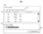
- FIG. 3 is a diagram showing an example of an alarm list screen.
- An alarm list screen 300 shown in FIG. 3 is a screen that displays all alarms notified by the automatic analyzer 100 .
- the alarm list screen 300 has an alarm list portion 301 , an alarm category selection portion 302 , an alarm content display portion 303 , and an alarm notification priority setting screen display button 304 .
- the alarm list section 301 displays alarm codes, alarm levels, and alarm messages for all alarms notified by the automatic analyzer 100 .
- An alarm code is a code for uniquely identifying an alarm.
- An alarm level is a level set according to the importance of the alarm.
- An alarm message is a message displayed on the display unit 202 to inform the user of the situation.
- Alarms are categorized by related functions, and the user checks alarms in each category by switching tabs in the alarm category selection section 302 . In this example, they are classified into four categories: "analysis”, “reagent”, “maintenance", and "system”. This allows the user to efficiently search for the desired alarm among many alarms.
- the alarm code, alarm level, alarm message, details, and countermeasures of the alarm are displayed in the alarm contents display section 303 .
- FIG. 4 shows an example of the alarm notification priority setting screen.
- the alarm notification priority setting screen 400 has an alarm list portion 401 , an alarm category selection portion 402 , a notification priority setting portion 403 , a required skill setting portion 404 , an alarm content display portion 405 and a save button 406 .
- the alarm list section 401 displays alarms output by the automatic analyzer 100 for which notification priority can be set by the user.
- the alarm for which the notification priority can be set by the user is a warning level alarm that does not require the sample measurement to be stopped even if an abnormality occurs and the user determines whether or not to continue the analysis.
- the alarm list portion 401 displays an alarm code, an alarm level, and an alarm message for an alarm whose alarm level is the caution level.
- the user can check alarms in each category by switching tabs in the alarm category selection section 402 . When the user selects an alarm whose detailed contents are to be confirmed, the alarm code, alarm level, alarm message, details, and countermeasures of the alarm are displayed in the alarm contents display section 405 .
- the alarm notification priority can be set for each alarm in the notification priority setting unit 403 .
- This embodiment shows an example of setting the alarm notification priority to one of two priorities, "normal” and "low", based on its urgency.
- the alarm whose notification priority is set to "normal” is immediately notified to the user.
- Alarms for which the notification priority is set to "low” are notified to the user by the alarm control unit 206 based on the notification control time period, notification method, etc. set on the alarm notification control setting screen, which will be described later. and the notification method are determined.
- the default notification priority setting value may be set to "normal", and the notification priority setting value for each alarm may be changed as necessary.
- the user sets the notification priority for each alarm one by one.
- a button or the like that can collectively set the notification priority may be provided.
- the user sets the notification priority to "low" for alarms for which the user does not want to receive notifications during a specific time period or for alarms for which the notification method is to be restricted. For example, for an alarm that the user considers to be less urgent because it does not affect sample measurement, the notification priority of the alarm is set to "low".
- Examples of alarms that do not affect measurement include an alarm that is notified when the volume of data stored in the operation unit PC 106 reaches a reference value, an alarm that recommends maintenance, and the like. Since none of the alarms immediately lead to the stoppage of the apparatus or interruption of measurement, there is no problem if the alarm is dealt with at a convenient time for the user's work.
- the user sets the skill level required to deal with each alarm.
- This embodiment shows an example in which the skill level is set in three stages (the higher the numerical value, the higher the level), but the form of skill level division is not particularly limited.
- a save button 406 is a button for saving the settings entered by the user on the alarm notification priority setting screen 400 .
- the information set by the notification priority setting unit 403 is stored as the notification priority data 203d in the storage unit 203
- the information set by the required skill setting unit 404 is stored as the required skill data 203f in the storage unit 203. The process to save is executed.
- FIG. 5 is a diagram showing an example of the alarm notification control setting screen.
- the alarm notification control setting screen 500 is a screen for setting a notification control time zone and a notification method for an alarm set to have a low notification priority.
- the alarm notification control setting screen 500 has an alarm notification control switching portion 501 , an alarm notification control time period setting screen display button 502 , a notification control time period list portion 503 , a notification method setting portion 504 , and a save button 505 .
- the alarm notification control switching unit 501 is a button for enabling or disabling the alarm notification control by the user.
- the alarm notification control is enabled, and when the user removes the check, the alarm notification control is disabled.
- the alarm notification control is to perform control for notifying the user of an alarm set to have a low notification priority according to the set notification control time zone and notification method.
- the alarm notification control is disabled, the user is immediately notified of the alarm regardless of the notification priority setting.
- an alarm notification control time period setting screen is displayed for the user to set the alarm notification control time period.
- the alarm notification control time zone setting screen will be described later.
- the days of the week, start times and end times of all notification control time periods set on the alarm notification control time period setting screen are displayed in the notification control time period list portion 503 .
- the number of set notification control time periods may be one or more.
- the notification method setting unit 504 selectively sets the notification method from a plurality of predetermined candidates when an alarm with a low notification priority occurs during the notification control time period.
- alarms set to have a low notification priority either "notify outside of notification control time" or “display only on screen (no notification sound)" is exemplified.
- the notification method is set to "notify outside of the notification control time”
- the automatic analyzer 100 will not notify the user during the notification control time. Suspend the alarm notification and notify the alarm after the notification control time period. If multiple alarms occur during the notification control time period, they are collectively notified.
- the notification method When the notification method is set to "display only on the screen (no notification sound)", when an alarm with a low notification priority occurs during the notification control time period, the automatic analyzer 100 In contrast to notification of an alarm by a notification sound and a screen, a screen for notifying the occurrence of an alarm is displayed only on the display unit 202 without generating a notification sound.
- the notification method is not limited to the above examples, and includes various examples.
- a save button 505 is a button for saving the notification control time zone and notification method set on the alarm notification control setting screen 500 .
- the notification control time period information set on the alarm notification control time period setting screen is stored as the notification control time period data 203c in the storage unit 203, and the information set by the notification method setting unit 504 is stored in the storage unit 203. is executed as the notification method data 203e.
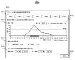
- FIG. 6 is a diagram showing an example of the alarm notification control time zone setting screen.
- the alarm notification control time period setting screen 600 has a day of the week selection section 601 , a busyness prediction display section 602 , a busyness level threshold setting section 603 , a notification control time period display section 604 , a user setting section 605 and an OK button 606 .
- the day of the week selection section 601 is used to switch the screen for setting the notification control time zone for each day of the week.
- This embodiment shows an example of setting the notification control time period for Monday.
- the busyness prediction display unit 602 displays the degree of busyness predicted by the prediction calculation unit 204 so that the degree of busyness for each time period can be easily recognized.
- the user sets the threshold value of the busyness degree in the busyness degree threshold value setting unit 603, which will be described later, the setting can be performed while confirming the busy state for each time zone.
- the display format is not limited to the format shown in FIG.
- the user sets a busyness threshold in the busyness threshold setting unit 603 .
- the prediction calculation unit 204 determines a time zone in which the predicted value of the busyness exceeds a set threshold as a busy time zone.
- a busy time zone For example, an example is shown in which the threshold for the busyness degree is set to 60%, and the busy time zone is from 8:30 to 12:00.
- FIG. 6 shows a case where there is only one busy time zone, but there may be multiple time zones. If the busyness threshold is not set, the busy time zone is not calculated.
- the time period determined to be the busy time period is displayed in the notification control time period display section 604 as the notification control time period.
- the notification control time period is automatically reset even when the trend of increase or decrease in the number of samples changes, so the user can saves you the trouble of having to change the settings.
- the busy time period predicted from the past measurement history is automatically reset even when the trend of increase or decrease in the number of samples changes, so the user can saves you the trouble of having to change the settings.
- the notification control time period is automatically reset even when the trend of increase or decrease in the number of samples changes, so the user can saves you the trouble of having to change the settings.
- the busy state for each day of the week it is possible to cope with the difference in inspection work and number of specimens depending on the day of the week.
- the user setting section 605 is used when the user sets the notification control time period.
- the user inputs the start time and end time of the notification control time period to the user setting section 605 .
- the decision button 606 is a button for registering the notification control time period set on the alarm notification control time period setting screen 600 in the notification control time period list section 503 of the alarm notification control setting screen 500 . Also, when the user presses the decision button 606 , the alarm notification control time zone setting screen 600 is closed and the alarm notification control setting screen 500 is displayed again.
- the procedure for setting the notification control time period using the alarm notification control setting screen 500 and the alarm notification control time period setting screen 600 is as follows.
- the user presses the alarm notification control time zone setting screen display button 502 on the alarm notification control setting screen 500 to display the alarm notification control time zone setting screen 600 .
- (1) Case of setting a busy time period as a notification control time period The user sets a busyness degree threshold using the busyness degree threshold setting unit 603 .
- the threshold value of the busyness degree is set, the time period determined as the busy time period by the prediction calculation unit 204 is displayed in the notification control time period display unit 604 as the notification control time period.
- the decision button 606 is pressed, the alarm notification control time period setting screen 600 is closed, and the notification control time period is registered in the notification control time period list section 503 of the alarm notification control setting screen 500 .
- the busy time zone can be set as the notification control time zone, or the notification control time zone set by the user can be set as the notification control time zone. Either one or both can be set. is also possible.
- the alarm control unit 206 acquires the notification priority data 203d stored in the storage unit 203 for the alarm corresponding to the anomaly, and issues a notification. The process proceeds to the priority determination step (S703).
- step S703 if the notification priority is low, the process proceeds to the step of obtaining notification control time zone information (S705), and the alarm control unit 206 , the notification control time zone data 203c stored in the storage unit 203 is obtained. Subsequently, the process proceeds to the step of determining the notification control time period (S706). In step S706, if the time at which the alarm was generated is outside the notification control time period, the alarm control unit 206 sends alarm information to the alarm notification unit 207 to notify the user of the alarm (S704).
- the alarm control unit 206 acquires the notification method data 203e stored in the storage unit 203 (S707). After that, the alarm control unit 206 determines the alarm notification time and notifies the alarm according to the set notification method (S708).
- the notification control time zone and notification method for alarms with low notification priority it is possible to notify the user of the alarm at the timing and notification method appropriate for the user. Since the user can focus on inspection work without being bothered by alarms with low notification priority, the work efficiency of inspection work can be improved.
- FIG. 8 is a diagram showing an example of the user information setting screen.
- the user information setting screen 800 has a user information registration section 801 , an alarm notification limit switching section 802 and a save button 803 .
- the user registers the user ID, user name, working days, working hours, and possessed skills of the user who uses the automatic analyzer 100 in the user information registration unit 801 .
- the alarm notification limit switching unit 802 is used to switch whether to enable or disable the alarm notification limit based on the skills possessed by the user who is on duty. For example, if the user checks the checkbox, the notification limit is enabled, and if the user unchecks the notification limit, the notification limit is disabled.
- the alarm control unit 206 compares the required skill set for the alarm with the registered skills of the user. , it is determined whether or not the user who can deal with the alarm is on duty, and whether or not to withhold notification of the alarm is determined. For example, if the person with the skill necessary for dealing with the alarm is outside working hours, the alarm control unit 206 withholds the notification of the alarm until the next working time of the person with the skill necessary for dealing with the alarm.
- the notification restriction will be explained using the user information shown in FIG. 8 as an example. For example, when an alarm for required skill 3 occurs at 5:00 on Monday, the user who is working at that time has skill "1", so the user who is working at that time can deal with the alarm. Can not. Since the next working hours of the user with skill 3 are 7:00 to 17:00 on Monday, the alarm will be notified after 7:00 on Monday.
- a save button 803 is a button for executing processing for saving the information set on the user information setting screen 800 in the user data 203g of the storage unit 203 .
- the alarm control unit 206 acquires the notification priority data 203d stored in the storage unit 203 for the alarm corresponding to the abnormality, and issues a notification. The process proceeds to the priority determination step (S903).
- the process proceeds to a step of determining whether or not a user possessing the skill required to deal with the alarm (hereinafter referred to as a skill possessing user) is within working hours (S907). If the skill-possessed user is within working hours, the process proceeds to the step of acquiring notification control time period information, and the alarm control unit 206 acquires the notification control time period from the notification control time period data 203c stored in the storage unit 203. (S909). If the skill-possessed user is outside working hours, the processing is suspended until the next working hours of the skill-possessed user (S908), and then the process proceeds to the step of acquiring notification control time zone information (S909).
- the alarm control unit 206 sends the alarm information to the alarm notification unit 207. and notify the user of an alarm (S904). If the time at which the alarm is to be notified falls within the notification control time period, the alarm control unit 206 acquires the notification method data 203e stored in the storage unit 203 (S911). After that, the alarm control unit 206 determines the alarm notification time and notifies the alarm according to the set notification method (S912).
- the alarm can be notified at the timing when the user can respond to the alarm, thereby reducing the burden on the user and improving the work efficiency of inspection work.
- the user sets the alarm notification priority, notification control time zone, notification method, etc. according to the operation of each facility. Then, when an alarm occurs during the notification control time period, the alarm control unit determines the notification time and notification method based on the notification priority of the alarm. As a result, it is possible to notify the user of the alarm in accordance with the operation of each facility, so that the user can be notified of the alarm at the timing and the notification method suitable for the user. In addition, since the user does not need to interrupt the inspection work to deal with alarms with low urgency, the work efficiency of the entire inspection room can be improved.
- the present invention is not limited to the above-described embodiments, and includes various modifications.
- the above-described embodiments have been described in detail in order to explain the present invention in an easy-to-understand manner, and are not necessarily limited to those having all the described configurations.
- the storage unit 203 does not need to store the notification method data 203e.
- an example of setting and registering information for controlling alarm notification in the operation unit PC 106 has been described, but the present invention is not limited to this.
- these data may be stored from a management server connected to the operation unit PC of each automatic analyzer.
- a management server connected to the operation unit PC of each automatic analyzer.
- the user data 203g the date and time of work of the user who works in the clinical laboratory and the possessed skills may be registered without specifying the automatic analyzer.
- DESCRIPTION OF SYMBOLS 100 Automatic analyzer 101... Specimen loading part 102... Specimen information reading part 103... Transport line 104... Analysis part 105... Specimen storage part 106... Operation part PC, 201... Input part, 202... Display part 203...storage unit 203a...measurement history data 203b...busy degree data 203c...notification control time period data 203d...notification priority data 203e...notification method data 203f...required skill data 203g...user data, 204... Predictive calculation unit 205... Anomaly detection unit 206... Alarm control unit 207... Alarm notification unit 300... Alarm list screen 301... Alarm list unit 302... Alarm category selection unit 303...
- Alarm content display unit 304 Alarm notification priority setting screen display button 400... Alarm notification priority setting screen 401... Alarm list section 402... Alarm category selection section 403... Notification priority setting section 404... Required skill setting section 405... Alarm content display part 406...Save button 500...Alarm notification control setting screen 501...Alarm notification control switching part 502...Alarm notification control time period setting screen display button 503...Notification control time period list part 504...Notification Method setting part 505... Save button 600... Alarm notification control time period setting screen 601... Day of the week selection part 602... Busy prediction display part 603... Busy level threshold setting part 604... Notification control time period display part 605 User setting unit 606 OK button 800 User information setting screen 801 User information registration unit 802 Alarm notification limit switching unit 803 Save button
Abstract
緊急性の低いアラームについて、検査業務の状況に基づき、ユーザにとって適切なタイミング及び通知方法により通知する自動分析装置を提供する。自動分析装置は、アラームに設定された通知優先度を示す通知優先度データ203dと、所定の通知優先度が設定されたアラームについてアラームの通知方法を制御する時間帯である通知制御時間帯を示す通知制御時間帯データ203cとを記憶しており、検知された異常に対応するアラームが、通知優先度データを用いて所定の通知優先度が設定されたアラームであるか否かを判定し、当該アラームが所定の通知優先度が設定されたアラームであると判定された場合には、通知制御時間帯データに示される当該アラームの通知制御時間帯の内外に応じて当該アラームの通知方法を制御する。
Description
本発明は、自動分析装置及び自動分析装置のアラーム通知方法に関する。
血液や尿等の検体の特定成分を定量・定性分析する自動分析装置では、稼動時に異常が発生した場合、装置画面への表示や警告音・警告灯により異常の発生を通知する。
自動分析装置におけるアラーム通知に関する技術の一例として、特許文献1(国際公開第2017/145601号)には、自動分析装置の装置状態に関する情報と、予め定めた基準とに基づいて、異常検出部により検出された各異常項目について、異常が生じた場合にその旨を通知する異常発生アラームと、異常への対処が可能な装置状態となった場合にユーザにその旨を通知する対処可能アラームの少なくとも2つのアラームを計画することが開示されている。
一般的に、自動分析装置が通知するアラームは、発生した異常が装置や測定に影響を与える程度に応じて、緊急停止、測定不可、注意等のレベル分けがされている。緊急停止、測定不可レベルの異常発生によるアラームが通知された場合、検体測定の継続が不可能な状態であるため、早急に対処が必要である。一方、注意レベルの異常発生によるアラームが通知された場合、装置の動作は止まらないため、ユーザが測定を続けるか否かを判断する。
注意レベルのアラームには、対処のために検体測定を停止する必要のないアラームも存在する。しかしながら、アラームが通知されるとユーザは、アラームの内容を確認するために作業の手を止める必要がある。検査業務の繁忙時間等において、緊急性の低いアラーム通知によりユーザの作業を中断させてしまうことは、業務効率の低下を引き起こす。
特許文献1に開示されている自動分析装置は、異常への対処が可能な装置状態であると判定する判定基準をアラームごとに予め設定し、異常発生時と対処可能時の二段階でアラーム通知を行うことにより、ユーザがタイムリーにアラームに対処することができる。
一方で、アラーム通知時のユーザの状況やアラームごとの緊急性は考慮されていないという問題点がある。例えば、検査業務の繁忙時間においてユーザは、測定の継続に影響を与えるアラームに対しては早急に対処する必要がある。緊急性の低いアラームは、ユーザの都合の良い時間に対処すればよいので非繁忙時間に通知をすれば、繁忙時間におけるアラームの数を減らすことができ、ユーザは検査業務に注力することができる。
また、装置使用に習熟していないユーザが装置を使用中にアラームが発生した場合、当該ユーザは、アラームに対処することができないため、別ユーザに問合せを行う等により検査業務を中断する可能性がある。そのため、緊急性の低いアラームにおいては、対処可能なユーザの勤務時間内に通知をすることで、不要な問い合わせ等の手間を軽減することができる。
本発明の目的は、緊急性の低いアラームについて、検査業務の状況に基づき、ユーザにとって適切なタイミング及び通知方法により通知する自動分析装置を提供することにある。
上記目的を達成するために、本発明の一実施の態様である、検体の特定成分を定量・定性分析する自動分析装置は、異常を検知する異常検知部と、異常検知部により検知された異常についてのアラームの通知を制御するアラーム制御部と、アラームをユーザに通知するアラーム通知部と、アラーム制御部がアラームの通知を制御するためのデータを記憶する記憶部とを有し、記憶部は、アラームに設定された通知優先度を示す通知優先度データと、所定の通知優先度が設定されたアラームについてアラームの通知方法を制御する時間帯である通知制御時間帯を示す通知制御時間帯データとを記憶しており、アラーム制御部は、異常検知部が検知した異常に対応するアラームが、通知優先度データにより所定の通知優先度が設定されたアラームであると判定される場合には、通知制御時間帯データに示される当該アラームの通知制御時間帯の内外に応じて、アラーム通知部による当該アラームの通知方法を制御する。
本発明によれば、緊急性の低いアラームについて、検査業務の状況に基づき、ユーザにとって適切なタイミング及び通知方法により通知することができるため、検査室全体の作業効率を向上させることができる。その他の課題と新規な特徴は、本明細書の記述および添付図面から明らかになるであろう。
本発明の実施例を図面に基づいて説明する。なお、本明細書で用いる図面において、同一または対応する構成要素には同一または類似の符号を付け、これらの構成要素については繰り返しの説明を省略する場合がある。
まず、本発明の一実施例に係る自動分析装置について図1を用いて説明する。図1は、本実施例に係る自動分析装置の概略構成図である。自動分析装置100は、検体搬入部101、検体情報読取部102、搬送ライン103、分析部104、検体収納部105、操作部PC106等から構成されている。
検体搬入部101は、自動分析装置100において、患者検体やコントロール検体、精度管理検体が入った検体容器を検体ラックに設置して搬入するユニットである。
各検体容器には識別情報を示すバーコードやRFID等のタグが付与されており、検体情報読取部102において識別情報を読み取ることで検体の識別を行う。読み取った検体の情報は操作部PC106に送られる。
搬送ライン103は、検体搬入部101から供給された検体ラックをユーザからの分析依頼に従って対象となる分析部104へ搬送したり、分析完了後の検体を検体収納部105へ搬送したりするユニットである。
分析部104は、生化学分析や免疫分析、電解質分析等を行う分析装置から構成され、検体の分析を実施するユニットである。本実施例では、1つの分析装置を備えた自動分析装置を例に挙げて説明するが、1つ以上の分析装置が含まれる自動分析装置であればよい。また、分析部104の構成は特に限定されず、複数の分析装置による構成の場合、同一の分析装置でも異なる分析装置の組み合わせでもよい。
検体収納部105は、分析完了後の検体を収納するユニットである。
操作部PC106は、CPUやメモリなどを備えたコンピュータである。操作部PC106は、有線或いは無線のネットワーク回線によって、自動分析装置100の各機器と通信可能に接続され、プログラムやユーザにより入力されたデータに基づき自動分析装置100の各機器の動作を制御したり、装置状態や検体の分析状況を監視したりする。なお、操作部PC106は、病院や検査室システム全体を制御する上位ホストシステムや自動分析装置100を操作するユーザが保持しているPCやタブレット、モバイル等の端末と接続されていてもよい。
図2は、自動分析装置100が備える操作部PC106の機能ブロック図である。図2では、操作部PC106におけるアラーム機能に関連する部分を抜き出して表しており、その他の制御機能については省略してある。操作部PC106は、入力部201、表示部202、記憶部203、予測演算部204、異常検知部205、アラーム制御部206、アラーム通知部207等により構成されている。
入力部201は、キーボードやマウス、タッチパネル等ユーザが自動分析装置100に対して指示や情報を入力するデバイスである。
表示部202は、各種操作画面やアラーム情報等を表示するディスプレイである。表示部202がタッチパネル型である場合には、入力部201の機能を兼ねる。
記憶部203は、自動分析装置100を制御するためのプログラムと、測定履歴データ203a、繁忙度データ203b、通知制御時間帯データ203c、通知優先度データ203d、通知方法データ203e、必要スキルデータ203f、ユーザデータ203gを記憶している。測定履歴データ203aは、自動分析装置100の検体情報読取部102で読み取られた検体の読取年月日、読取時間等のデータである。繁忙度データ203bは、後述する予測演算部204で予測された各時間の繁忙度及び繁忙時間帯のデータである。通知制御時間帯データ203cは、予測演算部204で予測された繁忙時間帯に基づいて設定された通知制御時間帯やユーザが設定した通知制御時間帯のデータである。通知優先度データ203dは、各アラームに設定された通知優先度のデータである。通知方法データ203eは、ユーザが設定したアラームの通知方法のデータである。必要スキルデータ203fは、ユーザがアラームに設定したアラームの対処に必要なスキルのデータである。ユーザデータ203gは、自動分析装置100を使用するユーザのユーザID、ユーザ名、勤務曜日、勤務時間、保有スキル等のデータである。
予測演算部204は、記憶部203に記憶された測定履歴データ203aのデータから各時間帯の繁忙度を予測したり、予測した繁忙度から検査業務の繁忙時間帯を設定したりする。繁忙度の予測方法については後述する。
異常検知部205は、自動分析装置100に付属するセンサ等からの情報に基づいて、自動分析装置100における異常を検出する。
アラーム制御部206は、異常検知部205により検出された各異常項目について記憶部203に記憶された情報に基づいてアラームの通知時刻や通知方法を決定する。
アラーム通知部207は、表示部202に異常の発生を知らせるアラーム画面を表示したり、自動分析装置100に備えているスピーカーから警告音を発したり、警告灯を点灯させたりすることによってアラームをユーザに報知する。
予測演算部204による繁忙度の予測方法について説明する。記憶部203に記憶されている測定履歴データ203aのデータから、過去の測定検体数を曜日や時間帯ごとに集計し、その平均値から曜日ごとの各時間帯における検体数の予測値を算出する。一日のうちで最も検体数が多いと予測される時間帯を繁忙度100%とする。最も検体数が多いと予測される時間帯の検体数と各時間帯における予測検体数とを比較することにより繁忙度(%)が算出される。繁忙度は以下の式で算出される。
繁忙度(%)=ある時間帯の予測検体数/一日のうちで最も検体数が多いと予測される時間帯の検体数×100
例えば、最も検体数が多い時間帯の予測検体数が300検体、12:00から13:00の予測検体数が150検体であった場合、12:00から13:00の繁忙度は、50%と算出される。
繁忙度(%)=ある時間帯の予測検体数/一日のうちで最も検体数が多いと予測される時間帯の検体数×100
例えば、最も検体数が多い時間帯の予測検体数が300検体、12:00から13:00の予測検体数が150検体であった場合、12:00から13:00の繁忙度は、50%と算出される。
予測に用いる情報は、過去の測定検体数に限定されず、繁忙状況に影響を与えうる要素を上記で算出した結果に反映してもよい。
一例として、検査業務を行う作業者の人数を繁忙状況に影響を与えうる要素として用いる場合について説明する。一般的に検査室の業務ではシフト制がとられていることが多く、時間帯によって作業者の人数が異なることがある。そのため、各時間における作業者の人数を検体数から予測した繁忙度に反映することで、より実際の検査室の状況に即した予測が可能になる。各時間における作業者の人数は、記憶部203のユーザデータ203gに記憶されたユーザの勤務時間から算出することができる。
例えば、7:00~8:00の作業者は2人、8:00~9:00の作業者は4人であったとする。いずれの時間帯も100検体分の作業を行うと仮定すると、7:00~8:00の一人当たりの負担は50検体であるのに対し、8:00~9:00の一人当たりの負担は25検体となり、前者は後者に比べて作業者一人当たりにかかる負担は2倍となる。そこで、作業者の人数に応じて係数を設定する。例えば、4人で作業する場合の係数を1とすると、2人で作業する場合の係数は2となる。一時間当たりの検体数に前記係数をかけることにより、作業者の人数を反映した一時間当たりの検体数は以下のように算出される。
7:00~8:00(2人で作業する場合):100×2=200検体
8:00~9:00(4人で作業する場合):100×1=100検体
以上より、8:00~9:00における繁忙度は、7:00~8:00における繁忙度に対して50%の繁忙度であると算出される。同様にして、各時間における予測検体数に作業者の人数に応じた係数をかけることで、作業者の人数による作業量の変化の影響を繁忙度に反映することができる。
7:00~8:00(2人で作業する場合):100×2=200検体
8:00~9:00(4人で作業する場合):100×1=100検体
以上より、8:00~9:00における繁忙度は、7:00~8:00における繁忙度に対して50%の繁忙度であると算出される。同様にして、各時間における予測検体数に作業者の人数に応じた係数をかけることで、作業者の人数による作業量の変化の影響を繁忙度に反映することができる。
繁忙状況に影響を与えうる情報は上記した例に限定されるものではなく、様々な例が含まれる。
図3は、アラーム一覧画面の例を示す図である。図3に示すアラーム一覧画面300は、自動分析装置100で通知される全てのアラームを表示する画面である。アラーム一覧画面300は、アラームリスト部301、アラームカテゴリ選択部302、アラーム内容表示部303、アラーム通知優先度設定画面表示ボタン304を有している。
アラームリスト部301には、自動分析装置100で通知される全てのアラームについてアラームコード、アラームレベル、アラームメッセージが表示される。アラームコードはアラームを一意に特定するためのコードである。アラームレベルはそのアラームの重要性に従って設定されるレベルである。アラームメッセージは事態をユーザに知らせるために表示部202に表示されるメッセージである。また、アラームは関連する機能ごとにカテゴリ分けされており、ユーザは、アラームカテゴリ選択部302のタブを切り替えることで各カテゴリのアラームを確認する。この例では、「分析」、「試薬」、「メンテナンス」、「システム」の4つのカテゴリに分類されている。これにより、ユーザは数多くのアラームの中から目的のアラームを効率的に探すことができる。ユーザが詳細な内容を確認したいアラームを選択すると、アラーム内容表示部303に当該アラームのアラームコード、アラームレベル、アラームメッセージ、詳細、対処法が表示される。
ユーザがアラーム通知優先度設定画面表示ボタン304を押下すると、アラーム通知優先度設定画面が表示される。図4に、アラーム通知優先度設定画面の例を示す。アラーム通知優先度設定画面400は、アラームリスト部401、アラームカテゴリ選択部402、通知優先度設定部403、必要スキル設定部404、アラーム内容表示部405、保存ボタン406を有している。
アラームリスト部401には、自動分析装置100で出力されるアラームのうち、ユーザによる通知優先度が設定可能なアラームが表示される。ここで、ユーザによる通知優先度が設定可能なアラームとは、異常が発生しても検体測定を停止する必要はなく、ユーザが分析を続けるか否かを判断する注意レベルのアラームである。アラームリスト部401には、アラームレベルが注意レベルであるアラームについて、アラームコード、アラームレベル、アラームメッセージが表示される。ユーザは、アラームカテゴリ選択部402のタブを切り替えることで各カテゴリのアラームを確認できる。ユーザが詳細な内容を確認したいアラームを選択すると、アラーム内容表示部405に当該アラームのアラームコード、アラームレベル、アラームメッセージ、詳細、対処法が表示される。
アラームの通知優先度は、通知優先度設定部403において、アラームごとに設定可能である。本実施例では、アラームの通知優先度を、その緊急性に基づいて「通常」と「低い」の二つの優先度からいずれかを設定する例を示す。自動分析装置100でアラームが発生した場合、通知優先度が「通常」と設定されたアラームは、即時ユーザに通知される。通知優先度が「低い」と設定されたアラームは、後述するアラーム通知制御設定画面において設定された通知制御時間帯や通知方法等に基づき、アラーム制御部206により当該アラームをユーザに通知する通知時刻や通知方法が決定される。通知優先度のデフォルトの設定値を「通常」としておき、必要に応じて、アラームごとの通知優先度の設定値を変更するようにしてもよい。また、図4に示した例では、アラームごとの通知優先度をユーザが一つ一つ設定する例を示しているが、ユーザの設定の手間を軽減させるために、特定のカテゴリのアラーム全ての通知優先度を一括で設定できるボタン等を設けてもよい。
ユーザは、特定の時間帯に通知を受け取ることを望まないアラームや通知方法を制限したいアラームの通知優先度を「低い」に設定する。例えば、検体の測定に影響を与えないため緊急性が低いとユーザが考えるアラームについて、アラームの通知優先度を「低い」に設定する。測定に影響を与えないアラームの例として、操作部PC106で記憶するデータの容量が基準値に達した際に通知されるアラームやメンテナンス推奨のアラーム等が挙げられる。いずれのアラームもすぐに装置の停止や測定の中断につながらないため、ユーザの業務の都合のよい時間に対処すれば問題ないアラームである。
必要スキル設定部404において、ユーザはアラームごとに対処に必要なスキルレベルを設定する。本実施例では、スキルレベルを3段階で設定する例(数値が大きい程、高いレベルであるとする)を示しているが、スキルレベルのレベル分けの形式は特に限定されない。
保存ボタン406は、アラーム通知優先度設定画面400でユーザが入力した設定内容を保存するためのボタンである。保存ボタン406を押下することにより、通知優先度設定部403で設定した情報を記憶部203の通知優先度データ203dとして、必要スキル設定部404で設定した情報を記憶部203の必要スキルデータ203fとして保存する処理が実行される。
図5は、アラーム通知制御設定画面の例を示す図である。アラーム通知制御設定画面500は、通知優先度が低いと設定されたアラームの通知制御時間帯や通知方法を設定する画面である。アラーム通知制御設定画面500は、アラーム通知制御切替部501、アラーム通知制御時間帯設定画面表示ボタン502、通知制御時間帯リスト部503、通知方法設定部504、保存ボタン505を有している。
アラーム通知制御切替部501は、ユーザがアラーム通知制御を有効にする又は無効にするかを切替えるボタンである。ここでは、ユーザがチェックボックスにチェックを入れるとアラーム通知制御が有効になり、チェックを外すとアラーム通知制御が無効になる。アラーム通知制御とは、通知優先度が低いと設定されたアラームについて、設定された通知制御時間帯や通知方法にしたがってアラームをユーザに通知する制御を行うことである。アラーム通知制御が無効の場合には、通知優先度の設定に関わらず、アラームは即時ユーザに通知される。
ユーザがアラーム通知制御時間帯設定画面表示ボタン502を押下すると、ユーザがアラーム通知制御時間帯を設定するためのアラーム通知制御時間帯設定画面が表示される。アラーム通知制御時間帯設定画面については後述する。アラーム通知制御時間帯設定画面において設定された全ての通知制御時間帯の曜日、開始時間及び終了時間が、通知制御時間帯リスト部503に表示される。通知制御時間帯の設定数は一つ以上であればよい。
通知方法設定部504は、通知制御時間帯に通知優先度が低いと設定されたアラームが発生した場合の通知方法を予め定めた複数の候補から選択的に設定するものである。本実施例では、通知優先度が低いと設定されたアラームは、「通知制御時間外に通知する」もしくは、「画面のみに表示する(通知音なし)」いずれかを選択する場合を例示している。例えば、通知方法を「通知制御時間外に通知する」と設定すると、通知制御時間帯に通知優先度が低いと設定されたアラームが発生した場合、自動分析装置100は、通知制御時間帯では当該アラームの通知を保留し、通知制御時間帯以降に当該アラームを通知する。通知制御時間帯に複数のアラームが発生した場合には、それらをまとめて通知する。通知方法を「画面のみに表示する(通知音なし)」と設定すると、通知制御時間帯に通知優先度が低いと設定されたアラームが発生した場合、自動分析装置100は、通知制御時間帯以外では通知音と画面とでアラームを通知するのに対して、通知音を出さず表示部202のみにアラームの発生を知らせる画面を表示する。なお、通知方法は上記した例に限定されるものではなく、様々な例が含まれる。
保存ボタン505は、アラーム通知制御設定画面500で設定した通知制御時間帯と通知方法を保存するためのボタンである。保存ボタン505を押下することにより、アラーム通知制御時間帯設定画面において設定した通知制御時間帯情報を記憶部203の通知制御時間帯データ203cとして、通知方法設定部504で設定した情報を記憶部203の通知方法データ203eとして保存する処理が実行される。
図6は、アラーム通知制御時間帯設定画面の例を示す図である。アラーム通知制御時間帯設定画面600は、曜日選択部601、繁忙予測表示部602、繁忙度閾値設定部603、通知制御時間帯表示部604、ユーザ設定部605、決定ボタン606を有している。
曜日選択部601は、通知制御時間帯を設定する画面を曜日ごとに切替えるために使用する。本実施例では、月曜日の通知制御時間帯を設定する例を示している。
繁忙予測表示部602は、予測演算部204が予測した繁忙度を時間帯ごとの繁忙度が認識しやすいように表示する。これにより、後述する繁忙度閾値設定部603にて、ユーザが繁忙度の閾値を設定する際に時間帯ごとの繁忙状況を確認しながら設定を行うことができる。ここでは、時間帯ごとの繁忙度の変化を線グラフで表示しているが、表示形式は図6に示した形態に限定されない。
ユーザは繁忙度閾値設定部603において、繁忙度の閾値を設定する。予測演算部204は、繁忙度の予測値が設定された閾値を超えている時間帯を繁忙時間帯と判定する。ここでは、繁忙度の閾値を60%に設定した例を示しており、8:30~12:00が繁忙時間帯となる。図6では、繁忙時間帯が一つの時間帯のみの場合を示しているが、複数の時間帯となる場合もある。繁忙度の閾値を設定しない場合は、繁忙時間帯は算出されない。
繁忙時間帯と判定された時間帯は、通知制御時間帯として通知制御時間帯表示部604に表示される。過去の測定履歴から予測された繁忙時間帯を通知制御時間帯として設定することにより、検体数の増減の傾向等が変化した場合においても自動で通知制御時間帯の再設定が行われるため、ユーザが設定の変更を行う手間を省くことができる。また、曜日ごとに繁忙状況を予測することで、曜日による検査業務や検体数の違いがある場合にも対応することができる。
ユーザ設定部605は、ユーザが通知制御時間帯を設定する場合に使用するものである。ユーザは、ユーザ設定部605に通知制御時間帯の開始時間及び終了時間を入力する。
決定ボタン606は、アラーム通知制御時間帯設定画面600で設定した通知制御時間帯をアラーム通知制御設定画面500の通知制御時間帯リスト部503に登録するためのボタンである。また、ユーザが決定ボタン606を押下すると、アラーム通知制御時間帯設定画面600は閉じられ、アラーム通知制御設定画面500に戻る。
アラーム通知制御設定画面500及びアラーム通知制御時間帯設定画面600を用いた通知制御時間帯の設定手順は以下の通りである。
まず、ユーザはアラーム通知制御設定画面500のアラーム通知制御時間帯設定画面表示ボタン502を押下し、アラーム通知制御時間帯設定画面600を表示させる。
(1)繁忙時間帯を通知制御時間帯に設定する場合
ユーザは、繁忙度閾値設定部603で繁忙度の閾値を設定する。繁忙度の閾値を設定すると、予測演算部204で繁忙時間帯と判定された時間帯は、通知制御時間帯として通知制御時間帯表示部604に表示される。その後、決定ボタン606を押下すると、アラーム通知制御時間帯設定画面600は閉じられ、通知制御時間帯はアラーム通知制御設定画面500の通知制御時間帯リスト部503に登録される。
ユーザは、繁忙度閾値設定部603で繁忙度の閾値を設定する。繁忙度の閾値を設定すると、予測演算部204で繁忙時間帯と判定された時間帯は、通知制御時間帯として通知制御時間帯表示部604に表示される。その後、決定ボタン606を押下すると、アラーム通知制御時間帯設定画面600は閉じられ、通知制御時間帯はアラーム通知制御設定画面500の通知制御時間帯リスト部503に登録される。
(2)ユーザ設定の通知制御時間帯を設定する場合
ユーザは、ユーザ設定部605に通知制御時間帯の開始時間及び終了時間を入力する。その後、決定ボタン606を押下すると、ユーザ設定部605に入力された通知制御時間帯はアラーム通知制御設定画面500の通知制御時間帯リスト部503に登録される。
ユーザは、ユーザ設定部605に通知制御時間帯の開始時間及び終了時間を入力する。その後、決定ボタン606を押下すると、ユーザ設定部605に入力された通知制御時間帯はアラーム通知制御設定画面500の通知制御時間帯リスト部503に登録される。
通知制御時間帯は、繁忙時間帯を通知制御時間帯に設定するもしくは、ユーザ設定の通知制御時間帯を通知制御時間帯に設定することができ、どちらかのみ設定することも、両方設定することも可能である。
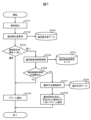
自動分析装置100において、アラーム通知制御を有効にした場合の異常検出からアラーム通知までのフローについて図7を用いて説明する。
異常検知部205が自動分析装置100で発生した異常を検出すると(S701)、アラーム制御部206は、当該異常に対応するアラームについて記憶部203に記憶される通知優先度データ203dを取得し、通知優先度の判定ステップに進む(S703)。
(1)通知優先度が通常のアラーム場合
通知優先度の判定の結果(S703)、通知優先度が通常であった場合には、アラーム制御部206は、アラーム通知部207にアラーム情報を送り、ユーザにアラームを通知する(S704)。
通知優先度の判定の結果(S703)、通知優先度が通常であった場合には、アラーム制御部206は、アラーム通知部207にアラーム情報を送り、ユーザにアラームを通知する(S704)。
(2)通知優先度が低いアラームの場合
通知優先度の判定の結果(S703)、通知優先度が低い場合には、通知制御時間帯情報取得のステップに進み(S705)、アラーム制御部206は、記憶部203に記憶される通知制御時間帯データ203cを取得する。続いて、通知制御時間帯の判定を行うステップに進む(S706)。ステップS706において、アラームが発生した時刻が通知制御時間帯の時間外である場合は、アラーム制御部206はアラーム通知部207にアラーム情報を送り、ユーザにアラームを通知する(S704)。これに対して、ステップS706においてアラームが発生した時刻が通知制御時間帯の時間内であった場合、アラーム制御部206は、記憶部203に記憶される通知方法データ203eを取得する(S707)。その後、アラーム制御部206は、アラームの通知時刻を決定し、設定された通知方法に従ってアラームを通知する(S708)。
通知優先度の判定の結果(S703)、通知優先度が低い場合には、通知制御時間帯情報取得のステップに進み(S705)、アラーム制御部206は、記憶部203に記憶される通知制御時間帯データ203cを取得する。続いて、通知制御時間帯の判定を行うステップに進む(S706)。ステップS706において、アラームが発生した時刻が通知制御時間帯の時間外である場合は、アラーム制御部206はアラーム通知部207にアラーム情報を送り、ユーザにアラームを通知する(S704)。これに対して、ステップS706においてアラームが発生した時刻が通知制御時間帯の時間内であった場合、アラーム制御部206は、記憶部203に記憶される通知方法データ203eを取得する(S707)。その後、アラーム制御部206は、アラームの通知時刻を決定し、設定された通知方法に従ってアラームを通知する(S708)。
これにより、通知優先度の低いアラームについて、通知制御時間帯及び通知方法を設定することで、ユーザにとって適切なタイミング及び通知方法によりアラームをユーザに通知することができる。ユーザは通知優先度の低いアラームに煩わされることなく検査業務に注力することができるため、検査業務の作業効率を向上させることができる。
続いて、ユーザの保有スキルによってアラームの通知制御を行う例を説明する。
例えば、装置使用に習熟していないユーザが装置を使用中にアラームが発生した場合、当該ユーザは、アラームに対処することができないため、別ユーザに問合せを行う等の必要が生じる場合がある。そのため、緊急性の低いアラームにおいては、勤務中のユーザの保有スキルに応じた制限を設定することで、不要な問い合わせ等の手間を軽減することが期待できる。
図8は、ユーザ情報設定画面の例を示す図である。ユーザ情報設定画面800は、ユーザ情報登録部801、アラーム通知制限切替部802、保存ボタン803を有している。
ユーザは、ユーザ情報登録部801に自動分析装置100を使用するユーザのユーザID、ユーザ名、勤務曜日、勤務時間、保有スキルを登録する。
アラーム通知制限切替部802は、勤務中のユーザの保有スキルによるアラームの通知制限を有効にする、または無効にするかを切替える場合に用いる。例えば、ユーザがチェックボックスにチェックを入れると通知制限が有効になり、チェックを外すと通知制限が無効になる。通知制限を有効にした場合、通知優先度が低いに設定されたアラームが発生すると、アラーム制御部206は、当該アラームに設定された必要スキルと登録されているユーザの保有スキルとを照合することで、当該アラームの対処が可能なユーザが勤務中か否かを判定し、当該アラームの通知を保留するか否かを決定する。例えば、アラームの対処に必要なスキル保有者が勤務時間外である場合、アラーム制御部206は、アラームの対処に必要なスキル保有者の次回の勤務時間になるまでアラームの通知を保留する。
通知制限について、図8に例示したユーザ情報を例に説明する。例えば、月曜日の5:00に必要スキル3のアラームが発生した場合、当該時間に勤務中のユーザの保有スキルは「1」であるため、当該時間に勤務中のユーザではアラームに対処することができない。スキル3保有ユーザの次の勤務時間は、月曜日の7:00~17:00であるため、当該アラームは月曜日の7:00以降に通知される。
保存ボタン803はユーザ情報設定画面800で設定した情報を記憶部203のユーザデータ203gに保存する処理を実行するためのボタンである。
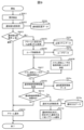
ユーザスキルに基づく通知制限を有効にした場合の異常検出からアラーム通知までのフローについて図9を用いて説明する。
異常検知部205が自動分析装置100で発生した異常を検出すると(S901)、アラーム制御部206は、当該異常に対応するアラームについて記憶部203に記憶される通知優先度データ203dを取得し、通知優先度の判定ステップに進む(S903)。
(1)通知優先度が通常のアラーム場合
通知優先度の判定の結果(S903)、通知優先度が通常であった場合には、アラーム制御部206は、アラーム通知部207にアラーム情報を送り、ユーザにアラームを通知する(S904)。
通知優先度の判定の結果(S903)、通知優先度が通常であった場合には、アラーム制御部206は、アラーム通知部207にアラーム情報を送り、ユーザにアラームを通知する(S904)。
(2)通知優先度が低いアラームの場合
通知優先度の判定の結果(S903)、通知優先度が低い場合には、アラームに設定された必要スキルを取得するステップに進み(S905)、アラーム制御部206は、記憶部203に記憶される必要スキルデータ203fから当該アラームの必要スキルを取得する。続いて、ユーザ情報取得のステップに進み(S906)、アラーム制御部206は、記憶部203に記憶されるユーザデータ203gからユーザの勤務曜日、勤務時間及び保有スキルを取得する。その後、アラームの対処に必要なスキルを保有するユーザ(以下では、スキル保有ユーザという)が勤務時間内か否かを判定するステップに進む(S907)。スキル保有ユーザが勤務時間内である場合は、通知制御時間帯情報を取得するステップに進み、アラーム制御部206は、記憶部203に記憶される通知制御時間帯データ203cから通知制御時間帯を取得する(S909)。スキル保有ユーザが勤務時間外である場合は、スキル保有ユーザの次の勤務時間になるまで保留し(S908)、その後、通知制御時間帯情報を取得するステップに進む(S909)。続いて、通知制御時間帯の判定を行うステップ(S910)において、アラームを通知しようとする時刻が通知制御時間帯の時間外である場合は、アラーム制御部206はアラーム通知部207にアラーム情報を送り、ユーザにアラームを通知する(S904)。アラームを通知しようとする時刻が、通知制御時間帯の時間内であった場合、アラーム制御部206は、記憶部203に記憶される通知方法データ203eを取得する(S911)。その後、アラーム制御部206は、アラームの通知時刻を決定し、設定された通知方法に従ってアラームを通知する(S912)。
通知優先度の判定の結果(S903)、通知優先度が低い場合には、アラームに設定された必要スキルを取得するステップに進み(S905)、アラーム制御部206は、記憶部203に記憶される必要スキルデータ203fから当該アラームの必要スキルを取得する。続いて、ユーザ情報取得のステップに進み(S906)、アラーム制御部206は、記憶部203に記憶されるユーザデータ203gからユーザの勤務曜日、勤務時間及び保有スキルを取得する。その後、アラームの対処に必要なスキルを保有するユーザ(以下では、スキル保有ユーザという)が勤務時間内か否かを判定するステップに進む(S907)。スキル保有ユーザが勤務時間内である場合は、通知制御時間帯情報を取得するステップに進み、アラーム制御部206は、記憶部203に記憶される通知制御時間帯データ203cから通知制御時間帯を取得する(S909)。スキル保有ユーザが勤務時間外である場合は、スキル保有ユーザの次の勤務時間になるまで保留し(S908)、その後、通知制御時間帯情報を取得するステップに進む(S909)。続いて、通知制御時間帯の判定を行うステップ(S910)において、アラームを通知しようとする時刻が通知制御時間帯の時間外である場合は、アラーム制御部206はアラーム通知部207にアラーム情報を送り、ユーザにアラームを通知する(S904)。アラームを通知しようとする時刻が、通知制御時間帯の時間内であった場合、アラーム制御部206は、記憶部203に記憶される通知方法データ203eを取得する(S911)。その後、アラーム制御部206は、アラームの通知時刻を決定し、設定された通知方法に従ってアラームを通知する(S912)。
このように、ユーザの保有スキルによってアラームの通知制限を行うことで、ユーザがアラームに対応可能なタイミングでアラームを通知することができるため、ユーザの負担が軽減し、検査業務の作業効率を向上させることができる。
以上のように構成した本実施例の効果を説明する。
ユーザはアラームが通知されるとアラームの内容を確認するために作業の手を止める必要がある。検査業務の繁忙時間帯や装置使用に習熟していないユーザが装置を使用する場面等において、緊急性が低いアラームの通知は、ユーザにとって負担となり業務効率の低下を引き起こす。
これに対して、本実施例では、ユーザが各施設の運用に合わせてアラームの通知優先度、通知制御時間帯、通知方法等の設定を行う。そして、通知制御時間帯にアラームが発生した場合、アラーム制御部は、アラームの通知優先度に基づいて通知時刻及び通知方法を決定する。これにより、各施設の運用に合わせたアラームの通知ができるため、ユーザにとって適切なタイミング及び通知方法によりアラームをユーザに通知することができる。また、ユーザは緊急性の低いアラーム対処のために検査業務を中断する必要がなくなるため、検査室全体の作業効率を向上させることができる。
なお、本発明は上記した各実施例に限定されるものではなく、様々な変形例が含まれる。例えば、上記した実施例は本願発明を分かりやすく説明するために詳細に説明したものであり、必ずしも説明した全ての構成を備えるものに限定されるものではない。例えば、通知制御時間帯における通知制御方法を一通りしか適用しない場合(例えば、アラームの通知を保留するのみとする場合など)には、記憶部203に通知方法データ203eを記憶する必要はない。また、本実施例では操作部PC106においてアラームの通知を制御するための情報を設定、登録する例を説明したが、これには限定されない。臨床検査室に複数の自動分析装置を設置し、その動作を管理する場合には、各自動分析装置の操作部PCに接続される管理サーバからこれらのデータを格納してもよい。この場合、臨床検査室の運用に応じて、格納するデータの内容を変更することも可能である。例えば、ユーザデータ203gとして、自動分析装置を特定することなく、臨床検査室に勤務するユーザの勤務日時、保有スキルを登録するようにしてもよい。
また、ある実施例の構成の一部を他の実施例の構成に置き換えることが可能であり、また、ある実施例の構成に他の実施例の構成を加えることも可能である。また、各実施例の構成の一部について、他の構成の追加・削除・置換をすることが可能である。
100…自動分析装置、101…検体搬入部、102…検体情報読取部、103…搬送ライン、104…分析部、105…検体収納部、106…操作部PC、201…入力部、202…表示部、203…記憶部、203a…測定履歴データ、203b…繁忙度データ、203c…通知制御時間帯データ、203d…通知優先度データ、203e…通知方法データ、203f…必要スキルデータ、203g…ユーザデータ、204…予測演算部、205…異常検知部、206…アラーム制御部、207…アラーム通知部、300…アラーム一覧画面、301…アラームリスト部、302…アラームカテゴリ選択部、303…アラーム内容表示部、304…アラーム通知優先度設定画面表示ボタン、400…アラーム通知優先度設定画面、401…アラームリスト部、402…アラームカテゴリ選択部、403…通知優先度設定部、404…必要スキル設定部、405…アラーム内容表示部、406…保存ボタン、500…アラーム通知制御設定画面、501…アラーム通知制御切替部、502…アラーム通知制御時間帯設定画面表示ボタン、503…通知制御時間帯リスト部、504…通知方法設定部、505…保存ボタン、600…アラーム通知制御時間帯設定画面、601…曜日選択部、602…繁忙予測表示部、603…繁忙度閾値設定部、604…通知制御時間帯表示部、605…ユーザ設定部、606…決定ボタン、800…ユーザ情報設定画面、801…ユーザ情報登録部、802…アラーム通知制限切替部、803…保存ボタン。
Claims (14)
- 検体の特定成分を定量・定性分析する自動分析装置において、
異常を検知する異常検知部と、
前記異常検知部により検知された異常についてのアラームの通知を制御するアラーム制御部と、
アラームをユーザに通知するアラーム通知部と、
前記アラーム制御部がアラームの通知を制御するためのデータを記憶する記憶部とを有し、
前記記憶部は、アラームに設定された通知優先度を示す通知優先度データと、所定の通知優先度が設定されたアラームについてアラームの通知方法を制御する時間帯である通知制御時間帯を示す通知制御時間帯データとを記憶しており、
前記アラーム制御部は、前記異常検知部が検知した異常に対応するアラームが、前記通知優先度データにより前記所定の通知優先度が設定されたアラームであると判定される場合には、前記通知制御時間帯データに示される当該アラームの通知制御時間帯の内外に応じて、前記アラーム通知部による当該アラームの通知方法を制御する自動分析装置。 - 請求項1において、
前記アラーム制御部は、前記異常検知部が検知した異常に対応するアラームが、前記通知優先度データにより前記所定の通知優先度が設定されたアラームであると判定される場合には、当該アラームの通知制御時間帯の時間内においては当該アラームのユーザへの通知を保留し、当該アラームの通知制御時間帯の時間外に前記アラーム通知部に当該アラームをユーザに通知させる自動分析装置。 - 請求項1において、
前記記憶部は、前記所定の通知優先度が設定されたアラームについて前記通知制御時間帯におけるアラームの通知方法を示す通知方法データを記憶しており、
前記アラーム制御部は、前記異常検知部が検知した異常に対応するアラームが、前記通知優先度データにより前記所定の通知優先度が設定されたアラームであると判定される場合には、当該アラームの通知制御時間帯の時間内においては前記通知方法データに示される、当該アラームの通知制御時間帯の時間外における通知方法とは異なる通知方法により、前記アラーム通知部に当該アラームをユーザに通知させる自動分析装置。 - 請求項1において、
過去の測定履歴に基づき予測される繁忙時間帯が、前記通知制御時間帯データの通知制御時間帯として設定される自動分析装置。 - 請求項4において、
繁忙度を予測する予測演算部を有し、
前記記憶部は、過去の測定履歴を示す測定履歴データを記憶しており、
前記予測演算部は、前記測定履歴データに基づいて予測される曜日ごとの各時間帯における検体数から前記繁忙度を予測し、
前記繁忙度が所定の閾値以上となる時間帯が前記繁忙時間帯とされる自動分析装置。 - 請求項1において、
前記アラーム制御部は、アラームの通知制御が無効に設定されている場合には、前記異常検知部が検知した異常に対応するアラームが、前記通知優先度データにより前記所定の通知優先度が設定されたアラームであると判定される場合にも、前記通知制御時間帯データに示される当該アラームの通知制御時間帯の内外に応じたアラームの通知制御を行わない自動分析装置。 - 請求項1において、
前記記憶部は、アラームの対処に必要なスキルレベルとして設定された必要スキルレベルを示す必要スキルデータと、ユーザの少なくとも勤務曜日、勤務時間、保有スキルを含むユーザ情報を示すユーザデータとを記憶しており、
前記アラーム制御部は、前記異常検知部が検知した異常に対応するアラームが、前記通知優先度データにより前記所定の通知優先度が設定されたアラームであると判定される場合には、当該アラームに設定された必要スキルレベルを満たす保有スキルを有するユーザの勤務時間となるまで当該アラームのユーザへの通知を保留する自動分析装置。 - 請求項1において、
前記所定の通知優先度は、検体測定を停止する必要のないアラームに対する通知優先度であって、緊急性が低いと評価された通知優先度である自動分析装置。 - 検体の特定成分を定量・定性分析する自動分析装置のアラーム通知方法であって、
あらかじめ、アラームに設定された通知優先度を示す通知優先度データと、所定の通知優先度が設定されたアラームについてアラームの通知方法を制御する時間帯である通知制御時間帯を示す通知制御時間帯データとを記憶しており、
検知された異常に対応するアラームが、前記通知優先度データを用いて前記所定の通知優先度が設定されたアラームであるか否かを判定し、
前記検知された異常に対応するアラームが前記所定の通知優先度が設定されたアラームであると判定された場合には、前記通知制御時間帯データに示される当該アラームの通知制御時間帯の内外に応じて当該アラームの通知方法を制御するアラーム通知方法。 - 請求項9において、
前記検知された異常に対応するアラームが前記所定の通知優先度が設定されたアラームであると判定される場合には、当該アラームの通知制御時間帯の時間内においては当該アラームのユーザへの通知を保留し、当該アラームの通知制御時間帯の時間外に当該アラームをユーザに通知するアラーム通知方法。 - 請求項9において、
あらかじめ、前記所定の通知優先度が設定されたアラームについて前記通知制御時間帯におけるアラームの通知方法を示す通知方法データを記憶しており、
前記検知された異常に対応するアラームが前記所定の通知優先度が設定されたアラームであると判定される場合には、当該アラームの通知制御時間帯の時間内においては前記通知方法データに示される、当該アラームの通知制御時間帯の時間外における通知方法とは異なる通知方法により、当該アラームをユーザに通知するアラーム通知方法。 - 請求項9において、
過去の測定履歴に基づき予測される繁忙時間帯が、前記通知制御時間帯データの通知制御時間帯として設定されるアラーム通知方法。 - 請求項9において、
あらかじめ、アラームの対処に必要なスキルレベルとして設定された必要スキルレベルを示す必要スキルデータと、ユーザの少なくとも勤務曜日、勤務時間、保有スキルを含むユーザ情報を示すユーザデータとを記憶しており、
前記検知された異常に対応するアラームが前記所定の通知優先度が設定されたアラームであると判定される場合には、当該アラームに設定された必要スキルレベルを満たす保有スキルを有するユーザの勤務時間となるまで当該アラームのユーザへの通知を保留するアラーム通知方法。 - 請求項9において、
前記所定の通知優先度は、検体測定を停止する必要のないアラームに対する通知優先度であって、緊急性が低いと評価された通知優先度であるアラーム通知方法。
Applications Claiming Priority (2)
| Application Number | Priority Date | Filing Date | Title |
|---|---|---|---|
| JP2022012843 | 2022-01-31 | ||
| JP2022-012843 | 2022-01-31 |
Publications (1)
| Publication Number | Publication Date |
|---|---|
| WO2023145204A1 true WO2023145204A1 (ja) | 2023-08-03 |
Family
ID=87471466
Family Applications (1)
| Application Number | Title | Priority Date | Filing Date |
|---|---|---|---|
| PCT/JP2022/042615 WO2023145204A1 (ja) | 2022-01-31 | 2022-11-16 | 自動分析装置及び自動分析装置のアラーム通知方法 |
Country Status (1)
| Country | Link |
|---|---|
| WO (1) | WO2023145204A1 (ja) |
Citations (4)
| Publication number | Priority date | Publication date | Assignee | Title |
|---|---|---|---|---|
| JPS5755496A (en) * | 1980-09-20 | 1982-04-02 | Fujitsu Ltd | Automatic alarm time control system |
| JPS6284345A (ja) * | 1985-10-09 | 1987-04-17 | Hitachi Ltd | 異常警報装置 |
| JP5266078B2 (ja) * | 2009-02-03 | 2013-08-21 | ホーチキ株式会社 | 警報システム及び警報器 |
| WO2017145601A1 (ja) * | 2016-02-25 | 2017-08-31 | 株式会社日立ハイテクノロジーズ | 自動分析装置 |
-
2022
- 2022-11-16 WO PCT/JP2022/042615 patent/WO2023145204A1/ja unknown
Patent Citations (4)
| Publication number | Priority date | Publication date | Assignee | Title |
|---|---|---|---|---|
| JPS5755496A (en) * | 1980-09-20 | 1982-04-02 | Fujitsu Ltd | Automatic alarm time control system |
| JPS6284345A (ja) * | 1985-10-09 | 1987-04-17 | Hitachi Ltd | 異常警報装置 |
| JP5266078B2 (ja) * | 2009-02-03 | 2013-08-21 | ホーチキ株式会社 | 警報システム及び警報器 |
| WO2017145601A1 (ja) * | 2016-02-25 | 2017-08-31 | 株式会社日立ハイテクノロジーズ | 自動分析装置 |
Similar Documents
| Publication | Publication Date | Title |
|---|---|---|
| US7251535B2 (en) | Location based diagnostics method and apparatus | |
| US8381117B2 (en) | On a graphical user interface providing guidance of operations in an industrial plant | |
| EP2601603B1 (en) | Method for aggregating task data objects and for providing an aggregated view | |
| EP2775307B1 (en) | Automated analysis system | |
| JP2004502179A (ja) | フラットなメニューを有するコンピュータ・インタフェース・モジュール | |
| JP5191482B2 (ja) | サンプルテスト結果およびそれぞれの結果コンテキスト情報を管理するシステムおよび方法 | |
| WO2021024539A1 (ja) | 自動分析システム及びアラーム対処方法 | |
| CN112749874A (zh) | 操作分析实验室的方法 | |
| US20180128846A1 (en) | Inventory alert system for laboratories | |
| AU2022203030A1 (en) | System of medical devices | |
| WO2023145204A1 (ja) | 自動分析装置及び自動分析装置のアラーム通知方法 | |
| CN114662906A (zh) | 医学检验实验室动态质控方法、系统、装置及存储介质 | |
| CN109408324B (zh) | 监测系统软件运行的方法、装置及系统 | |
| JP6954783B2 (ja) | 自動分析システム | |
| CN111066038A (zh) | 警报使能的被动应用整合 | |
| US20220244840A1 (en) | Automated analyzer | |
| JP2009264884A (ja) | 検体処理システム | |
| JP2013242244A (ja) | 自動分析装置 | |
| JPH09257803A (ja) | 臨床検査システムにおける分析装置の操作制御方法及び装置 | |
| US11128998B2 (en) | Location-based dynamic information provision system for laboratory environments having multiple diagnostic apparatus | |
| JP2000056823A (ja) | データ監視システム | |
| CN112444636A (zh) | 一种流水线系统及其时间预测方法、存储介质 | |
| EP4312221A1 (en) | Consolidation and prioritization of patient critical notifications | |
| WO2024084799A1 (ja) | 自動分析システム、及び方法 | |
| WO2024009645A1 (ja) | 自動分析システム、及びアラーム管理方法 |
Legal Events
| Date | Code | Title | Description |
|---|---|---|---|
| 121 | Ep: the epo has been informed by wipo that ep was designated in this application |
Ref document number: 22922551 Country of ref document: EP Kind code of ref document: A1 |