WO2023136305A1 - 穿刺針及び焼灼針装置 - Google Patents
穿刺針及び焼灼針装置 Download PDFInfo
- Publication number
- WO2023136305A1 WO2023136305A1 PCT/JP2023/000660 JP2023000660W WO2023136305A1 WO 2023136305 A1 WO2023136305 A1 WO 2023136305A1 JP 2023000660 W JP2023000660 W JP 2023000660W WO 2023136305 A1 WO2023136305 A1 WO 2023136305A1
- Authority
- WO
- WIPO (PCT)
- Prior art keywords
- needle
- tip
- lumen
- axis
- puncture needle
- Prior art date
- Legal status (The legal status is an assumption and is not a legal conclusion. Google has not performed a legal analysis and makes no representation as to the accuracy of the status listed.)
- Ceased
Links
Images



Classifications
-
- A—HUMAN NECESSITIES
- A61—MEDICAL OR VETERINARY SCIENCE; HYGIENE
- A61B—DIAGNOSIS; SURGERY; IDENTIFICATION
- A61B18/00—Surgical instruments, devices or methods for transferring non-mechanical forms of energy to or from the body
- A61B18/18—Surgical instruments, devices or methods for transferring non-mechanical forms of energy to or from the body by applying electromagnetic radiation, e.g. microwaves
- A61B18/20—Surgical instruments, devices or methods for transferring non-mechanical forms of energy to or from the body by applying electromagnetic radiation, e.g. microwaves using laser
- A61B18/22—Surgical instruments, devices or methods for transferring non-mechanical forms of energy to or from the body by applying electromagnetic radiation, e.g. microwaves using laser the beam being directed along or through a flexible conduit, e.g. an optical fibre; Couplings or hand-pieces therefor
Definitions
- the present disclosure relates to a puncture needle and a cautery needle device.
- Patent Document 1 Japanese Patent Application Laid-Open No. 2019-208962 (Patent Document 1) describes a device for inducing follicle growth.
- the follicle growth induction device includes an ovary puncture needle that punctures the ovary to form a puncture hole, and an optical fiber that guides laser light emitted from the laser generator.
- the ovary puncture needle consists of a proximal end, a body supported by the proximal end, and a needle tube connected to the body and having a needle tip for puncturing the ovary. It is left inside the needle cannula so that it is located nearby.
- the tip of the needle is heated by laser light emitted through an optical fiber.
- the needle tip of the needle tip portion of the ovary puncture needle is arranged at a position deviating from the axis or the center of the needle tube.
- the tip of the needle tip portion is located at a position deviating from the axis or center of the needle tube, there were cases where it was not possible to puncture the affected area accurately.
- the tip of the needle tip portion is arranged at a position deviated from the axis or the center of the needle tube, the tip of the optical fiber (hereinafter referred to as laser fiber) that guides the laser light is placed at the tip of the needle tip portion. can't get close enough.
- the tip of the laser fiber cannot be placed directly behind the tip of the needle, nor can the tip of the laser fiber be guided to just before the tip of the needle. Therefore, the tip of the needle tip portion cannot be heated sufficiently by the laser beam in some cases. Insufficient heating of the tip of the needle tip may result in insufficient hemostasis around the needle tip. Therefore, it is desired to provide a puncture needle and a cautery needle device that can accurately puncture an affected area and can appropriately heat the tip of the needle tip.
- the present disclosure has been made in view of such circumstances, and an object thereof is to provide a puncture needle and a cauterization needle device capable of accurately puncturing an affected area and appropriately heating the tip of the needle tip. It is in.
- the puncture needle according to the present disclosure for achieving the above object is a tubular body having a lumen; a needle tip portion formed at the tip portion of the body portion, The needle tip closes the tip of the lumen, The needle tip of the needle tip portion overlaps with the axis of the body portion.
- the puncture needle according to the present disclosure further comprises A distal end of the lumen may be arranged inside the needle tip portion in a direction along the axis.
- the puncture needle according to the present disclosure further comprises
- the distal end of the lumen is overlaps with the axis, It may have a shape that tapers toward the tip side.
- the puncture needle according to the present disclosure further comprises
- the tip portion may have a polygonal pyramid shape.
- An ablation needle device for achieving the above object includes: a puncture needle having a cylindrical main body portion having a lumen and a needle tip portion formed at the distal end portion of the main body portion; and a laser fiber capable of irradiating a laser serving as a heat source from the tip, The needle tip closes the tip of the lumen, the needle tip of the needle tip portion overlaps with the axis of the body portion, The laser fiber is inserted through the lumen, and is capable of heating the needle tip via a closing portion that closes the lumen.
- the cautery needle device further includes: The distal end of the lumen is overlaps with the axis, It has a shape that tapers toward the tip side, a tip of the lumen is arranged inside the needle tip portion in a direction along the axis; the tip of the needle and the tip of the lumen overlap when viewed in a direction along the axis; The laser fiber is positioned so as to overlap the tip of the needle when viewed in the direction along the axis due to the constricted shape in a state of being inserted into the lumen.
- the needle tip portion may be heated directly from behind.
- a puncture needle and a cautery needle device capable of accurately puncturing an affected area and appropriately heating the tip of the needle tip.
- FIG. 1 is a side view of a cautery needle device provided with a puncture needle according to this embodiment;
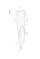
- FIG. Fig. 3 is an enlarged view of the vicinity of the tip of the puncture needle; 3 is a cross-sectional view taken along line III-III of FIG. 2;
- FIG. 10 is an enlarged view of the vicinity of the tip of the puncture needle of Modification 1;
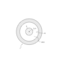
- FIG. 5 is a cross-sectional view taken along line VV of FIG. 4;
- FIG. 11 is an enlarged view of the vicinity of the tip of the puncture needle of Modification 2;
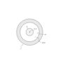
- FIG. 7 is a cross-sectional view taken along line VII-VII of FIG. 6;
- FIG. 1 shows a cautery needle device 200 having a puncture needle 100 and a laser fiber 9 according to this embodiment.
- the puncture needle 100 includes a cylindrical body portion 1 having a lumen S and a needle tip portion 2 formed at the distal end portion of the body portion 1 .
- the needle tip portion 2 closes the tip of the lumen S, and the needle tip T of the needle tip portion 2 overlaps with the axis G of the main body portion 1 .
- the laser fiber 9 is a member that forms an optical path, such as an optical fiber that can irradiate a laser serving as a heat source from its tip.
- a laser light source (not shown) for irradiating a laser beam to the optical path of the laser fiber 9 is connected to the proximal end of the laser fiber 9 .
- the puncture needle 100 is heated at the base end side of the needle tip portion 2 inside the lumen S by the laser light supplied from the laser fiber 9 . Then, the heat supplied to the needle tip portion 2 can heat or cauterize the affected area.
- the cauterization needle device 200 using the puncture needle 100 can accurately puncture the affected area with the puncture needle 100 as described later.
- the tip of the needle tip portion 2 can be appropriately heated according to the purpose of treatment of the affected area.
- the puncture needle 100 can be suitably used as an ovary puncture needle, for example.
- the cautery needle device 200 can be suitably used as a follicle growth induction device.
- the uses of the puncture needle 100 and the cautery needle device 200 are not limited to these.
- the main body 1 is, for example, cylindrical.
- a space defined by an inner wall 10 inside the cylinder of the main body 1 is a lumen S.
- FIG. 1 A space defined by an inner wall 10 inside the cylinder of the main body 1 is a lumen S.
- the main body 1 is preferably made of a material with high thermal conductivity, such as metal such as stainless steel, titanium, titanium alloy, cobalt-chromium alloy, or metal alloy.
- the main body 1 is made of stainless steel.
- the needle tip portion 2 is formed at the tip of the body portion 1 as described above, and has, for example, a conical shape.
- An example of the pyramidal shape is a conical shape or a polypyramidal shape including a plurality of plane portions on the side surface.
- Examples of the polygonal pyramid shape are a triangular pyramid shape, a square pyramid shape, and a pyramid shape with five or more angles.
- FIGS. 1 and 2 illustrate an example in which the needle tip portion 2 has a triangular pyramid shape. Note that FIG. 2 shows an enlarged view of the vicinity of the needle tip portion 2 of the puncture needle 100 .
- the needle tip T of the needle tip portion 2 overlaps with the axis G of the main body portion 1, as shown in FIGS.
- the puncture needle 100 can puncture the affected area accurately regardless of the position of the needle tip portion 2 in the circumferential direction around the axis G. That is, if the needle tip T does not overlap the axis G of the puncture needle 100, the point of puncture will deviate from the axis G of the puncture needle 100 during puncture using the puncture needle 100. Since the needle tip T is located at a position overlapping the axis G, the affected part can be punctured accurately.
- the lumen S is a space continuously formed along the axis G inside the main body 1 .
- the lumen S is formed as a columnar space whose axis overlaps with the axis G and whose cross section perpendicular to the axis G has a circular shape.
- the needle tip portion 2 closes the tip of the lumen S.
- a part of the inner wall 10 of the main body 1 which is located inside the needle tip 2 and closes the lumen S, is referred to as a closing portion 29 . That is, the body portion 1 is formed in a bottomed tubular shape in which the inner wall 10 on the distal end side of the lumen S is closed by the closing portion 29 serving as the tubular bottom.
- the lumen S is formed in the body portion 1 to reach the inside of the needle tip portion 2 . That is, the distal end of the lumen S is arranged inside the needle tip portion 2 in the direction along the axis G. As shown in FIG. As a result, the needle tip portion 2 can be heated from the inside, and the efficiency of supplying heat to the affected area is improved. For example, since the amount of heat that escapes due to heat transfer to the body portion 1 can be reduced, the temperature of the probe tip portion 2 can be quickly raised to a desired temperature. If the efficiency of heat supply to the affected area is improved, minimally invasive procedures can be realized, such as quick hemostasis at the affected area, or instantaneous cauterization of only the affected area while reducing damage to other areas.
- the tip of the lumen S should be overlapped with the axis G.
- the tip Ts of the lumen S is overlapped with the axis G. This makes it easier for the laser fiber 9 to be arranged at a position overlapping the axis G.
- the needle tip portion 2 is evenly inserted into the laser fiber. 9 can be heated.
- the lumen S should preferably have a shape that tapers toward the tip side. As a result, when the laser fiber 9 is pushed to the tip of the lumen S, the laser fiber 9 is naturally positioned at a position overlapping the axis G. As shown in FIG.
- the shape of the lumen S that tapers toward the distal end side (hereinafter, may be referred to as the “tip constricted shape of the lumen S”) is defined as The tip of S, ie, the closing portion 29, is illustrated as having a conical shape.
- the tip of S ie, the closing portion 29, is illustrated as having a conical shape.
- a lumen S is formed extending from the body portion 1 to the inside of the needle tip portion 2, and the tip Ts of the lumen S overlaps with the axis G. Therefore, the laser fiber 9 can heat the needle tip portion 2 directly behind the needle tip portion 2 .
- the cauterization needle device 200 using the puncture needle 100 requires an appropriate temperature rise up to the needle tip T according to the purpose of treatment of the affected area. If the temperature of puncture needle 100 is not properly increased to needle tip T, it may become difficult to form a solidified layer around needle tip portion 2 . Therefore, the risk of bleeding easily increases in some cases. In the cautery needle device 200, if the lumen S into which the laser fiber 9 is inserted is not formed close to the needle tip T, thermal conductivity tends to deteriorate, and the temperature of the needle tip T may not rise sufficiently.
- the needle tip portion 2 since the lumen S is formed from the body portion 1 to the inside of the needle tip portion 2 and the tip Ts of the lumen S overlaps with the axis G, the needle tip portion 2 In particular, since the laser can be irradiated directly behind the needle tip T, the temperature of the needle tip T can be raised appropriately.
- FIG. 3 is a cross-sectional view taken along line III-III in FIG.
- the tip concavity shape of the lumen S can take shapes other than a conical shape.
- the concavity shape at the tip of the lumen S may be changed to a conical shape, and may be a polygonal pyramid shape, a hemispherical shape, or a similar shape.
- Modification 1 4 and 5 show, as the shape of the tip of the lumen S, the needle tip of the puncture needle 100 when the tip portion of the lumen S, that is, the closing portion 29 has a triangular pyramid shape (an example of a polygonal pyramid shape). The figure which expanded the vicinity of the part 2 is shown. 5 is a cross-sectional view taken along line VV in FIG.
- Modification 2 6 and 7 show, as the shape of the tip of the lumen S, a puncture needle in which the tip portion of the lumen S, that is, the closing portion 29 has an elliptical hemispherical shape (an example of a hemispherical shape or similar shape).
- the figure which expanded the vicinity of the needle tip part 2 in 100 is shown.
- 7 is a cross-sectional view taken along line VII--VII in FIG.
- Other examples of hemispherical or similar shapes include oblong hemispherical shapes and shapes with cross-sections that are parabolic or hyperbolic.
- the main body 1 is made of a metal such as stainless steel or a metal alloy. Formation is not excluded. bottom.
- the lumen S is formed as a cylindrical space, but the lumen S can also be elliptical or prismatic.
- the puncture needle 100 has one lumen S, but the puncture needle 100 may have a lumen other than the lumen S. There may be.
- the cauterization needle device 200 includes the puncture needle 100 and the laser fiber 9.
- the cauterization needle device 200 may be a rod-shaped or cylindrical A member may further be provided.
- the present disclosure is applicable to puncture needles and cautery needle devices.
Landscapes
- Health & Medical Sciences (AREA)
- Surgery (AREA)
- Physics & Mathematics (AREA)
- Life Sciences & Earth Sciences (AREA)
- Engineering & Computer Science (AREA)
- Medical Informatics (AREA)
- Nuclear Medicine, Radiotherapy & Molecular Imaging (AREA)
- Electromagnetism (AREA)
- Optics & Photonics (AREA)
- Biomedical Technology (AREA)
- Heart & Thoracic Surgery (AREA)
- Otolaryngology (AREA)
- Molecular Biology (AREA)
- Animal Behavior & Ethology (AREA)
- General Health & Medical Sciences (AREA)
- Public Health (AREA)
- Veterinary Medicine (AREA)
- Surgical Instruments (AREA)
Priority Applications (1)
| Application Number | Priority Date | Filing Date | Title |
|---|---|---|---|
| JP2023574078A JPWO2023136305A1 (https=) | 2022-01-13 | 2023-01-12 |
Applications Claiming Priority (2)
| Application Number | Priority Date | Filing Date | Title |
|---|---|---|---|
| JP2022003839 | 2022-01-13 | ||
| JP2022-003839 | 2022-01-13 |
Publications (1)
| Publication Number | Publication Date |
|---|---|
| WO2023136305A1 true WO2023136305A1 (ja) | 2023-07-20 |
Family
ID=87279208
Family Applications (1)
| Application Number | Title | Priority Date | Filing Date |
|---|---|---|---|
| PCT/JP2023/000660 Ceased WO2023136305A1 (ja) | 2022-01-13 | 2023-01-12 | 穿刺針及び焼灼針装置 |
Country Status (2)
| Country | Link |
|---|---|
| JP (1) | JPWO2023136305A1 (https=) |
| WO (1) | WO2023136305A1 (https=) |
Citations (4)
| Publication number | Priority date | Publication date | Assignee | Title |
|---|---|---|---|---|
| JPH0488958U (https=) * | 1991-03-20 | 1992-08-03 | ||
| JP2001037775A (ja) * | 1999-07-26 | 2001-02-13 | Olympus Optical Co Ltd | 治療装置 |
| JP2017080440A (ja) * | 2013-01-09 | 2017-05-18 | 富士フイルム株式会社 | 光音響画像生成装置及び挿入物 |
| US20190159832A1 (en) * | 2017-11-28 | 2019-05-30 | Hangzhou Nuo Cheng Medical Instrument Co., Ltd | Treatment method for hypertrophic cardiomyopathy |
-
2023
- 2023-01-12 WO PCT/JP2023/000660 patent/WO2023136305A1/ja not_active Ceased
- 2023-01-12 JP JP2023574078A patent/JPWO2023136305A1/ja active Pending
Patent Citations (4)
| Publication number | Priority date | Publication date | Assignee | Title |
|---|---|---|---|---|
| JPH0488958U (https=) * | 1991-03-20 | 1992-08-03 | ||
| JP2001037775A (ja) * | 1999-07-26 | 2001-02-13 | Olympus Optical Co Ltd | 治療装置 |
| JP2017080440A (ja) * | 2013-01-09 | 2017-05-18 | 富士フイルム株式会社 | 光音響画像生成装置及び挿入物 |
| US20190159832A1 (en) * | 2017-11-28 | 2019-05-30 | Hangzhou Nuo Cheng Medical Instrument Co., Ltd | Treatment method for hypertrophic cardiomyopathy |
Also Published As
| Publication number | Publication date |
|---|---|
| JPWO2023136305A1 (https=) | 2023-07-20 |
Similar Documents
| Publication | Publication Date | Title |
|---|---|---|
| US8222564B2 (en) | Methods of altering surgical fiber | |
| US9345532B2 (en) | Methods and devices for ablation of tissue | |
| US6395002B1 (en) | Electrosurgical instrument for ear surgery | |
| US9198719B2 (en) | Electrosurgical fibroid ablation system and method | |
| US6221069B1 (en) | Apparatus for medical treatment | |
| US20130090637A1 (en) | Catheter device and method for denervation | |
| JP7165009B2 (ja) | 焼灼穿刺針 | |
| JP6316427B2 (ja) | 安定化機構を備えるガイドカテーテル、及びガイドカテーテルを挿入する方法 | |
| US20220313339A1 (en) | Spinal percutanous puncture plasma scalpel head and operation method of spinal percutaneous puncture plasma scalpel head | |
| JPH06205789A (ja) | レーザー光による手術装置 | |
| EP1464296A1 (en) | Catheter for cryoablation with a cryotip having a spiral and a straight configuration | |
| WO2019235520A1 (ja) | 卵胞発育誘導装置 | |
| US20120271293A1 (en) | Method for targeted local heat ablation using nanoparticles | |
| WO2023136305A1 (ja) | 穿刺針及び焼灼針装置 | |
| KR102668073B1 (ko) | 내시경용 고주파 처치구 | |
| Gil et al. | Novel laser tissue-soldering technique for dural reconstruction | |
| KR102788699B1 (ko) | 연성 내시경 시술기구의 바이폴라 구조 | |
| JPS63238860A (ja) | 医療用レーザプローブ | |
| JP2001120568A (ja) | 鼻腔内治療用レーザプローブ | |
| US9820809B2 (en) | Electrosurgical instrument | |
| US11832873B2 (en) | Cannulas for radio frequency ablation | |
| US20250000570A1 (en) | Radiofrequency Cannula for Thermal Ablation | |
| KR101769712B1 (ko) | 무혈절제용 레이저수술장치 | |
| US20060259103A1 (en) | Tissue ablation using multi-point convergent RF beams | |
| CN216898994U (zh) | 一种热敏型微波消融针测试工具 |
Legal Events
| Date | Code | Title | Description |
|---|---|---|---|
| 121 | Ep: the epo has been informed by wipo that ep was designated in this application |
Ref document number: 23740313 Country of ref document: EP Kind code of ref document: A1 |
|
| WWE | Wipo information: entry into national phase |
Ref document number: 2023574078 Country of ref document: JP |
|
| NENP | Non-entry into the national phase |
Ref country code: DE |
|
| 122 | Ep: pct application non-entry in european phase |
Ref document number: 23740313 Country of ref document: EP Kind code of ref document: A1 |