WO2023136240A1 - 情報処理方法、情報処理装置、情報処理システム、情報処理プログラム、及び焼結鉱製造方法 - Google Patents
情報処理方法、情報処理装置、情報処理システム、情報処理プログラム、及び焼結鉱製造方法 Download PDFInfo
- Publication number
- WO2023136240A1 WO2023136240A1 PCT/JP2023/000332 JP2023000332W WO2023136240A1 WO 2023136240 A1 WO2023136240 A1 WO 2023136240A1 JP 2023000332 W JP2023000332 W JP 2023000332W WO 2023136240 A1 WO2023136240 A1 WO 2023136240A1
- Authority
- WO
- WIPO (PCT)
- Prior art keywords
- information processing
- particles
- contour
- particle
- raw material
- Prior art date
- Legal status (The legal status is an assumption and is not a legal conclusion. Google has not performed a legal analysis and makes no representation as to the accuracy of the status listed.)
- Ceased
Links
Images







Classifications
-
- C—CHEMISTRY; METALLURGY
- C22—METALLURGY; FERROUS OR NON-FERROUS ALLOYS; TREATMENT OF ALLOYS OR NON-FERROUS METALS
- C22B—PRODUCTION AND REFINING OF METALS; PRETREATMENT OF RAW MATERIALS
- C22B1/00—Preliminary treatment of ores or scrap
- C22B1/14—Agglomerating; Briquetting; Binding; Granulating
- C22B1/16—Sintering; Agglomerating
-
- G—PHYSICS
- G01—MEASURING; TESTING
- G01N—INVESTIGATING OR ANALYSING MATERIALS BY DETERMINING THEIR CHEMICAL OR PHYSICAL PROPERTIES
- G01N15/00—Investigating characteristics of particles; Investigating permeability, pore-volume or surface-area of porous materials
- G01N15/02—Investigating particle size or size distribution
- G01N15/0205—Investigating particle size or size distribution by optical means
-
- G—PHYSICS
- G01—MEASURING; TESTING
- G01N—INVESTIGATING OR ANALYSING MATERIALS BY DETERMINING THEIR CHEMICAL OR PHYSICAL PROPERTIES
- G01N15/00—Investigating characteristics of particles; Investigating permeability, pore-volume or surface-area of porous materials
- G01N15/02—Investigating particle size or size distribution
- G01N15/0205—Investigating particle size or size distribution by optical means
- G01N15/0227—Investigating particle size or size distribution by optical means using imaging; using holography
-
- G—PHYSICS
- G01—MEASURING; TESTING
- G01N—INVESTIGATING OR ANALYSING MATERIALS BY DETERMINING THEIR CHEMICAL OR PHYSICAL PROPERTIES
- G01N15/00—Investigating characteristics of particles; Investigating permeability, pore-volume or surface-area of porous materials
- G01N15/10—Investigating individual particles
- G01N15/14—Optical investigation techniques, e.g. flow cytometry
- G01N15/1429—Signal processing
-
- G—PHYSICS
- G06—COMPUTING OR CALCULATING; COUNTING
- G06T—IMAGE DATA PROCESSING OR GENERATION, IN GENERAL
- G06T7/00—Image analysis
- G06T7/10—Segmentation; Edge detection
- G06T7/12—Edge-based segmentation
-
- G—PHYSICS
- G06—COMPUTING OR CALCULATING; COUNTING
- G06T—IMAGE DATA PROCESSING OR GENERATION, IN GENERAL
- G06T7/00—Image analysis
- G06T7/10—Segmentation; Edge detection
- G06T7/149—Segmentation; Edge detection involving deformable models, e.g. active contour models
-
- G—PHYSICS
- G01—MEASURING; TESTING
- G01N—INVESTIGATING OR ANALYSING MATERIALS BY DETERMINING THEIR CHEMICAL OR PHYSICAL PROPERTIES
- G01N15/00—Investigating characteristics of particles; Investigating permeability, pore-volume or surface-area of porous materials
- G01N2015/0096—Investigating consistence of powders, dustability, dustiness
-
- G—PHYSICS
- G01—MEASURING; TESTING
- G01N—INVESTIGATING OR ANALYSING MATERIALS BY DETERMINING THEIR CHEMICAL OR PHYSICAL PROPERTIES
- G01N15/00—Investigating characteristics of particles; Investigating permeability, pore-volume or surface-area of porous materials
- G01N15/02—Investigating particle size or size distribution
- G01N2015/0294—Particle shape
-
- G—PHYSICS
- G01—MEASURING; TESTING
- G01N—INVESTIGATING OR ANALYSING MATERIALS BY DETERMINING THEIR CHEMICAL OR PHYSICAL PROPERTIES
- G01N15/00—Investigating characteristics of particles; Investigating permeability, pore-volume or surface-area of porous materials
- G01N15/10—Investigating individual particles
- G01N15/14—Optical investigation techniques, e.g. flow cytometry
- G01N2015/1497—Particle shape
-
- G—PHYSICS
- G06—COMPUTING OR CALCULATING; COUNTING
- G06T—IMAGE DATA PROCESSING OR GENERATION, IN GENERAL
- G06T2207/00—Indexing scheme for image analysis or image enhancement
- G06T2207/10—Image acquisition modality
- G06T2207/10028—Range image; Depth image; 3D point clouds
-
- G—PHYSICS
- G06—COMPUTING OR CALCULATING; COUNTING
- G06T—IMAGE DATA PROCESSING OR GENERATION, IN GENERAL
- G06T2207/00—Indexing scheme for image analysis or image enhancement
- G06T2207/20—Special algorithmic details
- G06T2207/20112—Image segmentation details
- G06T2207/20116—Active contour; Active surface; Snakes
Definitions
- the present disclosure relates to an information processing method, an information processing device, an information processing system, an information processing program, and a sintered ore manufacturing method.
- a device that can measure the particle size of each particle of a granular industrial raw material such as coke with high measurement accuracy (see Patent Document 1, for example).
- the production conditions are set according to the properties of the particles contained in the raw materials. In order to improve product quality, it is required to improve the measurement accuracy of particle properties.
- the present disclosure provides an information processing method, an information processing device, an information processing system, an information processing program, and a sintered ore production method based on the measurement results of the properties of particles that can improve the measurement accuracy of the properties of particles. aim.
- An information processing method includes a step of obtaining profile data of the raw material including distance data to the raw material including a plurality of particles or image data of the raw material; and detecting contours of at least some of the plurality of particles from the profile data based on the feature points.
- An information processing apparatus includes a control unit that executes the information processing method.
- An information processing system includes the information processing device and a measuring device that outputs profile data of the raw material to the information processing device.
- An information processing program causes a processor to execute the information processing method.
- a sintered ore production method includes a step of measuring the properties of particles contained in a raw material by executing the information processing method, and based on the measurement results of the properties of the particles, the and setting conditions for producing sintered ore using raw materials.
- the measurement accuracy of the properties of the particles can be improved. Moreover, the measurement results of the properties of the particles can be reflected in the sintered ore production method.
- FIG. 1 is a schematic diagram showing a configuration example of an information processing system according to the present disclosure
- FIG. 1 is a block diagram showing a configuration example of an information processing system according to the present disclosure
- FIG. 4 is a flow chart showing an example procedure of an information processing method according to the present disclosure
- FIG. 4 is a cross-sectional view showing an example of profile data
- FIG. 4 is a diagram showing an example of feature points detected in profile data
- FIG. 10 is a diagram showing an example of detecting the contour of a particle in a direction spreading from a feature point
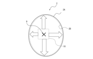
- FIG. 10 is a diagram showing an example of detecting the contour of a particle by expanding an initial contour set based on feature points
- FIG. 10 is a diagram showing a comparative example in which the contour of a particle is detected by narrowing the initial contour set outside the particle;
- FIG. 10 is a diagram showing an initial contour set outside the profile data as a comparative example;
- Figure 9B shows the contours of particles detected by narrowing the initial contours in Figure 9A;
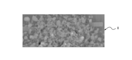
- It is a figure showing an example of profile data as an image.
- 10B is a diagram showing particles identified by detecting contours from the profile data of FIG. 10A by a method according to a comparative example;
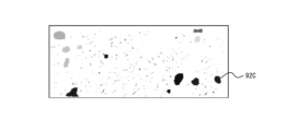
- FIG. 10B is a diagram showing particles identified by detecting contours from the profile data of FIG. 10A by the information processing method according to the present disclosure;
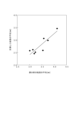
- FIG. 4 is a graph showing an example of the correlation between particle size in sieve analysis and particle size in measurement.
- FIG. 9 is a flowchart showing another procedure example of the information processing method. It is a schematic diagram which shows the structural example which combined the raw material charging apparatus and the sintering furnace.
- FIG. 3 is a schematic diagram showing another configuration example in which a raw material charging device and a sintering furnace are combined;
- the particle size or shape of the raw material, or the particle size distribution affects the operation of the manufacturing process. Therefore, it is required to measure and understand the properties of raw materials in advance.
- Particle size affects airflow in the sintering machine. Therefore, it is important to grasp the particle size or particle size distribution of the particles that are the raw material of the granulated particles.
- the particle size distribution of raw materials can be analyzed by sampling and sieving the raw materials.
- the analysis using the sieve takes time, it is difficult to reflect the analysis results in the blast furnace operation in real time. Therefore, a technique for measuring the particle size distribution of raw materials in real time is required.
- the particle size distribution of the raw material can be measured in real time by acquiring measurement data such as an image or shape of the top of the raw material using a camera or laser rangefinder.
- Particles can be individually detected by detecting the contours of the particles contained in the raw material and recognizing the areas within the contours as individual particle regions.
- Object contours can generally be detected based on changes in spatial height data.
- the edges which are the outlines of raw materials, are detected by detecting spatially concave positions based on 3D shape data of rocks deposited on a conveyor acquired using a laser rangefinder.
- Reference 1 Matthew J. Thurley, Automated Online Measurement of Particle Size Distribution using 3D Range Data, IFAC Proceedings Volumes, 2009, 42, 134-139
- the smaller the particles of the raw material to be measured the less clear the outline of each particle, and the smaller the change in height of the raw material as a whole.
- the smaller the particles of the raw material the lower the detection accuracy of the contours of the particles.
- the calculation load may increase due to calculating the height of each point of each rock. Therefore, it is difficult to measure the particle size in real time.
- the detection accuracy of the contours of particles contained in raw materials can be improved.
- particle contours can be robustly detected.
- the measurement accuracy of particle properties can be improved.
- the contours of particles such as coke, ore, or sinter, which are raw materials deposited and conveyed on a conveyor, can be detected with high accuracy.
- the contours of particles such as fine ore, limestone, granulated particles, or coal that are smaller than sintered ore and the like, which are used to manufacture sintered ore and the like, can be detected with high accuracy.
- an information processing system 100 includes an information processing device 4 and a measurement device 3 .
- the measuring device 3 acquires information about the particles 2 deposited on the conveyor 1 and transported.
- the information processing device 4 detects the contour of the particle 2 based on the information regarding the particle 2 .
- the information processing device 4 also measures the properties of the particles 2 based on the detection results of the contours of the particles 2 .
- the conveyor 1 is a conveyor that conveys granulated particles used in sintering machines in the steel industry, but is not limited to this.
- the particles 2 are granulated particles that are one of the raw materials used in the steel industry, but are not limited to this.
- Particles 2 may include, for example, coke, ore, sinter, pellets, limestone, rock, coal, ore fines, coke fines, or the like.
- the information processing device 4 includes a control section 40 , a communication section 48 , an output section 46 and an input section 47 .
- the control unit 40 may include at least one processor such as a CPU (Central Processing Unit) or a GPU (Graphics Processing Unit) in order to control and manage various functions of the information processing device 4 .
- the control unit 40 may be composed of one processor, or may be composed of a plurality of processors.
- the processor constituting the control unit 40 may implement the functions of the information processing device 4 by reading and executing a program stored in a storage unit, which will be described later.
- the control unit 40 may be subdivided into constituent units that implement various functions of the information processing device 4 .
- the control unit 40 is assumed to include a measurement unit 41 , a detection unit 42 and a calculation unit 43 . The operation of each component of the control unit 40 will be described later.
- the control unit 40 may include a storage unit.
- the storage unit stores various information or data.
- the storage unit may store, for example, programs executed by the control unit 40, data used in processing executed by the control unit 40, results of processing, or the like.
- the storage section may function as a work memory for the control section 40 .
- the storage unit may include, for example, a semiconductor memory or the like, but is not limited to this.
- the storage unit may be configured as an internal memory of a processor used as the control unit 40 or configured as a hard disk drive (HDD) accessible from the control unit 40 .
- the storage unit may be configured as a non-transitory readable medium.
- the storage unit may be configured integrally with the control unit 40 or may be configured separately from the control unit 40 .
- the communication unit 48 may include a communication interface for communicating with other devices such as the measuring device 3 by wire or wirelessly.
- the communication interface may be configured to communicate with other devices over a network.
- the communication unit 48 may be configured including an input/output port for inputting/outputting data with another device.
- the communication unit 48 transmits and receives necessary data and signals to and from the process computer or host system.
- the communication unit 48 may communicate based on a wired communication standard, or may communicate based on a wireless communication standard.
- wireless communication standards may include cellular phone communication standards such as 3G, 4G and 5G.
- wireless communication standards may include IEEE 802.11, Bluetooth (registered trademark), and the like.
- Communication unit 48 may support one or more of these communication standards.
- the communication unit 48 is not limited to these examples, and may communicate with other devices and input/output data based on various standards.
- the output unit 46 outputs information acquired from the control unit 40 .
- the output unit 46 may notify the user of information by outputting visual information such as characters, graphics, or images directly or via an external device or the like.
- the output unit 46 may include a display device, or may be connected to the display device by wire or wirelessly.
- the display device may include various displays such as, for example, liquid crystal displays.
- the output unit 46 may notify the user of information by outputting auditory information such as voice directly or via an external device or the like.
- the output unit 46 may include an audio output device such as a speaker, or may be connected to the audio output device by wire or wirelessly.
- the output section 46 may comprise a vibration device.
- the output unit 46 may notify the user of information by outputting not only visual information, auditory information, or tactile information, but also information that the user can perceive with other senses, either directly or via an external device.
- the input unit 47 may include an input device that receives input from the user.
- the input device may include, for example, a keyboard or physical keys, or may include a touch panel or touch sensor, or a pointing device such as a mouse.
- Input devices are not limited to these examples, and may include other various devices.
- the measuring device 3 is assumed to be a laser rangefinder.
- the laser rangefinder irradiates a laser beam linearly along the width direction of the conveyor 1 (the depth direction of the paper surface in FIG. 1), and measures the distance to the particle 2, which is the object to be measured, for each line. Particles 2 move in the conveying direction by being deposited on conveyor 1 and conveyed.
- the laser rangefinder can generate three-dimensional shape data of the particle 2 by linearly measuring the distance to the particle 2 at a constant measurement cycle and integrating the measured distance values in each line.
- the method described above is a method of obtaining the three-dimensional shape of the object to be measured by the so-called light section method.
- a laser rangefinder and data processing means used to implement the light section method may be employed.
- the measurement area of the laser rangefinder may be set to the same area as the width of the conveyor 1, or may be set to an area larger than the width of the conveyor 1.
- the laser range finder may be configured to measure the entire particle 2 conveyed by the conveyor 1 .
- the measurement density of the three-dimensional shape data is increased.
- the measurement frequency is set to 4 kHz (in this case, the measurement period is 0.25 milliseconds).
- the measuring device 3 is not limited to a laser rangefinder, and may be configured by a distance measuring camera using a TOF (Time Of Flight) method.
- the measuring device 3 generates three-dimensional shape data of the particles 2 deposited on the conveyor 1 or distance data from the measuring device 3 to the particles 2 and outputs the data to the information processing device 4 .
- the measuring device 3 may be configured including an imaging device such as a camera, for example.
- the measuring device 3 captures an image of the deposited material including the plurality of particles 2 deposited on the conveyor 1 and outputs the captured image to the information processing device 4 .
- the measuring device 3 generates image data of the particles 2 deposited on the conveyor 1 and outputs the image data to the information processing device 4 .
- the measuring device 3 may generate distance data from the measuring device 3 to the particles 2 using the image data, and output the distance data to the information processing device 4 .
- the measuring device 3 may be configured as a stereo camera that generates distance data from correlation correspondence between two images using a stereo method using two cameras.
- the measuring device 3 calculates the image data based on the correlation between the brightness of the image of the particle 2 and the distance to the particle 2 (for example, the higher the brightness, the closer the point is to the measuring device 3). You may convert into distance data.
- the control unit 40 of the information processing device 4 acquires the three-dimensional shape data, distance data, or image data of the particles 2 deposited on the conveyor 1 from the measurement device 3 through the communication unit 48 .
- Three-dimensional shape data, distance data, or image data are also collectively referred to as profile data.
- the controller 40 detects contours of the particles 2 deposited on the conveyor 1 based on profile data acquired from the measuring device 3 .
- the control unit 40 may measure the properties of the particles 2 based on the detection results of the contours of the particles 2 .
- the profile data of the particles 2 being transported as sediments on the conveyor 1 are represented as one profile data in which individual particles 2 cannot be distinguished.
- the control unit 40 needs to distinguish and detect each particle 2 .
- the control unit 40 can distinguish individual particles 2 by detecting the outlines of at least some of the particles 2 and recognizing the areas surrounded by the outlines as the particles 2 .
- the profile data is three-dimensional shape data or distance data
- the smaller the particle 2 the smaller the change in height of the particle 2 may be.
- the profile data is image data, the smaller the change in height of the particles 2, the smaller the difference in brightness. As a result, it becomes difficult to detect the outline of the particle 2 from the profile data.
- the control unit 40 of the information processing device 4 detects the feature points of the particle 2 from the profile data, and detects the contour of the particle 2 based on the feature points of the particle 2.
- An operation example in which the controller 40 detects the contour of the particle 2 based on the profile data of the particle 2 will be described below based on the procedure of the flowchart illustrated in FIG.
- the control unit 40 can detect the contour of the particle 2 by executing the information processing method including the procedure of the flowchart illustrated in FIG.
- the information processing method may be implemented as an information processing program to be executed by a processor configuring the control unit 40 .
- the information processing program may be stored in a non-transitory computer-readable medium.
- the control unit 40 acquires profile data of the particle 2 (step S1). Specifically, the control unit 40 may generate the profile data of the particles 2 by processing the measurement data of the measurement device 3 in the measurement unit 41, or acquire the profile data of the particles 2 from the measurement device 3. good too. The control unit 40 may implement the function of acquiring or measuring profile data of the particles 2 as the measurement unit 41 .
- the control unit 40 detects feature points of the particle 2 from the profile data (step S2).
- the control unit 40 may implement the function of detecting the feature points of the particles 2 as the detection unit 42 .
- the control unit 40 may detect the vertex of the particle 2 as the characteristic point of the particle 2 . Detecting vertices as feature points is based on the fact that the number of vertices detected in one particle 2 is approximately one.
- the control unit 40 may detect the maximum value of the height of the particle 2 as the vertex of the particle 2 when the profile data is the height data of the particle 2 . If the profile data is image data of the particle 2, the control unit 40 may detect the apex of the particle 2 by image processing.
- control unit 40 may acquire distance data representing the relationship between the height of the particle 2 and the position in the width direction of the conveyor 1 as profile data, as illustrated in FIG.
- the feature points 9 are indicated by crosses as points corresponding to the vertices of the particles 2 .
- control unit 40 may acquire an image representing the distance data of the particle 2 as profile data, as illustrated in FIG.
- the feature point 9 is represented by a white point as a point corresponding to the vertex of the particle 2 (the point at which the height reaches the maximum value). The point at which the height reaches the maximum value is located approximately at the center of the particle 2 . Also, it can be confirmed that the number of characteristic points 9 roughly corresponds to the number of particles 2 that can be visually determined.
- the control unit 40 may detect feature points of the particle 2 by image processing. For example, the control unit 40 may detect the feature points of the particles 2 from the image data based on a model that has been learned by machine learning or the like. The control unit 40 may detect feature points of the particles 2 from the image data based on a predetermined algorithm such as pattern matching.
- the control unit 40 detects the contour of the particle 2 based on the feature points of the particle 2 (step S3).
- the control unit 40 may implement the function of detecting the contour of the particle 2 as the detection unit 42 .
- the control unit 40 may detect the contour of the particle 2 in a direction extending from the feature point 9 detected in the profile data of the particle 2 to the surroundings.
- the true contour 2A of the particle 2 is indicated by solid lines.
- the detected contour 2B is indicated by a dashed line.
- the control unit 40 calculates the change in height along the direction spreading from the feature point 9 to the surroundings.
- the control unit 40 may detect the point at which the amount of change in height is equal to or greater than the height change threshold as the contour 2B of the particle 2 .
- the height change threshold can be set as appropriate.
- the control unit 40 may detect the contour of the particle 2 by calculating changes in height in each of a plurality of directions extending from the feature point 9 to the surroundings.
- the control unit 40 calculates the change in luminance along the direction spreading from the feature point 9 to the surroundings.
- the control unit 40 may detect a point at which the amount of change in brightness is greater than or equal to the brightness change threshold as the contour 2B of the particle 2 .
- the brightness change threshold can be set as appropriate.
- the control unit 40 may detect the contour of the particle 2 by calculating changes in luminance in each of a plurality of directions extending from the feature point 9 to the surroundings.
- the control unit 40 may detect the contour of the particle 2 by setting the initial contour 10 based on the feature points 9 and spreading the initial contour 10 around, as shown in FIG.
- the control unit 40 may set a rectangular closed curve such as a square surrounding the feature point 9 as the initial contour 10 .
- the initial contour 10 is not limited to a rectangle, and may be other polygons, or various curves such as a circle or an ellipse.
- the control unit 40 may set the size of the initial contour 10 so that the initial contour 10 fits within the area of the particle 2 .
- the control unit 40 may set the size or shape of the initial contour 10 based on human input.
- the size or shape of the initial contour 10 can be set based on the size of the particle 2 whose contour is to be detected, the pixel size of the profile data, or the resolution of the measuring device 3 that measures the profile data.
- the control unit 40 may use an active contour model to detect the contour of the particle 2 based on the initial contour 10.
- the active contour model can be understood by referring to the reference (Ryo Kurazume: Level set method and its implementation method, JP-A-2015-114172).
- an evaluation function is set that accepts an arbitrary curve as an input and outputs an evaluation value of the input curve.
- the evaluation function is set so that the closer the input curve is to the contour of the particle 2, the smaller the evaluation value is output.
- the evaluation function is set to output the minimum value as the evaluation value when the input curve matches the contour of the particle 2 .
- the evaluation function is evaluated based on, for example, the variance of the data inside and outside the area surrounded by the input curve, the length of the input curve, or the area of the area surrounded by the input curve. can output a value.
- the control unit 40 estimates a curve corresponding to the contour of the particle 2 so that the evaluation value output from the evaluation function is small. Based on the change in the evaluation value when the curve corresponding to the contour of the particle 2 is changed, the control unit 40 repeatedly changes the curve so that the evaluation value approaches the minimum value. That is, the control unit 40 estimates a curve corresponding to the contour of the particle 2 so as to minimize the evaluation value, and detects the estimated curve as the contour of the particle 2 .
- the curve estimated to minimize the evaluation value is represented by a dashed line as contour 2B detected by estimating the true contour 2A from the inside.
- CHAN et al. proposed a method called the level set method (T. F. Chan and L. A.
- the contour detection method is not limited to this, and may be various other methods such as the SNAKE method, which is a kind of active contour model.
- the control unit 40 needs to set the initial contour 10 at a position close to the true contour 2A by some method.
- the initial contour 10 can be set based on the content input by a human through the input unit 47 .
- an initial contour 90 represented by a dashed line is set to the outer edge of the profile data for particle 92, as shown in FIG. Particle 92 has a true contour 92A represented by a solid line. If the particle 92 were present alone, the detected contour 92B, represented by the dash-dotted line, would approximate the true contour 92A.
- control unit 40 can set the initial contour based on feature points located inside the particle 2 .
- the detection accuracy of the contours of individual particles can be increased as compared to simply setting the initial contours to the outer edges of the profile data.
- FIG. 10B shows the result of detecting the contour from the profile data of FIG. 10A by differentiating the profile data as another method according to the comparative example.
- FIG. 10C shows the result of contour detection from the profile data of FIG.
- FIG. 10C the area enclosed by the detected contour is indicated as detected particle area 2C.
- FIG. 10C small particle areas are detected that are not detected in FIG. 10B. That is, according to the information processing method according to the present embodiment, it can be said that the outline of the particle 2 is detected with high accuracy regardless of the size of the particle 2 .
- the control unit 40 may use the output unit 46 to display or output the detection result of the contour of the particle 2, or may use the communication unit 48 to output the detection result of the contour of the particle 2 to another device. After executing the procedure of step S3 of FIG. 3, the control unit 40 ends the execution of the procedure of the flowchart of FIG.
- the control unit 40 may measure the properties of the particles 2 based on the results of detecting the contours of the particles 2 from the profile data.
- the control unit 40 may implement the function of measuring the properties of the particles 2 as the calculation unit 43 .
- the control unit 40 may measure, for example, the particle size, shape, aspect ratio in plan view, surface roughness, etc. of the particles 2 as properties of the particles 2 .
- An example in which the control unit 40 measures the particle size of the particles 2 as the properties of the particles 2 will be described below.
- the control unit 40 may measure the particle size of the particles 2 by, for example, a circular approximation fitting method.
- the circular approximation fitting method is a method of approximating the area determined to be the particle 2 with a perfect circle having an area equal to the area of the area determined to be the particle 2 and calculating the diameter of the approximated circle as the particle size of the particle 2.
- the control unit 40 may measure the particle size of the particles 2 by various other methods without being limited to the circular approximation fitting method.
- the control unit 40 may display or output the measurement results of the properties of the particles 2 through the output unit 46 , and may output the measurement results of the properties of the particles 2 to another device through the communication unit 48 .
- the particle size of the particles 2 in this embodiment is a value measured from the profile data of the deposit material in which a certain group of a plurality of particles 2 are deposited.
- the particle size measured by sieve analysis is obtained by collectively measuring the particle size of each of the plurality of particles 2 in the same group as the deposited substance for which the particle size of the particle 2 in this embodiment is measured by sieve analysis. is a value calculated by taking the average value of the particle diameters of , as the particle diameter of the particles 2 in the one group.
- a deposition material on which particles 2 are deposited is prepared, and the particle size of each particle 2 is measured from the profile data.
- the particle size of the particles 2 contained in the deposited material was measured by sieve analysis.
- the horizontal axis represents the average particle size measured by sieve analysis.
- the vertical axis represents the average value of particle diameters measured by the information processing method according to the present embodiment.
- the correlation coefficient (R ⁇ 2) between the measurement result by the sieve analysis and the measurement result by the information processing method according to this embodiment was calculated to be 0.80. It is believed that the sieve analysis particle size is close to the actual particle size. Therefore, it can be said that the measurement result obtained by the information processing method according to the present embodiment is close to the actual particle size. That is, it can be said that the measurement accuracy of the particle size of the particles 2 by the information processing method according to the present embodiment is high.
- the contour of the particle 2 can be determined with high accuracy based on the feature points. can be detected at Moreover, the particle size of the particle 2 can be measured with high accuracy based on the detected contour.
- the particle size of the particles 2 was measured as the properties of the particles 2 .
- Various other items may be measured as properties of the particles 2 .
- the property of the particle 2 the surface shape (surface roughness) may be measured.
- the information processing device 4 is also called a property measuring device that measures properties of the particles 2 .
- the initial contour of the active contour model can be automatically set with high accuracy.
- the contour of the particle 2 can be detected and the properties can be measured in real time.
- the information processing apparatus 4 and the information processing method according to the present embodiment can be used, for example, in a manufacturing process such as a blast furnace to determine the properties of coke, ore, or sintered ore, which are raw materials deposited and conveyed on a conveyor. Applicable to measurement.
- the information processing device 4 and the information processing method according to the present embodiment can be used to determine the properties of fine ore, limestone, granulated particles, coal, or the like, which are raw materials having a smaller particle size than coke, ore, or sintered ore. It can also be applied to measurement.
- Particle 2 profile data may contain noise.
- the control unit 40 of the information processing device 4 may perform smoothing processing for reducing noise as preprocessing for detecting feature points from the profile data. Smoothing may be achieved by reducing high frequency components of the spatial frequencies of the profile data, for example by a low pass filter or a band pass filter. It can be said that the wider the range of frequencies to be reduced (the lower the cutoff frequency on the high frequency side), the higher the degree of smoothing processing.
- a smoothing process can also be achieved by averaging the pixels of the profile data with a filter of predetermined size. It can be said that the larger the filter size, the higher the degree of smoothing processing. It can be said that the degree of unevenness (surface roughness) of the profile data is reduced by executing a high degree of smoothing processing.
- Both noise reduction and detection of small-sized particles 2 can be achieved by a low degree of smoothing.
- a high degree of smoothing can reduce noise and increase detection accuracy of large size particles.
- the control unit 40 may detect the contours of the particles 2 with a large particle size and the contours of the particles 2 with a small particle size separately by smoothing the profile data at two degrees. That is, the controller 40 may detect the contour of the particle 2 in two stages. Specifically, as the first stage of processing, the control unit 40 executes a high degree of smoothing processing as the first smoothing processing to generate first smoothed data, and based on the first smoothed data feature points and contours of relatively large particles 2 may be detected.
- the feature points of the particles 2 detected based on the first smoothed data are also referred to as first feature points.
- the contour of the particle 2 detected based on the first smoothed data is also called the first contour.
- the control unit 40 performs a low degree smoothing process as a second smoothing process to generate second smoothed data, and based on the second smoothed data, a relatively small Feature points and contours of particles 2 may be detected.
- the feature points of the particles 2 detected based on the second smoothed data are also referred to as second feature points.
- the contours of particles 2 detected based on the second smoothed data are also referred to as second contours.
- the influence of noise is likely to be reduced in detecting the contour (first contour) of the large particle 2 .
- the outline (second outline) of the small particles 2 becomes easier to detect by lowering the degree of smoothing. That is, both the detection of the contours of large particles 2 (first contour) and the detection of the contours of small particles 2 (second contour) can be realized.
- the control unit 40 Prior to the second stage processing, the control unit 40 excludes from the profile data or masks with the profile data the area surrounded by the outline (first outline) of the large particle 2 detected in the first stage processing. You can That is, the control unit 40 may detect the second feature point or the second contour in an area of the profile data excluding the area surrounded by the first contour. In the process of the second stage, the control unit 40 detects only the contours of the small particles 2 without overlapping the contours of the already detected large particles 2 by considering the areas detected in the process of the first stage. can. The control unit 40 may delete overlapping outlines of the particles 2 detected in the processing of the first stage and the second stage.
- the control unit 40 may execute an information processing method including the procedure of the flowchart illustrated in FIG. 12 as the two-stage processing described above.
- the control unit 40 acquires profile data of the particle 2 (step S11).
- the control unit 40 may acquire the profile data of the particles 2 by operating in the same or similar manner as the procedure of step S1 in FIG.
- the control unit 40 executes the first smoothing of the profile data (step S12).
- the control unit 40 detects feature points (first feature points) from the first smoothed data (step S13).
- the control unit 40 sets an initial contour based on the feature points (first feature points) (step S14).
- the control unit 40 detects the first contour based on the initial contour in the active contour model (step S15).
- the control unit 40 identifies the area surrounded by the first outline in the profile data (step S16). Specifically, the control unit 40 may exclude the data of the area surrounded by the first outline from the profile data, or may set the area surrounded by the first outline as a mask on the profile data. .
- the control unit 40 executes the second smoothing of the profile data (step S17).
- the control unit 40 detects feature points (second feature points) from the second smoothed data (step S18).
- the control unit 40 sets an initial contour based on the feature points (second feature points) (step S19).
- the control unit 40 detects a second contour based on the initial contour in the active contour model (step S20).
- the control unit 40 confirms overlap between the first contour and the second contour (step S21). Specifically, when the area surrounded by the first outline and the area surrounded by the second outline overlap, the control unit 40 deletes the other areas while leaving only one of the overlapping areas.
- the contour detection results may be modified so that The control unit 40 measures the properties of each particle based on the detection result of the contour of each particle (step S22). After executing the procedure of step S22, the control unit 40 ends the execution of the procedure of the flowchart of FIG.
- the control unit 40 may detect a plurality of feature points in one particle 2. In this case, the particle regions enclosed by the contours detected based on each feature point may overlap. The control unit 40 may determine whether there is an overlapping particle region based on the detected contour, and correct the contour detection result based on the determination result. For example, the control unit 40 may leave only one of the overlapping contours and delete the detection results of the other contours. By doing so, multiple detection of one particle area by multiple vertices can be prevented. As a result, contour detection accuracy can be enhanced. Also, the larger the particles 2 of the raw material, the more complicated the shape of the particles 2 tends to be.
- the contour position may not converge depending on the object.
- the contour position converges, even if the number of iterative calculations for changing and searching the contour is set large, the contour remains at the position with the minimum evaluation value (energy), so there is no problem.
- the contour position does not converge, the result will be far from the contour position unless the number of iterations is set appropriately. Therefore, it is desirable to appropriately set the number of iterative calculations in advance.
- the contour extracted by the dynamic contour model captures a rough particle existence area.
- edge detection processing may be performed within the contour extracted by the active contour model in order to accurately capture the particle contour.
- the edge detection process may be configured as a single Canny filter process that is easy to detect even unclear edges, for example.
- Edge detection processing may be configured as a combination of Canny filter processing and dilation processing or erosion processing, for example. Even if one contour is not extracted by applying Canny filtering alone, it can be connected to one contour by applying dilation or erosion processing. By applying edge detection processing to a narrow range of individual particle existence areas, the contours of unclear individual particles that could not be captured by applying edge detection processing to the entire image or distance data where multiple particles are accumulated can be detailed. It may be captured.
- the control unit 40 detects the contour using edge detection processing in at least one of the region surrounded by the first contour and the region surrounded by the second contour. good too.
- the outline of the granulated particles that are the raw material of the sintered ore may be detected by the information processing device 4 and the information processing method described above. Also, the properties of the granulated particles may be measured. Generally, the size of granulated particles after granulation is desired to be large and to be uniform over time (when viewed). Moreover, it is desired that the individual particle diameters are uniform. However, due to variations in the properties of the raw material particles before granulation, or the effects of moisture brought in with the raw materials, etc., even though a certain amount of operation is maintained in the operation of the granulation process, granulated particle size may vary over time. Also, the particle size may be smaller than desired. As a result, when the granulated particles are charged into the sintering machine, the airflow tends to become unstable or deteriorate. Unstable or reduced aeration can reduce the quality of the sinter produced.
- the method of charging the granulated particles into the sintering machine after granulation is also important.
- An outline of the configuration of the raw material charging device is shown as FIG. 13 or FIG.
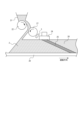
- the raw material charging device includes a surge hopper 21, a drum feeder 22, and a chute 23.
- the raw material charging device supplies particles 2, which are raw materials for producing sintered ore in a sintering furnace, to an endlessly movable pallet 20 and deposits them.
- surge hopper 21 feeds particles 2 into drum feeder 22 .
- Drum feeder 22 rotates clockwise and feeds particles 2 into chute 23 .
- the chute 23 is inclined at an angle represented by ⁇ with respect to the horizontal plane, and the particles 2 fed from the drum feeder 22 are slid on the surface to be fed onto the pallet 20 and deposited on the pallet 20 .
- the pallet 20 By conveying the particles 2 in the conveying direction (rightward in FIG. 13), the pallet 20 charges the deposited material on which the particles 2 are deposited into the sintering furnace.
- the sintering furnace is equipped with an ignition furnace 24.
- the ignition furnace 24 ignites the surface layer of the deposited material carried by the pallet 20 .
- Sedimentary materials include combustible materials such as coagulants or carbonaceous materials.
- the ignition furnace 24 ignites the combustible material on the surface layer of the deposited material.
- the ignited surface layer begins to burn.
- the portion that is burning is designated as burning portion 25 .
- the sintering furnace is further equipped with an exhaust fan that draws air from the top of the deposited material on the pallet 20 toward the bottom of the pallet 20. While the deposited material is being carried by the pallet 20, the air flow from the top to the bottom of the pallet 20 causes the combustion section 25 to move from the surface layer toward the bottom. The particles 2 are heated and melted by the combustion heat generated in the combustion section 25 . The particles 2 melted in the combustion section 25 combine with other particles 2 to become sintered ore 26 after the completion of combustion. As the transportation by the pallet 20 progresses, the layer of the portion changed from the particles 2 to the sinter 26 in the sediment material becomes thicker. All the particles 2 are changed into sintered ore 26 by the combustion part 25 reaching the lower part of the pallet 20 .
- the raw material charging device may have a drum chute 27 instead of the chute 23 of FIG.
- the drum feeder 22 rotates clockwise to feed the particles 2 into the drum chute 27 .
- the drum chute 27 rotates counterclockwise to throw the particles 2 onto the pallet 20 and deposit them on the pallet 20 .
- the particle size distribution in the height direction does not change with time.
- the height direction of the granulated particles after granulation deposited on the pallet 20 will be The distribution of particle size changes.
- the ventilation of the sintering machine tends to become unstable or deteriorate. Unstable or reduced aeration can reduce the quality of the sinter produced.
- the information processing device 4 and the information processing method according to the present embodiment it becomes easier to grasp the particle size of the granulated particles. In addition, it becomes possible to constantly grasp the particle size of the granulated particles.
- the raw material charging apparatus illustrated in FIG. 13 or 14 the properties of the particles 2 contained in the deposited material before being ignited in the ignition furnace 24 are measured by the measuring device 3 .
- the raw material charging device may feed back the measurement results of the properties of the particles 2 to the conditions for charging the particles 2 .
- the particle size in the manufacturing process using granulated particles, it is possible to control the particle size to the desired size by changing the operating factors that affect the particle size, thereby reducing variations in particle size. Furthermore, by adjusting the operating factors related to the method of charging the raw material into the sintering machine, it is possible to uniformly adjust the temporal change in the variation in the particle size of the raw material deposited on the pallet 20 of the sintering machine in the height direction. becomes possible. In other words, the conditions for producing sintered ore can be set based on the particle size of the granulated particles.
- particles after granulation Diameter can be controlled.
- the particle size after granulation can be controlled to a desired particle size by adjusting at least one of the rotation speed of the granulator, the residence time, and the added moisture as the sintered ore production conditions.
- the number of revolutions of the drum feeder 22 of the raw material charging device and the angle ( ⁇ ) of the chute 23 are increased, and after granulation
- the pallet 20 of the sintering machine It is possible to uniformly adjust the temporal variation of the grain size variation in the height direction of the raw material deposited thereon.
- the properties of the particles 2 contained in the deposited material are determined based on at least one of the rotation speed of the drum feeder 22 and the angle ( ⁇ ) of the chute 23. .
- at least one of the number of rotations of the drum feeder 22 of the raw material charging device or the angle ( ⁇ ) of the chute 23 may be adjusted.
- the properties of the particles 2 contained in the deposited material are determined based on at least one of the rotation speed of the drum feeder 22 and the rotation speed of the drum chute 27 .
- at least one of the rotation speed of the drum feeder 22 or the rotation speed of the drum chute 27 of the raw material charging device may be adjusted.
- At least one of the rotation speed of the drum feeder 22 of the raw material charging device, the angle ( ⁇ ) of the chute 23, or the rotation speed of the drum chute 27 is adjusted. may be any one of the rotation speed of the drum feeder 22 of the raw material charging device, the angle ( ⁇ ) of the chute 23, or the rotation speed of the drum chute 27 is adjusted.
- the rotation speed of the drum feeder 22 and the angle ( ⁇ ) of the chute 23 are changed.
- the charging conditions of the particles 2 by the raw material charging device may be set so as to increase.
- the charging conditions for the particles 2 by the raw material charging device may be set so as to decrease the rotational speed of the drum feeder 22 and the angle ( ⁇ ) of the chute 23 .
- the airflow is stable when charged into the sintering machine. Furthermore, by adjusting the charging method of the particles after granulation, the ventilation of the sintering machine is stabilized. As a result, high-quality sintered ore can be manufactured.
Landscapes
- Chemical & Material Sciences (AREA)
- Engineering & Computer Science (AREA)
- Life Sciences & Earth Sciences (AREA)
- Physics & Mathematics (AREA)
- General Physics & Mathematics (AREA)
- Pathology (AREA)
- General Health & Medical Sciences (AREA)
- Dispersion Chemistry (AREA)
- Health & Medical Sciences (AREA)
- Immunology (AREA)
- Analytical Chemistry (AREA)
- Biochemistry (AREA)
- General Life Sciences & Earth Sciences (AREA)
- Metallurgy (AREA)
- Organic Chemistry (AREA)
- Environmental & Geological Engineering (AREA)
- Mechanical Engineering (AREA)
- Geochemistry & Mineralogy (AREA)
- Geology (AREA)
- Manufacturing & Machinery (AREA)
- Materials Engineering (AREA)
- Theoretical Computer Science (AREA)
- Computer Vision & Pattern Recognition (AREA)
- Signal Processing (AREA)
- Software Systems (AREA)
- Image Analysis (AREA)
- Manufacture And Refinement Of Metals (AREA)
- Length Measuring Devices By Optical Means (AREA)
Priority Applications (4)
| Application Number | Priority Date | Filing Date | Title |
|---|---|---|---|
| KR1020247015617A KR20240090413A (ko) | 2022-01-11 | 2023-01-10 | 정보 처리 방법, 정보 처리 장치, 정보 처리 시스템, 정보 처리 프로그램 및, 소결광 제조 방법 |
| EP23740249.0A EP4421474A4 (en) | 2022-01-11 | 2023-01-10 | Information processing method, information processing device, information processing system, information processing program, and sintered ore production method |
| CN202380014735.7A CN118318154A (zh) | 2022-01-11 | 2023-01-10 | 信息处理方法、信息处理装置、信息处理系统、信息处理程序以及烧结矿制造方法 |
| JP2023529118A JP7508027B2 (ja) | 2022-01-11 | 2023-01-10 | 情報処理方法、情報処理装置、情報処理システム、情報処理プログラム、及び焼結鉱製造方法 |
Applications Claiming Priority (2)
| Application Number | Priority Date | Filing Date | Title |
|---|---|---|---|
| JP2022002497 | 2022-01-11 | ||
| JP2022-002497 | 2022-01-11 |
Publications (1)
| Publication Number | Publication Date |
|---|---|
| WO2023136240A1 true WO2023136240A1 (ja) | 2023-07-20 |
Family
ID=87279106
Family Applications (1)
| Application Number | Title | Priority Date | Filing Date |
|---|---|---|---|
| PCT/JP2023/000332 Ceased WO2023136240A1 (ja) | 2022-01-11 | 2023-01-10 | 情報処理方法、情報処理装置、情報処理システム、情報処理プログラム、及び焼結鉱製造方法 |
Country Status (5)
| Country | Link |
|---|---|
| EP (1) | EP4421474A4 (https=) |
| JP (1) | JP7508027B2 (https=) |
| KR (1) | KR20240090413A (https=) |
| CN (1) | CN118318154A (https=) |
| WO (1) | WO2023136240A1 (https=) |
Citations (7)
| Publication number | Priority date | Publication date | Assignee | Title |
|---|---|---|---|---|
| JPH08105691A (ja) * | 1994-10-04 | 1996-04-23 | Kawasaki Steel Corp | 焼結機の原料装入装置 |
| JP2000231640A (ja) * | 1999-02-12 | 2000-08-22 | Sysmex Corp | 物体の境界決定方法および装置 |
| JP2011163757A (ja) * | 2000-03-09 | 2011-08-25 | Jfe Steel Corp | 焼結機への原料装入装置 |
| JP2015114172A (ja) | 2013-12-10 | 2015-06-22 | オリンパスソフトウェアテクノロジー株式会社 | 画像処理装置、顕微鏡システム、画像処理方法、及び画像処理プログラム |
| JP2016080515A (ja) * | 2014-10-16 | 2016-05-16 | 国立大学法人電気通信大学 | 粉粒体の流量計測方法とそのプログラム |
| CN109458941A (zh) * | 2018-12-29 | 2019-03-12 | 天津市三特电子有限公司 | 矿车自动装载监测系统及监测方法 |
| JP2019174931A (ja) * | 2018-03-27 | 2019-10-10 | 日本製鉄株式会社 | 輪郭抽出装置及び輪郭抽出方法 |
Family Cites Families (4)
| Publication number | Priority date | Publication date | Assignee | Title |
|---|---|---|---|---|
| JPH03191030A (ja) * | 1989-12-19 | 1991-08-21 | Nkk Corp | 焼結鉱の製造方法 |
| JP2011174136A (ja) * | 2010-02-24 | 2011-09-08 | Kobe Steel Ltd | 焼結機への原料供給方法 |
| JP5972758B2 (ja) | 2012-11-05 | 2016-08-17 | 株式会社神鋼エンジニアリング&メンテナンス | 粒径測定装置及び粒径測定方法 |
| EP3605064B1 (en) * | 2017-03-30 | 2023-06-14 | JFE Steel Corporation | Raw material particle size distribution measuring device, particle size distribution measuring method, and void ratio measuring device |
-
2023
- 2023-01-10 WO PCT/JP2023/000332 patent/WO2023136240A1/ja not_active Ceased
- 2023-01-10 EP EP23740249.0A patent/EP4421474A4/en active Pending
- 2023-01-10 JP JP2023529118A patent/JP7508027B2/ja active Active
- 2023-01-10 KR KR1020247015617A patent/KR20240090413A/ko active Pending
- 2023-01-10 CN CN202380014735.7A patent/CN118318154A/zh active Pending
Patent Citations (7)
| Publication number | Priority date | Publication date | Assignee | Title |
|---|---|---|---|---|
| JPH08105691A (ja) * | 1994-10-04 | 1996-04-23 | Kawasaki Steel Corp | 焼結機の原料装入装置 |
| JP2000231640A (ja) * | 1999-02-12 | 2000-08-22 | Sysmex Corp | 物体の境界決定方法および装置 |
| JP2011163757A (ja) * | 2000-03-09 | 2011-08-25 | Jfe Steel Corp | 焼結機への原料装入装置 |
| JP2015114172A (ja) | 2013-12-10 | 2015-06-22 | オリンパスソフトウェアテクノロジー株式会社 | 画像処理装置、顕微鏡システム、画像処理方法、及び画像処理プログラム |
| JP2016080515A (ja) * | 2014-10-16 | 2016-05-16 | 国立大学法人電気通信大学 | 粉粒体の流量計測方法とそのプログラム |
| JP2019174931A (ja) * | 2018-03-27 | 2019-10-10 | 日本製鉄株式会社 | 輪郭抽出装置及び輪郭抽出方法 |
| CN109458941A (zh) * | 2018-12-29 | 2019-03-12 | 天津市三特电子有限公司 | 矿车自动装载监测系统及监测方法 |
Non-Patent Citations (3)
| Title |
|---|
| MATTHEW J. THURLEY: "Automated Online Measurement of Particle Size Distribution using 3D Range Data", IFAC PROCEEDINGS VOLUMES, vol. 42, 2009, pages 134 - 139 |
| See also references of EP4421474A4 |
| T. F. CHANL. A. VESE: "Active Contours Without Edges", IEEE TRANSACTIONS ON IMAGE PROCESSING, vol. 10, no. 2, February 2001 (2001-02-01), pages 266 - 277 |
Also Published As
| Publication number | Publication date |
|---|---|
| JP7508027B2 (ja) | 2024-07-01 |
| CN118318154A (zh) | 2024-07-09 |
| EP4421474A1 (en) | 2024-08-28 |
| EP4421474A4 (en) | 2025-06-18 |
| JPWO2023136240A1 (https=) | 2023-07-20 |
| KR20240090413A (ko) | 2024-06-21 |
Similar Documents
| Publication | Publication Date | Title |
|---|---|---|
| CN110476053B (zh) | 原料的粒度分布测定装置、粒度分布测定方法以及空隙率测定装置 | |
| CN113295001B (zh) | 一种烧结机台车料层厚度的检测系统、方法及装置 | |
| JP2023024482A (ja) | 画像処理装置、画像処理方法、及び画像処理プログラム | |
| CN104392210A (zh) | 一种手势识别方法 | |
| CN107079112A (zh) | 图像数据分割 | |
| CN115493401B (zh) | 一种调节烧结机横向烧结均匀性的方法及系统 | |
| CN113639657A (zh) | 方坯弯曲检测方法及装置、棒线材原料坯弯曲检测系统 | |
| CN115507649A (zh) | 烧结终点一致性控制系统和方法 | |
| CN115493400A (zh) | 一种烧结终点控制方法及系统 | |
| JP6099525B2 (ja) | ペレット粒径測定方法 | |
| WO2023136240A1 (ja) | 情報処理方法、情報処理装置、情報処理システム、情報処理プログラム、及び焼結鉱製造方法 | |
| JP7493141B2 (ja) | 情報処理方法、情報処理装置、情報処理システム、情報処理プログラム、及び高炉操業方法 | |
| CN120402927A (zh) | 基于炉渣状态的锅炉燃烧调整系统及方法 | |
| CN114766037B (zh) | 模型生成装置及拣选机器人 | |
| CN115482196B (zh) | 一种基于多源信息融合的烧结混料水分在线软测量方法及系统 | |
| CN119762423A (zh) | 一种基于YOLOv8模型的包装袋袋口检测方法 | |
| CN116612132B (zh) | 基于集料特征的3d点云目标分割方法 | |
| CN116823827B (zh) | 一种基于图像处理的矿石粉碎效果评价方法 | |
| CN115382850A (zh) | 一种板坯熔池检测方法及装置 | |
| CN106020651B (zh) | 一种基于触摸的图片显示控制方法及系统 | |
| JP2023137418A (ja) | 粒径測定装置、該方法および該プログラム | |
| JP2025500909A (ja) | 高炉燃原料の粒度評価装置及び方法 | |
| RU2840636C2 (ru) | Способ обработки информации, устройство обработки информации, система обработки информации, программа обработки информации, способ эксплуатации доменной печи | |
| JP2005044068A (ja) | メッシュマージ方法、メッシュマージ装置、およびコンピュータプログラム | |
| JP7704703B2 (ja) | 粒度測定装置、該方法および該プログラムならびに造粒装置および該方法 |
Legal Events
| Date | Code | Title | Description |
|---|---|---|---|
| WWE | Wipo information: entry into national phase |
Ref document number: 2023529118 Country of ref document: JP |
|
| 121 | Ep: the epo has been informed by wipo that ep was designated in this application |
Ref document number: 23740249 Country of ref document: EP Kind code of ref document: A1 |
|
| WWE | Wipo information: entry into national phase |
Ref document number: 202417035277 Country of ref document: IN |
|
| ENP | Entry into the national phase |
Ref document number: 20247015617 Country of ref document: KR Kind code of ref document: A |
|
| WWE | Wipo information: entry into national phase |
Ref document number: 2023740249 Country of ref document: EP |
|
| WWE | Wipo information: entry into national phase |
Ref document number: 202380014735.7 Country of ref document: CN |
|
| ENP | Entry into the national phase |
Ref document number: 2023740249 Country of ref document: EP Effective date: 20240522 |
|
| REG | Reference to national code |
Ref country code: BR Ref legal event code: B01A Ref document number: 112024013605 Country of ref document: BR |
|
| NENP | Non-entry into the national phase |
Ref country code: DE |
|
| ENP | Entry into the national phase |
Ref document number: 112024013605 Country of ref document: BR Kind code of ref document: A2 Effective date: 20240702 |