WO2023136172A1 - 中空部材の製造方法 - Google Patents
中空部材の製造方法 Download PDFInfo
- Publication number
- WO2023136172A1 WO2023136172A1 PCT/JP2022/048587 JP2022048587W WO2023136172A1 WO 2023136172 A1 WO2023136172 A1 WO 2023136172A1 JP 2022048587 W JP2022048587 W JP 2022048587W WO 2023136172 A1 WO2023136172 A1 WO 2023136172A1
- Authority
- WO
- WIPO (PCT)
- Prior art keywords
- mold
- pipe
- cross
- bending
- sectional
- Prior art date
- Legal status (The legal status is an assumption and is not a legal conclusion. Google has not performed a legal analysis and makes no representation as to the accuracy of the status listed.)
- Ceased
Links
Images



Classifications
-
- B—PERFORMING OPERATIONS; TRANSPORTING
- B21—MECHANICAL METAL-WORKING WITHOUT ESSENTIALLY REMOVING MATERIAL; PUNCHING METAL
- B21D—WORKING OR PROCESSING OF SHEET METAL OR METAL TUBES, RODS OR PROFILES WITHOUT ESSENTIALLY REMOVING MATERIAL; PUNCHING METAL
- B21D9/00—Bending tubes using mandrels or the like
- B21D9/08—Bending tubes using mandrels or the like in press brakes or between rams and anvils or abutments; Pliers with forming dies
-
- B—PERFORMING OPERATIONS; TRANSPORTING
- B21—MECHANICAL METAL-WORKING WITHOUT ESSENTIALLY REMOVING MATERIAL; PUNCHING METAL
- B21D—WORKING OR PROCESSING OF SHEET METAL OR METAL TUBES, RODS OR PROFILES WITHOUT ESSENTIALLY REMOVING MATERIAL; PUNCHING METAL
- B21D22/00—Shaping without cutting, by stamping, spinning, or deep-drawing
- B21D22/02—Stamping using rigid devices or tools
- B21D22/025—Stamping using rigid devices or tools for tubular articles
-
- B—PERFORMING OPERATIONS; TRANSPORTING
- B21—MECHANICAL METAL-WORKING WITHOUT ESSENTIALLY REMOVING MATERIAL; PUNCHING METAL
- B21D—WORKING OR PROCESSING OF SHEET METAL OR METAL TUBES, RODS OR PROFILES WITHOUT ESSENTIALLY REMOVING MATERIAL; PUNCHING METAL
- B21D41/00—Application of procedures in order to alter the diameter of tube ends
- B21D41/04—Reducing; Closing
-
- B—PERFORMING OPERATIONS; TRANSPORTING
- B21—MECHANICAL METAL-WORKING WITHOUT ESSENTIALLY REMOVING MATERIAL; PUNCHING METAL
- B21D—WORKING OR PROCESSING OF SHEET METAL OR METAL TUBES, RODS OR PROFILES WITHOUT ESSENTIALLY REMOVING MATERIAL; PUNCHING METAL
- B21D9/00—Bending tubes using mandrels or the like
- B21D9/12—Bending tubes using mandrels or the like by pushing over a curved mandrel; by pushing through a curved die
Definitions
- the present application discloses a method for manufacturing a hollow member.
- Patent Document 1 discloses a technique for bending straight pipes and cross-sectional processing (processing that changes the shape of a cross section that intersects with the longitudinal direction of the pipe) using a press die.
- a straight pipe is subjected to cross-sectional processing and bending at the same time, thereby ensuring high shape accuracy in the hollow member after processing.
- a hollow member can be obtained only by press working from the outside of the pipe without requiring a complicated process such as hydroforming, thereby improving the productivity of the hollow member. be able to.
- Patent Document 2 discloses a technique for bending a blank pipe using a press die that can be rotated.
- Patent Literature 3 discloses a technique for subjecting a blank pipe to rotary drawing and bending. According to the techniques disclosed in Patent Literatures 2 and 3, as with the technique disclosed in Patent Literature 1, it is believed that high shape accuracy can be ensured in the hollow member after processing.
- a method for manufacturing a hollow member Placing the blank tube between the first mold and the second mold, and Pressing the blank pipe at least once by bringing the first mold and the second mold relatively closer together and pressing the first mold and the second mold against the blank pipe. to apply including At least part of the base pipe has a circular cross-sectional shape, The first mold has a first curved surface, The second mold has a second curved surface, In one press working, the first curved surface and the second curved surface are pressed against at least a portion of the raw pipe, so that at least a portion of the raw pipe is subjected to cross-sectional processing and bending.
- the circular cross-sectional shape of the base pipe is reduced in diameter, and The diameter reduction rate in one press working is more than 0% and less than 10%.
- ⁇ Aspect 4> In the portion where the cross-sectional processing and the bending processing are performed, the mold opening shape determined by the first mold and the second mold when the first mold and the second mold are integrated is , smaller than the cross-sectional shape of the blank pipe and similar to the cross-sectional shape of the blank pipe, The manufacturing method according to any one of aspects 1 to 3.
- the base pipe is a curved pipe having a curved portion, In the bending process, the radius of curvature of the curved portion is reduced, In the cross-sectional processing, the cross-sectional shape of the curved portion is reduced in diameter, The manufacturing method according to any one of aspects 1-5.
- the raw pipe is a straight pipe, In the bending process, a curved portion is formed in at least a portion of the straight pipe, In the cross-sectional processing, the cross-sectional shape of the curved portion is reduced in diameter, The manufacturing method according to any one of aspects 1-5.
- the first mold is an upper mold
- the second mold is a lower mold
- At least one of the first mold and the second mold moves vertically in the cross-sectional processing and the bending
- ⁇ Aspect 9> In one press working, the period from when the first mold and the second mold come into contact with the blank pipe to when the press working is completed is divided into a first half and a second half. In this case, at least at some point in the latter half, at least part of the base pipe is simultaneously subjected to the cross-sectional processing and the bending processing.
- the manufacturing method of the present disclosure at least a portion of the blank pipe is subjected to bending and cross-sectional processing.
- bending and cross-sectional processing are simultaneously performed, and the cross-sectional shape of the mother pipe is reduced in the cross-sectional processing, so that even when a curved portion with a small curvature radius is obtained by bending, the curved portion Molding defects (wrinkles and buckling) in
- the manufacturing method of the present disclosure does not require a complicated mechanism for rotating or turning the mold or the like.
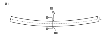
- FIG. 2 is a schematic diagram for explaining an example of the longitudinal shape of the base pipe 10; 2 schematically shows the shape of the II-II arrow cross-section of FIG. 1.
- FIG. Schematic cross-sectional shapes along the longitudinal direction of the pipe 10, the first mold 21 and the second mold 22 immediately after the pipe 10 is placed between the first mold 21 and the second mold 22.
- 4 schematically shows the shape of the cross section taken along line IV-IV of FIG. 3;
- 6 schematically shows the shape of the cross section taken along the line VI-VI of FIG. 5;
- FIG. 4 is a schematic diagram for explaining an example of the longitudinal shape of the hollow member 100; 8 schematically shows the shape of the VIII-VIII cross section of FIG. 7; 4 shows FEM analysis results for Comparative Example 1.
- FIG. 10 shows FEM analysis results for Comparative Example 2.
- FIG. 10 shows FEM analysis results for Comparative Example 3.
- FIG. 4 shows FEM analysis results for Example 1.
- FIG. 3 shows FEM analysis results for Example 2.
- a method for manufacturing a hollow member 100 includes: Placing the blank pipe 10 between the first mold 21 and the second mold 22 (see FIGS. 3 and 4), and By bringing the first mold 21 and the second mold 22 relatively close to each other and pressing the first mold 21 and the second mold 22 against the raw pipe 10, one or more pressings (see Figures 5 and 6); including.
- the base pipe 10 has a circular cross-sectional shape in at least a portion thereof.
- the first mold 21 has a first curved surface 21a.
- the second mold 22 has a second curved surface 22a. As shown in FIGS.
- the first curved surface 21a and the second curved surface 22a are pressed against at least a part of the raw pipe 10, so that the raw pipe 10 is subjected to bending and cross-sectional processing at the same time, and In the cross-sectional processing, the circular cross-sectional shape of the base pipe 10 is reduced in diameter.
- the diameter reduction rate in one press working is more than 0% and less than 10%.
- FIG. 1 illustrates a case where the blank pipe 10 is a curved pipe having a curved portion 10a.
- a straight pipe without curved portions may be used as the base pipe 10 .
- the radius of curvature of the curved portion 10a is reduced in the bending process, and the cross-sectional shape of the curved portion 10a is reduced in the cross-sectional process.
- a curved portion is formed in at least a part of the straight pipe in the bending process, and the cross-sectional shape of the curved part is reduced in diameter in the cross-sectional process.
- “Straight pipe” means any pipe that does not meet the definition of “bent pipe” below.
- a "curved portion” refers to a curved portion in the longitudinal shape of the pipe.
- the term “curved pipe” refers to a pipe having a curved portion and having a shape that satisfies the relationship of R ⁇ 300D between the radius of curvature R (minimum radius of inner bending) and the diameter D of the curved portion.
- the bent pipe When the base pipe 10 is a bent pipe, the bent pipe may be bent two-dimensionally or three-dimensionally at the bent portion 10a.
- the bent pipe In FIG. 1, the bent pipe is bent in the vertical direction of the paper surface at the bent portion 10a, but it may be bent further in the depth direction of the paper surface at the bent portion.
- the bending shape of the curved portion is not particularly limited.
- the curved tube may be curved at the bend. It should be noted that the bent pipe should not substantially have discontinuous surfaces such as wrinkles or buckling at the bent portion.
- the radius of curvature RA (minimum inner bending radius) of the curved portion 10a is not particularly limited as long as it is larger than the radius of curvature RB , which will be described later.
- the radius of curvature RA can be appropriately determined in consideration of the material, wall thickness, opening diameter (equivalent circle diameter) of the curved pipe, radius of curvature RB described later, and the like.
- the bending shape (ridgeline) in the longitudinal direction of the curved portion may be composed of only one circular arc, or may be composed of a combination of a plurality of circular arcs.
- the curvature may change continuously or discontinuously from one end in the longitudinal direction to the other end.
- the number of bent portions 10a provided in the bent pipe is not particularly limited.
- the curved pipe has only one curved portion 10a, but the curved pipe may have a plurality of curved portions 10a with the same or different curvature radii RA .
- the press work described below is performed on each of the plurality of curved portions 10a, the plurality of press work may be performed simultaneously, or may be performed separately at different timings.
- the bent pipe may have a straight pipe portion in addition to the bent portion 10a.
- the term “straight pipe portion” refers to a straight portion (a portion that satisfies R>300D) with no bends in the longitudinal shape of the pipe.
- the curved pipe may consist of only one or more curved portions 10a.
- the blank tube 10 does not need to be completely tubular as a whole.
- the base pipe 10 may partially have notches, slits, through holes, intentional unevenness, etc., depending on the application. These cutouts, slits, through holes, irregularities, etc. provided in the base pipe 10 may remain in the hollow member 100 .
- the cross-sectional shape of the portion of the tube 10 that is subjected to bending and cross-sectional processing may be an annular shape without discontinuity.
- the length of the base tube 10 is not particularly limited, and can be appropriately determined according to the application. However, if the length of the base pipe 10 is extremely short, it may be difficult to perform the bending process. In the base pipe 10, the length from one end to the other end in the longitudinal direction of the pipe (the length of the line LA continuously connecting the opening center (centroid)) is greater than the opening diameter (equivalent circle diameter) DA . can be longer.
- the “cross-sectional shape” of a pipe means a cross section perpendicular to the longitudinal direction of the pipe (with respect to the tangent to the line LA that continuously connects the opening centers (centroids) of the pipe). cross-sections perpendicular to each other), the shape defined by the outer wall surface of the tube. That is, "the circular cross-sectional shape is reduced” means that the outer diameter of the circular tube is reduced.
- the base pipe 10 has a circular cross-sectional shape at least in the portion where bending and cross-sectional processing are performed. For example, when the blank tube 10 is a curved tube as shown in FIGS.
- the cross-sectional shape of the base pipe 10 at 10a is circular.
- the cross-sectional shape of the base pipe 10 in the portion where bending and cross-sectional processing are not performed is not particularly limited, and may be circular, elliptical, flat circular, polygonal, rounded polygon, or a combination of these shapes. etc., various shapes are possible.
- the cross-sectional shape of the base pipe 10 may be substantially the same from one longitudinal end to the other, or may be continuous or discontinuous from one longitudinal end to the other. may have changed.
- the circular cross-sectional shape as described above is reduced in diameter by cross-sectional processing. That is, the cross-sectional processing reduces the diameter of the cross-sectional shape.
- "the length of a straight line that connects two points on the outer circumference (edge) of the cross-sectional shape of the base pipe and passes through the centroid of the cross-sectional shape” is defined as " defined as "diameter”.
- a cross-sectional shape having a ratio of major axis to minor axis (major axis/minor axis) of 1.0 or more and 2.0 or less (preferably 1.0 or more and 1.3 or less) is defined as "circular".
- the term "circular” is not limited to a true circle with (major axis/minor axis) equal to 1.0, but also includes an ellipse. are also considered to be circular. If the major axis/minor axis is within the range of 1.0 or more and 2.0 or less, remarkable effects can be expected from the production method of the present disclosure.
- the “circle” referred to in the present application may or may not have an outer peripheral portion that is convex toward the center of the circle (convex toward the inside of the cross-sectional shape). but preferably not.
- the thickness (thickness) t of the base pipe 10 is not particularly limited, and can be appropriately determined according to the application.
- the wall thickness t of the base pipe 10 may be, for example, 0.6 mm or more and 15.0 mm or less, or may be 1.0 mm or more and 10.5 mm or less.
- the ratio t/D of the wall thickness t to the tube diameter D of the blank tube 10 may be 0.012 or more and 0.206 or less.
- the wall thickness of the blank pipe 10 may differ from part to part.
- the material of the base pipe 10 may be any material that allows press working, and can be appropriately determined according to the application.
- it may be made of metal such as steel, iron, aluminum, titanium, or magnesium.
- the manufacturing method of the present disclosure is a high-strength steel pipe made of high-strength steel having a tensile strength of 290 MPa or more, 440 MPa or more, 590 MPa or more, or 780 MPa or more measured at room temperature in accordance with JIS Z 2241:2011, It can also be applied to high-strength steel pipes made of ultra-high-strength steel with a tensile strength of 980 MPa or more.
- a method for obtaining the element pipe 10 is not particularly limited.
- the straight pipe may be manufactured by a known method.
- the blank pipe 10 may or may not have a seam formed by welding or the like.
- the base pipe 10 is a curved pipe having a curved portion 10a
- the curved pipe may be obtained by, for example, at least bending a straight pipe, or the curved portion 10a It may be obtained by at least bending a tube having a curved portion with a radius of curvature larger than that of the tube.
- a curved pipe having a curved portion 10a as the base pipe 10 may be obtained by subjecting a straight pipe or a curved pipe to at least bending and cross-sectional processing.
- the bending method for obtaining the bent pipe is not particularly limited.
- a curved pipe may be obtained by press-working a straight pipe from the outside of the pipe. That is, the bending process for obtaining the bent tube as the blank tube 10 may be performed by applying pressure from the outside of the tube toward the inside of the tube using a press die.
- a press die may be used to process the cross section. That is, the bending and cross-sectional processing for obtaining the bent pipe as the base pipe 10 may be performed by applying pressure from the outside of the pipe toward the inside of the pipe using a press die.
- a press die for obtaining a bent tube as the blank tube 10 and a press die (a first die 21 and a second die 22) for obtaining the hollow member 100 from the blank tube 10 to be described later. and should be used properly.
- the press working for obtaining the bent pipe as the base pipe 10 and the press working for obtaining the hollow member 100 from the base pipe 10 are performed using the same press machine. can also In other words, it is possible to improve the productivity and the like by sharing the equipment for manufacturing the blank tube 10 and the equipment for manufacturing the hollow member 100 .
- the method for obtaining the bent pipe is not limited to the press working method using the press mold described above.
- a curved pipe as the blank pipe 10 may be obtained by performing conventionally known bending processes such as rotary drawing bending (pipe bender), tension bending, pressing bending, pushing through bending, and roll bending.
- rotary drawing bending pipe bender
- tension bending pressing bending
- pushing through bending and roll bending.
- first mold 21 and a second mold 22 are used as press dies.
- other molds may be used in the manufacturing method of the present disclosure.
- each of the first mold 21 and the second mold 22 corresponds to the longitudinal shape of the hollow member 100 described later.
- the first mold 21 has a first curved surface 21a.
- the first curved surface 21a can be convex in its longitudinal shape.
- the second mold 22 has a second curved surface 22a.
- the second curved surface 22a can be concave in its longitudinal shape.
- convex surface refers to a curved surface that is convex toward the blank tube in a cross section along the longitudinal direction of the mold and blank tube.
- the term “concave surface” refers to a curved surface that is concave with respect to the blank pipe in a cross section along the longitudinal direction of the die and blank pipe.
- the first curved surface 21a and the second curved surface 22a are pressed against at least a portion of the raw pipe 10, so that at least a portion of the raw pipe 10 is subjected to cross-sectional processing and bending. applied at the same time. That is, the first curved surface 21a and the second curved surface 22a function as press surfaces for the blank pipe 10 respectively.
- the curvature radii of the first curved surface 21a and the second curved surface 22a may be determined according to the curvature radius RB of the curved portion 100a of the hollow member 100, which will be described later.
- the radius of curvature RM (minimum inner bending radius, see FIG. 3) of the first curved surface 21a of the first mold 21 may be the same as the radius of curvature RB of the curved portion 100a of the hollow member 100, It can be smaller than that.
- the longitudinal shape of the portion other than the first curved surface 21a and the second curved surface 22a is, for example, the portion of the longitudinal shape of the hollow member 100 other than the curved portion 100a. It may be determined as appropriate according to the longitudinal shape of the .
- the longitudinal shape of the portion other than the first curved surface 21a and the second curved surface 22a may be linear or curved.
- the cross-sectional shape of the first mold 21 and the second mold 22 may be a shape that can reduce the diameter of the circular cross-sectional shape in the cross-sectional processing of the blank pipe 10. .
- the first mold 21 and the second mold 22 are integrated (the first mold 21 and the second mold 22 are The mold opening shape determined by the first mold 21 and the second mold 22 when the two molds 22 are closed is smaller than the cross-sectional shape of the blank pipe 10 and similar to the cross-sectional shape of the blank pipe 10. can be anything.
- the opening shape of the mold is smaller than the cross-sectional shape of the blank pipe 10, and the shape of the opening of the mold is similar to the cross-sectional shape of the blank pipe 10, so that the cross-sectional shape of the blank pipe 10 is reduced by cross-sectional processing.
- a more uniform pressure can be applied to the outer circumference of the raw pipe 10 when the diameter is reduced.
- the mold opening shape determined by the first mold 21 and the second mold 22 when the first mold 21 and the second mold 22 are integrated depends on the cross-sectional shape of the blank pipe 10 and the hollow member 100. It may be determined as appropriate. For example, as shown in FIG. 4, when the first mold 21 is the upper mold and the second mold 22 is the lower mold, the first mold 21 faces the upper end 10x of the blank tube 10.
- the second mold 22 may have a bottom portion (upper end portion) 21x and a side wall portion 21y facing the side portion 10y of the raw pipe 10.
- the second mold 22 has a bottom portion (lower end portion) facing the lower end 10z of the raw pipe 10. ) 22z and a side wall portion 22y facing the side portion 10y of the blank tube 10 . Further, as shown in FIG.
- Materials for the first mold 21 and the second mold 22 are not particularly limited, and general materials for molds can be adopted.
- the first curved surface 21 a and the second curved surface 21 a and the second curved surface 21 a with respect to the blank pipe 10 are moved by relatively moving the first mold 21 and the second mold 22 closer to each other.
- pressure is applied from the outer side of the raw pipe 10 toward the inner side thereof.
- the first mold 21 is the upper mold and the second mold 22 is the lower mold
- at least one of the first mold 21 and the second mold 22 is One of them should be moved up and down. That is, the raw pipe 10 is pressed from above and below to press the first curved surface 21a from above and the second curved surface 22a from below against at least a part of the raw pipe 10 .
- the first mold 21 and the second mold 22 may be moved manually, or may be moved mechanically and/or automatically by a driving device or the like.
- the first mold 21 and the second mold 22 have the first curved surface 21a and the second curved surface 22a as press surfaces, so that the press surfaces are By simply pressing against at least a part of the raw pipe 10, it is possible to bend the raw pipe 10 corresponding to the first curved surface 21a and the second curved surface 22a.
- the manufacturing method of the present disclosure even if the first curved surface 21a and the second curved surface 22a are pressed against the blank pipe 10 by linearly approaching the first mold 21 and the second mold 22, good.
- the first mold and the second mold are linearly approached means that at least one of the first mold 21 and the second mold 22 is moved to move the first mold 21 and the second mold 22 is brought relatively close to each other, and when a certain point of the moving mold is focused, the trajectory drawn by the point is linear.
- at least one of the first mold 21 and the second mold 22 needs only to be moved uniaxially (one-dimensionally) during press working.
- the press surface for performing cross-sectional processing and bending is configured with a curved surface, so that the blank tube 10 can be bent without rotating or turning the die or blank tube. Machining is possible. That is, in the manufacturing method of the present disclosure, in cross-section processing and bending, a complicated mechanism for rotating or turning the mold, or a complicated mechanism for rotating or turning the blank pipe such as rotary draw bending. No special mechanism is required.
- the blank pipe 10 is arranged between the first mold 21 and the second mold 22 .
- the first mold 21 and the second mold 22 may be arranged so as to face each other with the blank pipe 10 interposed therebetween.
- the first mold 21 and the second mold 22 are arranged so as to sandwich the blank pipe 10 from above and below. I wish I could.
- the portion on the one end side in the longitudinal direction of the blank pipe 10 and the other end side of the blank pipe 10 are separated. At least two parts of the base pipe 10 are brought into contact with the second mold 22, and parts other than the part on the one end side in the longitudinal direction and the part on the other end side of the base pipe 10 (for example, the central part in the longitudinal direction of the base pipe 10) At least one location may be in contact with the first mold 21 . In this manner, immediately after the blank pipe 10 is brought into contact with each of the first mold 21 and the second mold 22, at least three portions of the blank pipe 10 are brought into contact with the first mold 21 and the second mold 22. By being supported in contact with each other, misalignment or the like of the blank pipe 10 with respect to the mold can be easily suppressed during press working.
- FIGS. 3 to 6 show an embodiment in which the hollow member 100 is press-worked so that the curved portion 100a of the hollow member 100 protrudes downward. It may be processed.
- the second mold 22 is the lower mold, the second curved surface 22a of the second mold 22 protrudes downward, and the curved portion 100a of the hollow member 100 protrudes downward, the blank pipe 10 is better. is easy to place and position on the second mold 22, and it is thought that workability during press working is excellent.
- the direction of pressing by the first mold 21 and the second mold 22 is not limited to the vertical direction as shown in FIGS. . However, in consideration of workability, productivity, etc., the direction of pressing by the first mold 21 and the second mold 22 is preferably the vertical direction.
- a known press can be adopted as a press on which the first mold 21 and the second mold 22 are installed.
- the blank pipe 10 is subjected to press processing one or more times.
- the first curved surface 21a of the first mold 21 and the second curved surface 22a of the second mold 22 are pressed against at least a part of the blank pipe 10 from the outside, thereby forming the pipe.
- Material flow is generated in the circumferential direction, and the cross-sectional shape of the base pipe 10 is reduced in diameter.
- the diameter (outer diameter) DA in the cross-sectional shape of the hollow member 10 is reduced by cross-sectional processing, and the diameter (outer diameter) DA in the cross-sectional shape of the hollow member 100 is reduced . and change.
- the diameter reduction ratio in one press working is more than 0% and less than 10%. If the diameter reduction rate in one press working is 10% or more, the die is likely to be bitten and the tube is likely to buckle.
- the diameter reduction rate in one press working may be 1% or more, 2% or more, 3% or more, 4% or more, or 5% or more, and may be 9% or less, 8% or less, 7% or less, or It may be 6% or less.
- the diameter reduction rate in one press working is more than 0% and 6% or less, it is easy to obtain the hollow member 100 with even better surface properties.
- the diameter reduction rate is calculated by the following formula.
- the term "diameter reduction” refers to a reduction in an arbitrary diameter in a circular cross-sectional shape, and refers to a reduction in the length of the outer periphery of a circular cross-sectional shape.
- processing involving "diameter expansion" in at least a part of the cross-sectional shape such as flattening a circular tube into an elliptical tube, corresponds to "reducing the diameter of a circular cross-sectional shape" in the present application. do not.
- pressure is applied from the outside to the inside of the raw pipe 10 during cross-sectional processing. That is, in the manufacturing method of the present disclosure, pressure is not applied from the inside to the outside of the tube as in hydroforming, but the cross-sectional shape of the raw tube 10 is changed only by press working from the outside of the tube.
- a core mold or the like may be installed inside the pipe, for example, at the end of the pipe. As a result, it is possible to further suppress dents, crushing, and the like at the pipe ends and the like.
- a gap is generated between the outer wall of the hollow member 100 and the inner walls of the first mold 21 and the second mold 22 in the cross section perpendicular to the longitudinal direction of the hollow member 100. There may be no gap.
- cross-sectional processing is optional for portions other than the portion that is bent and becomes the curved portion 100a.
- the straight pipe portion may or may not be subjected to cross-sectional processing.
- different cross-sectional processing may be performed on the curved portion 100a and the straight pipe portion.
- the base tube 10 has a plurality of curved portions 10a, one curved portion 10a and the other curved portion 10a may be subjected to the same cross-sectional processing or different cross-sectional processing.
- the blank tube 10 is pressed one or more times.
- at least a portion of the base pipe 10 is subjected to bending as well as the cross-sectional working described above. That is, the first curved surface 21a of the first mold 21 and the second curved surface 22a of the second mold 22 are pressed from the outside of the blank pipe 10, so that at least a part of the blank pipe is bent in the longitudinal direction of the pipe.
- Material flow is generated to form a curved portion 100a with a small radius of curvature.
- the bending process changes a curved portion 10a having a radius of curvature R A to a curved portion 100a having a radius of curvature R B .
- the curved portion 100a is formed in the raw pipe 10 only by pressing from the outside of the pipe without applying pressure from the inside to the outside of the pipe as in hydroforming. do.
- a gap may or may not occur between the outer wall of the hollow member 100 and the press die in the longitudinal direction of the hollow member 100 when the bending process is completed.
- any portion other than the portion where the curved portion 100a is formed may be bent.
- the hollow member 100 having the curved portion 100a and curved portions and/or straight pipe portions other than the curved portion 100a may be manufactured by bending only a portion of the base pipe 10. .
- the cross-sectional processing and bending are performed at the same time. That is, in at least a part of the blank pipe 10 during press working, the material flow in the circumferential direction and the material flow in the longitudinal direction of the pipe are allowed to proceed at the same time, so that the hollow member 100 after press working has high shape accuracy. Secured.
- the material flow in the circumferential direction and the longitudinal direction of the tube is likely to occur because the cross-sectional shape of the blank pipe 10 is reduced in the cross-sectional process at the same time as the bending process. The occurrence of bending is easily suppressed.
- the cross-section processing and the bending processing need only proceed at the same time at a certain point in time. It does not have to be strictly simultaneous.
- the period from the contact of the first mold 21 and the second mold 22 to the blank pipe 10 to the completion of the press working is divided into the first half and the second half.
- at least part of the raw pipe 10 may be cross-sectionally processed and bent at some point in the latter half of the process.
- a minimum radius of curvature may be identified. That is, when the blank tube 10 is press-worked, bending is performed so that the curvature radius R B is equal to or greater than the minimum curvature radius R B-min that has been confirmed in advance. Occurrence can be further suppressed.
- the above-described press working is applied to the blank tube 10 one or more times.
- the number of press working may be two or more, three or more, four or more, or five or more.
- the diameter reduction rate in each press working is preferably more than 0% and less than 10%.
- the diameter reduction rate in each press work may be 1% or more, 2% or more, 3% or more, 4% or more, or 5% or more, and may be 9% or less, 8% or less, 7% or less, or 6%. % or less.
- hollow member 100 with even better surface properties can be easily obtained when the diameter reduction rate in each press work is more than 0% and 6% or less.
- the second press work with diameter reduction of more than 0% and less than 10% is performed. good too.
- the diameter reduction rate in each press work may be the same or different.
- the ratio of diameter reduction in the first pressing may be larger, smaller, or the same as that in the second pressing.
- the blank tube 10 is subjected to the above-described press working in two or more steps, making it easier to further reduce the radius of curvature RB at the curved portion 100a of the hollow member 100 .
- the hollow member 100 has a curved portion 100a at least in part.
- the longitudinal direction of the hollow member 100 can correspond to the longitudinal direction of the blank tube 10 before press working.
- the hollow member 100 may be bent two-dimensionally or three-dimensionally at the bent portion 100a.
- the hollow member 100 is bent vertically in the curved portion 100a, but it may be further bent forward in the curved portion 100a.
- the bending shape of the bending portion 100a is not particularly limited.
- hollow member 100 may be curved at curved portion 100a.
- the radius of curvature RB (minimum inner bending radius) of the curved portion 100a is not particularly limited.
- the radius of curvature RB should be smaller than the radius of curvature RA described above.
- the bending shape (ridge line) of the curved portion 100a in the longitudinal direction may be composed of only one circular arc, or may be composed of a combination of a plurality of circular arcs.
- the curvature may change continuously or discontinuously from one end in the longitudinal direction to the other end.
- FIG. 7 shows a configuration in which the hollow member 100 has only one curved portion 100a
- the hollow member 100 may have multiple curved portions 100a with the same or different curvature radii RB .
- the hollow member 100 may have a straight pipe portion in addition to the curved portion 100a.
- the hollow member 100 may consist of only one or more curved portions 100a.
- the hollow member 100 need not be entirely tubular.
- the hollow member 100 may partially have a notch or a slit.
- the hollow member 100 may partially have through holes or intentional irregularities.
- the length of the hollow member 100 is not particularly limited, and can be appropriately determined according to the application.
- the length of the hollow member 100 may be the same as or different from the length of the blank tube 10 .
- the hollow member 100 may be longer than the base pipe 10 because the cross-sectional shape is reduced in diameter by processing the cross-section.
- the cross-sectional shape of the hollow member 100 is circular at the curved portion 100a.
- the cross-sectional shape of the hollow member 100 at the portion other than the curved portion 100a is not particularly limited, and may be circular, elliptical, flat circular, polygonal, rounded polygon, combinations of these shapes, and the like. can have the shape of The cross-sectional shape of the hollow member 100 can be appropriately determined according to its use. By changing the cross-sectional shape of the first mold 21 and the second mold 22 described above, the cross-sectional shape of the hollow member 100 can be easily changed.
- the cross-sectional shape of the hollow member 100 may be the same from one end in the longitudinal direction of the pipe to the other end, or may change continuously or discontinuously from one end to the other end in the longitudinal direction of the pipe. may Further, when the hollow member 100 has a straight pipe portion as well as the curved portion 100a, the curved portion 100a and the straight pipe portion may have the same cross-sectional shape, or may have different cross-sectional shapes. Moreover, when the hollow member 100 has a plurality of curved portions 100a, the respective curved portions 100a may have the same cross-sectional shape, or may have different cross-sectional shapes.
- the thickness (thickness) of the hollow member 100 is not particularly limited, and can be appropriately determined according to the application.
- the thickness of hollow member 100 may vary from portion to portion.
- the thickness T1 on the inner side of the bend tends to be thicker, while the thickness T2 on the outer side of the bend tends to be excessively thin.
- the thickness T 1 on the inner side of the bend and the thickness T 2 on the outer side of the bend at the bent portion 100a are compared to those obtained by conventional rotary draw bending. As a result, the thickness reduction on the outer side of the bend is likely to be suppressed. This is because, as described above, the pipe material flows in the circumferential direction due to the bending and the cross-sectional processing performed at the same time.
- the blank pipe 10 is pressed, and at least part of the blank pipe 10 is subjected to cross-sectional processing and bending simultaneously. As a result, molding defects (wrinkles, buckling, etc.) at the curved portion 100a of the hollow member 100 can be suppressed.
- the manufacturing method of the present disclosure can also be applied to manufacturing tapered tubes, for example. That is, a tapered tube as the hollow member 100 may be obtained by cross-sectional processing according to the manufacturing method of the present disclosure, or a tapered tube may be used as the base tube 10 for obtaining the hollow member 100 .
- One Example of Applications of Hollow Member Applications of the hollow member 100 obtained by the manufacturing method of the present disclosure are diverse.
- automobile parts such as bumper beams, suspension members, side rails, trailing arms, upper arms, pillars, torsion beams, door impact beams, instrument panel beams, and the like.
- Comparative Example 2 A straight pipe as a base pipe was subjected to press bending multiple times in increments of R600 to R100 to examine how far it could be bent without wrinkling or buckling. The cross-sectional shape before and after bending was assumed to be substantially unchanged. As a result, as shown in FIG. 10, bending was possible up to R400 without wrinkling or buckling, but wrinkles were generated at the curved portion of R300, and large wrinkles were generated at the curved portion of R200. Compared with Comparative Example 1, Comparative Example 2 was able to suppress molding defects, but even so, wrinkles and buckling could be suppressed up to R400.
- the major axis of the ellipse is aligned vertically, and the minor axis is aligned horizontally. Furthermore, the length of the outer circumference of the cross-sectional shape was not substantially changed before and after the cross-sectional processing. As a result, a curved portion having R200 could be formed without causing wrinkles or buckling on the inner side of the bend, but lines and wrinkles originating from the boundary of the mold occurred on the side surface of the bend at R300. .
- Example 1 A straight pipe as a base pipe was subjected to press bending multiple times in increments of R600 to R100 to examine how far it could be bent without wrinkling or buckling.
- a cross-sectional process was performed to reduce the cross-sectional shape of the pipe by 1%.
- bending was possible up to R200 without wrinkles or buckling.
- wrinkles were generated at the curved portion of R150.
- Example 2 A straight pipe as a base pipe was subjected to press bending multiple times in increments of R600 to R100 to examine how far it could be bent without wrinkling or buckling.
- a cross-sectional process was performed to reduce the cross-sectional shape of the pipe by 2%.
- FIG. 13 bending was possible up to R200 without wrinkles or buckling.
- Example 2 compared with Example 1, the degree of wrinkles could be reduced and the bending limit was improved.
- Example 3 A straight pipe as a base pipe is press-bent multiple times in the same manner as in Comparative Example 2 from R600 to R400 in R100 increments without changing the cross-sectional shape of the pipe, and further from R400 to R200 in R100 increments. , press bending was performed along with cross-sectional processing to reduce the cross-sectional shape of the pipe by 6%. As a result, wrinkles at the curved portions of R300 and R200 were significantly reduced as compared with Comparative Example 2. However, after that, when press bending was performed together with cross-sectional processing to reduce the cross-sectional shape of the pipe by 6% from R200 to R150, large wrinkles and buckling occurred.
- Comparative Example 4 A straight pipe as a base pipe was subjected to press bending from R600 to R500. Here, simultaneously with the bending process, a cross-sectional process was performed to reduce the cross-sectional shape of the pipe by 12%. In this case, the diameter reduction ratio is excessively large, and large wrinkles and buckling occur in the pipe, making appropriate bending difficult.
- Table 1 below summarizes the results of Comparative Examples 1 to 4 and Examples 1 to 3.
- “A”, “B” and “C” respectively mean the following. Further, “A to B” means that it is intermediate between A and B, and “B to C” means that it is intermediate between B and C.
- C Large wrinkles and buckling occur at curved portions.
- a method for manufacturing a hollow member Placing the blank tube between the first mold and the second mold, and Pressing the blank pipe at least once by bringing the first mold and the second mold relatively closer together and pressing the first mold and the second mold against the blank pipe.
- At least part of the base pipe has a circular cross-sectional shape
- the first mold has a first curved surface
- the second mold has a second curved surface
- the first curved surface and the second curved surface are pressed against at least a portion of the raw pipe, so that at least a portion of the raw pipe is subjected to cross-sectional processing and bending.
- the cross-sectional processing the circular cross-sectional shape of the base pipe is reduced in diameter, and
- the diameter reduction rate in one press working is more than 0% and less than 10%. Production method.
Landscapes
- Engineering & Computer Science (AREA)
- Mechanical Engineering (AREA)
- Bending Of Plates, Rods, And Pipes (AREA)
- Shaping Metal By Deep-Drawing, Or The Like (AREA)
Abstract
Description
<態様1>
中空部材の製造方法であって、
第1金型及び第2金型の間に素管を配置すること、並びに、
前記第1金型及び前記第2金型を相対的に近づけて、前記第1金型及び前記第2金型を前記素管に押し付けることで、前記素管に対して1回以上のプレス加工を施すこと、
を含み、
前記素管が、その少なくとも一部において、円形である断面形状を有し、
前記第1金型が、第1曲面を有し、
前記第2金型が、第2曲面を有し、
1回の前記プレス加工において、前記素管の少なくとも一部に対して前記第1曲面及び前記第2曲面が押し付けられることで、前記素管の少なくとも一部に対して断面加工と曲げ加工とが同時に施され、
前記断面加工において、前記素管の前記円形である前記断面形状が縮径され、且つ、
1回の前記プレス加工における縮径率が、0%超10%未満である、
製造方法。
<態様2>
前記プレス加工が、2回以上施され、且つ、
各々の前記プレス加工における縮径率が、0%超10%未満である、
態様1の製造方法。
<態様3>
前記第1金型及び前記第2金型が直線的に近づけられて、前記第1曲面及び前記第2曲面が前記素管に押し付けられる、
態様1又は2の製造方法。
<態様4>
前記断面加工及び前記曲げ加工が施される部分において、前記第1金型及び前記第2金型が一体となった際に前記第1金型及び前記第2金型によって定まる金型開口形状が、前記素管の前記断面形状よりも小さく、且つ、前記素管の前記断面形状と相似する、
態様1~3のいずれかの製造方法。
<態様5>
1回の前記プレス加工における縮径率が、0%超6%以下である、
態様1~4のいずれかの製造方法。
<態様6>
前記素管が曲部を有する曲管であり、
前記曲げ加工において、前記曲部の曲率半径が小さくされ、
前記断面加工において、前記曲部の断面形状が縮径される、
態様1~5のいずれかの製造方法。
<態様7>
前記素管が直管であり、
前記曲げ加工において、前記直管の少なくとも一部に曲部が形成され、
前記断面加工において、前記曲部の断面形状が縮径される、
態様1~5のいずれかの製造方法。
<態様8>
前記第1金型が上金型であり、
前記第2金型が下金型であり、
前記断面加工及び前記曲げ加工において、前記第1金型及び前記第2金型のうちの少なくとも一方が上下方向に移動する、
態様1~7のいずれかの製造方法。
<態様9>
1回の前記プレス加工において、前記第1金型及び前記第2金型が前記素管に接触してから、前記プレス加工が完了するまでの間を、前半と後半との2つに分けた場合、少なくとも後半におけるいずれかの時点において、前記素管の少なくとも一部に対して前記断面加工と前記曲げ加工とが同時に施される、
態様1~8のいずれかの製造方法。
第1金型21及び第2金型22の間に素管10を配置すること(図3及び4参照)、並びに、
前記第1金型21及び前記第2金型22を相対的に近づけて、前記第1金型21及び前記第2金型22を前記素管10に押し付けることで、前記素管10に対して1回以上のプレス加工を施すこと(図5及び6参照)、
を含む。
図1及び2に示されるように、前記素管10は、その少なくとも一部において、円形である断面形状を有する。
図3及び4に示されるように、前記第1金型21は、第1曲面21aを有する。
図3及び4に示されるように、前記第2金型22は、第2曲面22aを有する。
図5及び6に示されるように、1回の前記プレス加工においては、前記素管10の少なくとも一部に対して前記第1曲面21a及び前記第2曲面22aが押し付けられることで、前記素管10の少なくとも一部に対して曲げ加工と断面加工とが同時に施され、且つ、
前記断面加工において、前記素管10の前記円形である前記断面形状が縮径される。
ここで、1回の前記プレス加工における縮径率は、0%超10%未満である。
1.1 素管の長手形状
図1に、素管10が曲部10aを有する曲管である場合を例示する。ただし、本開示の製造方法においては、素管10として曲部を有しない直管が用いられてもよい。本開示の製造方法において、素管10が曲部10aを有する曲管である場合、曲げ加工において、曲部10aの曲率半径が小さくされ、断面加工において、曲部10aの断面形状が縮径されてもよい。また、本開示の製造方法において、素管10が直管である場合、曲げ加工において、直管の少なくとも一部に曲部が形成され、断面加工において、曲部の断面形状が縮径されてもよい。「直管」とは、以下の「曲管」の定義を満たさないものをいう。「曲部」とは管長手形状において曲がった部分をいう。「曲管」とは、曲部を有する管をいい、曲部における曲率半径R(内側曲げ最小半径)と管直径DとがR≦300Dなる関係を満たす形状を有するものをいう。
本願において、管の「断面形状」とは、管の長手方向と直交する断面(管の開口中心(図心)を連続的に結んだ線LAの接線に対して直交する断面)において、管の外壁面によって画定される形状である。すなわち、「円形である断面形状が縮径される」とは、円形管の外径が縮径されることを意味する。図2に示されるように、素管10は、少なくとも曲げ加工及び断面加工が施される部分において、円形である断面形状を有する。例えば、図1及び2に示されるように素管10が曲管であり、且つ、図3~6に示されるようにプレス加工によって曲部10aの曲率半径が小さくされる場合、少なくとも当該曲部10aにおける素管10の断面形状が円形である。曲げ加工及び断面加工が施されない部分における素管10の断面形状は、特に限定されるものではなく、円形の他、楕円形、偏平円形、多角形、丸みを帯びた多角形、これら形状の組み合わせ等、種々の形状があり得る。素管10の断面形状は、管長手方向一端から他端に向かって実質的に変化がなく同じ形状であってもよいし、管長手方向一端から他端に向かって連続的又は不連続的に変化していてもよい。
素管10の材質は、プレス加工が可能な材質であればよく、用途に応じて適宜決定され得る。例えば、鋼、鉄、アルミニウム、チタン、マグネシウム等の金属製としてもよい。本開示の製造方法は、JIS Z 2241:2011に準拠して室温で測定される引張強さが290MPa以上、440MPa以上、590MPa以上又は780MPa以上の高張力鋼からなる高強度鋼管や、当該引張強さが980MPa以上の超高張力鋼からなる高強度鋼管に対しても適用可能である。
素管10を得る方法は特に限定されるものではない。素管10が直管である場合、当該直管は、公知の方法により製造されたものであればよい。素管10には溶接等による継目があってもよいし、なくてもよい。素管10が曲部10aを有する曲管である場合、当該曲管は、例えば、直管に対して少なくとも曲げ加工を施すことによって得られたものであってもよいし、或いは、曲部10aよりも曲率半径の大きな曲部を有する管に対して少なくとも曲げ加工を施すことによって得られたものであってもよい。また、直管又は曲管に対して、少なくとも曲げ加工と断面加工とを施すことで、素管10として曲部10aを有する曲管を得てもよい。
図3~6に示されるように、本開示の製造方法においては、プレス金型として少なくとも第1金型21及び第2金型22が用いられる。尚、本開示の製造方法においては、第1金型21及び第2金型22に加えて、その他の金型が用いられてもよい。
第1金型21及び第2金型22の各々の長手形状は、後述する中空部材100の長手形状と対応する。図3~6に示されるように、第1金型21は第1曲面21aを有する。第1曲面21aは、長手形状において凸面となり得る。また、第2金型22は第2曲面22aを有する。第2曲面22aは、長手形状において凹面となり得る。「凸面」とは、金型及び素管の長手方向に沿った断面において、素管に向かって凸となっている曲面をいう。また、「凹面」とは、金型及び素管の長手方向に沿った断面において、素管に対して凹となっている曲面をいう。本開示の製造方法においては、これら第1曲面21aと第2曲面22aとが素管10の少なくとも一部に押し付けられることで、素管10の少なくとも一部に対して断面加工と曲げ加工とが同時に施される。すなわち、第1曲面21a及び第2曲面22aは、各々、素管10に対するプレス面として機能する。金型及び素管の長手方向に沿った断面において、第1曲面21a及び第2曲面22aの曲率半径は、後述する中空部材100の曲部100aの曲率半径RBに応じて決定されればよい。例えば、第1金型21の第1曲面21aの曲率半径RM(内側曲げ最小半径、図3参照)は、中空部材100の曲部100aの曲率半径RBと同じであってもよいし、それより小さくてもよい。
第1金型21及び第2金型22の断面形状は、素管10の断面加工において、円形である断面形状を縮径することが可能な形状であればよい。例えば、本開示の製造方法においては、上記の曲げ加工と断面加工とが施される部分において、第1金型21及び第2金型22が一体となった際(第1金型21及び第2金型22が閉じた際)に第1金型21及び第2金型22によって定まる金型開口形状が、素管10の断面形状よりも小さく、且つ、素管10の断面形状と相似するものであってよい。このように、金型の開口形状が素管10の断面形状よりも小さく、且つ、金型開口形状が素管10の断面形状と相似することで、断面加工によって素管10の断面形状を縮径する際、素管10の外周に対してより均一に圧力を付与することができる。
第1金型21及び第2金型22の材質は特に限定されるものではなく、金型として一般的な材質を採用可能である。
本開示の製造方法においては、まず、第1金型21及び第2金型22の間に素管10を配置する。図3及び4に示されるように、第1金型21及び第2金型22は、素管10を間に挟んで互いに対向するように配置されればよい。例えば、第1金型21が上金型で、第2金型22が下金型である場合、第1金型21と第2金型22とが、素管10を上下から挟み込むように配置されればよい。
本開示の製造方法においては、素管10に対して1回以上のプレス加工を施す。1回のプレス加工においては、素管10の少なくとも一部に対して、第1金型21の第1曲面21aと第2金型22の第2曲面22aとを外側から押し付けることで、管の周方向への材料流動を生じさせ、素管10の断面形状を縮径させる。例えば、図2及び8に示されるように、断面加工によって、素管10の断面形状における直径(外径)DAが縮径され、中空部材100の断面形状における直径(外径)DBへと変化する。ここで、本開示の製造方法においては、1回のプレス加工における縮径率が0%超10%未満であることが重要である。1回のプレス加工における縮径率が10%以上であると、金型に噛み疵が発生し易く、また、管が座屈し易い。1回のプレス加工における縮径率は、1%以上、2%以上、3%以上、4%以上又は5%以上であってもよく、且つ、9%以下、8%以下、7%以下又は6%以下であってもよい。特に、1回のプレス加工における縮径率が0%超6%以下である場合に、表面性状に一層優れた中空部材100が得られ易い。尚、縮径率は、以下の式により算出される。以下の式の通り、縮径率は、断面加工前の素管10の直径DAを基準に算出される。例えば、直径DAの素管10に対してプレス加工を10回行い、且つ、各々のプレス加工における縮小径率が2%である場合、10回のプレス加工の合計の縮径率は20%であり、最終的に得られる中空部材100の直径DBは0.80DAとなる。
縮径率(%)=[1-(断面加工後の中空部材の断面直径/断面加工前の素管の断面直径)]×100
本開示の製造方法においては、上述の通り、素管10に対して1回以上のプレス加工を施す。プレス加工により、素管10の少なくとも一部に対して、上記の断面加工とともに、曲げ加工が施される。すなわち、第1金型21の第1曲面21aと第2金型22の第2曲面22aとが素管10の管外側から押し付けられることで、素管の少なくとも一部において管の長手方向への材料流動を生じさせ、曲率半径の小さな曲部100aを形成する。例えば、図1~8に示されるように、曲げ加工によって、曲率半径RAの曲部10aを、曲率半径RBの曲部100aへと変化させる。
6.1 中空部材の長手形状
図7に示されるように、中空部材100は少なくとも一部に曲部100aを有する。中空部材100の長手方向は、プレス加工前の素管10の長手方向と対応し得る。中空部材100は曲部100aにおいて2次元的に曲げられていてもよいし、3次元的に曲げられていてもよい。例えば、図7においては、中空部材100が曲部100aにおいて紙面上下方向に曲げられた形態を示したが、当該曲部100aにおいてさらに紙面奥手前方向に曲げられていてもよい。曲部100aにおける曲げ形状は特に限定されるものではない。例えば、中空部材100は曲部100aにおいて湾曲していてもよい。上述した第1金型21の第1曲面21a及び第2金型22の第2曲面22aの形状を変更することで、中空部材100の曲げ形状を容易に変更できる。
図8に示されるように、中空部材100の断面形状は、曲部100aにおいて円形である。曲部100a以外の部分における中空部材100の断面形状は、特に限定されるものではなく、円形の他、楕円形、偏平円形、多角形、丸みを帯びた多角形、これら形状の組み合わせ等、種々の形状があり得る。中空部材100の断面形状は、その用途に応じて適宜決定され得る。上述した第1金型21及び第2金型22の断面形状を変更することで、中空部材100の断面形状を容易に変更できる。
本開示の製造方法により得られる中空部材100の用途は多岐に亘る。例えば、バンパービーム、サスペンションメンバー、サイドレール、トレーリングアーム、アッパーアーム、ピラー、トーションビーム、ドアインパクトビーム、インストルメントパネルビーム等の自動車の部品等である。
1.1 比較例1
素管としての直管(440MPa級鋼からなる円管、φ60.5mm、厚み2.3mm、全長380mm)に対してプレス金型を用いて、1工程で皺や座屈なくどこまで曲げられるかを検討した。曲げ加工前後における断面形状は実質的に変化させないものとした。検討にはFEM解析を利用した。結果を図9に示す。図9に示されるように、400mmの曲率半径(R400)を有する曲部を形成する場合、皺や座屈なく曲げ加工が可能であったものの、R300の曲部においては皺が生じ、R200の曲部においては座屈して大きな凹みが生じた。
素管としての直管に対して、R600からR100刻みで複数回プレス曲げを行い、皺や座屈なくどこまで曲げられるかを検討した。曲げ加工前後における断面形状は実質的に変化させないものとした。その結果、図10に示されるように、R400までは皺や座屈なく曲げ加工が可能であったものの、R300の曲部においては皺が生じ、R200の曲部においては大きな皺が生じた。比較例2は、比較例1と比べて、成形不良を抑えることができたが、それでも、皺や座屈を抑えることができたのではR400までであった。
素管としての直管に対してプレス金型を用いて、曲げ加工と同時に断面加工を施すことで、皺や座屈なくどこまで曲げられるかを検討した。具体的には、図11に示されるように、直管に対してR600からR400、R400からR300、R300からR200へと「曲げ加工と同時に、断面形状を真円から楕円に変形させる断面加工」と「曲げ加工と同時に、断面形状を楕円から真円に変形させる断面加工」とを交互に行った。ここで、楕円形の長径を鉛直方向に一致させ、短径を水平方向に一致させるものとした。さらに、断面加工前後で、断面形状の外周の長さは実質的に変化させないものとした。その結果、曲げ内側に皺や座屈を生じさせることなく、R200を有する曲部を形成することができたものの、R300の時点で曲げ側面に金型の境界に由来するラインや皺が生じた。
素管としての直管に対して、R600からR100刻みで複数回プレス曲げを行い、皺や座屈なくどこまで曲げられるかを検討した。ここで、各々の曲げ加工と同時に、管の断面形状を1%ずつ縮径する断面加工を行った。その結果、図12に示されるように、R200まで皺や座屈なく曲げ加工が可能であった。その後、R200からR150まで縮径率1%の断面加工とともに曲げ加工を行ったところ、R150の曲部において皺が生じた。
素管としての直管に対して、R600からR100刻みで複数回プレス曲げを行い、皺や座屈なくどこまで曲げられるかを検討した。ここで、各々の曲げ加工と同時に、管の断面形状を2%ずつ縮径する断面加工を行った。その結果、図13に示されるように、R200まで皺や座屈なく曲げ加工が可能であった。その後、R200からR150まで縮径率2%の断面加工とともに曲げ加工を行ったところ、R150の曲部においてわずかな皺が生じた。実施例2は、実施例1と比べて、しわの程度を低減でき、曲げ限界が向上した。
素管としての直管に対して、R600からR100刻みでR400まで、管の断面形状を変化させることなく、比較例2と同様に複数回プレス曲げを行い、さらに、R400からR100刻みでR200まで、管の断面形状を6%ずつ縮径する断面加工とともに、プレス曲げを行った。その結果、R300及びR200の曲部における皺が、比較例2よりも顕著に低減された。ただし、さらにその後、R200からR150まで、管の断面形状を6%縮径する断面加工とともに、プレス曲げを行ったところ、大きな皺や座屈が発生した。
素管としての直管に対して、R600からR500まで、プレス曲げを行った。ここで、曲げ加工と同時に、管の断面形状を12%縮径する断面加工を行った。この場合は、縮径率が過度に大きく、管に大きな皺や座屈が発生するなどして、適切な曲げ加工が困難であった。
A:曲部において皺や座屈が発生しない。
B:曲部において皺が発生するが、座屈するほどではない。
C:曲部において大きな皺や座屈が発生する。

実施例1、2のようなプレス加工による縮径曲げにおいて、工程数や縮径量をなるべく小さくしつつ、R200まで座屈や皺の発生を抑えることができる工程パターンを検討した。種々の検討の結果、例えば、以下の工程の場合、R200まで座屈や皺の発生を抑えることができることが分かった。
パターン1:R600まで曲げ加工(縮径率1%)し、その後、R300まで曲げ加工(縮径率1%)し、最後にR200まで曲げ加工(縮径率0%)する。
パターン2:R400まで曲げ加工(縮径率1%)し、その後、R300まで曲げ加工(縮径率1%)し、最後にR200まで曲げ加工(縮径率0%)する。
上記の実施例1、2について、プレス金型を閉じる直前(下死点手前)の肉厚分布と、下死点における肉厚分布とを確認した。その結果、管の肉厚が全体的に増加し、曲げ外側の減肉も緩和されることが分かった。断面形状を縮径させることで、下死点における型締め時に管に対して高い周方向圧縮応力が付与され、管材料を周方向に適切に流動させることができたものと考えられる。言い換えれば、金型が素管に接触してから、プレス加工が完了するまでの間を、前半と後半との2つに分けた場合、少なくとも後半におけるいずれかの時点において、素管の少なくとも一部に対して断面加工と曲げ加工とが同時に施されるものといえる。
以上の通り、以下の方法によれば、素管に対して皺や座屈を抑制しつつ曲率半径の小さな曲部を簡便に形成することができることが分かった。
中空部材の製造方法であって、
第1金型及び第2金型の間に素管を配置すること、並びに、
前記第1金型及び前記第2金型を相対的に近づけて、前記第1金型及び前記第2金型を前記素管に押し付けることで、前記素管に対して1回以上のプレス加工を施すこと、
を含み、
前記素管が、その少なくとも一部において、円形である断面形状を有し、
前記第1金型が、第1曲面を有し、
前記第2金型が、第2曲面を有し、
1回の前記プレス加工において、前記素管の少なくとも一部に対して前記第1曲面及び前記第2曲面が押し付けられることで、前記素管の少なくとも一部に対して断面加工と曲げ加工とが同時に施され、
前記断面加工において、前記素管の前記円形である前記断面形状が縮径され、且つ、
1回の前記プレス加工における縮径率が、0%超10%未満である、
製造方法。
10a 曲部
10x 上端
10y 側部
10z 下端
21 第1金型
21x 底部
21y 側壁部
22 第2金型
22z 底部
22y 側壁部
100 中空部材
100a 曲部
Claims (9)
- 中空部材の製造方法であって、
第1金型及び第2金型の間に素管を配置すること、並びに、
前記第1金型及び前記第2金型を相対的に近づけて、前記第1金型及び前記第2金型を前記素管に押し付けることで、前記素管に対して1回以上のプレス加工を施すこと、
を含み、
前記素管が、その少なくとも一部において、円形である断面形状を有し、
前記第1金型が、第1曲面を有し、
前記第2金型が、第2曲面を有し、
1回の前記プレス加工において、前記素管の少なくとも一部に対して前記第1曲面及び前記第2曲面が押し付けられることで、前記素管の少なくとも一部に対して断面加工と曲げ加工とが同時に施され、
前記断面加工において、前記素管の前記円形である前記断面形状が縮径され、且つ、
1回の前記プレス加工における縮径率が、0%超10%未満である、
製造方法。 - 前記プレス加工が、2回以上施され、且つ、
各々の前記プレス加工における縮径率が、0%超10%未満である、
請求項1に記載の製造方法。 - 前記第1金型及び前記第2金型が直線的に近づけられて、前記第1曲面及び前記第2曲面が前記素管に押し付けられる、
請求項1又は2に記載の製造方法。 - 前記断面加工及び前記曲げ加工が施される部分において、前記第1金型及び前記第2金型が一体となった際に前記第1金型及び前記第2金型によって定まる金型開口形状が、前記素管の前記断面形状よりも小さく、且つ、前記素管の前記断面形状と相似する、
請求項1~3のいずれか1項に記載の製造方法。 - 1回の前記プレス加工における縮径率が、0%超6%以下である、
請求項1~4のいずれか1項に記載の製造方法。 - 前記素管が曲部を有する曲管であり、
前記曲げ加工において、前記曲部の曲率半径が小さくされ、
前記断面加工において、前記曲部の断面形状が縮径される、
請求項1~5のいずれか1項に記載の製造方法。 - 前記素管が直管であり、
前記曲げ加工において、前記直管の少なくとも一部に曲部が形成され、
前記断面加工において、前記曲部の断面形状が縮径される、
請求項1~5のいずれか1項に記載の製造方法。 - 前記第1金型が上金型であり、
前記第2金型が下金型であり、
前記断面加工及び前記曲げ加工において、前記第1金型及び前記第2金型のうちの少なくとも一方が上下方向に移動する、
請求項1~7のいずれか1項に記載の製造方法。 - 1回の前記プレス加工において、前記第1金型及び前記第2金型が前記素管に接触してから、前記プレス加工が完了するまでの間を、前半と後半との2つに分けた場合、少なくとも後半におけるいずれかの時点において、前記素管の少なくとも一部に対して前記断面加工と前記曲げ加工とが同時に施される、
請求項1~8のいずれか1項に記載の製造方法。
Priority Applications (4)
| Application Number | Priority Date | Filing Date | Title |
|---|---|---|---|
| JP2023522476A JP7339592B1 (ja) | 2022-01-13 | 2022-12-28 | 中空部材の製造方法 |
| MX2024008694A MX2024008694A (es) | 2022-01-13 | 2022-12-28 | Metodo de fabricacion de piezas de cubierta huecas. |
| CN202280086361.5A CN118450952A (zh) | 2022-01-13 | 2022-12-28 | 中空部件的制造方法 |
| US18/715,661 US20250033105A1 (en) | 2022-01-13 | 2022-12-28 | Hollow shell part manufacturing method |
Applications Claiming Priority (2)
| Application Number | Priority Date | Filing Date | Title |
|---|---|---|---|
| JP2022-003790 | 2022-01-13 | ||
| JP2022003790 | 2022-01-13 |
Publications (1)
| Publication Number | Publication Date |
|---|---|
| WO2023136172A1 true WO2023136172A1 (ja) | 2023-07-20 |
Family
ID=87279091
Family Applications (1)
| Application Number | Title | Priority Date | Filing Date |
|---|---|---|---|
| PCT/JP2022/048587 Ceased WO2023136172A1 (ja) | 2022-01-13 | 2022-12-28 | 中空部材の製造方法 |
Country Status (5)
| Country | Link |
|---|---|
| US (1) | US20250033105A1 (ja) |
| JP (1) | JP7339592B1 (ja) |
| CN (1) | CN118450952A (ja) |
| MX (1) | MX2024008694A (ja) |
| WO (1) | WO2023136172A1 (ja) |
Families Citing this family (1)
| Publication number | Priority date | Publication date | Assignee | Title |
|---|---|---|---|---|
| WO2025229987A1 (ja) * | 2024-04-30 | 2025-11-06 | 日本製鉄株式会社 | 中空部材の製造方法 |
Citations (6)
| Publication number | Priority date | Publication date | Assignee | Title |
|---|---|---|---|---|
| JPS4940272A (ja) * | 1972-08-26 | 1974-04-15 | ||
| JPS532422B2 (ja) * | 1973-09-06 | 1978-01-27 | ||
| JPS561166B2 (ja) * | 1977-06-27 | 1981-01-12 | ||
| JPH0722779B2 (ja) * | 1990-03-19 | 1995-03-15 | ザ・バブコック・アンド・ウイルコックス・カンパニー | 管曲げ加工のための形状・寸法可変ダイ |
| WO2016052644A1 (ja) * | 2014-10-03 | 2016-04-07 | 新日鐵住金株式会社 | プレス成形品の製造方法、及びプレス成形品 |
| WO2022014262A1 (ja) * | 2020-07-14 | 2022-01-20 | 日本製鉄株式会社 | 中空部材の製造方法 |
-
2022
- 2022-12-28 CN CN202280086361.5A patent/CN118450952A/zh active Pending
- 2022-12-28 WO PCT/JP2022/048587 patent/WO2023136172A1/ja not_active Ceased
- 2022-12-28 MX MX2024008694A patent/MX2024008694A/es unknown
- 2022-12-28 JP JP2023522476A patent/JP7339592B1/ja active Active
- 2022-12-28 US US18/715,661 patent/US20250033105A1/en active Pending
Patent Citations (6)
| Publication number | Priority date | Publication date | Assignee | Title |
|---|---|---|---|---|
| JPS4940272A (ja) * | 1972-08-26 | 1974-04-15 | ||
| JPS532422B2 (ja) * | 1973-09-06 | 1978-01-27 | ||
| JPS561166B2 (ja) * | 1977-06-27 | 1981-01-12 | ||
| JPH0722779B2 (ja) * | 1990-03-19 | 1995-03-15 | ザ・バブコック・アンド・ウイルコックス・カンパニー | 管曲げ加工のための形状・寸法可変ダイ |
| WO2016052644A1 (ja) * | 2014-10-03 | 2016-04-07 | 新日鐵住金株式会社 | プレス成形品の製造方法、及びプレス成形品 |
| WO2022014262A1 (ja) * | 2020-07-14 | 2022-01-20 | 日本製鉄株式会社 | 中空部材の製造方法 |
Also Published As
| Publication number | Publication date |
|---|---|
| JPWO2023136172A1 (ja) | 2023-07-20 |
| CN118450952A (zh) | 2024-08-06 |
| US20250033105A1 (en) | 2025-01-30 |
| JP7339592B1 (ja) | 2023-09-06 |
| MX2024008694A (es) | 2024-07-19 |
Similar Documents
| Publication | Publication Date | Title |
|---|---|---|
| US10603703B2 (en) | Method of manufacturing press-formed product, and press-formed product | |
| CN110461488B (zh) | 冲压模具及钢管的制造方法 | |
| WO2013179628A1 (ja) | 異径管状部品の製造方法および成形金型 | |
| CN114260327B (zh) | 径向连续挤压制备轴向变截面管材的方法 | |
| CN104271279B (zh) | 钢管的制造方法 | |
| JP2003285117A (ja) | バルジ加工用素管の製造法、バルジ成形品及びその製造法 | |
| JP7339592B1 (ja) | 中空部材の製造方法 | |
| US10220428B2 (en) | Press forming method, and method for manufacturing press-formed part | |
| CN104936717A (zh) | 具有立体边缘的金属部件的制造方法以及制造用模具 | |
| Kuboki et al. | A new schedule-free mandrel-less bending method for straight/pre-shaped long tubes | |
| EP2837437B1 (en) | Method for producing flangeless closed-cross-section-structure component having curved shape | |
| CN102092259A (zh) | 一种变截面车辆纵臂构件的制作方法 | |
| CN107649529A (zh) | 弯曲构件错距挤压成形装置及方法 | |
| CN111954579A (zh) | 成型品的制造方法 | |
| JP2007203342A (ja) | 円筒軸の製造方法 | |
| CN100491010C (zh) | 一种小曲率半径弯管成型方法 | |
| JPH10175027A (ja) | ハイドロフォーム加工用金属管 | |
| JP7545071B2 (ja) | 中空部材の製造方法 | |
| CN107921507B (zh) | 用于生产成型中空型材的方法和设备 | |
| CN110216233B (zh) | 一种厚壁无缝弯头的生产方法 | |
| CN110369549B (zh) | 一种较小管径比锥面过渡台阶管整体卷制方法 | |
| CN104338782B (zh) | 一种不等厚壁焊管的加工方法 | |
| Kuboki et al. | Two-step shear bending of tube with small bending radius for satisfying both space conservation and inner gas/liquid fluidity | |
| WO2025229987A1 (ja) | 中空部材の製造方法 | |
| WO2011125968A1 (ja) | 車両用ホイールリムの製造方法 |
Legal Events
| Date | Code | Title | Description |
|---|---|---|---|
| WWE | Wipo information: entry into national phase |
Ref document number: 2023522476 Country of ref document: JP |
|
| 121 | Ep: the epo has been informed by wipo that ep was designated in this application |
Ref document number: 22920687 Country of ref document: EP Kind code of ref document: A1 |
|
| WWE | Wipo information: entry into national phase |
Ref document number: 202417041002 Country of ref document: IN |
|
| WWE | Wipo information: entry into national phase |
Ref document number: 18715661 Country of ref document: US |
|
| WWE | Wipo information: entry into national phase |
Ref document number: 202280086361.5 Country of ref document: CN |
|
| WWE | Wipo information: entry into national phase |
Ref document number: 2401004517 Country of ref document: TH |
|
| WWE | Wipo information: entry into national phase |
Ref document number: MX/A/2024/008694 Country of ref document: MX |
|
| NENP | Non-entry into the national phase |
Ref country code: DE |
|
| 122 | Ep: pct application non-entry in european phase |
Ref document number: 22920687 Country of ref document: EP Kind code of ref document: A1 |