WO2023136050A1 - 画像処理装置および画像処理方法 - Google Patents
画像処理装置および画像処理方法 Download PDFInfo
- Publication number
- WO2023136050A1 WO2023136050A1 PCT/JP2022/046714 JP2022046714W WO2023136050A1 WO 2023136050 A1 WO2023136050 A1 WO 2023136050A1 JP 2022046714 W JP2022046714 W JP 2022046714W WO 2023136050 A1 WO2023136050 A1 WO 2023136050A1
- Authority
- WO
- WIPO (PCT)
- Prior art keywords
- pixel block
- search
- image
- search range
- image processing
- Prior art date
- Legal status (The legal status is an assumption and is not a legal conclusion. Google has not performed a legal analysis and makes no representation as to the accuracy of the status listed.)
- Ceased
Links
Images









Classifications
-
- G—PHYSICS
- G06—COMPUTING OR CALCULATING; COUNTING
- G06T—IMAGE DATA PROCESSING OR GENERATION, IN GENERAL
- G06T7/00—Image analysis
- G06T7/50—Depth or shape recovery
- G06T7/55—Depth or shape recovery from multiple images
- G06T7/593—Depth or shape recovery from multiple images from stereo images
-
- H—ELECTRICITY
- H04—ELECTRIC COMMUNICATION TECHNIQUE
- H04N—PICTORIAL COMMUNICATION, e.g. TELEVISION
- H04N23/00—Cameras or camera modules comprising electronic image sensors; Control thereof
- H04N23/45—Cameras or camera modules comprising electronic image sensors; Control thereof for generating image signals from two or more image sensors being of different type or operating in different modes, e.g. with a CMOS sensor for moving images in combination with a charge-coupled device [CCD] for still images
-
- H—ELECTRICITY
- H04—ELECTRIC COMMUNICATION TECHNIQUE
- H04N—PICTORIAL COMMUNICATION, e.g. TELEVISION
- H04N23/00—Cameras or camera modules comprising electronic image sensors; Control thereof
- H04N23/60—Control of cameras or camera modules
-
- G—PHYSICS
- G06—COMPUTING OR CALCULATING; COUNTING
- G06T—IMAGE DATA PROCESSING OR GENERATION, IN GENERAL
- G06T2207/00—Indexing scheme for image analysis or image enhancement
- G06T2207/10—Image acquisition modality
- G06T2207/10004—Still image; Photographic image
- G06T2207/10012—Stereo images
-
- H—ELECTRICITY
- H04—ELECTRIC COMMUNICATION TECHNIQUE
- H04N—PICTORIAL COMMUNICATION, e.g. TELEVISION
- H04N13/00—Stereoscopic video systems; Multi-view video systems; Details thereof
- H04N13/20—Image signal generators
- H04N13/204—Image signal generators using stereoscopic image cameras
- H04N13/239—Image signal generators using stereoscopic image cameras using two two-dimensional [2D] image sensors having a relative position equal to or related to the interocular distance
-
- H—ELECTRICITY
- H04—ELECTRIC COMMUNICATION TECHNIQUE
- H04N—PICTORIAL COMMUNICATION, e.g. TELEVISION
- H04N13/00—Stereoscopic video systems; Multi-view video systems; Details thereof
- H04N2013/0074—Stereoscopic image analysis
- H04N2013/0081—Depth or disparity estimation from stereoscopic image signals
Definitions
- the present invention relates to an image processing device and an image processing method for processing images acquired by a stereo camera.
- an image processing device that processes images acquired by a stereo camera.
- parallax is detected from images captured by each camera.
- a pixel block with the highest correlation to the target pixel block on one image (the reference image) is searched for on the other image (the reference image).
- the search range is set in the separation direction of the camera with the same position as the target pixel block as a reference position.
- the amount of pixel shift from the reference position of the pixel block extracted by the search is detected as parallax. From this parallax, the distance to the object is calculated by triangulation.
- Japanese Unexamined Patent Application Publication No. 2002-200012 describes this type of image processing method.
- the search method described above With the search method described above, the closer the object is to the camera, the greater the parallax. As a result, the search range set on the reference image becomes wider, and the time required for the search becomes longer.
- a first aspect of the present invention relates to an image processing device.
- An image processing apparatus processes a first image output from a first imaging unit and a second image output from a second imaging unit spaced apart from the first imaging unit. and a measuring unit for searching a pixel block corresponding to the target pixel block on the first image in a search range defined on the second image.
- the search range extends in a separation direction between the first imaging section and the second imaging section.
- the measurement unit performs a plurality of search processes on a plurality of ranges obtained by dividing the search range.
- the search range is divided into a plurality of ranges, and a plurality of search processes are executed for each of the divided ranges.
- a second aspect of the present invention processes a first image output from a first imaging unit and a second image output from a second imaging unit spaced apart from the first imaging unit. and searching a pixel block corresponding to the target pixel block on the first image in a search range defined on the second image.
- the search range extends in a separation direction between the first imaging section and the second imaging section.
- the step of searching includes a step of performing a plurality of search processes on a plurality of ranges obtained by dividing the search range.
- the same processing as in the first aspect is performed. Therefore, an effect similar to that of the first mode is achieved.
- FIG. 1 is a diagram showing the configuration of a stereo camera system according to an embodiment.
- FIGS. 2A and 2B are diagrams schematically showing a method of setting pixel blocks for the first image, respectively, according to the embodiment.
- FIG. 3A is a diagram schematically showing a state in which a target pixel block is set on the first image according to the embodiment.
- FIG. 3(b) is a diagram schematically showing a search range set on the second image to search for the target pixel block in FIG. 3(a), according to the embodiment.
- FIG. 4 is a diagram showing a method of setting search start positions and search end positions for the first process and the second process, according to the embodiment.
- FIG. 1 is a diagram showing the configuration of a stereo camera system according to an embodiment.
- FIGS. 2A and 2B are diagrams schematically showing a method of setting pixel blocks for the first image, respectively, according to the embodiment.
- FIG. 3A is a diagram schematically showing a state in which a target pixel
- FIG. 5 is a diagram showing another method of setting the search start position and search end position for the first process and the second process according to the embodiment.
- FIG. 6 is a flow chart showing a matching pixel block search process according to the embodiment.
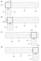
- 7A to 7D are diagrams schematically showing search processing according to the embodiment.
- FIG. 8 is a flowchart showing extraction processing of a pixel block corresponding to a target pixel block according to the embodiment.
- FIG. 9(a) is a graph schematically showing the correlation value of each search position calculated in the first process according to the embodiment.
- FIG. 9(b) is a graph schematically showing the correlation value of each search position calculated in the second process according to the embodiment.
- FIG. 10(a) is a flowchart showing processing for calculating a distance to an object according to the embodiment.
- FIG. 10(b) is a diagram schematically showing a method of obtaining a pixel shift amount according to the embodiment.
- 11(a) and 11(b) are diagrams schematically showing examples of usage patterns of the stereo camera system, respectively, according to the embodiment.
- FIG. 12 is a flowchart showing extraction processing of a pixel block corresponding to a target pixel block according to Modification 1.
- FIG. 13A is a graph schematically showing the correlation value of each search position calculated in the first process according to Modification 1.
- FIG. FIG. 13B is a graph schematically showing the correlation value of each search position calculated in the second process according to Modification 1.
- FIG. FIG. 14 is a flowchart showing extraction processing of a pixel block corresponding to a target pixel block according to Modification 2.
- FIG. 15A is a graph schematically showing the correlation value of each search position calculated in the first process according to Modification 2.
- FIG. 15B is a graph schematically showing the correlation value of each search position calculated in the second process according to Modification 2.
- FIG. 16A is a diagram showing a method of setting a target pixel block according to Modification 3.
- FIG. 16B is a diagram showing a method of setting a search area according to Modification 3.
- FIG. 17A is a diagram showing a method of setting a target pixel block according to Modification 3.
- FIG. FIG. 17B is a diagram showing a method of setting a search area according to Modification 3.
- FIGS. 18(a) to 18(c) are diagrams schematically showing the search processing for the search area according to Modification 3.
- FIG. FIG. 19 is a flow chart showing a matching pixel block extraction process according to Modification 3. As shown in FIG.
- each figure is labeled with mutually orthogonal X, Y, and Z axes.
- the X-axis direction is the separation direction of the first imaging section and the second imaging section, and the Z-axis positive direction is the imaging direction of each imaging section.
- FIG. 1 is a diagram showing the configuration of the stereo camera system 1.
- the stereo camera system 1 includes a first imaging section 10, a second imaging section 20, and an image processing device 30.
- the first imaging unit 10 includes an imaging lens 11 and an imaging device 12 .
- the imaging lens 11 collects light from the imaging area onto the light receiving surface of the imaging device 12 .
- the imaging device 12 is a CMOS image sensor.
- the imaging element 12 may be a CCD.
- the second imaging section 20 has the same configuration as the first imaging section 10.
- the second imaging section 20 includes an imaging lens 21 and an imaging device 22 .
- the imaging lens 21 collects light from the imaging area onto the light receiving surface of the imaging device 22 .
- the imaging device 22 is a CMOS image sensor.
- the imaging element 22 may be a CCD.
- the first imaging section 10 and the second imaging section 20 are arranged at the same position in the Y-axis direction and the Z-axis direction, and are separated from each other in the X-axis direction.
- the imaging direction of the first imaging unit 10 and the second imaging unit 20 is the Z-axis positive direction. That is, the optical axes of the imaging lenses 11 and 21 are parallel to the Z-axis.
- the imaging area of the first imaging section 10 and the imaging area of the second imaging section 20 overlap each other.
- the image processing device 30 has a circuit board on which a semiconductor integrated circuit made up of an FPGA (Field Programmable Gate Array) is mounted.
- An imaging processing unit 31, an input signal storage unit 32, a measurement unit 33, an output signal storage unit 34, and a communication interface 35 are arranged in the semiconductor integrated circuit. Each of these units executes processing according to the logic circuit design set in the FPGA.
- the image processing device 30 may include other semiconductor integrated circuits such as DSP (Digital Signal Processor), GPU (Graphics Processing Unit) and ASIC (Application Specific Integrated Circuit), or may include a microcomputer. .
- the imaging processing unit 31 controls the imaging elements 12 and 22, and performs brightness correction, camera calibration, and the like on the pixel signal of each pixel on the imaging element 12 and the pixel signal of each pixel on the imaging element 22.
- the processing is performed in order, and the stereo image signal after processing is stored in the input signal storage unit 32 .
- the first image output from the first imaging unit 10 and processed by the imaging processing unit 31 and the second image output from the second imaging unit 20 and processed by the imaging processing unit 31 are stored in the input signal storage unit 32. are stored respectively.
- the measurement unit 33 includes two processing circuits that respectively execute a first process and a second process, which will be described later.
- the measurement unit 33 acquires the distance to the object projected onto each pixel block on the first image by performing comparison processing on the first image and the second image and searching for stereo corresponding points.
- the acquired distance information is stored in the output signal storage unit 34 in association with each pixel block.
- the measurement unit 33 sets a pixel block for which a distance is to be obtained (hereinafter referred to as a “target pixel block”) on the first image, and sets a pixel block corresponding to this target pixel block, that is, a target pixel block. (hereinafter referred to as "matching pixel block”) is searched in a search range defined on the second image. Then, the measurement unit 33 determines the distance between the pixel block (hereinafter referred to as the “reference pixel block”) located at the same position as the target pixel block on the second image and the matching pixel block extracted from the second image by the above search. A process of acquiring the pixel displacement amount and calculating the distance to the object at the position of the target pixel block from the acquired pixel displacement amount is performed. The distance signal stored in the output signal storage unit 34 is transmitted to the external device via the communication interface 35 .
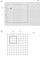
- FIG. 2(a) and (b) are diagrams schematically showing a method of setting the pixel blocks 102 for the first image 100.
- FIG. FIG. 2(a) shows a method of setting pixel blocks 102 for the entire first image 100
- FIG. 2(b) shows an enlarged partial area of the first image 100.
- the first image 100 is divided into a plurality of pixel blocks 102 each including a predetermined number of pixel regions 101.
- FIG. A pixel region 101 is a region corresponding to one pixel on the image sensor 12 . That is, the pixel area 101 is the minimum unit of the first image 100 .
- one pixel block 102 is composed of nine pixel regions 101 arranged in three rows and three columns. However, the number of pixel regions 101 included in one pixel block 102 is not limited to this.
- FIG. 3(a) is a diagram schematically showing a state in which a target pixel block TB1 is set on the first image 100
- FIG. 3(b) shows a search for the target pixel block in FIG. 3(a).
- FIG. 10 is a diagram schematically showing a search range R0 set on the second image 200 for the purpose of FIG.
- Pixel block 202 includes the same number of pixel regions as pixel block 102 described above.
- the target pixel block TB1 is the pixel block 102 to be processed among the pixel blocks 102 included in the detection area A1.
- the reference pixel block TB2 is a pixel block 202 on the second image 200 located at the same position as the target pixel block TB1.
- the measurement unit 33 reads the first image 100 and the second image 200 captured at the same timing from the input signal storage unit 32 and processes them.
- the measurement unit 33 identifies the reference pixel block TB2 located at the same position as the target pixel block TB1 on the second image 200.
- the measuring unit 33 sets the position of the identified reference pixel block TB2 to the reference position P0 of the search range R0, and the range extending from the reference position P0 in the separation direction of the first imaging unit 10 and the second imaging unit 20 is set as the search range R0.
- the direction in which the search range R0 extends is set in the direction in which the pixel block (matching pixel block MB2) corresponding to the target pixel block TB1 on the second image 200 deviates from the reference position P0 due to parallax.
- the search range R0 is set by 12 pixel blocks 202 arranged in the right direction (the direction corresponding to the X-axis direction in FIG. 1) from the reference position P0.
- the number of pixel blocks 202 included in the search range R0 is not limited to this.
- the starting point of the search range R0 is not limited to the reference pixel block TB2.
- the starting point of the search range R0 may be set at a position shifted to the right by several blocks from the reference pixel block TB2.
- the measuring unit 33 searches for a pixel block (matching pixel block MB2) corresponding to the target pixel block TB1 in the search range R0 thus set.
- the measuring unit 33 performs a plurality of search processes in parallel on a plurality of ranges obtained by dividing the search range R0.
- the search range R0 is divided into two ranges, the first half and the latter half, and the first process and the second process are executed in parallel on these two ranges.
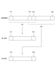
- FIG. 4 is a diagram showing how to set the search start position and search end position for the first process and the second process.
- the search start position ST1 and the search end position EN1 of the first process and the search start position ST2 and the search end position EN2 of the second process are set so that the search range R0 is divided into the first half and the second half.
- the search range is set to R0.
- the search range R0 is divided into a first search range R01 and a second search range R02.
- FIG. 5 is a diagram showing another method of setting the search start position and search end position for the first process and the second process.
- the first search range R01 and the second search range R02 partially overlap.
- two pixel blocks at the end of the first search range R01 and two pixel blocks at the beginning of the second search range overlap. Therefore, the first search range R01 and the second search range R02 are longer by one pixel block than in the case of FIG.
- the number of pixel blocks in which the first search range R01 and the second search range R02 overlap is not limited to this.
- FIG. 6 is a flowchart showing search processing for the matching pixel block MB2.
- FIG. 6 shows processing for the first image 100 and the second image 200 acquired at the same timing.
- the measurement unit 33 sets one of the pixel blocks 102 included in the detection area A1 on the first image 100 as the target pixel block TB1 (S101). For example, the pixel block 102 in the upper left corner of the detection area A1 in FIG. 3A is set as the target pixel block TB1.
- the measurement unit 33 sets the search range R0 of the target pixel block TB1 on the second image 200 by the method described above (S102). Then, the measurement unit 33 executes the above-described first processing (S103 to S107) and second processing (S108 to S112) in parallel on the set search range R0.
- the measuring unit 33 sets the search start position ST1 and the search end position EN1 by the method shown in FIG. 4 or 5, and starts the first process (S103).
- the measuring unit 33 sets a search position within the first search range R01 defined by the search start position ST1 and the search end position EN1 (S104), and the pixel block at this search position and the target pixel block A correlation value with TB1 is calculated (S105).
- the measurement unit 33 compares the correlation value calculated this time with the minimum value of the correlation values calculated so far, and if the correlation value calculated this time is smaller than the minimum value of the correlation values calculated so far, The correlation value is set to the minimum correlation value (S106).
- the measurement unit 33 executes the above processing for all search positions that can be set on the first search range R01 (S107).
- the measuring unit 33 sets the search start position ST1 of the first search range R01 as the search position (FIG. 6: S104).
- the measuring unit 33 sets a reference pixel block RB2 having the same size as the target pixel block TB1 at this search position, and calculates a correlation value between the target pixel block TB1 and the reference pixel block RB2 ( FIG. 6 : S105). .
- the correlation value is obtained, for example, by calculating the difference in pixel value (luminance) between the pixel regions 101 and 201 corresponding to each other in the target pixel block TB1 and the reference pixel block RB2, and calculating the absolute value of each calculated difference. It is obtained as an integrated value (SAD). Alternatively, the correlation value may be acquired as a value (SSD) obtained by accumulating all the values obtained by squaring the differences.
- the method of calculating the correlation value is not limited to the above, and other calculation methods may be used as long as they serve as an index of the correlation between the target pixel block TB1 and the reference pixel block RB2.
- the measurement unit 33 sets the current correlation value to the minimum correlation value ( FIG. 6 : S106). In the case of FIG. 7A, since the correlation value is calculated for the first time, the calculated correlation value is set to the minimum correlation value.
- the measurement unit 33 sets the next search position as shown in FIG. 7(b) (FIG. 6: S104). Specifically, the measuring unit 33 sets the current search position to a position obtained by shifting the previous search position by one pixel toward the terminal end of the first search range R01. Then, the measurement unit 33 calculates the correlation value between the reference pixel block RB2 at the current search position and the target pixel block TB1 by the same processing as described above ( FIG. 6 : S105). If it is smaller than the minimum value of the correlation values up to, the current correlation value is set to the minimum correlation value (FIG. 6: S106). In this case, the measurement unit 33 sets the current search position to the search position where the minimum correlation value is obtained.
- the measurement unit 33 repeats the same process while shifting the search position by one pixel toward the terminal end.
- FIG. 7(c) shows a state in which the reference pixel block RB2 is set at the search position immediately before the last search position in the first search range R01
- FIG. A state in which the reference pixel block RB2 is set at the final search position is shown.
- the second process in steps S108 to S112 is also performed in the same manner as the first process.
- the measuring unit 33 performs the same processes as in FIGS. 7A to 7D on the second search range R02 set for the second process.
- the measuring unit 33 acquires the search position with the minimum correlation value and its correlation value among the search positions sequentially set in the second process.
- the measurement unit 33 calculates the reference pixel block RB2 (matching pixel block MB2) is extracted (S113).
- FIG. 8 is a flow chart showing extraction processing of the matching pixel block MB2 corresponding to the target pixel block TB1 in step S113 of FIG.
- the measurement unit 33 compares the minimum correlation values obtained by the first process and the second process (S201). Then, the measuring unit 33 extracts the reference pixel block RB2 at the search position from which the smaller one of the two correlation values is obtained as the pixel block (matching pixel block MB2) corresponding to the target pixel block TB1. (S202).
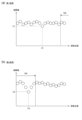
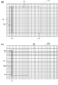
- FIG. 9(a) is a graph schematically showing the correlation value of each search position calculated in the first process.
- FIG. 9(b) is a graph schematically showing the correlation value of each search position calculated in the second process.
- the correlation value C1 at the search position P1 is the minimum value in the first process
- the correlation value C2 at the search position P2 is the minimum value in the second process.
- the correlation value C2 is smaller than the correlation value C1. Therefore, in this example, the reference pixel block RB2 at the search position P2 from which the correlation value C2 was obtained in the second process is extracted as the matching pixel block MB2 corresponding to the target pixel block TB1.
- the measurement unit 33 checks whether or not the processing has been completed for all the pixel blocks 102 within the detection area A1. Determine (S114). If the processing has not been completed for all pixel blocks 102 (S114: NO), the measurement unit 33 returns the processing to step S101, sets the next target pixel block TB1 from the pixel blocks within the detection area A1, The processing after step S102 is executed. As a result, the matching pixel block MB2 corresponding to the next target pixel block TB1 is extracted from the second image 200 (S113).
- the measurement unit 33 repeats the same process until the process is completed for all pixel blocks 102 within the detection area A1.
- matching pixel blocks MB2 corresponding to all pixel blocks 102 within the detection area A1 are extracted from the second image 200 (S113).
- S114: YES the measurement unit 33 ends the processing of FIG.
- the measurement unit 33 executes processing for calculating the distance to the object for each pixel block 102 within the detection area A1.
- FIG. 10(a) is a flowchart showing the process of calculating the distance to an object.
- the measurement unit 33 selects one pixel block 102 from among all the pixel blocks 102 (target pixel block TB1) included in the detection area A1, and extracts the pixel block 102 corresponding to this pixel block 102 by the processing in FIG.
- the pixel shift amount D1 of the matched pixel block MB2 is acquired (S301).
- the search position for the matching pixel block MB2 is the position P21
- the reference pixel block TB2 on the second image 200 at the same position as the selected pixel block 102 is A pixel shift amount D1 between (the pixel block at the search start position ST1) and the matching pixel block MB2 at the position P21 is acquired in step S301.
- the measurement unit 33 calculates the distance from the pixel shift amount D1 and the separation distance between the first imaging unit 10 and the second imaging unit 20 by triangulation.
- the distance calculated by the measurement unit 33 is stored in the output signal storage unit 34 as the distance to the object in the direction corresponding to the selected pixel block (S302).
- the measurement unit 33 repeats the same processing for all pixel blocks 102 (target pixel block TB1) included in the detection area A1 (S303). In this way, when the distances are obtained for all the pixel blocks 102 (target pixel block TB1) included in the detection area A1 (S303: YES), the distances stored in the output signal storage unit 34 are transmitted via the communication interface 35. , is sent to the external device (S304).
- the measurement unit 33 finishes processing the first image 100 and the second image 200 acquired at the same timing.
- the measurement unit 33 sequentially processes the first image 100 and the second image 200 acquired at subsequent timings, and the distances acquired for all the pixel blocks 102 included in the detection area A1 are transmitted via the communication interface 35. and sent to the external device.
- FIG. 10(a) may be performed between steps S113 and S114 of FIG. That is, when the matching pixel block MB2 is extracted in step S113, the pixel deviation amount D1 between this matching pixel block MB2 and the reference pixel block TB2 set in the extraction of this matching pixel block MB2 is acquired, and this pixel deviation is A distance based on the quantity D1 may be calculated. In this case, the distances for all the target pixel blocks TB1 are obtained by completing the processing in FIG.
- the output signal may be stored in the output signal storage unit 34 as a parallax signal instead of the distance, and transmitted to the external device via the communication interface 35 .
- the external device performs a process of converting the received parallax signal into a distance signal.
- the signal stored in the output signal storage unit 34 and transmitted to the external device may be any signal that can acquire the distance to the object to be imaged.
- FIGS. 11(a) and 11(b) are diagrams schematically showing examples of usage patterns of the stereo camera system 1.
- FIG. 11(a) and 11(b) are diagrams schematically showing examples of usage patterns of the stereo camera system 1.
- the stereo camera system 1 is installed near the grasping portion 2a of the robot arm 2.
- a robot arm 2 places an article 4 in a container 3 on a belt conveyor 5 .
- the stereo camera system 1 transmits the distances obtained for all target pixel blocks TB1 through the above process to the controller (external device) on the robot arm 2 side in step S304 of FIG. 10(a).
- the controller on the robot arm 2 side determines the position and distance of the container 3 based on the received distance of each target pixel block TB1 and controls the robot arm 2 to place the article 4 on the container 3 . Thereby, the robot arm 2 can smoothly place the article 4 on the container 3 as shown in FIG. 11(b).
- the search range R0 is divided into a plurality of ranges (first search range R01, second search range R02), and a plurality of search processes (first 1 process and second process) are executed.
- first search range R01 the search range
- second search range R02 the search range R0
- search processes first 1 process and second process
- the measuring unit 33 performs a plurality of search processes on the same search range R0, that is, the first process (S103 to S107) and the second process (S108 to S112) in parallel. .
- the time required to search the search range R0 can be significantly shortened compared to the case where the search is continuously performed over the entire search range R0. Therefore, the search for the target pixel block TB1 can be performed at a higher speed.
- the measurement unit 33 determines the reference pixel block having the highest degree of correlation with the target pixel block TB1 based on the processing results of a plurality of search processes (the first process and the second process).
- RB2 reference pixel block RB2 with the minimum correlation value
- S202 target pixel block TB1
- the reference pixel block RB2 for which the minimum correlation value (highest degree of correlation) is obtained is extracted as the pixel block (matching pixel block MB2) corresponding to the target pixel block TB1.
- the reference pixel block RB2 whose degree of correlation with the target pixel block TB1 does not exceed the predetermined threshold is excluded from the extraction targets.
- FIG. 12 is a flow chart showing extraction processing of the matching pixel block MB2 corresponding to the target pixel block TB1 according to Modification 1. As shown in FIG. This process is executed in step S113 of FIG.
- the measurement unit 33 determines the minimum correlation value obtained in the first processing of steps S103 to S107 in FIG.
- the reference pixel block RB2 for which the value has been acquired (the reference pixel block RB2 whose degree of correlation does not exceed the threshold value) is excluded from extraction targets (S401). Then, the measurement unit 33 extracts the reference pixel block RB2 from which the correlation values remaining without being excluded in step S401 are acquired as a pixel block (matching pixel block MB2) corresponding to the target pixel block (S402).
- FIG. 13(a) is a graph schematically showing the correlation value of each search position calculated in the first process according to Modification 1.
- FIG. 13B is a graph schematically showing the correlation value of each search position calculated in the second process according to Modification 1.
- FIG. 13(a) is a graph schematically showing the correlation value of each search position calculated in the first process according to Modification 1.
- FIG. 13B is a graph schematically showing the correlation value of each search position calculated in the second process according to Modification 1.
- the correlation value C1 at the search position P1 is the minimum value in the first process
- the correlation value C2 at the search position P2 is the minimum value in the second process.
- the correlation value C1 is greater than or equal to the threshold Th0
- the correlation value C2 is less than the threshold Th0. Therefore, in this example, the reference pixel block RB2 at the search position P1 from which the correlation value C1 was obtained in the first process is excluded from the extraction target, and the reference pixel block RB2 at the search position P2 from which the correlation value C2 was obtained in the second process is excluded.
- RB2 is extracted as the matching pixel block MB2 corresponding to the target pixel block TB1.
- the threshold Th0 is set to a value that allows the reference pixel block RB2 (matching pixel block MB2) corresponding to the target pixel block TB1 to be properly acquired in the measurement distance range by the processing of FIG. That is, when the threshold Th0 is too high (when the degree of correlation at the threshold Th0 is too low), both of the correlation values C1 and C2 obtained by the first process and the second process are less than the threshold Th0. 2, the reference pixel block RB2 (matching pixel block MB2) corresponding to the target pixel block TB1 cannot be obtained properly.
- both the correlation values C1 and C2 obtained by the first process and the second process are equal to or greater than the threshold Th0. 2, the reference pixel block RB2 (matching pixel block MB2) corresponding to the target pixel block TB1 cannot be obtained properly.
- the threshold value Th0 is obtained by the processing of FIG. 12, and only one of the correlation values C1 and C2 obtained by the first processing and the second processing remains without being excluded, and the remaining correlation value is obtained.
- the reference pixel block RB2 is set to be a reference pixel block (matching pixel block MB2) at an appropriate pixel shift position according to the distance to the object. This setting is, for example, whether or not the distance of each target pixel block TB1 (matching pixel block MB2) can be properly acquired while changing the threshold value Th0 with an object placed at a predetermined distance position within the measurement distance range. This can be done by checking
- Th0 the degree of correlation does not exceed the predetermined threshold pixel block
- step S401 of FIG. 12 by any chance, the correlation values obtained by the first process and the second process are all less than the threshold, and none of the reference pixel blocks RB2 from which these correlation values are obtained are excluded. In this case, the reference pixel block RB2 from which the smaller one of these correlation values is obtained may be extracted as the reference pixel block RB2 corresponding to the target pixel block TB1.
- step S401 of FIG. 12 if the correlation values obtained by the first process and the second process are all equal to or greater than the threshold value, and the reference pixel block RB2 for which these correlation values are obtained are excluded. , the reference pixel block RB2 corresponding to the target pixel block TB1 may be processed as if it could not be extracted. It may be extracted as a reference pixel block RB2.
- the reference pixel block RB2 for which the minimum correlation value (highest degree of correlation) is obtained is extracted as the pixel block (matching pixel block MB2) corresponding to the target pixel block TB1.
- the measurement unit 33 acquires information about the distance to the object to be imaged from an external device via the communication interface 35, and extracts the matching pixel block MB2 based on the acquired information. Select the processing result to be targeted.
- FIG. 14 is a flowchart showing extraction processing of a pixel block corresponding to the target pixel block TB1 according to Modification 2. As shown in FIG. This process is executed in step S113 of FIG.
- the measurement unit 33 acquires the control position information (three-dimensional position, rotation angle, rotation radius, etc.) of the grasping unit 2a of the robot arm 2 from the control device on the robot arm 2 side via the communication interface 35 (S501). .
- the measurement unit 33 calculates an estimated value of the distance to the container 3 based on the acquired control position information (S502), and a predetermined range of distances before and after the calculated estimated value (range of fluctuation width that can be estimated ) is set as the extraction range W0 of the search position (S503).
- the measuring unit 33 selects the search position included in the extraction range W0 from among the search positions with the minimum correlation values obtained in the first process and the second process (S504), and selects the selected search position. is extracted as a matching pixel block MB2 (S505).
- FIG. 15(a) is a graph schematically showing the correlation value of each search position calculated in the first process according to modification example 2.
- FIG. 15B is a graph schematically showing the correlation value of each search position calculated in the second process according to Modification 2.
- FIG. 15(a) is a graph schematically showing the correlation value of each search position calculated in the first process according to modification example 2.
- FIG. 15B is a graph schematically showing the correlation value of each search position calculated in the second process according to Modification 2.
- the correlation value C1 at the search position P1 is the minimum value in the first process
- the correlation value C2 at the search position P2 is the minimum value in the second process.
- the search position P1 for the correlation value C1 is not included in the extraction range W0
- the search position P2 for the correlation value C2 is included in the extraction range W0. Therefore, in this example, the reference pixel block RB2 at the search position P2 from which the correlation value C2 was obtained in the second process is extracted as the matching pixel block MB2 corresponding to the target pixel block TB1.
- the extraction range W0 of the search position is set based on the information about the distance to the object to be imaged (the control position information of the grip part 2a), and is obtained by the first process and the second process.
- the search positions included in the extraction range W0 are selected as the search positions for the matching pixel block MB2. can be extracted.
- step S504 of FIG. 14 if the search positions obtained by the first process and the second process are both included in the extraction range W0, the search position with the smaller correlation value , is extracted as the search position of the reference pixel block RB2 corresponding to the target pixel block TB1.
- step S504 of FIG. 14 if none of the search positions acquired by the first process and the second process are included in the extraction range W0, the reference pixel block RB2 corresponding to the target pixel block TB1 could not be extracted, or one of these search positions with a smaller correlation value may be extracted as the search position of the reference pixel block RB2 corresponding to the target pixel block TB1.
- the control position information of the gripping unit 2a is acquired as information about the distance to the object to be imaged (S501), and based on this information, the estimated value of the distance to the object to be imaged is obtained by the measurement unit. 33 (S502), the control device on the robot arm 2 side calculates an estimated value of the distance from the control position of the grip part 2a to the object to be imaged. may be transmitted to the measurement unit 33 as information related to the distance of . In this case, the measurement unit 33 may perform the processes after step S503 in FIG. 14 .
- the information about the distance to the object to be imaged acquired by the measurement unit 33 may be other information. For example, the extraction range W0 in step S503 of FIG.
- the measurement unit 33 may acquire it.
- ⁇ Modification 3> In the above embodiment, as shown in FIG. 6, a plurality of search processes (first process, second process) are performed in parallel on the same search range R0. On the other hand, in Modification 3, a plurality of search processes (first process, second process) for the same search range are performed at different timings, and the plurality of search processes (first process, second process) are performed respectively. It is done in parallel for multiple search ranges.
- FIG. 16(a) is a diagram showing a method for setting the target pixel block TB1 according to Modification 3.
- FIG. 16B is a diagram showing a method of setting the search area A2 according to Modification 3. As shown in FIG.
- FIG. 16(a) shows a state in which the target pixel block TB1 is set for the leading column L11.
- the pixel block of column L21 on the second image 200 which is located at the same position as column L11, is set as the reference pixel block TB2.
- search ranges R1, R2, . be done.
- Rk of the column L21 set in this way are searched for the matching pixel block MB2, and based on the searched matching pixel block MB2, each of the target pixel blocks TB1 of the column L11. is obtained. Then, when the processing for columns L11 and L21 is completed, the target pixel block TB1 is set for the next column L12 as shown in FIG. 17(a), and as shown in FIG. The pixel block of column L22 located at the position is set as the reference pixel block TB2. Then, in the same manner as described above, search ranges R1, R2, . Configured.
- a similar process is similarly executed up to the last row L1n of the detection area A1. As a result, search and distance acquisition are performed for all pixel blocks included in the detection area A1.
- a plurality of search processes (first process, second process) for the same search range are performed at mutually different timings, and a plurality of search processes (first process) are performed.
- second processing are performed in parallel for each of the plurality of search ranges.
- FIGS. 18(a) to 18(c) are diagrams schematically showing search processing for the search area A2 according to Modification 3.
- FIG. in FIGS. 18A to 18C hatching indicates the range in which search processing is performed.
- one search range is divided into the first half and the second half.
- the first process is performed on the first half of the search range
- the second process is performed on the second half of the search range. Then, while the first process is performed on the first half of one search range, the second process is performed in parallel on the latter half of the search range that is one search range below this search range.
- the measurement unit 33 concurrently executes the first process for the uppermost search range R1 and the second process for the second search range R2 from the top.
- the measurement unit 33 performs the first process on the second search range R2 from the top and the second process on the third search range R3 from the top, as shown in FIG. 18(b). , run in parallel.
- the measurement unit 33 sequentially performs the first process and the second process in parallel while shifting the search range to be processed by one.
- the measurement unit 33 concurrently executes the second process on the uppermost search range R1 as shown in FIG. 18(c). do. In this way, the measurement unit 33 completes the search processing for one search area A2.
- the minimum correlation value and its search position by the first process and the minimum correlation value and its search position by the second process are obtained for each search range. Therefore, the matching pixel block MB2 in each search range can be extracted by comparing the two obtained correlation values in the same manner as in FIGS. 9A and 9B.
- the methods of modified examples 1 and 2 may be used as the method of extracting the suitable pixel block MB2.
- one search range is divided into the first half and the latter half, but as shown in FIG. The range may partially overlap. Also, in FIGS. 18A to 18C, the search range in which the first process and the second process are performed is shifted by one, but the search range in which the first process and the second process are performed is two or more. may be shifted.
- FIG. 19 is a flowchart showing extraction processing of the matching pixel block MB2 according to Modification 3.
- FIG. 19 is a flowchart showing extraction processing of the matching pixel block MB2 according to Modification 3.
- the measurement unit 33 While performing the processing steps for one row shown in FIGS. 18(a) to 18(c), the measurement unit 33 stores the minimum correlation value and the search position obtained by the first processing and the second processing in the search range. are stored in the output signal storage unit 34 in association with .
- the method of acquiring the minimum correlation value and its search position in the first and second processes is the same as the method shown in FIGS. 7(a) to (d).
- the measurement unit 33 reads out the processing results of the first processing and the second processing thus stored for each search range, and executes the processing in FIG. 19 .
- the measuring unit 33 After completing the processing for one column (S601: YES), the measuring unit 33 sets the variable N to 1 (S602), and obtains the N-th search range from the top by the first processing and the second processing. The minimum correlation value obtained is read out from the output signal storage unit 34 (S603). Then, the measurement unit 33 extracts the matching pixel block MB2 corresponding to the N-th target pixel block TB1 from the top of this column based on the correlation value read out from the output signal storage unit 34 (S604). That is, as in the above-described embodiment, the measurement unit 33 stores the pixel block at the search position corresponding to the smaller correlation value among the correlation values of the first process and the second process read from the output signal storage unit 34 as matching pixels. Extract as block MB2.
- the measuring unit 33 determines whether the variable N has reached the maximum value Nmax of the target pixel block TB1 included in one column. is determined (S605). If the determination in step S605 is NO, the measurement unit 33 adds 1 to the variable N (S606) and returns the process to step S603. As a result, the matching pixel block MB2 corresponding to the next target pixel block TB1 is extracted (S603, S604). The measurement unit 33 repeats the same processing until the processing for the last target pixel block in this column is completed (S605: NO).
- the measurement unit 33 finishes processing for this column.
- matching pixel blocks MB2 are extracted for all target pixel blocks TB1 included in the column to be processed.
- the measurement unit 33 executes the processing shown in FIG. 19 for the next row of the detection area A1.
- the matching pixel block MB2 is extracted for all the target pixel blocks TB1 included in the detection area A1.
- the measurement unit 33 performs the process of FIG. 10(a). As a result, distances to all target pixel blocks TB1 included in the detection area A1 are calculated, and the calculated distances of each target pixel block TB1 are transmitted to the external device.
- a plurality of search processes (the first process and the second process) are performed in parallel. , the time required to search the search range can be shortened. Therefore, the search for the target pixel block TB1 can be performed at high speed.
- the minimum correlation value and its search position obtained by the first process and the second process are temporarily stored in the output signal storage unit 34 in association with the search range.
- a buffer memory or the like may be provided exclusively for the storage of .
- each matching pixel block MB2 is output from either the first process or the second process.
- the distance signal output from either the first process or the second process may be stored in the output signal storage unit 34 without comparing the correlation values obtained. Thereby, the distance signal can be stored in association with the target pixel block, and the processing is reduced.
- one search range is divided into two, and two search processes (first process and second process) are applied to each of the two divided ranges,
- One search range may be divided into three or more, and three or more search processes may be applied to each of the three or more divided ranges.
- one search range is divided into ranges containing the same number of pixel blocks, but one search range is divided into ranges containing different numbers of pixel blocks. may be partitioned.
- the length of the search range R0 is not limited to the length shown in the above embodiment, and may be set according to the measurement distance range.
- each time a correlation value is acquired (S105, S110), the acquired correlation value is compared with the minimum correlation value acquired so far, and the first process and the second process are compared.
- the minimum correlation value is extracted (in S106 and S111), the method of obtaining the minimum correlation value is not limited to this.
- all the correlation values obtained in the first process and the second process are stored in the output signal storage unit 34 or the like, the minimum correlation value is extracted from among them, and the pixel block of the extracted correlation value is processed as a target. It may be extracted as a matching pixel block MB2 corresponding to the pixel block TB1.
- the usage pattern of the stereo camera system 1 is not limited to the usage pattern shown in FIGS. 11(a) and 11(b).
- the configuration of the stereo camera system 1 is not limited to the configuration shown in the above embodiment. may
- first imaging unit 20 second imaging unit 30 image processing device 33 measurement unit R0, R1 to Rk search range R01 first search range R02 second search range TB1 target pixel block TB2 reference pixel block MB2 matching pixel block (Pixel block corresponding to target pixel block)
Landscapes
- Engineering & Computer Science (AREA)
- Computer Vision & Pattern Recognition (AREA)
- Physics & Mathematics (AREA)
- General Physics & Mathematics (AREA)
- Theoretical Computer Science (AREA)
- Multimedia (AREA)
- Signal Processing (AREA)
- Human Computer Interaction (AREA)
- Measurement Of Optical Distance (AREA)
- Endoscopes (AREA)
Priority Applications (3)
| Application Number | Priority Date | Filing Date | Title |
|---|---|---|---|
| JP2023573931A JPWO2023136050A1 (https=) | 2022-01-14 | 2022-12-19 | |
| CN202280088328.6A CN118511538A (zh) | 2022-01-14 | 2022-12-19 | 图像处理装置以及图像处理方法 |
| US18/768,259 US20240362809A1 (en) | 2022-01-14 | 2024-07-10 | Image processing device and image processing method |
Applications Claiming Priority (2)
| Application Number | Priority Date | Filing Date | Title |
|---|---|---|---|
| JP2022004116 | 2022-01-14 | ||
| JP2022-004116 | 2022-01-14 |
Related Child Applications (1)
| Application Number | Title | Priority Date | Filing Date |
|---|---|---|---|
| US18/768,259 Continuation US20240362809A1 (en) | 2022-01-14 | 2024-07-10 | Image processing device and image processing method |
Publications (1)
| Publication Number | Publication Date |
|---|---|
| WO2023136050A1 true WO2023136050A1 (ja) | 2023-07-20 |
Family
ID=87278927
Family Applications (1)
| Application Number | Title | Priority Date | Filing Date |
|---|---|---|---|
| PCT/JP2022/046714 Ceased WO2023136050A1 (ja) | 2022-01-14 | 2022-12-19 | 画像処理装置および画像処理方法 |
Country Status (4)
| Country | Link |
|---|---|
| US (1) | US20240362809A1 (https=) |
| JP (1) | JPWO2023136050A1 (https=) |
| CN (1) | CN118511538A (https=) |
| WO (1) | WO2023136050A1 (https=) |
Citations (4)
| Publication number | Priority date | Publication date | Assignee | Title |
|---|---|---|---|---|
| JP2008309637A (ja) * | 2007-06-14 | 2008-12-25 | Konica Minolta Holdings Inc | 障害物計測方法、障害物計測装置及び障害物計測システム |
| JP2012212428A (ja) * | 2011-03-23 | 2012-11-01 | Sharp Corp | 視差算出装置、距離算出装置及び視差算出方法 |
| JP2013242854A (ja) * | 2012-04-17 | 2013-12-05 | Panasonic Corp | 視差算出装置及び視差算出方法 |
| JP2017045283A (ja) * | 2015-08-26 | 2017-03-02 | 株式会社ソニー・インタラクティブエンタテインメント | 情報処理装置および情報処理方法 |
Family Cites Families (2)
| Publication number | Priority date | Publication date | Assignee | Title |
|---|---|---|---|---|
| JP6245885B2 (ja) * | 2013-08-02 | 2017-12-13 | キヤノン株式会社 | 撮像装置およびその制御方法 |
| WO2017163928A1 (ja) * | 2016-03-24 | 2017-09-28 | ソニー株式会社 | 画像処理装置および方法 |
-
2022
- 2022-12-19 JP JP2023573931A patent/JPWO2023136050A1/ja active Pending
- 2022-12-19 CN CN202280088328.6A patent/CN118511538A/zh active Pending
- 2022-12-19 WO PCT/JP2022/046714 patent/WO2023136050A1/ja not_active Ceased
-
2024
- 2024-07-10 US US18/768,259 patent/US20240362809A1/en active Pending
Patent Citations (4)
| Publication number | Priority date | Publication date | Assignee | Title |
|---|---|---|---|---|
| JP2008309637A (ja) * | 2007-06-14 | 2008-12-25 | Konica Minolta Holdings Inc | 障害物計測方法、障害物計測装置及び障害物計測システム |
| JP2012212428A (ja) * | 2011-03-23 | 2012-11-01 | Sharp Corp | 視差算出装置、距離算出装置及び視差算出方法 |
| JP2013242854A (ja) * | 2012-04-17 | 2013-12-05 | Panasonic Corp | 視差算出装置及び視差算出方法 |
| JP2017045283A (ja) * | 2015-08-26 | 2017-03-02 | 株式会社ソニー・インタラクティブエンタテインメント | 情報処理装置および情報処理方法 |
Also Published As
| Publication number | Publication date |
|---|---|
| JPWO2023136050A1 (https=) | 2023-07-20 |
| US20240362809A1 (en) | 2024-10-31 |
| CN118511538A (zh) | 2024-08-16 |
Similar Documents
| Publication | Publication Date | Title |
|---|---|---|
| JP5293131B2 (ja) | 車両用複眼距離測定装置及び複眼距離測定方法 | |
| JP5365387B2 (ja) | 位置検出装置 | |
| JP6208419B2 (ja) | 算出装置、搬送ロボットシステム、及び算出方法 | |
| JP2008087074A (ja) | ワーク取り出し装置 | |
| WO2011132552A1 (ja) | 情報処理装置、プログラム、情報処理方法、および情報処理システム | |
| KR102316448B1 (ko) | 이미지 장치 및 그것의 뎁쓰 계산 방법 | |
| CN101990065A (zh) | 图像处理装置、图像拍摄装置、图像处理方法和程序 | |
| JP2004317245A (ja) | 距離検出装置、距離検出方法、及び距離検出プログラム | |
| US20190108648A1 (en) | Phase detection auto-focus-based positioning method and system thereof | |
| JP2017129788A5 (https=) | ||
| JP2019168479A (ja) | 制御装置、撮像装置、制御方法、プログラム、および、記憶媒体 | |
| US10726528B2 (en) | Image processing apparatus and image processing method for image picked up by two cameras | |
| WO2023136050A1 (ja) | 画像処理装置および画像処理方法 | |
| JP2008298589A (ja) | 位置検出装置及び位置検出方法 | |
| EP3640585B1 (en) | Stereo camera device | |
| US20230306566A1 (en) | Image processing apparatus, image processing method, and storage medium | |
| EP3647716A1 (en) | Imaging device | |
| JP4817552B2 (ja) | 位相差検出方法、位相差検出装置、測距装置および撮像装置 | |
| JP2015207862A (ja) | 撮像装置および撮像方法 | |
| JP2022024676A (ja) | 測距装置 | |
| WO2016047220A1 (ja) | 撮像装置及び撮像方法 | |
| JP6730029B2 (ja) | 画像処理装置、画像処理方法、画像処理プログラム、および撮像装置 | |
| JP4672470B2 (ja) | 赤外線撮像装置 | |
| JP2016076838A (ja) | 画像処理装置及び画像処理装置の制御方法 | |
| JP2018200268A (ja) | 画像認識装置 |
Legal Events
| Date | Code | Title | Description |
|---|---|---|---|
| 121 | Ep: the epo has been informed by wipo that ep was designated in this application |
Ref document number: 22920568 Country of ref document: EP Kind code of ref document: A1 |
|
| WWE | Wipo information: entry into national phase |
Ref document number: 202280088328.6 Country of ref document: CN |
|
| ENP | Entry into the national phase |
Ref document number: 2023573931 Country of ref document: JP Kind code of ref document: A |
|
| NENP | Non-entry into the national phase |
Ref country code: DE |
|
| 122 | Ep: pct application non-entry in european phase |
Ref document number: 22920568 Country of ref document: EP Kind code of ref document: A1 |