WO2023135717A1 - 3次元モデルを作成する装置、方法及びプログラム - Google Patents
3次元モデルを作成する装置、方法及びプログラム Download PDFInfo
- Publication number
- WO2023135717A1 WO2023135717A1 PCT/JP2022/001022 JP2022001022W WO2023135717A1 WO 2023135717 A1 WO2023135717 A1 WO 2023135717A1 JP 2022001022 W JP2022001022 W JP 2022001022W WO 2023135717 A1 WO2023135717 A1 WO 2023135717A1
- Authority
- WO
- WIPO (PCT)
- Prior art keywords
- dimensional model
- image
- point
- range
- point cloud
- Prior art date
- Legal status (The legal status is an assumption and is not a legal conclusion. Google has not performed a legal analysis and makes no representation as to the accuracy of the status listed.)
- Ceased
Links
Images






Classifications
-
- G—PHYSICS
- G06—COMPUTING OR CALCULATING; COUNTING
- G06T—IMAGE DATA PROCESSING OR GENERATION, IN GENERAL
- G06T17/00—Three-dimensional [3D] modelling for computer graphics
-
- G—PHYSICS
- G01—MEASURING; TESTING
- G01B—MEASURING LENGTH, THICKNESS OR SIMILAR LINEAR DIMENSIONS; MEASURING ANGLES; MEASURING AREAS; MEASURING IRREGULARITIES OF SURFACES OR CONTOURS
- G01B21/00—Measuring arrangements or details thereof, where the measuring technique is not covered by the other groups of this subclass, unspecified or not relevant
-
- G—PHYSICS
- G01—MEASURING; TESTING
- G01C—MEASURING DISTANCES, LEVELS OR BEARINGS; SURVEYING; NAVIGATION; GYROSCOPIC INSTRUMENTS; PHOTOGRAMMETRY OR VIDEOGRAMMETRY
- G01C15/00—Surveying instruments or accessories not provided for in groups G01C1/00 - G01C13/00
-
- G—PHYSICS
- G06—COMPUTING OR CALCULATING; COUNTING
- G06T—IMAGE DATA PROCESSING OR GENERATION, IN GENERAL
- G06T19/00—Manipulating three-dimensional [3D] models or images for computer graphics
- G06T19/20—Editing of three-dimensional [3D] images, e.g. changing shapes or colours, aligning objects or positioning parts
-
- G—PHYSICS
- G06—COMPUTING OR CALCULATING; COUNTING
- G06T—IMAGE DATA PROCESSING OR GENERATION, IN GENERAL
- G06T2210/00—Indexing scheme for image generation or computer graphics
- G06T2210/56—Particle system, point based geometry or rendering
-
- G—PHYSICS
- G06—COMPUTING OR CALCULATING; COUNTING
- G06T—IMAGE DATA PROCESSING OR GENERATION, IN GENERAL
- G06T2219/00—Indexing scheme for manipulating 3D models or images for computer graphics
- G06T2219/20—Indexing scheme for editing of 3D models
- G06T2219/2004—Aligning objects, relative positioning of parts
Definitions
- the present disclosure relates to technology for creating a 3D model from point cloud data representing 3D coordinates.
- Patent Literature 1 A technology has been developed to create a three-dimensional model of an outdoor structure using a three-dimensional laser scanner (Mobile Mapping System: MMS) mounted on a vehicle (see Patent Document 1, for example).
- MMS Mobile Mapping System
- Patent Document 1 A technology has been developed to create a three-dimensional model of an outdoor structure using a three-dimensional laser scanner (Mobile Mapping System: MMS) mounted on a vehicle (see Patent Document 1, for example).
- MMS Mobile Mapping System
- the points are interpolated up to a certain threshold for the distance between the point clouds to form a scan line. Can not do it. Therefore, in 3D modeling using a fixed 3D laser scanner, there is a problem that it is difficult to create a 3D model of an object with a small diameter, such as a cable near a utility pole.
- An object of the present disclosure is to enable the creation of a three-dimensional model even for an object in which the point-to-point distances are not evenly spaced and the point cloud is only partially present.
- the apparatus and methods of the present disclosure comprise: Create a 3D model of the object from point cloud data where each point represents a 3D coordinate, superimposing the three-dimensional model on an image in which the object of the three-dimensional model is captured; displaying a superimposed image generated by the superimposition; When the range of the object in the superimposed image is input, a three-dimensional model is created again using point cloud data in which points are located in the range of the superimposed image.
- a 3D model of an object can be created without depending on the distance between 3D points. Therefore, the present disclosure can enable the creation of a three-dimensional model even for an object in which the point-to-point distances are not evenly spaced and the point cloud is only partially present.
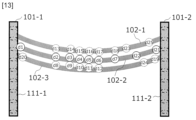
- An example of point cloud data is shown.
- An example of a three-dimensional model in which a structure is objectified is shown.
- 1 shows a system configuration example of the present disclosure
- 4 shows an example of a point cloud stored in a storage medium
- 4 shows an example of an image stored in a storage medium
- An example of the method of this embodiment is shown.
- An example of a three-dimensional model created in step S1 is shown.
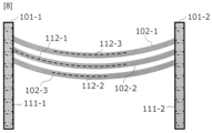
- An example of a superimposed image in which a three-dimensional model is superimposed on an image is shown.
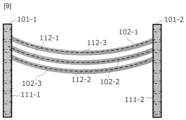
- An example of a three-dimensional model created in step S3 is shown.
- An example of inputting a range of objects is shown.
- a specific example of step S3 is shown.
- An example of a first method for comparing sizes of objects is shown.
- FIG. 3 shows an example of adding a point cloud that constitutes a three-dimensional model.
- An example of a three-dimensional model after correction is shown.
- An example of a second method for comparing sizes of objects is shown.
- An example of display of the size of an object is shown.
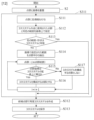
- a specific example of step S3 is shown.
- An example of a state in which the three-dimensional model is extended is shown.
- An example of setting end points of a three-dimensional model is shown.
- the present disclosure is an apparatus and method for creating a three-dimensional model of an object from point cloud data representing three-dimensional coordinates acquired by a three-dimensional laser scanner.
- FIG. 1 shows an example of point cloud data.
- the point cloud data is data in which the surface shape of an object such as a structure is represented by a set of points 91, and each point 91 represents the three-dimensional coordinates of the surface of the structure.
- a line 92 that connects points 91 of the 3D point cloud data
- a 3D model in which the structure is made into an object can be created.
- a three-dimensional utility pole model 111 and cable model 112 can be created.
- Fig. 3 shows a system configuration example of the present disclosure.
- the disclosed system comprises a fixed 3D laser scanner 1-1 for measuring an object 100, a camera 1-2 for imaging the object 100, and the device 5 of the present disclosure.
- the device 5 of the present disclosure includes an arithmetic processing unit 3 and a display unit 4 and may additionally include a storage medium 2 .
- the device 5 of the present disclosure can also be realized by a computer and a program, and the program can be recorded on a recording medium or provided through a network.
- the system of the present disclosure stores point cloud data acquired by the fixed 3D laser scanner 1-1 and images captured by the camera 1-2 in the storage medium 2.
- FIG. 4 shows an example of the point cloud stored in the storage medium 2.
- points d1 to d25 are stored between the measured point clouds dp1 and dp2 of the utility pole.
- FIG. 5 shows an example of an image saved in the storage medium 2.
- an image in which cables 102-1, 102-2, and 102-3 are stretched between utility poles 101-1 and 101-2 is stored.
- the camera 1-2 may be a camera mounted on the fixed 3D laser scanner 1-1, or may be prepared separately. Moreover, it is desirable that the camera 1-2 capture images at the same position, direction, and angle of view as the position, direction, and angle of view at which the fixed 3D laser scanner 1-1 acquires the point cloud. This makes it easy to superimpose the point cloud acquired by the fixed 3D laser scanner 1-1 and the image captured by the camera 1-2. However, since the point cloud of the present disclosure has three-dimensional coordinates, if there is three-dimensional position information of the fixed 3D laser scanner 1-1 and the camera 1-2, points to the image can be mapped based on the relative positions. Superposition of groups is possible.
- FIG. 6 shows an example of the method of this embodiment.
- the method according to this embodiment includes: A method for generating a three-dimensional model of an object from point cloud data acquired by a three-dimensional laser scanner 1-1, step S1 in which the arithmetic processing unit 3 creates a three-dimensional model of the object from the three-dimensional point cloud data; step S2 in which the arithmetic processing unit 3 superimposes the created three-dimensional model of the object on the image of the object; step S3 in which the arithmetic processing unit 3 corrects the three-dimensional model based on a comparison between the three-dimensional model and the superimposed image; have
- step S1 an object is extracted from the point cloud and a 3D model is created (DBSCAN).
- DBSCAN is one of the clustering methods, and is a method in which a group of points included in the condition that there are more than the number of points within a threshold value of a certain point is regarded as one cluster and made into a cluster.
- the objects are, for example, utility poles 101-1 and 101-2, or cables 102-1, 102-2 and 102-3. An example in which the objects are cables 102-1, 102-2, and 102-3 will be described below.
- FIG. 7 shows an example of the three-dimensional models 112-1, 112-2 and 112-3 created in step S1.
- the three-dimensional models 112-1, 112-2, and 112-3 are superimposed on the image as shown in FIG.
- step S3 by comparing the three-dimensional models 112-1, 112-2 and 112-3 with the cables 102-1, 102-2 and 102-3 in the image, a three-dimensional model as shown in FIG. Correct the models 112-1, 112-2, 112-3.
- the present disclosure can calculate facility information (sag, span length, etc.) from the corrected three-dimensional model.
- the superimposed image generated by superimposing is displayed on the display unit 4 in step S2. Then, when the user inputs the range of the object in the superimposed image like the cursors 103-1 and 103-2 shown in FIG. 10, the arithmetic processing section 3 executes step S3. In this step S3, the arithmetic processing unit 3 recreates the three-dimensional model using the point cloud data in which the points are located within the range of the superimposed image.
- the present disclosure it is possible to determine whether the 3D model is perfectly created by superimposing it on the image in step S2, and in step S3, the 3D model can be added as it is where it already exists, and if it is insufficient, it can be added. Accordingly, the present disclosure can determine the presence or absence of an object even if the object has only a part of the point cloud. Therefore, the present disclosure can construct a three-dimensional model of a fine line-shaped object such as a suspension line, an optical cable, an electric wire, or a horizontal branch line. Furthermore, the present disclosure can construct a three-dimensional model of a thin line-shaped object, so that the state of the thin line-shaped target facility can be detected.
- a fine line-shaped object such as a suspension line, an optical cable, an electric wire, or a horizontal branch line.
- the method of inputting the range of the object in step S2 is arbitrary.
- the cursor position on the screen may be used for input, or the range may be input by dragging.
- step S3 any method can be used to correct the three-dimensional model.
- a form of interpolating points to match the image and a form of interpolating the 3D model to match the image are exemplified.
- FIG. 11 shows a specific example of step S3.
- the arithmetic processing unit 3 superimposes the created three-dimensional model on the captured image (S2), and displays the superimposed image generated by the superimposition on the display unit 4.
- FIG. The arithmetic processing unit 3 acquires the range of the object in the superimposed image, and compares the three-dimensional model on the superimposed image with the size of the object in the image (S311). If the object in the image is larger, points are interpolated to create a three-dimensional model (S312), and the three-dimensional model is saved in the storage medium 2 (S313).
- step S312 the method for superimposing the image and the point cloud and comparing the size of the object is arbitrary, but the following can be exemplified.
- the first method is to superimpose a point group and an image, and compare the size of pixels of the same color specified in the superimposed image with the size of the three-dimensional model.
- Second method A method of comparing the size with the three-dimensional model by matching with facility information in a database prepared in advance.
- FIG. 12 shows an example of the first method.
- the first method is to determine how far the point cloud indicating the cable is, which is used to create the three-dimensional model of the cable.
- the arithmetic processing unit 3 superimposes the image (S2), assigns the color information of the cable to the point cloud (S111), and the same color pixels of the point cloud used for creating the 3D model are displayed on the image.
- a range indicating how far it extends is acquired (S112). If the color range/shape differs from the three-dimensional model (No in S113), the arithmetic processing unit 3 extracts the point group included in the specified range in S112 (S114 to S117), and creates the three-dimensional model again ( S312 and S313).
- step S111 after the superimposition, the point cloud and the image are associated with each other, and the color information of the image at the same position on the image is added to each point cloud.
- three-dimensional model 112-1 overlaps cable 102-2.
- point groups d1 to d6 forming the three-dimensional model 112-1 are associated with the cable 102-2, and color information of the cable 102-2 is added to the point groups d1 to d6.
- step S112 the user, like the cursors 103-1 and 103-2 shown in FIG. 10, determines how far the pixels of the same color as the point group d1 to d6 corresponding to the extracted three-dimensional model 112-1 spread on the image. manually select whether As a result, a range in which the same color as that of the cable 102-2 spreads on the image is specified, and from point groups d1 to d25 within that range, a threshold value specified in advance from the extension of the approximation line of the three-dimensional model A three-dimensional model is created again using the point group inside (S113 to S117, S312).
- the threshold is defined as, for example, when the direction in which the approximation line of the three-dimensional model 112-1 extends is the x-axis, the depth is the y-axis, and the height direction is the z-axis, the distance between each point is ⁇ x ⁇ 30 mm, ⁇ y ⁇ 30 mm, ⁇ z ⁇ 30 mm, and extracting a point cloud that will be used for a three-dimensional model can be exemplified.
- points d21 and d22 form a point group forming a three-dimensional model (S116), and a three-dimensional model is created again (S312).
- S32 three-dimensional model is created again
- the three-dimensional model 112-1 can be corrected.
- the present embodiment uses the coordinates of the point cloud extracted in steps S114 to S117 to correct the three-dimensional model 112-1. It is possible to judge whether it can be used for
- FIG. 15 shows an example of the second method.
- the arithmetic processing unit 3 superimposes the 3D model on the image (S2), and compares the 3D model with cable information such as slackness, span length, and position stored in a database in advance. (S121).
- the arithmetic processing unit 3 displays a range 104 indicating the size of the cable 102-2 on the display unit 4, as shown in FIG. This allows the user to determine the extent of cable 102-2 even if the image is blurry.
- the arithmetic processing unit 3 acquires the range of the cable 102-2 such as the cursors 103-1 and 103-2 shown in FIG. S122-S126), and create a three-dimensional model (S312 and S313).
- the arithmetic processing unit 3 acquires the range of the cable 102-2 such as the cursors 103-1 and 103-2 shown in FIG. S122-S126), and create a three-dimensional model (S312 and S313).
- the coordinates of the point cloud it is possible to determine whether or not the pixels of the same color can be used for a three-dimensional model even if they are spread over a wide range.
- the three-dimensional model 112-1 overlaps the cable 102-2.
- the arithmetic processing unit 3 selects the cable 102-2, which is an object to be compared with the three-dimensional model 112-1, on the superimposed image. do. Based on the position and length of the selected cable 102-2, a corresponding target object is retrieved from a database prepared in advance, and information such as its size, shape and position is retrieved.
- the arithmetic processing unit 3 compares the three-dimensional model 112-1 with information on the cable 102-2 in the database, and if the cable 102-2 in the database is larger or has a different shape, Based on the information in the database, point group candidates forming the three-dimensional model 112-1 may be extracted from the point groups d1 to d25. Then, the arithmetic processing unit 3 uses point groups within a predetermined threshold value from the point groups d1 to d25 within the range of the object to extend the approximation line of the 3D model, and uses the 3D model again. to create The concept of the threshold is the same as in S114 to S117.
- point clouds can be added to locations where point clouds do not exist between end points. Even in such a case, a three-dimensional model of the object can be created with high accuracy.
- FIG. 17 shows a specific example of step S3.
- the created three-dimensional model shape is estimated.
- the created three-dimensional model is superimposed on the image (S2), the shape of the three-dimensional model is analogized (S321), the approximate line analogized from the three-dimensional model is displayed on the image (S322), and the end points of the approximate line are indicated.
- a point group is selected on the superimposed image (S323), and if a point group exists near the selected location and within the threshold value from the approximate line (S324), the point is used as an end point to create a three-dimensional model again (S325 ) and save (S326).
- the arithmetic processing unit 3 superimposes the three-dimensional model 112-1 on the image as shown in FIG. 8 (S2). Then, the arithmetic processing unit 3 extracts the approximation line of the three-dimensional model 112-1, extends the approximation line of the three-dimensional model 112-1 as shown in FIG. 18, and displays it on the display unit 4 (S322).
- the calculation processing unit 3 acquires the range of the cable 102-2 such as the cursors 103-1 and 103-2 shown in FIG. is used to create a three-dimensional model again (S323-S327).
- an approximated curve and a catenary curve can be used as the approximated line.
- step S323 the display unit 4 displays an image in which the approximation line of the three-dimensional model 112-1 intersects the utility poles 101-1 and 101-2. Therefore, the user can easily select the end point of the three-dimensional model with the naked eye using this intersection.
- step S324 If there is a point group within the threshold value from the approximate line at the selected location (Yes in step S324), the point group is set as the end point (step S326), and the 3D model is created again. On the other hand, if there is no point group that can serve as an end point (No in step S324), the point group closest to the end point within the selected approximation line and within a threshold value from the approximation line is set as the end point (step S327).
- the point d1 exists at the cursor 103-1 shown in FIG. 10
- the point d21 exists at the cursor 103-2 shown in FIG. Therefore, the arithmetic processing unit 3 recreates the three-dimensional model 112-1 with the points d1 and d21 as endpoints.
- the threshold is the same as in S114 to S117, and the distance from the approximate line to the point group is set as the threshold.
- all point groups that are within a threshold value from the approximation line between the end points of the approximation line may be used, or a point group having the same color information as that of the cable 102-2 may be used. may be used selectively.
- a 3D model can be created at a short distance from the fixed 3D laser scanner 1-1, and a catenary curve can be estimated.
- Cables are installed on utility poles and on the walls of houses, and when you look at the image, the colors of the cables and the poles and walls of the house are different, making them easy to understand and easier to obtain than cable end points.
- These point groups may be used as end points to extend the approximation line of the three-dimensional model. This makes it possible to create a three-dimensional model with high accuracy.
- end points are selected and the model is enlarged according to the shape of the 3D model, thereby creating a 3D model in which points where point groups do not exist between the end points are corrected. can be done.
- This disclosure can be applied to the information and communications industry.
Landscapes
- Engineering & Computer Science (AREA)
- Physics & Mathematics (AREA)
- General Physics & Mathematics (AREA)
- Computer Graphics (AREA)
- Theoretical Computer Science (AREA)
- Software Systems (AREA)
- Geometry (AREA)
- General Engineering & Computer Science (AREA)
- Computer Hardware Design (AREA)
- Architecture (AREA)
- Radar, Positioning & Navigation (AREA)
- Remote Sensing (AREA)
- Processing Or Creating Images (AREA)
Priority Applications (3)
| Application Number | Priority Date | Filing Date | Title |
|---|---|---|---|
| JP2023573725A JP7786473B2 (ja) | 2022-01-14 | 2022-01-14 | 3次元モデルを作成する装置、方法及びプログラム |
| US18/727,325 US20250095287A1 (en) | 2022-01-14 | 2022-01-14 | Device, method and program that create 3d models |
| PCT/JP2022/001022 WO2023135717A1 (ja) | 2022-01-14 | 2022-01-14 | 3次元モデルを作成する装置、方法及びプログラム |
Applications Claiming Priority (1)
| Application Number | Priority Date | Filing Date | Title |
|---|---|---|---|
| PCT/JP2022/001022 WO2023135717A1 (ja) | 2022-01-14 | 2022-01-14 | 3次元モデルを作成する装置、方法及びプログラム |
Publications (1)
| Publication Number | Publication Date |
|---|---|
| WO2023135717A1 true WO2023135717A1 (ja) | 2023-07-20 |
Family
ID=87278691
Family Applications (1)
| Application Number | Title | Priority Date | Filing Date |
|---|---|---|---|
| PCT/JP2022/001022 Ceased WO2023135717A1 (ja) | 2022-01-14 | 2022-01-14 | 3次元モデルを作成する装置、方法及びプログラム |
Country Status (3)
| Country | Link |
|---|---|
| US (1) | US20250095287A1 (https=) |
| JP (1) | JP7786473B2 (https=) |
| WO (1) | WO2023135717A1 (https=) |
Families Citing this family (2)
| Publication number | Priority date | Publication date | Assignee | Title |
|---|---|---|---|---|
| US20230419627A1 (en) * | 2022-06-24 | 2023-12-28 | Lowe's Companies, Inc. | Object modeling based on properties and images of an object |
| US20250078422A1 (en) * | 2023-08-31 | 2025-03-06 | Tsuyoshi Maehana | System, method, non-transitory recording medium, and display device |
Citations (6)
| Publication number | Priority date | Publication date | Assignee | Title |
|---|---|---|---|---|
| JP2018195240A (ja) * | 2017-05-22 | 2018-12-06 | 日本電信電話株式会社 | 設備状態検出方法、検出装置およびプログラム |
| WO2019244944A1 (ja) * | 2018-06-19 | 2019-12-26 | パナソニック インテレクチュアル プロパティ コーポレーション オブ アメリカ | 三次元再構成方法および三次元再構成装置 |
| JP2020012764A (ja) * | 2018-07-19 | 2020-01-23 | 株式会社大林組 | 真円度計測装置 |
| WO2020044589A1 (ja) * | 2018-08-27 | 2020-03-05 | 株式会社日立ソリューションズ | 空中線抽出システム及び方法 |
| WO2020225889A1 (ja) * | 2019-05-08 | 2020-11-12 | 日本電信電話株式会社 | 点群アノテーション装置、方法、及びプログラム |
| WO2021255798A1 (ja) * | 2020-06-15 | 2021-12-23 | 日本電信電話株式会社 | ワイヤモデル生成装置、ワイヤモデル生成方法及びワイヤモデル生成プログラム |
-
2022
- 2022-01-14 US US18/727,325 patent/US20250095287A1/en active Pending
- 2022-01-14 JP JP2023573725A patent/JP7786473B2/ja active Active
- 2022-01-14 WO PCT/JP2022/001022 patent/WO2023135717A1/ja not_active Ceased
Patent Citations (6)
| Publication number | Priority date | Publication date | Assignee | Title |
|---|---|---|---|---|
| JP2018195240A (ja) * | 2017-05-22 | 2018-12-06 | 日本電信電話株式会社 | 設備状態検出方法、検出装置およびプログラム |
| WO2019244944A1 (ja) * | 2018-06-19 | 2019-12-26 | パナソニック インテレクチュアル プロパティ コーポレーション オブ アメリカ | 三次元再構成方法および三次元再構成装置 |
| JP2020012764A (ja) * | 2018-07-19 | 2020-01-23 | 株式会社大林組 | 真円度計測装置 |
| WO2020044589A1 (ja) * | 2018-08-27 | 2020-03-05 | 株式会社日立ソリューションズ | 空中線抽出システム及び方法 |
| WO2020225889A1 (ja) * | 2019-05-08 | 2020-11-12 | 日本電信電話株式会社 | 点群アノテーション装置、方法、及びプログラム |
| WO2021255798A1 (ja) * | 2020-06-15 | 2021-12-23 | 日本電信電話株式会社 | ワイヤモデル生成装置、ワイヤモデル生成方法及びワイヤモデル生成プログラム |
Also Published As
| Publication number | Publication date |
|---|---|
| JPWO2023135717A1 (https=) | 2023-07-20 |
| US20250095287A1 (en) | 2025-03-20 |
| JP7786473B2 (ja) | 2025-12-16 |
Similar Documents
| Publication | Publication Date | Title |
|---|---|---|
| CN110427917B (zh) | 用于检测关键点的方法和装置 | |
| JP4253567B2 (ja) | データオーサリング処理装置 | |
| US9984177B2 (en) | Modeling device, three-dimensional model generation device, modeling method, program and layout simulator | |
| JP5538667B2 (ja) | 位置姿勢計測装置及びその制御方法 | |
| CN110555903B (zh) | 图像处理方法和装置 | |
| US20140152660A1 (en) | Method for creating 3-d models by stitching multiple partial 3-d models | |
| JP6438995B2 (ja) | 図面投影システム、図面投影方法及びプログラム | |
| US12106438B2 (en) | Point cloud annotation device, method, and program | |
| CN110378174A (zh) | 道路线提取方法和装置 | |
| CN110619807B (zh) | 生成全局热力图的方法和装置 | |
| KR102566300B1 (ko) | 실내 측위 방법, 장치, 장비 및 저장 매체 | |
| WO2023135717A1 (ja) | 3次元モデルを作成する装置、方法及びプログラム | |
| CN111464795B (zh) | 监控设备配置的实现方法、装置及电子设备 | |
| CN114596363B (zh) | 一种三维点云标注方法、装置及终端 | |
| EP4511726A1 (en) | Scanning interface systems and methods for building a virtual representation of a location | |
| CN114494659A (zh) | 一种图像显示方法、装置、ar头戴设备及存储介质 | |
| CN111508020B (zh) | 融合图像与激光雷达的电缆三维位置计算方法、装置 | |
| EP4075789A1 (en) | Imaging device, imaging method, and program | |
| WO2021073562A1 (zh) | 多点云平面融合方法及装置 | |
| JP2012038105A (ja) | 情報処理装置、情報処理方法、およびプログラム | |
| CN114140567B (zh) | 渲染方法和装置 | |
| CN110942516A (zh) | 一种基于激光扫描数据的隧道漫游视频生成方法 | |
| WO2023135718A1 (ja) | 3次元モデルを作成する装置、方法及びプログラム | |
| JP2022123275A (ja) | 計測装置、方法、及びプログラム | |
| JP2005174151A (ja) | 三次元画像表示装置及び方法 |
Legal Events
| Date | Code | Title | Description |
|---|---|---|---|
| 121 | Ep: the epo has been informed by wipo that ep was designated in this application |
Ref document number: 22920242 Country of ref document: EP Kind code of ref document: A1 |
|
| WWE | Wipo information: entry into national phase |
Ref document number: 2023573725 Country of ref document: JP |
|
| WWE | Wipo information: entry into national phase |
Ref document number: 18727325 Country of ref document: US |
|
| NENP | Non-entry into the national phase |
Ref country code: DE |
|
| 122 | Ep: pct application non-entry in european phase |
Ref document number: 22920242 Country of ref document: EP Kind code of ref document: A1 |
|
| WWP | Wipo information: published in national office |
Ref document number: 18727325 Country of ref document: US |