WO2023132223A1 - 画像処理装置、画像処理方法、および記録媒体 - Google Patents
画像処理装置、画像処理方法、および記録媒体 Download PDFInfo
- Publication number
- WO2023132223A1 WO2023132223A1 PCT/JP2022/046797 JP2022046797W WO2023132223A1 WO 2023132223 A1 WO2023132223 A1 WO 2023132223A1 JP 2022046797 W JP2022046797 W JP 2022046797W WO 2023132223 A1 WO2023132223 A1 WO 2023132223A1
- Authority
- WO
- WIPO (PCT)
- Prior art keywords
- image
- degradation
- image processing
- quality
- degraded
- Prior art date
- Legal status (The legal status is an assumption and is not a legal conclusion. Google has not performed a legal analysis and makes no representation as to the accuracy of the status listed.)
- Ceased
Links
Images


Classifications
-
- G—PHYSICS
- G06—COMPUTING OR CALCULATING; COUNTING
- G06T—IMAGE DATA PROCESSING OR GENERATION, IN GENERAL
- G06T5/00—Image enhancement or restoration
-
- G—PHYSICS
- G06—COMPUTING OR CALCULATING; COUNTING
- G06T—IMAGE DATA PROCESSING OR GENERATION, IN GENERAL
- G06T5/00—Image enhancement or restoration
- G06T5/50—Image enhancement or restoration using two or more images, e.g. averaging or subtraction
-
- G—PHYSICS
- G06—COMPUTING OR CALCULATING; COUNTING
- G06T—IMAGE DATA PROCESSING OR GENERATION, IN GENERAL
- G06T5/00—Image enhancement or restoration
- G06T5/60—Image enhancement or restoration using machine learning, e.g. neural networks
-
- G—PHYSICS
- G06—COMPUTING OR CALCULATING; COUNTING
- G06T—IMAGE DATA PROCESSING OR GENERATION, IN GENERAL
- G06T7/00—Image analysis
- G06T7/0002—Inspection of images, e.g. flaw detection
-
- H—ELECTRICITY
- H04—ELECTRIC COMMUNICATION TECHNIQUE
- H04N—PICTORIAL COMMUNICATION, e.g. TELEVISION
- H04N23/00—Cameras or camera modules comprising electronic image sensors; Control thereof
- H04N23/60—Control of cameras or camera modules
-
- G—PHYSICS
- G06—COMPUTING OR CALCULATING; COUNTING
- G06T—IMAGE DATA PROCESSING OR GENERATION, IN GENERAL
- G06T2207/00—Indexing scheme for image analysis or image enhancement
- G06T2207/20—Special algorithmic details
- G06T2207/20081—Training; Learning
-
- G—PHYSICS
- G06—COMPUTING OR CALCULATING; COUNTING
- G06T—IMAGE DATA PROCESSING OR GENERATION, IN GENERAL
- G06T2207/00—Indexing scheme for image analysis or image enhancement
- G06T2207/30—Subject of image; Context of image processing
- G06T2207/30168—Image quality inspection
Definitions
- the present technology relates to an image processing device, an image processing method, and a recording medium, and more particularly to an image processing device, an image processing method, and a recording medium capable of increasing the image quality of an input image whose degradation process is unknown.
- Non-Patent Document 1 using a degradation converter that has learned the characteristics of the degradation process of an input image, a high-quality image is converted into a degraded image with a degradation process similar to that of the input image, and the degraded image is converted into a degraded image.
- the image quality enhancement converter can enhance the image quality of the input image.
- Non-Patent Document 1 requires a sufficient number of input images to improve the accuracy of learning the characteristics of the deterioration process of the input image. Therefore, it is not possible to obtain a degraded image that sufficiently reproduces the degradation process of , and the accuracy of the image quality enhancement converter is also low. Therefore, there is a possibility that the image quality enhancement converter cannot be used to sufficiently enhance the image quality of the input image.
- This technology has been developed in view of this situation, and is intended to make it possible to improve the image quality of an input image whose degradation process is unknown.
- An image processing device is a degradation conversion unit that generates a plurality of degraded images by performing degradation processing including degradation processes different from each other on a second image that is different from an input first image.
- a comparing unit for comparing the first image with each of the plurality of degraded images; and a selection unit that selects the parameter based on the comparison result of the comparison unit.
- an image processing apparatus generates a plurality of degraded images obtained by subjecting a second image different from an input first image to degradation processing including degradation processes different from each other. and compares the first image with each of the plurality of degraded images, and selects the parameters related to the improvement of image quality of the first image from parameters corresponding to the deterioration process of the plurality of degraded images. A parameter is selected based on a comparison of the first image and the degraded image.
- a recording medium generates a plurality of degraded images by performing degradation processing including degradation processes different from each other on a second image different from an input first image, and generating a plurality of degraded images. is compared with each of the plurality of degraded images, and the parameters related to the image quality improvement of the first image are selected from the parameters corresponding to the deterioration process of the plurality of degraded images as the first A program for executing a selection process based on the result of comparison between the image of the image and the degraded image is recorded.
- a plurality of degraded images are generated by performing degradation processing including degradation processes different from each other on a second image that is different from an input first image. is compared with each of the plurality of degraded images, and the parameters related to the improvement of image quality of the first image are selected from among the parameters corresponding to the deterioration process of the plurality of degraded images. and the result of comparison of the degraded image.
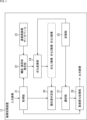
- FIG. 1 is a block diagram showing a configuration example of an image processing device according to a first embodiment of the present technology
- FIG. 4 is a diagram showing an example of information stored in a storage unit
- FIG. FIG. 4 is a diagram showing an example of information used for database learning
- 4 is a flowchart for explaining processing performed by the image processing apparatus
- FIG. 10 is a diagram showing an example of a case where image quality improvement signal processing succeeds and a case where it fails
- FIG. 2 is a diagram showing the flow of conventional image quality enhancement signal processing
- FIG. 10 is a diagram showing the flow of another conventional image quality enhancement signal processing
- It is a block diagram showing an example of composition of an image processing device concerning a 2nd embodiment of this art.
- FIG. 4 is a diagram showing an example of a database mixing method
- FIG. 10 is a diagram showing another example of a database mixing method
- It is a figure which shows the example of each mixing propriety of each kind of deterioration process.
- 4 is a flowchart for explaining processing performed by the image processing apparatus; It is a block diagram which shows the structural example of the hardware of a computer.
- FIG. 1 is a block diagram showing a configuration example of the image processing device 11 according to the first embodiment of the present technology.
- the image processing device 11 in FIG. 1 is, for example, a device that performs super-resolution processing to improve the image quality of an input image generated including a deterioration process.
- the image processing apparatus 11 includes an acquisition unit 21, a composition/subject estimation unit 22, a high-quality image database 23, a deterioration conversion unit 24, a storage unit 25, a similarity determination unit 26, a selection unit 27, and It is composed of an image quality improvement processing unit 28 .
- the acquisition unit 21 acquires an input image input to the image processing device 11 and supplies it to the composition/subject estimation unit 22, the similarity determination unit 26, and the image quality improvement processing unit 28.
- the composition/subject estimation unit 22 estimates the subject and composition of the input image supplied from the acquisition unit 21, and acquires a high-quality image from the high-quality image database 23 based on the estimation result. Specifically, the composition/subject estimation unit 22 selects a high-quality image having a subject and composition similar to those of the input image from among the high-quality images stored in the high-quality image database 23 . The composition/subject estimation unit 22 supplies the selected high-quality image to the degradation conversion unit 24 .
- the high-quality image database 23 stores various types of high-quality images.
- a high quality image is, for example, an image of higher quality than the input image. Note that the high-quality image database 23 may be provided on the cloud.
- the degradation conversion unit 24 generates a plurality of degraded images by applying degradation processing including different degradation processes to the high-quality images supplied from the composition/subject estimation unit 22 . Specifically, the degradation conversion unit 24 acquires all the information indicating the degradation process stored in the storage unit 25, and performs degradation processing including each degradation process on the high-quality image.
- FIG. 2 is a diagram showing an example of information stored in the storage unit 25. As shown in FIG.
- each deterioration process is stored in association with a database used for improving the image quality of the input image.
- the database stores, for example, network parameters for improving the image quality of the input image.
- deterioration process 1 is associated with database DB1
- deterioration process 2 is associated with database DB2.
- the deterioration process 3 and the database DB3 are associated with each other.
- the databases DB1 to DB3 are obtained through learning using a teacher image as a learning teacher and a student image as a learning student.
- FIG. 3 is a diagram showing an example of information used for learning of databases DB1 to DB3.
- Degradation process 1 For the learning of the database DB1, teacher images and student images obtained by subjecting the teacher images to deterioration processing including deterioration process 1 corresponding to the database DB1 as shown in the first row of FIG. 3 are used. be done.
- Degradation process 1 indicates that an image whose original size is SD (Standard Definition) is enlarged or reduced, and that it is coded by the AVC (Advanced Video Coding) coding method with a bit rate of 1 Mbps. .
- the degradation process corresponding to one database includes degradation processes of various categories.
- Degradation process 2 indicates, for example, that an image whose original size is 4K is enlarged or reduced, and that the image is encoded by the JPEG (Joint Photographic Experts Group) encoding method.
- Deterioration process 3 is, for example, that an image whose original size is HD (High Definition) is enlarged or reduced, and that it is encoded by MPEG (Moving Picture Experts Group) encoding method with a bit rate of 12 Mbps. show.
- HD High Definition
- MPEG Motion Picture Experts Group
- the degradation conversion unit 24 generates a degradation 1 image, a degradation 2 image, and a degradation 3 image by performing degradation processing including degradation processes 1 to 3 described above on the high-quality image.
- the degradation conversion unit 24 supplies these degraded images to the similarity determination unit 26 .
- the similarity determination unit 26 functions as a comparison unit that compares the input image supplied from the acquisition unit 21 with the deterioration 1 image, the deterioration 2 image, and the deterioration 3 image supplied from the deterioration conversion unit 24, respectively. Specifically, the similarity determination unit 26 calculates similarities between the input image and each of the deterioration 1 image, the deterioration 2 image, and the deterioration 3 image, and information indicating the similarity between the input image and each deterioration image. is supplied to the selection unit 27 .
- the selection unit 27 selects an application database used for improving the image quality of the input image from among the databases DB1 to DB3 stored in the storage unit 25 based on the comparison result by the similarity determination unit 26. Specifically, the selection unit 27 acquires from the storage unit 25 a database corresponding to the deterioration process of the degraded image having the highest degree of similarity with the input image, and supplies the database to the image quality enhancement processing unit 28 .
- the image quality enhancement processing unit 28 uses the database supplied from the selection unit 27, the image quality enhancement processing unit 28 performs image quality enhancement signal processing on the input image supplied from the acquisition unit 21, and generates an output image as an output result.
- step S1 the image processing device 11 learns databases corresponding to different deterioration processes.
- the database acquired as the learning result is stored in the storage unit 25 in association with the deterioration process of the student image used for learning of the database. Note that the process of step S1 only needs to be performed once as a preparation, and does not need to be performed each time an input image is input.
- step S2 the composition/subject estimation unit 22 estimates the composition and subject of the input image.
- step S3 the composition/subject estimation unit 22 acquires from the high-quality image database 23 a composition similar to the composition and subject of the input image and a high-quality image of the subject.
- step S4 the deterioration conversion unit 24 performs deterioration processing including a specific deterioration process on the high-quality image acquired by the composition/subject estimation unit 22 to generate a deteriorated image.
- step S5 the similarity determination unit 26 calculates and records the similarity between the input image and the degraded image.
- step S6 the degradation conversion unit 24 determines whether or not all degradation processes have been performed. For example, when the degradation conversion unit 24 generates a degraded image including all the degradation processes stored in the storage unit 25, it determines that all degradation processes have been performed.
- step S6 If it is determined in step S6 that all the deterioration processing has not been performed, the process returns to step S4, and the subsequent processing is repeated until the degrees of similarity between all the deteriorated images and the input image are calculated.
- step S6 If it is determined in step S6 that all deterioration processes have been performed, the process proceeds to step S7.
- step S7 the selection unit 27 selects, from among the databases stored in the storage unit 25, the database corresponding to the deterioration process of the degraded image having the highest degree of similarity with the input image as the applicable database.
- step S8 the image quality improvement processing unit 28 performs image quality improvement signal processing of the input image using the application database.
- FIG. 5 is a diagram showing an example of a case where the image quality improvement signal processing is successful and a case where it is unsuccessful.
- a high-quality NW (Network) is acquired by learning using teacher images and student images generated including deterioration process A.
- NW Network
- FIG. 5B when the input image A generated including the degradation process A is input to the image quality enhancement NW, the processing result of the image quality enhancement signal processing by the image quality enhancement NW is good.
- the image quality improvement signal processing by the image quality improvement NW is bad.
- an image without sharpness or an overemphasized image is output as the processing result of the image quality enhancement signal processing.
- FIG. 6 is a diagram showing the flow of conventional high image quality signal processing.
- the deterioration process of the input image is estimated as indicated by arrow #1 in FIG. , a learned database corresponding to the degradation process of the input image is selected. Thereafter, as indicated by arrow #3, the selected learned database is used to perform image quality enhancement signal processing, and as indicated by arrow #4, an output image is generated.
- the types of degradation processes that can be estimated are limited by the estimator.
- the estimator estimates only a specific degradation process among degradation processes such as camera blur due to focus or motion, dark area noise, distortion due to compression encoding, expansion, reduction, etc. Therefore, degradation other than estimable types is estimated.
- Process cannot be estimated.
- the estimator cannot, for example, estimate the degradation process of the input image encoded with the new encoding scheme. Further, for example, when an input image is generated including multiple deterioration processes in combination, the estimation accuracy of the estimator is lowered.
- the similarity is calculated by comparing the pixel values of the input image and the degraded image instead of selecting a database corresponding to the directly estimated degradation process of the input image. is selected as the apply database. That is, it is possible to select a process that can obtain the best processing result from among the image quality enhancement signal processes that can be performed by the image processing apparatus 11 . Since the degradation process of the input image is estimated using a method that can be expected to estimate even unknown types of degradation processes with a certain degree of accuracy, it is possible to handle input images that include unknown types of degradation processes. there is a possibility.
- FIG. 7 is a diagram showing the flow of another conventional high image quality signal processing.
- dashed arrows indicate the flow of learning
- solid arrows indicate the flow of increasing the image quality of the input image.
- a group of high-quality images different from the input image and a group of degraded images generated including a degradation process similar to the degradation process of the input image are prepared in advance.
- the deterioration converter 51A is trained to convert a high-quality image group into an image group generated by including a deterioration process similar to the deterioration process of the input image.
- learning of the image quality enhancement converter 52A that converts the degraded image group into the image group of high image quality is performed.
- the parameters of the degradation converter 51A are adjusted so that the degradation process of the conversion result by the degradation converter 51A is the same as the degradation process of the degraded image group.
- the parameters of the image quality enhancement converter 52A are adjusted so that the image quality of the conversion result by the image quality enhancement converter 52A is the same as the image quality of the high quality image group.
- the conversion result of the high-quality image group by the degradation converter 51A is input to the high-quality converter 52A so that the conversion result will be the same as the original high-quality image group. learning is done. Further, the deterioration converter 51A is trained so that the conversion result when the conversion result of the deteriorated image group by the image quality enhancement converter 52A is input to the deterioration converter 51A is the same as the original deteriorated image group. .
- the degraded image group generated including the degradation process of the input image cannot be prepared in advance.
- the parameters of the deterioration converter 51A may be adjusted so that the deterioration process of the conversion result of is the same as the deterioration process of the input image. Since a sufficient number of input images are required to improve the learning accuracy of the degradation converter 51A, the conversion accuracy of the degradation converter 51A is low when the input image is a single image. Therefore, since the current technology is not sufficient to imitate the degraded image, there is a possibility that the conversion result by the degraded converter 51A does not resemble the degraded image group or includes unnecessary degradation processes. Moreover, it is difficult to judge whether the conversion result by the deterioration converter 51A is accurate enough for the student image of the image quality improvement converter 52A.
- both the learning of the degradation converter 51A and the learning of the image quality enhancement converter 52A require a large amount of repeated calculations, which increases the time and calculation cost required for image quality enhancement signal processing.
- the accuracy of conversion by the image quality enhancement converter 52A includes double accuracy deterioration of the learning accuracy degradation of the degradation converter 51A and the learning accuracy degradation of the image quality enhancement converter 52A itself. It is difficult to improve the accuracy of conversion by the conversion converter 52A.
- the image processing device 11 of the present technology since the degradation process corresponding to each database that is a candidate for selection of the application database is known, the accuracy of the student images used for learning each database is ensured. Therefore, the accuracy of the image quality improvement signal processing for the input image generated including the deterioration process corresponding to each database is also improved.
- the image processing apparatus 11 selects a database that can improve the image quality of the input image with high accuracy even if the degradation process of the input image is unknown, and uses the selected database to enhance the input image. Image quality can be improved.
- FIG. 8 is a block diagram showing a configuration example of the image processing device 11 according to the second embodiment of the present technology.
- the same reference numerals are assigned to the same configurations as those in FIG. Duplicate explanations will be omitted as appropriate.
- the configuration of the image processing device 11 shown in FIG. 8 differs from the configuration of the image processing device 11 shown in FIG. 1 in that a mixing unit 101 is provided instead of the selection unit 27.
- the mixing unit 101 selects a plurality of databases related to improving the image quality of the input image from the databases stored in the storage unit 25 based on the comparison result by the similarity determination unit 26 . Specifically, the mixing unit 101 selects a plurality of databases corresponding to the degradation process of a predetermined number of degraded images having a high degree of similarity with the input image among the degraded images generated by the degradation conversion unit 24 .
- the mixing unit 101 mixes the selected multiple databases at a mixing ratio according to the degree of similarity with the input image, thereby generating an application database used for improving the image quality of the input image.
- the mixing unit 101 supplies the application database to the image quality enhancement processing unit 28 .
- the image quality enhancement processing unit 28 performs image quality enhancement signal processing on the input image using the application database supplied from the mixing unit 101, and generates an output image.
- FIG. 9 is a diagram showing an example of a database mixing method.
- each degradation process corresponding to the database is indicated by a combination of three categories: original image size, encoding bit rate, and encoding method.
- original image size SD, HD, and 4K are shown as the original image size types
- 1 Mbps, 10 Mbps, and 20 MBps are shown as the encoding bit rate types.
- AVC, MPEG, and JPEG are shown as types of encoding methods.
- each degradation process is classified on an independent plane for each type of coding scheme.
- the mixing unit 101 selects the type of encoding scheme with the highest degree of similarity. Specifically, mixing section 101 calculates the average similarity for each type of encoding method, and selects the type of encoding method with the highest average similarity. For example, mixing section 101 selects AVC as the coding scheme with the highest degree of similarity.
- mixing section 101 selects the top four degradation processes with the highest degree of similarity among the degradation processes of the selected coding scheme.
- four degradation processes A to D are selected.
- deterioration process A indicates that an image whose original size is HD is enlarged or reduced, and that the image is encoded by the AVC encoding method with a bit rate of 20 Mbps
- deterioration process B indicates that the original size is Indicates that a 4K image is scaled up or down, and encoded with the AVC coding method at a bit rate of 20 Mbps.
- Degradation process C indicates that an image whose original size is HD is enlarged or reduced, and that it is encoded by the AVC encoding method with a bit rate of 10 Mbps.
- Degradation process D indicates that the original size is 4K. Indicates that the image is scaled up or down and encoded with the AVC encoding method at a bit rate of 10 Mbps.
- the mixing unit 101 weights the databases respectively corresponding to the four degradation processes according to the degrees of similarity, and mixes the four databases.
- a database corresponding to the deterioration process of the input image indicated by the colored circle in FIG. 9 is generated by mixing the databases corresponding to the deterioration processes A to D, respectively.
- the mixDB value which is the filter coefficients after mixing, is represented by the following formula (1).
- the degrees of similarity A to D indicate the degrees of similarity between the input image and the degraded image generated including the degradation processes A to D, respectively, and are represented by values of 0.0 to 1.0.
- DB(A) to DB(D) denote filter coefficients corresponding to the deterioration processes A to D, respectively.
- FIG. 10 is a diagram showing another example of a database mixing method.
- each degradation process corresponding to the database is indicated by a combination of four categories: original image size, encoding bit rate, encoding method, and ISO sensitivity.
- original image size For example, assume that each degradation process corresponding to the database is indicated by a combination of four categories: original image size, encoding bit rate, encoding method, and ISO sensitivity.
- SD, HD, and 4K are shown as the original image size types, and 1 Mbps, 10 Mbps, and 20 MBps are shown as the encoding bit rate types.
- AVC, MPEG, and JPEG are shown as types of encoding methods.
- each degradation process is indicated by points on the three axes of original image size, encoding bit rate, and ISO sensitivity.
- Each space is independent for each coding method, and the mixing unit 101 does not mix databases corresponding to degradation processes of different types of coding methods.
- the mixing unit 101 selects the type of encoding scheme with the highest degree of similarity. Specifically, mixing section 101 calculates the average similarity for each type of encoding method, and selects the type of encoding method with the highest average similarity. For example, mixing section 101 selects AVC as the coding scheme with the highest degree of similarity.
- mixing section 101 selects the top eight degradation processes with the highest degree of similarity among the degradation processes of the selected coding scheme.
- eight deterioration processes A to H are selected.
- the mixing unit 101 weights the databases respectively corresponding to the eight degradation processes according to their similarities, and mixes the eight databases.
- a database corresponding to the degradation process of the input image indicated by the colored circle in FIG. 10 is generated by mixing the databases corresponding to the degradation processes A to H, respectively. If the database is represented in the form of filter coefficients, the mixDB value is represented by Equation (2) below.
- the degrees of similarity A to H indicate the degrees of similarity between the input image and the degraded image generated including the degradation processes A to H, respectively, and are represented by values of 0.0 to 1.0.
- DB(A) through DB(H) denote filter coefficients corresponding to the degradation processes A through H, respectively.
- the applicable database may be selected from databases generated by mixing databases corresponding to the top eight degradation processes with the highest similarity for each encoding method.
- Categories of deterioration processes are classified, for example, by imaging conditions and coding conditions.
- the imaging condition category includes the original size of the image, ISO sensitivity, and frame rate.
- Categories of encoding conditions include encoding scheme and encoding bit rate (quality).
- the original size of the image is included in a representative category of deterioration process.
- the encoding method and encoding bit rate are degraded because the encoding method differs depending on the camera, broadcasting equipment, and editing equipment used, and the encoding method and encoding bit rate fluctuate depending on the image broadcast route and distribution route. Included in the representative category of processes. Since the amount of noise contained in an image changes depending on the ISO sensitivity at the time of imaging, the ISO sensitivity is included in a representative category of the deterioration process of the input image. Since the frame rate differs depending on the camera settings at the time of imaging, the frame rate is included in the representative category of deterioration process.
- a category is set in advance in which databases corresponding to different types of degradation processes cannot be mixed.
- FIG. 11 is a diagram showing an example of whether or not each deterioration process category can be mixed.
- the mixing unit 101 does not mix databases corresponding to degradation processes with different types of encoding methods, and does not mix databases corresponding to degradation processes with different types of frame rates. If there are a plurality of categories that cannot be mixed, the mixing unit 101 sequentially selects specific types of degradation processes based on the average similarity for each type of degradation process in each category. For example, the mixing unit 101 calculates the average similarity for each frame rate and selects the frame rate with the highest average similarity. After that, mixing section 101 calculates the average similarity for each encoding method, and selects the encoding method with the highest average similarity.
- the mixing unit 101 After selecting a specific type of deterioration process from the categories that cannot be mixed, the mixing unit 101 weights the database corresponding to the deterioration process indicated by the combination of the categories that can be mixed according to each similarity. and calculate the mixDB value. When there are four categories that can be mixed, it is desirable that 16 databases are mixed, but 16 databases do not necessarily have to be mixed.
- steps S51 to S56 is the same as the processing of steps S1 to S6 in FIG.
- a degraded image is generated by degrading a high-quality image of a composition and a subject similar to the composition of the input image and the subject. Also, the degree of similarity between each degraded image and the input image is calculated and recorded.
- step S57 the mixing unit 101 selects, from the databases stored in the storage unit 25, a database corresponding to the deterioration process of the degraded image having the highest degree of similarity with the input image.
- step S58 the mixing unit 101 determines whether the highest degree of similarity is equal to or less than the threshold.
- step S58 If it is determined in step S58 that the highest degree of similarity is equal to or less than the threshold, the process proceeds to step S59.
- step S59 the mixing unit 101 mixes the databases according to the degree of similarity to generate an application database. After the databases have been mixed, processing proceeds to step S60.
- step S58 determines that the highest degree of similarity exceeds the threshold.
- step S59 is skipped, and the mixing unit 101 sets the database corresponding to the deterioration process with the highest degree of similarity as the applicable database. After that, the process proceeds to step S60.
- step S60 the image quality enhancement processing unit 28 performs image quality enhancement signal processing of the input image using the application database.
- the image processing apparatus 11 can accurately improve the image quality of the input image by combining the databases that it possesses when it does not have a database suitable for improving the image quality of the input image. can generate a database that allows The image processing apparatus 11 can improve the image quality of the input image using the newly generated database.
- the image processing device 11 can perform image quality enhancement signal processing on images such as old movies and photographs whose deterioration process is unknown.
- the image processing apparatus 11 can perform image quality enhancement signal processing on an image whose degradation process is difficult to estimate because it has been compression-encoded, enlarged, or reduced each time it is edited.
- This technology can be applied, for example, to improving the image quality of images captured by cameras whose imaging characteristics are unknown.
- the image processing device 11 of the present technology can be used in video production sites where video editing is performed after restoring the deterioration of the previous process, photo restoration, and video where the used camera and editing process are unknown. It is possible to use it for various video distribution systems.
- the series of processes described above can be executed by hardware or by software.
- a program that constitutes the software is installed from a program recording medium into a computer built into dedicated hardware or a general-purpose personal computer.
- FIG. 13 is a block diagram showing an example of the hardware configuration of a computer that executes the series of processes described above by a program.
- a CPU (Central Processing Unit) 501 , a ROM (Read Only Memory) 502 and a RAM (Random Access Memory) 503 are interconnected by a bus 504 .
- An input/output interface 505 is further connected to the bus 504 .
- the input/output interface 505 is connected to an input unit 506 such as a keyboard and a mouse, and an output unit 507 such as a display and a speaker.
- the input/output interface 505 is also connected to a storage unit 508 including a hard disk or nonvolatile memory, a communication unit 509 including a network interface, and a drive 510 for driving a removable medium 511 .
- the CPU 501 loads, for example, a program stored in the storage unit 508 into the RAM 503 via the input/output interface 505 and the bus 504 and executes the above-described series of processes. is done.
- Programs executed by the CPU 501 are, for example, recorded on the removable media 511, or provided via wired or wireless transmission media such as local area networks, the Internet, and digital broadcasting, and installed in the storage unit 508.
- the program executed by the computer may be a program in which processing is performed in chronological order according to the order described in this specification, or a program in which processing is performed in parallel or at necessary timing such as when a call is made. It may be a program that is carried out.
- a system means a set of multiple components (devices, modules (parts), etc.), and it does not matter whether all the components are in the same housing. Therefore, a plurality of devices housed in separate housings and connected via a network, and a single device housing a plurality of modules in one housing, are both systems. .
- Embodiments of the present technology are not limited to the above-described embodiments, and various modifications are possible without departing from the gist of the present technology.
- this technology can take the configuration of cloud computing in which a single function is shared by multiple devices via a network and processed jointly.
- each step described in the flowchart above can be executed by a single device, or can be shared by a plurality of devices.
- one step includes multiple processes
- the multiple processes included in the one step can be executed by one device or shared by multiple devices.
- the present technology can also take the following configurations.
- a degradation conversion unit that generates a plurality of degraded images by performing degradation processing including degradation processes different from each other on a second image that is different from the input first image; a comparison unit that compares the first image with each of the plurality of degraded images; and a selection unit that selects the parameter for improving the image quality of the first image from among the parameters corresponding to the deterioration process of the plurality of degraded images, based on the comparison result of the comparison unit.
- the parameters use a teacher image serving as a learning teacher and a student image serving as a learning student obtained by subjecting the teacher image to the deterioration process including the deterioration process corresponding to the parameter.
- the image processing device according to (1) above, which is obtained by learning through training.
- the comparison unit calculates a degree of similarity between the first image and each of the plurality of degraded images;
- the selection unit selects the parameter corresponding to the deterioration process of the degraded image having the highest degree of similarity with the first image as an application parameter used for improving the image quality of the first image.
- (6) The image processing device according to (5), wherein the second image is an image having a subject and composition similar to those of the first image.
- the image processing device according to any one of (1) to (6), wherein the second image has a higher image quality than the first image.
- the selection unit mixes the plurality of selected parameters to generate an application parameter used to improve the image quality of the first image.
- the selection unit selects, from among the plurality of degraded images, the plurality of parameters corresponding to the deterioration process of a predetermined number of the degraded images having the highest degree of similarity with the first image.
- the image processing device according to .
- the image processing device (10) The image processing device according to (9), wherein the selection unit mixes the plurality of parameters at a mixing ratio according to the degree of similarity between the first image and a predetermined number of the degraded images.
- the image processing device (11) The image processing device according to (10), wherein the selection unit selects a plurality of the parameters to be mixed from among the parameters corresponding to the deterioration process of a specific type. (12) Based on the average value of the similarities calculated for each type of the deterioration process in a category in which the parameters corresponding to the deterioration processes of different types cannot be mixed, the selection unit selects the specific type of the The image processing apparatus according to (11), wherein a deterioration process is selected. (13) The image processing device according to any one of (9) to (12), wherein the selection unit selects a plurality of the parameters when the highest degree of similarity is lower than a predetermined threshold.
- the image processing device (14) The image processing device according to (12), wherein the category of the deterioration process is classified according to at least one of an imaging condition and an encoding condition.
- the imaging conditions include at least one of an original size of an image, an ISO sensitivity, and a frame rate.
- the encoding condition includes at least one of an encoding method and quality.
- the image processing device generating a plurality of degraded images by performing degradation processing including degradation processes different from each other on a second image different from the input first image; comparing the first image with each of the plurality of degraded images; Selecting the parameter for improving the image quality of the first image from parameters corresponding to the deterioration process of the plurality of degraded images based on a comparison result between the first image and the degraded image. Processing method.
- a computer-readable recording medium that records a program for executing
Landscapes
- Engineering & Computer Science (AREA)
- Physics & Mathematics (AREA)
- General Physics & Mathematics (AREA)
- Theoretical Computer Science (AREA)
- Quality & Reliability (AREA)
- Computer Vision & Pattern Recognition (AREA)
- Multimedia (AREA)
- Signal Processing (AREA)
- Image Processing (AREA)
Priority Applications (2)
| Application Number | Priority Date | Filing Date | Title |
|---|---|---|---|
| US18/723,603 US20250054110A1 (en) | 2022-01-04 | 2022-12-20 | Image processing device, image processing method, and recording medium |
| JP2023572404A JPWO2023132223A1 (https=) | 2022-01-04 | 2022-12-20 |
Applications Claiming Priority (2)
| Application Number | Priority Date | Filing Date | Title |
|---|---|---|---|
| JP2022000185 | 2022-01-04 | ||
| JP2022-000185 | 2022-01-04 |
Publications (1)
| Publication Number | Publication Date |
|---|---|
| WO2023132223A1 true WO2023132223A1 (ja) | 2023-07-13 |
Family
ID=87073666
Family Applications (1)
| Application Number | Title | Priority Date | Filing Date |
|---|---|---|---|
| PCT/JP2022/046797 Ceased WO2023132223A1 (ja) | 2022-01-04 | 2022-12-20 | 画像処理装置、画像処理方法、および記録媒体 |
Country Status (3)
| Country | Link |
|---|---|
| US (1) | US20250054110A1 (https=) |
| JP (1) | JPWO2023132223A1 (https=) |
| WO (1) | WO2023132223A1 (https=) |
Citations (4)
| Publication number | Priority date | Publication date | Assignee | Title |
|---|---|---|---|---|
| JP2005253000A (ja) * | 2004-03-08 | 2005-09-15 | Mitsubishi Electric Corp | 画像処理装置 |
| WO2015022771A1 (ja) * | 2013-08-15 | 2015-02-19 | 日本電気株式会社 | 画像処理を実行する情報処理装置及び画像処理方法 |
| JP2019032654A (ja) * | 2017-08-07 | 2019-02-28 | キヤノン株式会社 | 画像処理装置、及び、画像処理方法、コンピュータプログラム |
| JP2021060847A (ja) * | 2019-10-08 | 2021-04-15 | 株式会社ザクティ | ノイズ除去システム |
Family Cites Families (4)
| Publication number | Priority date | Publication date | Assignee | Title |
|---|---|---|---|---|
| US9436981B2 (en) * | 2011-12-12 | 2016-09-06 | Nec Corporation | Dictionary creation device, image processing device, image processing system, dictionary creation method, image processing method, and program |
| US11030723B2 (en) * | 2017-02-20 | 2021-06-08 | Sony Corporation | Image processing apparatus, image processing method, and program |
| JP6772112B2 (ja) * | 2017-07-31 | 2020-10-21 | 株式会社日立製作所 | 医用撮像装置及び医用画像処理方法 |
| WO2022070236A1 (ja) * | 2020-09-29 | 2022-04-07 | 株式会社日立ハイテク | 画質改善システム及び画質改善方法 |
-
2022
- 2022-12-20 WO PCT/JP2022/046797 patent/WO2023132223A1/ja not_active Ceased
- 2022-12-20 JP JP2023572404A patent/JPWO2023132223A1/ja active Pending
- 2022-12-20 US US18/723,603 patent/US20250054110A1/en active Pending
Patent Citations (4)
| Publication number | Priority date | Publication date | Assignee | Title |
|---|---|---|---|---|
| JP2005253000A (ja) * | 2004-03-08 | 2005-09-15 | Mitsubishi Electric Corp | 画像処理装置 |
| WO2015022771A1 (ja) * | 2013-08-15 | 2015-02-19 | 日本電気株式会社 | 画像処理を実行する情報処理装置及び画像処理方法 |
| JP2019032654A (ja) * | 2017-08-07 | 2019-02-28 | キヤノン株式会社 | 画像処理装置、及び、画像処理方法、コンピュータプログラム |
| JP2021060847A (ja) * | 2019-10-08 | 2021-04-15 | 株式会社ザクティ | ノイズ除去システム |
Also Published As
| Publication number | Publication date |
|---|---|
| US20250054110A1 (en) | 2025-02-13 |
| JPWO2023132223A1 (https=) | 2023-07-13 |
Similar Documents
| Publication | Publication Date | Title |
|---|---|---|
| Chen et al. | A new journey from SDRTV to HDRTV | |
| Yu et al. | Predicting the quality of compressed videos with pre-existing distortions | |
| Ni et al. | SCID: A database for screen content images quality assessment | |
| Wang | Objective image quality assessment: facing the real-world challenges | |
| CN113052764B (zh) | 一种基于残差连接的视频序列超分重建方法 | |
| CN111385567B (zh) | 一种超高清视频质量评价方法及装置 | |
| US20180035117A1 (en) | Image encoding device and method | |
| CN113066022A (zh) | 一种基于高效时空信息融合的视频比特增强方法 | |
| CN110177282B (zh) | 一种基于srcnn的帧间预测方法 | |
| CN108846800A (zh) | 一种图像超分辨率重建的无参考图像质量评价方法 | |
| CN111524110B (zh) | 视频质量的评价模型构建方法、评价方法及装置 | |
| CN113781321A (zh) | 图像高亮区域的信息补偿方法、装置、设备及存储介质 | |
| CN116405684A (zh) | 一种自适应选择参考帧的会话视频语义压缩框架及方法 | |
| Men et al. | Visual quality assessment for interpolated slow-motion videos based on a novel database | |
| Kawayoke et al. | NR objective continuous video quality assessment model based on frame quality measure | |
| CN117975326A (zh) | 一种基于边缘计算的增材制造在线监测方法及系统 | |
| Zhao et al. | LRGD: Low-rank guided diffusion for robust image transmission in semantic communication | |
| Vora et al. | Analysis of compressed image quality assessments, m | |
| CN116074528B (zh) | 视频编码方法及装置、编码信息调度方法及装置 | |
| Majeedi et al. | Full reference video quality assessment for machine learning-based video codecs | |
| CN113949899B (zh) | 视频质量评估方法及装置 | |
| WO2023132223A1 (ja) | 画像処理装置、画像処理方法、および記録媒体 | |
| CN121033240A (zh) | 一种基于混合自注意力和小波变换的浅景深图像渲染方法 | |
| KR20240024921A (ko) | 이미지 또는 비디오를 인코딩/디코딩하기 위한 방법들 및 장치들 | |
| De Decker et al. | No-reference vmaf: a deep neural network-based approach to blind video quality assessment |
Legal Events
| Date | Code | Title | Description |
|---|---|---|---|
| 121 | Ep: the epo has been informed by wipo that ep was designated in this application |
Ref document number: 22918808 Country of ref document: EP Kind code of ref document: A1 |
|
| ENP | Entry into the national phase |
Ref document number: 2023572404 Country of ref document: JP Kind code of ref document: A |
|
| WWE | Wipo information: entry into national phase |
Ref document number: 18723603 Country of ref document: US |
|
| NENP | Non-entry into the national phase |
Ref country code: DE |
|
| 122 | Ep: pct application non-entry in european phase |
Ref document number: 22918808 Country of ref document: EP Kind code of ref document: A1 |