WO2023132132A1 - 画像送信システムおよび画像送信装置 - Google Patents
画像送信システムおよび画像送信装置 Download PDFInfo
- Publication number
- WO2023132132A1 WO2023132132A1 PCT/JP2022/042547 JP2022042547W WO2023132132A1 WO 2023132132 A1 WO2023132132 A1 WO 2023132132A1 JP 2022042547 W JP2022042547 W JP 2022042547W WO 2023132132 A1 WO2023132132 A1 WO 2023132132A1
- Authority
- WO
- WIPO (PCT)
- Prior art keywords
- image
- performer
- seat
- line
- sight
- Prior art date
- Legal status (The legal status is an assumption and is not a legal conclusion. Google has not performed a legal analysis and makes no representation as to the accuracy of the status listed.)
- Ceased
Links
Images








Classifications
-
- G—PHYSICS
- G06—COMPUTING OR CALCULATING; COUNTING
- G06F—ELECTRIC DIGITAL DATA PROCESSING
- G06F3/00—Input arrangements for transferring data to be processed into a form capable of being handled by the computer; Output arrangements for transferring data from processing unit to output unit, e.g. interface arrangements
- G06F3/14—Digital output to display device ; Cooperation and interconnection of the display device with other functional units
-
- G—PHYSICS
- G06—COMPUTING OR CALCULATING; COUNTING
- G06F—ELECTRIC DIGITAL DATA PROCESSING
- G06F3/00—Input arrangements for transferring data to be processed into a form capable of being handled by the computer; Output arrangements for transferring data from processing unit to output unit, e.g. interface arrangements
- G06F3/01—Input arrangements or combined input and output arrangements for interaction between user and computer
- G06F3/011—Arrangements for interaction with the human body, e.g. for user immersion in virtual reality
- G06F3/013—Eye tracking input arrangements
-
- G—PHYSICS
- G06—COMPUTING OR CALCULATING; COUNTING
- G06T—IMAGE DATA PROCESSING OR GENERATION, IN GENERAL
- G06T7/00—Image analysis
-
- G—PHYSICS
- G06—COMPUTING OR CALCULATING; COUNTING
- G06T—IMAGE DATA PROCESSING OR GENERATION, IN GENERAL
- G06T7/00—Image analysis
- G06T7/70—Determining position or orientation of objects or cameras
-
- H—ELECTRICITY
- H04—ELECTRIC COMMUNICATION TECHNIQUE
- H04N—PICTORIAL COMMUNICATION, e.g. TELEVISION
- H04N21/00—Selective content distribution, e.g. interactive television or video on demand [VOD]
- H04N21/20—Servers specifically adapted for the distribution of content, e.g. VOD servers; Operations thereof
- H04N21/21—Server components or server architectures
- H04N21/218—Source of audio or video content, e.g. local disk arrays
- H04N21/2187—Live feed
-
- H—ELECTRICITY
- H04—ELECTRIC COMMUNICATION TECHNIQUE
- H04N—PICTORIAL COMMUNICATION, e.g. TELEVISION
- H04N21/00—Selective content distribution, e.g. interactive television or video on demand [VOD]
- H04N21/20—Servers specifically adapted for the distribution of content, e.g. VOD servers; Operations thereof
- H04N21/25—Management operations performed by the server for facilitating the content distribution or administrating data related to end-users or client devices, e.g. end-user or client device authentication, learning user preferences for recommending movies
- H04N21/258—Client or end-user data management, e.g. managing client capabilities, user preferences or demographics, processing of multiple end-users preferences to derive collaborative data
-
- H—ELECTRICITY
- H04—ELECTRIC COMMUNICATION TECHNIQUE
- H04N—PICTORIAL COMMUNICATION, e.g. TELEVISION
- H04N21/00—Selective content distribution, e.g. interactive television or video on demand [VOD]
- H04N21/20—Servers specifically adapted for the distribution of content, e.g. VOD servers; Operations thereof
- H04N21/25—Management operations performed by the server for facilitating the content distribution or administrating data related to end-users or client devices, e.g. end-user or client device authentication, learning user preferences for recommending movies
- H04N21/266—Channel or content management, e.g. generation and management of keys and entitlement messages in a conditional access system, merging a VOD unicast channel into a multicast channel
- H04N21/2665—Gathering content from different sources, e.g. Internet and satellite
Definitions
- the present invention relates to an image transmission system and an image transmission device.
- Patent Literature 1 discloses a live video distribution system.
- the image data processing device switches and outputs the input plural camera images based on the music analysis data or the result of the analysis performed by the image analysis unit.
- a specific person is detected from multiple camera images, and the specific person is switched to the main image according to changes in the sound or image in the music, and the image is output.
- the video data processing device switches to a video according to a request transmitted from the user terminal, outputs the video, and transmits the video to the user terminal via the video distribution device and the streaming server.
- Online live performances are highly convenient in that even if viewers cannot come directly to the live venue, they will be able to watch the live performance.
- the experience of individual interaction between the performer and the audience such as eye contact between the performer and the audience, cannot be obtained in online live performances.
- the image can be viewed by all viewers watching the online live performance. Therefore, the viewer does not perceive that the performer has turned his or her gaze.
- viewing online live performances has the problem that the relationship between viewers and performers is weaker than viewing live performances at live venues, and viewer satisfaction is low.
- the purpose of the present invention is to improve the viewer's satisfaction in transmitting the video of the demonstration.
- An image transmission system includes a first imaging device that captures a first image of a first performer in the physical space from a position of a virtual first seat set in the physical space; a second imaging device that captures a second image including the performer from a position different from the position of the first imaging device; a transmission control unit that transmits an image; and a detection unit that detects the line-of-sight direction of the performer, wherein the transmission control unit detects that the line-of-sight direction of the performer is directed toward the virtual first seat. Based on this, the first image is transmitted to the terminal device.
- the image transmission device transmits the first image of the performer in the physical space captured by the first imaging device from the position of the virtual first seat set in the physical space.
- a first acquisition unit that acquires;
- a second acquisition unit that acquires a second image including the performer captured by a second imaging device from a position different from that of the first imaging device;
- a transmission control unit that transmits the second image to the associated terminal device of the viewer, and a detection unit that detects the line-of-sight direction of the performer.
- the first image is transmitted to the terminal device based on facing the first virtual seat.
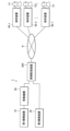
- FIG. 1 is a block diagram showing the configuration of an image transmission system 1 according to a first embodiment
- FIG. 2 is an explanatory diagram schematically showing the arrangement of a first imaging device 10 and a second imaging device 20
- FIG. FIG. 3 is an explanatory diagram schematically showing a first image PC1
- FIG. 3 is an explanatory diagram schematically showing a first image PC1
- FIG. It is an explanatory view showing a 2nd picture PC2 typically.
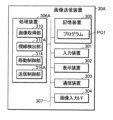
- 3 is a block diagram showing the configuration of an image transmission device 30A
- FIG. FIG. 4 is an explanatory diagram schematically showing the line-of-sight direction L of a performer
- FIG. 7 is an explanatory diagram schematically showing switching timings of transmission images corresponding to the line-of-sight direction L shown in FIG.
- FIG. 11 is a block diagram showing the configuration of an image transmission system 2 according to a second embodiment;
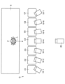
- FIG. 11 is an explanatory diagram schematically showing the arrangement of first imaging devices 10-1 to 10-7 in the second embodiment;
- 3 is a block diagram showing the configuration of an image transmission device 30B;
- FIG. 11 is an explanatory diagram showing an example of an online live viewing screen on the terminal device 40-1;
- FIG. 11 is an explanatory diagram showing an example of an online live viewing screen on the terminal device 40-1;
- FIG. 11 is an explanatory diagram showing an example of an online live viewing screen on the terminal device 40-1;
- FIG. 11 is an explanatory diagram showing an example of an online live viewing screen on the terminal device 40-1;
- 11 is an explanatory diagram schematically showing switching of transmission images performed by a transmission control unit 316B; It is a flowchart which shows operation
- FIG. 1 is a block diagram showing the configuration of an image transmission system 1 according to the first embodiment.
- the image transmission system 1 includes a first imaging device 10, a moving mechanism 50, a second imaging device 20, and an image transmission device 30A.
- the image transmission device 30A is connected via a communication network N to a plurality of terminal devices 40-1 to 40-n (n is any integer equal to or greater than 1).
- the respective terminal devices 40-1 to 40-n are held by different viewers V1 to Vn.
- viewers V1 to V7 are associated one-to-one with seats C1 to C7 (see FIG. 2), which will be described later. Viewers V1 to V7 hold terminal devices 40-1 to 40-7, respectively. Therefore, FIG.
- the image transmission system 1 is for transmitting images captured by the first imaging device 10 and the second imaging device 20 (first image PC1 and second image PC2 described later) to the terminal devices 40-1 to 40-7.
- the first imaging device 10 and the second imaging device 20 capture an image of a performer P (see FIG. 2) who is performing a performance such as singing.
- a viewer Vi uses a terminal device 40-i to view an image showing a performer P performing a performance. That is, the image transmission system 1 is used for online live transmission.
- the online live is a so-called live distribution in which images of the performance are transmitted in real time.
- the online live is not limited to this, and may be a system in which pre-recorded images of the demonstration are transmitted after the fact.
- the terminal device 40-i is an information processing device such as a smart phone, tablet terminal, personal computer, smart glasses, or VR glasses.
- the terminal device 40-i includes an image display device such as a display, a speaker, and a communication device connected to the communication network N, for example.
- the first imaging device 10 has an imaging optical system and an imaging element.
- An imaging optical system is an optical system that includes at least one imaging lens.
- the imaging optical system may have various optical elements such as a prism, or may have a zoom lens, a focus lens, or the like.
- the imaging device is, for example, a CCD (Charge Coupled Device) image sensor or a CMOS (Complementary MOS) image sensor.
- the first imaging device 10 also includes an interface for outputting image data to the image transmission device 30A.
- the first imaging device 10 and the image transmission device 30A may be connected by wire or may be connected by radio.
- the second imaging device 20 also has the same configuration as the first imaging device 10 .
- the first imaging device 10 and the second imaging device 20 are, for example, video cameras.
- An image captured by the first imaging device 10 is called a first image PC1, and image data corresponding to the first image PC1 is called first image data.
- An image captured by the second imaging device 20 is called a second image PC2, and image data corresponding to the second image PC2 is called second image data.
- the first imaging device 10 and the second imaging device 20 capture moving images.
- the first imaging device 10 captures an image at a predetermined frame rate, generates first image data corresponding to the first image PC1, and outputs the generated first image data to the image transmission device 30A.
- the second imaging device 20 similarly generates second image data corresponding to the second image PC2, and outputs the generated second image data to the image transmission device 30A.
- FIG. 2 is an explanatory diagram schematically showing the arrangement of the first imaging device 10 and the second imaging device 20.
- FIG. FIG. 2 is a diagram of Theater G viewed from above.
- the space inside the theater G is an example of the real space.
- the first imaging device 10 and the second imaging device 20 capture an image of the performer P in the theater G.
- the performer P performs a live performance such as singing on the stage S installed in the theater G.
- the performance is not limited to singing, and may be, for example, acting or dancing.
- the space within the theater G is relatively small, and the gaze direction L of the performer P can be identified from each seat C1-C7.
- a plurality of virtual seats C1 to C7 are arranged in Theater G.
- the seat C1 is the first seat and the seat C2 is the second seat
- the seat C2 is arranged in the theater G at a physical position different from the physical position of the seat C1.
- a seat Ci an arbitrary integer from 1 to 7
- the seats C1 to C7 are obtained by dividing the floor of the theater G into a plurality of sections and assigning identification information (seat number) to each section.
- the seats C1 to C7 may be chairs actually installed in the theater G.
- Viewers V1 to V7 are associated with the respective seats C1 to C7.
- seat C1 is associated with viewer V1. That is, the seat Ci is associated with the viewer Vi.
- the terminal device 40-i held by the viewer Vi may be referred to as the terminal device 40-i associated with the seat Ci.
- Viewers Vi are assigned seats Ci when they apply to watch online live (or after applying and before the start of the live). Which of the seats C1 to C7 is assigned to the viewer Vi may be determined by the viewer Vi himself or may be determined by lottery or the like. If a charge is required for viewing the online live, the charge may vary according to the positions of the seats C1 to C7. For example, the closer the seat Ci is to the center of the stage S, the higher the fare may be.
- a plurality of viewers Vi-1, Vi-2, . . . may be associated with one seat Ci.
- all the viewers V1 to Vj (j is an arbitrary integer) watching the online live are not assigned to the same seat Ci. This is because if all the viewers V1 to Vj are assigned to the same seat Ci, all the viewers V1 to Vj view the same image, which is substantially equivalent to no seat Ci being assigned. .
- the first imaging device 10 captures a first image PC1 of the performer P performing the performance in the theater G from the position of the seat Ci virtually arranged in the theater G.
- the first imaging device 10 is movable between the seats C1 to C7.
- the first imaging device 10 captures an image of the performer P as a first image PC1 from any position on the seats C1 to C7. For example, when the first imaging device 10 is located at the seat C1, an image of the performer P is captured as the first image PC1 from the position of the seat C1. Also, when the first imaging device 10 is located at the seat C2, an image of the performer P is captured as the first image PC1 from the position of the seat C2.
- the first imaging device 10 is mounted on the moving mechanism 50 .
- the moving mechanism 50 moves the first imaging device 10 among the seats C1 to C7.
- the movement mechanism 50 moves the first imaging device 10 based on the control of the movement control section 314, which will be described later.
- the moving mechanism 50 has a rail 52 , a main body 54 and an arm 56 .
- Rails 52 are installed along the arrangement of seats C1 to C7.
- the main body 54 accommodates the drive wheels that move on the rails 52, actuators that rotate the drive wheels, and the like.
- the arm 56 has one end fixed to the main body 54 and the other end fixed to the first imaging device 10 .
- the first imaging device 10 moves left and right in the theater G.
- the arm 56 is connected to an actuator (not shown) and can extend and contract vertically. Therefore, the first imaging device 10 can move up and down in the theater G as well.
- the person in charge of imaging may move the first imaging device 10.
- 3A and 3B are explanatory diagrams schematically showing the first image PC1.
- the imaging magnification of the first imaging device 10 is set so that the face of the performer P mainly occupies a large part of the image.
- the viewer Vi can grasp the facial expression of the performer P, the line-of-sight direction L (see FIG. 2), and the like.
- FIG. 3A shows the first image PC1-A captured from the position of the seat C4 when the line-of-sight direction L of the performer P faces the seat C4 as shown in FIG.
- the performer P faces the first imaging device 10 (seat C4). appear.
- FIG. 3B shows the first image PC1-B captured from the position of the seat C1 when the line-of-sight direction L of the performer P faces the seat C4 as shown in FIG.
- the viewer Vi viewing the first image PC1-B does not see the performer P facing himself.
- the second imaging device 20 captures a second image PC2 including the performer P from a position different from that of the first imaging device 10 .
- the second imaging device 20 images the entire stage S from a position farther from the stage S than the first imaging device 10 .
- the position of the second imaging device 20 may be fixed, or, like the first imaging device 10, it may be mounted on the moving mechanism 50 and movable within the theater G.
- FIG. Also, in the theater G, a plurality of imaging devices corresponding to the second imaging device 20 may be installed. For example, as shown in FIG. 2, in addition to an imaging device that images the stage S from the front, an imaging device that images the stage S from the right side and an imaging device that images the stage S from the left side are installed as the second imaging devices 20. may
- FIG. 4 is an explanatory diagram schematically showing the second image PC2.
- a wide range of the stage S and the whole body of the performer P are shown in the second image PC2 shown in FIG.
- the viewer Vi can grasp the body movements of the performer P, the production on the stage S, and the like.
- the proportion of the actor P in the first image PC1 is greater than the proportion of the actor P in the second image PC2.
- the imaging magnification of the first image PC1 is greater than the imaging magnification of the second image PC2.
- FIG. 5 is a block diagram showing the configuration of the image transmission device 30A.
- the image transmission device 30A is, for example, a computer, and transmits the first image PC1 and the second image PC2 to the terminal devices 40-1 to 40-7.
- the image transmission device 30A includes an input device 301, a display device 302, a communication device 303, an image input interface (I/F) 304, a storage device 305, a processing device 306A, and a bus 307.
- the input device 301, the display device 302, the communication device 303, the image input interface 304, the storage device 305, and the processing device 306A are interconnected by a bus 307 for communicating information.
- the bus 307 may be configured using a single bus, or may be configured using different buses between devices.
- the input device 301 is a device that receives operations from the administrator of the image transmission device 30A.
- the input device 301 includes a pointing device such as a keyboard, touch pad, touch panel, or mouse.
- the input device 301 may also serve as the display device 302 .
- the display device 302 is a device that displays images and character information.
- the display device 302 displays various images under the control of the processing device 306A.
- various display panels such as a liquid crystal display panel and an organic EL display panel are preferably used as the display device 302 .
- the communication device 303 communicates with the terminal devices 40-1 to 40-7 using wireless communication or wired communication.
- the communication device 303 has an interface connectable to the communication network N, and communicates with the terminal devices 40-1 to 40-7 via the communication network N.
- the image input interface 304 is a connection interface with the first imaging device 10 and the second imaging device 20 . Via the image input interface 304, the first image data and the second image data are input to the image transmission device 30A.
- the storage device 305 is a recording medium readable by the processing device 306A.
- Storage device 305 includes, for example, non-volatile memory and volatile memory.
- Non-volatile memories are, for example, ROM (Read Only Memory), EPROM (Erasable Programmable Read Only Memory) and EEPROM (Electrically Erasable Programmable Read Only Memory).
- Volatile memory is, for example, RAM (Random Access Memory).
- Storage device 305 stores program PG1.
- the program PG1 is a program for operating the image transmission device 30A.
- the processing device 306A includes one or more CPUs (Central Processing Units).
- CPUs Central Processing Units
- One or more CPUs is an example of one or more processors.
- Each of the processor and CPU is an example of a computer.
- the processing device 306A reads the program PG1 from the storage device 305.
- the processing device 306A functions as an image acquisition unit 310, a line-of-sight detection unit 312A, a movement control unit 314, and a transmission control unit 316A by executing the program PG1.
- At least one of the image acquisition unit 310, line-of-sight detection unit 312A, movement control unit 314, and transmission control unit 316A includes a DSP (Digital Signal Processor), an ASIC (Application Specific Integrated Circuit), a PLD (Programmable Logic Device), and an FPGA. (Field Programmable Gate Array) or other circuits.
- the image acquisition unit 310 acquires the first image PC1 from the first imaging device 10. Also, the image acquisition unit 310 acquires the second image PC2 from the second imaging device 20 .
- Image acquisition unit 310 is an example of a first acquisition unit and a second acquisition unit. The image acquisition unit 310 continuously acquires the first image PC1 and the second image PC2 during the performer P's performance.
- the line-of-sight detection unit 312A detects the line-of-sight direction L of the performer P.
- the line-of-sight detection unit 312A is an example of a detection unit.
- the line-of-sight detection unit 312A detects the line-of-sight direction L of the performer P based on the second image PC2.
- the line-of-sight detection unit 312A performs image analysis on the second image PC2 to detect the position of the performer P on the stage S and the orientation of the performer P's face.
- the line-of-sight detection unit 312A estimates, for example, that the line of sight is directed in the direction in which the face of the performer P is facing.
- the line-of-sight detection unit 312A may further detect the position of the iris of the performer P from the second image PC2 to detect the line-of-sight direction L of the performer P in more detail.
- the movement control unit 314 controls the movement mechanism 50.
- the movement control unit 314 drives the movement mechanism 50 so as to move the first imaging device 10 to the intersection of the line-of-sight direction L of the performer P detected by the line-of-sight detection unit 312A and the rail 52 . That is, the movement control unit 314 moves the first imaging device 10 to the movement mechanism 50 between the seats C1 to C7 based on the line-of-sight direction L of the performer P detected by the line-of-sight detection unit 312A.
- the movement control unit 314 moves the first imaging device 10 to the position of the seat C4. Further, for example, when the line-of-sight direction L of the performer P faces the seat C1, the movement control unit 314 moves the first imaging device 10 to the position of the seat C1.
- most of the first image PC1 is an image in which the line of sight of the performer P is directed as shown in FIG. 3A. Become.
- the line of sight L of the performer P may be directed to a range where the movement mechanism 50 cannot move, such as when the performer P turns his back to the seats C1 to C7 or looks up at the sky.
- the movement control unit 314 may move the first imaging device 10 to a predetermined reference position (for example, the center position of the rail 52) and wait, or may move the first imaging device 10 to a position where it cannot follow the line of sight direction L. , the first imaging device 10 may be put on standby.
- the transmission control unit 316A transmits the captured image of the performer P to the terminal devices 40-1 to 40-7.
- the image obtained by imaging the performer P is the first image PC1 or the second image PC2.
- the transmission control unit 316A switches the image to be transmitted to the terminal devices 40-1 to 40-7 between the first image PC1 and the second image PC2 based on the line-of-sight direction L of the performer P.
- FIG. The images transmitted to the terminal devices 40-1 to 40-7 are different for each of the terminal devices 40-1 to 40-7.
- the transmission control unit 316A normally transmits the second image PC2 to the terminal devices 40-1 to 40-7.
- the normal time is when the line of sight L of the performer P is not facing the seat C1 associated with the terminal device 40-1.
- the transmission control unit 316A controls the terminal device 40- held by the viewer Vi.
- Send the first image PC1 to i That is, the transmission control unit 316A transmits the first image PC1 to the terminal device 40-i based on the line-of-sight direction L of the performer P facing the seat Ci.
- FIG. 6 is an explanatory diagram that schematically shows the line-of-sight direction L of the performer P.
- the period in which the line of sight is directed to the seat C1 is period T12
- the period in which the line of sight is directed to the seat C2 is period T23
- the period in which the line of sight is directed to the seat C3 is period T34
- the period in which the line of sight is directed to the seat C4 is period T45
- the period during which the line of sight is turned to is period T56
- the period during which the line of sight is turned to seat C6 is period T67
- the period during which the line of sight is turned to seat C7 is period T78.
- FIG. 7 is an explanatory diagram schematically showing switching timings of transmission images corresponding to the line-of-sight direction L shown in FIG.
- the second image PC2 is transmitted to the terminal device 40-1 held by the viewer V1 corresponding to the seat C1 until time t1.
- the first image PC1 is transmitted from time t1 to time t2 when the performer P is looking at the seat C1.
- time t2 when the line of sight of the performer P diverges from the seat C1 the second image PC2 is transmitted.
- the second image PC2 is transmitted to the terminal device 40-2 held by the viewer V2 corresponding to the seat C2 until time t2.
- the first image PC1 is transmitted from time t2 to time t3 when the performer P is looking at the seat C2. After the time t3 when the line of sight of the performer P diverges from the seat C2, the second image PC2 is transmitted.
- the first image PC1 is transmitted to the other terminal devices 40-3 to 40-7 while the performer P is looking at the seats C3 to C7.
- the transmission control unit 316A considered the case of switching the image to be transmitted to the terminal device 40-i between the first image PC1 and the second image PC2. That is, at a certain point in time, the image transmitted to the terminal device 40-i was either the first image PC1 or the second image PC2. Not limited to this, the transmission control unit 316A, for example, constantly transmits the first image PC1 and the second image PC2 to the terminal device 40-i, and also transmits the image displayed on the terminal device 40-i to the second image. A control signal for switching between the first image PC1 and the second image PC2 may be transmitted.
- the transmission control unit 316A may transmit an alert to the terminal device 40-i before the image transmitted to the terminal device 40-i switches from the second image PC2 to the first image PC1. More specifically, the transmission control unit 316A transmits the first image PC1 to the terminal device 40-i at substantially the same time as the terminal device 40-i or before transmitting the first image PC1 to the terminal device 40-i. An alert may be sent to device 40-i.
- Transmission of an alert may be, for example, transmission of a control signal for activating the vibration function of the terminal device 40-i, or transmission of a control signal for causing the terminal device 40-i to output an alert sound. good too.
- sending an alert may be sending a control signal for displaying a video or image showing an alert on the terminal device 40-i.
- the control signal may be, for example, a signal that is transmitted to the terminal device 40-i together with the first image PC1 and causes an alert to be generated immediately before the first image PC1 is output or at the same time as the first image PC1 is output. The viewer Vi who received the alert can recognize that the image is switched to the first image PC1, and can prevent overlooking the first image PC1.
- the line-of-sight detection unit 312A may continuously track the line-of-sight direction L of the performer P, analyze changes in the line-of-sight direction L, and then estimate the line-of-sight direction L of the performer P after a predetermined period of time.
- the transmission control unit 316A transmits an alert to the terminal device 40-i corresponding to the seat Ci to which the line of sight of the performer P is directed after a predetermined time.
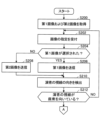
- FIG. 8 is a flow chart showing the operation of the processing device 306A.
- the flowchart of FIG. 8 shows image transmission processing for one terminal device 40-i.
- the processing device 306A performs the following processing in parallel for each of the terminal devices 40-1 to 40-7.
- the processing device 306A functions as the image acquisition unit 310 and acquires the first image PC1 from the first imaging device 10 and the second image PC2 from the second imaging device 20 (step S100). Acquisition of the first image PC1 and the second image PC2 continues during subsequent processing.
- the processing device 306A functions as a transmission control unit 316A and transmits the second image PC2 to the terminal device 40-i of the viewer Vi (step S102).
- the processing device 306A functions as the line-of-sight detection unit 312A, and detects the line-of-sight direction L of the performer P based on the second image PC2 (step S104).
- the processing device 306A functions as the movement control unit 314, and moves the first imaging device 10 on the line of sight of the performer P (step S106).
- the processing device 306A functions as the transmission control unit 316A, and determines whether or not the seat Ci is on the extension line of the line of sight of the performer P, that is, whether or not the line of sight of the performer P faces the seat Ci (step S108). ). If the line of sight of the performer P is not directed toward the seat Ci (step S108: NO), the processing device 306A returns the process to step S104.
- the processing device 306A When the line of sight of the performer P is directed toward the seat Ci (step S108: YES), the processing device 306A functions as the transmission control unit 316A and transmits the first image to the terminal device 40-i of the viewer Vi corresponding to the seat Ci. PC1 is transmitted (step S110). At this time, the processing device 306A may send an alert to the terminal device 40-i.
- the processing device 306A waits until the line of sight of the performer P leaves the seat Ci (step S112: NO). During this time, the first image PC1 is transmitted to the terminal device 40-i. When the actor P's line of sight moves away from the seat Ci (step S112: YES), the processing device 306A functions as the transmission control unit 316A, and transmits the second image PC2 to the terminal device 40-i of the viewer Vi corresponding to the seat Ci. It transmits (step S114). After that, the processing device 306A returns the processing to step S100.
- the image transmission system 1 when the line of sight of the performer P faces the virtually set seat Ci, the image of the performer P is captured from the seat Ci.
- One image PC1 is transmitted to the viewer Vi.
- the viewer Vi can also experience the experience that can occur at a real live venue, such as making eye contact with the performer P at the live venue, in viewing the online live performance. Therefore, the added value of online live is improved.
- a seat Ci is assigned to the viewer Vi who watches the online live. Therefore, the viewer Vi can view the first image PC1 that other viewers Vi+n (n is an arbitrary integer) cannot view, and can obtain the same experience as actually going to the live venue. .
- the image transmission system 1 when the image transmitted to the terminal device 40-i switches from the second image PC2 to the first image PC1, an alert is transmitted to the terminal device 40-i. Therefore, the viewer Vi is less likely to miss the first image PC1, and the degree of satisfaction with the online live performance is further improved.
- one first imaging device 10 moves between the plurality of seats C1 to C7 to capture the first image PC1. Therefore, the system cost of the image transmission system 1 is reduced compared to arranging a plurality of imaging devices.
- the line-of-sight direction L of the performer P is detected based on the second image PC2 captured by the second imaging device 20 . Therefore, the system cost of the image transmission system 1 is reduced as compared with the arrangement of an imaging device for tracking the line of sight of the performer P separately.
- FIG. 9 is a block diagram showing the configuration of an image transmission system 2 according to the second embodiment.
- the image transmission system 2 includes a plurality of first imaging devices 10-1 to 10-7, a second imaging device 20, and an image transmission device 30B.
- the image transmission device 30B is connected via a communication network N to a plurality of terminal devices 40 (40-1, 40-2 . . . 40-7). Since the second imaging device 20 and the terminal devices 40-1 to 40-7 are the same as in the first embodiment, description thereof will be omitted.
- FIG. 10 is an explanatory diagram schematically showing the arrangement of the first imaging devices 10-1 to 10-7 in the second embodiment.
- FIG. 10 is a view of Theater G viewed from above.
- the first imaging devices 10-1 to 10-7 are installed at the positions of seats C1 to C7 in the theater G, respectively.
- the respective first imaging devices 10-1 to 10-7 are fixed at the positions of the seats C1 to C7.
- the first imaging device 10-1 is fixed at the position of the seat C1
- the first imaging device 10-2 is fixed at the position of the seat C2.
- “fixed” means that the seat does not move in the theater G toward another seat Ci.
- the first imaging device 10-i may be capable of swinging such as panning and tilting, and moving up and down.
- the first imaging device 10-i captures an image of the stage S viewed from the seat Ci as a first image PC1-i.
- the imaging range of the first imaging device 10-i may be set, for example, to capture the entire stage S, or may be set to capture the face of the performer P in close-up.
- the first imaging device 10-i is preferably provided with an auxiliary mechanism for performing panning, tilting, zooming, etc. by remote control, for example. .
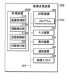
- FIG. 11 is a block diagram showing the configuration of the image transmission device 30B.
- the image transmission device 30B includes an input device 301, a display device 302, a communication device 303, an image input interface 304, a storage device 305, a processing device 306B, and a bus 307. Since the input device 301, the display device 302, the communication device 303, the image input interface 304, and the bus 307 are the same as those of the image transmission device 30A of the first embodiment, description thereof will be omitted.
- the storage device 305 stores the program PG2.
- the program PG2 is a program for operating the image transmission device 30B.
- the processing device 306B functions as an image acquisition unit 310, a line-of-sight detection unit 312B, a transmission control unit 316B, and a designation reception unit 320 by executing the program PG2.
- At least one of the image acquisition unit 310, line-of-sight detection unit 312B, transmission control unit 316B, and designation reception unit 320 may be configured by circuits such as DSP, ASIC, PLD, and FPGA.
- the image acquisition unit 310 functions in the same manner as in the first embodiment.
- the designation receiving unit 320 receives from the viewer Vi a designation as to whether the image to be transmitted to the terminal device 40-i is the first image PC1 or the second image PC2.
- one first imaging device 10 moves between the plurality of seats C1 to C7.
- the first imaging devices 10-1 to 10-7 are installed in the respective seats C1 to C7, and images of the stage S viewed from any seat Ci can always be obtained. be.
- the viewer Vi can appreciate the performance from the seat Ci associated with the viewer Vi.
- FIGS. 12A and 12B are explanatory diagrams showing examples of online live viewing screens on the terminal device 40-1.
- the terminal device 40-1 associated with the seat C1 will be described as an example of the terminal device 40-i.
- the terminal device 40-1 is, for example, a smart phone.
- FIG. 10 consider the case where the performer P faces seat C4.
- the display 400 of the terminal device 40-1 shows the whole body of the performer P captured from the front of the stage S as shown in FIG. 12A.
- the projected image is displayed.
- the display 400 also displays a first button B1 for image switching.
- the first button B1 is a button for switching the display to the first image PC1-1 captured by the first imaging device 10-1 installed on the seat C1 associated with the terminal device 40-1.
- the display 400 When the viewer V1 presses the first button B1, the display 400 displays the first image PC1-1 as shown in FIG. 12B. In the first image PC1-1, an image of the performer P whose line of sight is directed toward the seat C4 is captured from the seat C1.
- the display 400 also displays a second button B2 for image switching.
- the second button B ⁇ b>2 is a button for switching the display to the second image PC ⁇ b>2 captured by the second imaging device 20 .
- the display 400 displays the second image PC2 as shown in FIG. 12A.
- the line-of-sight detection unit 312B detects the line-of-sight direction L of the performer P.
- the line-of-sight detection unit 312B is an example of a detection unit.
- the line-of-sight detection unit 312B detects the line-of-sight direction L of the performer P based on the first image PC1.
- the line-of-sight detection unit 312B detects the position of the performer P on the stage S and the face orientation of the performer P by a method of performing image analysis on each of the first images PC1-1 to PC1-7.
- the line-of-sight detection unit 31 estimates that the line-of-sight of the performer P is directed toward the first imaging device 10-i capturing an image in which the face of the performer P faces the front, for example.
- the line-of-sight detection unit 312B may further detect the position of the iris of the performer P from the first images PC1-1 to PC1-7 to detect the line-of-sight direction L of the performer P in more detail.
- the line-of-sight direction L of the performer P may be detected based on the second image PC2.
- the transmission control unit 316B transmits the captured image of the performer P to the terminal devices 40-1 to 40-7.
- the image obtained by imaging the performer P is the first image PC1 or the second image PC2.
- the transmission control unit 316B switches the image to be transmitted to the terminal devices 40-1 to 40-7 between the first image PC1 and the second image PC2 based on the designation result received by the designation receiving unit 320.
- the transmission control unit 316B normally transmits to the terminal device 40-i the image specified by the viewer Vi, either the first image PC1 or the second image PC2.
- the normal time is when the line-of-sight direction L of the performer P is not facing the seat Ci associated with the terminal device 40-i.
- the transmission control unit 316B controls the terminal device 40-i regardless of the designation made by the viewer Vi. to transmit the first image PC1-i.
- FIG. 13 is an explanatory diagram schematically showing switching of transmission images performed by the transmission control unit 316B.
- FIG. 13 shows an image transmitted to the terminal device 40-1, for example. Below, the case where the performer P looks at the seat C1 associated with the terminal device 40-1 from time t11 to t12 will be considered.
- the transmission control unit 316B transmits the second image PC2 to the terminal device 40-1 until time t11.
- the transmission control unit 316B transmits the first image PC1-1 to the terminal device 40-1 from time t11 to t12 when the line of sight of the performer P is directed toward the seat C1.
- the transmission control unit 316B may transmit an alert (symbol N in the drawing) before the display image on the terminal device 40-1 is switched to the first image PC1-1.
- the transmission control unit 316B returns the image to be transmitted to the terminal device 40-1 to the second image PC2 after time t12 when the line of sight of the performer P is removed from the seat C1.
- the transmission control unit 316B has transmitted the first image PC1-1 to the terminal device 40-1 at time t11.
- the transmission control unit 316B also continues to transmit the first image PC1-1 to the terminal device 40-1 during the period from time t11 to t12 when the line of sight of the performer P is directed toward the seat C1.
- the transmission control unit 316B also transmits the first image PC1-1 to the terminal device 40-1 after time t12 when the line of sight of the performer P leaves the seat C1.
- the transmission control unit 316B transmits an alert to the terminal device 40-1 before the time t11 when the line of sight of the performer P faces the seat C1 (symbol N in the figure). Therefore, the viewer V1 can recognize that the line of sight of the performer P is directed to the seat C1, and can prevent overlooking the image of the camera line of sight.
- FIGS. 14 and 14B are flow charts showing the operation of processing unit 306B. In the flowcharts of FIGS. 14 and 14B, for convenience of explanation, attention is paid to image transmission to one terminal device 40-i.
- the processing device 306B performs the following processing in parallel for each of the terminal devices 40-1 to 40-7.
- the processing device 306B functions as the image acquisition unit 310 and acquires the first image PC1 from the first imaging device 10 and the second image PC2 from the second imaging device 20 (step S200). Acquisition of the first image PC1 and the second image PC2 continues during subsequent processing.
- the processing device 306B functions as the designation reception unit 320, and receives designation of whether the image to be transmitted from the viewer Vi to the terminal device 40-i is the first image PC1 or the second image PC2 (step S202). .
- the processing device 306B functions as the transmission control unit 316B and transmits the first image PC1 to the terminal device 40-i (step S206).
- the processing device 306B functions as the transmission control unit 316B and transmits the second image PC1 to the terminal device 40.
- PC2 is transmitted (step S208).
- the processing device 306B functions as the line-of-sight detection unit 312B, and detects the line-of-sight direction L of the performer P based on the first image PC1 (step S210).
- the processing device 306B functions as the transmission control unit 316B, and determines whether the seat Ci is on an extension of the line of sight of the performer P, that is, whether the line of sight of the performer P faces the seat Ci (step S212). If the line of sight of the performer P is not directed toward the seat Ci (step S212: NO), the processing device 306B returns the process to step S202.
- the processing device 306B When the line of sight of the performer P is directed toward the seat Ci (step S212: YES), the processing device 306B functions as the transmission control unit 316B, and transmits to the terminal device 40-i corresponding to the seat Ci. It is determined whether or not it is two-image PC2 (step S214). If the image being transmitted to the terminal device 40-i is the second image PC2 (step S214: YES), the processing device 306B transmits the first image PC1 to the terminal device 40-i (step S216). That is, the image to be transmitted to the terminal device 40-i is switched from the second image PC2 to the first image PC1. At this time, the processing device 306B may send an alert to the terminal device 40-i.
- the processing device 306B waits until the line of sight of the performer P is removed from the seat Ci (step S218: NO). During this time, the first image PC1 is transmitted to the terminal device 40-i. When the line of sight of the performer P leaves the seat Ci (step S218: YES), the processing device 306B functions as the transmission control unit 316B and transmits the second image PC2 to the terminal device 40-i (step S220). After that, the processing device 306B returns the processing to step S200.
- step S214 if the image being transmitted to the terminal device 40-i is not the second image PC2 (step S214: NO), that is, in the case of the first image PC1, the processing device 306B sends the terminal device 40-i An alert is sent to i (step S222). After that, the processing device 306B returns the processing to step S200.
- the first imaging devices 10-1 to 10-7 are arranged corresponding to the respective seats C1 to C7. Therefore, the viewer Vi can view the captured image (first image PC1-i) from the seat Ci associated with the viewer Vi at any timing, and can obtain a viewing experience close to an actual live performance. .
- the first imaging devices 10-1 to 10-7 are arranged corresponding to the respective seats C1 to C7, it is possible to more reliably capture an image in which the line of sight of the performer P is directed. . Therefore, the degree of satisfaction of the viewers Vi with respect to the online live performance is improved.
- the gaze direction L of the performer P is detected based on the first images PC1-1 to PC1-7 captured by the first imaging devices 10-1 to 10-7. Therefore, the line-of-sight direction L of the performer P can be detected more accurately than when the line-of-sight of the performer P is tracked based on an image captured by a single imaging device.
- the first modification employs the configuration of the second embodiment shown in FIGS.
- the case where there is one performer P has been described.
- the performers P are members of a band, group, or the like
- a plurality of performers P may appear on the stage S.
- one of the performers P's line of sight may frequently be directed toward the seat Ci.
- the viewer Vi may be interested only in a specific member out of a plurality of members. That is, if the above-described control is performed on all of the plurality of performers P, it may become difficult to watch the performance, or the degree of satisfaction of the viewers Vi may decrease.
- the viewer Vi may be allowed to specify the performer P to switch to the first image PC1 when looking at the seat Ci.
- a first performer P1 and a second performer P2 performing together with the first performer P1 are on stage S.
- the image transmission device 30B shown in FIG. 11 receives the designation of the first performer P1 or the second performer P2 from the viewer Vi by the designation reception unit 320.
- FIG. The designation reception unit 320 is an example of a reception unit.
- the line-of-sight detection unit 312B detects the line-of-sight direction L of the first performer P1 and the line-of-sight direction L of the second performer P1.
- the transmission control unit 316B transmits the first image PC1 to the terminal device 40-i based on the fact that the first performer P1 is designated by the viewer Vi and the line of sight of the first performer P1 is directed toward the seat Ci.
- the transmission control unit 316B transmits the first image PC1 to the terminal device 40-i based on the fact that the viewer Vi designates the second performer P2 and the line of sight of the second performer P2 is directed toward the virtual seat Ci. Send,
- the transmission control unit 316B sends the image to be transmitted to the terminal device 40-i to the first Switch to image PC1.
- the transmission control unit 316B does not switch the image to be transmitted to the terminal device 40-i.
- switching to the first image PC1 is performed only when the performer P specified by the viewer Vi turns his or her line of sight toward the seat Ci. Therefore, it is possible to prevent the image transmitted to the terminal device 40-i from being frequently switched. In addition, the viewer Vi can watch the performance of the performer P to watch without missing it.
- the configuration of the second embodiment is used in the first modification, for example, when there is only one viewer Vi, or when all viewers Vi designate the same performer P (for example, the first performer P1) In some cases, the configuration of the first embodiment may be used.
- the transmission control unit 316A switches the image to be transmitted to the terminal device 40-i to the first image PC1 at the timing when the line of sight of the performer P faces the seat Ci.
- the present invention is not limited to this, and may be switched to the first image PC1 before the line of sight of the performer P turns to the seat Ci.
- FIG. 15 is an explanatory diagram schematically showing the second modified example.
- illustration of the first imaging device 10 and the second imaging device 20 is omitted.
- Image switching ranges H1 to H7 are set for the seats C1 to C7, respectively.
- the width of the image switching range H1 to H7 is set wider to the left and right than the range of the seats C1 to C7.
- the image switching range H1 to H7 is set to be wider than the range of the seats C1 to C7, so transmission of the first image PC1 to the terminal device 40-1 is started at , earlier than when the performer P turns to the seat C1.
- the transmission of the first image PC1 to the terminal device 40-1 ends after a certain amount of time has passed since the line of sight of the performer P left the seat C1. For example, as shown in FIG. 15, when the performer P is looking at the overlapping range of the image switching ranges H3 and H4, the terminal device 40-3 corresponding to the seat C3 and the terminal device 40- corresponding to the seat C4 4, the first image PC1 is transmitted.
- the viewer Vi can see how the performer P turns his/her eyes to the seat Ci corresponding to him/herself, and can more realistically experience the sensation of making eye contact with the performer P.
- the line-of-sight direction L of the performer P is detected based on the first image PC1 captured by the first imaging device 10 or the second image PC2 captured by the second imaging device 20.
- a third imaging device that captures an image for detecting the line-of-sight direction L of the performer P may be provided.
- the third imaging device may be, for example, an imaging device arranged closer to the stage S than the first imaging device 10 .
- the third imaging device may be, for example, an imaging device mounted on XR (Extended Reality) glasses that the performer P wears during the performance.
- the third imaging device may be, for example, an imaging device mounted on an eye tracking device specialized for tracking the performer P's line of sight.
- the direction L of the line of sight of the performer P is detected based on the image specialized for detecting the direction L of the line of sight of the performer P, the direction L of the line of sight of the performer P can be detected more accurately. well detected.
- the first imaging device 10 or the second imaging device 20 does not always have to image the performer P, for example, it is possible to image other than the performer P according to the performance during the performance, and the online live visual The degree of freedom of expression can be improved.
- the line-of-sight direction L of the performer P may be calculated based on the detected value of a sensor attached to the head of the performer P.
- the sensor in this case can be, for example, an inertial measurement unit (IMU) or a geomagnetic sensor.
- the processing load on the processing device 306A or 306B can be reduced compared to performing image processing.
- Each function illustrated in FIGS. 5 and 11 is realized by any combination of hardware and software.
- a method for realizing each function is not particularly limited.
- Each function may be implemented using one device physically or logically coupled, or two or more devices physically or logically separated, directly or indirectly (e.g., wired, It may also be implemented using devices that are configured by connecting (eg, wirelessly).
- Each function may be implemented by combining software in the one device or the plurality of devices.
- apparatus may be read as other terms such as circuits, devices or units.
- the storage device 305 includes an optical disk such as a CD-ROM (Compact Disc ROM), a hard disk drive, a flexible disk, an optical Magnetic discs (e.g. compact discs, digital versatile discs, Blu-ray discs), smart cards, flash memory (e.g. cards, sticks, key drives), floppy discs, magnetic strips, etc. It may be configured by at least one. Also, the program may be transmitted from a network via an electric communication line.
- a CD-ROM Compact Disc ROM
- a hard disk drive e.g. compact discs, digital versatile discs, Blu-ray discs
- an optical Magnetic discs e.g. compact discs, digital versatile discs, Blu-ray discs
- smart cards e.g. cards, sticks, key drives
- flash memory e.g. cards, sticks, key drives
- floppy discs e.g. cards, sticks, key drives
- Each of the first embodiment, second embodiment, first to third modifications is LTE (Long Term Evolution), LTE-A (LTA-Advanced), SUPER 3G, IMT-Advanced, 4G (4th generation mobile communication system), 5G (5th generation mobile communication system), 6th generation mobile communication system (6G), xth generation mobile communication system nication system (xG) (x is, for example, an integer or a decimal number), FRA (Future Radio Access) , NR (new Radio), New radio access (NX), Future generation radio access (FX), W-CDMA (registered trademark), GSM (registered trademark), CDMA2000, UMB (Ultra Mobile Broadband), IEEE 802.11 ( Wi-Fi (registered trademark)), IEEE 802.16 (WiMAX (registered trademark)), IEEE 802.20, UWB (Ultra-WideBand), Bluetooth (registered trademark), other suitable systems and systems utilizing these may be applied to at least one of the next generation systems that are extended, modified, created, defined
- input/output information may be stored in a specific location (for example, memory) or may be managed. It may be managed using a table. Input/output information and the like may be overwritten, updated, or appended. The output information and the like may be deleted. The entered information and the like may be transmitted to another device.
- a specific location for example, memory
- Input/output information and the like may be overwritten, updated, or appended.
- the output information and the like may be deleted.
- the entered information and the like may be transmitted to another device.
- the determination may be made based on the value (0 or 1) represented by one bit. However, it may be performed based on a true/false value (Boolean: true or false), or may be performed based on numerical comparison (for example, comparison with a predetermined value).
- the programs exemplified in each of the first embodiment, second embodiment, and first to third modifications are referred to as software, firmware, middleware, microcode, hardware description language, or other names.
- instruction, instruction set, code, code segment, program code, subprogram, software module, application, software application, software package, routine, subroutine, object, executable file, thread of execution, procedure or function, whether called by should be interpreted broadly to mean Software, instructions, etc. may also be transmitted and received over a transmission medium.
- the software uses wired technology (coaxial cable, fiber optic cable, twisted pair and digital subscriber line (DSL), etc.) and/or wireless technology (infrared, microwave, etc.) to access websites, servers, or other When transmitted from a remote source, these wired and/or wireless technologies are included within the definition of transmission media.
- wired technology coaxial cable, fiber optic cable, twisted pair and digital subscriber line (DSL), etc.
- wireless technology infrared, microwave, etc.
- the terminal device 40 may be a mobile station.
- a mobile station is defined by those skilled in the art as subscriber station, mobile unit, subscriber unit, wireless unit, remote unit, mobile device, wireless device, wireless communication device, remote device, mobile subscriber station, access terminal, mobile terminal, wireless It may also be referred to as a terminal, remote terminal, handset, user agent, mobile client, client or some other suitable terminology.
- a mobile station may be called a transmitting device, a receiving device, a communication device, or the like.
- a mobile station may be a device mounted on a mobile, or the mobile itself, or the like.
- a moving object means an object that can move. The moving speed of the moving body is arbitrary. The moving object can be stopped.
- Mobile bodies include, for example, vehicles, transport vehicles, automobiles, motorcycles, bicycles, connected cars, excavators, bulldozers, wheel loaders, dump trucks, forklifts, trains, buses, carts, rickshaws, ships (ship and other watercraft), Including, but not limited to, airplanes, rockets, satellites, drones, multicopters, quadcopters, balloons, and anything mounted thereon.
- the mobile body may be a mobile body that autonomously travels based on an operation command.
- the mobile object may be a vehicle (e.g., car, airplane, etc.), an unmanned mobile object (e.g., drone, self-driving car, etc.), or a robot (manned or unmanned).
- vehicle e.g., car, airplane, etc.
- unmanned mobile object e.g., drone, self-driving car, etc.
- a robot manned or unmanned.
- Mobile stations also include devices that are not necessarily mobile during communication operations.
- the mobile station may be an IoT (Internet of Things) device such as a sensor.
- the term “determining” or “determining” encompasses a wide variety of actions.
- “Determination” includes, for example, judging, calculating, computing, processing, deriving, investigating, looking up, searching, inquiry (e.g., table , searching in a database or other data structure), ascertaining what has been “determined”, and the like.
- “determining” includes receiving (e.g., receiving information), transmitting (e.g., transmitting information), input, output, accessing ( For example, access to data in memory) may be considered to be a "judgment” or “decision”.
- “determining” may include considering resolving, selecting, choosing, establishing, comparing, etc. to be “determined.” That is, “determining” may include deeming some action "determined”. Also, “determination” may be read as “assuming", “expecting", “considering”, or the like.
- connection refers to two or more elements means any direct or indirect connection or coupling between, and may include the presence of one or more intermediate elements between two elements that are “connected” or “coupled” to each other. Couplings or connections between elements may be physical, logical, or a combination thereof. For example, “connection” may be read as "access”.
- two elements are defined using at least one of one or more wires, cables, and printed electrical connections and, as some non-limiting and non-exhaustive examples, in the radio frequency domain. , electromagnetic energy having wavelengths in the microwave and light (both visible and invisible) regions, and the like.
Landscapes
- Engineering & Computer Science (AREA)
- Theoretical Computer Science (AREA)
- Physics & Mathematics (AREA)
- General Physics & Mathematics (AREA)
- General Engineering & Computer Science (AREA)
- Human Computer Interaction (AREA)
- Databases & Information Systems (AREA)
- Signal Processing (AREA)
- Multimedia (AREA)
- Computer Vision & Pattern Recognition (AREA)
- Astronomy & Astrophysics (AREA)
- Computer Graphics (AREA)
- Two-Way Televisions, Distribution Of Moving Picture Or The Like (AREA)
- Studio Devices (AREA)
Priority Applications (2)
| Application Number | Priority Date | Filing Date | Title |
|---|---|---|---|
| US18/723,898 US20250181293A1 (en) | 2022-01-07 | 2022-11-16 | Image transmission system and image transmission apparatus |
| JP2023572363A JP7688162B2 (ja) | 2022-01-07 | 2022-11-16 | 画像送信システムおよび画像送信装置 |
Applications Claiming Priority (2)
| Application Number | Priority Date | Filing Date | Title |
|---|---|---|---|
| JP2022001394 | 2022-01-07 | ||
| JP2022-001394 | 2022-01-07 |
Publications (1)
| Publication Number | Publication Date |
|---|---|
| WO2023132132A1 true WO2023132132A1 (ja) | 2023-07-13 |
Family
ID=87073638
Family Applications (1)
| Application Number | Title | Priority Date | Filing Date |
|---|---|---|---|
| PCT/JP2022/042547 Ceased WO2023132132A1 (ja) | 2022-01-07 | 2022-11-16 | 画像送信システムおよび画像送信装置 |
Country Status (3)
| Country | Link |
|---|---|
| US (1) | US20250181293A1 (https=) |
| JP (1) | JP7688162B2 (https=) |
| WO (1) | WO2023132132A1 (https=) |
Citations (2)
| Publication number | Priority date | Publication date | Assignee | Title |
|---|---|---|---|---|
| JP2018505584A (ja) * | 2014-12-23 | 2018-02-22 | インテル コーポレイション | インタラクティブ双眼鏡ビデオ表示 |
| WO2021246498A1 (ja) * | 2020-06-03 | 2021-12-09 | エイベックス・テクノロジーズ株式会社 | ライブ配信システム |
Family Cites Families (10)
| Publication number | Priority date | Publication date | Assignee | Title |
|---|---|---|---|---|
| US9268406B2 (en) * | 2011-09-30 | 2016-02-23 | Microsoft Technology Licensing, Llc | Virtual spectator experience with a personal audio/visual apparatus |
| EP2582145A3 (en) * | 2011-10-13 | 2014-07-30 | Gface GmbH | Interactive remote participation in live entertainment |
| US10602133B2 (en) * | 2016-10-04 | 2020-03-24 | Facebook, Inc. | Controls and interfaces for user interactions in virtual spaces |
| US20180095635A1 (en) * | 2016-10-04 | 2018-04-05 | Facebook, Inc. | Controls and Interfaces for User Interactions in Virtual Spaces |
| US20190358547A1 (en) * | 2016-11-14 | 2019-11-28 | Lightcraft Technology Llc | Spectator virtual reality system |
| US10445941B2 (en) * | 2017-06-21 | 2019-10-15 | Number 9, LLC | Interactive mixed reality system for a real-world event |
| US10341537B2 (en) * | 2017-09-29 | 2019-07-02 | Sony Interactive Entertainment America Llc | Spectator view into an interactive gaming world showcased in a live event held in a real-world venue |
| US11058950B2 (en) * | 2019-03-15 | 2021-07-13 | Sony Interactive Entertainment Inc. | Methods and systems for spectating characters in virtual reality views |
| US11050977B2 (en) * | 2019-06-18 | 2021-06-29 | Tmrw Foundation Ip & Holding Sarl | Immersive interactive remote participation in live entertainment |
| US11418760B1 (en) * | 2021-01-29 | 2022-08-16 | Microsoft Technology Licensing, Llc | Visual indicators for providing user awareness of independent activity of participants of a communication session |
-
2022
- 2022-11-16 JP JP2023572363A patent/JP7688162B2/ja active Active
- 2022-11-16 US US18/723,898 patent/US20250181293A1/en active Pending
- 2022-11-16 WO PCT/JP2022/042547 patent/WO2023132132A1/ja not_active Ceased
Patent Citations (2)
| Publication number | Priority date | Publication date | Assignee | Title |
|---|---|---|---|---|
| JP2018505584A (ja) * | 2014-12-23 | 2018-02-22 | インテル コーポレイション | インタラクティブ双眼鏡ビデオ表示 |
| WO2021246498A1 (ja) * | 2020-06-03 | 2021-12-09 | エイベックス・テクノロジーズ株式会社 | ライブ配信システム |
Also Published As
| Publication number | Publication date |
|---|---|
| JPWO2023132132A1 (https=) | 2023-07-13 |
| US20250181293A1 (en) | 2025-06-05 |
| JP7688162B2 (ja) | 2025-06-03 |
Similar Documents
| Publication | Publication Date | Title |
|---|---|---|
| JP7770366B2 (ja) | Dmvrおよびbdofベースのインター予測方法および装置 | |
| US11265603B2 (en) | Information processing apparatus and method, display control apparatus and method, reproducing apparatus and method, and information processing system | |
| US20210389847A1 (en) | Information Processing Device and Information Processing Method | |
| US10893329B1 (en) | Dynamic occlusion of livestreaming | |
| CN107615758A (zh) | 跟踪辅助装置、跟踪辅助系统以及跟踪辅助方法 | |
| US11703942B2 (en) | System and method for interactive 360 video playback based on user location | |
| US20160070346A1 (en) | Multi vantage point player with wearable display | |
| US11657574B2 (en) | Systems and methods for providing an audio-guided virtual reality tour | |
| JPWO2017169369A1 (ja) | 情報処理装置、情報処理方法、プログラム | |
| US20150319402A1 (en) | Providing video recording support in a co-operative group | |
| US12153777B2 (en) | System and method utilizing multiple virtual presence devices | |
| US10448063B2 (en) | System and method for perspective switching during video access | |
| US12568282B2 (en) | Content display method, apparatus, device and medium | |
| WO2023132132A1 (ja) | 画像送信システムおよび画像送信装置 | |
| WO2021181202A1 (en) | System, method, and computer program for generating volumetric video | |
| EP3190503A1 (en) | An apparatus and associated methods | |
| JP4632362B2 (ja) | 情報出力システム、情報出力方法およびプログラム | |
| KR20140130330A (ko) | 착용형 전자 장치 및 그의 제어 방법 | |
| CN107404661A (zh) | 一种微电影视频获取方法及装置 | |
| CN112612435A (zh) | 信息处理方法、装置、设备及存储介质 | |
| US20250383593A1 (en) | Projection device and method of operating the same | |
| US12211360B2 (en) | Navigable 3D view of a premises alarm event | |
| CN119583862B (zh) | 一种信息展示方法、装置、存储介质及电子设备 | |
| CN118590667A (zh) | 投屏方法、装置、设备及存储介质 | |
| Leonardi | Distributed Video Coding: Identifying Promising Application Scenarios |
Legal Events
| Date | Code | Title | Description |
|---|---|---|---|
| 121 | Ep: the epo has been informed by wipo that ep was designated in this application |
Ref document number: 22918721 Country of ref document: EP Kind code of ref document: A1 |
|
| ENP | Entry into the national phase |
Ref document number: 2023572363 Country of ref document: JP Kind code of ref document: A |
|
| NENP | Non-entry into the national phase |
Ref country code: DE |
|
| 122 | Ep: pct application non-entry in european phase |
Ref document number: 22918721 Country of ref document: EP Kind code of ref document: A1 |
|
| WWP | Wipo information: published in national office |
Ref document number: 18723898 Country of ref document: US |