WO2023127579A1 - Lamp unit for vehicular headlamp, and vehicular headlamp - Google Patents
Lamp unit for vehicular headlamp, and vehicular headlamp Download PDFInfo
- Publication number
- WO2023127579A1 WO2023127579A1 PCT/JP2022/046712 JP2022046712W WO2023127579A1 WO 2023127579 A1 WO2023127579 A1 WO 2023127579A1 JP 2022046712 W JP2022046712 W JP 2022046712W WO 2023127579 A1 WO2023127579 A1 WO 2023127579A1
- Authority
- WO
- WIPO (PCT)
- Prior art keywords
- light
- vehicle
- light distribution
- lens
- distribution pattern
- Prior art date
Links
Images


Classifications
-
- F—MECHANICAL ENGINEERING; LIGHTING; HEATING; WEAPONS; BLASTING
- F21—LIGHTING
- F21S—NON-PORTABLE LIGHTING DEVICES; SYSTEMS THEREOF; VEHICLE LIGHTING DEVICES SPECIALLY ADAPTED FOR VEHICLE EXTERIORS
- F21S41/00—Illuminating devices specially adapted for vehicle exteriors, e.g. headlamps
- F21S41/10—Illuminating devices specially adapted for vehicle exteriors, e.g. headlamps characterised by the light source
- F21S41/14—Illuminating devices specially adapted for vehicle exteriors, e.g. headlamps characterised by the light source characterised by the type of light source
- F21S41/141—Light emitting diodes [LED]
- F21S41/143—Light emitting diodes [LED] the main emission direction of the LED being parallel to the optical axis of the illuminating device
-
- F—MECHANICAL ENGINEERING; LIGHTING; HEATING; WEAPONS; BLASTING
- F21—LIGHTING
- F21S—NON-PORTABLE LIGHTING DEVICES; SYSTEMS THEREOF; VEHICLE LIGHTING DEVICES SPECIALLY ADAPTED FOR VEHICLE EXTERIORS
- F21S41/00—Illuminating devices specially adapted for vehicle exteriors, e.g. headlamps
- F21S41/30—Illuminating devices specially adapted for vehicle exteriors, e.g. headlamps characterised by reflectors
- F21S41/32—Optical layout thereof
- F21S41/36—Combinations of two or more separate reflectors
-
- F—MECHANICAL ENGINEERING; LIGHTING; HEATING; WEAPONS; BLASTING
- F21—LIGHTING
- F21S—NON-PORTABLE LIGHTING DEVICES; SYSTEMS THEREOF; VEHICLE LIGHTING DEVICES SPECIALLY ADAPTED FOR VEHICLE EXTERIORS
- F21S41/00—Illuminating devices specially adapted for vehicle exteriors, e.g. headlamps
- F21S41/60—Illuminating devices specially adapted for vehicle exteriors, e.g. headlamps characterised by a variable light distribution
- F21S41/65—Illuminating devices specially adapted for vehicle exteriors, e.g. headlamps characterised by a variable light distribution by acting on light sources
- F21S41/663—Illuminating devices specially adapted for vehicle exteriors, e.g. headlamps characterised by a variable light distribution by acting on light sources by switching light sources
-
- F—MECHANICAL ENGINEERING; LIGHTING; HEATING; WEAPONS; BLASTING
- F21—LIGHTING
- F21V—FUNCTIONAL FEATURES OR DETAILS OF LIGHTING DEVICES OR SYSTEMS THEREOF; STRUCTURAL COMBINATIONS OF LIGHTING DEVICES WITH OTHER ARTICLES, NOT OTHERWISE PROVIDED FOR
- F21V7/00—Reflectors for light sources
- F21V7/04—Optical design
- F21V7/08—Optical design with elliptical curvature
-
- F—MECHANICAL ENGINEERING; LIGHTING; HEATING; WEAPONS; BLASTING
- F21—LIGHTING
- F21V—FUNCTIONAL FEATURES OR DETAILS OF LIGHTING DEVICES OR SYSTEMS THEREOF; STRUCTURAL COMBINATIONS OF LIGHTING DEVICES WITH OTHER ARTICLES, NOT OTHERWISE PROVIDED FOR
- F21V7/00—Reflectors for light sources
- F21V7/04—Optical design
- F21V7/09—Optical design with a combination of different curvatures
-
- F—MECHANICAL ENGINEERING; LIGHTING; HEATING; WEAPONS; BLASTING
- F21—LIGHTING
- F21W—INDEXING SCHEME ASSOCIATED WITH SUBCLASSES F21K, F21L, F21S and F21V, RELATING TO USES OR APPLICATIONS OF LIGHTING DEVICES OR SYSTEMS
- F21W2102/00—Exterior vehicle lighting devices for illuminating purposes
- F21W2102/10—Arrangement or contour of the emitted light
- F21W2102/13—Arrangement or contour of the emitted light for high-beam region or low-beam region
- F21W2102/135—Arrangement or contour of the emitted light for high-beam region or low-beam region the light having cut-off lines, i.e. clear borderlines between emitted regions and dark regions
- F21W2102/14—Arrangement or contour of the emitted light for high-beam region or low-beam region the light having cut-off lines, i.e. clear borderlines between emitted regions and dark regions having vertical cut-off lines; specially adapted for adaptive high beams, i.e. wherein the beam is broader but avoids glaring other road users
- F21W2102/145—Arrangement or contour of the emitted light for high-beam region or low-beam region the light having cut-off lines, i.e. clear borderlines between emitted regions and dark regions having vertical cut-off lines; specially adapted for adaptive high beams, i.e. wherein the beam is broader but avoids glaring other road users wherein the light is emitted between two parallel vertical cutoff lines, e.g. selectively emitted rectangular-shaped high beam
-
- F—MECHANICAL ENGINEERING; LIGHTING; HEATING; WEAPONS; BLASTING
- F21—LIGHTING
- F21Y—INDEXING SCHEME ASSOCIATED WITH SUBCLASSES F21K, F21L, F21S and F21V, RELATING TO THE FORM OR THE KIND OF THE LIGHT SOURCES OR OF THE COLOUR OF THE LIGHT EMITTED
- F21Y2115/00—Light-generating elements of semiconductor light sources
- F21Y2115/10—Light-emitting diodes [LED]
Definitions
- a lamp unit for a vehicle headlamp includes an outer reflecting surface provided outside the vehicle from the plurality of light emitting elements, and the outer reflecting surface receives light emitted from the outermost light emitting element located on the outermost side of the vehicle. Light is reflected as reflected light on the lens, and the lens projects the reflected light from the outer reflecting surface forward of the vehicle so as to add it as an additional light distribution pattern to the innermost partial light distribution pattern located on the innermost side of the vehicle. It is preferable to let it emit.
- FIG. 1R (Description of right lamp unit 1R)
- the vehicle outer side is the right side of the vehicle V
- the vehicle inner side is the left side of the vehicle V. called “left side”.
- the vehicle outer side is the left side of the vehicle V
- the vehicle inner side is the right side of the vehicle V. ”.
- the lamp unit 1R includes a light source 2, a reflector 3, a lens 4, a heat sink 5, and a fan unit 6.
- the light source 2, reflector 3, lens 4, heat sink 5, and fan unit 6 are attached to a frame member (not shown) and attached to the lamp housing 101 via the frame member and bracket member (not shown). It is
- the front shape of the lens 4 (the front shape of the output surface 41) is a horizontally long shape with a narrow vertical width (vertical width) and a wide horizontal width (horizontal width). Also, the thickness of the lens 4 is thick at the central portion and gradually decreases from the central portion to the peripheral portion. Furthermore, the radius of curvature of the entrance surface 40 is greater than the radius of curvature of the exit surface 41 . That is, the lens 4 of the ADB type lamp units 1L and 1R needs to let the light from the ten light emitting elements LED1 to LED10 enter from the entrance surface 40 and irradiate the vehicle V forward from the exit surface 41. . Therefore, the radius of curvature of the entrance surface 40 is large, and the radius of curvature of the exit surface 41 is small.
- the vehicle outer edge of the first partial light distribution patterns PL1A and PR1A on which the diffuse light distribution patterns PL1C and PR1C are superimposed (hereinafter referred to as "first partial light distribution patterns PL1A and PR1A after superimposition")
- the vehicle-outside vertical cutoff line CL1RC (see FIGS. 5A and 9B) is the first partial light distribution patterns PL1 and PR1 (hereinafter referred to as the first partial light distribution patterns PL1 and PR1 on which the diffuse light distribution patterns PL1C and PR1C are not superimposed).
- first partial light distribution patterns PL1 and PR1 before superimposition in this example, the vehicle outside vertical cutoff line CL1R (see FIGS. 5(B) and 9(B)). Located outside (on the right).
- the vertical cut-off line CL1L (see FIGS. 5A and 9B) of the first partial light distribution patterns PL1A and PR1A after superimposition and the first partial light distribution patterns PL1 and PR1 before superimposition is the same or substantially the same as the vehicle inner longitudinal cut-off line CL1L (see FIGS. 5(B) and 9(B)).
- the extinguished left side The left partial light distribution patterns PL5 to PL8 and the right partial light distribution patterns PR5 to PR8 corresponding to the light emitting elements LED5 to LED8 of the lamp unit 1L and the light emitting elements LED5 to LED8 of the right lamp unit 1R, respectively, As shown by the dashed line in FIG. 12, it disappears or the luminosity decreases. As a result, in the overall high beam light distribution pattern P shown in FIG. 12, the area where the preceding vehicle V2 exists becomes darker than the surrounding areas, and the preceding vehicle V2 is not dazzled.
- the lamp systems 1L, 1R, 100L, and 100R transmit light from the ten light emitting elements LED1 to LED10 through a lens 4 arranged in front of a light source 2 having ten light emitting elements LED1 to LED10.
- 10 partial light distribution patterns PL1 to PL10 and PR1 to PR10 arranged in the horizontal direction in the front direction of the vehicle V.
- the lamp systems 1L, 1R, 100L, and 100R reflect the light L2 from the second light emitting element LED2 located next to the first light emitting element LED1 as the reflected light L21 outside the lens 4 by the inner reflecting surface 30L. is. Therefore, in the lamp systems 1L, 1R, 100L, and 100R, the reflected light L21 from the inner reflecting surface 30L does not pass through the lens 4 to form a light distribution pattern. There is no influence on the 10 partial light distribution patterns PL1 to PL10 and PR1 to PR10.
Abstract
The objective of the present invention is to provide a lamp unit for a vehicular headlamp, and a vehicular headlamp, capable of causing both the left and right edges of a high-beam light distribution pattern to be further diffused to the left and right. Light (L1) from a first light emitting element (LED1) is reflected as reflected light (L11) onto a lens (4) by means of an inner reflecting surface (30L). The reflected light (L11) is emitted as a diffused light distribution pattern (PL1C, PR1C) toward the front of a vehicle (V) by the lens (4). Edges of the diffused light distribution pattern (PL1C, PR1C) on a vehicle outer side are positioned farther to the vehicle outer side than edges of a first partial light distribution pattern (PL1, PR1) on the vehicle outer side. As a result, both the left and right edges of an overall high-beam light distribution pattern (P) can be further diffused to the left and right.
Description
この発明は、車両用前照灯(ヘッドランプ)のランプユニットに関するものである。また、車両用前照灯(ヘッドランプ)に関するものである。
The present invention relates to a lamp unit for vehicle headlights (headlamps). It also relates to vehicle headlights (headlamps).
ハイビーム配光パターン(走行ビーム配光パターン)を対向車や先行車などの前方車両に応じて変化させる配光可変タイプのランプユニット、いわゆる、ADB(Adaptive Driving Beam)タイプのランプユニット、および、そのランプユニットを備える車両用前照灯としては、たとえば、下記の特許文献1および特許文献2に示すものがある。以下、特許文献1および特許文献2について説明する。
A variable light distribution type lamp unit that changes the high beam light distribution pattern (running beam light distribution pattern) according to the oncoming vehicle or preceding vehicle, etc., so-called ADB (Adaptive Driving Beam) type lamp unit, and its Vehicle headlamps having a lamp unit are disclosed, for example, in Patent Document 1 and Patent Document 2 below. Patent document 1 and patent document 2 are described below.
特許文献1の車両用灯具ユニットは、投影レンズと、光源ユニットと、を備え、光源ユニットは、水平方向に一列に配置されていて、内周面に反射面が形成された複数の筒部と、複数の筒部の一端の入射口にそれぞれ配置されている複数の半導体発光素子と、を備える。
The vehicle lighting unit disclosed in Patent Document 1 includes a projection lens and a light source unit. The light source unit is horizontally arranged in a line and includes a plurality of cylindrical portions each having a reflecting surface formed on its inner peripheral surface. and a plurality of semiconductor light emitting elements respectively arranged at entrances at one ends of the plurality of cylindrical portions.
以下、特許文献1の車両用灯具ユニットの作用について説明する。複数の半導体発光素子からの光は、それぞれ、複数の筒部の入射口に入射し、複数の筒部の反射面で反射し、複数の筒部の他端の出射口から出射し、複数の照射領域を含む配光パターンとして、投影レンズから車両の前方に照射される。複数の半導体発光素子を個別に点灯消灯(減光)制御することにより、複数の照射領域を含む配光パターンが変化する。
The operation of the vehicle lamp unit of Patent Document 1 will be described below. The light from the plurality of semiconductor light emitting elements is respectively incident on the entrances of the plurality of cylindrical portions, reflected by the reflecting surfaces of the plurality of cylindrical portions, emitted from the exit ports at the other ends of the plurality of cylindrical portions, and A light distribution pattern including an irradiation area is projected forward of the vehicle from the projection lens. By individually controlling the lighting and extinguishing (dimming) of a plurality of semiconductor light emitting elements, the light distribution pattern including a plurality of irradiation areas is changed.
特許文献1の車両用灯具ユニットは、複数の筒部の内周面の反射面により、複数の照射領域において、均一または特定の光度分布を形成するものである。また、特許文献1の車両用灯具ユニットは、複数の筒部の出射口の縦エッジを投影レンズの後側焦点面より後側(複数の半導体発光素子側)に配置させることにより、複数の照射領域間に、縦エッジに起因する暗部筋(隙間筋)や明部筋(光筋)ができるのを抑え、輝度ムラ(配光ムラ)を調整し緩和することができるものである。
The vehicle lamp unit of Patent Document 1 forms a uniform or specific luminous intensity distribution in a plurality of irradiation areas by reflecting surfaces on the inner peripheral surfaces of the plurality of cylindrical portions. In addition, the vehicle lamp unit of Patent Document 1 arranges the longitudinal edges of the exit openings of the plurality of cylindrical portions behind the rear focal plane of the projection lens (on the side of the plurality of semiconductor light emitting elements), thereby achieving a plurality of illuminations. It is possible to suppress the formation of dark streaks (gap streaks) and bright streaks (light streaks) between regions due to vertical edges, and to adjust and alleviate uneven brightness (uneven light distribution).
特許文献2の車輛用前照灯は、左右方向に配列された複数の半導体発光素子と、複数の半導体発光素子ごとに半導体発光素子の発光面側の上下左右に設けられたリフレクタと、投影レンズとを、備える。
The vehicle headlamp of Patent Document 2 includes a plurality of semiconductor light emitting elements arranged in the horizontal direction, reflectors provided on the upper, lower, left and right sides of the light emitting surface of the semiconductor light emitting elements for each of the plurality of semiconductor light emitting elements, and a projection lens. And prepare.
以下、特許文献2の車輛用前照灯の作用について説明する。複数の半導体発光素子からの光は、それぞれ、複数の光の分布として出射し、その複数の光の分布が合成されて形成された配光パターンとして、投影レンズから車両の前方に照射される。複数の半導体発光素子を個別に点灯消灯制御することにより、光の分布の間の領域を暗部(消灯領域)となり、複数の光の分布から形成された配光パターンが変化する。
The operation of the vehicle headlamp of Patent Document 2 will be described below. The light from the plurality of semiconductor light emitting elements is emitted as a plurality of light distributions, respectively, and a light distribution pattern formed by synthesizing the plurality of light distributions is emitted from the projection lens to the front of the vehicle. By individually controlling the lighting and extinguishing of a plurality of semiconductor light emitting elements, the area between the light distributions becomes a dark area (extinction area), and the light distribution pattern formed from the plurality of light distributions changes.
特許文献2の車輛用前照灯は、複数の半導体発光素子からの光であって、複数のリフレクタからの反射光を、直射光の配光領域の境界部、すなわち、複数の光の分布の境界部(無光領域)に、配光させて、縦方向のスジムラ(縦方向の暗部)を解消し、良好な配光パターンを形成するものである。
In the vehicle headlamp of Patent Document 2, the light from a plurality of semiconductor light emitting elements and the reflected light from a plurality of reflectors is reflected at the boundary of the light distribution area of the direct light, that is, the distribution of the plurality of lights. By distributing light to the boundary (non-light area), vertical streaks (dark areas in the vertical direction) are eliminated to form a good light distribution pattern.
前記の配光可変タイプのランプユニット、および、そのランプユニットを備える車両用前照灯においては、ハイビーム配光パターン(走行ビーム配光パターン)の左右両側を拡散させて視認性を向上させることにより交通安全に貢献することができる。
In the variable light distribution type lamp unit and the vehicle headlight provided with the lamp unit, the left and right sides of the high beam light distribution pattern (running beam light distribution pattern) are diffused to improve visibility. It can contribute to traffic safety.
しかしながら、特許文献1の車両用灯具ユニットにおいては、複数の照射領域間に、縦エッジに起因する暗部筋(隙間筋)や明部筋(光筋)ができるのを抑え、輝度ムラ(配光ムラ)を調整し緩和することができる手段が設けられているが、ハイビーム配光パターン(走行ビーム配光パターン)の左右両側を拡散させる手段が設けられていない。
However, in the vehicle lamp unit of Patent Document 1, the formation of dark streaks (gap streaks) and bright streaks (light streaks) caused by vertical edges between a plurality of irradiation regions is suppressed, and luminance unevenness (light distribution) is suppressed. However, there is no means for diffusing the left and right sides of the high beam light distribution pattern (running beam light distribution pattern).
また、特許文献2の車輛用前照灯においては、複数のリフレクタからの反射光を、直射光の配光領域の境界部、すなわち、複数の光の分布の境界部(無光領域)に、配光させて、縦方向のスジムラ(縦方向の暗部)を解消する手段が設けられているが、ハイビーム配光パターン(走行ビーム配光パターン)の左右両側を拡散させる手段が設けられていない。
Further, in the vehicle headlight of Patent Document 2, the reflected light from the plurality of reflectors is directed to the boundary of the light distribution area of the direct light, that is, the boundary of the plurality of light distributions (non-light area). Although means for distributing light to eliminate vertical streaks (vertical dark areas) is provided, there is no means for diffusing the left and right sides of the high beam light distribution pattern (running beam light distribution pattern).
この結果、特許文献1の車両用灯具ユニットおよび特許文献2の車輛用前照灯では、ハイビーム配光パターンの左右両端をさらに左右に拡散させることができない。
As a result, in the vehicle lamp unit of Patent Document 1 and the vehicle headlamp of Patent Document 2, the left and right ends of the high-beam light distribution pattern cannot be further diffused to the left and right.
この発明が解決しようとする課題は、ハイビーム配光パターンの左右両端をさらに左右に拡散させることができる車両用前照灯のランプユニット、車両用前照灯を提供することにある。
The problem to be solved by the present invention is to provide a lamp unit for a vehicle headlamp and a vehicle headlamp that can further diffuse the left and right ends of the high beam light distribution pattern to the left and right.
この発明の車両用前照灯のランプユニットは、車両の前部に装備される車両用前照灯のランプユニットであって、左右に水平方向に配列されている複数個の発光素子を有する光源と、光源の前に配置されているレンズと、複数個の発光素子よりも車両内側に設けられている内側反射面と、を備え、内側反射面が、発光素子のうち最も車両内側に位置する最内側発光素子からの光を反射光としてレンズに反射させ、レンズが、複数個の発光素子からの光を、左右に水平方向に配列されている複数個の部分配光パターンとして、車両の前方に出射させ、内側反射面からの反射光を、拡散配光パターンとして、拡散配光パターンが部分配光パターンのうち最も車両外側に位置する最外側部分配光パターンに重畳し、かつ、拡散配光パターンの車両外側の縁が最外側部分配光パターンの車両外側の縁よりも車両外側に位置するように、車両の前方に出射させる、ことを特徴とする。
A lamp unit for a vehicle headlamp according to the present invention is a lamp unit for a vehicle headlamp mounted on a front portion of a vehicle, and is a light source having a plurality of light emitting elements horizontally arranged on the left and right sides. and a lens arranged in front of the light source, and an inner reflecting surface provided inside the vehicle with respect to the plurality of light emitting elements, wherein the inner reflecting surface is positioned most inside the vehicle among the light emitting elements. The light from the innermost light-emitting element is reflected as reflected light by the lens, and the lens converts the light from the plurality of light-emitting elements into a plurality of partial light distribution patterns arranged horizontally in the left and right direction, and is projected forward of the vehicle. and the reflected light from the inner reflecting surface is superimposed as a diffuse light distribution pattern on the outermost partial light distribution pattern positioned farthest outside the vehicle among the partial light distribution patterns, and the diffused light distribution pattern The light pattern is emitted in front of the vehicle so that the edge of the light pattern on the outside of the vehicle is positioned further outside the vehicle than the edge of the outermost partial light distribution pattern on the outside of the vehicle.
この発明の車両用前照灯のランプユニットにおいて、拡散配光パターンの領域は、最外側部分配光パターンの領域よりも狭い、ことが好ましい。
In the vehicle headlight lamp unit of the present invention, it is preferable that the area of the diffused light distribution pattern is narrower than the area of the outermost partial light distribution pattern.
この発明の車両用前照灯のランプユニットにおいて、内側反射面は、最内側発光素子の隣に位置する次内側発光素子からの光をレンズ以外に反射させる、ことが好ましい。
In the vehicle headlight lamp unit of the present invention, it is preferable that the inner reflecting surface reflects the light from the next inner light emitting element positioned next to the innermost light emitting element to other than the lens.
この発明の車両用前照灯のランプユニットにおいて、内側反射面は、任意の面から構成されていて、最内側発光素子からの光を、レンズのうち、レンズの光軸よりも車両内側であって、レンズの光軸よりも上側の有効部に反射させ、次内側発光素子からの光を、レンズの光軸よりも上側であって、レンズの有効部以外に反射させる、ことが好ましい。
In the vehicle headlight lamp unit of the present invention, the inner reflecting surface is composed of an arbitrary surface, and the light from the innermost light emitting element is directed to the inside of the vehicle from the optical axis of the lens. It is preferable that the light from the next inner light emitting element is reflected above the optical axis of the lens and outside the effective part of the lens.
この発明の車両用前照灯のランプユニットにおいて、複数個の発光素子よりも車両外側に設けられている外側反射面を備え、外側反射面は、最も車両外側に位置する最外側発光素子からの光を反射光としてレンズに反射させ、レンズは、外側反射面からの反射光を、付加配光パターンとして、最も車両内側に位置する最内側部分配光パターンに付加するように、車両の前方に出射させる、ことが好ましい。
A lamp unit for a vehicle headlamp according to the present invention includes an outer reflecting surface provided outside the vehicle from the plurality of light emitting elements, and the outer reflecting surface receives light emitted from the outermost light emitting element located on the outermost side of the vehicle. Light is reflected as reflected light on the lens, and the lens projects the reflected light from the outer reflecting surface forward of the vehicle so as to add it as an additional light distribution pattern to the innermost partial light distribution pattern located on the innermost side of the vehicle. It is preferable to let it emit.
この発明の車両用前照灯のランプユニットにおいて、外側反射面は、第1焦点が最外側発光素子に位置し、第2焦点がレンズの入射面に位置する楕円面から構成されていて、最外側発光素子からの光を、レンズのうち、最内側発光素子からの光であって内側反射面からの反射光よりも車両外側の有効部に反射させる、ことが好ましい。
In the vehicle headlight lamp unit of the present invention, the outer reflecting surface is composed of an elliptical surface with a first focus located on the outermost light emitting element and a second focus located on the incident surface of the lens. It is preferable that the light from the outer light emitting element is reflected to the effective portion on the outer side of the vehicle rather than the light from the innermost light emitting element of the lens and reflected from the inner reflecting surface.
この発明の車両用前照灯のランプユニットにおいて、光源とレンズとの間に配置されているリフレクタを備え、リフレクタは、発光素子からの光をレンズに反射させる反射面を有し、レンズは、発光素子からの光と反射面からの光とを重畳させて複数個の部分配光パターンとして車両の前方に出射させる、ことが好ましい。
A lamp unit for a vehicle headlight according to the present invention includes a reflector disposed between a light source and a lens, the reflector has a reflecting surface for reflecting light from the light emitting element onto the lens, and the lens includes: It is preferable that the light from the light emitting element and the light from the reflecting surface are superimposed and emitted forward of the vehicle as a plurality of partial light distribution patterns.
この発明の車両用前照灯のランプユニットにおいて、内側反射面および外側反射面は、リフレクタに設けられている、ことが好ましい。
In the vehicle headlight lamp unit of the present invention, it is preferable that the inner reflecting surface and the outer reflecting surface are provided on the reflector.
この発明の車両用前照灯は、車両の前部の左側と右側とにそれぞれ装備される車両用前照灯であって、灯室を形成するランプハウジングおよびランプレンズと、この発明の車両用前照灯のランプユニットと、を備える、ことを特徴とする。
A vehicle headlamp according to the present invention is a vehicle headlamp mounted on the left and right sides of a front portion of a vehicle, and comprises a lamp housing and a lamp lens forming a lamp chamber, and a vehicle headlamp according to the present invention. and a lamp unit of a headlight.
この発明の車両用前照灯のランプユニット、車両用前照灯は、ハイビーム配光パターンの左右両端をさらに左右に拡散させることができる。
The vehicle headlamp lamp unit and vehicle headlamp of the present invention can further diffuse the left and right ends of the high beam light distribution pattern to the left and right.
以下、この発明にかかる車両用前照灯のランプユニット、車両用前照灯の実施形態(実施例)の1例を図面に基づいて詳細に説明する。この明細書、別紙請求の範囲において、前、後、上、下、左、右は、この発明にかかる車両用前照灯のランプユニット、車両用前照灯を車両に装備した際の前、後、上、下、左、右である。また、この明細書、別紙請求の範囲において、車両内側は、車両の左右方向の中央側であり、車両外側は、車両の左右方向の中央に対して車両の左側、右側である。
An embodiment (example) of a lamp unit for a vehicle headlamp and a vehicle headlamp according to the present invention will be described in detail below with reference to the drawings. In this specification and the appended claims, front, rear, top, bottom, left and right refer to the lamp unit of the vehicle headlight according to the present invention, the front when the vehicle is equipped with the vehicle headlight, back, up, down, left, right. In addition, in this specification and the scope of the appended claims, the vehicle inner side is the center side in the left-right direction of the vehicle, and the vehicle outside side is the left side and right side of the vehicle with respect to the center in the left-right direction of the vehicle.
図面においては、概略図であるため、主要部品を図示し、主要部品以外の部品の図示を省略し、かつ、ハッチングの一部を省略する。図1から図4において、符号「F」は「前」、「B」は「後」、「U」は上、「D」は「下」、「L」は「左」、「R」は「右」である。また、図3の縦断面図において、図示されない部品の符号「30R」「31R」「LED6~LED10」が、便宜上付されている。さらに、図5から図12において、符号「VU-VD」は、スクリーンの上下の垂直線を示し、符号「HL-HR」は、スクリーンの左右の水平線を示す。さらにまた、図5から図8中の等光度線において、中央の等光度線の光度の値は高く、外側(外周)に行くに従って等光度線の光度の値は低くなる。
In the drawings, since they are schematic diagrams, main parts are illustrated, parts other than main parts are omitted, and some hatching is omitted. 1 to 4, the code "F" is "front", "B" is "back", "U" is up, "D" is "down", "L" is "left", and "R" is It is "right". In addition, in the vertical cross-sectional view of FIG. 3, reference numerals "30R", "31R", and "LED6 to LED10" for parts not shown are added for convenience. Further, in FIGS. 5 to 12, the symbols “VU-VD” indicate vertical lines above and below the screen, and the symbols “HL-HR” indicate horizontal lines on the left and right of the screen. Furthermore, in the isoluminous lines in FIGS. 5 to 8, the luminous intensity value of the central isoluminous line is high, and the luminous intensity value of the isoluminous line decreases toward the outside (periphery).
(実施形態の構成の説明)
以下、この実施形態にかかる車両用前照灯のランプユニット1L、1R(以下、「ランプユニット1L、1R」と称する)、この実施形態にかかる車両用前照灯100L、100R(以下、「車両用前照灯100L、100R」と称する)の構成について説明する。 (Explanation of configuration of embodiment)
Hereinafter, the lamp units 1L and 1R of the vehicle headlamp according to this embodiment (hereinafter referred to as " lamp units 1L and 1R"), the vehicle headlamps 100L and 100R according to this embodiment (hereinafter referred to as "vehicle The configuration of the headlights 100L and 100R for use will be described.
以下、この実施形態にかかる車両用前照灯のランプユニット1L、1R(以下、「ランプユニット1L、1R」と称する)、この実施形態にかかる車両用前照灯100L、100R(以下、「車両用前照灯100L、100R」と称する)の構成について説明する。 (Explanation of configuration of embodiment)
Hereinafter, the
(車両用前照灯100L、100Rの説明)
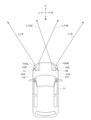
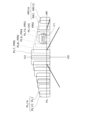
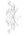
図1に示すように、左側車両用前照灯100Lは、車両Vの前部の左側に装備されていて、右側車両用前照灯100Rは、車両Vの前部の右側に装備されている。 (Description of Vehicle Headlights 100L and 100R)
As shown in FIG. 1, theleft vehicle headlamp 100L is mounted on the left front portion of the vehicle V, and the right vehicle headlamp 100R is mounted on the right front portion of the vehicle V. .
図1に示すように、左側車両用前照灯100Lは、車両Vの前部の左側に装備されていて、右側車両用前照灯100Rは、車両Vの前部の右側に装備されている。 (Description of
As shown in FIG. 1, the
車両用前照灯100L、100Rは、図1に示すように、それぞれ、ランプハウジング101と、ランプレンズ102と、ランプユニット1L、1Rと、制御装置(図示せず)と、を備える。
As shown in FIG. 1, the vehicle headlights 100L and 100R each include a lamp housing 101, a lamp lens 102, lamp units 1L and 1R, and a control device (not shown).
ランプハウジング101は、光不透過性の樹脂部材から構成されている。ランプレンズ102は、光透過性の樹脂部材から構成されている。ランプレンズ102は、アウターレンズあるいはアウターカバーである。ランプレンズ102の表面(後記の灯室103側の面に対して反対側の面)の平面視形状は、図1に示すように、車両Vの意匠面に沿って、車両内側から車両外側に行くに従って、車両Vの前側から後側に徐々に後退したスラント形状をなしている。ランプハウジング101およびランプレンズ102により、灯室103が形成されている。灯室103内には、ランプユニット1L、1Rが、配置されている。
The lamp housing 101 is made of a light-impermeable resin member. The lamp lens 102 is made of a light-transmissive resin member. The lamp lens 102 is an outer lens or outer cover. As shown in FIG. 1, the surface of the lamp lens 102 (the surface on the side opposite to the surface on the side of the lamp chamber 103 to be described later) has a planar shape along the design surface of the vehicle V from the inside to the outside of the vehicle. It has a slant shape that gradually recedes from the front side of the vehicle V to the rear side as it goes. A lamp chamber 103 is formed by the lamp housing 101 and the lamp lens 102 . In the lamp chamber 103, lamp units 1L and 1R are arranged.
(制御装置の説明)
制御装置は、図示されていないが、車両Vに装備されている。制御装置は、検出部と、検出制御部と、点灯消灯制御部と、を有する。 (Explanation of control device)
A control device is installed in the vehicle V, although not shown. The control device has a detection section, a detection control section, and a lighting/light-out control section.
制御装置は、図示されていないが、車両Vに装備されている。制御装置は、検出部と、検出制御部と、点灯消灯制御部と、を有する。 (Explanation of control device)
A control device is installed in the vehicle V, although not shown. The control device has a detection section, a detection control section, and a lighting/light-out control section.
検出部は、たとえば、車両Vのフロントウインドウガラスの上縁の中央に配置されている撮像装置(カメラ)、車両Vのフロントグリルの中央に配置されているミリ波レーダなどから構成されている。
The detection unit is composed of, for example, an imaging device (camera) placed in the center of the upper edge of the front window glass of the vehicle V, a millimeter wave radar placed in the center of the front grille of the vehicle V, and the like.
撮像装置は、自車両V(車両の符号「V」と同符号を使用)に対する対向車V1や先行車V2を含む画像を撮像する。ミリ波レーダは、自車両Vに対する対向車V1や先行車V2までの距離を測定する。検出部は、検出信号をインターフェースを介して検出制御部に出力する。
The imaging device captures an image including the oncoming vehicle V1 and the preceding vehicle V2 for the own vehicle V (using the same code as the vehicle code "V"). The millimeter wave radar measures the distance from the host vehicle V to the oncoming vehicle V1 and the preceding vehicle V2. The detector outputs a detection signal to the detection controller via the interface.
検出制御部は、検出制御用のECUであって、MPUやCPUなどの演算制御電子機器と、RAMやROMなどの記憶電子機器と、を有する。検出制御部は、演算制御電子機器が記憶電子機器に記憶されている所定のプログラムを実行することにより、検出部からの検出信号に基づいて、対向車V1や先行車V2の位置や距離を演算し、演算信号をインターフェースを介して点灯消灯制御部に出力する。
The detection control unit is an ECU for detection control, and includes arithmetic control electronic devices such as MPU and CPU, and storage electronic devices such as RAM and ROM. The detection control section calculates the position and distance of the oncoming vehicle V1 and the preceding vehicle V2 based on the detection signal from the detection section by executing a predetermined program stored in the storage electronic device by the arithmetic control electronic device. and outputs the calculated signal to the lighting/lighting/light-out control unit via the interface.
点灯消灯制御部は、点灯消灯制御用のECUであって、MPUやCPUなどの演算制御電子機器と、RAMやROMなどの記憶電子機器と、を有する。点灯消灯制御部は、演算制御電子機器が記憶電子機器に記憶されている所定のプログラムを実行することにより、検出制御部からの演算信号に基づいて、後記の複数個、この例では、10個の発光素子LED1~LED10の点灯消灯増減光を制御する。
The lighting and extinguishing control unit is an ECU for lighting and extinguishing control, and includes arithmetic control electronic devices such as MPU and CPU, and storage electronic devices such as RAM and ROM. The lighting and extinguishing control unit executes a predetermined program stored in the storage electronic device by the arithmetic control electronic device, and based on the calculation signal from the detection control unit, a plurality of, in this example, 10 lighting/extinguishing control of the light emitting elements LED1 to LED10.
(ランプユニット1L、1Rの説明)
左側車両用前照灯100Lの左側ランプユニット1Lは、図9(A)に示すように、左側ハイビーム配光パターンPLを車両Vの前方に照射する。一方、右側車両用前照灯100Rの右側ランプユニット1Rは、図9(B)に示すように、右側ハイビーム配光パターンPRを車両Vの前方に照射する。 (Description of lamp units 1L and 1R)
Theleft lamp unit 1L of the left vehicle headlamp 100L irradiates the front of the vehicle V with the left high beam light distribution pattern PL as shown in FIG. 9(A). On the other hand, the right lamp unit 1R of the right vehicle headlamp 100R irradiates the front of the vehicle V with the right high beam light distribution pattern PR, as shown in FIG. 9B.
左側車両用前照灯100Lの左側ランプユニット1Lは、図9(A)に示すように、左側ハイビーム配光パターンPLを車両Vの前方に照射する。一方、右側車両用前照灯100Rの右側ランプユニット1Rは、図9(B)に示すように、右側ハイビーム配光パターンPRを車両Vの前方に照射する。 (Description of
The
左側ハイビーム配光パターンPLと右側ハイビーム配光パターンPRとは、重畳されて、図10に示すように、全体ハイビーム配光パターンPを形成する。全体ハイビーム配光パターンPは、この例では、車両Vの前側の近辺から遠方までの広い範囲を照射し、かつ、高光度で照射するワイドハイビーム配光パターンである。
The left high-beam light distribution pattern PL and the right high-beam light distribution pattern PR are superimposed to form an overall high-beam light distribution pattern P, as shown in FIG. In this example, the overall high beam light distribution pattern P is a wide high beam light distribution pattern that irradiates a wide range from the vicinity of the front side of the vehicle V to the far side and irradiates with high luminous intensity.
ランプユニット1L、1Rは、配光可変タイプのランプユニットであって、いわゆる、ADB(Adaptive Driving Beam)タイプのランプユニットである。ランプユニット1L、1Rは、対向車V1や先行車V2などの前方車両が存在しない時には、図10に示す全体ハイビーム配光パターンPを照射する。一方、ランプユニット1L、1Rは、前方車両が存在する時には、前方車両が存在する領域(図11および図12中の破線にて示す領域)をその周囲の領域(図11および図12中の実線にて示す領域)よりも暗くなるように制御する。
The lamp units 1L and 1R are variable light distribution type lamp units, and are so-called ADB (Adaptive Driving Beam) type lamp units. The lamp units 1L and 1R emit the overall high beam light distribution pattern P shown in FIG. 10 when there is no forward vehicle such as an oncoming vehicle V1 or a preceding vehicle V2. On the other hand, when there is a vehicle ahead, the lamp units 1L and 1R cover the area where the vehicle ahead (the area indicated by the dashed lines in FIGS. 11 and 12) The area indicated by ) is controlled to be darker.
すなわち、ランプユニット1L、1Rは、後記の光源2の発光素子LED1~LED10の点灯消灯増光減光を制御装置で制御することにより、前方車両が存在する後記の部分配光パターンを消灯または減光させて、全体ハイビーム配光パターンPを変化させる。
That is, the lamp units 1L and 1R control the lighting/extinguishing brightness/decrease of the light emitting elements LED1 to LED10 of the light source 2 described later with the control device, thereby extinguishing or dimming the partial light distribution pattern described later in which the vehicle ahead is present. to change the overall high beam light distribution pattern P.
(右側ランプユニット1Rの説明)
以下、右側ランプユニット1Rについて、図2から図4を参照して説明する。ここで、右側ランプユニット1Rにおいて、車両外側は、車両Vの右側であり、車両内側は、車両Vの左側であり、以下、「車両外側」を「右側」と称し、「車両内側」を「左側」と称する。一方、左側ランプユニット1Lにおいて、車両外側は、車両Vの左側であり、車両内側は、車両Vの右側であり、以下、「車両外側」を「左側」と称し、「車両内側」を「右側」と称する。 (Description ofright lamp unit 1R)
Theright lamp unit 1R will be described below with reference to FIGS. 2 to 4. FIG. Here, in the right lamp unit 1R, the vehicle outer side is the right side of the vehicle V, and the vehicle inner side is the left side of the vehicle V. called "left side". On the other hand, in the left lamp unit 1L, the vehicle outer side is the left side of the vehicle V, and the vehicle inner side is the right side of the vehicle V. ”.
以下、右側ランプユニット1Rについて、図2から図4を参照して説明する。ここで、右側ランプユニット1Rにおいて、車両外側は、車両Vの右側であり、車両内側は、車両Vの左側であり、以下、「車両外側」を「右側」と称し、「車両内側」を「左側」と称する。一方、左側ランプユニット1Lにおいて、車両外側は、車両Vの左側であり、車両内側は、車両Vの右側であり、以下、「車両外側」を「左側」と称し、「車両内側」を「右側」と称する。 (Description of
The
左側ランプユニット1Lは、右側ランプユニット1Rとほぼ同様の構成であって、左右を反転させた構成をなすものである。このため、左側ランプユニット1Lについての説明および図2から図4と同様の図示を省略する。また、「左右両側」「左側」「右側」の文言を、適宜省略する。
The left lamp unit 1L has substantially the same configuration as the right lamp unit 1R, and has a left-right reversed configuration. Therefore, description of the left lamp unit 1L and illustrations similar to those in FIGS. 2 to 4 are omitted. In addition, the terms “left and right sides”, “left side”, and “right side” are omitted as appropriate.
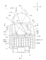
ランプユニット1Rは、光源2と、リフレクタ3と、レンズ4と、ヒートシンク5と、ファンユニット6と、を備える。光源2、リフレクタ3、レンズ4、ヒートシンク5およびファンユニット6は、フレーム部材(図示せず)に取り付けられていて、かつ、フレーム部材やブラケット部材(図示せず)を介してランプハウジング101に取り付けられている。
The lamp unit 1R includes a light source 2, a reflector 3, a lens 4, a heat sink 5, and a fan unit 6. The light source 2, reflector 3, lens 4, heat sink 5, and fan unit 6 are attached to a frame member (not shown) and attached to the lamp housing 101 via the frame member and bracket member (not shown). It is
(光源2の説明)
光源2は、図2から図4に示すように、複数個、この例では、10個の発光素子LED1、LED2、LED3、LED4、LED5、LED6、LED7、LED8、LED9、LED10(以下、「LED1~LED10」と称する)と、基板20と、を有する。ここで、10個の発光素子LED1~LED10を、左側から第1発光素子LED1~第10発光素子LED10と称する。 (Explanation of light source 2)
As shown in FIGS. 2 to 4, thelight source 2 includes a plurality of, in this example, ten light emitting elements LED1, LED2, LED3, LED4, LED5, LED6, LED7, LED8, LED9, and LED10 (hereinafter referred to as "LED1 LED 10”) and a substrate 20. Here, the ten light emitting elements LED1 to LED10 are referred to as a first light emitting element LED1 to a tenth light emitting element LED10 from the left.
光源2は、図2から図4に示すように、複数個、この例では、10個の発光素子LED1、LED2、LED3、LED4、LED5、LED6、LED7、LED8、LED9、LED10(以下、「LED1~LED10」と称する)と、基板20と、を有する。ここで、10個の発光素子LED1~LED10を、左側から第1発光素子LED1~第10発光素子LED10と称する。 (Explanation of light source 2)
As shown in FIGS. 2 to 4, the
すなわち、10個の発光素子LED1~LED10のうち、最も左側(車両内側)に位置する発光素子(請求の範囲に記載の最内側発光素子)は、第1発光素子LED1である。第1発光素子LED1の右隣に位置する発光素子(請求の範囲に記載の次内側発光素子)は、第2発光素子LED2である。10個の発光素子LED1~LED10のうち、最も右側(車両外側)に位置する発光素子(請求の範囲に記載の最外側発光素子)は、第10発光素子LED10である。第10発光素子LED10の左隣に位置する発光素子(請求の範囲に記載の次外側発光素子)は、第9発光素子LED9である。
That is, of the ten light emitting elements LED1 to LED10, the light emitting element located on the leftmost side (vehicle inner side) (the innermost light emitting element in the claims) is the first light emitting element LED1. A light-emitting element positioned to the right of the first light-emitting element LED1 (the next inner light-emitting element in the claims) is the second light-emitting element LED2. Among the ten light emitting elements LED1 to LED10, the rightmost light emitting element (vehicle outer side) (the outermost light emitting element in the claims) is the tenth light emitting element LED10. A light emitting element positioned to the left of the tenth light emitting element LED10 (second outer light emitting element in claims) is a ninth light emitting element LED9.
10個の発光素子LED1~LED10は、この例では、LEDアレイであって、基板20の一面(前面)に左右に水平方向に配列されている。10個の発光素子LED1~LED10の発光面は、矩形形状をなしている。10個の発光素子LED1~LED10の点灯消灯増光減光は、前記の制御装置により、制御されている。基板20の他面(後面)は、ヒートシンク5の取付部50に取り付けられている。
In this example, the ten light emitting elements LED1 to LED10 are an LED array, and are arranged horizontally on one surface (front surface) of the substrate 20 in the left and right direction. The light emitting surfaces of the ten light emitting elements LED1 to LED10 are rectangular. The lighting/extinguishing/increasing/decreasing of the ten light-emitting elements LED1 to LED10 is controlled by the control device. The other surface (rear surface) of the substrate 20 is attached to the attachment portion 50 of the heat sink 5 .
10個の発光素子LED1~LED10の発光面から放射(放出)される光(放射光、放出光)は、ランバーシアン状をなす。この結果、発光素子LED1~LED10から光は、車両Vの前方に上下左右に広い範囲に亘って放射される。
Light emitted (emitted) from the light emitting surfaces of the ten light emitting elements LED1 to LED10 (radiated light, emitted light) forms a Lambertian shape. As a result, light is emitted from the light emitting elements LED1 to LED10 over a wide range in front of the vehicle V in the vertical and horizontal directions.
この結果、発光素子LED1~LED10からの大部分の光は、直射光として、レンズ4の後記の入射面40に入射する。また、発光素子LED1~LED10からの下側の部分の光は、リフレクタ3の後記の反射面30で反射されて、反射光として、レンズ4の入射面40に入射する。
As a result, most of the light from the light emitting elements LED1 to LED10 enters the incident surface 40 of the lens 4 as direct light. Further, the light from the light emitting elements LED1 to LED10 in the lower part is reflected by the reflecting surface 30 of the reflector 3, which will be described later, and enters the incident surface 40 of the lens 4 as reflected light.
さらに、第1発光素子LED1および第2発光素子LED2からの左側の部分の光L1、L2は、図2に示すように、リフレクタ3の後記の内側反射面30Lに入射する。なお、第3発光素子LED3から第10発光素子LED10までの左側の部分の光(図示せず)も、リフレクタ3の後記の内側反射面30Lに入射する。
Further, the left-side lights L1 and L2 from the first light-emitting element LED1 and the second light-emitting element LED2 are incident on the inner reflecting surface 30L of the reflector 3, which will be described later, as shown in FIG. The light (not shown) of the left portion from the third light emitting element LED3 to the tenth light emitting element LED10 also enters the inner reflecting surface 30L of the reflector 3, which will be described later.
一方、第9発光素子LED9および第10発光素子LED10からの右側の部分の光L9、L10は、図2に示すように、リフレクタ3の後記の外側反射面30Rに入射する。なお、第1発光素子LED1から第8発光素子LED8までの右側の部分の光(図示せず)も、リフレクタ3の後記の外側反射面30Rに入射する。
On the other hand, the light L9 and L10 in the right part from the ninth light emitting element LED9 and the tenth light emitting element LED10 are incident on the outer reflecting surface 30R of the reflector 3, which will be described later, as shown in FIG. The light (not shown) of the right portion of the first light emitting element LED1 to the eighth light emitting element LED8 is also incident on the outer reflecting surface 30R of the reflector 3, which will be described later.
(リフレクタ3の説明)
リフレクタ3は、光源2とレンズ4との間に配置されている。リフレクタ3は、本体部31と、本体部31の左右両側に一体に設けられている取付部31L、31Rと、を有する。本体部31は、発光素子LED1~LED10よりも下側に配置されている。左側取付部31Lは、発光素子LED1~LED10の左側に配置されている。右側取付部31Rは、発光素子LED1~LED10の右側に配置されている。左右の取付部31L、31Rは、ヒートシンク5の取付部50に取り付けられている。 (Description of reflector 3)
Areflector 3 is arranged between the light source 2 and the lens 4 . The reflector 3 has a body portion 31 and attachment portions 31L and 31R integrally provided on both left and right sides of the body portion 31 . The body portion 31 is arranged below the light emitting elements LED1 to LED10. The left mounting portion 31L is arranged on the left side of the light emitting elements LED1 to LED10. The right mounting portion 31R is arranged on the right side of the light emitting elements LED1 to LED10. The left and right attachment portions 31L and 31R are attached to the attachment portion 50 of the heat sink 5. As shown in FIG.
リフレクタ3は、光源2とレンズ4との間に配置されている。リフレクタ3は、本体部31と、本体部31の左右両側に一体に設けられている取付部31L、31Rと、を有する。本体部31は、発光素子LED1~LED10よりも下側に配置されている。左側取付部31Lは、発光素子LED1~LED10の左側に配置されている。右側取付部31Rは、発光素子LED1~LED10の右側に配置されている。左右の取付部31L、31Rは、ヒートシンク5の取付部50に取り付けられている。 (Description of reflector 3)
A
本体部31の上面には、反射面30が設けられている。反射面30は、たとえば、特開2017-195116号公報に記載の反射面を使用する。反射面30は、発光素子LED1~LED10からの下側の部分の光であって、レンズ4の入射面40の有効部分に入射しない光を、レンズ4の入射面40側に反射させて、入射面40に入射させる。これにより、発光素子LED1~LED10からの光を有効に利用することができる。
A reflective surface 30 is provided on the upper surface of the body portion 31 . For the reflecting surface 30, for example, the reflecting surface described in JP-A-2017-195116 is used. The reflecting surface 30 reflects the light of the lower part from the light emitting elements LED1 to LED10, which does not enter the effective part of the incident surface 40 of the lens 4, to the incident surface 40 side of the lens 4, and enters it. Make it incident on the surface 40 . Thereby, the light from the light emitting elements LED1 to LED10 can be effectively used.
(内側反射面30Lの説明)
左側取付部31Lの上端部分には、サイドリフレクタとしての内側反射面30Lが設けられている。内側反射面30Lは、10個の発光素子LED1~LED10よりも左側に設けられている。すなわち、内側反射面30Lは、第1発光素子LED1よりも左側(車両内側)に設けられている。また、内側反射面30Lは、発光素子LED1~LED10よりも前側に設けられている。さらに、内側反射面30Lは、この例では、自由曲面、複数の曲面、一つの曲面、複数の平面や一つの平面など、任意の面から構成されている。 (Description of inner reflectingsurface 30L)
Aninner reflecting surface 30L as a side reflector is provided at the upper end portion of the left mounting portion 31L. The inner reflecting surface 30L is provided on the left side of the ten light emitting elements LED1 to LED10. That is, the inner reflecting surface 30L is provided on the left side (vehicle inner side) of the first light emitting element LED1. In addition, the inner reflecting surface 30L is provided on the front side of the light emitting elements LED1 to LED10. Furthermore, in this example, the inner reflecting surface 30L is composed of an arbitrary surface such as a free curved surface, a plurality of curved surfaces, a single curved surface, a plurality of flat surfaces, or a single flat surface.
左側取付部31Lの上端部分には、サイドリフレクタとしての内側反射面30Lが設けられている。内側反射面30Lは、10個の発光素子LED1~LED10よりも左側に設けられている。すなわち、内側反射面30Lは、第1発光素子LED1よりも左側(車両内側)に設けられている。また、内側反射面30Lは、発光素子LED1~LED10よりも前側に設けられている。さらに、内側反射面30Lは、この例では、自由曲面、複数の曲面、一つの曲面、複数の平面や一つの平面など、任意の面から構成されている。 (Description of inner reflecting
An
内側反射面30Lには、図2中の実線矢印に示すように、第1発光素子LED1からの光のうち左側の部分の光L1が入射する。内側反射面30Lは、図2中の実線矢印に示すように、入射した第1発光素子LED1からの光L1を、反射光L11として、レンズ4の入射面40に反射させる。反射光L11は、レンズ4の入射面40うち、光軸Zよりも左側であって、光軸Zよりも上側の有効部に入射する。レンズ4に入射した反射光L11は、後記の拡散配光パターンPL1C、PR1Cとして、レンズ4から車両Vの前方に照射される。
As indicated by the solid line arrow in FIG. 2, the light L1 of the left part of the light from the first light emitting element LED1 is incident on the inner reflecting surface 30L. 2, the inner reflecting surface 30L reflects the incident light L1 from the first light emitting element LED1 to the incident surface 40 of the lens 4 as reflected light L11. The reflected light L11 is incident on an effective portion on the left side of the optical axis Z and above the optical axis Z in the incident surface 40 of the lens 4 . The reflected light L11 incident on the lens 4 is irradiated forward of the vehicle V from the lens 4 as diffused light distribution patterns PL1C and PR1C, which will be described later.
また、内側反射面30Lには、図2中の破線矢印に示すように、第2発光素子LED2からの光のうち左側の部分の光L2が入射する。内側反射面30Lは、図2中の破線矢印に示すように、入射した第2発光素子LED2からの光を、反射光L21として、光軸Zよりも上側であって、入射面40の有効部以外、すなわち、レンズ4の斜め右上側の外に反射させる。このため、第2発光素子LED2からの光であって、内側反射面30Lで反射した反射光L21は、レンズ4に入射しないので、後記の第2部分配光パターンPL2、PR2の左側縦カットオフラインCL2Lおよび右側縦カットオフラインへCL2Rの影響がない。
In addition, as indicated by the dashed arrow in FIG. 2, the light L2 of the left part of the light from the second light emitting element LED2 is incident on the inner reflecting surface 30L. As indicated by the dashed arrow in FIG. 2, the inner reflecting surface 30L converts incident light from the second light emitting element LED2 into reflected light L21, which is above the optical axis Z and is an effective portion of the incident surface 40. Other than that, that is, the light is reflected outside the oblique upper right side of the lens 4 . Therefore, the reflected light L21, which is the light from the second light emitting element LED2 and is reflected by the inner reflecting surface 30L, does not enter the lens 4. Therefore, the left vertical cut-off line of the second partial light distribution patterns PL2 and PR2 described below is not incident on the lens 4. There is no effect of CL2R on CL2L and right longitudinal cut-off line.
さらに、内側反射面30Lには、第3発光素子LED3から第10発光素子LED10までの左側の部分の光も入射する。しかしながら、第3発光素子LED3から第10発光素子LED10までの光は、第2発光素子LED2からの光であって、内側反射面30Lで反射した反射光L21と同様に、レンズ4には入射しない。しかも、第3発光素子LED3から第10発光素子LED10までの光は、後記の第3部分配光パターンPL3、PR3から第10部分配光パターンPL10、PL10までの左側縦カットオフラインおよび右側縦カットオフラインへの影響がないほど弱いので、レンズ4に入射したとしても、左側縦カットオフラインおよび右側縦カットオフラインへの影響がない。
Furthermore, the light from the left portion of the third light emitting element LED3 to the tenth light emitting element LED10 also enters the inner reflecting surface 30L. However, the light from the third light emitting element LED3 to the tenth light emitting element LED10 is light from the second light emitting element LED2, and does not enter the lens 4 like the reflected light L21 reflected by the inner reflecting surface 30L. . Moreover, the light from the third light emitting element LED3 to the tenth light emitting element LED10 is cut off from the left vertical cut-off line and the right vertical cut-off line from the third partial light distribution patterns PL3, PR3 to the tenth partial light distribution patterns PL10, PL10 which will be described later. is so weak that it does not affect the left vertical cut-off line and the right vertical cut-off line even if it is incident on the lens 4 .
(外側反射面30Rの説明)
右側取付部31Rの上端部分には、サイドリフレクタとしての外側反射面30Rが設けられている。外側反射面30Rは、10個の発光素子LED1~LED10よりも右側に設けられている。すなわち、外側反射面30Rは、第10発光素子LED10よりも右側(車両外側)に設けられている。また、外側反射面30Rは、発光素子LED1~LED10よりも前側に設けられている。さらに、外側反射面30Rは、この例では、第1焦点F1が第10発光素子LED10に位置し、第2焦点F2がレンズ4の入射面40のうち光軸Zから左側に位置する楕円を上下に延ばした楕円面から構成されている。 (Description of theouter reflecting surface 30R)
Anouter reflecting surface 30R as a side reflector is provided at the upper end portion of the right mounting portion 31R. The outer reflecting surface 30R is provided on the right side of the ten light emitting elements LED1 to LED10. That is, the outer reflecting surface 30R is provided on the right side (vehicle outer side) of the tenth light emitting element LED10. Further, the outer reflecting surface 30R is provided on the front side of the light emitting elements LED1 to LED10. Furthermore, in this example, the outer reflecting surface 30R has a first focal point F1 located on the tenth light emitting element LED10 and a second focal point F2 on an ellipse located on the left side of the optical axis Z in the incident surface 40 of the lens 4. It consists of an ellipsoid extending into
右側取付部31Rの上端部分には、サイドリフレクタとしての外側反射面30Rが設けられている。外側反射面30Rは、10個の発光素子LED1~LED10よりも右側に設けられている。すなわち、外側反射面30Rは、第10発光素子LED10よりも右側(車両外側)に設けられている。また、外側反射面30Rは、発光素子LED1~LED10よりも前側に設けられている。さらに、外側反射面30Rは、この例では、第1焦点F1が第10発光素子LED10に位置し、第2焦点F2がレンズ4の入射面40のうち光軸Zから左側に位置する楕円を上下に延ばした楕円面から構成されている。 (Description of the
An
外側反射面30Rには、図2中の実線矢印に示すように、第10発光素子LED10からの光のうち右側の部分の光L10が入射する。外側反射面30Rは、図2中の実線矢印に示すように、入射した第10発光素子LED10からの光L10を、反射光L101として、レンズ4の入射面40に反射させる。反射光L101は、レンズ4の入射面40のうち、第1発光素子LED1からの光L1であって内側反射面30Lからの反射光L11よりも右側でかつ光軸Zよりも左側の有効部に主に入射する。レンズ4に入射した反射光L101は、後記の付加配光パターンPL10C、PR10Cとして、レンズ4から車両Vの前方に照射される。
As indicated by the solid arrow in FIG. 2, the light L10 on the right side of the light from the tenth light emitting element LED10 is incident on the outer reflecting surface 30R. The outer reflecting surface 30R reflects the incident light L10 from the tenth light emitting element LED10 onto the incident surface 40 of the lens 4 as reflected light L101, as indicated by the solid arrow in FIG. The reflected light L101 is the light L1 from the first light emitting element LED1 on the incident surface 40 of the lens 4, and enters an effective portion on the right side of the reflected light L11 from the inner reflecting surface 30L and on the left side of the optical axis Z. Incident mainly. The reflected light L101 incident on the lens 4 is projected forward of the vehicle V from the lens 4 as additional light distribution patterns PL10C and PR10C, which will be described later.
また、外側反射面30Rには、図2中の破線矢印に示すように、第9発光素子LED9からの光のうち右側の部分の光L9が入射する。外側反射面30Rは、図2中の破線矢印に示すように、第9発光素子LED9からの光L9を、反射光L91として、左側であって、入射面40の有効部以外、すなわち、レンズ4の左側の外に反射させる。このため、第9発光素子LED9からの光であって、外側反射面30Rで反射した反射光L91は、レンズ4に入射しないので、全体ハイビーム配光パターンPへの影響がない。
In addition, as indicated by the dashed arrow in FIG. 2, the light L9 on the right side of the light from the ninth light emitting element LED9 is incident on the outer reflecting surface 30R. As shown by the dashed arrow in FIG. 2, the outer reflecting surface 30R is the left side of the light L9 from the ninth light emitting element LED9 as the reflected light L91, and is located outside the effective portion of the incident surface 40, that is, the lens 4. Reflect out the left side of the Therefore, the reflected light L91, which is the light from the ninth light emitting element LED9 and is reflected by the outer reflecting surface 30R, does not enter the lens 4, so that the overall high beam light distribution pattern P is not affected.
なお、外側反射面30Rには、第1発光素子LED1から第8発光素子LED8までの右側の部分の光が入射する。しかしながら、第1発光素子LED1から第8発光素子LED8までの右側の部分の光は、全体ハイビーム配光パターンPへの影響がないほど弱い。このため、第1発光素子LED1から第8発光素子LED8までの光は、全体ハイビーム配光パターンPへの影響がない。
Note that light from the right portion of the first light emitting element LED1 to the eighth light emitting element LED8 is incident on the outer reflecting surface 30R. However, the light from the right portion of the first light emitting element LED1 to the eighth light emitting element LED8 is so weak that it does not affect the entire high beam light distribution pattern P. Therefore, the light from the first light emitting element LED1 to the eighth light emitting element LED8 does not affect the overall high beam light distribution pattern P. FIG.
(レンズ4の説明)
レンズ4は、図2および図3に示すように、この例では、投影レンズであって、非球面レンズから構成されている。レンズ4は、入射面40と、出射面41と、光軸Zと、を有する。なお、この例において、光軸Zは、図2に示すように、第6発光素子LED6と第7発光素子LED7との間を通っている。 (Description of lens 4)
As shown in FIGS. 2 and 3, thelens 4 is, in this example, a projection lens and is composed of an aspherical lens. The lens 4 has an entrance surface 40, an exit surface 41, and an optical axis Z. As shown in FIG. In this example, the optical axis Z passes between the sixth light emitting element LED6 and the seventh light emitting element LED7, as shown in FIG.
レンズ4は、図2および図3に示すように、この例では、投影レンズであって、非球面レンズから構成されている。レンズ4は、入射面40と、出射面41と、光軸Zと、を有する。なお、この例において、光軸Zは、図2に示すように、第6発光素子LED6と第7発光素子LED7との間を通っている。 (Description of lens 4)
As shown in FIGS. 2 and 3, the
レンズ4は、10個の発光素子LED1~LED10からの光を、10個の発光素子LED1~LED10毎に、制御して、複数個、この例では、10個の部分配光パターンPL1~PL10、PR1~PR10(図9を参照)として、車両Vの前方に照射する。ここで、10個の発光素子LED1~LED10からの光は、この例では、10個の発光素子LED1~LED10からの直射光、および、10個の発光素子LED1~LED10からの光であって、反射面30で反射された反射光である。10個の部分配光パターンPL1~PL10、PR1~PR10については、後で詳細に説明する。
The lens 4 controls the light from the ten light emitting elements LED1 to LED10 for each of the ten light emitting elements LED1 to LED10 to form a plurality of, in this example, ten partial light distribution patterns PL1 to PL10, The front of the vehicle V is irradiated with PR1 to PR10 (see FIG. 9). Here, the light from the ten light emitting elements LED1 to LED10 is, in this example, the direct light from the ten light emitting elements LED1 to LED10 and the light from the ten light emitting elements LED1 to LED10, It is reflected light reflected by the reflecting surface 30 . The ten partial light distribution patterns PL1 to PL10 and PR1 to PR10 will be described later in detail.
また、レンズ4は、第1発光素子LED1からの光L1であって内側反射面30Lからの反射光L11を、制御して、出射光L12(図2中の実線矢印を参照)として、すなわち、拡散配光パターンPL1C、PR1C(図5(C)、図9を参照)として、車両Vの前方に照射する。拡散配光パターンPL1C、PR1Cについては、10個の部分配光パターンと同様に、後で詳細に説明する。なお、第2発光素子LED2からの光L2であって内側反射面30Lからの反射光L21は、レンズ4の外を通過するので、図6(C)に示すように、配光パターンを形成しない。
In addition, the lens 4 controls the light L1 from the first light emitting element LED1 and the reflected light L11 from the inner reflecting surface 30L to output light L12 (see the solid line arrow in FIG. 2), that is, The front of the vehicle V is irradiated with diffused light distribution patterns PL1C and PR1C (see FIGS. 5C and 9). The diffuse light distribution patterns PL1C and PR1C will be described later in detail, as well as the ten partial light distribution patterns. Note that the light L2 from the second light emitting element LED2 and the reflected light L21 from the inner reflecting surface 30L passes through the outside of the lens 4, so as shown in FIG. 6C, it does not form a light distribution pattern. .
さらに、レンズ4は、第10発光素子LED10からの光L10であって外側反射面30Rからの反射光L101を、制御して、出射光L102(図2中の破線矢印を参照)として、すなわち、付加配光パターンPL10C、PR10C(図7(C)、図9を参照)として、車両Vの前方に照射する。付加配光パターンPL10C、PR10Cについては、10個の部分配光パターンおよび拡散配光パターンPL1C、PR1Cと同様に、後で詳細に説明する。なお、第9発光素子LED9からの光L9であって外側反射面30Rからの反射光L91は、レンズ4の外を通過するので、図8(C)に示すように、配光パターンを形成しない。
Furthermore, the lens 4 controls the reflected light L101 from the outer reflecting surface 30R, which is the light L10 from the tenth light emitting element LED10, to be emitted light L102 (see the dashed arrow in FIG. 2), that is, The front of the vehicle V is irradiated with additional light distribution patterns PL10C and PR10C (see FIGS. 7C and 9). The additional light distribution patterns PL10C and PR10C will be described later in detail, as are the ten partial light distribution patterns and the diffuse light distribution patterns PL1C and PR1C. The light L9 from the ninth light emitting element LED9 and reflected light L91 from the outer reflecting surface 30R passes through the outside of the lens 4, so as shown in FIG. 8(C), does not form a light distribution pattern. .
入射面40は、非球面、この例では、平面に近い非球面からなり、10個の発光素子LED1~LED10からの光を、それぞれ、入射光(図示せず)として、レンズ4中に制御して入射させる。
The incident surface 40 is an aspherical surface, in this example, an aspherical surface close to a plane, and controls the light from the ten light emitting elements LED1 to LED10 as incident light (not shown) into the lens 4. and make it incident.
出射面41は、非球面、この例では、球面に近い非球面からなり、10個の発光素子LED1~LED10からの光であって、入射面40に入射した入射光を、それぞれ、出射光(図示せず)として、外部すなわち車両Vの前方に制御して出射させる。
The exit surface 41 is an aspherical surface, in this example, an aspherical surface that is close to a spherical surface. (not shown), the light is controlled to be emitted to the outside, that is, to the front of the vehicle V.
このように、レンズ4の入射面40および出射面41は、後記の10個の部分配光パターンPL1~PL10、PR1~PR10、拡散配光パターンPR1C、および、付加配光パターンPR10Cの配光に基づいて、設計されかつ形成されている。
In this way, the entrance surface 40 and the exit surface 41 of the lens 4 are adapted to light distributions of ten partial light distribution patterns PL1 to PL10, PR1 to PR10, a diffuse light distribution pattern PR1C, and an additional light distribution pattern PR10C, which will be described later. Designed and built on the basis of
レンズ4の正面形状(出射面41の正面形状)は、縦幅(上下幅)が狭く、かつ、横幅(左右幅)が広い横長形状をなす。また、レンズ4の肉厚は、中央部分が厚く、中央部分から周縁部分に行くに従って、徐々に薄くなっている。さらに、入射面40の曲率半径は、出射面41の曲率半径よりも大きい。すなわち、ADBタイプのランプユニット1L、1Rのレンズ4は、10個の発光素子LED1~LED10からの光を、入射面40から入射してかつ出射面41から車両Vの前方に照射する必要がある。このため、入射面40の曲率半径が大きく、出射面41の曲率半径が小さい。
The front shape of the lens 4 (the front shape of the output surface 41) is a horizontally long shape with a narrow vertical width (vertical width) and a wide horizontal width (horizontal width). Also, the thickness of the lens 4 is thick at the central portion and gradually decreases from the central portion to the peripheral portion. Furthermore, the radius of curvature of the entrance surface 40 is greater than the radius of curvature of the exit surface 41 . That is, the lens 4 of the ADB type lamp units 1L and 1R needs to let the light from the ten light emitting elements LED1 to LED10 enter from the entrance surface 40 and irradiate the vehicle V forward from the exit surface 41. . Therefore, the radius of curvature of the entrance surface 40 is large, and the radius of curvature of the exit surface 41 is small.
(配光パターンの説明)
以下、左右のランプユニット1L、1Rから照射される配光パターンについて、図5~図12を参照して説明する。 (Description of light distribution pattern)
Light distribution patterns emitted from the left and right lamp units 1L and 1R will be described below with reference to FIGS. 5 to 12. FIG.
以下、左右のランプユニット1L、1Rから照射される配光パターンについて、図5~図12を参照して説明する。 (Description of light distribution pattern)
Light distribution patterns emitted from the left and
左側車両用前照灯100Lの左側ランプユニット1Lは、図9(A)に示すように、前記の10個の部分配光パターンPL1~PL10(PL1、PL2、PL3、PL4、PL5、PL6、PL7、PL8、PL9、PL10)、拡散配光パターンPL1Cおよび付加配光パターンPL10Cを、左側ハイビーム配光パターンPLとして、車両Vの前方に照射する。ここで、10個の部分配光パターンPL1~PL10を、左側から第1部分配光パターンPL1~第10部分配光パターンPL10と称する。
As shown in FIG. 9A, the left lamp unit 1L of the left vehicle headlamp 100L includes the ten partial light distribution patterns PL1 to PL10 (PL1, PL2, PL3, PL4, PL5, PL6, PL7 , PL8, PL9, PL10), the diffused light distribution pattern PL1C, and the additional light distribution pattern PL10C as the left high-beam light distribution pattern PL. Here, the ten partial light distribution patterns PL1 to PL10 are referred to as a first partial light distribution pattern PL1 to a tenth partial light distribution pattern PL10 from the left.
一方、右側車両用前照灯100Rの右側ランプユニット1Rは、図5~図8、図9(B)に示すように、前記の10個の部分配光パターンPR1~PR10(PR1、PR2、PR3、PR4、PR5、PR6、PR7、PR8、PR9、PR10)、拡散配光パターンPR1Cおよび付加配光パターンPR10Cを、右側ハイビーム配光パターンPRとして、車両Vの前方に照射する。ここで、10個の部分配光パターンPR1~PR10を、右側から第1部分配光パターンPR1~第10部分配光パターンPR10と称する。
On the other hand, the right lamp unit 1R of the right vehicle headlamp 100R has the ten partial light distribution patterns PR1 to PR10 (PR1, PR2, PR3) as shown in FIGS. , PR4, PR5, PR6, PR7, PR8, PR9, and PR10), the diffused light distribution pattern PR1C and the additional light distribution pattern PR10C as the right high beam light distribution pattern PR. Here, the ten partial light distribution patterns PR1 to PR10 are called a first partial light distribution pattern PR1 to a tenth partial light distribution pattern PR10 from the right side.
左右のランプユニット1L、1Rから照射される左側ハイビーム配光パターンPLと右側ハイビーム配光パターンPRとを、重畳することにより、図10から図12に示すように、前記の全体ハイビーム配光パターンPが形成される。全体ハイビーム配光パターンPにおいて、左側ハイビーム配光パターンPLの左側部分は、右側ハイビーム配光パターンPRの左側部分よりも左側に拡散されていて、右側ハイビーム配光パターンPRの右側部分は、左側ハイビーム配光パターンPLの右側部分よりも右側に拡散されている。
By superimposing the left high beam light distribution pattern PL and the right high beam light distribution pattern PR emitted from the left and right lamp units 1L and 1R, the overall high beam light distribution pattern P is formed as shown in FIGS. is formed. In the overall high beam distribution pattern P, the left portion of the left high beam distribution pattern PL is more diffused to the left than the left portion of the right high beam distribution pattern PR. The light is diffused to the right of the right portion of the light distribution pattern PL.
なお、10個の部分配光パターンPL1~PL10、PR1~PR10の形状、拡散配光パターンPL1C、PR1Cの形状および付加配光パターンPL10C、PR10Cの形状は、図5から図12に示す形状に限定されない。
The shapes of the ten partial light distribution patterns PL1 to PL10 and PR1 to PR10, the diffuse light distribution patterns PL1C and PR1C, and the additional light distribution patterns PL10C and PR10C are limited to the shapes shown in FIGS. not.
(10個の部分配光パターンPL1~PL10、PR1~PR10の説明)
10個の部分配光パターンPL1~PL10、PR1~PR10は、前記の通り、10個の発光素子LED1~LED10からの光(10個の発光素子LED1~LED10からの直射光、および、10個の発光素子LED1~LED10からの光)を、レンズ4により制御されて形成されている。 (Description of 10 partial light distribution patterns PL1 to PL10, PR1 to PR10)
The 10 partial light distribution patterns PL1 to PL10 and PR1 to PR10 are, as described above, light from the 10 light emitting elements LED1 to LED10 (direct light from the 10 light emitting elements LED1 to LED10 and direct light from the 10 light emitting elements LED1 to The light from the light emitting elements (LED1 to LED10) is controlled by thelens 4 and formed.
10個の部分配光パターンPL1~PL10、PR1~PR10は、前記の通り、10個の発光素子LED1~LED10からの光(10個の発光素子LED1~LED10からの直射光、および、10個の発光素子LED1~LED10からの光)を、レンズ4により制御されて形成されている。 (Description of 10 partial light distribution patterns PL1 to PL10, PR1 to PR10)
The 10 partial light distribution patterns PL1 to PL10 and PR1 to PR10 are, as described above, light from the 10 light emitting elements LED1 to LED10 (direct light from the 10 light emitting elements LED1 to LED10 and direct light from the 10 light emitting elements LED1 to The light from the light emitting elements (LED1 to LED10) is controlled by the
すなわち、10個の部分配光パターンPL1~PL10、PR1~PR10は、レンズ4から照射された10個の発光素子LED1~LED10の発光面の投影像から形成されていて、かつ、10個の発光素子LED1~LED10に、それぞれ、1対1で対応している。10個の部分配光パターンPL1~PL10、PR1~PR10は、左右に水平方向に配列されている。
That is, the ten partial light distribution patterns PL1 to PL10 and PR1 to PR10 are formed from projection images of the light emitting surfaces of the ten light emitting elements LED1 to LED10 irradiated from the lens 4, and the ten light emitting elements There is a one-to-one correspondence with the elements LED1 to LED10. The ten partial light distribution patterns PL1 to PL10 and PR1 to PR10 are horizontally arranged on the left and right.
10個の部分配光パターンPL1~PL10、PR1~PR10の点灯消灯増減光は、それぞれ、制御装置により制御されている10個の発光素子LED1~LED10の点灯消灯増減光に基づいて、制御されている。これにより、10個の部分配光パターンPL1~PL10、PR1~PR10は、全体ハイビーム配光パターンPにおいて、高い分解能を有する。
The lighting/unlit dimming of the 10 partial light distribution patterns PL1 to PL10 and PR1 to PR10 is controlled based on the lit/unlit dimming of the 10 light emitting elements LED1 to LED10 controlled by the control device. there is Accordingly, the ten partial light distribution patterns PL1 to PL10 and PR1 to PR10 have high resolution in the overall high beam light distribution pattern P. FIG.
(縦カットオフラインの説明)
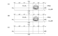
10個の部分配光パターンPL1~PL10、PR1~PR10の左右両端には、それぞれ、左側縦カットオフライン、右側縦カットオフラインが形成されている。たとえば、図5(B)、図9(B)に示すように、右側の第1部分配光パターンPR1の左右両端には、左側縦カットオフラインCL1L、右側縦カットオフラインCL1Rが形成されている。また、図6(A)、(B)、図9(B)に示すように、右側の第2部分配光パターンPR2の左右両端には、左側縦カットオフラインCL2L、右側縦カットオフラインCL2Rが形成されている。さらに、図7(B)、図9(B)に示すように、右側の第10部分配光パターンPR10の左右両端には、左側縦カットオフラインCL10L、右側縦カットオフラインCL10Rが形成されている。さらにまた、図8(A)、(B)、図9(B)に示すように、右側の第9部分配光パターンPR9の左右両端には、左側縦カットオフラインCL9L、右側縦カットオフラインCL9Rが形成されている。 (Description of vertical cut-off line)
A left vertical cut-off line and a right vertical cut-off line are formed at the left and right ends of the ten partial light distribution patterns PL1 to PL10 and PR1 to PR10, respectively. For example, as shown in FIGS. 5B and 9B, a left vertical cut-off line CL1L and a right vertical cut-off line CL1R are formed at both left and right ends of the right first partial light distribution pattern PR1. Further, as shown in FIGS. 6A, 6B, and 9B, a left vertical cutoff line CL2L and a right vertical cutoff line CL2R are formed at the left and right ends of the right second partial light distribution pattern PR2. It is Further, as shown in FIGS. 7B and 9B, a left vertical cutoff line CL10L and a right vertical cutoff line CL10R are formed at both left and right ends of the tenth partial light distribution pattern PR10 on the right side. Furthermore, as shown in FIGS. 8A, 8B, and 9B, a left vertical cutoff line CL9L and a right vertical cutoff line CL9R are provided at the left and right ends of the right ninth partial light distribution pattern PR9. formed.
この左側縦カットオフラインおよび右側縦カットオフラインは、前方車両が存在する領域(図11中の破線にて示す部分配光パターンPL8~PL10、PR2~PR5、PL10C、および、図12中の破線にて示す部分配光パターンPL5~PL8、PR5~PR8)をその周囲の領域(図11および図12中の実線にて示す部分配光パターン)よりも暗くした時に、隣に位置する明るい領域(図11中の実線にて示す部分配光パターンPL7、PR6 PR1、および、図12中の実線にて示す部分配光パターンPL4、PR8 PL9、PR4)が前方車両にグレアを与えないようにするためのものである。これにより、10個の部分配光パターンPL1~PL10、PR1~PR10の左側縦カットオフラインおよび右側縦カットオフラインは、レンズ4で、高精度に形成され、かつ、高精度に制御されている。
The left vertical cut-off line and the right vertical cut-off line are areas where the vehicle ahead exists (partial light distribution patterns PL8 to PL10, PR2 to PR5, and PL10C indicated by broken lines in FIG. 11, and the broken lines in FIG. When the partial light distribution patterns PL5 to PL8 and PR5 to PR8 shown in FIG. 11) are made darker than the surrounding areas (partial light distribution patterns indicated by solid lines in FIGS. 11 and 12), the adjacent bright areas (FIG. 11 Partial light distribution patterns PL7, PR6 (PR1) indicated by solid lines in the middle, and partial light distribution patterns PL4, PR8 (PL9, PR4) indicated by solid lines in FIG. is. As a result, the left vertical cut-off lines and the right vertical cut-off lines of the ten partial light distribution patterns PL1 to PL10 and PR1 to PR10 are formed and controlled with high precision by the lens 4 .
(拡散配光パターンPL1C、PR1Cの説明)
拡散配光パターンPL1C、PR1Cは、図5、図9~図12に示すように、第1発光素子LED1からの光L1であって、内側反射面30Lで反射された反射光L11を、レンズ4により制御されて形成されている。拡散配光パターンPL1C、PR1Cは、10個の部分配光パターンPL1~PL10、PR1~PR10の車両外側の第1部分配光パターンPL1、PR1に重畳されている。 (Description of diffuse light distribution patterns PL1C and PR1C)
As shown in FIGS. 5 and 9 to 12, the diffused light distribution patterns PL1C and PR1C are the light L1 from the first light emitting element LED1 and the reflected light L11 reflected by the inner reflecting surface 30L. is formed under the control of The diffused light distribution patterns PL1C, PR1C are superimposed on the first partial light distribution patterns PL1, PR1 outside the vehicle of the ten partial light distribution patterns PL1 to PL10, PR1 to PR10.
拡散配光パターンPL1C、PR1Cの車両外側の縁、この例では、車両外側縦カットオフラインCL1RC(図5(C)、図9(B)参照)は、第1部分配光パターンPL1、PR1の車両外側の縁、この例では、車両外側縦カットオフラインCL1R(図5(B)、図9(B)参照)よりも車両外側(右側)に位置している。
The edges of the diffused light distribution patterns PL1C and PR1C on the vehicle outer side, in this example, the vehicle outer longitudinal cutoff line CL1RC (see FIGS. 5(C) and 9(B)) are the vehicle-side edges of the first partial light distribution patterns PL1 and PR1. The outer edge, in this example, is located on the vehicle outer side (right side) of the vehicle outer longitudinal cutoff line CL1R (see FIGS. 5B and 9B).
これにより、拡散配光パターンPL1C、PR1Cが重畳されている第1部分配光パターンPL1A、PR1A(以下、「重畳後の第1部分配光パターンPL1A、PR1A」と称する)の車両外側の縁、この例では、車両外側縦カットオフラインCL1RC(図5(A)、図9(B)参照)は、拡散配光パターンPL1C、PR1Cが重畳されていない第1部分配光パターンPL1、PR1(以下、「重畳前の第1部分配光パターンPL1、PR1」と称する)の車両外側の縁、この例では、車両外側縦カットオフラインCL1R(図5(B)、図9(B)参照)よりも車両外側(右側)に位置している。
As a result, the vehicle outer edge of the first partial light distribution patterns PL1A and PR1A on which the diffuse light distribution patterns PL1C and PR1C are superimposed (hereinafter referred to as "first partial light distribution patterns PL1A and PR1A after superimposition"), In this example, the vehicle-outside vertical cutoff line CL1RC (see FIGS. 5A and 9B) is the first partial light distribution patterns PL1 and PR1 (hereinafter referred to as the first partial light distribution patterns PL1 and PR1 on which the diffuse light distribution patterns PL1C and PR1C are not superimposed). (referred to as "first partial light distribution patterns PL1 and PR1 before superimposition"), in this example, the vehicle outside vertical cutoff line CL1R (see FIGS. 5(B) and 9(B)). Located outside (on the right).
このため、重畳後の第1部分配光パターンPL1A、PR1Aの車両外側の部分(図5(A)、図9(B)参照)は、重畳前の第1部分配光パターンPL1、PR1の車両外側の部分(図5(B)、図9(B)参照)よりも車両外側に拡散されている。
Therefore, the portion outside the vehicle of the first partial light distribution patterns PL1A and PR1A after superimposition (see FIGS. 5A and 9B) is the same as that of the vehicle of the first partial light distribution patterns PL1 and PR1 before superimposition. It is diffused to the outside of the vehicle from the outer portion (see FIGS. 5(B) and 9(B)).
拡散配光パターンPL1C、PR1Cの領域は、第1部分配光パターンPL1A、PR1Aの領域よりも狭い。これにより、拡散配光パターンPL1C、PR1Cの車両内側の縁(図5(C)、図9(B)参照)は、第1部分配光パターンPL1、PR1の車両内側の縁、この例では、車両内側縦カットオフラインCL1L(図5(B)、図9(B)参照)よりも車両外側(右側)に位置している。
The areas of the diffused light distribution patterns PL1C and PR1C are narrower than the areas of the first partial light distribution patterns PL1A and PR1A. As a result, the edges of the diffused light distribution patterns PL1C and PR1C on the inside of the vehicle (see FIGS. 5C and 9B) are the edges of the first partial light distribution patterns PL1 and PR1 on the inside of the vehicle. It is positioned on the vehicle outer side (right side) of the vehicle inner vertical cutoff line CL1L (see FIGS. 5B and 9B).
このため、重畳後の第1部分配光パターンPL1A、PR1Aの車両内側縦カットオフラインCL1L(図5(A)、図9(B)参照)と、重畳前の第1部分配光パターンPL1、PR1の車両内側縦カットオフラインCL1L(図5(B)、図9(B)参照)とは、同一もしくはほぼ同一である。
Therefore, the vertical cut-off line CL1L (see FIGS. 5A and 9B) of the first partial light distribution patterns PL1A and PR1A after superimposition and the first partial light distribution patterns PL1 and PR1 before superimposition is the same or substantially the same as the vehicle inner longitudinal cut-off line CL1L (see FIGS. 5(B) and 9(B)).
(付加配光パターンPL10C、PR10Cの説明)
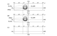
付加配光パターンPL10C、PR10Cは、図7、図9~図12に示すように、第10発光素子LED10からの光L10であって、外側反射面30Rで反射された反射光L101を、レンズ4により制御されて形成されている。 (Description of additional light distribution patterns PL10C and PR10C)
The additional light distribution patterns PL10C and PR10C, as shown in FIGS. is formed under the control of
付加配光パターンPL10C、PR10Cは、図7、図9~図12に示すように、第10発光素子LED10からの光L10であって、外側反射面30Rで反射された反射光L101を、レンズ4により制御されて形成されている。 (Description of additional light distribution patterns PL10C and PR10C)
The additional light distribution patterns PL10C and PR10C, as shown in FIGS. is formed under the control of
付加配光パターンPL10C、PR10Cは、第10部分配光パターンPL10、PR10の車両内側に重畳されている。すなわち、左側の付加配光パターンPL10Cは、図9(A)に示すように、左側の第10部分配光パターンPL10の車両内側である右側に重畳されていて、右側の付加配光パターンPR10Cは、図9(B)に示すように、右側の第10部分配光パターンPR10の車両内側である左側に重畳されている。
The additional light distribution patterns PL10C and PR10C are superimposed on the vehicle inner side of the tenth partial light distribution patterns PL10 and PR10. That is, as shown in FIG. 9A, the left additional light distribution pattern PL10C is superimposed on the right side of the left tenth partial light distribution pattern PL10, which is inside the vehicle. , are superimposed on the left side of the right tenth partial light distribution pattern PR10, which is inside the vehicle, as shown in FIG. 9B.
このため、付加配光パターンPL10C、PR10Cが重畳されている第10部分配光パターンPL10A、PR10A(以下、「重畳後の第10部分配光パターンPL10A、PR10A」と称する。図7(A)参照)の光度は、付加配光パターンPL10C、PR10Cが重畳されていない第10部分配光パターンPL10、PR10(以下、「重畳前の第10部分配光パターンPL10、PR10」と称する。図7(B)参照)の光度よりも高い。
Therefore, the tenth partial light distribution patterns PL10A and PR10A on which the additional light distribution patterns PL10C and PR10C are superimposed (hereinafter referred to as "tenth partial light distribution patterns PL10A and PR10A after superimposition". See FIG. 7A). ) is the luminous intensity of the tenth partial light distribution patterns PL10 and PR10 on which the additional light distribution patterns PL10C and PR10C are not superimposed (hereinafter referred to as “tenth partial light distribution patterns PL10 and PR10 before superimposition”. FIG. 7B ) higher than the luminosity of ).
また、付加配光パターンPL10C、PR10Cの車両内側縦カットオフラインCL10LC(図7(C)、図9(B)参照)は、第10部分配光パターンPL10、PR10の車両内側縦カットオフラインCL10L(図7(B)、図9(B)参照)よりも車両内側に若干位置している。これにより、付加配光パターンPL10C、PR10Cの車両内側の部分は、第10部分配光パターンPL10、PR10の車両内側の部分よりも車両内側に若干位置している。このため、重畳後の第10部分配光パターンPL10A、PR10Aの車両内側の部分(図7(A)、図9(B)参照)は、重畳前の第10部分配光パターンPL10、PR10の車両内側の部分(図7(B)、図9(B)参照)よりも車両内側に若干拡散されている。
The vehicle-inside vertical cutoff line CL10LC (see FIGS. 7C and 9B) of the additional light distribution patterns PL10C and PR10C is the vehicle-inside vertical cutoff line CL10L of the tenth partial light distribution patterns PL10 and PR10 (see FIG. 7(B), see FIG. 9(B)). As a result, the vehicle-inside portions of the additional light distribution patterns PL10C and PR10C are located slightly further inside the vehicle than the vehicle-inside portions of the tenth partial light distribution patterns PL10 and PR10. Therefore, the portion inside the vehicle of the tenth partial light distribution patterns PL10A and PR10A after superimposition (see FIGS. 7A and 9B) corresponds to the vehicle inside of the tenth partial light distribution patterns PL10 and PR10 before superimposition. It is slightly diffused toward the inner side of the vehicle than the inner portion (see FIGS. 7(B) and 9(B)).
なお、重畳後の第10部分配光パターンPL10A、PR10Aの車両内側の部分の拡散幅は、重畳後の第1部分配光パターンPL1A、PR1Aの車両外側の部分の拡散幅よりも狭い。また、重畳後の第10部分配光パターンPL10A、PR10Aの車両外側縦カットオフラインCL10Rと、重畳前の第10部分配光パターンPL10、PR10の車両外側縦カットオフラインCL10Rとは、同一もしくはほぼ同一である。
It should be noted that the diffusion width of the portion inside the vehicle of the tenth partial light distribution patterns PL10A and PR10A after being superimposed is narrower than the diffusion width of the portion outside the vehicle of the first partial light distribution patterns PL1A and PR1A after being superimposed. Further, the vehicle-outside vertical cutoff line CL10R of the tenth partial light distribution patterns PL10A, PR10A after superimposition and the vehicle-outside vertical cutoff line CL10R of the tenth partial light distribution patterns PL10, PR10 before superimposition are the same or substantially the same. be.
(ヒートシンク5の説明)
ヒートシンク5は、熱伝導性が高い部材、この例では、アルミダイカスト製の部材から構成されている。ヒートシンク5は、図2から図4に示すように、板形状の取付部50とフィン形状の放熱部51との一体の構造物から構成されている。 (Description of heat sink 5)
Theheat sink 5 is made of a member having high thermal conductivity, in this example, a member made of aluminum die casting. As shown in FIGS. 2 to 4, the heat sink 5 is constructed by an integral structure including a plate-shaped mounting portion 50 and a fin-shaped heat radiation portion 51. As shown in FIG.
ヒートシンク5は、熱伝導性が高い部材、この例では、アルミダイカスト製の部材から構成されている。ヒートシンク5は、図2から図4に示すように、板形状の取付部50とフィン形状の放熱部51との一体の構造物から構成されている。 (Description of heat sink 5)
The
取付部50の前面の取付面には、発光素子LED1~LED10が基板20を介して取り付けられていて、また、リフレクタ3の取付部31L、31Rが取り付けられている。取付部50の後面には、放熱部51の前面が一体に設けられている。放熱部51の複数枚のフィンは、上下方向に、平行もしくはほぼ平行である。
The light-emitting elements LED1 to LED10 are attached to the front attachment surface of the attachment portion 50 via the substrate 20, and the attachment portions 31L and 31R of the reflector 3 are attached. The rear surface of the mounting portion 50 is integrally provided with the front surface of the heat radiating portion 51 . The plurality of fins of the heat radiating portion 51 are parallel or substantially parallel in the vertical direction.
(ファンユニット6の説明)
ファンユニット6は、図2から図4に示すように、ヒートシンク5の放熱部51の後面に取り付けられている。ファンユニット6は、風をヒートシンク5に強制的にかつ直接当てることにより、ヒートシンク5を、発光素子LED1~LED10において発生した熱から、冷却させる。 (Explanation of fan unit 6)
Thefan unit 6 is attached to the rear surface of the heat radiating portion 51 of the heat sink 5, as shown in FIGS. The fan unit 6 forces and directs air against the heat sink 5 to cool the heat sink 5 from the heat generated in the light emitting elements LED1-LED10.
ファンユニット6は、図2から図4に示すように、ヒートシンク5の放熱部51の後面に取り付けられている。ファンユニット6は、風をヒートシンク5に強制的にかつ直接当てることにより、ヒートシンク5を、発光素子LED1~LED10において発生した熱から、冷却させる。 (Explanation of fan unit 6)
The
(実施形態の作用の説明)
この実施形態にかかるランプユニット1L、1R、この実施形態にかかる車両用前照灯100L、100Rは、以上のごとき構成からなり、以下、その作用について説明する。 (Description of the action of the embodiment)
The lamp units 1L and 1R according to this embodiment and the vehicle headlamps 100L and 100R according to this embodiment are constructed as described above, and their functions will be described below.
この実施形態にかかるランプユニット1L、1R、この実施形態にかかる車両用前照灯100L、100Rは、以上のごとき構成からなり、以下、その作用について説明する。 (Description of the action of the embodiment)
The
(対向車V1や先行車V2などの前方車両がいない場合の説明)
図10に示すように、対向車V1や先行車V2などの前方車両がいない場合は、制御装置の検出部が、対向車V1や先行車V2などの前方車両を検出していない。このため、左右両側のランプユニット1L、1Rの10個の発光素子LED1~LED10が、全個点灯される。 (Description when there is no forward vehicle such as an oncoming vehicle V1 or a preceding vehicle V2)
As shown in FIG. 10, when there is no forward vehicle such as the oncoming vehicle V1 or the preceding vehicle V2, the detection unit of the control device does not detect the forward vehicle such as the oncoming vehicle V1 or the preceding vehicle V2. Therefore, all the ten light emitting elements LED1 to LED10 of the lamp units 1L and 1R on the left and right sides are lit.
図10に示すように、対向車V1や先行車V2などの前方車両がいない場合は、制御装置の検出部が、対向車V1や先行車V2などの前方車両を検出していない。このため、左右両側のランプユニット1L、1Rの10個の発光素子LED1~LED10が、全個点灯される。 (Description when there is no forward vehicle such as an oncoming vehicle V1 or a preceding vehicle V2)
As shown in FIG. 10, when there is no forward vehicle such as the oncoming vehicle V1 or the preceding vehicle V2, the detection unit of the control device does not detect the forward vehicle such as the oncoming vehicle V1 or the preceding vehicle V2. Therefore, all the ten light emitting elements LED1 to LED10 of the
すると、左右両側のランプユニット1L、1Rの10個の発光素子LED1~LED10からの光は、それぞれ、直射光として、また、反射面30からの反射光として、レンズ4の入射面40に入射する。レンズ4に入射した10個の発光素子LED1~LED10からの光は、それぞれ、レンズ4の出射面41から出射して、図9~図12に示すように、左右両側の10個の部分配光パターンPL1~PL10、PR1~PR10として、車両Vの前方に照射される。
Then, the light from the ten light emitting elements LED1 to LED10 of the lamp units 1L and 1R on both the left and right sides respectively enters the incident surface 40 of the lens 4 as direct light and as reflected light from the reflecting surface 30. . The light from the ten light emitting elements LED1 to LED10 incident on the lens 4 is emitted from the emission surface 41 of the lens 4, and as shown in FIGS. The front of the vehicle V is irradiated with the patterns PL1 to PL10 and PR1 to PR10.
また、第1発光素子LED1からの光L1の一部が、外側反射面30Rで反射され、その反射光L11が、レンズ4を透過して出射され、その出射光L12が、図5、図9~図12に示すように、左右両側の拡散配光パターンPL1C、PR1Cとして、車両Vの前方に照射される。
Part of the light L1 from the first light emitting element LED1 is reflected by the outer reflecting surface 30R, the reflected light L11 is transmitted through the lens 4 and emitted, and the emitted light L12 is shown in FIGS. 12, the front of the vehicle V is irradiated with diffused light distribution patterns PL1C and PR1C on both left and right sides.
さらに、第10発光素子LED10からの光L10の一部が、内側反射面30Lで反射され、その反射光L101が、レンズ4を透過して出射され、その出射光L102が、図7、図9~図12に示すように、左右両側の付加配光パターンPL10C、PR10Cとして、車両Vの前方に照射される。
Further, part of the light L10 from the tenth light emitting element LED10 is reflected by the inner reflecting surface 30L, and the reflected light L101 is emitted through the lens 4, and the emitted light L102 is shown in FIGS. As shown in FIGS. 12 to 12, the light is emitted in front of the vehicle V as additional light distribution patterns PL10C and PR10C on both left and right sides.
左右両側の10個の部分配光パターンPL1~PL10、PR1~PR10と、左右両側の拡散配光パターンPL1C、PR1Cと、左右両側の付加配光パターンPL10C、PR10Cとは、それぞれ、重畳されて、図9~図12に示す左右両側のハイビーム配光パターンPL、PRを形成する。そして、この左右両側のハイビーム配光パターンPL、PRは、それぞれ、重畳されて、図10~図12に示す全体ハイビーム配光パターンPを形成する。
Ten partial light distribution patterns PL1 to PL10, PR1 to PR10 on both left and right sides, diffuse light distribution patterns PL1C, PR1C on both left and right sides, and additional light distribution patterns PL10C, PR10C on both left and right sides are superimposed, The left and right high beam light distribution patterns PL and PR shown in FIGS. 9 to 12 are formed. The left and right high-beam distribution patterns PL and PR are superimposed to form the overall high-beam distribution pattern P shown in FIGS. 10-12.
(対向車V1がいる場合の説明)
図11に示すように、対向車V1がいる場合は、制御装置の検出部が、対向車V1を検出する。このため、左右両側のランプユニット1L、1Rの10個の発光素子LED1~LED10のうち、対向車V1がいる領域を照射している発光素子、この例では、左側ランプユニット1Lの発光素子LED8~LED10、および、右側ランプユニット1Rの発光素子LED2~LED5は、制御装置の制御により、消灯もしくは減光される。 (Description when there is an oncoming vehicle V1)
As shown in FIG. 11, when there is an oncoming vehicle V1, the detection unit of the control device detects the oncoming vehicle V1. Therefore, among the ten light emitting elements LED1 to LED10 of the left and right lamp units 1L and 1R, the light emitting elements illuminating the area where the oncoming vehicle V1 is located, in this example, the light emitting elements LED8 to LED8 of the left lamp unit 1L. The LED 10 and the light emitting elements LED2 to LED5 of the right lamp unit 1R are extinguished or dimmed under the control of the control device.
図11に示すように、対向車V1がいる場合は、制御装置の検出部が、対向車V1を検出する。このため、左右両側のランプユニット1L、1Rの10個の発光素子LED1~LED10のうち、対向車V1がいる領域を照射している発光素子、この例では、左側ランプユニット1Lの発光素子LED8~LED10、および、右側ランプユニット1Rの発光素子LED2~LED5は、制御装置の制御により、消灯もしくは減光される。 (Description when there is an oncoming vehicle V1)
As shown in FIG. 11, when there is an oncoming vehicle V1, the detection unit of the control device detects the oncoming vehicle V1. Therefore, among the ten light emitting elements LED1 to LED10 of the left and
すると、左右両側の10個の部分配光パターンPL1~PL10、PR1~PR10と、左右両側の拡散配光パターンPL1C、PR1Cと、左右両側の付加配光パターンPL10C、PR10Cのうち、消灯された左側ランプユニット1Lの発光素子LED8~LED10、および、右側ランプユニット1Rの発光素子LED2~LED5に、それぞれ、対応する左側の部分配光パターンPL8~PL10、PL10C、および、右側の部分配光パターンPR2~PR5は、図11中の破線にて示すように、消えもしくは光度が下がる。この結果、図11に示す全体ハイビーム配光パターンPにおいて、対向車V1が存在する領域がその周囲の領域よりも暗くなり、対向車V1に対して、幻惑光を与えることが無い。
Then, among the 10 partial light distribution patterns PL1 to PL10 and PR1 to PR10 on both left and right sides, the diffused light distribution patterns PL1C and PR1C on both left and right sides, and the additional light distribution patterns PL10C and PR10C on both left and right sides, the extinguished left side The left partial light distribution patterns PL8 to PL10 and PL10C and the right partial light distribution patterns PR2 to corresponding to the light emitting elements LED8 to LED10 of the lamp unit 1L and the light emitting elements LED2 to LED5 of the right lamp unit 1R, respectively. PR5 disappears or decreases in luminosity as indicated by the dashed line in FIG. As a result, in the overall high beam light distribution pattern P shown in FIG. 11, the area where the oncoming vehicle V1 exists becomes darker than the surrounding area, and the oncoming vehicle V1 is not dazzled.
(先行車V2がいる場合の説明)
図12に示すように、先行車V2がいる場合は、制御装置の検出部が、先行車V2を検出する。このため、左右両側のランプユニット1L、1Rの10個の発光素子LED1~LED10のうち、先行車V2がいる領域を照射している発光素子、この例では、左側ランプユニット1Lの発光素子LED5~LED8および、右側ランプユニット1Rの発光素子LED5~LED8は、制御装置の制御により、消灯もしくは減光される。 (Explanation when there is a preceding vehicle V2)
As shown in FIG. 12, when there is a preceding vehicle V2, the detection unit of the control device detects the preceding vehicle V2. Therefore, among the ten light emitting elements LED1 to LED10 of the left and right lamp units 1L and 1R, the light emitting elements illuminating the area where the preceding vehicle V2 is present, in this example, the light emitting elements LED5 to LED5 of the left lamp unit 1L. The LED8 and the light-emitting elements LED5 to LED8 of the right lamp unit 1R are extinguished or dimmed under the control of the control device.
図12に示すように、先行車V2がいる場合は、制御装置の検出部が、先行車V2を検出する。このため、左右両側のランプユニット1L、1Rの10個の発光素子LED1~LED10のうち、先行車V2がいる領域を照射している発光素子、この例では、左側ランプユニット1Lの発光素子LED5~LED8および、右側ランプユニット1Rの発光素子LED5~LED8は、制御装置の制御により、消灯もしくは減光される。 (Explanation when there is a preceding vehicle V2)
As shown in FIG. 12, when there is a preceding vehicle V2, the detection unit of the control device detects the preceding vehicle V2. Therefore, among the ten light emitting elements LED1 to LED10 of the left and
すると、左右両側の10個の部分配光パターンPL1~PL10、PR1~PR10と、左右両側の拡散配光パターンPL1C、PR1Cと、左右両側の付加配光パターンPL10C、PR10Cのうち、消灯された左側ランプユニット1Lの発光素子LED5~LED8、および、右側ランプユニット1Rの発光素子LED5~LED8に、それぞれ、対応する左側の部分配光パターンPL5~PL8および、右側の部分配光パターンPR5~PR8は、図12中の破線にて示すように、消えもしくは光度が下がる。この結果、図12に示す全体ハイビーム配光パターンPにおいて、先行車V2が存在する領域がその周囲の領域よりも暗くなり、先行車V2に対して、幻惑光を与えることが無い。
Then, among the 10 partial light distribution patterns PL1 to PL10 and PR1 to PR10 on both left and right sides, the diffused light distribution patterns PL1C and PR1C on both left and right sides, and the additional light distribution patterns PL10C and PR10C on both left and right sides, the extinguished left side The left partial light distribution patterns PL5 to PL8 and the right partial light distribution patterns PR5 to PR8 corresponding to the light emitting elements LED5 to LED8 of the lamp unit 1L and the light emitting elements LED5 to LED8 of the right lamp unit 1R, respectively, As shown by the dashed line in FIG. 12, it disappears or the luminosity decreases. As a result, in the overall high beam light distribution pattern P shown in FIG. 12, the area where the preceding vehicle V2 exists becomes darker than the surrounding areas, and the preceding vehicle V2 is not dazzled.
(冷却の説明)
発光素子LED1~LED10において発生した熱は、基板20および取付部材であるヒートシンク5を介して、外部に放出される。また、ヒートシンク5は、ファンユニット6による強制空冷により、冷却される。 (Explanation of cooling)
The heat generated in the light emitting elements LED1 to LED10 is released to the outside through thesubstrate 20 and the heat sink 5 as the mounting member. Also, the heat sink 5 is cooled by forced air cooling by the fan unit 6 .
発光素子LED1~LED10において発生した熱は、基板20および取付部材であるヒートシンク5を介して、外部に放出される。また、ヒートシンク5は、ファンユニット6による強制空冷により、冷却される。 (Explanation of cooling)
The heat generated in the light emitting elements LED1 to LED10 is released to the outside through the
(実施形態の効果の説明)
この実施形態にかかるランプユニット1L、1R、この実施形態にかかる車両用前照灯100L、100R(以下、「ランプシステム1L、1R、100L、100R」と称する)は、以上のごとき構成、作用からなり、以下、その効果について説明する。 (Description of effects of the embodiment)
The lamp units 1L and 1R according to this embodiment, and the vehicle headlights 100L and 100R (hereinafter referred to as " lamp systems 1L, 1R, 100L and 100R") according to this embodiment are configured and operated as described above. The effect will be described below.
この実施形態にかかるランプユニット1L、1R、この実施形態にかかる車両用前照灯100L、100R(以下、「ランプシステム1L、1R、100L、100R」と称する)は、以上のごとき構成、作用からなり、以下、その効果について説明する。 (Description of effects of the embodiment)
The
ランプシステム1L、1R、100L、100Rは、10個の発光素子LED1~LED10よりも車両内側に設けられている内側反射面30Lにより、10個の発光素子LED1~LED10のうち最も車両内側に位置する第1発光素子LED1からの光L1を、反射光L11として、レンズ4に反射させる。
The lamp systems 1L, 1R, 100L, and 100R are located on the innermost side of the vehicle among the ten light emitting elements LED1 to LED10 due to the inner reflecting surface 30L provided on the vehicle inner side of the ten light emitting elements LED1 to LED10. Light L1 from the first light emitting element LED1 is reflected by the lens 4 as reflected light L11.
また、ランプシステム1L、1R、100L、100Rは、10個の発光素子LED1~LED10を有する光源2の前に配置されているレンズ4により、10個の発光素子LED1~LED10からの光を、左右に水平方向に配列されている10個の部分配光パターンPL1~PL10、PR1~PR10として、車両Vの前方に照射させる。
The lamp systems 1L, 1R, 100L, and 100R transmit light from the ten light emitting elements LED1 to LED10 through a lens 4 arranged in front of a light source 2 having ten light emitting elements LED1 to LED10. 10 partial light distribution patterns PL1 to PL10 and PR1 to PR10 arranged in the horizontal direction in the front direction of the vehicle V.
さらに、ランプシステム1L、1R、100L、100Rは、レンズ4により、内側反射面30Lからの反射光L11を、拡散配光パターンPL1C、PR1Cとして、拡散配光パターンPL1C、PR1Cが10個の部分配光パターンPL1~PL10、PR1~PR10のうち最も車両外側に位置する第1部分配光パターンPL1、PR1に重畳し、かつ、拡散配光パターンPL1C、PR1Cの車両外側の縁(車両外側縦カットオフラインCL1RC)が第1部分配光パターンPL1、PR1の車両外側の縁(車両外側縦カットオフラインCL1R)よりも車両外側に位置するように、車両Vの前方に出射させる。
Furthermore, the lamp systems 1L, 1R, 100L, and 100R use the lens 4 to convert the reflected light L11 from the inner reflecting surface 30L into diffuse light distribution patterns PL1C and PR1C, which are divided into ten diffuse light distribution patterns PL1C and PR1C. Out of the light patterns PL1 to PL10, PR1 to PR10, the first partial light distribution patterns PL1, PR1 located on the outermost side of the vehicle are superimposed, and the edges of the diffused light distribution patterns PL1C, PR1C on the vehicle outer side (vehicle outer vertical cutoff line) CL1RC) is emitted to the front of the vehicle V so that the first partial light distribution patterns PL1 and PR1 are positioned further outside the vehicle than the edges of the first partial light distribution patterns PL1 and PR1 (vehicle outside vertical cutoff line CL1R).
これにより、ランプシステム1L、1R、100L、100Rは、重畳後の第1部分配光パターンPL1A、PR1A(拡散配光パターンPL1C、PR1Cが重畳されている第1部分配光パターンPL1A、PR1A)の車両外側の縁(車両外側縦カットオフラインCL1RC)を、重畳前の第1部分配光パターンPL1、PR1(拡散配光パターンPL1C、PR1Cが重畳されていない第1部分配光パターンPL1、PR1)の車両外側の縁(車両外側縦カットオフラインCL1R)よりも車両外側に位置させることができる。
As a result, the lamp systems 1L, 1R, 100L, and 100R produce superimposed first partial light distribution patterns PL1A and PR1A (first partial light distribution patterns PL1A and PR1A on which the diffuse light distribution patterns PL1C and PR1C are superimposed). The vehicle outer edge (vehicle outer vertical cutoff line CL1RC) is the first partial light distribution patterns PL1 and PR1 before superimposition (the first partial light distribution patterns PL1 and PR1 on which the diffuse light distribution patterns PL1C and PR1C are not superimposed). It can be positioned on the vehicle outer side of the vehicle outer edge (vehicle outer longitudinal cutoff line CL1R).
このため、ランプシステム1L、1R、100L、100Rは、重畳後の第1部分配光パターンPL1A、PR1Aの車両外側の部分を、重畳前の第1部分配光パターンPL1、PR1の車両外側の部分よりも車両外側に拡散させることができる。
Therefore, the lamp systems 1L, 1R, 100L, and 100R replace the vehicle-outside portions of the first partial light distribution patterns PL1A and PR1A after superimposition with the vehicle-outside portions of the first partial light distribution patterns PL1 and PR1 before superimposition. can be diffused to the outside of the vehicle.
以上から、ランプシステム1L、1R、100L、100Rは、全体ハイビーム配光パターンPの車両外側の左右両側をさらに車両外側の左右両側に拡散させることができるので、視認性が向上される。
As described above, the lamp systems 1L, 1R, 100L, and 100R can further diffuse the left and right sides of the overall high beam light distribution pattern P on the outside of the vehicle to the left and right sides of the outside of the vehicle, thereby improving visibility.
ランプシステム1L、1R、100L、100Rは、拡散配光パターンPL1C、PR1Cの領域が、第1部分配光パターンPL1A、PR1Aの領域よりも狭いものであるから、拡散配光パターンPL1C、PR1Cの車両内側の縁(図5(C)を参照)を、第1部分配光パターンPL1、PR1の車両内側の縁(車両内側縦カットオフラインCL1L。図5(B)を参照)よりも車両外側に位置させることができる。
In the lamp systems 1L, 1R, 100L, 100R, the regions of the diffuse light distribution patterns PL1C, PR1C are narrower than the regions of the first partial light distribution patterns PL1A, PR1A. The inner edge (see FIG. 5(C)) is positioned further outside the vehicle than the vehicle inner edge (vehicle inner vertical cutoff line CL1L; see FIG. 5(B)) of the first partial light distribution patterns PL1 and PR1. can be made
このため、ランプシステム1L、1R、100L、100Rは、重畳後の第1部分配光パターンPL1A、PR1Aの車両内側縦カットオフラインCL1L(図5(A)を参照)を、重畳前の第1部分配光パターンPL1、PR1の車両内側縦カットオフラインCL1Lに、同一もしくはほぼ同一に合わせることができる。
Therefore, the lamp systems 1L, 1R, 100L, 100R convert the vehicle-inside vertical cut-off line CL1L (see FIG. 5A) of the first partial light distribution patterns PL1A, PR1A after superimposition to the first part before superimposition. The distribution light patterns PL1 and PR1 can be matched to the vehicle inner longitudinal cutoff line CL1L identically or substantially identically.
これにより、ランプシステム1L、1R、100L、100Rは、重畳後の第1部分配光パターンPL1A、PR1Aの車両内側に位置する第2部分配光パターンPL2、PR2を消灯または減光させた時に、現れる重畳後の第1部分配光パターンPL1A、PR1Aの車両内側縦カットオフラインCL1Lが、重畳前の第1部分配光パターンPL1、PR1の車両内側縦カットオフラインCL1Lと同一であるから、車両内側縦カットオフラインCL1Lへの影響がない。すなわち、重畳後の第1部分配光パターンPL1A、PR1Aの車両内側の部分の配光が、重畳後の第1部分配光パターンPL1A、PR1Aよりも車両内側の配光に影響を与えない。
As a result, the lamp systems 1L, 1R, 100L, and 100R turn off or dim the second partial light distribution patterns PL2 and PR2 located inside the vehicle of the superimposed first partial light distribution patterns PL1A and PR1A. Since the vehicle-inside vertical cut-off line CL1L of the first partial light distribution patterns PL1A, PR1A after superimposition that appears is the same as the vehicle-inside vertical cut-off line CL1L of the first partial light distribution patterns PL1, PR1 before superimposition, the vehicle-inside vertical There is no effect on the cutoff line CL1L. That is, the light distribution inside the vehicle of the superimposed first partial light distribution patterns PL1A and PR1A does not affect the light distribution inside the vehicle more than the superimposed first partial light distribution patterns PL1A and PR1A.
この結果、ランプシステム1L、1R、100L、100Rは、第2部分配光パターンPL2、PR2の領域に存在する前方車両にグレアを与えない。
As a result, the lamp systems 1L, 1R, 100L, 100R do not give glare to forward vehicles existing in the areas of the second partial light distribution patterns PL2, PR2.
ここで、前方車両は、一般に、全体ハイビーム配光パターンPの車両内側の領域において、車両外側の領域よりも頻繁に存在する。このため、全体ハイビーム配光パターンPのうち、車両内側の領域の部分配光パターンの消灯または減光の頻度は、車両外側の領域の部分配光パターンの消灯または減光の頻度よりも高い。この結果、ランプシステム1L、1R、100L、100Rは、前記の全体ハイビーム配光パターンPに適している。
Here, vehicles ahead generally exist more frequently in the area inside the vehicle of the overall high beam light distribution pattern P than in the area outside the vehicle. Therefore, in the overall high-beam light distribution pattern P, the frequency of extinguishing or dimming of the partial light distribution pattern in the region inside the vehicle is higher than the frequency of extinguishing or dimming of the partial light distribution pattern in the region outside the vehicle. As a result, the lamp systems 1L, 1R, 100L, 100R are suitable for the overall high beam light distribution pattern P described above.
ランプシステム1L、1R、100L、100Rは、内側反射面30Lにより、第1発光素子LED1の隣に位置する第2発光素子LED2からの光L2を、反射光L21として、レンズ4以外に反射させるものである。このため、ランプシステム1L、1R、100L、100Rは、内側反射面30Lからの反射光L21がレンズ4を透過して配光パターンを形成することがないので、内側反射面30Lからの反射光L21による10個の部分配光パターンPL1~PL10、PR1~PR10への影響がない。
The lamp systems 1L, 1R, 100L, and 100R reflect the light L2 from the second light emitting element LED2 located next to the first light emitting element LED1 as the reflected light L21 outside the lens 4 by the inner reflecting surface 30L. is. Therefore, in the lamp systems 1L, 1R, 100L, and 100R, the reflected light L21 from the inner reflecting surface 30L does not pass through the lens 4 to form a light distribution pattern. There is no influence on the 10 partial light distribution patterns PL1 to PL10 and PR1 to PR10.
この結果、ランプシステム1L、1R、100L、100Rは、最も車両外側に位置する第1部分配光パターンPL1A、PR1Aを消灯または減光させた時に、第1部分配光パターンPL1A、PR1Aの隣の第2部分配光パターンPL2、PR2が車両外側に拡散されることがなく、第1部分配光パターンPL1A、PR1Aの領域に存在する前方車両にグレアを与えることがない。
As a result, when the lamp systems 1L, 1R, 100L, 100R turn off or dim the first partial light distribution patterns PL1A, PR1A located on the outermost side of the vehicle, the lamps next to the first partial light distribution patterns PL1A, PR1A The second partial light distribution patterns PL2 and PR2 are not diffused to the outside of the vehicle and do not give glare to the preceding vehicle existing in the area of the first partial light distribution patterns PL1A and PR1A.
ランプシステム1L、1R、100L、100Rにおいて、内側反射面30Lは、任意の面から構成されていて、第1発光素子LED1からの光L1を、レンズ4のうち、光軸Zよりも車両内側であって、光軸Zよりも上側の有効部に反射させ、第2発光素子LED2からの光L2を、光軸Zよりも上側であって、レンズ4の有効部以外に反射させるものである。
In the lamp systems 1L, 1R, 100L, and 100R, the inner reflecting surface 30L is composed of an arbitrary surface, and directs the light L1 from the first light emitting element LED1 to the inside of the vehicle with respect to the optical axis Z of the lens 4. It reflects the light L2 from the second light emitting element LED2 to the effective portion above the optical axis Z, and reflects the light L2 from the second light emitting element LED2 to the portion above the optical axis Z and other than the effective portion of the lens 4.
この結果、ランプシステム1L、1R、100L、100Rは、内側反射面30Lにより、第1発光素子LED1からの光L1を、拡散配光パターンPL1C、PR1Cとして、高精度に形成し、かつ、高精度に制御することができる。しかも、ランプシステム1L、1R、100L、100Rは、第2発光素子LED2からの光L2を高精度に制御して、10個の部分配光パターンPL1~PL10、PR1~PR10への影響を抑制することができる。
As a result, the lamp systems 1L, 1R, 100L, and 100R form the light L1 from the first light emitting element LED1 as diffuse light distribution patterns PL1C and PR1C with high accuracy by the inner reflecting surface 30L, and can be controlled to Moreover, the lamp systems 1L, 1R, 100L, and 100R control the light L2 from the second light emitting element LED2 with high accuracy, and suppress the influence on the ten partial light distribution patterns PL1 to PL10 and PR1 to PR10. be able to.
ランプシステム1L、1R、100L、100Rは、10個の発光素子LED1~LED10よりも車両外側に設けられている外側反射面30Rにより、最も車両外側に位置する第10発光素子LED10からの光L10を反射光L101としてレンズ4に反射させる。また、ランプシステム1L、1R、100L、100Rは、レンズ4により、外側反射面30Rからの反射光L101を、付加配光パターンPL10C、PR10Cとして、最も車両内側に位置する第10部分配光パターンPL10、PR10に付加するように、車両Vの前方に出射させる。
The lamp systems 1L, 1R, 100L, and 100R reflect the light L10 from the tenth light emitting element LED10, which is located farthest outside the vehicle, by an outer reflecting surface 30R provided outside the vehicle relative to the ten light emitting elements LED1 to LED10. The light is reflected by the lens 4 as reflected light L101. Further, the lamp systems 1L, 1R, 100L, and 100R use the lens 4 to convert the reflected light L101 from the outer reflecting surface 30R into the additional light distribution patterns PL10C and PR10C, which is the tenth partial light distribution pattern PL10 located on the innermost side of the vehicle. , PR10.
この結果、ランプシステム1L、1R、100L、100Rは、付加配光パターンPL10C、PR10Cが重畳されている第10部分配光パターンPL10A、PR10Aにより、全体ハイビーム配光パターンPのうち、付加配光パターンPL10C、PR10Cが重畳されている領域の光度を上げることができる。
As a result, the lamp systems 1L, 1R, 100L, and 100R have the additional light distribution patterns PL10A and PR10A superimposed on the additional light distribution patterns PL10C and PR10C. The luminous intensity of the area where PL10C and PR10C are superimposed can be increased.
ランプシステム1L、1R、100L、100Rにおいて、外側反射面30Rは、第1焦点F1が第10発光素子LED10に位置し、第2焦点F2がレンズ4の入射面40に位置する楕円面から構成されている。
In the lamp systems 1L, 1R, 100L, 100R, the outer reflective surface 30R is composed of an ellipsoidal surface with a first focal point F1 located at the tenth light emitting element LED10 and a second focal point F2 located at the incident surface 40 of the lens 4. ing.
この結果、ランプシステム1L、1R、100L、100Rは、外側反射面30Rにより、第10発光素子LED10からの光L10を、レンズ4のうち、第1発光素子からの光L1であって内側反射面30Lからの反射光L11よりも車両外側の有効部に高精度に反射させることができ、付加配光パターンPL10C、PR10Cとして、高精度に形成し、かつ、高精度に制御することができる。
As a result, the lamp systems 1L, 1R, 100L, and 100R convert the light L10 from the tenth light emitting element LED10 through the outer reflecting surface 30R into the light L1 from the first light emitting element of the lens 4, which is the inner reflecting surface 30R. The additional light distribution patterns PL10C and PR10C can be formed with high accuracy and controlled with high accuracy.
ランプシステム1L、1R、100L、100Rは、光源2とレンズ4との間に配置されているリフレクタ3を備え、リフレクタ3の反射面30により、10個の発光素子LED1~LED10からの光をレンズ4に反射させ、レンズ4により、10個の発光素子LED1~LED10からの光と反射面30からの光とを重畳させて10個の部分配光パターンPL1~PL10、PR1~PR10として車両Vの前方に出射させる。
The lamp system 1L, 1R, 100L, 100R comprises a reflector 3 arranged between a light source 2 and a lens 4, and a reflective surface 30 of the reflector 3 directs light from ten light emitting elements LED1 to LED10 into the lens. 4, and the light from the 10 light emitting elements LED1 to LED10 and the light from the reflecting surface 30 are superimposed by the lens 4 to form 10 partial light distribution patterns PL1 to PL10, PR1 to PR10 of the vehicle V. emit forward.
この結果、ランプシステム1L、1R、100L、100Rは、10個の発光素子LED1~LED10からの光を有効に利用して、全体ハイビーム配光パターンPの光度を上げることができる。
As a result, the lamp systems 1L, 1R, 100L, and 100R can effectively use the light from the ten light emitting elements LED1 to LED10 to increase the luminous intensity of the overall high beam light distribution pattern P.
ランプシステム1L、1R、100L、100Rは、内側反射面30Lおよび外側反射面30Rをリフレクタ3に設けたものであるから、部品点数を軽減することができる。
Since the lamp systems 1L, 1R, 100L, and 100R are provided with the inner reflecting surface 30L and the outer reflecting surface 30R on the reflector 3, the number of parts can be reduced.
しかも、ランプシステム1L、1R、100L、100Rは、リフレクタ3を介して反射面30と内側反射面30Lと外側反射面30Rの相対位置を高精度に維持することができるので、10個の部分配光パターンPL1~PL10、PR1~PR10と、拡散配光パターンPL1C、PR1Cと、付加配光パターンPL10C、PR10Cの相対位置を高精度に維持することができる、全体ハイビーム配光パターンPとして好ましい。
Moreover, the lamp systems 1L, 1R, 100L, and 100R can maintain the relative positions of the reflecting surface 30, the inner reflecting surface 30L, and the outer reflecting surface 30R through the reflector 3 with high accuracy. The overall high-beam light distribution pattern P is preferable because the relative positions of the light patterns PL1 to PL10, PR1 to PR10, the diffuse light distribution patterns PL1C, PR1C, and the additional light distribution patterns PL10C, PR10C can be maintained with high accuracy.
(実施形態以外の例の説明)
なお、前記の実施形態においては、10個の発光素子LED1~LED10により、10個の部分配光パターンが形成されるものである。しかしながら、この発明においては、少なくとも4個の発光素子LED1、LED2、LED9、LED10により、4個の部分配光パターンが形成されるものであっても良い。ちなみに、10個から14個の発光素子により、10個から14個の部分配光パターンが形成されるものが、ハイビーム配光パターンとして、好ましい。 (Description of examples other than the embodiment)
In the above embodiment, the ten light emitting elements LED1 to LED10 form ten partial light distribution patterns. However, in the present invention, at least four light emitting elements LED1, LED2, LED9, and LED10 may form four partial light distribution patterns. Incidentally, a high beam light distribution pattern in which 10 to 14 light emitting elements form 10 to 14 partial light distribution patterns is preferable.
また、前記の実施形態においては、灯室103内に、ハイビーム配光パターンを照射するランプユニット1L、1Rを、配置した例について説明する。しかしながら、この発明においては、灯室103内に、ハイビーム配光パターンを照射するランプユニット1L、1R以外に、たとえば、ロービーム配光パターンを照射するランプユニット、あるいは、ディタイムランニングランプなどを、配置しても良い。
Also, in the above embodiment, an example in which the lamp units 1L and 1R for irradiating a high beam light distribution pattern are arranged in the lamp chamber 103 will be described. However, in the present invention, in addition to the lamp units 1L and 1R that irradiate the high beam light distribution pattern, for example, a lamp unit that irradiates the low beam light distribution pattern or a daytime running lamp is arranged in the lamp chamber 103. You can
この発明は、前記の実施形態により限定されるものではない。
The present invention is not limited by the above embodiments.
1L 左側ランプユニット(ランプユニット)
1R 右側ランプユニット(ランプユニット)
2 光源
20 基板
3 リフレクタ
30 反射面
30L 内側反射面
30R 外側反射面
31 本体部
31L 左側取付部
31R 右側取付部
4 レンズ
40 入射面
41 出射面
5 ヒートシンク
50 取付部
51 放熱部
6 ファンユニット
100L 左側車両用前照灯(車両用前照灯)
100R 右側車両用前照灯(車両用前照灯)
101 ランプハウジング
102 ランプレンズ
103 灯室
B 後
CL1L カットオフライン
CL1R カットオフライン
CL1RC カットオフライン
CL2L カットオフライン
CL2R カットオフライン
CL9L カットオフライン
CL9R カットオフライン
CL10L カットオフライン
CL10L カットオフライン
CL10LC カットオフライン
D 下
F 前
F1 第1焦点
F2 第2焦点
HL-HR スクリーンの左右の水平線
L 左
L1 光
L11 反射光
L12 出射光
L2 光
L21 反射光
L9 光
L91 反射光
L10 光
L101 反射光
L102 出射光
LED1、LED2、LED3、LED4、LED5、LED6、LED7、LED8、LED9、LED10(LED1~LED10) 10個の発光素子
P 全体ハイビーム配光パターン
PL 左側ハイビーム配光パターン
PR 右側ハイビーム配光パターン
PL1、PL2、PL3、PL4、PL5、PL6、PL7、PL8、PL9、PL10(PL1~PL10) 左側の10個の部分配光パターン
PL1A 重畳後の左側の第1部分配光パターン
PL1C 左側の拡散配光パターン
PL10A 重畳後の左側の第10部分配光パターン
PL10C 左側の付加配光パターン
PR1、PR2、PR3、PR4、PR5、PR6、PR7、PR8、PR9、PR10(PR1~PR10) 右側の10個の部分配光パターン
PR1A 重畳後の右側の第1部分配光パターン
PR1C 右側の拡散配光パターン
PR10A 重畳後の右側の第10部分配光パターン
PR10C 右側の付加配光パターン
R 右
U 上
V 車両(自車両)
V1 対向車
V2 先行車
VU-VD スクリーンの上下の垂直線
Z 光軸 1L left lamp unit (lamp unit)
1R right lamp unit (lamp unit)
2light source 20 substrate 3 reflector 30 reflective surface 30L inner reflective surface 30R outer reflective surface 31 body portion 31L left attachment portion 31R right attachment portion 4 lens 40 entrance surface 41 exit surface 5 heat sink 50 attachment portion 51 heat dissipation portion 6 fan unit 100L left vehicle headlights (vehicle headlights)
100R right vehicle headlight (vehicle headlight)
101 Lamp housing 102 Lamp lens 103 Lamp chamber B Rear CL1L Cutoff line CL1R Cutoff line CL1RC Cutoff line CL2L Cutoff line CL2R Cutoff line CL9L Cutoff line CL9R Cutoff line CL10L Cutoff line CL10L Cutoff line CL10LC Cutoff line D Bottom F Front F1 First focus F2 Second focus HL-HR Left and right horizontal lines of the screen L Left L1 Light L11 Reflected light L12 Emitted light L2 Light L21 Reflected light L9 Light L91 Reflected light L10 Light L101 Reflected light L102 Emitted light LED1, LED2, LED3, LED4, LED5, LED6 , LED7, LED8, LED9, LED10 (LED1 to LED10) 10 light emitting elements P Overall high beam light distribution pattern PL Left high beam light distribution pattern PR Right high beam light distribution pattern PL1, PL2, PL3, PL4, PL5, PL6, PL7, PL8, PL9, PL10 (PL1 to PL10) 10 partial light distribution patterns on the left side PL1A 1st partial light distribution pattern on the left side after superimposition PL1C Diffused light distribution pattern on the left side PL10A 10th partial light distribution pattern on the left side after superposition PL10C Additional light distribution pattern on the left side PR1, PR2, PR3, PR4, PR5, PR6, PR7, PR8, PR9, PR10 (PR1 to PR10) Ten partial light distribution patterns on the right side PR1A First partial distribution on the right side after superimposition Light pattern PR1C Right diffusion light distribution pattern PR10A Right tenth partial light distribution pattern after superimposition PR10C Right additional light distribution pattern R Right U Top V Vehicle (own vehicle)
V1 Oncoming vehicle V2 Leading vehicle VU-VD Vertical lines on the top and bottom of the screen Z Optical axis
1R 右側ランプユニット(ランプユニット)
2 光源
20 基板
3 リフレクタ
30 反射面
30L 内側反射面
30R 外側反射面
31 本体部
31L 左側取付部
31R 右側取付部
4 レンズ
40 入射面
41 出射面
5 ヒートシンク
50 取付部
51 放熱部
6 ファンユニット
100L 左側車両用前照灯(車両用前照灯)
100R 右側車両用前照灯(車両用前照灯)
101 ランプハウジング
102 ランプレンズ
103 灯室
B 後
CL1L カットオフライン
CL1R カットオフライン
CL1RC カットオフライン
CL2L カットオフライン
CL2R カットオフライン
CL9L カットオフライン
CL9R カットオフライン
CL10L カットオフライン
CL10L カットオフライン
CL10LC カットオフライン
D 下
F 前
F1 第1焦点
F2 第2焦点
HL-HR スクリーンの左右の水平線
L 左
L1 光
L11 反射光
L12 出射光
L2 光
L21 反射光
L9 光
L91 反射光
L10 光
L101 反射光
L102 出射光
LED1、LED2、LED3、LED4、LED5、LED6、LED7、LED8、LED9、LED10(LED1~LED10) 10個の発光素子
P 全体ハイビーム配光パターン
PL 左側ハイビーム配光パターン
PR 右側ハイビーム配光パターン
PL1、PL2、PL3、PL4、PL5、PL6、PL7、PL8、PL9、PL10(PL1~PL10) 左側の10個の部分配光パターン
PL1A 重畳後の左側の第1部分配光パターン
PL1C 左側の拡散配光パターン
PL10A 重畳後の左側の第10部分配光パターン
PL10C 左側の付加配光パターン
PR1、PR2、PR3、PR4、PR5、PR6、PR7、PR8、PR9、PR10(PR1~PR10) 右側の10個の部分配光パターン
PR1A 重畳後の右側の第1部分配光パターン
PR1C 右側の拡散配光パターン
PR10A 重畳後の右側の第10部分配光パターン
PR10C 右側の付加配光パターン
R 右
U 上
V 車両(自車両)
V1 対向車
V2 先行車
VU-VD スクリーンの上下の垂直線
Z 光軸 1L left lamp unit (lamp unit)
1R right lamp unit (lamp unit)
2
100R right vehicle headlight (vehicle headlight)
101 Lamp housing 102 Lamp lens 103 Lamp chamber B Rear CL1L Cutoff line CL1R Cutoff line CL1RC Cutoff line CL2L Cutoff line CL2R Cutoff line CL9L Cutoff line CL9R Cutoff line CL10L Cutoff line CL10L Cutoff line CL10LC Cutoff line D Bottom F Front F1 First focus F2 Second focus HL-HR Left and right horizontal lines of the screen L Left L1 Light L11 Reflected light L12 Emitted light L2 Light L21 Reflected light L9 Light L91 Reflected light L10 Light L101 Reflected light L102 Emitted light LED1, LED2, LED3, LED4, LED5, LED6 , LED7, LED8, LED9, LED10 (LED1 to LED10) 10 light emitting elements P Overall high beam light distribution pattern PL Left high beam light distribution pattern PR Right high beam light distribution pattern PL1, PL2, PL3, PL4, PL5, PL6, PL7, PL8, PL9, PL10 (PL1 to PL10) 10 partial light distribution patterns on the left side PL1A 1st partial light distribution pattern on the left side after superimposition PL1C Diffused light distribution pattern on the left side PL10A 10th partial light distribution pattern on the left side after superposition PL10C Additional light distribution pattern on the left side PR1, PR2, PR3, PR4, PR5, PR6, PR7, PR8, PR9, PR10 (PR1 to PR10) Ten partial light distribution patterns on the right side PR1A First partial distribution on the right side after superimposition Light pattern PR1C Right diffusion light distribution pattern PR10A Right tenth partial light distribution pattern after superimposition PR10C Right additional light distribution pattern R Right U Top V Vehicle (own vehicle)
V1 Oncoming vehicle V2 Leading vehicle VU-VD Vertical lines on the top and bottom of the screen Z Optical axis
Claims (9)
- 車両の前部に装備される車両用前照灯のランプユニットであって、
左右に水平方向に配列されている複数個の発光素子を有する光源と、
前記光源の前に配置されているレンズと、
複数個の前記発光素子よりも車両内側に設けられている内側反射面と、
を備え、
前記内側反射面は、前記発光素子のうち最も車両内側に位置する最内側発光素子からの光を反射光として前記レンズに反射させ、
前記レンズは、複数個の前記発光素子からの光を、左右に水平方向に配列されている複数個の部分配光パターンとして、車両の前方に出射させ、前記内側反射面からの前記反射光を、拡散配光パターンとして、前記拡散配光パターンが前記部分配光パターンのうち最も車両外側に位置する最外側部分配光パターンに重畳し、かつ、前記拡散配光パターンの車両外側の縁が前記最外側部分配光パターンの車両外側の縁よりも車両外側に位置するように、車両の前方に出射させる、
ことを特徴とする車両用前照灯のランプユニット。 A lamp unit for a vehicle headlight mounted on the front of a vehicle,
a light source having a plurality of light emitting elements horizontally arranged on the left and right;
a lens positioned in front of the light source;
an inner reflecting surface provided inside the vehicle from the plurality of light emitting elements;
with
the inner reflecting surface reflects light from the innermost light-emitting element positioned on the innermost side of the vehicle among the light-emitting elements to the lens as reflected light;
The lens emits the light from the plurality of light emitting elements forward of the vehicle as a plurality of partial light distribution patterns arranged in a horizontal direction on the left and right sides, and the reflected light from the inner reflecting surface is emitted as a plurality of partial light distribution patterns. and the diffused light distribution pattern is superimposed on the outermost partial light distribution pattern positioned farthest outside the vehicle among the partial light distribution patterns, and the edge of the diffused light distribution pattern on the vehicle outside is the above-mentioned emit in front of the vehicle so that it is positioned outside the vehicle outside the edge of the outermost partial light distribution pattern;
A lamp unit for a vehicle headlight, characterized by: - 前記拡散配光パターンの領域は、前記最外側部分配光パターンの領域よりも狭い、
ことを特徴とする請求項1に記載の車両用前照灯のランプユニット。 the area of the diffuse light distribution pattern is narrower than the area of the outermost partial light distribution pattern,
A lamp unit for a vehicle headlamp according to claim 1, characterized in that: - 前記内側反射面は、前記最内側発光素子の隣に位置する次内側発光素子からの光を前記レンズ以外に反射させる、
ことを特徴とする請求項1に記載の車両用前照灯のランプユニット。 the inner reflective surface reflects light from the next inner light emitting element positioned next to the innermost light emitting element outside the lens;
A lamp unit for a vehicle headlamp according to claim 1, characterized in that: - 前記内側反射面は、
任意の面から構成されていて、
前記最内側発光素子からの光を、前記レンズのうち、前記レンズの光軸よりも車両内側であって、前記レンズの光軸よりも上側の有効部に反射させ、
前記次内側発光素子からの光を、前記レンズの光軸よりも上側であって、前記レンズの有効部以外に反射させる、
ことを特徴とする請求項3に記載の車両用前照灯のランプユニット。 The inner reflective surface is
Composed of arbitrary planes,
light from the innermost light emitting element is reflected to an effective portion of the lens that is on the vehicle inner side of the optical axis of the lens and above the optical axis of the lens;
light from the next inner light emitting element is reflected above the optical axis of the lens and outside the effective portion of the lens;
A lamp unit for a vehicle headlamp according to claim 3, characterized in that: - 複数個の前記発光素子よりも車両外側に設けられている外側反射面を備え、
前記外側反射面は、前記発光素子のうち最も車両外側に位置する最外側発光素子からの光を反射光として前記レンズに反射させ、
前記レンズは、前記外側反射面からの前記反射光を、付加配光パターンとして、前記部分配光パターンのうち最も車両内側に位置する最内側部分配光パターンに付加するように、車両の前方に出射させる、
ことを特徴とする請求項1に記載の車両用前照灯のランプユニット。 An outer reflecting surface provided outside the vehicle from the plurality of light emitting elements,
the outer reflecting surface reflects light from the outermost light-emitting element positioned on the outermost side of the vehicle among the light-emitting elements to the lens as reflected light;
The lens is arranged in front of the vehicle so as to add the reflected light from the outer reflecting surface as an additional light distribution pattern to an innermost partial light distribution pattern located on the innermost side of the partial light distribution pattern. emit,
A lamp unit for a vehicle headlamp according to claim 1, characterized in that: - 前記外側反射面は、
第1焦点が前記最外側発光素子に位置し、第2焦点が前記レンズの入射面に位置する楕円面から構成されていて、
前記最外側発光素子からの光を、前記レンズのうち、前記最内側発光素子からの光であって前記内側反射面からの反射光よりも車両外側の有効部に反射させる、
ことを特徴とする請求項5に記載の車両用前照灯のランプユニット。 The outer reflective surface is
an ellipsoidal surface having a first focal point located on the outermost light-emitting element and a second focal point located on the incident surface of the lens;
The light from the outermost light emitting element is reflected to an effective portion outside the vehicle in the lens, more than the light from the innermost light emitting element and reflected from the inner reflecting surface.
A lamp unit for a vehicle headlamp according to claim 5, characterized in that: - 前記光源と前記レンズとの間に配置されているリフレクタを備え、
前記リフレクタは、前記発光素子からの光を前記レンズに反射させる反射面を有し、
前記レンズは、前記発光素子からの光と前記反射面からの光とを重畳させて複数個の前記部分配光パターンとして車両の前方に出射させる、
ことを特徴とする請求項5に記載の車両用前照灯のランプユニット。 a reflector positioned between the light source and the lens;
The reflector has a reflecting surface that reflects light from the light emitting element to the lens,
The lens superimposes the light from the light-emitting element and the light from the reflecting surface and emits the light forward of the vehicle as a plurality of the partial light distribution patterns.
A lamp unit for a vehicle headlamp according to claim 5, characterized in that: - 前記内側反射面および前記外側反射面は、前記リフレクタに設けられている、
ことを特徴とする請求項7に記載の車両用前照灯のランプユニット。 The inner reflective surface and the outer reflective surface are provided on the reflector,
A lamp unit for a vehicle headlamp according to claim 7, characterized in that: - 車両の前部の左側と右側とにそれぞれ装備される車両用前照灯であって、
灯室を形成するランプハウジングおよびランプレンズと、
前記灯室内に配置されている前記の請求項1に記載の車両用前照灯のランプユニットと、
を備える、
ことを特徴とする車両用前照灯。 A vehicle headlight mounted on the left and right sides of the front of a vehicle,
a lamp housing and a lamp lens forming a lamp chamber;
a lamp unit for a vehicle headlamp according to claim 1, which is arranged in the lamp chamber;
comprising a
A vehicle headlamp characterized by:
Applications Claiming Priority (2)
| Application Number | Priority Date | Filing Date | Title |
|---|---|---|---|
| JP2021215032A JP2023098330A (en) | 2021-12-28 | 2021-12-28 | Lamp unit of vehicular headlamp, and vehicular headlamp |
| JP2021-215032 | 2021-12-28 |
Publications (1)
| Publication Number | Publication Date |
|---|---|
| WO2023127579A1 true WO2023127579A1 (en) | 2023-07-06 |
Family
ID=86998880
Family Applications (1)
| Application Number | Title | Priority Date | Filing Date |
|---|---|---|---|
| PCT/JP2022/046712 WO2023127579A1 (en) | 2021-12-28 | 2022-12-19 | Lamp unit for vehicular headlamp, and vehicular headlamp |
Country Status (2)
| Country | Link |
|---|---|
| JP (1) | JP2023098330A (en) |
| WO (1) | WO2023127579A1 (en) |
Citations (4)
| Publication number | Priority date | Publication date | Assignee | Title |
|---|---|---|---|---|
| JP2007227228A (en) * | 2006-02-24 | 2007-09-06 | Koito Mfg Co Ltd | Lighting fixture unit of vehicular headlight |
| JP2013110068A (en) * | 2011-11-24 | 2013-06-06 | Stanley Electric Co Ltd | Vehicular lamp unit |
| JP2013161577A (en) * | 2012-02-02 | 2013-08-19 | Koito Mfg Co Ltd | Lamp unit |
| JP2014120452A (en) * | 2012-12-19 | 2014-06-30 | Koito Mfg Co Ltd | Vehicle headlamp |
-
2021
- 2021-12-28 JP JP2021215032A patent/JP2023098330A/en active Pending
-
2022
- 2022-12-19 WO PCT/JP2022/046712 patent/WO2023127579A1/en unknown
Patent Citations (4)
| Publication number | Priority date | Publication date | Assignee | Title |
|---|---|---|---|---|
| JP2007227228A (en) * | 2006-02-24 | 2007-09-06 | Koito Mfg Co Ltd | Lighting fixture unit of vehicular headlight |
| JP2013110068A (en) * | 2011-11-24 | 2013-06-06 | Stanley Electric Co Ltd | Vehicular lamp unit |
| JP2013161577A (en) * | 2012-02-02 | 2013-08-19 | Koito Mfg Co Ltd | Lamp unit |
| JP2014120452A (en) * | 2012-12-19 | 2014-06-30 | Koito Mfg Co Ltd | Vehicle headlamp |
Also Published As
| Publication number | Publication date |
|---|---|
| JP2023098330A (en) | 2023-07-10 |
Similar Documents
| Publication | Publication Date | Title |
|---|---|---|
| JP4969958B2 (en) | Vehicle lighting | |
| WO2017104678A1 (en) | Vehicle light fixture and substrate | |
| JP5592183B2 (en) | Vehicle lighting | |
| US20120300485A1 (en) | Headlamp apparatus for vehicle | |
| JP7264068B2 (en) | vehicle lamp | |
| JP5950385B2 (en) | Vehicle headlamp | |
| US9243768B2 (en) | Light source for headlight and headlight | |
| JP4735424B2 (en) | Vehicle lighting | |
| JP2008226706A (en) | Vehicle lamp | |
| CN112747287B (en) | Lighting device producing an arcuate light distribution | |
| US10393337B2 (en) | Vehicular headlamp | |
| JP2018098105A (en) | Vehicular headlamp | |
| JP2018206709A (en) | Vehicular headlight and vehicle using the same | |
| WO2019225645A1 (en) | Vehicle lamp | |
| JP6651797B2 (en) | Vehicle headlights | |
| CN113167452A (en) | Light guide for vehicle and vehicle lamp | |
| EP2570715A2 (en) | Vehicle headlamp | |
| CN111867886A (en) | Vehicle lamp and vehicle lamp system | |
| JP2013058374A (en) | Vehicular lamp | |
| WO2023127579A1 (en) | Lamp unit for vehicular headlamp, and vehicular headlamp | |
| WO2022065162A1 (en) | Vehicle lighting fixture | |
| JP2014186897A (en) | Light source device, and front lamp for vehicle using the same | |
| JP2018116869A (en) | Lighting fixture | |
| JP6492675B2 (en) | Vehicle lighting | |
| JP7285362B2 (en) | vehicle headlight |
Legal Events
| Date | Code | Title | Description |
|---|---|---|---|
| 121 | Ep: the epo has been informed by wipo that ep was designated in this application |
Ref document number: 22915803 Country of ref document: EP Kind code of ref document: A1 |