WO2023127313A1 - 撮像支援装置、撮像支援方法、及びプログラム - Google Patents
撮像支援装置、撮像支援方法、及びプログラム Download PDFInfo
- Publication number
- WO2023127313A1 WO2023127313A1 PCT/JP2022/041380 JP2022041380W WO2023127313A1 WO 2023127313 A1 WO2023127313 A1 WO 2023127313A1 JP 2022041380 W JP2022041380 W JP 2022041380W WO 2023127313 A1 WO2023127313 A1 WO 2023127313A1
- Authority
- WO
- WIPO (PCT)
- Prior art keywords
- image
- imaging
- information
- imaging device
- overlap
- Prior art date
- Legal status (The legal status is an assumption and is not a legal conclusion. Google has not performed a legal analysis and makes no representation as to the accuracy of the status listed.)
- Ceased
Links
Images








Classifications
-
- H—ELECTRICITY
- H04—ELECTRIC COMMUNICATION TECHNIQUE
- H04N—PICTORIAL COMMUNICATION, e.g. TELEVISION
- H04N23/00—Cameras or camera modules comprising electronic image sensors; Control thereof
- H04N23/60—Control of cameras or camera modules
- H04N23/698—Control of cameras or camera modules for achieving an enlarged field of view, e.g. panoramic image capture
-
- H—ELECTRICITY
- H04—ELECTRIC COMMUNICATION TECHNIQUE
- H04N—PICTORIAL COMMUNICATION, e.g. TELEVISION
- H04N23/00—Cameras or camera modules comprising electronic image sensors; Control thereof
- H04N23/60—Control of cameras or camera modules
Definitions
- the technology of the present disclosure relates to an imaging support device, an imaging support method, and a program.
- Japanese Patent Application Laid-Open No. 2010-045587 discloses an image capturing unit for capturing an image, an image display unit having at least a screen for displaying an image, and a shake detection unit for detecting device shake during image capturing by the image capturing unit.
- an image recording unit for recording information of an image captured by the image capturing unit; a capturing range of a first image captured immediately before by the image capturing unit and recorded in the image recording unit; a relative relationship calculation unit that obtains a degree of relative relationship parameter that represents at least a relative positional relationship between one image and a shooting range of a second image that is shot by the image shooting unit after the first image; a display control unit for generating an image for clarifying the relative positional relationship between the photographing ranges from the relative relationship parameter obtained by and displaying the image together with the second image on the screen of the image display unit and an overlap calculation unit that obtains a degree of overlap parameter representing a degree of overlap between the photographing range of the first image and the photographing range of the second image;
- the notifying unit that gives a predetermined notification to the user and the redundancy parameter obtained by the overlap calculating unit are within a predetermined threshold range, and from the detection output of the shake detecting unit, the apparatus shake during image capturing by the image capturing unit is substantially
- Japanese Unexamined Patent Application Publication No. 2020-113843 discloses an image capturing support device that supports capturing of multi-viewpoint images used to restore a three-dimensional shape model of a target object, and includes image data captured immediately before the target object.
- a feature point extraction unit for extracting feature points in the captured image data and the preview image data
- a matching processing unit for detecting first corresponding points of the feature points in the captured image data and the preview image data
- An imaging assistance device includes an assistance information notification unit that displays a preview image of preview image data on which dots are superimposed, and notifies assistance information corresponding to imaging in the preview image.
- Japanese Patent Application Laid-Open No. 2011-139368 discloses that a subject having a larger angle of view than a photographing lens provided in an imaging device is photographed a plurality of times while changing the photographing direction of the imaging device, and the entire subject is photographed in all.
- a target size setting means for setting a target size of an overlapping area between adjacent captured images; and a target captured image including a reference image.
- post-deformation imaging range obtaining means for obtaining, as a post-deformation imaging range of the photographed image of interest, the shape of the deformed imaging range obtained when performing the perspective correction; an overlap size calculating means for calculating a size of an overlapping area where a photographing range overlaps a post-deformation photographing range of a photographed image whose photographing direction has already been determined, adjacent to the post-deformation photographing range; Acquisition of the photographing range while updating the photographing direction of the photographed image of interest in a range in which the photographing range after deformation of the photographed image of interest overlaps the photographing range after deformation of an adjacent photographed image whose photographing direction has already been determined.
- Japanese Patent Application Laid-Open No. 2008-104179 discloses an image file selection device for selecting image files that can be used to generate a panorama image from among a plurality of image files containing image data and image attribute information that is attribute information of the image data.
- the image attribute information includes position information representing the geographical position at the time of shooting
- the image file selection device includes an image attribute information reading unit that reads the position information from each image file, and an image file selection unit that selects a plurality of image files whose geographical positions at the time of shooting are determined to be within a predetermined distance from each other as image files that can be used for generating a panorama image.
- a file screening device is disclosed.
- Japanese Patent Application Laid-Open No. 2014-115896 discloses an imaging information analysis that extracts a matching portion between a plurality of images from imaging information added to the images, and generates update information indicating the non-matching portion and non-updated information indicating the matching portion. and a layout means for switching layout methods based on update information and non-update information.
- Japanese Patent Application Laid-Open No. 2007-174301 discloses a memory for storing a first photographed image, motion detection means for detecting the movement of an image photographing device and calculating a motion direction and a motion distance, and a first photographed image. is displayed on the display screen, and the displayed first captured image is shifted in the opposite direction to the movement direction with respect to the display screen according to the distance to fix the display, and after the shift, on the display screen
- a guide image creating means for displaying a remaining fixed image as a guide image
- a superimposed image creating means for superimposing the current image currently being captured by the imaging device and the guide image on a display screen, and a shooting button.
- An image capturing device is disclosed, comprising a current image acquiring means for storing a current image in a memory as a second captured image when it is detected that it has been pressed.
- Japanese Patent No. 4622797 discloses detection means for detecting overlapping portions of a plurality of image data, subject detection means for detecting mutually different subjects included in the detected overlapping portions, and any one of the detected subjects or
- An image synthesizing device includes a receiving unit that receives an instruction to select both, and a synthesizing unit that synthesizes a plurality of image data so as to include the selected subject.
- an input process for receiving image frame data input at a constant rate, and an operation for evaluating whether or not the input image frame is a feature point are processed in parallel.
- a first method capable of executing a detection process for detecting a plurality of feature points and a description process for generating a plurality of descriptors respectively describing the features of the plurality of feature points by parallel processing at a constant speed by controlling in clock units.
- a calculation processing module a process of obtaining a correspondence between image frames for a plurality of feature points of each image frame detected and described by the first calculation processing module, and a position for estimating a position based on the correspondence.
- An information processing device is disclosed that includes a second calculation processing module capable of executing an estimation process.
- One embodiment according to the technology of the present disclosure is, for example, when defining an imaging target region whose overlap rate with a captured image is equal to or higher than a predetermined overlap rate in the order in which a plurality of captured images are obtained.
- an imaging support device, an imaging support method, and a program are provided that can determine with a high degree of freedom an imaging target area whose overlap rate with an already-captured image is equal to or higher than a predetermined overlap rate.
- a first aspect of the technology of the present disclosure is an imaging support device including a processor, wherein the processor includes first position information about the positions of each of a plurality of captured images and second position information about the position of the imaging device. Based on and, extracting overlap candidate images that are candidates for overlapping with the imaging target area by the imaging device from a plurality of captured images, and deriving the overlap ratio between the imaging target area and the overlap candidate image, The imaging support device outputs a first signal to the imaging device when the overlap rate is equal to or higher than a predetermined overlap rate.
- a second aspect of the technology of the present disclosure is the imaging assistance device according to the first aspect, wherein the first position information includes an image map indicating the position of each of the plurality of already-captured images.
- a third aspect of the technology of the present disclosure is the imaging support device according to the first aspect or the second aspect, wherein the first signal is an imaging instruction signal that instructs the imaging device to image an imaging target region. It is an imaging support device including.
- a fourth aspect of the technology of the present disclosure is the imaging support device according to the third aspect, wherein the processor comprises a first captured image that is an overlap candidate image having an overlap ratio equal to or higher than a predetermined overlap ratio;
- the imaging support device generates association information that is information for associating a second captured image obtained by imaging with an imaging device in response to an imaging instruction signal.
- a fifth aspect of the technology of the present disclosure is the imaging support device according to the fourth aspect, wherein the association information is a feature point related to a feature point commonly included in the first captured image and the second captured image. It is an imaging support device containing information.
- a sixth aspect of the technology of the present disclosure is the imaging support device according to the fourth aspect or the fifth aspect, wherein the processor synthesizes the first captured image and the second captured image based on the association information. It is an imaging support device that generates a composite image by doing.
- a seventh aspect of the technology of the present disclosure is the imaging assistance device according to the sixth aspect, wherein the processor includes a synthesizing processor that generates a synthesized image.
- An eighth aspect of the technology of the present disclosure is the imaging support device according to any one of the fourth to seventh aspects, wherein the plurality of captured images includes a second captured image, and the processor is an imaging assistance device that updates first position information based on third position information regarding the position of a second captured image.
- a ninth aspect of the technology of the present disclosure is the imaging support device according to any one of the first to eighth aspects, wherein the second position information is information about the position of the imaging target region. It is a support device.
- a tenth aspect of the technology of the present disclosure is the imaging support device according to the ninth aspect, wherein the second position information includes fourth position information about the position of the imaging device and fourth position information about the imaging target area and the distance between the imaging device.
- the image capturing support apparatus is information generated based on distance information and attitude information regarding the attitude of the image capturing apparatus with respect to the image capturing target area.
- An eleventh aspect of the technology of the present disclosure is the imaging support device according to any one of the first to tenth aspects, wherein the processor, when the overlap rate is less than a predetermined overlap rate, , an imaging support device that outputs a change instruction signal indicating an instruction to change the position and/or orientation of an imaging device.
- a twelfth aspect of the technology of the present disclosure is the imaging assistance device according to the eleventh aspect, wherein the processor generates a change instruction signal based on the first position information and the second position information. .
- a thirteenth aspect of the technology of the present disclosure is based on first position information about the position of each of the plurality of captured images and second position information about the position of the imaging device, from the plurality of captured images, Extracting an overlap candidate image that is a candidate to be overlapped with an imaging target area by the device, deriving an overlap rate between the imaging target area and the overlap candidate image, and overlapping rate with a predetermined overlap rate
- the imaging support method includes outputting the first signal to the imaging device.
- a fourteenth aspect of the technology of the present disclosure based on first position information regarding the position of each of the plurality of captured images and second position information regarding the position of the imaging device, from the plurality of captured images, Extracting an overlap candidate image that is a candidate to be overlapped with an imaging target area by the device, deriving an overlap rate between the imaging target area and the overlap candidate image, and overlapping rate with a predetermined overlap rate
- a program for causing a computer to execute processing including outputting a first signal to an imaging device in the above case.
- FIG. 20 is an explanatory diagram illustrating an example of a fifth operation of the processor;
- FIG. 20 is an explanatory diagram illustrating an example of a sixth operation of the processor;
- FIG. 20 is an explanatory diagram illustrating an example of a seventh operation of the processor;
- FIG. 22 is an explanatory diagram illustrating an example of an eighth operation of the processor;
- 6 is a flowchart showing an example of the flow of imaging support processing; It is a schematic diagram which shows the modification of a flight imaging device typically.
- IMU is an abbreviation for "Inertial Measurement Unit”.
- LiDAR is an abbreviation for “Light Detection And Ranging”.
- I/F is an abbreviation for "Interface”.
- CPU is an abbreviation for "Central Processing Unit”.
- GPU is an abbreviation for "Graphics Processing Unit”.
- TPU is an abbreviation for "Tensor Processing Unit”.
- ROM is an abbreviation for "Read Only Memory”.
- RAM is an abbreviation for "Random Access Memory”.
- NVM is an abbreviation for "Non-Volatile Memory”.
- HDD is an abbreviation for "Hard Disk Drive”.
- SSD is an abbreviation for "Solid State Drive”.
- USB is an abbreviation for "Universal Serial Bus”.
- DRAM is an abbreviation for "Dynamic Random Access Memory”.
- SRAM is an abbreviation for "Static Random Access Memory”.
- CMOS is an abbreviation for "Complementary Metal Oxide Semiconductor”.
- ASIC is an abbreviation for "Application Specific Integrated Circuit”.
- FPGA is an abbreviation for "Field-Programmable Gate Array”.
- PLD is an abbreviation for "Programmable Logic Device”.
- SoC is an abbreviation for "System-on-a-chip.”
- IC is an abbreviation for "Integrated Circuit”.
- perpendicular means an error that is generally allowed in the technical field to which the technology of the present disclosure belongs, in addition to perfect verticality, and does not go against the spirit of the technology of the present disclosure. It refers to the vertical in the sense of including the error of
- the flight imaging device 1 has a flight function and an imaging function, and images the wall surface 2A of the object 2 while flying.
- the concept of "flying” includes not only the meaning that the flight imaging device 1 moves in the air, but also the meaning that the flight imaging device 1 stops in the air.
- the wall surface 2A is flat as an example.
- a plane refers to a two-dimensional surface (that is, a surface along a two-dimensional direction).
- the concept of "flat surface” does not include the meaning of a mirror surface.
- the wall surface 2A is a plane defined horizontally and vertically (that is, a plane extending horizontally and vertically).
- the wall surface 2A includes irregularities.
- the unevenness referred to here includes, for example, unevenness due to defects and/or defects in addition to unevenness caused by the material forming the wall surface 2A.
- the object 2 having the wall surface 2A is a pier provided on a bridge.
- the piers are made of reinforced concrete, for example.
- a bridge pier is given as an example of the object 2, but the object 2 may be an object other than a bridge pier.
- the flight function of the flight imaging device 1 is a function of the flight imaging device 1 flying based on a flight instruction signal.
- a flight instruction signal refers to a signal that instructs the flight imaging device 1 to fly.
- the flight instruction signal is transmitted from, for example, a transmitter (not shown) for controlling the flight imaging device 1 and/or a base station (not shown) for setting a flight route for the flight imaging device 1 .
- the imaging function of the flight imaging device 1 (hereinafter also simply referred to as “imaging function”) is a function of the flight imaging device 1 imaging a subject (as an example, the wall surface 2A of the target object 2).
- the flight imaging device 1 includes a flying object 10 and an imaging device 40 .
- the flying object 10 is, for example, an unmanned aerial vehicle such as a drone.
- a flight function is realized by the aircraft 10 .
- the flying object 10 has a plurality of propellers 16 and flies by rotating the plurality of propellers 16 .
- the imaging device 40 includes an imaging device body 42 and a sensor unit 44 .
- the imaging device 40 is an example of an “imaging device” according to the technology of the present disclosure.
- the imaging device body 42 is, for example, a digital camera or a video camera.
- An imaging function is realized by the imaging device body 42 .
- the sensor unit 44 is provided in the upper part of the imaging device main body 42 as an example. Sensor unit 44 comprises inertial sensor 98 and distance sensor 102 .
- the inertial sensor 98 is, for example, an IMU and includes an acceleration sensor and a gyro sensor.
- the acceleration sensor detects acceleration in the pitch, yaw, and roll axis directions of the imaging device 40 .
- the gyro sensor detects angular velocities around the pitch axis, yaw axis, and roll axis of the imaging device 40 .
- Distance sensor 102 is, for example, a LiDAR scanner, and measures the distance between wall surface 2A and distance sensor 102 . Note that a stereo camera may be used as the imaging device 40 instead of the distance sensor 102 .
- the imaging device 40 may be a phase difference pixel camera having a function of measuring the distance between the wall surface 2A and the imaging device 40 .
- the flight imaging device 1 sequentially images a plurality of areas 3 of the wall surface 2A.
- a region 3 is a region determined by the angle of view of the flight imaging device 1 .
- a rectangular area is shown as an example of the area 3 .
- the flight imaging device 1 generates a synthesized image 160 by synthesizing a plurality of images 162 obtained by sequentially imaging a plurality of regions 3 .
- the plurality of images 162 used to generate the composite image 160 also include images that have undergone projective transformation.
- An image that has undergone projective transformation refers to, for example, an image that includes an image region distorted into a trapezoid or the like due to the posture (for example, depression angle or elevation angle) of the imaging device 40, and is corrected.
- the wall surface 2A is imaged by the imaging device 40 in a state in which the attitude of the imaging device 40 is tilted with respect to the wall surface 2A (that is, a state in which the optical axis OA of the imaging device body 42 is tilted with respect to the wall surface 2A). This is the processing performed on the image obtained by
- the distortion of the image caused by the angle of depression or elevation is corrected by performing a projective transformation. That is, the image obtained by the image pickup device 40 taking an image while the posture of the image pickup device 40 is tilted with respect to the wall surface 2A is transformed from a position directly facing the wall surface 2A to It is converted like an image obtained by taking an image.
- the projective transformation is performed using the distance between the wall surface 2A included in the region 3 and the imaging device main body 42, the focal length, and the attitude of the imaging device main body 42 with respect to the wall surface 2A.
- the distance between the wall surface 2A included in the area 3 and the imaging device main body 42 is calculated based on the measurement result of the distance sensor 102 .
- each area 3 is imaged by the imaging device main body 42 with the optical axis OA of the imaging device main body 42 perpendicular to the wall surface 2A.
- the plurality of regions 3 are imaged such that adjacent regions 3 partially overlap each other.
- a plurality of regions 3 are captured so that the adjacent regions 3 partially overlap each other, because the image 162 corresponding to the adjacent regions 3 is synthesized based on the feature points included in the overlapping portions of the adjacent regions 3. It is for
- overlap ratio the ratio of the area of the overlapping portion to the total area of each region 3 is called an overlap ratio.
- the overlap ratio is set to the default overlap ratio.
- the default overlap rate is set to a rate (eg, 30%) that yields the amount of feature points that can synthesize the image 162, for example.
- the plurality of regions 3 are regions 3 that have already been imaged (that is, regions 3 that have been imaged by the flight imaging device 1) and regions 3 that have not been imaged (that is, regions 3 that have been imaged by the flight imaging device 1). 3).
- imaging target region 3A the region 3 that has not yet been imaged among the plurality of regions 3
- imaged area 3B' This is referred to as an imaged area 3B'.
- the imaging target region 3A is an example of the "imaging target region” according to the technology of the present disclosure.
- the flight imaging device 1 selects a plurality of areas 3 in the order in which a part of the imaging target area 3A and a part of the imaging completed area 3B that is imaged one frame before the imaging target area 3A (for example, one frame before) overlap each other. However, as will be described later, a part of the imaged area 3A and a part of the imaged area 3B imaged immediately before the imaged area 3A do not overlap each other. It is also possible to image the area 3 of .
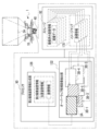
- the aircraft 10 includes a computer 12, a communication device 14, multiple propellers 16, multiple motors 18, a motor driver 20, and an input/output I/F 22.
- the computer 12 includes a processor 30, storage 32, and RAM34.
- Processor 30 , storage 32 , and RAM 34 are interconnected via bus 36 , and bus 36 is connected to input/output I/F 22 .
- the processor 30 has, for example, a CPU, and controls the aircraft 10 as a whole.
- the storage 32 is a nonvolatile storage device that stores various programs, various parameters, and the like. Examples of the storage 32 include HDDs and SSDs. Note that the HDD and SSD are merely examples, and flash memory, magnetoresistive memory, and/or ferroelectric memory may be used in place of or together with the HDD and/or SSD. .
- the RAM 34 is a memory that temporarily stores information, and is used by the processor 30 as a work memory. Examples of the RAM 34 include DRAM and/or SRAM.
- the communication device 14 is communicably connected to the imaging device 40 .
- the communication device 14 is wirelessly communicably connected to the imaging device 40 according to a predetermined wireless communication standard.
- the predefined wireless communication standard includes, for example, Bluetooth (registered trademark).
- wireless communication is exemplified here, the technology of the present disclosure is not limited to this, and wired communication may be applied instead of wireless communication.
- the communication device 14 is in charge of exchanging information with the imaging device 40 .
- the communication device 14 transmits information requested by the processor 30 to the imaging device 40 .
- the communication device 14 also receives information transmitted from the imaging device 40 and outputs the received information to the processor 30 via the bus 36 .
- Each propeller 16 is fixed to the rotating shaft of the motor 18.
- Each motor 18 rotates the propeller 16 .
- a plurality of motors 18 are connected to a motor driver 20 .
- Motor driver 20 is connected to processor 30 via input/output I/F 22 and bus 36 .
- Motor driver 20 individually controls multiple motors 18 according to instructions from processor 30 .
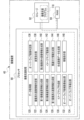
- the imaging device main body 42 includes a computer 52, a communication device 54, an image sensor 56, an image sensor driver 58, an imaging lens 60, a focus actuator 62, a zoom actuator 64, an aperture actuator 66, and a focus sensor 72. , a zoom sensor 74 , an aperture sensor 76 , a controller 78 , and an input/output I/F 80 .
- the computer 52 includes a processor 90 , storage 92 and RAM 94 .
- Processor 90 , storage 92 , and RAM 94 are interconnected via bus 96 , and bus 96 is connected to input/output I/F 80 .
- the computer 52 is an example of an “imaging support device” and a “computer” according to the technology of the present disclosure.
- the processor 90 is an example of a "processor" according to the technology of the present disclosure.
- the multiple hardware resources that implement the computer 12 shown in FIG.
- the multiple hardware resources that implement the computer 12 shown in FIG. it is the same as the specific example of the types of the processor 30, the storage 32, and the RAM 34), so a description thereof will be omitted.
- the types of the multiple hardware resources that implement the computer 52 are not necessarily the same as the types of the multiple hardware resources that implement the computer 12 shown in FIG. 2, and may be of different types. Needless to say.
- the processor 90 controls the entire imaging device 40 by cooperating with the storage 92 and the RAM 94 .
- the communication device 54 is communicably connected to the aircraft 10 .
- the communication device 54 is implemented by hardware resources similar to the communication device 14 (see FIG. 2) of the aircraft 10 .
- the communication device 54 is in charge of exchanging information with the aircraft 10 .
- communication device 54 transmits information to aircraft 10 in response to a request from processor 90 .
- Communication device 54 also receives information transmitted from aircraft 10 and outputs the received information to processor 90 via bus 96 .
- the sensor unit 44 includes an inertial sensor 98 , an inertial sensor driver 100 , a distance sensor 102 and a distance sensor driver 104 .
- Inertial sensor 98, inertial sensor driver 100, distance sensor 102, distance sensor driver 104, image sensor 56, image sensor driver 58, and controller 78 are connected to processor 90 via input/output I/F 80 and bus 96. .
- the inertial sensor 98 is connected to the inertial sensor driver 100.
- Inertial sensor driver 100 controls inertial sensor 98 according to instructions from processor 90 .
- the inertial sensor 98 detects the acceleration and angular velocity acting on the imaging device 40 under the control of the inertial sensor driver 100, and generates inertial data corresponding to the detected acceleration and angular velocity (for example, data indicating the acceleration itself and the angular velocity itself). data) to the processor 90 .
- the distance sensor 102 is connected to a distance sensor driver 104.
- Distance sensor driver 104 controls distance sensor 102 according to instructions from processor 90 .
- the distance sensor 102 measures, for example, the distance between the imaging target area 3A of the wall surface 2A (see FIG. 1) and the distance sensor 102, and outputs distance data corresponding to the measured distance. (for example, data indicating the distance itself) is output to the processor 90 .
- the image sensor 56 is connected with an image sensor driver 58 .
- Image sensor driver 58 controls image sensor 56 according to instructions from processor 90 .
- Image sensor 56 is, for example, a CMOS image sensor. Although a CMOS image sensor is exemplified as the image sensor 56 here, the technology of the present disclosure is not limited to this, and other image sensors may be used.
- the image sensor 56 captures an image of a subject (for example, the wall surface 2A of the target object 2) under the control of the image sensor driver 58, and outputs image data obtained by capturing the image to the processor 90.
- the imaging lens 60 is arranged on the subject side (object side) of the image sensor 56 .
- the imaging lens 60 captures subject light, which is reflected light from the subject, and forms an image of the captured subject light on the imaging surface of the image sensor 56 .
- the imaging lens 60 includes a plurality of optical elements (not shown) such as a focus lens, a zoom lens, and an aperture.
- the imaging lens 60 is connected to the computer 52 via the input/output I/F80.
- the plurality of optical elements included in the imaging lens 60 are connected to the input/output I/F 80 via a drive mechanism (not shown) having a power source.
- a plurality of optical elements included in imaging lens 60 operate under the control of computer 52 . In the imaging device 40, by operating a plurality of optical elements included in the imaging lens 60, adjustment of focus, optical zoom, shutter speed, etc. is realized.
- the storage 92 stores an imaging support program 118 .
- the imaging support program 118 is an example of a “program” according to the technology of the present disclosure.
- the processor 90 reads the imaging assistance program 118 from the storage 92 and executes the read imaging assistance program 118 on the RAM 94 .
- the processor 90 performs imaging support processing for synthesizing a plurality of images 162 (see FIG. 1) according to the imaging support program 118 executed on the RAM 94 .
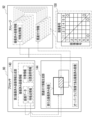
- the imaging support processing is performed by the processor 90 according to the imaging support program 118, the data acquisition unit 120, the captured image information determination unit 122, the first imaging device information generation unit 124, the second imaging device information generation unit 126, the first captured image Information generation unit 128, image map creation unit 130, overlap candidate image extraction unit 132, overlap rate derivation unit 134, overlap image determination unit 136, change instruction unit 138, second captured image information generation unit 140, image map It is realized by operating as the update unit 142 , the association information generation unit 144 , the composite image data generation unit 146 , and the movement instruction unit 148 .
- the data acquisition unit 120 acquires inertial data input from the inertial sensor 98 to the processor 90 and distance data input from the distance sensor 102 to the processor 90 .
- the storage 92 stores captured image information.
- the captured image information includes image data and the like.
- the storage 92 may or may not store captured image information. Therefore, the imaged image information determination unit 122 determines whether or not imaged image information is stored in the storage 92 .
- the first imaging device information generation unit 124 uses the inertia data and the distance data acquired by the data acquisition unit 120 as Based on this, the first imaging device information is generated.
- the first imaging device information includes position and orientation information and coordinate information.
- the position and orientation information includes position information indicating the position of the imaging device 40 and orientation information indicating the orientation of the imaging device 40 .
- the position and orientation information included in the first imaging device information is reference information that serves as a reference for the position and orientation information included in the second imaging device information, which will be described later. That is, the position of the imaging device 40 indicated by the position information in the position and orientation information included in the first imaging device information is set as the reference position at the origin of the first three-dimensional coordinate system set for the imaging device 40. be done.
- the orientation of the imaging device 40 indicated by the orientation information of the position and orientation information included in the first imaging device information is represented as a reference orientation by angles with respect to each coordinate axis of the above-described first three-dimensional coordinate system.
- the position and orientation information also includes distance information indicating the distance between the imaging target region 3A and the imaging device 40, and relative orientation information indicating the orientation of the imaging device 40 with respect to the imaging target region 3A.
- Distance information indicating the distance between the imaging target area 3A and the imaging device 40 is information corresponding to the distance data output from the distance sensor 102 .
- the attitude of the imaging device 40 with respect to the imaging target region 3A is represented by angles with respect to each coordinate axis of the second three-dimensional coordinate system set on the wall surface 2A (see FIG. 1) of the object 2.
- the coordinate information is information about the position of the imaging target area 3A.
- the coordinate information is information indicating the position of the imaging target area 3A, that is, information indicating the coordinates of the four vertices of the imaging target area 3A.
- the coordinate information is generated based on the position and orientation information, for example. That is, the coordinate information is based on position information indicating the position of the imaging device 40, distance information indicating the distance between the imaging target region 3A and the imaging device 40, posture information indicating the posture of the imaging device 40 with respect to the imaging target region 3A, and the like. generated by
- the imaging device 40 when generating the coordinate information, other position information about the position of the imaging device 40 is used instead of the position information indicating the position of the imaging device 40 or in addition to the position information indicating the position of the imaging device 40. may Further, when generating the coordinate information, instead of the distance information indicating the distance between the imaging target area 3A and the imaging device 40, or in addition to the distance information indicating the distance between the imaging target region 3A and the imaging device 40, the imaging Other distance information regarding the distance between the target area 3A and the imaging device 40 may be used.
- the imaging target region instead of the orientation information indicating the orientation of the imaging device 40 with respect to the imaging target region 3A, or in addition to the orientation information indicating the orientation of the imaging device 40 with respect to the imaging target region 3A, the imaging target region Other orientation information regarding the orientation of imaging device 40 relative to 3A may also be used.
- One of the four vertices of the imaging target area 3A indicated by the coordinate information included in the first imaging device information is set as the origin of the two-dimensional coordinate system set on the wall surface 2A of the object 2. be.
- the coordinates of the remaining three vertices of the four vertices of the imaging target area 3A indicated by the coordinate information included in the first imaging device information are relative coordinates with respect to the origin of the two-dimensional coordinate system described above.
- the second imaging device information generation unit 126 When the captured image information determination unit 122 determines that the captured image information is stored in the storage 92, the second imaging device information generation unit 126 combines the inertia data and the distance data acquired by the data acquisition unit 120. , and the first imaging device information generated by the first imaging device information generation unit 124, the second imaging device information is generated.
- the second imaging device information also includes position and orientation information and coordinate information, like the first imaging device information.
- the position and orientation information included in the second imaging device information is relative information with respect to the position and orientation information included in the first imaging device information. That is, the position of the imaging device 40 indicated by the position information included in the position and orientation information included in the second imaging device information is the position of the imaging device 40 indicated by the position information included in the position and orientation information included in the first imaging device information. is the position relative to the position of Also, the orientation of the imaging device 40 indicated by the orientation information included in the position and orientation information included in the second imaging device information is the orientation of the imaging device 40 indicated by the orientation information included in the position and orientation information included in the first imaging device information. It is the relative posture to the posture of
- the position and orientation information included in the second imaging device information also includes distance information indicating the distance between the imaging target region 3A and the imaging device 40, and the distance information indicating the distance between the imaging target region 3A and the imaging device 40, and the position and orientation information of the imaging device 40 with respect to the imaging target region 3A, similarly to the first imaging device information. and relative attitude information indicating the attitude.
- the coordinates of the four vertices of the imaging target area 3A indicated by the coordinate information included in the second imaging device information are relative coordinates with respect to the origin of the two-dimensional coordinate system set on the wall surface 2A of the object 2.
- the position of the imaging device 40 is, for example, a position based on the center of the image sensor 56 (see FIG. 3).
- the position of the imaging device 40 is calculated based on the acceleration specified from the inertia data, taking into consideration the positional deviation between the imaging device main body 42 and the sensor unit 44 .
- the attitude of the imaging device 40 is calculated based on the angular velocity indicated by the inertia data.
- the distance between the imaging target area 3A and the imaging device 40 is the distance based on the center of the image sensor 56, for example.
- the distance between the imaging target region 3A and the imaging device 40 is the distance specified from the distance data (that is, the distance between the imaging target region 3A and the distance sensor 102) in consideration of the positional deviation between the imaging device main body 42 and the sensor unit 44.
- the position information included in the position and orientation information is an example of "fourth position information” according to the technology of the present disclosure.
- the distance information included in the position and orientation information is an example of “distance information” according to the technology of the present disclosure.
- the relative orientation information included in the position and orientation information is an example of "attitude information” according to the technique of the present disclosure.
- the coordinate information included in the second imaging device information is an example of "second position information” and "third position information” according to the technology of the present disclosure.
- the first generated captured image information is stored in the storage 92, and an image map 170 including the coordinate information included in the first generated first imaging device information is stored in the storage 92. A state of being stored is shown.
- the first captured image information generation unit 128 outputs an image capturing instruction signal to the image sensor 56 to cause the image sensor 56 to capture an image of the target area 3A. Then, the first captured image information generation unit 128 generates the image data input from the image sensor 56 to the processor 90 and the position and orientation information included in the first imaging device information generated by the first imaging device information generation unit 124 . Based on and, imaged image information is generated.
- the imaged image information includes image data, feature point information, incidental information, and position and orientation information.
- the image data is image data representing an image obtained by imaging the imaging target region 3A by the image sensor 56 (hereinafter referred to as a “captured image”).
- the feature point information is information indicating coordinates of feature points included in the imaging target region 3A imaged by the image sensor 56 .
- the coordinates of the feature points are derived, for example, by subjecting the image data to image processing (for example, high-frequency component extraction processing, etc.).
- the coordinates of the feature point are, for example, coordinates based on any one of the four vertices of the imaging target region 3A.
- Supplementary information is, for example, information indicating focal length and/or resolution.
- the focal length is derived based on the position of the zoom lens within the imaging lens 60 (see FIG. 3).
- Resolution is derived based on the position of the focus lens within the imaging lens 60 (see FIG. 3).
- the position and orientation information is information generated by the first imaging device information generation unit 124 as described above.
- the captured image information generated by the first captured image information generation unit 128 is stored in the storage 92 .
- the image map creating unit 130 creates an image map 170 including the coordinate information included in the first imaging device information generated by the first imaging device information generating unit 124 .
- the image map 170 is formed by a plurality of pieces of coordinate information (see FIG. 7) when the imaging support processing proceeds.
- the image map 170 uses a plurality of pieces of coordinate information to form the coordinates of the four vertexes of the plurality of photographed regions 3B (see FIG. 1) corresponding to each piece of coordinate information, and thus the plurality of photographed images corresponding to each photographed region 3B. is an information group indicating the position of each.
- the image map 170 is an example of an "image map" according to the technology of the present disclosure.
- the image map 170 created by the image map creating unit 130 is stored in the storage 92.
- the coordinate information included in the image map 170 is stored in the storage 92 in association with the imaged image information generated by the first imaged image information generation unit 128 .
- the image map 170 may be information indicating relative positional relationships between a plurality of already-captured images.
- FIG. 7 shows a state in which a plurality of already-captured image information are stored in the storage 92 and the image map 170 includes a plurality of pieces of coordinate information as a result of progress of the imaging support processing. .
- the number of pieces of captured image information stored in the storage 92 and the number of pieces of coordinate information included in the image map 170 are both five.
- the captured image information stored first in the storage 92 among the plurality of captured image information is the captured image information generated by the above-described first captured image information generation unit 128 (see FIG. 6).
- the captured image information stored in the storage 92 after the second among the plurality of captured image information is the captured image generated by the second captured image information generation unit 140 (see FIG. 10) described later. Information.
- the coordinate information included in the image map 170 first among the plurality of pieces of coordinate information is the coordinate information included in the image map 170 by the above-described image map creation unit 130 (see FIG. 6). Further, the coordinate information included in the image map 170 after the second among the plurality of pieces of coordinate information is the coordinate information included in the image map 170 by the image map updating unit 142 (see FIG. 10) described later. Each piece of captured image information is associated with coordinate information. Image data included in each of the plurality of captured image information is image data representing a captured image.
- the overlap candidate image extracting unit 132 extracts a plurality of images based on a plurality of pieces of coordinate information included in the image map 170 and coordinate information included in the second image capturing device information generated by the second image capturing device information generating unit 126.
- a captured image that is a candidate for overlapping with the imaging target region 3A (hereinafter referred to as an “overlap candidate image”) is extracted from the captured images.
- the overlap candidate image extracting unit 132 extracts the coordinates of the four vertexes of the imaging target region 3A indicated by the coordinate information included in the second imaging device information, and the coordinates indicated by each coordinate information included in the image map 170.
- the coordinates of the four vertices of each captured area 3B are compared, and based on the comparison result, the captured area 3B overlapping the imaging target area 3A is extracted from the plurality of captured areas 3B.
- Each imaged area 3B corresponds to the imaged image indicated by the image data included in the imaged image information.
- the branch numbers 1 to 5 attached to the reference numerals of the imaged area 3B in FIG. 7 indicate the order in which the imaged area 3B is imaged.
- the first imaged area 3B (hereinafter also referred to as “imaged area 3B-1”) and the fifth imaged area 3B (hereinafter referred to as “imaged area 3B-5”) overlaps the imaging target region 3A, and the captured image corresponding to the first captured region 3B-1 and the fifth captured region
- imaged area 3B-5 overlaps the imaging target region 3A, and the captured image corresponding to the first captured region 3B-1 and the fifth captured region
- the captured image corresponding to 3B-5 is extracted as an overlap candidate image.
- a captured image is an example of a "captured image” according to the technology of the present disclosure.
- the image map 170 is an example of "first location information” according to the technology of the present disclosure.
- the overlap candidate image is an example of the "overlap candidate image” according to the technology of the present disclosure.
- the overlap rate derivation unit 134 derives the overlap rate between the imaging target region 3A and the overlap candidate image extracted by the overlap candidate image extraction unit 132. Specifically, the overlap rate derivation unit 134 calculates the overlap rate between the imaging target area 3A and the imaged area 3B corresponding to the overlap candidate image.
- imaging is performed based on the coordinates of the four vertices of the imaging target region 3A and the coordinates of the four vertices of the imaging completed region 3B.
- An overlap ratio between the target area 3A and the imaged area 3B is calculated.
- a live view image corresponding to the imaging target region 3A is acquired, and the result of comparing feature points between the live view image and the captured image is the overlap ratio between the imaging target region 3A and the captured region 3B.
- the overlap ratio between the imaging target area 3A and the first imaged area 3B-1 is calculated. Also, in the example shown in FIG. 8, the overlap ratio between the imaging target area 3A and the fifth imaged area 3B-5 is calculated.
- the overlap image determination unit 136 selects, among the overlap candidate images for which the overlap ratio is derived by the overlap ratio derivation unit 134, captured images having an overlap ratio equal to or higher than a predetermined overlap ratio (hereinafter referred to as “overlap It is determined whether or not there is a wrap image.
- the overlap image determination unit 136 determines that the overlap ratio of the imaged area 3B calculated by the overlap ratio derivation unit 134 with respect to the imaging target area 3A is equal to or greater than the predetermined overlap ratio. In this case, it is determined that the captured image corresponding to the captured area 3B is the overlap image. Further, if the overlap ratio of the imaged area 3B calculated by the overlap ratio derivation unit 134 with the imaging target area 3A is less than the default overlap ratio, the overlap image determination unit 136 determines that the overlap ratio is less than the predetermined overlap ratio. It is determined that the captured image corresponding to the completed area 3B is not an overlap image.
- the change instruction unit 138 generates a change instruction when the overlap image determination unit 136 determines that there is no overlap image.
- the change instruction is, for example, an instruction to change the position and/or orientation of the imaging device 40 in a direction and/or orientation in which the imaging target area 3A approaches the imaged area 3B corresponding to the overlap candidate image.
- the change instructing unit 138 changes the captured image corresponding to the image capturing target region 3A and the overlap candidate image based on the coordinate information corresponding to the image capturing target region 3A and the coordinate information corresponding to the overlap candidate image. Identify the positional relationship with the area 3B. In addition, the change instructing unit 138 determines the specified positional relationship, the position and orientation information included in the second imaging device information generated by the second imaging device information generation unit 126 corresponding to the imaging target region 3A, and the overlap candidate. The change instruction is generated based on the position and orientation information included in the captured image information stored in the storage 92 corresponding to the image. Then, the change instruction unit 138 outputs a change instruction signal indicating the generated change instruction to the aircraft 10, for example.
- the change instruction signal is an example of a "change instruction signal" according to the technology of the present disclosure.
- the flying object 10 changes the position and/or attitude of the flying object 10 by adjusting the number of rotations of the propellers 16 based on the change instruction signal input from the imaging device 40 .
- the position and/or orientation of the imaging device 40 is changed, which in turn changes the position of the imaging target region 3A by the imaging device 40 (for example, the position of the imaging target region 3A at 4 coordinates of one vertex) are changed.
- the change instruction unit 138 may output a change instruction signal to a transmitter (not shown) that transmits a flight instruction signal to the aircraft 10 and/or a base station (not shown).
- the change instruction indicated by the change instruction signal may be displayed on a display (not shown) provided in the transmitter. Further, the display may display a frame indicating the imaging target region 3A, a frame indicating the captured region 3B corresponding to the overlap candidate image, and the overlap ratio derived by the overlap ratio derivation unit 134. good.
- the transmitter may then transmit a flight instruction signal to the aircraft 10 based on the change instruction signal. Further, when the change instruction signal is output to the base station, the base station may transmit the flight instruction signal to the aircraft 10 based on the change instruction signal.
- the change instruction may be a change permission instruction that permits the change.
- the change permission instruction indicated by the change instruction signal may be displayed on a display (not shown) provided in the transmitter. Further, the display may display a frame indicating the imaging target region 3A, a frame indicating the captured region 3B corresponding to the overlap candidate image, and the overlap ratio derived by the overlap ratio derivation unit 134. good. Then, the transmitter may transmit a flight instruction signal to the aircraft 10 based on a command given to the transmitter by the user based on the change permission instruction displayed on the display.
- the second captured image information generation unit 140 outputs an image capturing instruction signal to the image sensor 56 when the overlap image determination unit 136 determines that an overlap image exists. This causes the image sensor 56 to pick up an image of the imaging target area 3A. Then, the second captured image information generation unit 140 generates the image data input from the image sensor 56 to the processor 90 and the position and orientation information included in the second imaging device information generated by the second imaging device information generation unit 126. Based on and, imaged image information is generated.
- the imaged image information generated by the second imaged image information generation unit 140 is the same as the imaged image information generated by the first imaged image information generation unit 128, and includes image data, feature point information, and incidental information. , and pose information.
- the captured image information generated by the second captured image information generation unit 140 is stored in the storage 92 .
- the imaging instruction signal output to the image sensor 56 by the second captured image information generation unit 140 is an example of the "first signal” and the "imaging instruction signal" according to the technology of the present disclosure.
- the imaging instruction signal may be output to a transmitter (not shown) and/or a base station (not shown) that transmits the flight instruction signal to the aircraft 10 . Further, when an imaging instruction signal is output to the transmitter, the imaging instruction indicated by the imaging instruction signal may be displayed on a display (not shown) provided in the transmitter. Then, the transmitter may transmit the imaging instruction signal to the imaging device 40 . Further, when the imaging instruction signal is output to the base station, the base station may transmit the imaging instruction signal to the imaging device 40 based on the imaging instruction signal.
- the imaging instruction may be an imaging permission instruction that permits imaging.
- the imaging instruction signal When the imaging instruction signal is output to the transmitter, the imaging permission instruction indicated by the imaging instruction signal may be displayed on a display (not shown) provided in the transmitter. Then, the transmitter may transmit the imaging instruction signal to the imaging device 40 based on the command given to the transmitter by the user based on the imaging permission instruction displayed on the display.
- the image map updating unit 142 acquires the coordinate information included in the second imaging device information generated by the second imaging device information generation unit 126. Then, the image map update unit 142 updates the image map 170 by including the acquired coordinate information in the image map 170 .
- the coordinate information included in the image map 170 is stored in the storage 92 in association with the imaged image information generated by the second imaged image information generating section 140 .
- association information generation unit 144 determines that the image data included in the captured image information generated by the captured image information generated by the second captured image information generation unit 140 is indicated by the captured image that is the overlap image.
- Association information is generated that is information that associates the two captured images with a captured image (that is, a new captured image).
- the association information generation unit 144 stores in the storage 92 corresponding to the feature point information included in the captured image information generated by the second captured image information generation unit 140 and the overlapping image. Feature point information included in captured image information is acquired. Then, the association information generation unit 144 extracts the feature points commonly included in the two captured images based on the acquired two pieces of feature point information, and generates association information including information indicating the extracted feature points. do.
- the association information generated by the association information generation unit 144 is stored in the storage 92 in association with captured image information corresponding to each of the two captured images.
- FIG. 11 shows a table 150 that schematically shows the relationship between a plurality of pieces of association information stored in the storage 92 and a plurality of pieces of captured image information stored in the storage 92 .
- the "image number" shown in the table 150 indicates the order in which the multiple captured images were obtained.
- “ ⁇ (circle symbol)” shown in the table 150 indicates that there is association information corresponding to the captured image
- “blank” in the table 150 indicates association information corresponding to the captured image. does not exist.
- the table 150 indicates that there is association information that associates the first captured image and the sixth captured image.
- the table 150 also indicates that there is association information that associates the fifth captured image and the sixth captured image.
- a captured image that is an overlap image is an example of a "first captured image” according to the technology of the present disclosure.
- a captured image indicated by image data included in captured image information generated by the second captured image information generation unit 140 is an example of a “second captured image”.
- the association information is an example of "association information" according to the technology of the present disclosure.
- Information indicating feature points extracted by the association information generation unit 144 is an example of "feature point information” relating to the technology of the present disclosure.
- the composite image data generation unit 146 acquires a plurality of imaged image information and a plurality of association information from the storage 92 . Then, the composite image data generation unit 146 generates composite image data representing the composite image 160 based on the image data included in the multiple captured image information and the multiple pieces of association information.
- the composite image 160 is the captured images corresponding to the association information (that is, the captured images partially overlapping each other) for the plurality of captured images indicated by the image data included in the plurality of captured image information.
- is an image obtained by synthesizing Synthetic image 160 is, for example, a panoramic image.
- Synthetic image 160 is an example of a “synthetic image” according to the technology of the present disclosure.
- FIG. 12 shows how a composite image 160 is generated from a plurality of images 162 .
- Each image 162 is a captured image indicated by image data included in the captured image information.
- the movement instruction unit 148 outputs a movement instruction signal indicating a movement instruction to the flying object 10 .
- a new area of the wall surface 2A (see FIG. 1) is set as the imaging target area 3A by moving the flying object 10 based on the movement instruction signal.
- the movement instructing unit 148 extracts an area of the wall surface 2A that has not been imaged based on a plurality of pieces of coordinate information included in the image map 170, and moves the imaging device 40 to the position where the extracted area is the imaging target area 3A. (i.e., a position specifying instruction specifying a position to move) may be generated.
- a movement instruction signal indicating a position designation instruction is input to the flying object 10
- the flying object 10 flies according to the movement instruction signal, thereby moving the imaging device 40 to the position designated by the position designation instruction. good.
- the movement instruction unit 148 may output a movement instruction signal to a transmitter (not shown) and/or a base station (not shown) that transmits a flight instruction signal to the aircraft 10 .
- a transmitter not shown
- a base station not shown
- the movement instruction indicated by the movement instruction signal may be displayed on a display (not shown) provided in the transmitter.
- the transmitter may then transmit a flight instruction signal to the aircraft 10 .
- the base station may transmit the flight instruction signal to the aircraft 10 based on the movement instruction signal.
- the movement instruction may be a movement permission instruction that permits movement.
- a movement instruction signal When a movement instruction signal is output to the transmitter, a movement permission instruction indicated by the movement instruction signal may be displayed on a display (not shown) provided in the transmitter.
- the display may also display a composite image 160 that includes multiple images 162 .
- the transmitter may transmit a flight instruction signal to the aircraft 10 based on a command given to the transmitter by the user based on the movement permission instruction displayed on the display.
- FIG. 13 shows an example of the flow of imaging support processing according to this embodiment.
- step ST10 the data acquisition unit 120 acquires inertial data input from the inertial sensor 98 to the processor 90 and distance data input from the distance sensor 102 to the processor 90. (see Figure 5). After the process of step ST10 is executed, the imaging support process proceeds to step ST12.
- step ST12 the captured image information determination unit 122 determines whether captured image information related to the captured image is stored in the storage 92 (see FIG. 5). In step ST12, if the captured image information is not stored in the storage 92, the determination is negative, and the imaging support process proceeds to step ST14. In step ST12, if the captured image information is stored in the storage 92, the determination is affirmative, and the imaging support process proceeds to step ST20.
- step ST14 the first imaging device information generation unit 124 generates first imaging device information including position/orientation information and coordinate information regarding the imaging device 40 based on the inertia data and distance data acquired in step ST10 ( See Figure 5). After the process of step ST14 is executed, the imaging support process proceeds to step ST16.
- step ST16 the first captured image information generation unit 128 causes the image sensor 56 mounted on the imaging device 40 to capture an image of the imaging target region 3A. Then, the first captured image information generation unit 128 performs image capturing based on the image data input from the image sensor 56 to the processor 90 and the position and orientation information included in the first image capturing device information generated in step ST14. Captured image information about the captured image is generated (see FIG. 6). The captured image information is stored in the storage 92 . After the process of step ST16 is executed, the imaging support process proceeds to step ST18.
- the image map creating section 130 creates an image map 170 including the coordinate information included in the first imaging device information generated at step ST14 (see FIG. 6).
- the coordinate information included in the image map 170 is stored in the storage 92 in association with the imaged image information generated by the first imaged image information generation unit 128 .
- the imaging support process proceeds to step ST10.
- step ST20 the second imaging device information generation unit 126 generates position and orientation information about the imaging device 40 based on the inertia data and distance data acquired in step ST10 and the first imaging device information generated in step ST14. and second imaging device information including coordinate information (see FIG. 5).
- the imaging support process proceeds to step ST22.
- step ST22 the overlap candidate image extraction unit 132 extracts images of objects to be imaged by the imaging device 40 based on the coordinate information included in the image map 170 and the coordinate information included in the second imaging device information generated in step ST20.
- An overlap candidate image that is a candidate for overlapping with the area 3A is extracted (see FIG. 7).
- step ST22 of the first time a captured image corresponding to one captured image information stored in the storage 92 is extracted as an overlap candidate image.
- step ST ⁇ b>22 for the second and subsequent times overlap candidate images are extracted from a plurality of captured images corresponding to each of the plurality of captured image information stored in the storage 92 .
- step ST24 the overlap rate derivation unit 134 derives the overlap rate between the imaging target area 3A by the imaging device 40 and the overlap candidate image extracted at step ST22 (see FIG. 8). After the process of step ST24 is executed, the imaging support process proceeds to step ST26.
- step ST26 the overlap image determination unit 136 determines whether or not there is an overlap image whose overlap ratio is equal to or higher than the default overlap ratio among the overlap candidate images for which the overlap ratio has been derived in step ST24. (See FIG. 9). In step ST26, if there is no overlapping image, the determination is negative, and the imaging support process proceeds to step ST28. In step ST26, if there is an overlapping image, the determination is affirmative, and the imaging support process proceeds to step ST30.
- step ST28 the change instructing unit 138 changes the imaging device based on the coordinate information included in the second imaging device information generated in step ST20 and the coordinate information corresponding to the overlap candidate image extracted in step ST22.
- a change instruction is generated, which is an instruction to change the position and/or orientation of 40 (see FIG. 9).
- the change instruction unit 138 outputs a change instruction signal indicating the generated change instruction to the aircraft 10, for example.
- the position and/or orientation of the flying object 10 is changed, thereby changing the position and/or orientation of the imaging device 40, which in turn changes the position of the imaging target region 3A by the imaging device 40 (for example, the imaging target region 3A) are changed.
- the imaging support process proceeds to step ST10.
- step ST30 the second imaged image information generating section 140 causes the image sensor 56 to image the imaging target region 3A (see FIG. 10). Then, the second imaged image information generation unit 140 performs imaging based on the image data input from the image sensor 56 to the processor 90 and the position and orientation information included in the second imaging device information generated in step ST20. Generate finished image information. The captured image information is stored in the storage 92 . After the process of step ST30 is executed, the imaging support process proceeds to step ST32.
- step ST32 the image map updating unit 142 acquires the coordinate information included in the second imaging device information generated in step ST20, and updates the image map 170 by including the acquired coordinate information in the image map 170. (See FIG. 10).
- the coordinate information included in the image map 170 is stored in the storage 92 in association with the imaged image information generated by the second imaged image information generating section 140 .
- the imaging support process proceeds to step ST34.
- step ST34 the association information generation unit 144 compares the captured image determined to be the overlapping image in step ST26 with the captured image indicated by the image data included in the captured image information generated in step ST30.
- Association information which is information for associating two captured images, is generated (see FIG. 11).
- the association information is stored in the storage 92 in association with captured image information corresponding to each of the two captured images.
- the composite image data generation unit 146 acquires a plurality of imaged image information and a plurality of association information from the storage 92 (see FIG. 12). Then, the composite image data generation unit 146 generates composite image data based on the image data included in the multiple captured image information and the multiple pieces of association information. As a result, a composite image 160 represented by the composite image data is obtained.
- the imaging support process proceeds to step ST38.
- the movement instruction unit 148 outputs a movement instruction signal indicating a movement instruction to the aircraft 10 (see FIG. 12).
- a new area of the wall surface 2A (see FIG. 1) is set as the imaging target area 3A as the flying object 10 moves.
- the processor 90 determines whether or not the condition for ending the imaging support process is satisfied.
- conditions for ending the imaging support process include a condition that the user ends the imaging support process, a condition that the number of captured images reaches the number specified by the user, and the like.
- the determination is negative, and the imaging support process proceeds to step ST10.
- the determination is affirmative, and the imaging support processing ends.
- the imaging support method described as the operation of the flight imaging device 1 described above is an example of the "imaging support method" according to the technology of the present disclosure.
- the processor 90 performs the Overlap candidate images, which are candidates for overlapping with the imaging target area 3A by the imaging device 40, are extracted from the plurality of already-captured images (see FIG. 7). Then, the overlap ratio between the imaging target region 3A and the overlap candidate image is derived (see FIG. 8). An imaging instruction signal is output (see FIG. 10). Therefore, for example, compared to the case where the imaging target region 3A whose overlap rate with the captured image is equal to or higher than the predetermined overlap rate is determined in the order in which the multiple captured images are obtained, It is possible to determine with a high degree of freedom the imaging target region 3A whose overlap rate is equal to or higher than the predetermined overlap rate.
- the processor 90 extracts overlap candidate images, which are candidates for overlapping with the imaging target region 3A by the imaging device 40, from a plurality of captured images (see FIG. 7), and An overlap ratio with the overlap candidate image is derived (see FIG. 8). Therefore, for example, the load on the processor 90 can be reduced compared to the case where the overlap ratio between the imaging target region 3A and the multiple captured images is derived.
- the storage 92 also stores an image map 170 indicating the position of each of the multiple captured images (see FIG. 7). Therefore, based on the image map 170, it is possible to extract overlap candidate images, which are candidates for overlapping with the imaging target area 3A by the imaging device 40, from a plurality of already-captured images.
- the processor 90 when the overlap ratio is equal to or higher than the predetermined overlap ratio, the processor 90 outputs an imaging instruction signal instructing the image sensor 56 of the imaging device 40 to image the imaging target region 3A (see FIG. 10). ). Therefore, when the overlap rate is equal to or higher than the predetermined overlap rate, a new captured image can be obtained by capturing an image of the imaging target region 3A with the image sensor 56 .
- the processor 90 stores captured image information (that is, the second captured image) corresponding to the new captured image.
- the image map 170 is updated based on the coordinate information included in the captured image information generated by the image information generation unit 140 (see FIG. 10). Therefore, when the image map 170 is updated, based on the updated image map 170, it is possible to extract overlap candidate images that are candidates for overlapping with the imaging target region 3A by the imaging device 40.
- FIG. 10 illustrates the image map 170 based on the updated image map 170.
- the processor 90 also captures a captured image that is an overlap candidate image having an overlap rate equal to or higher than a predetermined overlap rate, and a captured image obtained by capturing an image with the image sensor 56 in accordance with the imaging instruction signal. to generate association information that associates the two captured images (see FIG. 11). Therefore, two captured images can be synthesized based on the association information.
- the association information also includes feature point information regarding feature points commonly included in two captured images (see FIG. 11). Therefore, two captured images can be synthesized based on the common feature points indicated by the feature point information.
- the processor 90 generates a synthesized image 160 by synthesizing the two captured images based on the association information (see FIG. 12). Therefore, for example, it is possible to generate a composite image 160 with higher precision than when two captured images are composited without based on the association information.
- the processor 90 extracts overlap candidate images based on the image map 170 regarding the position of each of the multiple captured images and the coordinate information regarding the position of the imaging target area 3A (see FIG. 7). Therefore, overlap candidate images can be extracted by comparing the coordinates of the four vertices of the captured area 3B corresponding to each captured image with the coordinates of the four vertices of the captured area 3A.
- the coordinate information regarding the position of the imaging target area 3A includes position information indicating the position of the imaging device 40, distance information indicating the distance between the imaging target region 3A and the imaging device 40, and coordinate information indicating the position of the imaging device 40 with respect to the imaging target region 3A.
- This is information generated based on posture information indicating a posture. Therefore, it is possible to obtain the position of the imaging device 40, the distance between the imaging target region 3A and the imaging device 40, and the position of the imaging target region 3A corresponding to the attitude of the imaging device 40 with respect to the imaging target region 3A.
- the processor 90 outputs a change instruction signal indicating an instruction to change the position and/or attitude of the imaging device 40 to the aircraft 10 (see FIG. 9). reference). Therefore, the position and/or attitude of the flying object 10 is changed based on the change instruction signal, and the position and/or attitude of the imaging device 40 is changed, so that the position ( For example, the coordinates of the four vertices of the imaging target area 3A) can be changed.
- the processor 90 generates a change instruction signal based on the image map 170 regarding the position of each of the multiple captured images and the coordinate information regarding the position of the imaging target area 3A (see FIG. 9). Therefore, the position and/or orientation of the imaging device 40 can be changed based on the relative positional relationship between the position of each of the multiple captured images and the position of the imaging target region 3A.
- the processor 90 of the imaging device 40 generates synthetic image data representing the synthetic image 160 based on image data included in the plurality of captured image information stored in the storage 92 (see FIG. 12). reference).
- a plurality of image data is input from the processor 90 of the imaging device 40 to the processor 210 of the image processing device 200 communicably connected to the imaging device 40 by wired connection or wireless connection.
- the processor 210 of the image processing device 200 may generate the composite image data based on the plurality of input image data.
- the processor 210 is an example of a “synthesis processor” according to the technology of the present disclosure.
- the processor 90 and the processor 210 are examples of the "processor" according to the technology of the present disclosure.
- the processor 90 of the imaging device 40 does not need to generate synthetic image data, so the load on the processor 90 is reduced compared to the case where the processor 90 of the imaging device 40 generates synthetic image data. can do.
- the coordinate information that is the information regarding the position of the imaging target area 3A is used (see FIG. 7).
- information regarding the position of the imaging device 40 may be used.
- the image map 170 including coordinate information is used as the information regarding the position of each of a plurality of captured images (see FIG. 7).
- information in a system different from the image map 170 may be used.
- the multiple captured images are acquired by the imaging device 40, but the multiple captured images may be acquired by an imaging device other than the imaging device 40. Then, an overlap candidate image, which is a candidate for overlapping with the imaging target area of the imaging device 40, may be extracted from a plurality of captured images acquired by other imaging devices.
- processor 90 is illustrated in each of the above embodiments, at least one other CPU, at least one GPU, and/or at least one TPU may be used in place of or together with the processor 90 can be
- the imaging support program 118 may be stored in a portable non-temporary computer-readable storage medium such as an SSD or USB memory (hereinafter simply referred to as "non-temporary storage medium").
- the imaging assistance program 118 stored in the non-temporary storage medium is installed in the computer 52 of the imaging device 40, and the processor 90 executes processing according to the imaging assistance program 118.
- the image capturing support program 118 is stored in a storage device such as another computer or server device connected to the image capturing apparatus 40 via a network, and the image capturing support program 118 is downloaded in response to a request from the image capturing apparatus 40. It may be installed on computer 52 .
- imaging support program 118 it is not necessary to store all of the imaging support program 118 in a storage device such as another computer or server device connected to the imaging device 40, or in the storage 92, and a part of the imaging support program 118 may be stored. You can leave it.
- the computer 52 is built into the imaging device 40, the technology of the present disclosure is not limited to this, and the computer 52 may be provided outside the imaging device 40, for example.
- the computer 52 including the processor 90, the storage 92, and the RAM 94 is illustrated in each of the above-described embodiments, the technology of the present disclosure is not limited to this, and instead of the computer 52, an ASIC, FPGA, and/or Or you may apply the device containing PLD. Also, instead of the computer 52, a combination of hardware configuration and software configuration may be used.
- processors can be used as hardware resources for executing the various processes described in each of the above embodiments.
- processors include CPUs, which are general-purpose processors that function as hardware resources that execute various processes by executing software, that is, programs.
- processors include, for example, dedicated electronic circuits such as FPGAs, PLDs, and ASICs, which are processors having circuit configurations specially designed to execute specific processing.
- a memory is built in or connected to each processor, and each processor uses the memory to perform various processes.
- Hardware resources that perform various processes may be configured with one of these various processors, or a combination of two or more processors of the same or different types (for example, a combination of multiple FPGAs or CPUs). and FPGA). Also, the hardware resource for executing various processes may be one processor.
- one processor is configured by combining one or more CPUs and software, and this processor functions as a hardware resource that executes various processes.
- this processor functions as a hardware resource that executes various processes.
- SoC SoC, etc.
- a and/or B is synonymous with “at least one of A and B.” That is, “A and/or B” means that only A, only B, or a combination of A and B may be used. Also, in this specification, when three or more matters are expressed by connecting with “and/or”, the same idea as “A and/or B" is applied.
Landscapes
- Engineering & Computer Science (AREA)
- Multimedia (AREA)
- Signal Processing (AREA)
- Studio Devices (AREA)
- Image Analysis (AREA)
- Apparatus For Radiation Diagnosis (AREA)
- Image Processing (AREA)
Priority Applications (4)
| Application Number | Priority Date | Filing Date | Title |
|---|---|---|---|
| JP2023570713A JPWO2023127313A1 (https=) | 2021-12-28 | 2022-11-07 | |
| CN202280085828.4A CN118435617A (zh) | 2021-12-28 | 2022-11-07 | 摄像辅助装置、摄像辅助方法及程序 |
| DE112022006206.1T DE112022006206T5 (de) | 2021-12-28 | 2022-11-07 | Bildgebungsunterstützungsvorrichtung, Bildgebungsunterstützungsverfahren und Programm |
| US18/736,492 US12538032B2 (en) | 2021-12-28 | 2024-06-06 | Imaging support device, imaging support method, and program |
Applications Claiming Priority (2)
| Application Number | Priority Date | Filing Date | Title |
|---|---|---|---|
| JP2021214957 | 2021-12-28 | ||
| JP2021-214957 | 2021-12-28 |
Related Child Applications (1)
| Application Number | Title | Priority Date | Filing Date |
|---|---|---|---|
| US18/736,492 Continuation US12538032B2 (en) | 2021-12-28 | 2024-06-06 | Imaging support device, imaging support method, and program |
Publications (1)
| Publication Number | Publication Date |
|---|---|
| WO2023127313A1 true WO2023127313A1 (ja) | 2023-07-06 |
Family
ID=86998721
Family Applications (1)
| Application Number | Title | Priority Date | Filing Date |
|---|---|---|---|
| PCT/JP2022/041380 Ceased WO2023127313A1 (ja) | 2021-12-28 | 2022-11-07 | 撮像支援装置、撮像支援方法、及びプログラム |
Country Status (5)
| Country | Link |
|---|---|
| US (1) | US12538032B2 (https=) |
| JP (1) | JPWO2023127313A1 (https=) |
| CN (1) | CN118435617A (https=) |
| DE (1) | DE112022006206T5 (https=) |
| WO (1) | WO2023127313A1 (https=) |
Cited By (1)
| Publication number | Priority date | Publication date | Assignee | Title |
|---|---|---|---|---|
| JP7788025B1 (ja) * | 2025-04-01 | 2025-12-17 | 株式会社 日立産業制御ソリューションズ | 画像処理装置、画像処理システム、及び画像処理方法 |
Families Citing this family (1)
| Publication number | Priority date | Publication date | Assignee | Title |
|---|---|---|---|---|
| CN116648666B (zh) * | 2020-12-25 | 2026-04-10 | 富士胶片株式会社 | 透镜装置、摄像装置、透镜装置的动作方法、摄像装置的动作方法及存储介质 |
Citations (2)
| Publication number | Priority date | Publication date | Assignee | Title |
|---|---|---|---|---|
| WO2018180214A1 (ja) * | 2017-03-28 | 2018-10-04 | 富士フイルム株式会社 | 画像処理装置、カメラ装置、および画像処理方法 |
| WO2020008973A1 (ja) * | 2018-07-03 | 2020-01-09 | 富士フイルム株式会社 | 撮影計画提示装置および方法 |
Family Cites Families (14)
| Publication number | Priority date | Publication date | Assignee | Title |
|---|---|---|---|---|
| JP4622797B2 (ja) | 2005-10-11 | 2011-02-02 | パナソニック株式会社 | 画像合成装置及び画像合成方法 |
| JP2007174301A (ja) | 2005-12-22 | 2007-07-05 | Toshiba Corp | 画像撮影装置 |
| JP4803155B2 (ja) | 2007-10-15 | 2011-10-26 | セイコーエプソン株式会社 | 複数の画像データのパノラマ合成 |
| JP5248951B2 (ja) | 2008-08-12 | 2013-07-31 | ソニーモバイルコミュニケーションズ, エービー | カメラ装置、画像撮影支援装置、画像撮影支援方法、及び画像撮影支援プログラム |
| JP5190712B2 (ja) * | 2009-03-24 | 2013-04-24 | アイシン精機株式会社 | 障害物検出装置 |
| JP5596972B2 (ja) | 2009-12-28 | 2014-10-01 | キヤノン株式会社 | 撮像装置の制御装置および制御方法 |
| WO2012086821A1 (ja) * | 2010-12-20 | 2012-06-28 | 日本電気株式会社 | 測位装置、測位方法 |
| JP6071289B2 (ja) * | 2012-07-09 | 2017-02-01 | キヤノン株式会社 | 画像処理装置、画像処理方法、およびプログラム |
| JP2014115896A (ja) | 2012-12-11 | 2014-06-26 | Canon Inc | 画像処理装置、画像処理方法およびプログラム |
| JP6441586B2 (ja) | 2014-04-25 | 2018-12-19 | 国立大学法人 東京大学 | 情報処理装置および情報処理方法 |
| EP3418726A4 (en) * | 2016-02-19 | 2019-03-20 | SCREEN Holdings Co., Ltd. | DEFECT DETECTION DEVICE, DEFECT DETECTION METHOD AND PROGRAM |
| WO2018003074A1 (ja) * | 2016-06-30 | 2018-01-04 | 楽天株式会社 | 画像処理装置、画像処理方法、および、画像処理プログラム |
| JP7286968B2 (ja) | 2019-01-09 | 2023-06-06 | 凸版印刷株式会社 | 画像撮像支援装置及び画像撮像支援方法 |
| US20240331418A1 (en) * | 2021-09-29 | 2024-10-03 | Nec Corporation | Image processing device, image processing method, and recording medium |
-
2022
- 2022-11-07 WO PCT/JP2022/041380 patent/WO2023127313A1/ja not_active Ceased
- 2022-11-07 JP JP2023570713A patent/JPWO2023127313A1/ja active Pending
- 2022-11-07 CN CN202280085828.4A patent/CN118435617A/zh active Pending
- 2022-11-07 DE DE112022006206.1T patent/DE112022006206T5/de active Pending
-
2024
- 2024-06-06 US US18/736,492 patent/US12538032B2/en active Active
Patent Citations (2)
| Publication number | Priority date | Publication date | Assignee | Title |
|---|---|---|---|---|
| WO2018180214A1 (ja) * | 2017-03-28 | 2018-10-04 | 富士フイルム株式会社 | 画像処理装置、カメラ装置、および画像処理方法 |
| WO2020008973A1 (ja) * | 2018-07-03 | 2020-01-09 | 富士フイルム株式会社 | 撮影計画提示装置および方法 |
Cited By (1)
| Publication number | Priority date | Publication date | Assignee | Title |
|---|---|---|---|---|
| JP7788025B1 (ja) * | 2025-04-01 | 2025-12-17 | 株式会社 日立産業制御ソリューションズ | 画像処理装置、画像処理システム、及び画像処理方法 |
Also Published As
| Publication number | Publication date |
|---|---|
| JPWO2023127313A1 (https=) | 2023-07-06 |
| US12538032B2 (en) | 2026-01-27 |
| CN118435617A (zh) | 2024-08-02 |
| US20240323542A1 (en) | 2024-09-26 |
| DE112022006206T5 (de) | 2024-11-07 |
Similar Documents
| Publication | Publication Date | Title |
|---|---|---|
| JP6921686B2 (ja) | 生成装置、生成方法、及びプログラム | |
| JP6962775B2 (ja) | 情報処理装置、空撮経路生成方法、プログラム、及び記録媒体 | |
| US12538032B2 (en) | Imaging support device, imaging support method, and program | |
| US11122215B2 (en) | Imaging apparatus, unmanned moving object, imaging method, system, and program | |
| CN112985359B (zh) | 影像获取方法及影像获取设备 | |
| JP6685814B2 (ja) | 撮像装置およびその制御方法 | |
| JP2019028560A (ja) | モバイルプラットフォーム、画像合成方法、プログラム、及び記録媒体 | |
| CN110023988A (zh) | 用于生成道路的组合俯视图像的方法和系统 | |
| CN110892354A (zh) | 图像处理方法和无人机 | |
| CN109891188B (zh) | 移动平台、摄像路径生成方法、程序、以及记录介质 | |
| US20250024132A1 (en) | Imaging control apparatus, imaging control method, and program | |
| JP6997164B2 (ja) | 画像処理装置、画像処理方法、プログラム、及び記録媒体 | |
| JP6790318B2 (ja) | 無人航空機、制御方法、及びプログラム | |
| JP4809134B2 (ja) | 画像処理装置及びその処理方法 | |
| KR101323099B1 (ko) | 모자이크 영상 생성 장치 | |
| JP2005063129A (ja) | 時系列画像からのテクスチャ画像獲得方法,テクスチャ画像獲得装置,テクスチャ画像獲得プログラムおよびそのプログラムを記録した記録媒体 | |
| WO2023135910A1 (ja) | 撮像装置、撮像方法、及びプログラム | |
| JP2023072355A (ja) | 飛行体の撮影場所決定装置、飛行体の撮影場所決定方法及び飛行体の撮影場所決定プログラム | |
| JP7585358B2 (ja) | 情報処理システム、方法及びプログラム | |
| JP6896963B1 (ja) | 制御装置、撮像装置、移動体、制御方法、及びプログラム | |
| JP6569157B1 (ja) | 制御装置、撮像装置、移動体、制御方法、及びプログラム | |
| JP2020010213A (ja) | 情報処理装置、撮像装置の姿勢の設定方法及びプログラム | |
| WO2023195394A1 (ja) | 撮像支援装置、移動体、撮像支援方法、及びプログラム | |
| CN119563327A (zh) | 控制装置、控制方法及程序 | |
| JP2024064155A (ja) | 映像合成用フレーム生成装置、映像合成装置及びプログラム |
Legal Events
| Date | Code | Title | Description |
|---|---|---|---|
| 121 | Ep: the epo has been informed by wipo that ep was designated in this application |
Ref document number: 22915545 Country of ref document: EP Kind code of ref document: A1 |
|
| WWE | Wipo information: entry into national phase |
Ref document number: 2023570713 Country of ref document: JP |
|
| WWE | Wipo information: entry into national phase |
Ref document number: 202280085828.4 Country of ref document: CN |
|
| WWE | Wipo information: entry into national phase |
Ref document number: 112022006206 Country of ref document: DE |
|
| 122 | Ep: pct application non-entry in european phase |
Ref document number: 22915545 Country of ref document: EP Kind code of ref document: A1 |