WO2023127313A1 - Image capture supporting device, image capture supporting method, and program - Google Patents
Image capture supporting device, image capture supporting method, and program Download PDFInfo
- Publication number
- WO2023127313A1 WO2023127313A1 PCT/JP2022/041380 JP2022041380W WO2023127313A1 WO 2023127313 A1 WO2023127313 A1 WO 2023127313A1 JP 2022041380 W JP2022041380 W JP 2022041380W WO 2023127313 A1 WO2023127313 A1 WO 2023127313A1
- Authority
- WO
- WIPO (PCT)
- Prior art keywords
- image
- imaging
- information
- imaging device
- overlap
- Prior art date
Links
Images


Classifications
-
- H—ELECTRICITY
- H04—ELECTRIC COMMUNICATION TECHNIQUE
- H04N—PICTORIAL COMMUNICATION, e.g. TELEVISION
- H04N23/00—Cameras or camera modules comprising electronic image sensors; Control thereof
- H04N23/60—Control of cameras or camera modules
-
- H—ELECTRICITY
- H04—ELECTRIC COMMUNICATION TECHNIQUE
- H04N—PICTORIAL COMMUNICATION, e.g. TELEVISION
- H04N23/00—Cameras or camera modules comprising electronic image sensors; Control thereof
- H04N23/60—Control of cameras or camera modules
- H04N23/698—Control of cameras or camera modules for achieving an enlarged field of view, e.g. panoramic image capture
Definitions
- the technology of the present disclosure relates to an imaging support device, an imaging support method, and a program.
- Japanese Patent Application Laid-Open No. 2010-045587 discloses an image capturing unit for capturing an image, an image display unit having at least a screen for displaying an image, and a shake detection unit for detecting device shake during image capturing by the image capturing unit.
- an image recording unit for recording information of an image captured by the image capturing unit; a capturing range of a first image captured immediately before by the image capturing unit and recorded in the image recording unit; a relative relationship calculation unit that obtains a degree of relative relationship parameter that represents at least a relative positional relationship between one image and a shooting range of a second image that is shot by the image shooting unit after the first image; a display control unit for generating an image for clarifying the relative positional relationship between the photographing ranges from the relative relationship parameter obtained by and displaying the image together with the second image on the screen of the image display unit and an overlap calculation unit that obtains a degree of overlap parameter representing a degree of overlap between the photographing range of the first image and the photographing range of the second image;
- the notifying unit that gives a predetermined notification to the user and the redundancy parameter obtained by the overlap calculating unit are within a predetermined threshold range, and from the detection output of the shake detecting unit, the apparatus shake during image capturing by the image capturing unit is substantially
- Japanese Unexamined Patent Application Publication No. 2020-113843 discloses an image capturing support device that supports capturing of multi-viewpoint images used to restore a three-dimensional shape model of a target object, and includes image data captured immediately before the target object.
- a feature point extraction unit for extracting feature points in the captured image data and the preview image data
- a matching processing unit for detecting first corresponding points of the feature points in the captured image data and the preview image data
- An imaging assistance device includes an assistance information notification unit that displays a preview image of preview image data on which dots are superimposed, and notifies assistance information corresponding to imaging in the preview image.
- Japanese Patent Application Laid-Open No. 2011-139368 discloses that a subject having a larger angle of view than a photographing lens provided in an imaging device is photographed a plurality of times while changing the photographing direction of the imaging device, and the entire subject is photographed in all.
- a target size setting means for setting a target size of an overlapping area between adjacent captured images; and a target captured image including a reference image.
- post-deformation imaging range obtaining means for obtaining, as a post-deformation imaging range of the photographed image of interest, the shape of the deformed imaging range obtained when performing the perspective correction; an overlap size calculating means for calculating a size of an overlapping area where a photographing range overlaps a post-deformation photographing range of a photographed image whose photographing direction has already been determined, adjacent to the post-deformation photographing range; Acquisition of the photographing range while updating the photographing direction of the photographed image of interest in a range in which the photographing range after deformation of the photographed image of interest overlaps the photographing range after deformation of an adjacent photographed image whose photographing direction has already been determined.
- Japanese Patent Application Laid-Open No. 2008-104179 discloses an image file selection device for selecting image files that can be used to generate a panorama image from among a plurality of image files containing image data and image attribute information that is attribute information of the image data.
- the image attribute information includes position information representing the geographical position at the time of shooting
- the image file selection device includes an image attribute information reading unit that reads the position information from each image file, and an image file selection unit that selects a plurality of image files whose geographical positions at the time of shooting are determined to be within a predetermined distance from each other as image files that can be used for generating a panorama image.
- a file screening device is disclosed.
- Japanese Patent Application Laid-Open No. 2014-115896 discloses an imaging information analysis that extracts a matching portion between a plurality of images from imaging information added to the images, and generates update information indicating the non-matching portion and non-updated information indicating the matching portion. and a layout means for switching layout methods based on update information and non-update information.
- Japanese Patent Application Laid-Open No. 2007-174301 discloses a memory for storing a first photographed image, motion detection means for detecting the movement of an image photographing device and calculating a motion direction and a motion distance, and a first photographed image. is displayed on the display screen, and the displayed first captured image is shifted in the opposite direction to the movement direction with respect to the display screen according to the distance to fix the display, and after the shift, on the display screen
- a guide image creating means for displaying a remaining fixed image as a guide image
- a superimposed image creating means for superimposing the current image currently being captured by the imaging device and the guide image on a display screen, and a shooting button.
- An image capturing device is disclosed, comprising a current image acquiring means for storing a current image in a memory as a second captured image when it is detected that it has been pressed.
- Japanese Patent No. 4622797 discloses detection means for detecting overlapping portions of a plurality of image data, subject detection means for detecting mutually different subjects included in the detected overlapping portions, and any one of the detected subjects or
- An image synthesizing device includes a receiving unit that receives an instruction to select both, and a synthesizing unit that synthesizes a plurality of image data so as to include the selected subject.
- an input process for receiving image frame data input at a constant rate, and an operation for evaluating whether or not the input image frame is a feature point are processed in parallel.
- a first method capable of executing a detection process for detecting a plurality of feature points and a description process for generating a plurality of descriptors respectively describing the features of the plurality of feature points by parallel processing at a constant speed by controlling in clock units.
- a calculation processing module a process of obtaining a correspondence between image frames for a plurality of feature points of each image frame detected and described by the first calculation processing module, and a position for estimating a position based on the correspondence.
- An information processing device is disclosed that includes a second calculation processing module capable of executing an estimation process.
- One embodiment according to the technology of the present disclosure is, for example, when defining an imaging target region whose overlap rate with a captured image is equal to or higher than a predetermined overlap rate in the order in which a plurality of captured images are obtained.
- an imaging support device, an imaging support method, and a program are provided that can determine with a high degree of freedom an imaging target area whose overlap rate with an already-captured image is equal to or higher than a predetermined overlap rate.
- a first aspect of the technology of the present disclosure is an imaging support device including a processor, wherein the processor includes first position information about the positions of each of a plurality of captured images and second position information about the position of the imaging device. Based on and, extracting overlap candidate images that are candidates for overlapping with the imaging target area by the imaging device from a plurality of captured images, and deriving the overlap ratio between the imaging target area and the overlap candidate image, The imaging support device outputs a first signal to the imaging device when the overlap rate is equal to or higher than a predetermined overlap rate.
- a second aspect of the technology of the present disclosure is the imaging assistance device according to the first aspect, wherein the first position information includes an image map indicating the position of each of the plurality of already-captured images.
- a third aspect of the technology of the present disclosure is the imaging support device according to the first aspect or the second aspect, wherein the first signal is an imaging instruction signal that instructs the imaging device to image an imaging target region. It is an imaging support device including.
- a fourth aspect of the technology of the present disclosure is the imaging support device according to the third aspect, wherein the processor comprises a first captured image that is an overlap candidate image having an overlap ratio equal to or higher than a predetermined overlap ratio;
- the imaging support device generates association information that is information for associating a second captured image obtained by imaging with an imaging device in response to an imaging instruction signal.
- a fifth aspect of the technology of the present disclosure is the imaging support device according to the fourth aspect, wherein the association information is a feature point related to a feature point commonly included in the first captured image and the second captured image. It is an imaging support device containing information.
- a sixth aspect of the technology of the present disclosure is the imaging support device according to the fourth aspect or the fifth aspect, wherein the processor synthesizes the first captured image and the second captured image based on the association information. It is an imaging support device that generates a composite image by doing.
- a seventh aspect of the technology of the present disclosure is the imaging assistance device according to the sixth aspect, wherein the processor includes a synthesizing processor that generates a synthesized image.
- An eighth aspect of the technology of the present disclosure is the imaging support device according to any one of the fourth to seventh aspects, wherein the plurality of captured images includes a second captured image, and the processor is an imaging assistance device that updates first position information based on third position information regarding the position of a second captured image.
- a ninth aspect of the technology of the present disclosure is the imaging support device according to any one of the first to eighth aspects, wherein the second position information is information about the position of the imaging target region. It is a support device.
- a tenth aspect of the technology of the present disclosure is the imaging support device according to the ninth aspect, wherein the second position information includes fourth position information about the position of the imaging device and fourth position information about the imaging target area and the distance between the imaging device.
- the image capturing support apparatus is information generated based on distance information and attitude information regarding the attitude of the image capturing apparatus with respect to the image capturing target area.
- An eleventh aspect of the technology of the present disclosure is the imaging support device according to any one of the first to tenth aspects, wherein the processor, when the overlap rate is less than a predetermined overlap rate, , an imaging support device that outputs a change instruction signal indicating an instruction to change the position and/or orientation of an imaging device.
- a twelfth aspect of the technology of the present disclosure is the imaging assistance device according to the eleventh aspect, wherein the processor generates a change instruction signal based on the first position information and the second position information. .
- a thirteenth aspect of the technology of the present disclosure is based on first position information about the position of each of the plurality of captured images and second position information about the position of the imaging device, from the plurality of captured images, Extracting an overlap candidate image that is a candidate to be overlapped with an imaging target area by the device, deriving an overlap rate between the imaging target area and the overlap candidate image, and overlapping rate with a predetermined overlap rate
- the imaging support method includes outputting the first signal to the imaging device.
- a fourteenth aspect of the technology of the present disclosure based on first position information regarding the position of each of the plurality of captured images and second position information regarding the position of the imaging device, from the plurality of captured images, Extracting an overlap candidate image that is a candidate to be overlapped with an imaging target area by the device, deriving an overlap rate between the imaging target area and the overlap candidate image, and overlapping rate with a predetermined overlap rate
- a program for causing a computer to execute processing including outputting a first signal to an imaging device in the above case.
- FIG. 20 is an explanatory diagram illustrating an example of a fifth operation of the processor;
- FIG. 20 is an explanatory diagram illustrating an example of a sixth operation of the processor;
- FIG. 20 is an explanatory diagram illustrating an example of a seventh operation of the processor;
- FIG. 22 is an explanatory diagram illustrating an example of an eighth operation of the processor;
- 6 is a flowchart showing an example of the flow of imaging support processing; It is a schematic diagram which shows the modification of a flight imaging device typically.
- IMU is an abbreviation for "Inertial Measurement Unit”.
- LiDAR is an abbreviation for “Light Detection And Ranging”.
- I/F is an abbreviation for "Interface”.
- CPU is an abbreviation for "Central Processing Unit”.
- GPU is an abbreviation for "Graphics Processing Unit”.
- TPU is an abbreviation for "Tensor Processing Unit”.
- ROM is an abbreviation for "Read Only Memory”.
- RAM is an abbreviation for "Random Access Memory”.
- NVM is an abbreviation for "Non-Volatile Memory”.
- HDD is an abbreviation for "Hard Disk Drive”.
- SSD is an abbreviation for "Solid State Drive”.
- USB is an abbreviation for "Universal Serial Bus”.
- DRAM is an abbreviation for "Dynamic Random Access Memory”.
- SRAM is an abbreviation for "Static Random Access Memory”.
- CMOS is an abbreviation for "Complementary Metal Oxide Semiconductor”.
- ASIC is an abbreviation for "Application Specific Integrated Circuit”.
- FPGA is an abbreviation for "Field-Programmable Gate Array”.
- PLD is an abbreviation for "Programmable Logic Device”.
- SoC is an abbreviation for "System-on-a-chip.”
- IC is an abbreviation for "Integrated Circuit”.
- perpendicular means an error that is generally allowed in the technical field to which the technology of the present disclosure belongs, in addition to perfect verticality, and does not go against the spirit of the technology of the present disclosure. It refers to the vertical in the sense of including the error of
- the flight imaging device 1 has a flight function and an imaging function, and images the wall surface 2A of the object 2 while flying.
- the concept of "flying” includes not only the meaning that the flight imaging device 1 moves in the air, but also the meaning that the flight imaging device 1 stops in the air.
- the wall surface 2A is flat as an example.
- a plane refers to a two-dimensional surface (that is, a surface along a two-dimensional direction).
- the concept of "flat surface” does not include the meaning of a mirror surface.
- the wall surface 2A is a plane defined horizontally and vertically (that is, a plane extending horizontally and vertically).
- the wall surface 2A includes irregularities.
- the unevenness referred to here includes, for example, unevenness due to defects and/or defects in addition to unevenness caused by the material forming the wall surface 2A.
- the object 2 having the wall surface 2A is a pier provided on a bridge.
- the piers are made of reinforced concrete, for example.
- a bridge pier is given as an example of the object 2, but the object 2 may be an object other than a bridge pier.
- the flight function of the flight imaging device 1 is a function of the flight imaging device 1 flying based on a flight instruction signal.
- a flight instruction signal refers to a signal that instructs the flight imaging device 1 to fly.
- the flight instruction signal is transmitted from, for example, a transmitter (not shown) for controlling the flight imaging device 1 and/or a base station (not shown) for setting a flight route for the flight imaging device 1 .
- the imaging function of the flight imaging device 1 (hereinafter also simply referred to as “imaging function”) is a function of the flight imaging device 1 imaging a subject (as an example, the wall surface 2A of the target object 2).
- the flight imaging device 1 includes a flying object 10 and an imaging device 40 .
- the flying object 10 is, for example, an unmanned aerial vehicle such as a drone.
- a flight function is realized by the aircraft 10 .
- the flying object 10 has a plurality of propellers 16 and flies by rotating the plurality of propellers 16 .
- the imaging device 40 includes an imaging device body 42 and a sensor unit 44 .
- the imaging device 40 is an example of an “imaging device” according to the technology of the present disclosure.
- the imaging device body 42 is, for example, a digital camera or a video camera.
- An imaging function is realized by the imaging device body 42 .
- the sensor unit 44 is provided in the upper part of the imaging device main body 42 as an example. Sensor unit 44 comprises inertial sensor 98 and distance sensor 102 .
- the inertial sensor 98 is, for example, an IMU and includes an acceleration sensor and a gyro sensor.
- the acceleration sensor detects acceleration in the pitch, yaw, and roll axis directions of the imaging device 40 .
- the gyro sensor detects angular velocities around the pitch axis, yaw axis, and roll axis of the imaging device 40 .
- Distance sensor 102 is, for example, a LiDAR scanner, and measures the distance between wall surface 2A and distance sensor 102 . Note that a stereo camera may be used as the imaging device 40 instead of the distance sensor 102 .
- the imaging device 40 may be a phase difference pixel camera having a function of measuring the distance between the wall surface 2A and the imaging device 40 .
- the flight imaging device 1 sequentially images a plurality of areas 3 of the wall surface 2A.
- a region 3 is a region determined by the angle of view of the flight imaging device 1 .
- a rectangular area is shown as an example of the area 3 .
- the flight imaging device 1 generates a synthesized image 160 by synthesizing a plurality of images 162 obtained by sequentially imaging a plurality of regions 3 .
- the plurality of images 162 used to generate the composite image 160 also include images that have undergone projective transformation.
- An image that has undergone projective transformation refers to, for example, an image that includes an image region distorted into a trapezoid or the like due to the posture (for example, depression angle or elevation angle) of the imaging device 40, and is corrected.
- the wall surface 2A is imaged by the imaging device 40 in a state in which the attitude of the imaging device 40 is tilted with respect to the wall surface 2A (that is, a state in which the optical axis OA of the imaging device body 42 is tilted with respect to the wall surface 2A). This is the processing performed on the image obtained by
- the distortion of the image caused by the angle of depression or elevation is corrected by performing a projective transformation. That is, the image obtained by the image pickup device 40 taking an image while the posture of the image pickup device 40 is tilted with respect to the wall surface 2A is transformed from a position directly facing the wall surface 2A to It is converted like an image obtained by taking an image.
- the projective transformation is performed using the distance between the wall surface 2A included in the region 3 and the imaging device main body 42, the focal length, and the attitude of the imaging device main body 42 with respect to the wall surface 2A.
- the distance between the wall surface 2A included in the area 3 and the imaging device main body 42 is calculated based on the measurement result of the distance sensor 102 .
- each area 3 is imaged by the imaging device main body 42 with the optical axis OA of the imaging device main body 42 perpendicular to the wall surface 2A.
- the plurality of regions 3 are imaged such that adjacent regions 3 partially overlap each other.
- a plurality of regions 3 are captured so that the adjacent regions 3 partially overlap each other, because the image 162 corresponding to the adjacent regions 3 is synthesized based on the feature points included in the overlapping portions of the adjacent regions 3. It is for
- overlap ratio the ratio of the area of the overlapping portion to the total area of each region 3 is called an overlap ratio.
- the overlap ratio is set to the default overlap ratio.
- the default overlap rate is set to a rate (eg, 30%) that yields the amount of feature points that can synthesize the image 162, for example.
- the plurality of regions 3 are regions 3 that have already been imaged (that is, regions 3 that have been imaged by the flight imaging device 1) and regions 3 that have not been imaged (that is, regions 3 that have been imaged by the flight imaging device 1). 3).
- imaging target region 3A the region 3 that has not yet been imaged among the plurality of regions 3
- imaged area 3B' This is referred to as an imaged area 3B'.
- the imaging target region 3A is an example of the "imaging target region” according to the technology of the present disclosure.
- the flight imaging device 1 selects a plurality of areas 3 in the order in which a part of the imaging target area 3A and a part of the imaging completed area 3B that is imaged one frame before the imaging target area 3A (for example, one frame before) overlap each other. However, as will be described later, a part of the imaged area 3A and a part of the imaged area 3B imaged immediately before the imaged area 3A do not overlap each other. It is also possible to image the area 3 of .
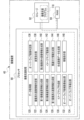
- the aircraft 10 includes a computer 12, a communication device 14, multiple propellers 16, multiple motors 18, a motor driver 20, and an input/output I/F 22.
- the computer 12 includes a processor 30, storage 32, and RAM34.
- Processor 30 , storage 32 , and RAM 34 are interconnected via bus 36 , and bus 36 is connected to input/output I/F 22 .
- the processor 30 has, for example, a CPU, and controls the aircraft 10 as a whole.
- the storage 32 is a nonvolatile storage device that stores various programs, various parameters, and the like. Examples of the storage 32 include HDDs and SSDs. Note that the HDD and SSD are merely examples, and flash memory, magnetoresistive memory, and/or ferroelectric memory may be used in place of or together with the HDD and/or SSD. .
- the RAM 34 is a memory that temporarily stores information, and is used by the processor 30 as a work memory. Examples of the RAM 34 include DRAM and/or SRAM.
- the communication device 14 is communicably connected to the imaging device 40 .
- the communication device 14 is wirelessly communicably connected to the imaging device 40 according to a predetermined wireless communication standard.
- the predefined wireless communication standard includes, for example, Bluetooth (registered trademark).
- wireless communication is exemplified here, the technology of the present disclosure is not limited to this, and wired communication may be applied instead of wireless communication.
- the communication device 14 is in charge of exchanging information with the imaging device 40 .
- the communication device 14 transmits information requested by the processor 30 to the imaging device 40 .
- the communication device 14 also receives information transmitted from the imaging device 40 and outputs the received information to the processor 30 via the bus 36 .
- Each propeller 16 is fixed to the rotating shaft of the motor 18.
- Each motor 18 rotates the propeller 16 .
- a plurality of motors 18 are connected to a motor driver 20 .
- Motor driver 20 is connected to processor 30 via input/output I/F 22 and bus 36 .
- Motor driver 20 individually controls multiple motors 18 according to instructions from processor 30 .
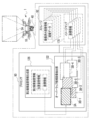
- the imaging device main body 42 includes a computer 52, a communication device 54, an image sensor 56, an image sensor driver 58, an imaging lens 60, a focus actuator 62, a zoom actuator 64, an aperture actuator 66, and a focus sensor 72. , a zoom sensor 74 , an aperture sensor 76 , a controller 78 , and an input/output I/F 80 .
- the computer 52 includes a processor 90 , storage 92 and RAM 94 .
- Processor 90 , storage 92 , and RAM 94 are interconnected via bus 96 , and bus 96 is connected to input/output I/F 80 .
- the computer 52 is an example of an “imaging support device” and a “computer” according to the technology of the present disclosure.
- the processor 90 is an example of a "processor" according to the technology of the present disclosure.
- the multiple hardware resources that implement the computer 12 shown in FIG.
- the multiple hardware resources that implement the computer 12 shown in FIG. it is the same as the specific example of the types of the processor 30, the storage 32, and the RAM 34), so a description thereof will be omitted.
- the types of the multiple hardware resources that implement the computer 52 are not necessarily the same as the types of the multiple hardware resources that implement the computer 12 shown in FIG. 2, and may be of different types. Needless to say.
- the processor 90 controls the entire imaging device 40 by cooperating with the storage 92 and the RAM 94 .
- the communication device 54 is communicably connected to the aircraft 10 .
- the communication device 54 is implemented by hardware resources similar to the communication device 14 (see FIG. 2) of the aircraft 10 .
- the communication device 54 is in charge of exchanging information with the aircraft 10 .
- communication device 54 transmits information to aircraft 10 in response to a request from processor 90 .
- Communication device 54 also receives information transmitted from aircraft 10 and outputs the received information to processor 90 via bus 96 .
- the sensor unit 44 includes an inertial sensor 98 , an inertial sensor driver 100 , a distance sensor 102 and a distance sensor driver 104 .
- Inertial sensor 98, inertial sensor driver 100, distance sensor 102, distance sensor driver 104, image sensor 56, image sensor driver 58, and controller 78 are connected to processor 90 via input/output I/F 80 and bus 96. .
- the inertial sensor 98 is connected to the inertial sensor driver 100.
- Inertial sensor driver 100 controls inertial sensor 98 according to instructions from processor 90 .
- the inertial sensor 98 detects the acceleration and angular velocity acting on the imaging device 40 under the control of the inertial sensor driver 100, and generates inertial data corresponding to the detected acceleration and angular velocity (for example, data indicating the acceleration itself and the angular velocity itself). data) to the processor 90 .
- the distance sensor 102 is connected to a distance sensor driver 104.
- Distance sensor driver 104 controls distance sensor 102 according to instructions from processor 90 .
- the distance sensor 102 measures, for example, the distance between the imaging target area 3A of the wall surface 2A (see FIG. 1) and the distance sensor 102, and outputs distance data corresponding to the measured distance. (for example, data indicating the distance itself) is output to the processor 90 .
- the image sensor 56 is connected with an image sensor driver 58 .
- Image sensor driver 58 controls image sensor 56 according to instructions from processor 90 .
- Image sensor 56 is, for example, a CMOS image sensor. Although a CMOS image sensor is exemplified as the image sensor 56 here, the technology of the present disclosure is not limited to this, and other image sensors may be used.
- the image sensor 56 captures an image of a subject (for example, the wall surface 2A of the target object 2) under the control of the image sensor driver 58, and outputs image data obtained by capturing the image to the processor 90.
- the imaging lens 60 is arranged on the subject side (object side) of the image sensor 56 .
- the imaging lens 60 captures subject light, which is reflected light from the subject, and forms an image of the captured subject light on the imaging surface of the image sensor 56 .
- the imaging lens 60 includes a plurality of optical elements (not shown) such as a focus lens, a zoom lens, and an aperture.
- the imaging lens 60 is connected to the computer 52 via the input/output I/F80.
- the plurality of optical elements included in the imaging lens 60 are connected to the input/output I/F 80 via a drive mechanism (not shown) having a power source.
- a plurality of optical elements included in imaging lens 60 operate under the control of computer 52 . In the imaging device 40, by operating a plurality of optical elements included in the imaging lens 60, adjustment of focus, optical zoom, shutter speed, etc. is realized.
- the storage 92 stores an imaging support program 118 .
- the imaging support program 118 is an example of a “program” according to the technology of the present disclosure.
- the processor 90 reads the imaging assistance program 118 from the storage 92 and executes the read imaging assistance program 118 on the RAM 94 .
- the processor 90 performs imaging support processing for synthesizing a plurality of images 162 (see FIG. 1) according to the imaging support program 118 executed on the RAM 94 .
- the imaging support processing is performed by the processor 90 according to the imaging support program 118, the data acquisition unit 120, the captured image information determination unit 122, the first imaging device information generation unit 124, the second imaging device information generation unit 126, the first captured image Information generation unit 128, image map creation unit 130, overlap candidate image extraction unit 132, overlap rate derivation unit 134, overlap image determination unit 136, change instruction unit 138, second captured image information generation unit 140, image map It is realized by operating as the update unit 142 , the association information generation unit 144 , the composite image data generation unit 146 , and the movement instruction unit 148 .
- the data acquisition unit 120 acquires inertial data input from the inertial sensor 98 to the processor 90 and distance data input from the distance sensor 102 to the processor 90 .
- the storage 92 stores captured image information.
- the captured image information includes image data and the like.
- the storage 92 may or may not store captured image information. Therefore, the imaged image information determination unit 122 determines whether or not imaged image information is stored in the storage 92 .
- the first imaging device information generation unit 124 uses the inertia data and the distance data acquired by the data acquisition unit 120 as Based on this, the first imaging device information is generated.
- the first imaging device information includes position and orientation information and coordinate information.
- the position and orientation information includes position information indicating the position of the imaging device 40 and orientation information indicating the orientation of the imaging device 40 .
- the position and orientation information included in the first imaging device information is reference information that serves as a reference for the position and orientation information included in the second imaging device information, which will be described later. That is, the position of the imaging device 40 indicated by the position information in the position and orientation information included in the first imaging device information is set as the reference position at the origin of the first three-dimensional coordinate system set for the imaging device 40. be done.
- the orientation of the imaging device 40 indicated by the orientation information of the position and orientation information included in the first imaging device information is represented as a reference orientation by angles with respect to each coordinate axis of the above-described first three-dimensional coordinate system.
- the position and orientation information also includes distance information indicating the distance between the imaging target region 3A and the imaging device 40, and relative orientation information indicating the orientation of the imaging device 40 with respect to the imaging target region 3A.
- Distance information indicating the distance between the imaging target area 3A and the imaging device 40 is information corresponding to the distance data output from the distance sensor 102 .
- the attitude of the imaging device 40 with respect to the imaging target region 3A is represented by angles with respect to each coordinate axis of the second three-dimensional coordinate system set on the wall surface 2A (see FIG. 1) of the object 2.
- the coordinate information is information about the position of the imaging target area 3A.
- the coordinate information is information indicating the position of the imaging target area 3A, that is, information indicating the coordinates of the four vertices of the imaging target area 3A.
- the coordinate information is generated based on the position and orientation information, for example. That is, the coordinate information is based on position information indicating the position of the imaging device 40, distance information indicating the distance between the imaging target region 3A and the imaging device 40, posture information indicating the posture of the imaging device 40 with respect to the imaging target region 3A, and the like. generated by
- the imaging device 40 when generating the coordinate information, other position information about the position of the imaging device 40 is used instead of the position information indicating the position of the imaging device 40 or in addition to the position information indicating the position of the imaging device 40. may Further, when generating the coordinate information, instead of the distance information indicating the distance between the imaging target area 3A and the imaging device 40, or in addition to the distance information indicating the distance between the imaging target region 3A and the imaging device 40, the imaging Other distance information regarding the distance between the target area 3A and the imaging device 40 may be used.
- the imaging target region instead of the orientation information indicating the orientation of the imaging device 40 with respect to the imaging target region 3A, or in addition to the orientation information indicating the orientation of the imaging device 40 with respect to the imaging target region 3A, the imaging target region Other orientation information regarding the orientation of imaging device 40 relative to 3A may also be used.
- One of the four vertices of the imaging target area 3A indicated by the coordinate information included in the first imaging device information is set as the origin of the two-dimensional coordinate system set on the wall surface 2A of the object 2. be.
- the coordinates of the remaining three vertices of the four vertices of the imaging target area 3A indicated by the coordinate information included in the first imaging device information are relative coordinates with respect to the origin of the two-dimensional coordinate system described above.
- the second imaging device information generation unit 126 When the captured image information determination unit 122 determines that the captured image information is stored in the storage 92, the second imaging device information generation unit 126 combines the inertia data and the distance data acquired by the data acquisition unit 120. , and the first imaging device information generated by the first imaging device information generation unit 124, the second imaging device information is generated.
- the second imaging device information also includes position and orientation information and coordinate information, like the first imaging device information.
- the position and orientation information included in the second imaging device information is relative information with respect to the position and orientation information included in the first imaging device information. That is, the position of the imaging device 40 indicated by the position information included in the position and orientation information included in the second imaging device information is the position of the imaging device 40 indicated by the position information included in the position and orientation information included in the first imaging device information. is the position relative to the position of Also, the orientation of the imaging device 40 indicated by the orientation information included in the position and orientation information included in the second imaging device information is the orientation of the imaging device 40 indicated by the orientation information included in the position and orientation information included in the first imaging device information. It is the relative posture to the posture of
- the position and orientation information included in the second imaging device information also includes distance information indicating the distance between the imaging target region 3A and the imaging device 40, and the distance information indicating the distance between the imaging target region 3A and the imaging device 40, and the position and orientation information of the imaging device 40 with respect to the imaging target region 3A, similarly to the first imaging device information. and relative attitude information indicating the attitude.
- the coordinates of the four vertices of the imaging target area 3A indicated by the coordinate information included in the second imaging device information are relative coordinates with respect to the origin of the two-dimensional coordinate system set on the wall surface 2A of the object 2.
- the position of the imaging device 40 is, for example, a position based on the center of the image sensor 56 (see FIG. 3).
- the position of the imaging device 40 is calculated based on the acceleration specified from the inertia data, taking into consideration the positional deviation between the imaging device main body 42 and the sensor unit 44 .
- the attitude of the imaging device 40 is calculated based on the angular velocity indicated by the inertia data.
- the distance between the imaging target area 3A and the imaging device 40 is the distance based on the center of the image sensor 56, for example.
- the distance between the imaging target region 3A and the imaging device 40 is the distance specified from the distance data (that is, the distance between the imaging target region 3A and the distance sensor 102) in consideration of the positional deviation between the imaging device main body 42 and the sensor unit 44.
- the position information included in the position and orientation information is an example of "fourth position information” according to the technology of the present disclosure.
- the distance information included in the position and orientation information is an example of “distance information” according to the technology of the present disclosure.
- the relative orientation information included in the position and orientation information is an example of "attitude information” according to the technique of the present disclosure.
- the coordinate information included in the second imaging device information is an example of "second position information” and "third position information” according to the technology of the present disclosure.
- the first generated captured image information is stored in the storage 92, and an image map 170 including the coordinate information included in the first generated first imaging device information is stored in the storage 92. A state of being stored is shown.
- the first captured image information generation unit 128 outputs an image capturing instruction signal to the image sensor 56 to cause the image sensor 56 to capture an image of the target area 3A. Then, the first captured image information generation unit 128 generates the image data input from the image sensor 56 to the processor 90 and the position and orientation information included in the first imaging device information generated by the first imaging device information generation unit 124 . Based on and, imaged image information is generated.
- the imaged image information includes image data, feature point information, incidental information, and position and orientation information.
- the image data is image data representing an image obtained by imaging the imaging target region 3A by the image sensor 56 (hereinafter referred to as a “captured image”).
- the feature point information is information indicating coordinates of feature points included in the imaging target region 3A imaged by the image sensor 56 .
- the coordinates of the feature points are derived, for example, by subjecting the image data to image processing (for example, high-frequency component extraction processing, etc.).
- the coordinates of the feature point are, for example, coordinates based on any one of the four vertices of the imaging target region 3A.
- Supplementary information is, for example, information indicating focal length and/or resolution.
- the focal length is derived based on the position of the zoom lens within the imaging lens 60 (see FIG. 3).
- Resolution is derived based on the position of the focus lens within the imaging lens 60 (see FIG. 3).
- the position and orientation information is information generated by the first imaging device information generation unit 124 as described above.
- the captured image information generated by the first captured image information generation unit 128 is stored in the storage 92 .
- the image map creating unit 130 creates an image map 170 including the coordinate information included in the first imaging device information generated by the first imaging device information generating unit 124 .
- the image map 170 is formed by a plurality of pieces of coordinate information (see FIG. 7) when the imaging support processing proceeds.
- the image map 170 uses a plurality of pieces of coordinate information to form the coordinates of the four vertexes of the plurality of photographed regions 3B (see FIG. 1) corresponding to each piece of coordinate information, and thus the plurality of photographed images corresponding to each photographed region 3B. is an information group indicating the position of each.
- the image map 170 is an example of an "image map" according to the technology of the present disclosure.
- the image map 170 created by the image map creating unit 130 is stored in the storage 92.
- the coordinate information included in the image map 170 is stored in the storage 92 in association with the imaged image information generated by the first imaged image information generation unit 128 .
- the image map 170 may be information indicating relative positional relationships between a plurality of already-captured images.
- FIG. 7 shows a state in which a plurality of already-captured image information are stored in the storage 92 and the image map 170 includes a plurality of pieces of coordinate information as a result of progress of the imaging support processing. .
- the number of pieces of captured image information stored in the storage 92 and the number of pieces of coordinate information included in the image map 170 are both five.
- the captured image information stored first in the storage 92 among the plurality of captured image information is the captured image information generated by the above-described first captured image information generation unit 128 (see FIG. 6).
- the captured image information stored in the storage 92 after the second among the plurality of captured image information is the captured image generated by the second captured image information generation unit 140 (see FIG. 10) described later. Information.
- the coordinate information included in the image map 170 first among the plurality of pieces of coordinate information is the coordinate information included in the image map 170 by the above-described image map creation unit 130 (see FIG. 6). Further, the coordinate information included in the image map 170 after the second among the plurality of pieces of coordinate information is the coordinate information included in the image map 170 by the image map updating unit 142 (see FIG. 10) described later. Each piece of captured image information is associated with coordinate information. Image data included in each of the plurality of captured image information is image data representing a captured image.
- the overlap candidate image extracting unit 132 extracts a plurality of images based on a plurality of pieces of coordinate information included in the image map 170 and coordinate information included in the second image capturing device information generated by the second image capturing device information generating unit 126.
- a captured image that is a candidate for overlapping with the imaging target region 3A (hereinafter referred to as an “overlap candidate image”) is extracted from the captured images.
- the overlap candidate image extracting unit 132 extracts the coordinates of the four vertexes of the imaging target region 3A indicated by the coordinate information included in the second imaging device information, and the coordinates indicated by each coordinate information included in the image map 170.
- the coordinates of the four vertices of each captured area 3B are compared, and based on the comparison result, the captured area 3B overlapping the imaging target area 3A is extracted from the plurality of captured areas 3B.
- Each imaged area 3B corresponds to the imaged image indicated by the image data included in the imaged image information.
- the branch numbers 1 to 5 attached to the reference numerals of the imaged area 3B in FIG. 7 indicate the order in which the imaged area 3B is imaged.
- the first imaged area 3B (hereinafter also referred to as “imaged area 3B-1”) and the fifth imaged area 3B (hereinafter referred to as “imaged area 3B-5”) overlaps the imaging target region 3A, and the captured image corresponding to the first captured region 3B-1 and the fifth captured region
- imaged area 3B-5 overlaps the imaging target region 3A, and the captured image corresponding to the first captured region 3B-1 and the fifth captured region
- the captured image corresponding to 3B-5 is extracted as an overlap candidate image.
- a captured image is an example of a "captured image” according to the technology of the present disclosure.
- the image map 170 is an example of "first location information” according to the technology of the present disclosure.
- the overlap candidate image is an example of the "overlap candidate image” according to the technology of the present disclosure.
- the overlap rate derivation unit 134 derives the overlap rate between the imaging target region 3A and the overlap candidate image extracted by the overlap candidate image extraction unit 132. Specifically, the overlap rate derivation unit 134 calculates the overlap rate between the imaging target area 3A and the imaged area 3B corresponding to the overlap candidate image.
- imaging is performed based on the coordinates of the four vertices of the imaging target region 3A and the coordinates of the four vertices of the imaging completed region 3B.
- An overlap ratio between the target area 3A and the imaged area 3B is calculated.
- a live view image corresponding to the imaging target region 3A is acquired, and the result of comparing feature points between the live view image and the captured image is the overlap ratio between the imaging target region 3A and the captured region 3B.
- the overlap ratio between the imaging target area 3A and the first imaged area 3B-1 is calculated. Also, in the example shown in FIG. 8, the overlap ratio between the imaging target area 3A and the fifth imaged area 3B-5 is calculated.
- the overlap image determination unit 136 selects, among the overlap candidate images for which the overlap ratio is derived by the overlap ratio derivation unit 134, captured images having an overlap ratio equal to or higher than a predetermined overlap ratio (hereinafter referred to as “overlap It is determined whether or not there is a wrap image.
- the overlap image determination unit 136 determines that the overlap ratio of the imaged area 3B calculated by the overlap ratio derivation unit 134 with respect to the imaging target area 3A is equal to or greater than the predetermined overlap ratio. In this case, it is determined that the captured image corresponding to the captured area 3B is the overlap image. Further, if the overlap ratio of the imaged area 3B calculated by the overlap ratio derivation unit 134 with the imaging target area 3A is less than the default overlap ratio, the overlap image determination unit 136 determines that the overlap ratio is less than the predetermined overlap ratio. It is determined that the captured image corresponding to the completed area 3B is not an overlap image.
- the change instruction unit 138 generates a change instruction when the overlap image determination unit 136 determines that there is no overlap image.
- the change instruction is, for example, an instruction to change the position and/or orientation of the imaging device 40 in a direction and/or orientation in which the imaging target area 3A approaches the imaged area 3B corresponding to the overlap candidate image.
- the change instructing unit 138 changes the captured image corresponding to the image capturing target region 3A and the overlap candidate image based on the coordinate information corresponding to the image capturing target region 3A and the coordinate information corresponding to the overlap candidate image. Identify the positional relationship with the area 3B. In addition, the change instructing unit 138 determines the specified positional relationship, the position and orientation information included in the second imaging device information generated by the second imaging device information generation unit 126 corresponding to the imaging target region 3A, and the overlap candidate. The change instruction is generated based on the position and orientation information included in the captured image information stored in the storage 92 corresponding to the image. Then, the change instruction unit 138 outputs a change instruction signal indicating the generated change instruction to the aircraft 10, for example.
- the change instruction signal is an example of a "change instruction signal" according to the technology of the present disclosure.
- the flying object 10 changes the position and/or attitude of the flying object 10 by adjusting the number of rotations of the propellers 16 based on the change instruction signal input from the imaging device 40 .
- the position and/or orientation of the imaging device 40 is changed, which in turn changes the position of the imaging target region 3A by the imaging device 40 (for example, the position of the imaging target region 3A at 4 coordinates of one vertex) are changed.
- the change instruction unit 138 may output a change instruction signal to a transmitter (not shown) that transmits a flight instruction signal to the aircraft 10 and/or a base station (not shown).
- the change instruction indicated by the change instruction signal may be displayed on a display (not shown) provided in the transmitter. Further, the display may display a frame indicating the imaging target region 3A, a frame indicating the captured region 3B corresponding to the overlap candidate image, and the overlap ratio derived by the overlap ratio derivation unit 134. good.
- the transmitter may then transmit a flight instruction signal to the aircraft 10 based on the change instruction signal. Further, when the change instruction signal is output to the base station, the base station may transmit the flight instruction signal to the aircraft 10 based on the change instruction signal.
- the change instruction may be a change permission instruction that permits the change.
- the change permission instruction indicated by the change instruction signal may be displayed on a display (not shown) provided in the transmitter. Further, the display may display a frame indicating the imaging target region 3A, a frame indicating the captured region 3B corresponding to the overlap candidate image, and the overlap ratio derived by the overlap ratio derivation unit 134. good. Then, the transmitter may transmit a flight instruction signal to the aircraft 10 based on a command given to the transmitter by the user based on the change permission instruction displayed on the display.
- the second captured image information generation unit 140 outputs an image capturing instruction signal to the image sensor 56 when the overlap image determination unit 136 determines that an overlap image exists. This causes the image sensor 56 to pick up an image of the imaging target area 3A. Then, the second captured image information generation unit 140 generates the image data input from the image sensor 56 to the processor 90 and the position and orientation information included in the second imaging device information generated by the second imaging device information generation unit 126. Based on and, imaged image information is generated.
- the imaged image information generated by the second imaged image information generation unit 140 is the same as the imaged image information generated by the first imaged image information generation unit 128, and includes image data, feature point information, and incidental information. , and pose information.
- the captured image information generated by the second captured image information generation unit 140 is stored in the storage 92 .
- the imaging instruction signal output to the image sensor 56 by the second captured image information generation unit 140 is an example of the "first signal” and the "imaging instruction signal" according to the technology of the present disclosure.
- the imaging instruction signal may be output to a transmitter (not shown) and/or a base station (not shown) that transmits the flight instruction signal to the aircraft 10 . Further, when an imaging instruction signal is output to the transmitter, the imaging instruction indicated by the imaging instruction signal may be displayed on a display (not shown) provided in the transmitter. Then, the transmitter may transmit the imaging instruction signal to the imaging device 40 . Further, when the imaging instruction signal is output to the base station, the base station may transmit the imaging instruction signal to the imaging device 40 based on the imaging instruction signal.
- the imaging instruction may be an imaging permission instruction that permits imaging.
- the imaging instruction signal When the imaging instruction signal is output to the transmitter, the imaging permission instruction indicated by the imaging instruction signal may be displayed on a display (not shown) provided in the transmitter. Then, the transmitter may transmit the imaging instruction signal to the imaging device 40 based on the command given to the transmitter by the user based on the imaging permission instruction displayed on the display.
- the image map updating unit 142 acquires the coordinate information included in the second imaging device information generated by the second imaging device information generation unit 126. Then, the image map update unit 142 updates the image map 170 by including the acquired coordinate information in the image map 170 .
- the coordinate information included in the image map 170 is stored in the storage 92 in association with the imaged image information generated by the second imaged image information generating section 140 .
- association information generation unit 144 determines that the image data included in the captured image information generated by the captured image information generated by the second captured image information generation unit 140 is indicated by the captured image that is the overlap image.
- Association information is generated that is information that associates the two captured images with a captured image (that is, a new captured image).
- the association information generation unit 144 stores in the storage 92 corresponding to the feature point information included in the captured image information generated by the second captured image information generation unit 140 and the overlapping image. Feature point information included in captured image information is acquired. Then, the association information generation unit 144 extracts the feature points commonly included in the two captured images based on the acquired two pieces of feature point information, and generates association information including information indicating the extracted feature points. do.
- the association information generated by the association information generation unit 144 is stored in the storage 92 in association with captured image information corresponding to each of the two captured images.
- FIG. 11 shows a table 150 that schematically shows the relationship between a plurality of pieces of association information stored in the storage 92 and a plurality of pieces of captured image information stored in the storage 92 .
- the "image number" shown in the table 150 indicates the order in which the multiple captured images were obtained.
- “ ⁇ (circle symbol)” shown in the table 150 indicates that there is association information corresponding to the captured image
- “blank” in the table 150 indicates association information corresponding to the captured image. does not exist.
- the table 150 indicates that there is association information that associates the first captured image and the sixth captured image.
- the table 150 also indicates that there is association information that associates the fifth captured image and the sixth captured image.
- a captured image that is an overlap image is an example of a "first captured image” according to the technology of the present disclosure.
- a captured image indicated by image data included in captured image information generated by the second captured image information generation unit 140 is an example of a “second captured image”.
- the association information is an example of "association information" according to the technology of the present disclosure.
- Information indicating feature points extracted by the association information generation unit 144 is an example of "feature point information” relating to the technology of the present disclosure.
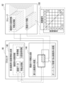
- the composite image data generation unit 146 acquires a plurality of imaged image information and a plurality of association information from the storage 92 . Then, the composite image data generation unit 146 generates composite image data representing the composite image 160 based on the image data included in the multiple captured image information and the multiple pieces of association information.
- the composite image 160 is the captured images corresponding to the association information (that is, the captured images partially overlapping each other) for the plurality of captured images indicated by the image data included in the plurality of captured image information.
- is an image obtained by synthesizing Synthetic image 160 is, for example, a panoramic image.
- Synthetic image 160 is an example of a “synthetic image” according to the technology of the present disclosure.
- FIG. 12 shows how a composite image 160 is generated from a plurality of images 162 .
- Each image 162 is a captured image indicated by image data included in the captured image information.
- the movement instruction unit 148 outputs a movement instruction signal indicating a movement instruction to the flying object 10 .
- a new area of the wall surface 2A (see FIG. 1) is set as the imaging target area 3A by moving the flying object 10 based on the movement instruction signal.
- the movement instructing unit 148 extracts an area of the wall surface 2A that has not been imaged based on a plurality of pieces of coordinate information included in the image map 170, and moves the imaging device 40 to the position where the extracted area is the imaging target area 3A. (i.e., a position specifying instruction specifying a position to move) may be generated.
- a movement instruction signal indicating a position designation instruction is input to the flying object 10
- the flying object 10 flies according to the movement instruction signal, thereby moving the imaging device 40 to the position designated by the position designation instruction. good.
- the movement instruction unit 148 may output a movement instruction signal to a transmitter (not shown) and/or a base station (not shown) that transmits a flight instruction signal to the aircraft 10 .
- a transmitter not shown
- a base station not shown
- the movement instruction indicated by the movement instruction signal may be displayed on a display (not shown) provided in the transmitter.
- the transmitter may then transmit a flight instruction signal to the aircraft 10 .
- the base station may transmit the flight instruction signal to the aircraft 10 based on the movement instruction signal.
- the movement instruction may be a movement permission instruction that permits movement.
- a movement instruction signal When a movement instruction signal is output to the transmitter, a movement permission instruction indicated by the movement instruction signal may be displayed on a display (not shown) provided in the transmitter.
- the display may also display a composite image 160 that includes multiple images 162 .
- the transmitter may transmit a flight instruction signal to the aircraft 10 based on a command given to the transmitter by the user based on the movement permission instruction displayed on the display.
- FIG. 13 shows an example of the flow of imaging support processing according to this embodiment.
- step ST10 the data acquisition unit 120 acquires inertial data input from the inertial sensor 98 to the processor 90 and distance data input from the distance sensor 102 to the processor 90. (see Figure 5). After the process of step ST10 is executed, the imaging support process proceeds to step ST12.
- step ST12 the captured image information determination unit 122 determines whether captured image information related to the captured image is stored in the storage 92 (see FIG. 5). In step ST12, if the captured image information is not stored in the storage 92, the determination is negative, and the imaging support process proceeds to step ST14. In step ST12, if the captured image information is stored in the storage 92, the determination is affirmative, and the imaging support process proceeds to step ST20.
- step ST14 the first imaging device information generation unit 124 generates first imaging device information including position/orientation information and coordinate information regarding the imaging device 40 based on the inertia data and distance data acquired in step ST10 ( See Figure 5). After the process of step ST14 is executed, the imaging support process proceeds to step ST16.
- step ST16 the first captured image information generation unit 128 causes the image sensor 56 mounted on the imaging device 40 to capture an image of the imaging target region 3A. Then, the first captured image information generation unit 128 performs image capturing based on the image data input from the image sensor 56 to the processor 90 and the position and orientation information included in the first image capturing device information generated in step ST14. Captured image information about the captured image is generated (see FIG. 6). The captured image information is stored in the storage 92 . After the process of step ST16 is executed, the imaging support process proceeds to step ST18.
- the image map creating section 130 creates an image map 170 including the coordinate information included in the first imaging device information generated at step ST14 (see FIG. 6).
- the coordinate information included in the image map 170 is stored in the storage 92 in association with the imaged image information generated by the first imaged image information generation unit 128 .
- the imaging support process proceeds to step ST10.
- step ST20 the second imaging device information generation unit 126 generates position and orientation information about the imaging device 40 based on the inertia data and distance data acquired in step ST10 and the first imaging device information generated in step ST14. and second imaging device information including coordinate information (see FIG. 5).
- the imaging support process proceeds to step ST22.
- step ST22 the overlap candidate image extraction unit 132 extracts images of objects to be imaged by the imaging device 40 based on the coordinate information included in the image map 170 and the coordinate information included in the second imaging device information generated in step ST20.
- An overlap candidate image that is a candidate for overlapping with the area 3A is extracted (see FIG. 7).
- step ST22 of the first time a captured image corresponding to one captured image information stored in the storage 92 is extracted as an overlap candidate image.
- step ST ⁇ b>22 for the second and subsequent times overlap candidate images are extracted from a plurality of captured images corresponding to each of the plurality of captured image information stored in the storage 92 .
- step ST24 the overlap rate derivation unit 134 derives the overlap rate between the imaging target area 3A by the imaging device 40 and the overlap candidate image extracted at step ST22 (see FIG. 8). After the process of step ST24 is executed, the imaging support process proceeds to step ST26.
- step ST26 the overlap image determination unit 136 determines whether or not there is an overlap image whose overlap ratio is equal to or higher than the default overlap ratio among the overlap candidate images for which the overlap ratio has been derived in step ST24. (See FIG. 9). In step ST26, if there is no overlapping image, the determination is negative, and the imaging support process proceeds to step ST28. In step ST26, if there is an overlapping image, the determination is affirmative, and the imaging support process proceeds to step ST30.
- step ST28 the change instructing unit 138 changes the imaging device based on the coordinate information included in the second imaging device information generated in step ST20 and the coordinate information corresponding to the overlap candidate image extracted in step ST22.
- a change instruction is generated, which is an instruction to change the position and/or orientation of 40 (see FIG. 9).
- the change instruction unit 138 outputs a change instruction signal indicating the generated change instruction to the aircraft 10, for example.
- the position and/or orientation of the flying object 10 is changed, thereby changing the position and/or orientation of the imaging device 40, which in turn changes the position of the imaging target region 3A by the imaging device 40 (for example, the imaging target region 3A) are changed.
- the imaging support process proceeds to step ST10.
- step ST30 the second imaged image information generating section 140 causes the image sensor 56 to image the imaging target region 3A (see FIG. 10). Then, the second imaged image information generation unit 140 performs imaging based on the image data input from the image sensor 56 to the processor 90 and the position and orientation information included in the second imaging device information generated in step ST20. Generate finished image information. The captured image information is stored in the storage 92 . After the process of step ST30 is executed, the imaging support process proceeds to step ST32.
- step ST32 the image map updating unit 142 acquires the coordinate information included in the second imaging device information generated in step ST20, and updates the image map 170 by including the acquired coordinate information in the image map 170. (See FIG. 10).
- the coordinate information included in the image map 170 is stored in the storage 92 in association with the imaged image information generated by the second imaged image information generating section 140 .
- the imaging support process proceeds to step ST34.
- step ST34 the association information generation unit 144 compares the captured image determined to be the overlapping image in step ST26 with the captured image indicated by the image data included in the captured image information generated in step ST30.
- Association information which is information for associating two captured images, is generated (see FIG. 11).
- the association information is stored in the storage 92 in association with captured image information corresponding to each of the two captured images.
- the composite image data generation unit 146 acquires a plurality of imaged image information and a plurality of association information from the storage 92 (see FIG. 12). Then, the composite image data generation unit 146 generates composite image data based on the image data included in the multiple captured image information and the multiple pieces of association information. As a result, a composite image 160 represented by the composite image data is obtained.
- the imaging support process proceeds to step ST38.
- the movement instruction unit 148 outputs a movement instruction signal indicating a movement instruction to the aircraft 10 (see FIG. 12).
- a new area of the wall surface 2A (see FIG. 1) is set as the imaging target area 3A as the flying object 10 moves.
- the processor 90 determines whether or not the condition for ending the imaging support process is satisfied.
- conditions for ending the imaging support process include a condition that the user ends the imaging support process, a condition that the number of captured images reaches the number specified by the user, and the like.
- the determination is negative, and the imaging support process proceeds to step ST10.
- the determination is affirmative, and the imaging support processing ends.
- the imaging support method described as the operation of the flight imaging device 1 described above is an example of the "imaging support method" according to the technology of the present disclosure.
- the processor 90 performs the Overlap candidate images, which are candidates for overlapping with the imaging target area 3A by the imaging device 40, are extracted from the plurality of already-captured images (see FIG. 7). Then, the overlap ratio between the imaging target region 3A and the overlap candidate image is derived (see FIG. 8). An imaging instruction signal is output (see FIG. 10). Therefore, for example, compared to the case where the imaging target region 3A whose overlap rate with the captured image is equal to or higher than the predetermined overlap rate is determined in the order in which the multiple captured images are obtained, It is possible to determine with a high degree of freedom the imaging target region 3A whose overlap rate is equal to or higher than the predetermined overlap rate.
- the processor 90 extracts overlap candidate images, which are candidates for overlapping with the imaging target region 3A by the imaging device 40, from a plurality of captured images (see FIG. 7), and An overlap ratio with the overlap candidate image is derived (see FIG. 8). Therefore, for example, the load on the processor 90 can be reduced compared to the case where the overlap ratio between the imaging target region 3A and the multiple captured images is derived.
- the storage 92 also stores an image map 170 indicating the position of each of the multiple captured images (see FIG. 7). Therefore, based on the image map 170, it is possible to extract overlap candidate images, which are candidates for overlapping with the imaging target area 3A by the imaging device 40, from a plurality of already-captured images.
- the processor 90 when the overlap ratio is equal to or higher than the predetermined overlap ratio, the processor 90 outputs an imaging instruction signal instructing the image sensor 56 of the imaging device 40 to image the imaging target region 3A (see FIG. 10). ). Therefore, when the overlap rate is equal to or higher than the predetermined overlap rate, a new captured image can be obtained by capturing an image of the imaging target region 3A with the image sensor 56 .
- the processor 90 stores captured image information (that is, the second captured image) corresponding to the new captured image.
- the image map 170 is updated based on the coordinate information included in the captured image information generated by the image information generation unit 140 (see FIG. 10). Therefore, when the image map 170 is updated, based on the updated image map 170, it is possible to extract overlap candidate images that are candidates for overlapping with the imaging target region 3A by the imaging device 40.
- FIG. 10 illustrates the image map 170 based on the updated image map 170.
- the processor 90 also captures a captured image that is an overlap candidate image having an overlap rate equal to or higher than a predetermined overlap rate, and a captured image obtained by capturing an image with the image sensor 56 in accordance with the imaging instruction signal. to generate association information that associates the two captured images (see FIG. 11). Therefore, two captured images can be synthesized based on the association information.
- the association information also includes feature point information regarding feature points commonly included in two captured images (see FIG. 11). Therefore, two captured images can be synthesized based on the common feature points indicated by the feature point information.
- the processor 90 generates a synthesized image 160 by synthesizing the two captured images based on the association information (see FIG. 12). Therefore, for example, it is possible to generate a composite image 160 with higher precision than when two captured images are composited without based on the association information.
- the processor 90 extracts overlap candidate images based on the image map 170 regarding the position of each of the multiple captured images and the coordinate information regarding the position of the imaging target area 3A (see FIG. 7). Therefore, overlap candidate images can be extracted by comparing the coordinates of the four vertices of the captured area 3B corresponding to each captured image with the coordinates of the four vertices of the captured area 3A.
- the coordinate information regarding the position of the imaging target area 3A includes position information indicating the position of the imaging device 40, distance information indicating the distance between the imaging target region 3A and the imaging device 40, and coordinate information indicating the position of the imaging device 40 with respect to the imaging target region 3A.
- This is information generated based on posture information indicating a posture. Therefore, it is possible to obtain the position of the imaging device 40, the distance between the imaging target region 3A and the imaging device 40, and the position of the imaging target region 3A corresponding to the attitude of the imaging device 40 with respect to the imaging target region 3A.
- the processor 90 outputs a change instruction signal indicating an instruction to change the position and/or attitude of the imaging device 40 to the aircraft 10 (see FIG. 9). reference). Therefore, the position and/or attitude of the flying object 10 is changed based on the change instruction signal, and the position and/or attitude of the imaging device 40 is changed, so that the position ( For example, the coordinates of the four vertices of the imaging target area 3A) can be changed.
- the processor 90 generates a change instruction signal based on the image map 170 regarding the position of each of the multiple captured images and the coordinate information regarding the position of the imaging target area 3A (see FIG. 9). Therefore, the position and/or orientation of the imaging device 40 can be changed based on the relative positional relationship between the position of each of the multiple captured images and the position of the imaging target region 3A.
- the processor 90 of the imaging device 40 generates synthetic image data representing the synthetic image 160 based on image data included in the plurality of captured image information stored in the storage 92 (see FIG. 12). reference).
- a plurality of image data is input from the processor 90 of the imaging device 40 to the processor 210 of the image processing device 200 communicably connected to the imaging device 40 by wired connection or wireless connection.
- the processor 210 of the image processing device 200 may generate the composite image data based on the plurality of input image data.
- the processor 210 is an example of a “synthesis processor” according to the technology of the present disclosure.
- the processor 90 and the processor 210 are examples of the "processor" according to the technology of the present disclosure.
- the processor 90 of the imaging device 40 does not need to generate synthetic image data, so the load on the processor 90 is reduced compared to the case where the processor 90 of the imaging device 40 generates synthetic image data. can do.
- the coordinate information that is the information regarding the position of the imaging target area 3A is used (see FIG. 7).
- information regarding the position of the imaging device 40 may be used.
- the image map 170 including coordinate information is used as the information regarding the position of each of a plurality of captured images (see FIG. 7).
- information in a system different from the image map 170 may be used.
- the multiple captured images are acquired by the imaging device 40, but the multiple captured images may be acquired by an imaging device other than the imaging device 40. Then, an overlap candidate image, which is a candidate for overlapping with the imaging target area of the imaging device 40, may be extracted from a plurality of captured images acquired by other imaging devices.
- processor 90 is illustrated in each of the above embodiments, at least one other CPU, at least one GPU, and/or at least one TPU may be used in place of or together with the processor 90 can be
- the imaging support program 118 may be stored in a portable non-temporary computer-readable storage medium such as an SSD or USB memory (hereinafter simply referred to as "non-temporary storage medium").
- the imaging assistance program 118 stored in the non-temporary storage medium is installed in the computer 52 of the imaging device 40, and the processor 90 executes processing according to the imaging assistance program 118.
- the image capturing support program 118 is stored in a storage device such as another computer or server device connected to the image capturing apparatus 40 via a network, and the image capturing support program 118 is downloaded in response to a request from the image capturing apparatus 40. It may be installed on computer 52 .
- imaging support program 118 it is not necessary to store all of the imaging support program 118 in a storage device such as another computer or server device connected to the imaging device 40, or in the storage 92, and a part of the imaging support program 118 may be stored. You can leave it.
- the computer 52 is built into the imaging device 40, the technology of the present disclosure is not limited to this, and the computer 52 may be provided outside the imaging device 40, for example.
- the computer 52 including the processor 90, the storage 92, and the RAM 94 is illustrated in each of the above-described embodiments, the technology of the present disclosure is not limited to this, and instead of the computer 52, an ASIC, FPGA, and/or Or you may apply the device containing PLD. Also, instead of the computer 52, a combination of hardware configuration and software configuration may be used.
- processors can be used as hardware resources for executing the various processes described in each of the above embodiments.
- processors include CPUs, which are general-purpose processors that function as hardware resources that execute various processes by executing software, that is, programs.
- processors include, for example, dedicated electronic circuits such as FPGAs, PLDs, and ASICs, which are processors having circuit configurations specially designed to execute specific processing.
- a memory is built in or connected to each processor, and each processor uses the memory to perform various processes.
- Hardware resources that perform various processes may be configured with one of these various processors, or a combination of two or more processors of the same or different types (for example, a combination of multiple FPGAs or CPUs). and FPGA). Also, the hardware resource for executing various processes may be one processor.
- one processor is configured by combining one or more CPUs and software, and this processor functions as a hardware resource that executes various processes.
- this processor functions as a hardware resource that executes various processes.
- SoC SoC, etc.
- a and/or B is synonymous with “at least one of A and B.” That is, “A and/or B” means that only A, only B, or a combination of A and B may be used. Also, in this specification, when three or more matters are expressed by connecting with “and/or”, the same idea as “A and/or B" is applied.
Abstract
This image capture supporting device comprises a processor that: extracts, on the basis of first position information related to the position of each of a plurality of captured images and second position information related to the position of an image capturing device, an overlapping candidate image, which is a candidate to be caused to overlap an image capture target area of the image capturing device, from the plurality of captured images; derives an overlapping rate between the image capture target area and the overlapping candidate image; and outputs a first signal to the image capturing device when the overlapping rate is equal to or greater than a predetermined overlapping rate.
Description
本開示の技術は、撮像支援装置、撮像支援方法、及びプログラムに関する。
The technology of the present disclosure relates to an imaging support device, an imaging support method, and a program.
特開2010-045587号公報には、画像を撮影する画像撮影部と、少なくとも画像を表示する画面を備えた画像表示部と、上記画像撮影部による画像撮影時の装置振れを検知する振れ検知部と、上記画像撮影部にて撮影された画像の情報を記録する画像記録部と、上記画像撮影部で直前に撮影されて上記画像記録部に記録された第一画像の撮影範囲と、上記第一画像の次に上記画像撮影部にて撮影される第二画像の撮影範囲との間の、少なくとも相対的な位置関係を表す相対関係度パラメータを求める相対関係演算部と、上記相対関係演算部が求めた上記相対関係度パラメータから上記撮影範囲間の相対的な位置関係を明示するための画像を生成し、当該画像を上記第二画像と共に上記画像表示部の画面上に表示させる表示制御部と、上記第一画像の撮影範囲と上記第二画像の撮影範囲との間の重なり具合を表す重複度パラメータを求める重複演算部と、上記重複演算部が求めた上記重複度パラメータに応じて撮影者へ所定の通知を行う通知部と、上記重複演算部が求めた上記重複度パラメータが所定の閾値範囲内となり、上記振れ検知部の検知出力から上記画像撮影部における画像撮影時に装置振れが略々無いと判断できる時に、上記画像撮影部に画像を撮影させる撮影制御部と、を有するカメラ装置が開示されている。
Japanese Patent Application Laid-Open No. 2010-045587 discloses an image capturing unit for capturing an image, an image display unit having at least a screen for displaying an image, and a shake detection unit for detecting device shake during image capturing by the image capturing unit. an image recording unit for recording information of an image captured by the image capturing unit; a capturing range of a first image captured immediately before by the image capturing unit and recorded in the image recording unit; a relative relationship calculation unit that obtains a degree of relative relationship parameter that represents at least a relative positional relationship between one image and a shooting range of a second image that is shot by the image shooting unit after the first image; a display control unit for generating an image for clarifying the relative positional relationship between the photographing ranges from the relative relationship parameter obtained by and displaying the image together with the second image on the screen of the image display unit and an overlap calculation unit that obtains a degree of overlap parameter representing a degree of overlap between the photographing range of the first image and the photographing range of the second image; The notifying unit that gives a predetermined notification to the user and the redundancy parameter obtained by the overlap calculating unit are within a predetermined threshold range, and from the detection output of the shake detecting unit, the apparatus shake during image capturing by the image capturing unit is substantially A camera device is disclosed that has a photographing control section that causes the image photographing section to photograph an image when it can be determined that there is no such thing.
特開2020-113843号公報には、対象物体の3次元形状モデルを復元するために用いる多視点画像の撮像を支援する画像撮像支援装置であり、対象物体を直前に撮像した画像データである撮像済画像データと、プレビュー画像データとにおける特徴点を抽出する特徴点抽出部と、撮像済画像データ及びプレビュー画像データの各々の特徴点の第1対応点を検出するマッチング処理部と、第1対応点が重畳されたプレビュー画像データのプレビュー画像を表示し、当該プレビュー画像に撮像に対応する支援情報を通知する支援情報通知部とを備える画像撮像支援装置が開示されている。
Japanese Unexamined Patent Application Publication No. 2020-113843 discloses an image capturing support device that supports capturing of multi-viewpoint images used to restore a three-dimensional shape model of a target object, and includes image data captured immediately before the target object. A feature point extraction unit for extracting feature points in the captured image data and the preview image data, a matching processing unit for detecting first corresponding points of the feature points in the captured image data and the preview image data, and a first correspondence An imaging assistance device is disclosed that includes an assistance information notification unit that displays a preview image of preview image data on which dots are superimposed, and notifies assistance information corresponding to imaging in the preview image.
特開2011-139368号公報には、撮像装置が備える撮影レンズの画角よりも大きい被写体に対し、該撮像装置による撮影方向を変えながら複数回の撮影を行って、その全部で該被写体全体を示す複数毎の撮影画像を得るように該撮像装置を制御する制御装置であって、複数枚の撮影画像のうち、撮像装置の基準撮影方向において撮影される撮影画像を基準画像として設定する基準画像の設定手段と、隣接する撮影画像間における重複領域の目標サイズを設定する目標サイズの設定手段と、基準画像を含む注目撮影画像について、撮像装置に設定される撮影方向において被写体の撮影が行われる際に得られる該被写体上の撮影範囲を取得する撮影範囲の取得手段と、基準画像を含む注目撮影画像の撮影範囲内の画像に対し、被写体に対する撮像装置の位置および撮影方向に基づくレンズ収差補正およびパース補正を施した際に得られる、変形した該撮影範囲の形状を、注目撮影画像の変形後撮影範囲として取得する変形後撮影範囲の取得手段と、基準画像以外の注目撮影画像の変形後撮影範囲と、該変形後撮影範囲に隣接する、既に撮影方向が決定している撮影画像の変形後撮影範囲とが重複する重複領域のサイズを算出する重複サイズの算出手段と、基準画像以外の注目撮影画像の撮影方向を、注目撮影画像の変形後撮影範囲が、それに隣接する、既に撮影方向が決定している撮影画像の変形後撮影範囲と重複する範囲で更新しながら、撮影範囲の取得手段、変形後撮影範囲の取得手段、および重複サイズの算出手段を介して得られる重複領域のサイズが目標サイズを満たす撮影方向を探索し、該撮影方向を注目撮影画像の最適撮影方向とする撮影方向の設定手段と、を有し、複数枚の撮影画像のそれぞれは、撮像装置により、撮影方向の設定手段で設定されたそれぞれの最適撮影方向において撮影される制御装置が開示されている。
Japanese Patent Application Laid-Open No. 2011-139368 discloses that a subject having a larger angle of view than a photographing lens provided in an imaging device is photographed a plurality of times while changing the photographing direction of the imaging device, and the entire subject is photographed in all. A control device for controlling the imaging device so as to obtain a plurality of photographed images for each of the plurality of photographed images, wherein, among the plurality of photographed images, a photographed image photographed in a reference photographing direction of the photographing device is set as a reference image. a target size setting means for setting a target size of an overlapping area between adjacent captured images; and a target captured image including a reference image. and lens aberration correction based on the position and shooting direction of the imaging device with respect to the subject for the image within the shooting range of the target shot image including the reference image. and post-deformation imaging range obtaining means for obtaining, as a post-deformation imaging range of the photographed image of interest, the shape of the deformed imaging range obtained when performing the perspective correction; an overlap size calculating means for calculating a size of an overlapping area where a photographing range overlaps a post-deformation photographing range of a photographed image whose photographing direction has already been determined, adjacent to the post-deformation photographing range; Acquisition of the photographing range while updating the photographing direction of the photographed image of interest in a range in which the photographing range after deformation of the photographed image of interest overlaps the photographing range after deformation of an adjacent photographed image whose photographing direction has already been determined. searching for a photographing direction in which the size of the overlapping area obtained by means of means, means for obtaining photographing range after deformation, and means for calculating overlapping size satisfies the target size, and photographing with this photographing direction as the optimum photographing direction of the photographed image of interest. and a direction setting means, wherein each of the plurality of captured images is captured by the imaging device in the respective optimum shooting directions set by the shooting direction setting means.
特開2008-104179号公報には、画像データと画像データの属性情報である画像属性情報とを含む複数の画像ファイルの中からパノラマ画像の生成に利用可能な画像ファイルを選別する画像ファイル選別装置であって、画像属性情報は、撮影時の地理的位置を表す位置情報を含み、画像ファイル選別装置は、位置情報を各画像ファイルから読み出す画像属性情報読み出し部と、読み出された位置情報に応じて、撮影時の地理的位置が相互に所定の距離以下であると決定された複数の画像ファイルを、パノラマ画像の生成に利用可能な画像ファイルとして選別する画像ファイル選別部と、を備える画像ファイル選別装置が開示されている。
Japanese Patent Application Laid-Open No. 2008-104179 discloses an image file selection device for selecting image files that can be used to generate a panorama image from among a plurality of image files containing image data and image attribute information that is attribute information of the image data. The image attribute information includes position information representing the geographical position at the time of shooting, and the image file selection device includes an image attribute information reading unit that reads the position information from each image file, and an image file selection unit that selects a plurality of image files whose geographical positions at the time of shooting are determined to be within a predetermined distance from each other as image files that can be used for generating a panorama image. A file screening device is disclosed.
特開2014-115896号公報には、画像に付加された撮像情報から複数の画像間の一致箇所を抽出し、一致しない箇所を示す更新情報および一致箇所を示す非更新情報を生成する撮像情報解析手段と、更新情報および非更新情報に基づいてレイアウト方法を切り替えるレイアウト手段とを備える画像処理装置が開示されている。
Japanese Patent Application Laid-Open No. 2014-115896 discloses an imaging information analysis that extracts a matching portion between a plurality of images from imaging information added to the images, and generates update information indicating the non-matching portion and non-updated information indicating the matching portion. and a layout means for switching layout methods based on update information and non-update information.
特開2007-174301号公報には、第1の撮影済み画像を記憶するメモリと、画像撮影装置の動きを検出して動き方向と動き距離を算出する動き検出手段と、第1の撮影済み画像を表示画面に表示すると共に、当該表示された第1の撮影済み画像を当該表示画面に対して動き方向と反対方向に動き距離に応じてシフトして表示を固定し、当該シフト後に表示画面に残っている固定された画像をガイド画像として表示するガイド画像作成手段と、画像撮影装置が現在撮影中のカレント画像とガイド画像を表示画面に重ねて表示する重ね合わせ画像作成手段と、撮影ボタンが押下された事を検出したらカレント画像を第2の撮影済み画像としてメモリに記憶するカレント画像取得手段とを具備する画像撮影装置が開示されている。
Japanese Patent Application Laid-Open No. 2007-174301 discloses a memory for storing a first photographed image, motion detection means for detecting the movement of an image photographing device and calculating a motion direction and a motion distance, and a first photographed image. is displayed on the display screen, and the displayed first captured image is shifted in the opposite direction to the movement direction with respect to the display screen according to the distance to fix the display, and after the shift, on the display screen A guide image creating means for displaying a remaining fixed image as a guide image, a superimposed image creating means for superimposing the current image currently being captured by the imaging device and the guide image on a display screen, and a shooting button. An image capturing device is disclosed, comprising a current image acquiring means for storing a current image in a memory as a second captured image when it is detected that it has been pressed.
特許第4622797号公報には、複数の画像データの重複部分を検出する検出手段と、検出された重複部分に含まれる互いに異なる被写体を検出する被写体検出手段と、検出された被写体のうちいずれかまたは双方を選択する指示を受け付ける受付手段と、選択された被写体を含むようにして複数の画像データを合成する合成手段と、を備える画像合成装置が開示されている。
Japanese Patent No. 4622797 discloses detection means for detecting overlapping portions of a plurality of image data, subject detection means for detecting mutually different subjects included in the detected overlapping portions, and any one of the detected subjects or An image synthesizing device is disclosed that includes a receiving unit that receives an instruction to select both, and a synthesizing unit that synthesizes a plurality of image data so as to include the selected subject.
特許第6441586号公報には、一定のレートで画像フレームのデータ入力を受ける入力処理、入力された画像フレームに対して、特徴点であるか否かを評価するための演算を並列処理することにより複数の特徴点を検出する検出処理、及び複数の特徴点の特徴をそれぞれ記述する複数の記述子を並列処理により生成する記述処理を、クロック単位での制御により一定速度で実行可能な第1の計算処理モジュールと、第1の計算処理モジュールで検出及び記述された各画像フレームの複数の特徴点に対して、画像フレーム間で対応関係を求める処理、及び対応関係に基づいて位置推定を行う位置推定処理を実行可能な第2の計算処理モジュールとを備える情報処理装置が開示されている。
In Japanese Patent No. 6441586, an input process for receiving image frame data input at a constant rate, and an operation for evaluating whether or not the input image frame is a feature point are processed in parallel. A first method capable of executing a detection process for detecting a plurality of feature points and a description process for generating a plurality of descriptors respectively describing the features of the plurality of feature points by parallel processing at a constant speed by controlling in clock units. A calculation processing module, a process of obtaining a correspondence between image frames for a plurality of feature points of each image frame detected and described by the first calculation processing module, and a position for estimating a position based on the correspondence. An information processing device is disclosed that includes a second calculation processing module capable of executing an estimation process.
本開示の技術に係る一つの実施形態は、例えば、撮像済み画像とのオーバーラップ率が既定のオーバーラップ率以上となる撮像対象領域を複数の撮像済み画像が得られた順序通りに定める場合に比して、撮像済み画像とのオーバーラップ率が既定のオーバーラップ率以上となる撮像対象領域を高い自由度で定めることができる撮像支援装置、撮像支援方法、及びプログラムを提供する。
One embodiment according to the technology of the present disclosure is, for example, when defining an imaging target region whose overlap rate with a captured image is equal to or higher than a predetermined overlap rate in the order in which a plurality of captured images are obtained In contrast, an imaging support device, an imaging support method, and a program are provided that can determine with a high degree of freedom an imaging target area whose overlap rate with an already-captured image is equal to or higher than a predetermined overlap rate.
本開示の技術に係る第1の態様は、プロセッサを備える撮像支援装置であって、プロセッサは、複数の撮像済み画像の各々の位置に関する第1位置情報と、撮像装置の位置に関する第2位置情報とに基づいて、複数の撮像済み画像から、撮像装置による撮像対象領域とオーバーラップさせる候補であるオーバーラップ候補画像を抽出し、撮像対象領域とオーバーラップ候補画像とのオーバーラップ率を導出し、オーバーラップ率が既定のオーバーラップ率以上である場合に、撮像装置に対して第1信号を出力する撮像支援装置である。
A first aspect of the technology of the present disclosure is an imaging support device including a processor, wherein the processor includes first position information about the positions of each of a plurality of captured images and second position information about the position of the imaging device. Based on and, extracting overlap candidate images that are candidates for overlapping with the imaging target area by the imaging device from a plurality of captured images, and deriving the overlap ratio between the imaging target area and the overlap candidate image, The imaging support device outputs a first signal to the imaging device when the overlap rate is equal to or higher than a predetermined overlap rate.
本開示の技術に係る第2の態様は、第1の態様に係る撮像支援装置において、第1位置情報は、複数の撮像済み画像の各々の位置を示すイメージマップを含む撮像支援装置である。
A second aspect of the technology of the present disclosure is the imaging assistance device according to the first aspect, wherein the first position information includes an image map indicating the position of each of the plurality of already-captured images.
本開示の技術に係る第3の態様は、第1の態様又は第2の態様に係る撮像支援装置において、第1信号は、撮像装置に対して撮像対象領域の撮像を指示する撮像指示信号を含む撮像支援装置である。
A third aspect of the technology of the present disclosure is the imaging support device according to the first aspect or the second aspect, wherein the first signal is an imaging instruction signal that instructs the imaging device to image an imaging target region. It is an imaging support device including.
本開示の技術に係る第4の態様は、第3の態様に係る撮像支援装置において、プロセッサは、オーバーラップ率が既定のオーバーラップ率以上のオーバーラップ候補画像である第1撮像済み画像と、撮像指示信号に応じて撮像装置によって撮像されることで得られた第2撮像済み画像とを関連付ける情報である関連付け情報を生成する撮像支援装置である。
A fourth aspect of the technology of the present disclosure is the imaging support device according to the third aspect, wherein the processor comprises a first captured image that is an overlap candidate image having an overlap ratio equal to or higher than a predetermined overlap ratio; The imaging support device generates association information that is information for associating a second captured image obtained by imaging with an imaging device in response to an imaging instruction signal.
本開示の技術に係る第5の態様は、第4の態様に係る撮像支援装置において、関連付け情報は、第1撮像済み画像と第2撮像済み画像とに共通して含まれる特徴点に関する特徴点情報を含む撮像支援装置である。
A fifth aspect of the technology of the present disclosure is the imaging support device according to the fourth aspect, wherein the association information is a feature point related to a feature point commonly included in the first captured image and the second captured image. It is an imaging support device containing information.
本開示の技術に係る第6の態様は、第4の態様又は第5の態様に係る撮像支援装置において、プロセッサは、関連付け情報に基づいて第1撮像済み画像と第2撮像済み画像とを合成することにより、合成画像を生成する撮像支援装置である。
A sixth aspect of the technology of the present disclosure is the imaging support device according to the fourth aspect or the fifth aspect, wherein the processor synthesizes the first captured image and the second captured image based on the association information. It is an imaging support device that generates a composite image by doing.
本開示の技術に係る第7の態様は、第6の態様に係る撮像支援装置において、プロセッサは、合成画像を生成する合成用プロセッサを含む撮像支援装置である。
A seventh aspect of the technology of the present disclosure is the imaging assistance device according to the sixth aspect, wherein the processor includes a synthesizing processor that generates a synthesized image.
本開示の技術に係る第8の態様は、第4の態様から第7の態様の何れか一つに記載の撮像支援装置において、複数の撮像済み画像は、第2撮像済み画像を含み、プロセッサは、第2撮像済み画像の位置に関する第3位置情報に基づいて、第1位置情報を更新する撮像支援装置である。
An eighth aspect of the technology of the present disclosure is the imaging support device according to any one of the fourth to seventh aspects, wherein the plurality of captured images includes a second captured image, and the processor is an imaging assistance device that updates first position information based on third position information regarding the position of a second captured image.
本開示の技術に係る第9の態様は、第1の態様から第8の態様の何れか一つに記載の撮像支援装置において、第2位置情報は、撮像対象領域の位置に関する情報である撮像支援装置である。
A ninth aspect of the technology of the present disclosure is the imaging support device according to any one of the first to eighth aspects, wherein the second position information is information about the position of the imaging target region. It is a support device.
本開示の技術に係る第10の態様は、第9の態様に係る撮像支援装置において、第2位置情報は、撮像装置の位置に関する第4位置情報と、撮像対象領域及び撮像装置間の距離に関する距離情報と、撮像対象領域に対する撮像装置の姿勢に関する姿勢情報とに基づいて生成された情報である撮像支援装置である。
A tenth aspect of the technology of the present disclosure is the imaging support device according to the ninth aspect, wherein the second position information includes fourth position information about the position of the imaging device and fourth position information about the imaging target area and the distance between the imaging device. The image capturing support apparatus is information generated based on distance information and attitude information regarding the attitude of the image capturing apparatus with respect to the image capturing target area.
本開示の技術に係る第11の態様は、第1の態様から第10の態様の何れか一つに記載の撮像支援装置において、プロセッサは、オーバーラップ率が既定のオーバーラップ率未満である場合、撮像装置の位置及び/又は姿勢を変更する指示を示す変更指示信号を出力する撮像支援装置である。
An eleventh aspect of the technology of the present disclosure is the imaging support device according to any one of the first to tenth aspects, wherein the processor, when the overlap rate is less than a predetermined overlap rate, , an imaging support device that outputs a change instruction signal indicating an instruction to change the position and/or orientation of an imaging device.
本開示の技術に係る第12の態様は、第11の態様に係る撮像支援装置において、プロセッサは、第1位置情報及び第2位置情報に基づいて、変更指示信号を生成する撮像支援装置である。
A twelfth aspect of the technology of the present disclosure is the imaging assistance device according to the eleventh aspect, wherein the processor generates a change instruction signal based on the first position information and the second position information. .
本開示の技術に係る第13の態様は、複数の撮像済み画像の各々の位置に関する第1位置情報と、撮像装置の位置に関する第2位置情報とに基づいて、複数の撮像済み画像から、撮像装置による撮像対象領域とオーバーラップさせる候補であるオーバーラップ候補画像を抽出すること、撮像対象領域とオーバーラップ候補画像とのオーバーラップ率を導出すること、及び、オーバーラップ率が既定のオーバーラップ率以上である場合に、撮像装置に対して第1信号を出力することを備える撮像支援方法である。
A thirteenth aspect of the technology of the present disclosure is based on first position information about the position of each of the plurality of captured images and second position information about the position of the imaging device, from the plurality of captured images, Extracting an overlap candidate image that is a candidate to be overlapped with an imaging target area by the device, deriving an overlap rate between the imaging target area and the overlap candidate image, and overlapping rate with a predetermined overlap rate In the above case, the imaging support method includes outputting the first signal to the imaging device.
本開示の技術に係る第14の態様は、複数の撮像済み画像の各々の位置に関する第1位置情報と、撮像装置の位置に関する第2位置情報とに基づいて、複数の撮像済み画像から、撮像装置による撮像対象領域とオーバーラップさせる候補であるオーバーラップ候補画像を抽出すること、撮像対象領域とオーバーラップ候補画像とのオーバーラップ率を導出すること、及び、オーバーラップ率が既定のオーバーラップ率以上である場合に、撮像装置に対して第1信号を出力することを含む処理をコンピュータに実行させるためのプログラムである。
According to a fourteenth aspect of the technology of the present disclosure, based on first position information regarding the position of each of the plurality of captured images and second position information regarding the position of the imaging device, from the plurality of captured images, Extracting an overlap candidate image that is a candidate to be overlapped with an imaging target area by the device, deriving an overlap rate between the imaging target area and the overlap candidate image, and overlapping rate with a predetermined overlap rate A program for causing a computer to execute processing including outputting a first signal to an imaging device in the above case.
以下、添付図面に従って本開示の技術に係る撮像支援装置、撮像支援方法、及びプログラムの実施形態の一例について説明する。
An example of an embodiment of an imaging support device, an imaging support method, and a program according to the technology of the present disclosure will be described below with reference to the accompanying drawings.
先ず、以下の説明で使用される文言について説明する。
First, the wording used in the following explanation will be explained.
IMUとは、“Inertial Measurement Unit”の略称を指す。LiDARとは、“Light Detection And Ranging”の略称を指す。I/Fとは、“Interface”の略称を指す。CPUとは、“Central Processing Unit”の略称を指す。GPUとは、“Graphics Processing Unit”の略称を指す。TPUとは、“Tensor Processing Unit”の略称を指す。ROMとは、“Read Only Memory”の略称を指す。RAMとは、“Random Access Memory”の略称を指す。NVMとは、“Non-Volatile Memory”の略称を指す。HDDとは、“Hard Disk Drive”の略称を指す。SSDとは、“Solid State Drive”の略称を指す。USBとは、“Universal Serial Bus”の略称を指す。DRAMとは、“Dynamic Random Access Memory”の略称を指す。SRAMとは、“Static Random Access Memory”の略称を指す。CMOSとは、“Complementary Metal Oxide Semiconductor”の略称を指す。ASICとは、“Application Specific Integrated Circuit”の略称を指す。FPGAとは、“Field-Programmable Gate Array”の略称を指す。PLDとは、“Programmable Logic Device”の略称を指す。SoCとは、“System-on-a-chip”の略称を指す。ICとは、“Integrated Circuit”の略称を指す。
IMU is an abbreviation for "Inertial Measurement Unit". LiDAR is an abbreviation for “Light Detection And Ranging”. I/F is an abbreviation for "Interface". CPU is an abbreviation for "Central Processing Unit". GPU is an abbreviation for "Graphics Processing Unit". TPU is an abbreviation for "Tensor Processing Unit". ROM is an abbreviation for "Read Only Memory". RAM is an abbreviation for "Random Access Memory". NVM is an abbreviation for "Non-Volatile Memory". HDD is an abbreviation for "Hard Disk Drive". SSD is an abbreviation for "Solid State Drive". USB is an abbreviation for "Universal Serial Bus". DRAM is an abbreviation for "Dynamic Random Access Memory". SRAM is an abbreviation for "Static Random Access Memory". CMOS is an abbreviation for "Complementary Metal Oxide Semiconductor". ASIC is an abbreviation for "Application Specific Integrated Circuit". FPGA is an abbreviation for "Field-Programmable Gate Array". PLD is an abbreviation for "Programmable Logic Device". SoC is an abbreviation for "System-on-a-chip." IC is an abbreviation for "Integrated Circuit".
本明細書の説明において、「垂直」とは、完全な垂直の他に、本開示の技術が属する技術分野で一般的に許容される誤差であって、本開示の技術の趣旨に反しない程度の誤差を含めた意味合いでの垂直を指す。
In the description of this specification, "perpendicular" means an error that is generally allowed in the technical field to which the technology of the present disclosure belongs, in addition to perfect verticality, and does not go against the spirit of the technology of the present disclosure. It refers to the vertical in the sense of including the error of
一例として図1に示すように、飛行撮像装置1は、飛行機能及び撮像機能を備えており、飛行しながら対象物2の壁面2Aを撮像する。本明細書の説明において、「飛行」の概念には、飛行撮像装置1が空中を移動するという意味の他に、飛行撮像装置1が空中で静止するという意味も含む。
As shown in FIG. 1 as an example, the flight imaging device 1 has a flight function and an imaging function, and images the wall surface 2A of the object 2 while flying. In the description of this specification, the concept of "flying" includes not only the meaning that the flight imaging device 1 moves in the air, but also the meaning that the flight imaging device 1 stops in the air.
壁面2Aは、一例として、平面である。平面とは、二次元状の面(すなわち、二次元方向に沿う面)を指す。また、本明細書の説明において、「平面」の概念には、鏡面の意味は含まれない。本実施形態において、例えば、壁面2Aは、水平方向及び鉛直方向で規定された平面(すなわち、水平方向及び鉛直方向に延びる面)である。壁面2Aには、凹凸が含まれている。ここで言う凹凸には、例えば、壁面2Aを形成する材料に起因する凹凸に加えて、欠損及び/又は欠陥に伴う凹凸が含まれる。一例として、壁面2Aを有する対象物2は、橋梁に設けられた橋脚である。橋脚は、例えば鉄筋コンクリート製である。ここでは、対象物2の一例として、橋脚が挙げられているが、対象物2は、橋脚以外の物体でもよい。
The wall surface 2A is flat as an example. A plane refers to a two-dimensional surface (that is, a surface along a two-dimensional direction). Moreover, in the description of this specification, the concept of "flat surface" does not include the meaning of a mirror surface. In the present embodiment, for example, the wall surface 2A is a plane defined horizontally and vertically (that is, a plane extending horizontally and vertically). The wall surface 2A includes irregularities. The unevenness referred to here includes, for example, unevenness due to defects and/or defects in addition to unevenness caused by the material forming the wall surface 2A. As an example, the object 2 having the wall surface 2A is a pier provided on a bridge. The piers are made of reinforced concrete, for example. Here, a bridge pier is given as an example of the object 2, but the object 2 may be an object other than a bridge pier.
飛行撮像装置1の飛行機能(以下、単に「飛行機能」とも称する)は、飛行指示信号に基づいて飛行撮像装置1が飛行する機能である。飛行指示信号とは、飛行撮像装置1の飛行を指示する信号を指す。飛行指示信号は、例えば飛行撮像装置1を操縦するための送信機(図示省略)及び/又は飛行撮像装置1に対して飛行ルートを設定する基地局(図示省略)等から送信される。飛行撮像装置1の撮像機能(以下、単に「撮像機能」とも称する)は、飛行撮像装置1が被写体(一例として、対象物2の壁面2A)を撮像する機能である。
The flight function of the flight imaging device 1 (hereinafter also simply referred to as "flight function") is a function of the flight imaging device 1 flying based on a flight instruction signal. A flight instruction signal refers to a signal that instructs the flight imaging device 1 to fly. The flight instruction signal is transmitted from, for example, a transmitter (not shown) for controlling the flight imaging device 1 and/or a base station (not shown) for setting a flight route for the flight imaging device 1 . The imaging function of the flight imaging device 1 (hereinafter also simply referred to as “imaging function”) is a function of the flight imaging device 1 imaging a subject (as an example, the wall surface 2A of the target object 2).
飛行撮像装置1は、飛行体10及び撮像装置40を備える。飛行体10は、例えばドローン等の無人航空機である。飛行機能は、飛行体10によって実現される。飛行体10は、複数のプロペラ16を有しており、複数のプロペラ16が回転することによって飛行する。
The flight imaging device 1 includes a flying object 10 and an imaging device 40 . The flying object 10 is, for example, an unmanned aerial vehicle such as a drone. A flight function is realized by the aircraft 10 . The flying object 10 has a plurality of propellers 16 and flies by rotating the plurality of propellers 16 .
撮像装置40は、撮像装置本体42及びセンサユニット44を備える。撮像装置40は、本開示の技術に係る「撮像装置」の一例である。撮像装置本体42は、例えば、デジタルカメラ又はビデオカメラである。撮像機能は、撮像装置本体42によって実現される。センサユニット44は、一例として撮像装置本体42の上部に設けられている。センサユニット44は、慣性センサ98及び距離センサ102を備える。
The imaging device 40 includes an imaging device body 42 and a sensor unit 44 . The imaging device 40 is an example of an “imaging device” according to the technology of the present disclosure. The imaging device body 42 is, for example, a digital camera or a video camera. An imaging function is realized by the imaging device body 42 . The sensor unit 44 is provided in the upper part of the imaging device main body 42 as an example. Sensor unit 44 comprises inertial sensor 98 and distance sensor 102 .
慣性センサ98は、例えば、IMUであり、加速度センサ及びジャイロセンサを備える。加速度センサは、撮像装置40のピッチ軸、ヨー軸、及びロール軸の各軸方向の加速度を検出する。ジャイロセンサは、撮像装置40のピッチ軸、ヨー軸、及びロール軸の各軸周りの角速度を検出する。距離センサ102は、例えば、LiDARスキャナであり、壁面2Aと距離センサ102との間の距離を測定する。なお、距離センサ102の代わりに、撮像装置40としてステレオカメラが用いられてもよい。また、撮像装置40は、壁面2Aと撮像装置40との間の距離を測定する機能を有する位相差画素カメラでもよい。
The inertial sensor 98 is, for example, an IMU and includes an acceleration sensor and a gyro sensor. The acceleration sensor detects acceleration in the pitch, yaw, and roll axis directions of the imaging device 40 . The gyro sensor detects angular velocities around the pitch axis, yaw axis, and roll axis of the imaging device 40 . Distance sensor 102 is, for example, a LiDAR scanner, and measures the distance between wall surface 2A and distance sensor 102 . Note that a stereo camera may be used as the imaging device 40 instead of the distance sensor 102 . Moreover, the imaging device 40 may be a phase difference pixel camera having a function of measuring the distance between the wall surface 2A and the imaging device 40 .
飛行撮像装置1は、壁面2Aの複数の領域3を順次に撮像する。領域3は、飛行撮像装置1による画角によって定まる領域である。図1に示す例では、領域3の一例として、四角形の領域が示されている。飛行撮像装置1は、複数の領域3を順次に撮像することで得た複数の画像162を合成することにより、合成画像160を生成する。
The flight imaging device 1 sequentially images a plurality of areas 3 of the wall surface 2A. A region 3 is a region determined by the angle of view of the flight imaging device 1 . In the example shown in FIG. 1, a rectangular area is shown as an example of the area 3 . The flight imaging device 1 generates a synthesized image 160 by synthesizing a plurality of images 162 obtained by sequentially imaging a plurality of regions 3 .
合成画像160の生成に用いられる複数の画像162には、射影変換が施された画像も含まれている。射影変換が施された画像とは、例えば、撮像装置40の姿勢(例えば、俯角又は仰角)に起因して台形等に歪んだ画像領域を含む画像が補正された画像を指す。射影変換は、壁面2Aに対して撮像装置40の姿勢が傾いた状態(すなわち、壁面2Aに対して撮像装置本体42の光軸OAが傾いた状態)で撮像装置40によって壁面2Aが撮像されることによって得られた画像に対して行われる処理である。
The plurality of images 162 used to generate the composite image 160 also include images that have undergone projective transformation. An image that has undergone projective transformation refers to, for example, an image that includes an image region distorted into a trapezoid or the like due to the posture (for example, depression angle or elevation angle) of the imaging device 40, and is corrected. In projective transformation, the wall surface 2A is imaged by the imaging device 40 in a state in which the attitude of the imaging device 40 is tilted with respect to the wall surface 2A (that is, a state in which the optical axis OA of the imaging device body 42 is tilted with respect to the wall surface 2A). This is the processing performed on the image obtained by
俯角又は仰角に起因して生じる画像の歪みは、射影変換が行われることによって補正される。すなわち、壁面2Aに対して撮像装置40の姿勢が傾いた状態で撮像装置40によって撮像が行われることで得られた画像は、射影変換が行われることで、あたかも壁面2Aに正対した位置から撮像が行われることによって得られた画像のように変換される。射影変換は、領域3に含まれる壁面2Aと撮像装置本体42との間の距離と、焦点距離と、壁面2Aに対する撮像装置本体42の姿勢とを用いて行われる。領域3に含まれる壁面2Aと撮像装置本体42との間の距離は、距離センサ102による測定結果に基づいて算出される。
The distortion of the image caused by the angle of depression or elevation is corrected by performing a projective transformation. That is, the image obtained by the image pickup device 40 taking an image while the posture of the image pickup device 40 is tilted with respect to the wall surface 2A is transformed from a position directly facing the wall surface 2A to It is converted like an image obtained by taking an image. The projective transformation is performed using the distance between the wall surface 2A included in the region 3 and the imaging device main body 42, the focal length, and the attitude of the imaging device main body 42 with respect to the wall surface 2A. The distance between the wall surface 2A included in the area 3 and the imaging device main body 42 is calculated based on the measurement result of the distance sensor 102 .
図1に示す例では、壁面2Aに対して撮像装置本体42の光軸OAが垂直な状態で各領域3が撮像装置本体42によって撮像される態様が示されている。複数の領域3は、隣接する領域3同士の一部が重なり合うように撮像される。隣接する領域3同士の一部が重なり合うように複数の領域3を撮像するのは、隣接する領域3のうち重なり合う部分に含まれる特徴点に基づいて、隣接する領域3に対応する画像162を合成するためである。
In the example shown in FIG. 1, each area 3 is imaged by the imaging device main body 42 with the optical axis OA of the imaging device main body 42 perpendicular to the wall surface 2A. The plurality of regions 3 are imaged such that adjacent regions 3 partially overlap each other. A plurality of regions 3 are captured so that the adjacent regions 3 partially overlap each other, because the image 162 corresponding to the adjacent regions 3 is synthesized based on the feature points included in the overlapping portions of the adjacent regions 3. It is for
以下、隣接する領域3同士の一部が重なり合うことをオーバーラップと称する場合がある。また、各領域3の全体の面積に対してオーバーラップする部分の面積が占める割合をオーバーラップ率と称する。オーバーラップ率は、既定のオーバーラップ率に設定される。既定のオーバーラップ率は、例えば画像162を合成し得る特徴点の量が得られる率(一例として30%)に設定される。
Hereafter, overlapping of adjacent regions 3 may be referred to as overlap. Also, the ratio of the area of the overlapping portion to the total area of each region 3 is called an overlap ratio. The overlap ratio is set to the default overlap ratio. The default overlap rate is set to a rate (eg, 30%) that yields the amount of feature points that can synthesize the image 162, for example.
図1に示す例では、複数の領域3は、既に撮像された領域3(すなわち、飛行撮像装置1によって撮像された領域3)と、未撮像の領域3(すなわち、飛行撮像装置1によって撮像されようとしている領域3)とを含む。以下、複数の領域3を区別して説明する場合、複数の領域3のうちの未撮像の領域3を「撮像対象領域3A」と称し、複数の領域3のうちの既に撮像された領域3を「撮像済み領域3B」と称する。撮像対象領域3Aは、本開示の技術に係る「撮像対象領域」の一例である。
In the example shown in FIG. 1 , the plurality of regions 3 are regions 3 that have already been imaged (that is, regions 3 that have been imaged by the flight imaging device 1) and regions 3 that have not been imaged (that is, regions 3 that have been imaged by the flight imaging device 1). 3). Hereinafter, when the plurality of regions 3 are separately described, the region 3 that has not yet been imaged among the plurality of regions 3 will be referred to as "imaging target region 3A", and the region 3 that has already been imaged among the plurality of regions 3 will be referred to as " This is referred to as an imaged area 3B'. The imaging target region 3A is an example of the "imaging target region" according to the technology of the present disclosure.
飛行撮像装置1は、撮像対象領域3Aの一部と、撮像対象領域3Aの一つ前(例えば、1フレーム前)に撮像された撮像済み領域3Bの一部とが重なり合う順番で複数の領域3を撮像することも可能であるが、後述するように、撮像対象領域3Aの一部と、撮像対象領域3Aの一つ前に撮像された撮像済み領域3Bの一部とが重ならない順番で複数の領域3を撮像することも可能である。
The flight imaging device 1 selects a plurality of areas 3 in the order in which a part of the imaging target area 3A and a part of the imaging completed area 3B that is imaged one frame before the imaging target area 3A (for example, one frame before) overlap each other. However, as will be described later, a part of the imaged area 3A and a part of the imaged area 3B imaged immediately before the imaged area 3A do not overlap each other. It is also possible to image the area 3 of .
一例として図2に示すように、飛行体10は、コンピュータ12、通信装置14、複数のプロペラ16、複数のモータ18、モータドライバ20、及び入出力I/F22を備える。
As an example, as shown in FIG. 2, the aircraft 10 includes a computer 12, a communication device 14, multiple propellers 16, multiple motors 18, a motor driver 20, and an input/output I/F 22.
コンピュータ12は、プロセッサ30、ストレージ32、及びRAM34を備える。プロセッサ30、ストレージ32、及びRAM34は、バス36を介して相互に接続されており、バス36は、入出力I/F22に接続されている。
The computer 12 includes a processor 30, storage 32, and RAM34. Processor 30 , storage 32 , and RAM 34 are interconnected via bus 36 , and bus 36 is connected to input/output I/F 22 .
プロセッサ30は、例えば、CPUを有しており、飛行体10の全体を制御する。ストレージ32は、各種プログラム及び各種パラメータ等を記憶する不揮発性の記憶装置である。ストレージ32としては、例えば、HDD及びSSD等が挙げられる。なお、HDD及びSSDは、あくまでも一例に過ぎず、HDD及び/又はSSDに代えて、或いは、HDD及び/又はSSDと共に、フラッシュメモリ、磁気抵抗メモリ、及び/又は強誘電体メモリを用いてもよい。
The processor 30 has, for example, a CPU, and controls the aircraft 10 as a whole. The storage 32 is a nonvolatile storage device that stores various programs, various parameters, and the like. Examples of the storage 32 include HDDs and SSDs. Note that the HDD and SSD are merely examples, and flash memory, magnetoresistive memory, and/or ferroelectric memory may be used in place of or together with the HDD and/or SSD. .
RAM34は、一時的に情報が記憶されるメモリであり、プロセッサ30によってワークメモリとして用いられる。RAM34としては、例えば、DRAM及び/又はSRAM等が挙げられる。
The RAM 34 is a memory that temporarily stores information, and is used by the processor 30 as a work memory. Examples of the RAM 34 include DRAM and/or SRAM.
通信装置14は、撮像装置40と通信可能に接続されている。ここでは、通信装置14が既定の無線通信規格で撮像装置40と無線通信可能に接続されている。既定の無線通信規格とは、例えば、Bluetooth(登録商標)等が挙げられる。ここでは、無線通信を例示しているが、本開示の技術は、これに限定されず、無線通信に代えて有線通信を適用してもよい。通信装置14は、撮像装置40との間の情報の授受を司る。例えば、通信装置14は、プロセッサ30からの要求に応じた情報を撮像装置40に送信する。また、通信装置14は、撮像装置40から送信された情報を受信し、受信した情報を、バス36を介してプロセッサ30に出力する。
The communication device 14 is communicably connected to the imaging device 40 . Here, the communication device 14 is wirelessly communicably connected to the imaging device 40 according to a predetermined wireless communication standard. The predefined wireless communication standard includes, for example, Bluetooth (registered trademark). Although wireless communication is exemplified here, the technology of the present disclosure is not limited to this, and wired communication may be applied instead of wireless communication. The communication device 14 is in charge of exchanging information with the imaging device 40 . For example, the communication device 14 transmits information requested by the processor 30 to the imaging device 40 . The communication device 14 also receives information transmitted from the imaging device 40 and outputs the received information to the processor 30 via the bus 36 .
各プロペラ16は、モータ18の回転軸に固定されている。各モータ18は、プロペラ16を回転させる。複数のモータ18は、モータドライバ20に接続されている。モータドライバ20は、入出力I/F22及びバス36を介してプロセッサ30と接続されている。モータドライバ20は、プロセッサ30からの指示に従って、複数のモータ18を個別に制御する。
Each propeller 16 is fixed to the rotating shaft of the motor 18. Each motor 18 rotates the propeller 16 . A plurality of motors 18 are connected to a motor driver 20 . Motor driver 20 is connected to processor 30 via input/output I/F 22 and bus 36 . Motor driver 20 individually controls multiple motors 18 according to instructions from processor 30 .
一例として図3に示すように、撮像装置本体42は、コンピュータ52、通信装置54、イメージセンサ56、イメージセンサドライバ58、撮像レンズ60、フォーカスアクチュエータ62、ズームアクチュエータ64、絞りアクチュエータ66、フォーカスセンサ72、ズームセンサ74、絞りセンサ76、コントローラ78、及び入出力I/F80を備える。
As an example shown in FIG. 3, the imaging device main body 42 includes a computer 52, a communication device 54, an image sensor 56, an image sensor driver 58, an imaging lens 60, a focus actuator 62, a zoom actuator 64, an aperture actuator 66, and a focus sensor 72. , a zoom sensor 74 , an aperture sensor 76 , a controller 78 , and an input/output I/F 80 .
コンピュータ52は、プロセッサ90、ストレージ92、及びRAM94を備える。プロセッサ90、ストレージ92、及びRAM94は、バス96を介して相互に接続されており、バス96は、入出力I/F80に接続されている。コンピュータ52は、本開示の技術に係る「撮像支援装置」及び「コンピュータ」の一例である。プロセッサ90は、本開示の技術に係る「プロセッサ」の一例である。
The computer 52 includes a processor 90 , storage 92 and RAM 94 . Processor 90 , storage 92 , and RAM 94 are interconnected via bus 96 , and bus 96 is connected to input/output I/F 80 . The computer 52 is an example of an “imaging support device” and a “computer” according to the technology of the present disclosure. The processor 90 is an example of a "processor" according to the technology of the present disclosure.
コンピュータ52を実現する複数のハードウェア資源(ここでは、一例として、プロセッサ90、ストレージ92、及びRAM94)の種類の具体例については、図2に示すコンピュータ12を実現する複数のハードウェア資源(ここでは、一例として、プロセッサ30、ストレージ32、及びRAM34)の種類の具体例と同じなので、説明を省略する。なお、コンピュータ52を実現する複数のハードウェア資源の種類が、図2に示すコンピュータ12を実現する複数のハードウェア資源の種類と必ずしも同じである必要はなく、異なる種類であってもよいことは言うまでもない。プロセッサ90は、ストレージ92及びRAM94と協働することで、撮像装置40の全体を制御する。
As for specific examples of the types of the multiple hardware resources (here, as an example, the processor 90, the storage 92, and the RAM 94) that implement the computer 52, the multiple hardware resources that implement the computer 12 shown in FIG. Now, as an example, it is the same as the specific example of the types of the processor 30, the storage 32, and the RAM 34), so a description thereof will be omitted. It should be noted that the types of the multiple hardware resources that implement the computer 52 are not necessarily the same as the types of the multiple hardware resources that implement the computer 12 shown in FIG. 2, and may be of different types. Needless to say. The processor 90 controls the entire imaging device 40 by cooperating with the storage 92 and the RAM 94 .
通信装置54は、飛行体10と通信可能に接続されている。通信装置54は、飛行体10の通信装置14(図2参照)と同様のハードウェア資源によって実現される。通信装置54は、飛行体10との間の情報の授受を司る。例えば、通信装置54は、プロセッサ90からの要求に応じた情報を飛行体10に送信する。また、通信装置54は、飛行体10から送信された情報を受信し、受信した情報を、バス96を介してプロセッサ90に出力する。
The communication device 54 is communicably connected to the aircraft 10 . The communication device 54 is implemented by hardware resources similar to the communication device 14 (see FIG. 2) of the aircraft 10 . The communication device 54 is in charge of exchanging information with the aircraft 10 . For example, communication device 54 transmits information to aircraft 10 in response to a request from processor 90 . Communication device 54 also receives information transmitted from aircraft 10 and outputs the received information to processor 90 via bus 96 .
センサユニット44は、慣性センサ98、慣性センサドライバ100、距離センサ102、及び距離センサドライバ104を備える。慣性センサ98、慣性センサドライバ100、距離センサ102、距離センサドライバ104、イメージセンサ56、イメージセンサドライバ58、及びコントローラ78は、入出力I/F80及びバス96を介してプロセッサ90と接続されている。
The sensor unit 44 includes an inertial sensor 98 , an inertial sensor driver 100 , a distance sensor 102 and a distance sensor driver 104 . Inertial sensor 98, inertial sensor driver 100, distance sensor 102, distance sensor driver 104, image sensor 56, image sensor driver 58, and controller 78 are connected to processor 90 via input/output I/F 80 and bus 96. .
慣性センサ98は、慣性センサドライバ100と接続されている。慣性センサドライバ100は、プロセッサ90からの指示に従って、慣性センサ98を制御する。慣性センサ98は、慣性センサドライバ100の制御下で、撮像装置40に作用する加速度及び角速度を検出し、検出した加速度及び角速度に応じた慣性データ(例えば、加速度そのものを示すデータ及び角速度そのものを示すデータ)をプロセッサ90に対して出力する。
The inertial sensor 98 is connected to the inertial sensor driver 100. Inertial sensor driver 100 controls inertial sensor 98 according to instructions from processor 90 . The inertial sensor 98 detects the acceleration and angular velocity acting on the imaging device 40 under the control of the inertial sensor driver 100, and generates inertial data corresponding to the detected acceleration and angular velocity (for example, data indicating the acceleration itself and the angular velocity itself). data) to the processor 90 .
距離センサ102は、距離センサドライバ104と接続されている。距離センサドライバ104は、プロセッサ90からの指示に従って、距離センサ102を制御する。距離センサ102は、距離センサドライバ104の制御下で、例えば壁面2A(図1参照)のうちの撮像対象領域3Aと距離センサ102との間の距離を測定し、測定した距離に応じた距離データ(例えば、距離そのものを示すデータ)をプロセッサ90に対して出力する。
The distance sensor 102 is connected to a distance sensor driver 104. Distance sensor driver 104 controls distance sensor 102 according to instructions from processor 90 . Under the control of a distance sensor driver 104, the distance sensor 102 measures, for example, the distance between the imaging target area 3A of the wall surface 2A (see FIG. 1) and the distance sensor 102, and outputs distance data corresponding to the measured distance. (for example, data indicating the distance itself) is output to the processor 90 .
イメージセンサ56は、イメージセンサドライバ58と接続されている。イメージセンサドライバ58は、プロセッサ90からの指示に従って、イメージセンサ56を制御する。イメージセンサ56は、例えば、CMOSイメージセンサである。なお、ここでは、イメージセンサ56としてCMOSイメージセンサを例示しているが、本開示の技術はこれに限定されず、他のイメージセンサであってもよい。イメージセンサ56は、イメージセンサドライバ58の制御下で、被写体(一例として、対象物2の壁面2A)を撮像し、撮像することで得た画像データをプロセッサ90に対して出力する。
The image sensor 56 is connected with an image sensor driver 58 . Image sensor driver 58 controls image sensor 56 according to instructions from processor 90 . Image sensor 56 is, for example, a CMOS image sensor. Although a CMOS image sensor is exemplified as the image sensor 56 here, the technology of the present disclosure is not limited to this, and other image sensors may be used. The image sensor 56 captures an image of a subject (for example, the wall surface 2A of the target object 2) under the control of the image sensor driver 58, and outputs image data obtained by capturing the image to the processor 90.
撮像レンズ60は、イメージセンサ56よりも被写体側(物体側)に配置されている。撮像レンズ60は、被写体からの反射光である被写体光を取りこみ、取り込んだ被写体光をイメージセンサ56の撮像面に結像させる。撮像レンズ60には、フォーカスレンズ、ズームレンズ、及び絞り等の複数の光学素子(図示省略)が含まれている。撮像レンズ60は、入出力I/F80を介してコンピュータ52に接続されている。具体的には、撮像レンズ60に含まれる複数の光学素子は、動力源を有する駆動機構(図示省略)を介して入出力I/F80に接続されている。撮像レンズ60に含まれる複数の光学素子は、コンピュータ52の制御下で作動する。撮像装置40では、撮像レンズ60に含まれる複数の光学素子を作動させることによって、フォーカス、光学ズーム、及びシャッタスピードの調節等が実現される。
The imaging lens 60 is arranged on the subject side (object side) of the image sensor 56 . The imaging lens 60 captures subject light, which is reflected light from the subject, and forms an image of the captured subject light on the imaging surface of the image sensor 56 . The imaging lens 60 includes a plurality of optical elements (not shown) such as a focus lens, a zoom lens, and an aperture. The imaging lens 60 is connected to the computer 52 via the input/output I/F80. Specifically, the plurality of optical elements included in the imaging lens 60 are connected to the input/output I/F 80 via a drive mechanism (not shown) having a power source. A plurality of optical elements included in imaging lens 60 operate under the control of computer 52 . In the imaging device 40, by operating a plurality of optical elements included in the imaging lens 60, adjustment of focus, optical zoom, shutter speed, etc. is realized.
一例として図4に示すように、ストレージ92には、撮像支援プログラム118が記憶されている。撮像支援プログラム118は、本開示の技術に係る「プログラム」の一例である。プロセッサ90は、ストレージ92から撮像支援プログラム118を読み出し、読み出した撮像支援プログラム118をRAM94上で実行する。プロセッサ90は、RAM94上で実行する撮像支援プログラム118に従って、複数の画像162(図1参照)を合成するための撮像支援処理を行う。撮像支援処理は、プロセッサ90が撮像支援プログラム118に従って、データ取得部120、撮像済み画像情報判定部122、第1撮像装置情報生成部124、第2撮像装置情報生成部126、第1撮像済み画像情報生成部128、イメージマップ作成部130、オーバーラップ候補画像抽出部132、オーバーラップ率導出部134、オーバーラップ画像判定部136、変更指示部138、第2撮像済み画像情報生成部140、イメージマップ更新部142、関連付け情報生成部144、合成画像データ生成部146、及び移動指示部148として動作することで実現される。
As shown in FIG. 4 as an example, the storage 92 stores an imaging support program 118 . The imaging support program 118 is an example of a “program” according to the technology of the present disclosure. The processor 90 reads the imaging assistance program 118 from the storage 92 and executes the read imaging assistance program 118 on the RAM 94 . The processor 90 performs imaging support processing for synthesizing a plurality of images 162 (see FIG. 1) according to the imaging support program 118 executed on the RAM 94 . The imaging support processing is performed by the processor 90 according to the imaging support program 118, the data acquisition unit 120, the captured image information determination unit 122, the first imaging device information generation unit 124, the second imaging device information generation unit 126, the first captured image Information generation unit 128, image map creation unit 130, overlap candidate image extraction unit 132, overlap rate derivation unit 134, overlap image determination unit 136, change instruction unit 138, second captured image information generation unit 140, image map It is realized by operating as the update unit 142 , the association information generation unit 144 , the composite image data generation unit 146 , and the movement instruction unit 148 .
一例として図5に示すように、データ取得部120は、慣性センサ98からプロセッサ90に入力された慣性データ、及び距離センサ102からプロセッサ90に入力された距離データをそれぞれ取得する。
As shown in FIG. 5 as an example, the data acquisition unit 120 acquires inertial data input from the inertial sensor 98 to the processor 90 and distance data input from the distance sensor 102 to the processor 90 .
詳しくは後述するが、ストレージ92には、撮像済み画像情報が記憶される。撮像済画像情報には、画像データ等が含まれている。ストレージ92には、撮像済み画像情報が記憶されている場合と撮像済み画像情報が記憶されていない場合とがある。そこで、撮像済み画像情報判定部122は、撮像済み画像情報がストレージ92に記憶されているか否かを判定する。
Although the details will be described later, the storage 92 stores captured image information. The captured image information includes image data and the like. The storage 92 may or may not store captured image information. Therefore, the imaged image information determination unit 122 determines whether or not imaged image information is stored in the storage 92 .
第1撮像装置情報生成部124は、撮像済み画像情報がストレージ92に記憶されていないと撮像済み画像情報判定部122によって判定された場合、データ取得部120によって取得された慣性データ及び距離データに基づいて、第1撮像装置情報を生成する。
When the captured image information determination unit 122 determines that the captured image information is not stored in the storage 92, the first imaging device information generation unit 124 uses the inertia data and the distance data acquired by the data acquisition unit 120 as Based on this, the first imaging device information is generated.
第1撮像装置情報は、位置姿勢情報及び座標情報を含む。位置姿勢情報は、撮像装置40の位置を示す位置情報と、撮像装置40の姿勢を示す姿勢情報とを含む。第1撮像装置情報に含まれる位置姿勢情報は、後述する第2撮像装置情報に含まれる位置姿勢情報に対して基準となる基準情報である。すなわち、第1撮像装置情報に含まれる位置姿勢情報のうちの位置情報によって示される撮像装置40の位置は、撮像装置40に対して設定された第1三次元座標系の原点に基準位置として設定される。また、第1撮像装置情報に含まれる位置姿勢情報のうちの姿勢情報によって示される撮像装置40の姿勢は、基準姿勢として、上述の第1三次元座標系の各座標軸に対する角度で表される。
The first imaging device information includes position and orientation information and coordinate information. The position and orientation information includes position information indicating the position of the imaging device 40 and orientation information indicating the orientation of the imaging device 40 . The position and orientation information included in the first imaging device information is reference information that serves as a reference for the position and orientation information included in the second imaging device information, which will be described later. That is, the position of the imaging device 40 indicated by the position information in the position and orientation information included in the first imaging device information is set as the reference position at the origin of the first three-dimensional coordinate system set for the imaging device 40. be done. Also, the orientation of the imaging device 40 indicated by the orientation information of the position and orientation information included in the first imaging device information is represented as a reference orientation by angles with respect to each coordinate axis of the above-described first three-dimensional coordinate system.
また、位置姿勢情報は、撮像対象領域3A及び撮像装置40間の距離を示す距離情報と、撮像対象領域3Aに対する撮像装置40の姿勢を示す相対姿勢情報とを含む。撮像対象領域3A及び撮像装置40間の距離を示す距離情報は、距離センサ102から出力された距離データに対応する情報である。撮像対象領域3Aに対する撮像装置40の姿勢は、対象物2の壁面2A(図1参照)上に設定された第2三次元座標系の各座標軸に対する角度で表される。
The position and orientation information also includes distance information indicating the distance between the imaging target region 3A and the imaging device 40, and relative orientation information indicating the orientation of the imaging device 40 with respect to the imaging target region 3A. Distance information indicating the distance between the imaging target area 3A and the imaging device 40 is information corresponding to the distance data output from the distance sensor 102 . The attitude of the imaging device 40 with respect to the imaging target region 3A is represented by angles with respect to each coordinate axis of the second three-dimensional coordinate system set on the wall surface 2A (see FIG. 1) of the object 2. FIG.
座標情報は、撮像対象領域3Aの位置に関する情報である。具体的には、座標情報は、撮像対象領域3Aの位置を示す情報、すなわち、撮像対象領域3Aの4つの頂点の座標を示す情報である。座標情報は、例えば、位置姿勢情報に基づいて生成される。すなわち、座標情報は、撮像装置40の位置を示す位置情報、撮像対象領域3A及び撮像装置40間の距離を示す距離情報、及び撮像対象領域3Aに対する撮像装置40の姿勢を示す姿勢情報等に基づいて生成される。
The coordinate information is information about the position of the imaging target area 3A. Specifically, the coordinate information is information indicating the position of the imaging target area 3A, that is, information indicating the coordinates of the four vertices of the imaging target area 3A. The coordinate information is generated based on the position and orientation information, for example. That is, the coordinate information is based on position information indicating the position of the imaging device 40, distance information indicating the distance between the imaging target region 3A and the imaging device 40, posture information indicating the posture of the imaging device 40 with respect to the imaging target region 3A, and the like. generated by
なお、座標情報を生成する場合に、撮像装置40の位置を示す位置情報の代わりに、又は撮像装置40の位置を示す位置情報に加えて、撮像装置40の位置に関するその他の位置情報が用いられてもよい。また、座標情報を生成する場合に、撮像対象領域3A及び撮像装置40間の距離を示す距離情報の代わりに、又は撮像対象領域3A及び撮像装置40間の距離を示す距離情報に加えて、撮像対象領域3A及び撮像装置40間の距離に関するその他の距離情報が用いられてもよい。また、座標情報を生成する場合に、撮像対象領域3Aに対する撮像装置40の姿勢を示す姿勢情報の代わりに、又は撮像対象領域3Aに対する撮像装置40の姿勢を示す姿勢情報に加えて、撮像対象領域3Aに対する撮像装置40の姿勢に関するその他の姿勢情報が用いられてもよい。
Note that when generating the coordinate information, other position information about the position of the imaging device 40 is used instead of the position information indicating the position of the imaging device 40 or in addition to the position information indicating the position of the imaging device 40. may Further, when generating the coordinate information, instead of the distance information indicating the distance between the imaging target area 3A and the imaging device 40, or in addition to the distance information indicating the distance between the imaging target region 3A and the imaging device 40, the imaging Other distance information regarding the distance between the target area 3A and the imaging device 40 may be used. Further, when the coordinate information is generated, instead of the orientation information indicating the orientation of the imaging device 40 with respect to the imaging target region 3A, or in addition to the orientation information indicating the orientation of the imaging device 40 with respect to the imaging target region 3A, the imaging target region Other orientation information regarding the orientation of imaging device 40 relative to 3A may also be used.
第1撮像装置情報に含まれる座標情報によって示される撮像対象領域3Aの4つの頂点のうちいずれか1つの頂点は、対象物2の壁面2A上に設定された二次元座標系の原点に設定される。第1撮像装置情報に含まれる座標情報によって示される撮像対象領域3Aの4つの頂点のうち残りの3つの頂点の座標は、上述の二次元座標系の原点に対する相対座標である。
One of the four vertices of the imaging target area 3A indicated by the coordinate information included in the first imaging device information is set as the origin of the two-dimensional coordinate system set on the wall surface 2A of the object 2. be. The coordinates of the remaining three vertices of the four vertices of the imaging target area 3A indicated by the coordinate information included in the first imaging device information are relative coordinates with respect to the origin of the two-dimensional coordinate system described above.
第2撮像装置情報生成部126は、撮像済み画像情報がストレージ92に記憶されていると撮像済み画像情報判定部122によって判定された場合、データ取得部120によって取得された慣性データ及び距離データと、第1撮像装置情報生成部124によって生成された第1撮像装置情報とに基づいて、第2撮像装置情報を生成する。第2撮像装置情報も、第1撮像装置情報と同様に、位置姿勢情報及び座標情報を含む。
When the captured image information determination unit 122 determines that the captured image information is stored in the storage 92, the second imaging device information generation unit 126 combines the inertia data and the distance data acquired by the data acquisition unit 120. , and the first imaging device information generated by the first imaging device information generation unit 124, the second imaging device information is generated. The second imaging device information also includes position and orientation information and coordinate information, like the first imaging device information.
第2撮像装置情報に含まれる位置姿勢情報は、上述の第1撮像装置情報に含まれる位置姿勢情報に対する相対情報である。すなわち、第2撮像装置情報に含まれる位置姿勢情報のうちの位置情報によって示される撮像装置40の位置は、第1撮像装置情報に含まれる位置姿勢情報のうちの位置情報によって示される撮像装置40の位置に対する相対位置である。また、第2撮像装置情報に含まれる位置姿勢情報のうちの姿勢情報によって示される撮像装置40の姿勢は、第1撮像装置情報に含まれる位置姿勢情報のうちの姿勢情報によって示される撮像装置40の姿勢に対する相対姿勢である。
The position and orientation information included in the second imaging device information is relative information with respect to the position and orientation information included in the first imaging device information. That is, the position of the imaging device 40 indicated by the position information included in the position and orientation information included in the second imaging device information is the position of the imaging device 40 indicated by the position information included in the position and orientation information included in the first imaging device information. is the position relative to the position of Also, the orientation of the imaging device 40 indicated by the orientation information included in the position and orientation information included in the second imaging device information is the orientation of the imaging device 40 indicated by the orientation information included in the position and orientation information included in the first imaging device information. It is the relative posture to the posture of
また、第2撮像装置情報に含まれる位置姿勢情報も、第1撮像装置情報と同様に、撮像対象領域3A及び撮像装置40間の距離を示す距離情報と、撮像対象領域3Aに対する撮像装置40の姿勢を示す相対姿勢情報とを含む。第2撮像装置情報に含まれる座標情報によって示される撮像対象領域3Aの4つの頂点の座標は、対象物2の壁面2A上に設定された上述の二次元座標系の原点に対する相対座標である。
Further, the position and orientation information included in the second imaging device information also includes distance information indicating the distance between the imaging target region 3A and the imaging device 40, and the distance information indicating the distance between the imaging target region 3A and the imaging device 40, and the position and orientation information of the imaging device 40 with respect to the imaging target region 3A, similarly to the first imaging device information. and relative attitude information indicating the attitude. The coordinates of the four vertices of the imaging target area 3A indicated by the coordinate information included in the second imaging device information are relative coordinates with respect to the origin of the two-dimensional coordinate system set on the wall surface 2A of the object 2.
なお、撮像装置40の位置は、例えばイメージセンサ56(図3参照)の中心を基準にした位置である。撮像装置40の位置は、撮像装置本体42とセンサユニット44との位置ずれを考慮して、慣性データから特定される加速度に基づいて算出される。撮像装置40の姿勢は、慣性データによって示される角速度に基づいて算出される。撮像対象領域3A及び撮像装置40間の距離は、例えばイメージセンサ56の中心を基準にした距離である。撮像対象領域3A及び撮像装置40間の距離は、撮像装置本体42とセンサユニット44との位置ずれを考慮して、距離データから特定される距離(すなわち、撮像対象領域3Aと距離センサ102との間の距離)に基づいて算出される。
Note that the position of the imaging device 40 is, for example, a position based on the center of the image sensor 56 (see FIG. 3). The position of the imaging device 40 is calculated based on the acceleration specified from the inertia data, taking into consideration the positional deviation between the imaging device main body 42 and the sensor unit 44 . The attitude of the imaging device 40 is calculated based on the angular velocity indicated by the inertia data. The distance between the imaging target area 3A and the imaging device 40 is the distance based on the center of the image sensor 56, for example. The distance between the imaging target region 3A and the imaging device 40 is the distance specified from the distance data (that is, the distance between the imaging target region 3A and the distance sensor 102) in consideration of the positional deviation between the imaging device main body 42 and the sensor unit 44. distance between
位置姿勢情報に含まれる位置情報は、本開示の技術に係る「第4位置情報」の一例である。位置姿勢情報に含まれる距離情報は、本開示の技術に係る「距離情報」の一例である。位置姿勢情報に含まれる相対姿勢情報は、本開示の技術に係る「姿勢情報」の一例である。第2撮像装置情報に含まれる座標情報は、本開示の技術に係る「第2位置情報」及び「第3位置情報」の一例である。
The position information included in the position and orientation information is an example of "fourth position information" according to the technology of the present disclosure. The distance information included in the position and orientation information is an example of "distance information" according to the technology of the present disclosure. The relative orientation information included in the position and orientation information is an example of "attitude information" according to the technique of the present disclosure. The coordinate information included in the second imaging device information is an example of "second position information" and "third position information" according to the technology of the present disclosure.
一例として図6には、1番目に生成された撮像済み画像情報がストレージ92に記憶され、かつ1番目に生成された第1撮像装置情報に含まれる座標情報を含むイメージマップ170がストレージ92に記憶される様子が示されている。
As an example, in FIG. 6, the first generated captured image information is stored in the storage 92, and an image map 170 including the coordinate information included in the first generated first imaging device information is stored in the storage 92. A state of being stored is shown.
一例として図6に示すように、第1撮像済み画像情報生成部128は、イメージセンサ56に対して撮像指示信号を出力することにより、イメージセンサ56に対して撮像対象領域3Aを撮像させる。そして、第1撮像済み画像情報生成部128は、イメージセンサ56からプロセッサ90に入力された画像データと、第1撮像装置情報生成部124によって生成された第1撮像装置情報に含まれる位置姿勢情報とに基づいて、撮像済み画像情報を生成する。
As an example, as shown in FIG. 6, the first captured image information generation unit 128 outputs an image capturing instruction signal to the image sensor 56 to cause the image sensor 56 to capture an image of the target area 3A. Then, the first captured image information generation unit 128 generates the image data input from the image sensor 56 to the processor 90 and the position and orientation information included in the first imaging device information generated by the first imaging device information generation unit 124 . Based on and, imaged image information is generated.
撮像済み画像情報は、画像データ、特徴点情報、付帯情報、及び位置姿勢情報を含む。画像データは、イメージセンサ56によって撮像対象領域3Aが撮像されることで得られた画像(以降、「撮像済み画像」と称する)を示す画像データである。特徴点情報は、イメージセンサ56によって撮像された撮像対象領域3Aに含まれる特徴点の座標を示す情報である。特徴点の座標は、例えば、画像データに対して画像処理(例えば、高周波成分抽出処理等)が施されることにより導出される。特徴点の座標は、例えば、撮像対象領域3Aの4つの頂点のうちいずれか1つの頂点を基準にした座標である。
The imaged image information includes image data, feature point information, incidental information, and position and orientation information. The image data is image data representing an image obtained by imaging the imaging target region 3A by the image sensor 56 (hereinafter referred to as a “captured image”). The feature point information is information indicating coordinates of feature points included in the imaging target region 3A imaged by the image sensor 56 . The coordinates of the feature points are derived, for example, by subjecting the image data to image processing (for example, high-frequency component extraction processing, etc.). The coordinates of the feature point are, for example, coordinates based on any one of the four vertices of the imaging target region 3A.
付帯情報は、例えば、焦点距離及び/又は解像度等を示す情報である。焦点距離は、撮像レンズ60(図3参照)内でのズームレンズの位置に基づいて導出される。解像度は、撮像レンズ60(図3参照)内でのフォーカスレンズの位置に基づいて導出される。位置姿勢情報は、上述の通り、第1撮像装置情報生成部124によって生成された情報である。第1撮像済み画像情報生成部128によって生成された撮像済み画像情報は、ストレージ92に記憶される。
Supplementary information is, for example, information indicating focal length and/or resolution. The focal length is derived based on the position of the zoom lens within the imaging lens 60 (see FIG. 3). Resolution is derived based on the position of the focus lens within the imaging lens 60 (see FIG. 3). The position and orientation information is information generated by the first imaging device information generation unit 124 as described above. The captured image information generated by the first captured image information generation unit 128 is stored in the storage 92 .
イメージマップ作成部130は、第1撮像装置情報生成部124によって生成された第1撮像装置情報に含まれる座標情報を含むイメージマップ170を作成する。イメージマップ170は、後述するように、撮像支援処理が進行した場合、複数の座標情報(図7参照)によって形成される。イメージマップ170は、複数の座標情報により、各座標情報に対応する複数の撮像済み領域3B(図1参照)の4つの頂点の座標、ひいては、各撮像済み領域3Bに対応する複数の撮像済み画像の各々の位置を示す情報群である。イメージマップ170は、本開示の技術に係る「イメージマップ」の一例である。
The image map creating unit 130 creates an image map 170 including the coordinate information included in the first imaging device information generated by the first imaging device information generating unit 124 . As will be described later, the image map 170 is formed by a plurality of pieces of coordinate information (see FIG. 7) when the imaging support processing proceeds. The image map 170 uses a plurality of pieces of coordinate information to form the coordinates of the four vertexes of the plurality of photographed regions 3B (see FIG. 1) corresponding to each piece of coordinate information, and thus the plurality of photographed images corresponding to each photographed region 3B. is an information group indicating the position of each. The image map 170 is an example of an "image map" according to the technology of the present disclosure.
イメージマップ作成部130によって作成されたイメージマップ170は、ストレージ92に記憶される。イメージマップ170に含まれる座標情報は、第1撮像済み画像情報生成部128によって生成された撮像済み画像情報と対応付けられてストレージ92に記憶される。なお、イメージマップ170は、複数の撮像済み画像同士の相対的な位置関係を示す情報でもよい。
The image map 170 created by the image map creating unit 130 is stored in the storage 92. The coordinate information included in the image map 170 is stored in the storage 92 in association with the imaged image information generated by the first imaged image information generation unit 128 . Note that the image map 170 may be information indicating relative positional relationships between a plurality of already-captured images.
一例として図7には、説明の便宜上、撮像支援処理が進行することにより、複数の撮像済み画像情報がストレージ92に記憶され、かつイメージマップ170が複数の座標情報を含む状態が示されている。図7に示す例では、ストレージ92に記憶された複数の撮像済み画像情報の数、及びイメージマップ170に含まれる複数の座標情報の数は、いずれも5つである。
As an example, for convenience of explanation, FIG. 7 shows a state in which a plurality of already-captured image information are stored in the storage 92 and the image map 170 includes a plurality of pieces of coordinate information as a result of progress of the imaging support processing. . In the example shown in FIG. 7, the number of pieces of captured image information stored in the storage 92 and the number of pieces of coordinate information included in the image map 170 are both five.
複数の撮像済み画像情報のうちの1番目にストレージ92に記憶された撮像済み画像情報は、上述の第1撮像済み画像情報生成部128(図6参照)によって生成された撮像済み画像情報である。また、複数の撮像済み画像情報のうちの2番目以降にストレージ92に記憶された撮像済み画像情報は、後述する第2撮像済み画像情報生成部140(図10参照)によって生成された撮像済み画像情報である。
The captured image information stored first in the storage 92 among the plurality of captured image information is the captured image information generated by the above-described first captured image information generation unit 128 (see FIG. 6). . In addition, the captured image information stored in the storage 92 after the second among the plurality of captured image information is the captured image generated by the second captured image information generation unit 140 (see FIG. 10) described later. Information.
複数の座標情報のうちの1番目にイメージマップ170に含められた座標情報は、上述のイメージマップ作成部130(図6参照)によってイメージマップ170に含められた座標情報である。また、複数の座標情報のうちの2番目以降にイメージマップ170に含められた座標情報は、後述するイメージマップ更新部142(図10参照)によってイメージマップ170に含められた座標情報である。複数の撮像済み画像情報の各々は、座標情報と対応付けられている。複数の撮像済み画像情報の各々に含まれる画像データは、撮像済み画像を示す画像データである。
The coordinate information included in the image map 170 first among the plurality of pieces of coordinate information is the coordinate information included in the image map 170 by the above-described image map creation unit 130 (see FIG. 6). Further, the coordinate information included in the image map 170 after the second among the plurality of pieces of coordinate information is the coordinate information included in the image map 170 by the image map updating unit 142 (see FIG. 10) described later. Each piece of captured image information is associated with coordinate information. Image data included in each of the plurality of captured image information is image data representing a captured image.
オーバーラップ候補画像抽出部132は、イメージマップ170に含まれる複数の座標情報と、第2撮像装置情報生成部126によって生成された第2撮像装置情報に含まれる座標情報とに基づいて、複数の撮像済み画像から、撮像対象領域3Aとオーバーラップさせる候補である撮像済み画像(以降、「オーバーラップ候補画像」と称する)を抽出する。具体的には、オーバーラップ候補画像抽出部132は、第2撮像装置情報に含まれる座標情報によって示される撮像対象領域3Aの4つの頂点の座標と、イメージマップ170に含まれる各座標情報によって示される各撮像済み領域3Bの4つの頂点の座標とを比較し、比較した結果に基づいて、複数の撮像済み領域3Bから撮像対象領域3Aとオーバーラップしている撮像済み領域3Bを抽出する。
The overlap candidate image extracting unit 132 extracts a plurality of images based on a plurality of pieces of coordinate information included in the image map 170 and coordinate information included in the second image capturing device information generated by the second image capturing device information generating unit 126. A captured image that is a candidate for overlapping with the imaging target region 3A (hereinafter referred to as an “overlap candidate image”) is extracted from the captured images. Specifically, the overlap candidate image extracting unit 132 extracts the coordinates of the four vertexes of the imaging target region 3A indicated by the coordinate information included in the second imaging device information, and the coordinates indicated by each coordinate information included in the image map 170. The coordinates of the four vertices of each captured area 3B are compared, and based on the comparison result, the captured area 3B overlapping the imaging target area 3A is extracted from the plurality of captured areas 3B.
各撮像済み領域3Bは、撮像済み画像情報に含まれる画像データによって示される撮像済み画像と対応する。図7で撮像済み領域3Bの符号に付された枝番1から枝番5は、撮像済み領域3Bが撮像された順番を表している。複数の撮像済み領域3Bから撮像対象領域3Aとオーバーラップしている撮像済み領域3Bが抽出されることによって、複数の撮像済み画像から、撮像対象領域3Aとオーバーラップさせる候補であるオーバーラップ候補画像が抽出される。
Each imaged area 3B corresponds to the imaged image indicated by the image data included in the imaged image information. The branch numbers 1 to 5 attached to the reference numerals of the imaged area 3B in FIG. 7 indicate the order in which the imaged area 3B is imaged. By extracting an imaged area 3B that overlaps with the imaged target area 3A from the plurality of imaged areas 3B, overlap candidate images that are candidates for overlapping with the imaged target area 3A are selected from the multiple imaged images. is extracted.
図7に示す例では、1番目に撮像された撮像済み領域3B(以降、「撮像済み領域3B-1」とも称する)と、5番目に撮像された撮像済み領域3B(以降、「撮像済み領域3B-5」とも称する)とが、撮像対象領域3Aとオーバーラップしており、1番目に撮像された撮像済み領域3B-1に対応する撮像済み画像と、5番目に撮像された撮像済み領域3B-5に対応する撮像済み画像とが、オーバーラップ候補画像として抽出される。
In the example shown in FIG. 7, the first imaged area 3B (hereinafter also referred to as "imaged area 3B-1") and the fifth imaged area 3B (hereinafter referred to as "imaged area 3B-5”) overlaps the imaging target region 3A, and the captured image corresponding to the first captured region 3B-1 and the fifth captured region The captured image corresponding to 3B-5 is extracted as an overlap candidate image.
なお、複数の撮像済み画像情報が生成される前の段階で、ストレージ92に1つの撮像済み画像情報のみが記憶されている場合(図6参照)、1つの撮像済み画像情報に対応する撮像済み画像がオーバーラップ候補画像として抽出される。一方、複数の撮像済み画像情報が生成されることにより、ストレージ92に複数の撮像済み画像情報が記憶されている場合(図7参照)、複数の撮像済み画像情報の各々に対応する複数の撮像済み画像からオーバーラップ候補画像が抽出される。
Note that when only one captured image information is stored in the storage 92 before a plurality of pieces of captured image information are generated (see FIG. 6), the captured image corresponding to one captured image information Images are extracted as overlap candidate images. On the other hand, by generating a plurality of captured image information, when a plurality of captured image information is stored in the storage 92 (see FIG. 7), a plurality of captured image information corresponding to each of the plurality of captured image information Overlap candidate images are extracted from the completed images.
撮像済み画像は、本開示の技術に係る「撮像済み画像」の一例である。イメージマップ170は、本開示の技術に係る「第1位置情報」の一例である。オーバーラップ候補画像は、本開示の技術に係る「オーバーラップ候補画像」の一例である。
A captured image is an example of a "captured image" according to the technology of the present disclosure. The image map 170 is an example of "first location information" according to the technology of the present disclosure. The overlap candidate image is an example of the "overlap candidate image" according to the technology of the present disclosure.
一例として図8に示すように、オーバーラップ率導出部134は、撮像対象領域3Aと、オーバーラップ候補画像抽出部132によって抽出されたオーバーラップ候補画像とのオーバーラップ率を導出する。具体的には、オーバーラップ率導出部134は、撮像対象領域3Aと、オーバーラップ候補画像に対応する撮像済み領域3Bとのオーバーラップ率を算出する。
As an example, as shown in FIG. 8, the overlap rate derivation unit 134 derives the overlap rate between the imaging target region 3A and the overlap candidate image extracted by the overlap candidate image extraction unit 132. Specifically, the overlap rate derivation unit 134 calculates the overlap rate between the imaging target area 3A and the imaged area 3B corresponding to the overlap candidate image.
撮像対象領域3Aと撮像済み領域3Bとのオーバーラップ率を算出する手法では、例えば、撮像対象領域3Aの4つの頂点の座標と、撮像済み領域3Bの4つの頂点の座標とに基づいて、撮像対象領域3Aと撮像済み領域3Bとのオーバーラップ率が算出される。なお、撮像対象領域3Aに対応するライブビュー画像が取得され、ライブビュー画像と撮像済み画像との間で特徴点が比較された結果が、撮像対象領域3Aと撮像済み領域3Bとのオーバーラップ率の算出に利用されてもよい。
In the method of calculating the overlap rate between the imaging target region 3A and the imaging completed region 3B, for example, imaging is performed based on the coordinates of the four vertices of the imaging target region 3A and the coordinates of the four vertices of the imaging completed region 3B. An overlap ratio between the target area 3A and the imaged area 3B is calculated. A live view image corresponding to the imaging target region 3A is acquired, and the result of comparing feature points between the live view image and the captured image is the overlap ratio between the imaging target region 3A and the captured region 3B. may be used for the calculation of
図8に示す例では、撮像対象領域3Aと、1番目に撮像された撮像済み領域3B-1とのオーバーラップ率が算出される。また、図8に示す例では、撮像対象領域3Aと、5番目に撮像された撮像済み領域3B-5とのオーバーラップ率が算出される。
In the example shown in FIG. 8, the overlap ratio between the imaging target area 3A and the first imaged area 3B-1 is calculated. Also, in the example shown in FIG. 8, the overlap ratio between the imaging target area 3A and the fifth imaged area 3B-5 is calculated.
オーバーラップ画像判定部136は、オーバーラップ率導出部134によってオーバーラップ率が導出されたオーバーラップ候補画像のなかに、オーバーラップ率が既定のオーバーラップ率以上である撮像済み画像(以降、「オーバーラップ画像」と称する)が存在するか否かを判定する。
The overlap image determination unit 136 selects, among the overlap candidate images for which the overlap ratio is derived by the overlap ratio derivation unit 134, captured images having an overlap ratio equal to or higher than a predetermined overlap ratio (hereinafter referred to as “overlap It is determined whether or not there is a wrap image.
具体的には、オーバーラップ画像判定部136は、オーバーラップ率導出部134によって撮像対象領域3Aとのオーバーラップ率が算出された撮像済み領域3Bのオーバーラップ率が既定のオーバーラップ率以上である場合、撮像済み領域3Bに対応する撮像済み画像がオーバーラップ画像であると判定する。また、オーバーラップ画像判定部136は、オーバーラップ率導出部134によって撮像対象領域3Aとのオーバーラップ率が算出された撮像済み領域3Bのオーバーラップ率が既定のオーバーラップ率未満である場合、撮像済み領域3Bに対応する撮像済み画像がオーバーラップ画像ではないと判定する。
Specifically, the overlap image determination unit 136 determines that the overlap ratio of the imaged area 3B calculated by the overlap ratio derivation unit 134 with respect to the imaging target area 3A is equal to or greater than the predetermined overlap ratio. In this case, it is determined that the captured image corresponding to the captured area 3B is the overlap image. Further, if the overlap ratio of the imaged area 3B calculated by the overlap ratio derivation unit 134 with the imaging target area 3A is less than the default overlap ratio, the overlap image determination unit 136 determines that the overlap ratio is less than the predetermined overlap ratio. It is determined that the captured image corresponding to the completed area 3B is not an overlap image.
一例として図9に示すように、変更指示部138は、オーバーラップ画像が存在しないとオーバーラップ画像判定部136によって判定された場合、変更指示を生成する。変更指示は、例えば、撮像対象領域3Aがオーバーラップ候補画像に対応する撮像済み領域3Bに近づく方向及び/又は向きに撮像装置40の位置及び/又は姿勢を変更する指示である。
As shown in FIG. 9 as an example, the change instruction unit 138 generates a change instruction when the overlap image determination unit 136 determines that there is no overlap image. The change instruction is, for example, an instruction to change the position and/or orientation of the imaging device 40 in a direction and/or orientation in which the imaging target area 3A approaches the imaged area 3B corresponding to the overlap candidate image.
変更指示部138は、具体的には、撮像対象領域3Aに対応する座標情報と、オーバーラップ候補画像に対応する座標情報とに基づいて、撮像対象領域3Aとオーバーラップ候補画像に対応する撮像済み領域3Bとの位置関係を特定する。また、変更指示部138は、特定した位置関係と、撮像対象領域3Aに対応して第2撮像装置情報生成部126によって生成された第2撮像装置情報に含まれる位置姿勢情報と、オーバーラップ候補画像に対応してストレージ92に記憶されている撮像済み画像情報に含まれる位置姿勢情報とに基づいて、変更指示を生成する。そして、変更指示部138は、生成した変更指示を示す変更指示信号を例えば飛行体10に対して出力する。変更指示信号は、本開示の技術に係る「変更指示信号」の一例である。
Specifically, the change instructing unit 138 changes the captured image corresponding to the image capturing target region 3A and the overlap candidate image based on the coordinate information corresponding to the image capturing target region 3A and the coordinate information corresponding to the overlap candidate image. Identify the positional relationship with the area 3B. In addition, the change instructing unit 138 determines the specified positional relationship, the position and orientation information included in the second imaging device information generated by the second imaging device information generation unit 126 corresponding to the imaging target region 3A, and the overlap candidate. The change instruction is generated based on the position and orientation information included in the captured image information stored in the storage 92 corresponding to the image. Then, the change instruction unit 138 outputs a change instruction signal indicating the generated change instruction to the aircraft 10, for example. The change instruction signal is an example of a "change instruction signal" according to the technology of the present disclosure.
飛行体10は、撮像装置40から入力された変更指示信号に基づいて複数のプロペラ16の回転数を調節することにより飛行体10の位置及び/又は姿勢を変更する。飛行体10の位置及び/又は姿勢が変更されることによって、撮像装置40の位置及び/又は姿勢が変更され、ひいては、撮像装置40による撮像対象領域3Aの位置(例えば、撮像対象領域3Aの4つの頂点の座標)が変更される。
The flying object 10 changes the position and/or attitude of the flying object 10 by adjusting the number of rotations of the propellers 16 based on the change instruction signal input from the imaging device 40 . By changing the position and/or orientation of the flying object 10, the position and/or orientation of the imaging device 40 is changed, which in turn changes the position of the imaging target region 3A by the imaging device 40 (for example, the position of the imaging target region 3A at 4 coordinates of one vertex) are changed.
なお、変更指示部138は、飛行体10に対して飛行指示信号を送信する送信機(図示省略)及び/又は基地局(図示省略)に対して変更指示信号を出力してもよい。送信機に変更指示信号が出力される場合、変更指示信号が示す変更指示が、送信機に設けられたディスプレイ(図示省略)に表示されてもよい。また、ディスプレイには、撮像対象領域3Aを示す枠と、オーバーラップ候補画像に対応する撮像済み領域3Bを示す枠と、オーバーラップ率導出部134によって導出されたオーバーラップ率とが表示されてもよい。そして、送信機が、変更指示信号に基づいて飛行体10に対して飛行指示信号を送信してもよい。また、基地局に変更指示信号が出力される場合、基地局が、変更指示信号に基づいて飛行体10に対して飛行指示信号を送信してもよい。
Note that the change instruction unit 138 may output a change instruction signal to a transmitter (not shown) that transmits a flight instruction signal to the aircraft 10 and/or a base station (not shown). When the change instruction signal is output to the transmitter, the change instruction indicated by the change instruction signal may be displayed on a display (not shown) provided in the transmitter. Further, the display may display a frame indicating the imaging target region 3A, a frame indicating the captured region 3B corresponding to the overlap candidate image, and the overlap ratio derived by the overlap ratio derivation unit 134. good. The transmitter may then transmit a flight instruction signal to the aircraft 10 based on the change instruction signal. Further, when the change instruction signal is output to the base station, the base station may transmit the flight instruction signal to the aircraft 10 based on the change instruction signal.
また、変更指示は、変更を許可する変更許可指示でもよい。送信機に変更指示信号が出力される場合、変更指示信号が示す変更許可指示が、送信機に設けられたディスプレイ(図示省略)に表示されてもよい。また、ディスプレイには、撮像対象領域3Aを示す枠と、オーバーラップ候補画像に対応する撮像済み領域3Bを示す枠と、オーバーラップ率導出部134によって導出されたオーバーラップ率とが表示されてもよい。そして、ディスプレイに表示された変更許可指示に基づいてユーザが送信機に対して付与した指令に基づいて送信機が、飛行体10に対して飛行指示信号を送信してもよい。
Also, the change instruction may be a change permission instruction that permits the change. When the change instruction signal is output to the transmitter, the change permission instruction indicated by the change instruction signal may be displayed on a display (not shown) provided in the transmitter. Further, the display may display a frame indicating the imaging target region 3A, a frame indicating the captured region 3B corresponding to the overlap candidate image, and the overlap ratio derived by the overlap ratio derivation unit 134. good. Then, the transmitter may transmit a flight instruction signal to the aircraft 10 based on a command given to the transmitter by the user based on the change permission instruction displayed on the display.
一例として図10に示すように、第2撮像済み画像情報生成部140は、オーバーラップ画像が存在するとオーバーラップ画像判定部136によって判定された場合、イメージセンサ56に対して撮像指示信号を出力することにより、イメージセンサ56に対して撮像対象領域3Aを撮像させる。そして、第2撮像済み画像情報生成部140は、イメージセンサ56からプロセッサ90に入力された画像データと、第2撮像装置情報生成部126によって生成された第2撮像装置情報に含まれる位置姿勢情報とに基づいて、撮像済み画像情報を生成する。
As an example, as shown in FIG. 10, the second captured image information generation unit 140 outputs an image capturing instruction signal to the image sensor 56 when the overlap image determination unit 136 determines that an overlap image exists. This causes the image sensor 56 to pick up an image of the imaging target area 3A. Then, the second captured image information generation unit 140 generates the image data input from the image sensor 56 to the processor 90 and the position and orientation information included in the second imaging device information generated by the second imaging device information generation unit 126. Based on and, imaged image information is generated.
第2撮像済み画像情報生成部140によって生成される撮像済み画像情報は、第1撮像済み画像情報生成部128によって生成される撮像済み画像情報と同様であり、画像データ、特徴点情報、付帯情報、及び位置姿勢情報を含む。第2撮像済み画像情報生成部140によって生成された撮像済み画像情報は、ストレージ92に記憶される。第2撮像済み画像情報生成部140によってイメージセンサ56に対して出力される撮像指示信号は、本開示の技術に係る「第1信号」及び「撮像指示信号」の一例である。
The imaged image information generated by the second imaged image information generation unit 140 is the same as the imaged image information generated by the first imaged image information generation unit 128, and includes image data, feature point information, and incidental information. , and pose information. The captured image information generated by the second captured image information generation unit 140 is stored in the storage 92 . The imaging instruction signal output to the image sensor 56 by the second captured image information generation unit 140 is an example of the "first signal" and the "imaging instruction signal" according to the technology of the present disclosure.
なお、撮像指示信号は、飛行体10に対して飛行指示信号を送信する送信機(図示省略)及び/又は基地局(図示省略)に対して出力されてもよい。また、送信機に撮像指示信号が出力される場合、撮像指示信号が示す撮像指示が、送信機に設けられたディスプレイ(図示省略)に表示されてもよい。そして、送信機が撮像装置40に対して撮像指示信号を送信してもよい。また、基地局に撮像指示信号が出力される場合、基地局が、撮像指示信号に基づいて撮像装置40に対して撮像指示信号を送信してもよい。
Note that the imaging instruction signal may be output to a transmitter (not shown) and/or a base station (not shown) that transmits the flight instruction signal to the aircraft 10 . Further, when an imaging instruction signal is output to the transmitter, the imaging instruction indicated by the imaging instruction signal may be displayed on a display (not shown) provided in the transmitter. Then, the transmitter may transmit the imaging instruction signal to the imaging device 40 . Further, when the imaging instruction signal is output to the base station, the base station may transmit the imaging instruction signal to the imaging device 40 based on the imaging instruction signal.
また、撮像指示は、撮像を許可する撮像許可指示でもよい。送信機に撮像指示信号が出力される場合、撮像指示信号が示す撮像許可指示が、送信機に設けられたディスプレイ(図示省略)に表示されてもよい。そして、ディスプレイに表示された撮像許可指示に基づいてユーザが送信機に対して付与した指令に基づいて送信機が、撮像装置40に対して撮像指示信号を送信してもよい。
Also, the imaging instruction may be an imaging permission instruction that permits imaging. When the imaging instruction signal is output to the transmitter, the imaging permission instruction indicated by the imaging instruction signal may be displayed on a display (not shown) provided in the transmitter. Then, the transmitter may transmit the imaging instruction signal to the imaging device 40 based on the command given to the transmitter by the user based on the imaging permission instruction displayed on the display.
イメージマップ更新部142は、第2撮像装置情報生成部126によって生成された第2撮像装置情報に含まれる座標情報を取得する。そして、イメージマップ更新部142は、取得した座標情報をイメージマップ170に含めることにより、イメージマップ170を更新する。イメージマップ170に含められた座標情報は、第2撮像済み画像情報生成部140によって生成された撮像済み画像情報と対応付けられてストレージ92に記憶される。
The image map updating unit 142 acquires the coordinate information included in the second imaging device information generated by the second imaging device information generation unit 126. Then, the image map update unit 142 updates the image map 170 by including the acquired coordinate information in the image map 170 . The coordinate information included in the image map 170 is stored in the storage 92 in association with the imaged image information generated by the second imaged image information generating section 140 .
一例として図11に示すように、関連付け情報生成部144は、オーバーラップ画像である撮像済み画像と、第2撮像済み画像情報生成部140によって生成された撮像済み画像情報に含まれる画像データが示す撮像済み画像(すなわち、新たな撮像済み画像)との2つの撮像済み画像を関連付ける情報である関連付け情報を生成する。
As an example, as shown in FIG. 11 , the association information generation unit 144 determines that the image data included in the captured image information generated by the captured image information generated by the second captured image information generation unit 140 is indicated by the captured image that is the overlap image. Association information is generated that is information that associates the two captured images with a captured image (that is, a new captured image).
具体的には、関連付け情報生成部144は、第2撮像済み画像情報生成部140によって生成された撮像済み画像情報に含まれる特徴点情報と、オーバーラップ画像に対応してストレージ92に記憶されている撮像済み画像情報に含まれる特徴点情報とを取得する。そして、関連付け情報生成部144は、取得した2つの特徴点情報に基づいて、2つの撮像済み画像に共通して含まれる特徴点を抽出し、抽出した特徴点を示す情報を含む関連付け情報を生成する。関連付け情報生成部144によって生成された関連付け情報は、2つの撮像済み画像の各々に対応する撮像済み画像情報に対応付けられてストレージ92に記憶される。
Specifically, the association information generation unit 144 stores in the storage 92 corresponding to the feature point information included in the captured image information generated by the second captured image information generation unit 140 and the overlapping image. Feature point information included in captured image information is acquired. Then, the association information generation unit 144 extracts the feature points commonly included in the two captured images based on the acquired two pieces of feature point information, and generates association information including information indicating the extracted feature points. do. The association information generated by the association information generation unit 144 is stored in the storage 92 in association with captured image information corresponding to each of the two captured images.
一例として図11には、ストレージ92に記憶された複数の関連付け情報と、ストレージ92に記憶された複数の撮像済み画像情報との関係を模式的に示すテーブル150が示されている。テーブル150に示された「画像番号」は、複数の撮像済み画像が取得された順番を示している。また、テーブル150に示された「○(丸記号)」は、撮像済み画像に対応する関連付け情報が存在することを示しており、テーブル150の「空欄」は、撮像済み画像に対応する関連付け情報が存在しないことを示している。
As an example, FIG. 11 shows a table 150 that schematically shows the relationship between a plurality of pieces of association information stored in the storage 92 and a plurality of pieces of captured image information stored in the storage 92 . The "image number" shown in the table 150 indicates the order in which the multiple captured images were obtained. In addition, “○ (circle symbol)” shown in the table 150 indicates that there is association information corresponding to the captured image, and “blank” in the table 150 indicates association information corresponding to the captured image. does not exist.
図11に示す例では、テーブル150は、1番目に取得された撮像済み画像と6番目に取得された撮像済み画像とを関連付ける関連付け情報が存在することを示している。また、テーブル150は、5番目に取得された撮像済み画像と6番目に取得された撮像済み画像とを関連付ける関連付け情報が存在することを示している。
In the example shown in FIG. 11, the table 150 indicates that there is association information that associates the first captured image and the sixth captured image. The table 150 also indicates that there is association information that associates the fifth captured image and the sixth captured image.
オーバーラップ画像である撮像済み画像は、本開示の技術に係る「第1撮像済み画像」の一例である。第2撮像済み画像情報生成部140によって生成された撮像済み画像情報に含まれる画像データが示す撮像済み画像は、「第2撮像済み画像」の一例である。関連付け情報は、本開示の技術に係る「関連付け情報」の一例である。関連付け情報生成部144によって抽出された特徴点を示す情報(すなわち、2つの撮像済み画像に共通して含まれる特徴点に関する情報)は、本開示の技術に関する「特徴点情報」の一例である。
A captured image that is an overlap image is an example of a "first captured image" according to the technology of the present disclosure. A captured image indicated by image data included in captured image information generated by the second captured image information generation unit 140 is an example of a “second captured image”. The association information is an example of "association information" according to the technology of the present disclosure. Information indicating feature points extracted by the association information generation unit 144 (that is, information about feature points commonly included in two captured images) is an example of "feature point information" relating to the technology of the present disclosure.
一例として図12に示すように、合成画像データ生成部146は、ストレージ92から複数の撮像済み画像情報及び複数の関連付け情報を取得する。そして、合成画像データ生成部146は、複数の撮像済み画像情報に含まれる画像データと、複数の関連付け情報とに基づいて、合成画像160を示す合成画像データを生成する。
As an example, as shown in FIG. 12 , the composite image data generation unit 146 acquires a plurality of imaged image information and a plurality of association information from the storage 92 . Then, the composite image data generation unit 146 generates composite image data representing the composite image 160 based on the image data included in the multiple captured image information and the multiple pieces of association information.
合成画像160は、複数の撮像済み画像情報に含まれる画像データによって示される複数の撮像済み画像に対し、関連付け情報に対応する撮像済み画像同士(すなわち、一部がオーバーラップする撮像済み画像同士)を合成することにより得られる画像である。合成画像160は、一例としてパノラマ画像である。合成画像160は、本開示の技術に係る「合成画像」の一例である。一例として図12には、複数の画像162によって合成画像160が生成される様子が示されている。各画像162は、撮像済み画像情報に含まれる画像データによって示される撮像済み画像である。
The composite image 160 is the captured images corresponding to the association information (that is, the captured images partially overlapping each other) for the plurality of captured images indicated by the image data included in the plurality of captured image information. is an image obtained by synthesizing Synthetic image 160 is, for example, a panoramic image. Synthetic image 160 is an example of a “synthetic image” according to the technology of the present disclosure. As an example, FIG. 12 shows how a composite image 160 is generated from a plurality of images 162 . Each image 162 is a captured image indicated by image data included in the captured image information.
移動指示部148は、飛行体10に対して移動指示を示す移動指示信号を出力する。飛行体10が移動指示信号に基づいて移動することによって壁面2A(図1参照)の新たな領域が撮像対象領域3Aに設定される。
The movement instruction unit 148 outputs a movement instruction signal indicating a movement instruction to the flying object 10 . A new area of the wall surface 2A (see FIG. 1) is set as the imaging target area 3A by moving the flying object 10 based on the movement instruction signal.
なお、移動指示部148は、イメージマップ170に含まれる複数の座標情報に基づいて、壁面2Aのうち撮像されていない領域を抽出し、抽出した領域を撮像対象領域3Aとする位置に撮像装置40を移動させる移動指示(すなわち、移動する位置を指定する位置指定指示)を生成してもよい。そして、位置指定指示を示す移動指示信号が飛行体10に入力された場合、飛行体10は、移動指示信号に従って飛行することにより、撮像装置40を位置指定指示が指定する位置に移動させてもよい。
Note that the movement instructing unit 148 extracts an area of the wall surface 2A that has not been imaged based on a plurality of pieces of coordinate information included in the image map 170, and moves the imaging device 40 to the position where the extracted area is the imaging target area 3A. (i.e., a position specifying instruction specifying a position to move) may be generated. When a movement instruction signal indicating a position designation instruction is input to the flying object 10, the flying object 10 flies according to the movement instruction signal, thereby moving the imaging device 40 to the position designated by the position designation instruction. good.
また、移動指示部148は、飛行体10に対して飛行指示信号を送信する送信機(図示省略)及び/又は基地局(図示省略)に対して移動指示信号を出力してもよい。送信機に移動指示信号が出力される場合、移動指示信号が示す移動指示が、送信機に設けられたディスプレイ(図示省略)に表示されてもよい。そして、送信機が飛行体10に対して飛行指示信号を送信してもよい。また、基地局に移動指示信号が出力される場合、基地局が、移動指示信号に基づいて飛行体10に対して飛行指示信号を送信してもよい。
Also, the movement instruction unit 148 may output a movement instruction signal to a transmitter (not shown) and/or a base station (not shown) that transmits a flight instruction signal to the aircraft 10 . When the movement instruction signal is output to the transmitter, the movement instruction indicated by the movement instruction signal may be displayed on a display (not shown) provided in the transmitter. The transmitter may then transmit a flight instruction signal to the aircraft 10 . Further, when the movement instruction signal is output to the base station, the base station may transmit the flight instruction signal to the aircraft 10 based on the movement instruction signal.
また、移動指示は、移動を許可する移動許可指示でもよい。送信機に移動指示信号が出力される場合、移動指示信号が示す移動許可指示が、送信機に設けられたディスプレイ(図示省略)に表示されてもよい。また、ディスプレイには、複数の画像162を含む合成画像160が表示されてもよい。そして、ディスプレイに表示された移動許可指示に基づいてユーザが送信機に対して付与した指令に基づいて送信機が、飛行体10に対して飛行指示信号を送信してもよい。
Also, the movement instruction may be a movement permission instruction that permits movement. When a movement instruction signal is output to the transmitter, a movement permission instruction indicated by the movement instruction signal may be displayed on a display (not shown) provided in the transmitter. The display may also display a composite image 160 that includes multiple images 162 . Then, the transmitter may transmit a flight instruction signal to the aircraft 10 based on a command given to the transmitter by the user based on the movement permission instruction displayed on the display.
次に、本実施形態に係る飛行撮像装置1の作用について図13を参照しながら説明する。図13には、本実施形態に係る撮像支援処理の流れの一例が示されている。
Next, the action of the flight imaging device 1 according to this embodiment will be described with reference to FIG. FIG. 13 shows an example of the flow of imaging support processing according to this embodiment.
図13に示す撮像支援処理では、先ず、ステップST10で、データ取得部120は、慣性センサ98からプロセッサ90に入力された慣性データ、及び距離センサ102からプロセッサ90に入力された距離データをそれぞれ取得する(図5参照)。ステップST10の処理が実行された後、撮像支援処理は、ステップST12へ移行する。
In the imaging support process shown in FIG. 13, first, in step ST10, the data acquisition unit 120 acquires inertial data input from the inertial sensor 98 to the processor 90 and distance data input from the distance sensor 102 to the processor 90. (see Figure 5). After the process of step ST10 is executed, the imaging support process proceeds to step ST12.
ステップST12で、撮像済み画像情報判定部122は、撮像済み画像に関する撮像済み画像情報がストレージ92に記憶されているか否かを判定する(図5参照)。ステップST12において、撮像済み画像情報がストレージ92に記憶されていない場合には、判定が否定されて、撮像支援処理は、ステップST14へ移行する。ステップST12において、撮像済み画像情報がストレージ92に記憶されている場合には、判定が肯定されて、撮像支援処理は、ステップST20へ移行する。
In step ST12, the captured image information determination unit 122 determines whether captured image information related to the captured image is stored in the storage 92 (see FIG. 5). In step ST12, if the captured image information is not stored in the storage 92, the determination is negative, and the imaging support process proceeds to step ST14. In step ST12, if the captured image information is stored in the storage 92, the determination is affirmative, and the imaging support process proceeds to step ST20.
ステップST14で、第1撮像装置情報生成部124は、ステップST10で取得された慣性データ及び距離データに基づいて、撮像装置40に関する位置姿勢情報及び座標情報を含む第1撮像装置情報を生成する(図5参照)。ステップST14の処理が実行された後、撮像支援処理は、ステップST16へ移行する。
In step ST14, the first imaging device information generation unit 124 generates first imaging device information including position/orientation information and coordinate information regarding the imaging device 40 based on the inertia data and distance data acquired in step ST10 ( See Figure 5). After the process of step ST14 is executed, the imaging support process proceeds to step ST16.
ステップST16で、第1撮像済み画像情報生成部128は、撮像装置40に搭載されたイメージセンサ56に対して撮像対象領域3Aを撮像させる。そして、第1撮像済み画像情報生成部128は、イメージセンサ56からプロセッサ90に入力された画像データと、ステップST14で生成された第1撮像装置情報に含まれる位置姿勢情報とに基づいて、撮像済み画像に関する撮像済み画像情報を生成する(図6参照)。撮像済み画像情報は、ストレージ92に記憶される。ステップST16の処理が実行された後、撮像支援処理は、ステップST18へ移行する。
In step ST16, the first captured image information generation unit 128 causes the image sensor 56 mounted on the imaging device 40 to capture an image of the imaging target region 3A. Then, the first captured image information generation unit 128 performs image capturing based on the image data input from the image sensor 56 to the processor 90 and the position and orientation information included in the first image capturing device information generated in step ST14. Captured image information about the captured image is generated (see FIG. 6). The captured image information is stored in the storage 92 . After the process of step ST16 is executed, the imaging support process proceeds to step ST18.
ステップST18で、イメージマップ作成部130は、ステップST14で生成された第1撮像装置情報に含まれる座標情報を含むイメージマップ170を作成する(図6参照)。イメージマップ170に含まれる座標情報は、第1撮像済み画像情報生成部128によって生成された撮像済み画像情報と対応付けられてストレージ92に記憶される。ステップST18の処理が実行された後、撮像支援処理は、ステップST10へ移行する。
At step ST18, the image map creating section 130 creates an image map 170 including the coordinate information included in the first imaging device information generated at step ST14 (see FIG. 6). The coordinate information included in the image map 170 is stored in the storage 92 in association with the imaged image information generated by the first imaged image information generation unit 128 . After the process of step ST18 is executed, the imaging support process proceeds to step ST10.
ステップST20で、第2撮像装置情報生成部126は、ステップST10で取得された慣性データ及び距離データと、ステップST14で生成された第1撮像装置情報とに基づいて、撮像装置40に関する位置姿勢情報及び座標情報を含む第2撮像装置情報を生成する(図5参照)。ステップST20の処理が実行された後、撮像支援処理は、ステップST22へ移行する。
In step ST20, the second imaging device information generation unit 126 generates position and orientation information about the imaging device 40 based on the inertia data and distance data acquired in step ST10 and the first imaging device information generated in step ST14. and second imaging device information including coordinate information (see FIG. 5). After the process of step ST20 is executed, the imaging support process proceeds to step ST22.
ステップST22で、オーバーラップ候補画像抽出部132は、イメージマップ170に含まれる座標情報と、ステップST20で生成された第2撮像装置情報に含まれる座標情報とに基づいて、撮像装置40による撮像対象領域3Aとオーバーラップさせる候補であるオーバーラップ候補画像を抽出する(図7参照)。初回のステップST22では、ストレージ92に記憶されている1つの撮像済み画像情報に対応する撮像済み画像がオーバーラップ候補画像として抽出される。2回目以降のステップST22では、ストレージ92に記憶されている複数の撮像済み画像情報の各々に対応する複数の撮像済み画像からオーバーラップ候補画像が抽出される。ステップST22の処理が実行された後、撮像支援処理は、ステップST24へ移行する。
In step ST22, the overlap candidate image extraction unit 132 extracts images of objects to be imaged by the imaging device 40 based on the coordinate information included in the image map 170 and the coordinate information included in the second imaging device information generated in step ST20. An overlap candidate image that is a candidate for overlapping with the area 3A is extracted (see FIG. 7). In step ST22 of the first time, a captured image corresponding to one captured image information stored in the storage 92 is extracted as an overlap candidate image. In step ST<b>22 for the second and subsequent times, overlap candidate images are extracted from a plurality of captured images corresponding to each of the plurality of captured image information stored in the storage 92 . After the process of step ST22 is executed, the imaging support process proceeds to step ST24.
ステップST24で、オーバーラップ率導出部134は、撮像装置40による撮像対象領域3Aと、ステップST22で抽出されたオーバーラップ候補画像とのオーバーラップ率を導出する(図8参照)。ステップST24の処理が実行された後、撮像支援処理は、ステップST26へ移行する。
At step ST24, the overlap rate derivation unit 134 derives the overlap rate between the imaging target area 3A by the imaging device 40 and the overlap candidate image extracted at step ST22 (see FIG. 8). After the process of step ST24 is executed, the imaging support process proceeds to step ST26.
ステップST26で、オーバーラップ画像判定部136は、ステップST24でオーバーラップ率が導出されたオーバーラップ候補画像のなかに、オーバーラップ率が既定のオーバーラップ率以上であるオーバーラップ画像が存在するか否かを判定する(図9参照)。ステップST26において、オーバーラップ画像が存在しない場合には、判定が否定されて、撮像支援処理は、ステップST28へ移行する。ステップST26において、オーバーラップ画像が存在する場合には、判定が肯定されて、撮像支援処理は、ステップST30へ移行する。
In step ST26, the overlap image determination unit 136 determines whether or not there is an overlap image whose overlap ratio is equal to or higher than the default overlap ratio among the overlap candidate images for which the overlap ratio has been derived in step ST24. (See FIG. 9). In step ST26, if there is no overlapping image, the determination is negative, and the imaging support process proceeds to step ST28. In step ST26, if there is an overlapping image, the determination is affirmative, and the imaging support process proceeds to step ST30.
ステップST28で、変更指示部138は、ステップST20で生成された第2撮像装置情報に含まれる座標情報と、ステップST22で抽出されたオーバーラップ候補画像に対応する座標情報とに基づいて、撮像装置40の位置及び/又は姿勢を変更する指示である変更指示を生成する(図9参照)。そして、変更指示部138は、生成した変更指示を示す変更指示信号を例えば飛行体10に対して出力する。これにより、飛行体10の位置及び/又は姿勢が変更されることによって、撮像装置40の位置及び/又は姿勢が変更され、ひいては、撮像装置40による撮像対象領域3Aの位置(例えば、撮像対象領域3Aの4つの頂点の座標)が変更される。ステップST28の処理が実行された後、撮像支援処理は、ステップST10へ移行する。
In step ST28, the change instructing unit 138 changes the imaging device based on the coordinate information included in the second imaging device information generated in step ST20 and the coordinate information corresponding to the overlap candidate image extracted in step ST22. A change instruction is generated, which is an instruction to change the position and/or orientation of 40 (see FIG. 9). Then, the change instruction unit 138 outputs a change instruction signal indicating the generated change instruction to the aircraft 10, for example. As a result, the position and/or orientation of the flying object 10 is changed, thereby changing the position and/or orientation of the imaging device 40, which in turn changes the position of the imaging target region 3A by the imaging device 40 (for example, the imaging target region 3A) are changed. After the process of step ST28 is executed, the imaging support process proceeds to step ST10.
ステップST30で、第2撮像済み画像情報生成部140は、イメージセンサ56に対して撮像対象領域3Aを撮像させる(図10参照)。そして、第2撮像済み画像情報生成部140は、イメージセンサ56からプロセッサ90に入力された画像データと、ステップST20で生成された第2撮像装置情報に含まれる位置姿勢情報とに基づいて、撮像済み画像情報を生成する。撮像済み画像情報は、ストレージ92に記憶される。ステップST30の処理が実行された後、撮像支援処理は、ステップST32へ移行する。
In step ST30, the second imaged image information generating section 140 causes the image sensor 56 to image the imaging target region 3A (see FIG. 10). Then, the second imaged image information generation unit 140 performs imaging based on the image data input from the image sensor 56 to the processor 90 and the position and orientation information included in the second imaging device information generated in step ST20. Generate finished image information. The captured image information is stored in the storage 92 . After the process of step ST30 is executed, the imaging support process proceeds to step ST32.
ステップST32で、イメージマップ更新部142は、ステップST20で生成された第2撮像装置情報に含まれる座標情報を取得し、取得した座標情報をイメージマップ170に含めることにより、イメージマップ170を更新する(図10参照)。イメージマップ170に含まれる座標情報は、第2撮像済み画像情報生成部140によって生成された撮像済み画像情報と対応付けられてストレージ92に記憶される。ステップST32の処理が実行された後、撮像支援処理は、ステップST34へ移行する。
In step ST32, the image map updating unit 142 acquires the coordinate information included in the second imaging device information generated in step ST20, and updates the image map 170 by including the acquired coordinate information in the image map 170. (See FIG. 10). The coordinate information included in the image map 170 is stored in the storage 92 in association with the imaged image information generated by the second imaged image information generating section 140 . After the process of step ST32 is executed, the imaging support process proceeds to step ST34.
ステップST34で、関連付け情報生成部144は、ステップST26でオーバーラップ画像であると判定された撮像済み画像と、ステップST30で生成された撮像済み画像情報に含まれる画像データが示す撮像済み画像との2つの撮像済み画像を関連付ける情報である関連付け情報を生成する(図11参照)。関連付け情報は、2つの撮像済み画像の各々に対応する撮像済み画像情報に対応付けられてストレージ92に記憶される。ステップST34の処理が実行された後、撮像支援処理は、ステップST36へ移行する。
In step ST34, the association information generation unit 144 compares the captured image determined to be the overlapping image in step ST26 with the captured image indicated by the image data included in the captured image information generated in step ST30. Association information, which is information for associating two captured images, is generated (see FIG. 11). The association information is stored in the storage 92 in association with captured image information corresponding to each of the two captured images. After the process of step ST34 is executed, the imaging support process proceeds to step ST36.
ステップST36で、合成画像データ生成部146は、ストレージ92から複数の撮像済み画像情報及び複数の関連付け情報を取得する(図12参照)。そして、合成画像データ生成部146は、複数の撮像済み画像情報に含まれる画像データと、複数の関連付け情報とに基づいて、合成画像データを生成する。これにより、合成画像データによって示される合成画像160が得られる。ステップST36の処理が実行された後、撮像支援処理は、ステップST38へ移行する。
At step ST36, the composite image data generation unit 146 acquires a plurality of imaged image information and a plurality of association information from the storage 92 (see FIG. 12). Then, the composite image data generation unit 146 generates composite image data based on the image data included in the multiple captured image information and the multiple pieces of association information. As a result, a composite image 160 represented by the composite image data is obtained. After the process of step ST36 is executed, the imaging support process proceeds to step ST38.
ステップST38で、移動指示部148は、飛行体10に対して移動指示を示す移動指示信号を出力する(図12参照)。これにより、飛行体10が移動することによって壁面2A(図1参照)の新たな領域が撮像対象領域3Aに設定される。ステップST38の処理が実行された後、撮像支援処理は、ステップST40へ移行する。
At step ST38, the movement instruction unit 148 outputs a movement instruction signal indicating a movement instruction to the aircraft 10 (see FIG. 12). As a result, a new area of the wall surface 2A (see FIG. 1) is set as the imaging target area 3A as the flying object 10 moves. After the process of step ST38 is executed, the imaging support process proceeds to step ST40.
ステップST40で、プロセッサ90は、撮像支援処理を終了する条件が成立したか否かを判定する。撮像支援処理を終了する条件の一例としては、ユーザが撮像支援処理を終了させるという条件、又はユーザが指定する枚数に撮像済み画像の枚数が達したという条件等が挙げられる。ステップST40において、撮像支援処理を終了する条件が成立していない場合には、判定が否定されて、撮像支援処理は、ステップST10へ移行する。ステップST40において、撮像支援処理を終了する条件が成立した場合には、判定が肯定されて、撮像支援処理は終了する。なお、上述の飛行撮像装置1の作用として説明した撮像支援方法は、本開示の技術に係る「撮像支援方法」の一例である。
At step ST40, the processor 90 determines whether or not the condition for ending the imaging support process is satisfied. Examples of conditions for ending the imaging support process include a condition that the user ends the imaging support process, a condition that the number of captured images reaches the number specified by the user, and the like. In step ST40, if the condition for ending the imaging support process is not satisfied, the determination is negative, and the imaging support process proceeds to step ST10. In step ST40, if the conditions for ending the imaging support processing are satisfied, the determination is affirmative, and the imaging support processing ends. Note that the imaging support method described as the operation of the flight imaging device 1 described above is an example of the "imaging support method" according to the technology of the present disclosure.
以上説明したように、本実施形態に係る飛行撮像装置1では、プロセッサ90は、複数の撮像済み画像の各々の位置に関するイメージマップ170と、撮像対象領域3Aの位置に関する座標情報とに基づいて、複数の撮像済み画像から、撮像装置40による撮像対象領域3Aとオーバーラップさせる候補であるオーバーラップ候補画像を抽出する(図7参照)。そして、撮像対象領域3Aとオーバーラップ候補画像とのオーバーラップ率を導出し(図8参照)、オーバーラップ率が既定のオーバーラップ率以上である場合に、撮像装置40のイメージセンサ56に対して撮像指示信号を出力する(図10参照)。したがって、例えば、撮像済み画像とのオーバーラップ率が既定のオーバーラップ率以上となる撮像対象領域3Aを複数の撮像済み画像が得られた順序通りに定める場合に比して、撮像済み画像とのオーバーラップ率が既定のオーバーラップ率以上となる撮像対象領域3Aを高い自由度で定めることができる。
As described above, in the flight imaging device 1 according to the present embodiment, the processor 90 performs the Overlap candidate images, which are candidates for overlapping with the imaging target area 3A by the imaging device 40, are extracted from the plurality of already-captured images (see FIG. 7). Then, the overlap ratio between the imaging target region 3A and the overlap candidate image is derived (see FIG. 8). An imaging instruction signal is output (see FIG. 10). Therefore, for example, compared to the case where the imaging target region 3A whose overlap rate with the captured image is equal to or higher than the predetermined overlap rate is determined in the order in which the multiple captured images are obtained, It is possible to determine with a high degree of freedom the imaging target region 3A whose overlap rate is equal to or higher than the predetermined overlap rate.
また、上述の通り、プロセッサ90は、複数の撮像済み画像から、撮像装置40による撮像対象領域3Aとオーバーラップさせる候補であるオーバーラップ候補画像を抽出し(図7参照)、撮像対象領域3Aとオーバーラップ候補画像とのオーバーラップ率を導出する(図8参照)。したがって、例えば、撮像対象領域3Aと複数の撮像済み画像とのオーバーラップ率が導出される場合に比して、プロセッサ90の負荷を軽減することができる。
Further, as described above, the processor 90 extracts overlap candidate images, which are candidates for overlapping with the imaging target region 3A by the imaging device 40, from a plurality of captured images (see FIG. 7), and An overlap ratio with the overlap candidate image is derived (see FIG. 8). Therefore, for example, the load on the processor 90 can be reduced compared to the case where the overlap ratio between the imaging target region 3A and the multiple captured images is derived.
また、ストレージ92には、複数の撮像済み画像の各々の位置を示すイメージマップ170が記憶される(図7参照)。したがって、イメージマップ170に基づいて、複数の撮像済み画像から、撮像装置40による撮像対象領域3Aとオーバーラップさせる候補であるオーバーラップ候補画像を抽出することができる。
The storage 92 also stores an image map 170 indicating the position of each of the multiple captured images (see FIG. 7). Therefore, based on the image map 170, it is possible to extract overlap candidate images, which are candidates for overlapping with the imaging target area 3A by the imaging device 40, from a plurality of already-captured images.
また、プロセッサ90は、オーバーラップ率が既定のオーバーラップ率以上である場合に、撮像装置40のイメージセンサ56に対して撮像対象領域3Aの撮像を指示する撮像指示信号を出力する(図10参照)。したがって、オーバーラップ率が既定のオーバーラップ率以上である場合に、イメージセンサ56によって撮像対象領域3Aが撮像されることで新たな撮像済み画像を得ることができる。
In addition, when the overlap ratio is equal to or higher than the predetermined overlap ratio, the processor 90 outputs an imaging instruction signal instructing the image sensor 56 of the imaging device 40 to image the imaging target region 3A (see FIG. 10). ). Therefore, when the overlap rate is equal to or higher than the predetermined overlap rate, a new captured image can be obtained by capturing an image of the imaging target region 3A with the image sensor 56 .
また、プロセッサ90は、イメージセンサ56によって撮像対象領域3Aが撮像されることで新たな撮像済み画像が得られた場合、新たな撮像済み画像に対応する撮像済み画像情報(すなわち、第2撮像済み画像情報生成部140によって生成された撮像済み画像情報)に含まれる座標情報に基づいて、イメージマップ170を更新する(図10参照)。したがって、イメージマップ170が更新された場合、更新されたイメージマップ170に基づいて、撮像装置40による撮像対象領域3Aとオーバーラップさせる候補であるオーバーラップ候補画像を抽出することができる。
Further, when a new captured image is obtained by capturing an image of the imaging target region 3A by the image sensor 56, the processor 90 stores captured image information (that is, the second captured image) corresponding to the new captured image. The image map 170 is updated based on the coordinate information included in the captured image information generated by the image information generation unit 140 (see FIG. 10). Therefore, when the image map 170 is updated, based on the updated image map 170, it is possible to extract overlap candidate images that are candidates for overlapping with the imaging target region 3A by the imaging device 40. FIG.
また、プロセッサ90は、オーバーラップ率が既定のオーバーラップ率以上のオーバーラップ候補画像である撮像済み画像と、撮像指示信号に応じてイメージセンサ56によって撮像されることで得られた撮像済み画像との2つの撮像済み画像を関連付ける関連付け情報を生成する(図11参照)。したがって、関連付け情報に基づいて2つの撮像済み画像を合成することができる。
The processor 90 also captures a captured image that is an overlap candidate image having an overlap rate equal to or higher than a predetermined overlap rate, and a captured image obtained by capturing an image with the image sensor 56 in accordance with the imaging instruction signal. to generate association information that associates the two captured images (see FIG. 11). Therefore, two captured images can be synthesized based on the association information.
また、関連付け情報は、2つの撮像済み画像に共通して含まれる特徴点に関する特徴点情報を含む(図11参照)。したがって、特徴点情報が示す共通の特徴点に基づいて、2つの撮像済み画像を合成することができる。
The association information also includes feature point information regarding feature points commonly included in two captured images (see FIG. 11). Therefore, two captured images can be synthesized based on the common feature points indicated by the feature point information.
また、プロセッサ90は、関連付け情報に基づいて2つの撮像済み画像を合成することにより、合成画像160を生成する(図12参照)。したがって、例えば、関連付け情報に基づかずに2つの撮像済み画像が合成される場合に比して、精度の高い合成画像160を生成することができる。
Also, the processor 90 generates a synthesized image 160 by synthesizing the two captured images based on the association information (see FIG. 12). Therefore, for example, it is possible to generate a composite image 160 with higher precision than when two captured images are composited without based on the association information.
また、プロセッサ90は、複数の撮像済み画像の各々の位置に関するイメージマップ170と、撮像対象領域3Aの位置に関する座標情報とに基づいて、オーバーラップ候補画像を抽出する(図7参照)。したがって、各撮像済み画像に対応する撮像済み領域3Bの4つの頂点の座標と、撮像対象領域3Aの4つの頂点の座標とが比較されることによってオーバーラップ候補画像を抽出することができる。
Also, the processor 90 extracts overlap candidate images based on the image map 170 regarding the position of each of the multiple captured images and the coordinate information regarding the position of the imaging target area 3A (see FIG. 7). Therefore, overlap candidate images can be extracted by comparing the coordinates of the four vertices of the captured area 3B corresponding to each captured image with the coordinates of the four vertices of the captured area 3A.
また、撮像対象領域3Aの位置に関する座標情報は、撮像装置40の位置を示す位置情報と、撮像対象領域3A及び撮像装置40間の距離を示す距離情報と、撮像対象領域3Aに対する撮像装置40の姿勢を示す姿勢情報とに基づいて生成された情報である。したがって、撮像装置40の位置と、撮像対象領域3A及び撮像装置40間の距離と、撮像対象領域3Aに対する撮像装置40の姿勢に対応する撮像対象領域3Aの位置を得ることができる。
Further, the coordinate information regarding the position of the imaging target area 3A includes position information indicating the position of the imaging device 40, distance information indicating the distance between the imaging target region 3A and the imaging device 40, and coordinate information indicating the position of the imaging device 40 with respect to the imaging target region 3A. This is information generated based on posture information indicating a posture. Therefore, it is possible to obtain the position of the imaging device 40, the distance between the imaging target region 3A and the imaging device 40, and the position of the imaging target region 3A corresponding to the attitude of the imaging device 40 with respect to the imaging target region 3A.
また、プロセッサ90は、オーバーラップ率が既定のオーバーラップ率未満である場合、撮像装置40の位置及び/又は姿勢を変更する指示を示す変更指示信号を飛行体10に対して出力する(図9参照)。したがって、変更指示信号に基づいて飛行体10の位置及び/又は姿勢が変更され、ひいては、撮像装置40の位置及び/又は姿勢が変更されることにより、撮像装置40による撮像対象領域3Aの位置(例えば、撮像対象領域3Aの4つの頂点の座標)を変更することができる。
In addition, when the overlap rate is less than the predetermined overlap rate, the processor 90 outputs a change instruction signal indicating an instruction to change the position and/or attitude of the imaging device 40 to the aircraft 10 (see FIG. 9). reference). Therefore, the position and/or attitude of the flying object 10 is changed based on the change instruction signal, and the position and/or attitude of the imaging device 40 is changed, so that the position ( For example, the coordinates of the four vertices of the imaging target area 3A) can be changed.
また、プロセッサ90は、複数の撮像済み画像の各々の位置に関するイメージマップ170と、撮像対象領域3Aの位置に関する座標情報とに基づいて、変更指示信号を生成する(図9参照)。したがって、複数の撮像済み画像の各々の位置と、撮像対象領域3Aの位置との相対位置関係に基づいて、撮像装置40の位置及び/又は姿勢を変更することができる。
Also, the processor 90 generates a change instruction signal based on the image map 170 regarding the position of each of the multiple captured images and the coordinate information regarding the position of the imaging target area 3A (see FIG. 9). Therefore, the position and/or orientation of the imaging device 40 can be changed based on the relative positional relationship between the position of each of the multiple captured images and the position of the imaging target region 3A.
なお、上記実施形態では、撮像装置40のプロセッサ90が、ストレージ92に記憶された複数の撮像済み画像情報に含まれる画像データに基づいて、合成画像160を示す合成画像データを生成する(図12参照)。しかしながら、一例として図14に示すように、撮像装置40と有線接続又は無線接続により通信可能に接続された画像処理装置200のプロセッサ210に、撮像装置40のプロセッサ90から複数の画像データが入力され、画像処理装置200のプロセッサ210が、入力した複数の画像データに基づいて合成画像データを生成してもよい。プロセッサ210は、本開示の技術に係る「合成用プロセッサ」の一例である。プロセッサ90及びプロセッサ210は、本開示の技術に係る「プロセッサ」の一例である。
Note that in the above embodiment, the processor 90 of the imaging device 40 generates synthetic image data representing the synthetic image 160 based on image data included in the plurality of captured image information stored in the storage 92 (see FIG. 12). reference). However, as shown in FIG. 14 as an example, a plurality of image data is input from the processor 90 of the imaging device 40 to the processor 210 of the image processing device 200 communicably connected to the imaging device 40 by wired connection or wireless connection. , the processor 210 of the image processing device 200 may generate the composite image data based on the plurality of input image data. The processor 210 is an example of a “synthesis processor” according to the technology of the present disclosure. The processor 90 and the processor 210 are examples of the "processor" according to the technology of the present disclosure.
図14に示す例では、撮像装置40のプロセッサ90が合成画像データを生成せずに済むので、撮像装置40のプロセッサ90が合成画像データを生成する場合に比して、プロセッサ90の負荷を軽減することができる。
In the example shown in FIG. 14, the processor 90 of the imaging device 40 does not need to generate synthetic image data, so the load on the processor 90 is reduced compared to the case where the processor 90 of the imaging device 40 generates synthetic image data. can do.
また、上記実施形態では、オーバーラップ候補画像が抽出される場合に、撮像対象領域3Aの位置に関する情報である座標情報が用いられているが(図7参照)、座標情報の代わりに、又は座標情報に加えて、撮像装置40の位置に関する情報が用いられてもよい。
Further, in the above-described embodiment, when the overlap candidate image is extracted, the coordinate information that is the information regarding the position of the imaging target area 3A is used (see FIG. 7). In addition to the information, information regarding the position of the imaging device 40 may be used.
また、上記実施形態では、複数の撮像済み画像の各々の位置に関する情報として、座標情報を含むイメージマップ170が用いられているが(図7参照)、イメージマップ170の代わりに、又はイメージマップ170に加えて、イメージマップ170とは異なる体系の情報が用いられてもよい。
In addition, in the above-described embodiment, the image map 170 including coordinate information is used as the information regarding the position of each of a plurality of captured images (see FIG. 7). In addition, information in a system different from the image map 170 may be used.
また、上記実施形態では、複数の撮像済み画像が撮像装置40によって取得されるが、複数の撮像済み画像は、撮像装置40以外のその他の撮像装置によって取得されてもよい。そして、その他の撮像装置によって取得された複数の撮像済み画像から、撮像装置40による撮像対象領域とオーバーラップさせる候補であるオーバーラップ候補画像が抽出されてもよい。
Also, in the above embodiment, the multiple captured images are acquired by the imaging device 40, but the multiple captured images may be acquired by an imaging device other than the imaging device 40. Then, an overlap candidate image, which is a candidate for overlapping with the imaging target area of the imaging device 40, may be extracted from a plurality of captured images acquired by other imaging devices.
また、上記各実施形態では、プロセッサ90を例示したが、プロセッサ90に代えて、又は、プロセッサ90と共に、他の少なくとも1つのCPU、少なくとも1つのGPU、及び/又は、少なくとも1つのTPUを用いるようにしてもよい。
In addition, although the processor 90 is illustrated in each of the above embodiments, at least one other CPU, at least one GPU, and/or at least one TPU may be used in place of or together with the processor 90 can be
また、上記各実施形態では、ストレージ92に撮像支援プログラム118が記憶されている形態例を挙げて説明したが、本開示の技術はこれに限定されない。例えば、撮像支援プログラム118がSSD又はUSBメモリなどの可搬型の非一時的なコンピュータ読取可能な記憶媒体(以下、単に「非一時的記憶媒体」と称する)に記憶されていてもよい。非一時的記憶媒体に記憶されている撮像支援プログラム118は、撮像装置40のコンピュータ52にインストールされ、プロセッサ90は、撮像支援プログラム118に従って処理を実行する。
Further, in each of the above-described embodiments, an example of a form in which the imaging support program 118 is stored in the storage 92 has been described, but the technology of the present disclosure is not limited to this. For example, the imaging support program 118 may be stored in a portable non-temporary computer-readable storage medium such as an SSD or USB memory (hereinafter simply referred to as "non-temporary storage medium"). The imaging assistance program 118 stored in the non-temporary storage medium is installed in the computer 52 of the imaging device 40, and the processor 90 executes processing according to the imaging assistance program 118. FIG.
また、ネットワークを介して撮像装置40に接続される他のコンピュータ又はサーバ装置等の記憶装置に撮像支援プログラム118を記憶させておき、撮像装置40の要求に応じて撮像支援プログラム118がダウンロードされ、コンピュータ52にインストールされてもよい。
In addition, the image capturing support program 118 is stored in a storage device such as another computer or server device connected to the image capturing apparatus 40 via a network, and the image capturing support program 118 is downloaded in response to a request from the image capturing apparatus 40. It may be installed on computer 52 .
また、撮像装置40に接続される他のコンピュータ又はサーバ装置等の記憶装置、又はストレージ92に撮像支援プログラム118の全てを記憶させておく必要はなく、撮像支援プログラム118の一部を記憶させておいてもよい。
In addition, it is not necessary to store all of the imaging support program 118 in a storage device such as another computer or server device connected to the imaging device 40, or in the storage 92, and a part of the imaging support program 118 may be stored. You can leave it.
また、撮像装置40には、コンピュータ52が内蔵されているが、本開示の技術はこれに限定されず、例えば、コンピュータ52が撮像装置40の外部に設けられるようにしてもよい。
In addition, although the computer 52 is built into the imaging device 40, the technology of the present disclosure is not limited to this, and the computer 52 may be provided outside the imaging device 40, for example.
また、上記各実施形態では、プロセッサ90、ストレージ92、及びRAM94を含むコンピュータ52が例示されているが、本開示の技術はこれに限定されず、コンピュータ52に代えて、ASIC、FPGA、及び/又はPLDを含むデバイスを適用してもよい。また、コンピュータ52に代えて、ハードウェア構成及びソフトウェア構成の組み合わせを用いてもよい。
Further, although the computer 52 including the processor 90, the storage 92, and the RAM 94 is illustrated in each of the above-described embodiments, the technology of the present disclosure is not limited to this, and instead of the computer 52, an ASIC, FPGA, and/or Or you may apply the device containing PLD. Also, instead of the computer 52, a combination of hardware configuration and software configuration may be used.
また、上記各実施形態で説明した各種処理を実行するハードウェア資源としては、次に示す各種のプロセッサを用いることができる。プロセッサとしては、例えば、ソフトウェア、すなわち、プログラムを実行することで、各種処理を実行するハードウェア資源として機能する汎用的なプロセッサであるCPUが挙げられる。また、プロセッサとしては、例えば、FPGA、PLD、又はASICなどの特定の処理を実行させるために専用に設計された回路構成を有するプロセッサである専用電子回路が挙げられる。何れのプロセッサにもメモリが内蔵又は接続されており、何れのプロセッサもメモリを使用することで各種処理を実行する。
Also, the following various processors can be used as hardware resources for executing the various processes described in each of the above embodiments. Examples of processors include CPUs, which are general-purpose processors that function as hardware resources that execute various processes by executing software, that is, programs. Also, processors include, for example, dedicated electronic circuits such as FPGAs, PLDs, and ASICs, which are processors having circuit configurations specially designed to execute specific processing. A memory is built in or connected to each processor, and each processor uses the memory to perform various processes.
各種処理を実行するハードウェア資源は、これらの各種のプロセッサのうちの1つで構成されてもよいし、同種または異種の2つ以上のプロセッサの組み合わせ(例えば、複数のFPGAの組み合わせ、又はCPUとFPGAとの組み合わせ)で構成されてもよい。また、各種処理を実行するハードウェア資源は1つのプロセッサであってもよい。
Hardware resources that perform various processes may be configured with one of these various processors, or a combination of two or more processors of the same or different types (for example, a combination of multiple FPGAs or CPUs). and FPGA). Also, the hardware resource for executing various processes may be one processor.
1つのプロセッサで構成する例としては、第1に、1つ以上のCPUとソフトウェアの組み合わせで1つのプロセッサを構成し、このプロセッサが、各種処理を実行するハードウェア資源として機能する形態がある。第2に、SoCなどに代表されるように、各種処理を実行する複数のハードウェア資源を含むシステム全体の機能を1つのICチップで実現するプロセッサを使用する形態がある。このように、各種処理は、ハードウェア資源として、上記各種のプロセッサの1つ以上を用いて実現される。
As an example of configuration with one processor, first, there is a form in which one processor is configured by combining one or more CPUs and software, and this processor functions as a hardware resource that executes various processes. Secondly, as typified by SoC, etc., there is a mode of using a processor that implements the function of the entire system including a plurality of hardware resources for executing various processes with a single IC chip. In this way, various processes are realized using one or more of the above various processors as hardware resources.
更に、これらの各種のプロセッサのハードウェア的な構造としては、より具体的には、半導体素子などの回路素子を組み合わせた電子回路を用いることができる。また、上記の視線検出処理はあくまでも一例である。したがって、主旨を逸脱しない範囲内において不要なステップを削除したり、新たなステップを追加したり、処理順序を入れ替えたりしてもよいことは言うまでもない。
Furthermore, as the hardware structure of these various processors, more specifically, an electronic circuit in which circuit elements such as semiconductor elements are combined can be used. Also, the line-of-sight detection process described above is merely an example. Therefore, it goes without saying that unnecessary steps may be deleted, new steps added, and the order of processing may be changed without departing from the scope of the invention.
以上に示した記載内容及び図示内容は、本開示の技術に係る部分についての詳細な説明であり、本開示の技術の一例に過ぎない。例えば、上記の構成、機能、作用、及び効果に関する説明は、本開示の技術に係る部分の構成、機能、作用、及び効果の一例に関する説明である。よって、本開示の技術の主旨を逸脱しない範囲内において、以上に示した記載内容及び図示内容に対して、不要な部分を削除したり、新たな要素を追加したり、置き換えたりしてもよいことは言うまでもない。また、錯綜を回避し、本開示の技術に係る部分の理解を容易にするために、以上に示した記載内容及び図示内容では、本開示の技術の実施を可能にする上で特に説明を要しない技術常識等に関する説明は省略されている。
The descriptions and illustrations shown above are detailed descriptions of the parts related to the technology of the present disclosure, and are merely examples of the technology of the present disclosure. For example, the above descriptions of configurations, functions, actions, and effects are descriptions of examples of configurations, functions, actions, and effects of portions related to the technology of the present disclosure. Therefore, unnecessary parts may be deleted, new elements added, or replaced with respect to the above-described description and illustration without departing from the gist of the technology of the present disclosure. Needless to say. In addition, in order to avoid complication and facilitate understanding of the portion related to the technology of the present disclosure, the descriptions and illustrations shown above require particular explanation in order to enable implementation of the technology of the present disclosure. Descriptions of common technical knowledge, etc., that are not used are omitted.
本明細書において、「A及び/又はB」は、「A及びBのうちの少なくとも1つ」と同義である。つまり、「A及び/又はB」は、Aだけであってもよいし、Bだけであってもよいし、A及びBの組み合わせであってもよい、という意味である。また、本明細書において、3つ以上の事柄を「及び/又は」で結び付けて表現する場合も、「A及び/又はB」と同様の考え方が適用される。
In this specification, "A and/or B" is synonymous with "at least one of A and B." That is, "A and/or B" means that only A, only B, or a combination of A and B may be used. Also, in this specification, when three or more matters are expressed by connecting with "and/or", the same idea as "A and/or B" is applied.
本明細書に記載された全ての文献、特許出願及び技術規格は、個々の文献、特許出願及び技術規格が参照により取り込まれることが具体的かつ個々に記された場合と同程度に、本明細書中に参照により取り込まれる。
All publications, patent applications and technical standards mentioned herein are expressly incorporated herein by reference to the same extent as if each individual publication, patent application and technical standard were specifically and individually noted to be incorporated by reference. incorporated by reference into the book.
Claims (14)
- プロセッサを備える撮像支援装置であって、
プロセッサは、
複数の撮像済み画像の各々の位置に関する第1位置情報と、撮像装置の位置に関する第2位置情報とに基づいて、前記複数の撮像済み画像から、前記撮像装置による撮像対象領域とオーバーラップさせる候補であるオーバーラップ候補画像を抽出し、
前記撮像対象領域と前記オーバーラップ候補画像とのオーバーラップ率を導出し、
前記オーバーラップ率が既定のオーバーラップ率以上である場合に、前記撮像装置に対して第1信号を出力する
撮像支援装置。 An imaging support device comprising a processor,
The processor
Candidates for overlapping a region to be imaged by the imaging device from the plurality of captured images based on first position information about the position of each of the plurality of captured images and second position information about the position of the imaging device. Extract the overlap candidate image that is
deriving an overlap ratio between the imaging target area and the overlap candidate image;
An imaging support device that outputs a first signal to the imaging device when the overlap rate is equal to or greater than a predetermined overlap rate. - 前記第1位置情報は、前記複数の撮像済み画像の各々の位置を示すイメージマップを含む
請求項1に記載の撮像支援装置。 The imaging support device according to claim 1, wherein the first position information includes an image map indicating the position of each of the plurality of captured images. - 前記第1信号は、前記撮像装置に対して前記撮像対象領域の撮像を指示する撮像指示信号を含む
請求項1又は請求項2に記載の撮像支援装置。 3. The imaging support apparatus according to claim 1, wherein the first signal includes an imaging instruction signal that instructs the imaging device to image the imaging target area. - 前記プロセッサは、
前記オーバーラップ率が前記既定のオーバーラップ率以上の前記オーバーラップ候補画像である第1撮像済み画像と、前記撮像指示信号に応じて前記撮像装置によって撮像されることで得られた第2撮像済み画像とを関連付ける情報である関連付け情報を生成する
請求項3に記載の撮像支援装置。 The processor
A first captured image, which is the overlap candidate image with the overlap rate equal to or higher than the predetermined overlap rate, and a second captured image obtained by being captured by the imaging device according to the imaging instruction signal. The imaging support apparatus according to Claim 3, wherein association information that is information for associating images is generated. - 前記関連付け情報は、前記第1撮像済み画像と前記第2撮像済み画像とに共通して含まれる特徴点に関する特徴点情報を含む
請求項4に記載の撮像支援装置。 The imaging support apparatus according to claim 4, wherein the association information includes feature point information relating to feature points commonly included in the first captured image and the second captured image. - 前記プロセッサは、前記関連付け情報に基づいて前記第1撮像済み画像と前記第2撮像済み画像とを合成することにより、合成画像を生成する
請求項4又は請求項5に記載の撮像支援装置。 6. The imaging support apparatus according to claim 4, wherein the processor generates a composite image by combining the first captured image and the second captured image based on the association information. - 前記プロセッサは、前記合成画像を生成する合成用プロセッサを含む
請求項6に記載の撮像支援装置。 The imaging support device according to Claim 6, wherein the processor includes a synthesis processor that generates the synthesized image. - 前記複数の撮像済み画像は、前記第2撮像済み画像を含み、
前記プロセッサは、前記第2撮像済み画像の位置に関する第3位置情報に基づいて、前記第1位置情報を更新する
請求項4から請求項7の何れか一項に記載の撮像支援装置。 The plurality of captured images includes the second captured image,
The imaging support apparatus according to any one of claims 4 to 7, wherein the processor updates the first position information based on third position information regarding the position of the second captured image. - 前記第2位置情報は、前記撮像対象領域の位置に関する情報である
請求項1から請求項8の何れか一項に記載の撮像支援装置。 The imaging support apparatus according to any one of claims 1 to 8, wherein the second position information is information regarding the position of the imaging target area. - 前記第2位置情報は、前記撮像装置の位置に関する第4位置情報と、前記撮像対象領域及び前記撮像装置間の距離に関する距離情報と、前記撮像対象領域に対する前記撮像装置の姿勢に関する姿勢情報とに基づいて生成された情報である
請求項9に記載の撮像支援装置。 The second position information includes fourth position information about the position of the imaging device, distance information about the distance between the imaging target area and the imaging device, and posture information about the attitude of the imaging device with respect to the imaging target region. The imaging support device according to claim 9, wherein the information is generated based on the - 前記プロセッサは、前記オーバーラップ率が前記既定のオーバーラップ率未満である場合、前記撮像装置の位置及び/又は姿勢を変更する指示を示す変更指示信号を出力する
請求項1から請求項10の何れか一項に記載の撮像支援装置。 11. The processor outputs a change instruction signal indicating an instruction to change the position and/or orientation of the imaging device when the overlap rate is less than the predetermined overlap rate. 1. The imaging support device according to claim 1. - 前記プロセッサは、前記第1位置情報及び前記第2位置情報に基づいて、前記変更指示信号を生成する
請求項11に記載の撮像支援装置。 The imaging support apparatus according to Claim 11, wherein the processor generates the change instruction signal based on the first position information and the second position information. - 複数の撮像済み画像の各々の位置に関する第1位置情報と、撮像装置の位置に関する第2位置情報とに基づいて、前記複数の撮像済み画像から、前記撮像装置による撮像対象領域とオーバーラップさせる候補であるオーバーラップ候補画像を抽出すること、
前記撮像対象領域と前記オーバーラップ候補画像とのオーバーラップ率を導出すること、及び、
前記オーバーラップ率が既定のオーバーラップ率以上である場合に、前記撮像装置に対して第1信号を出力すること
を備える撮像支援方法。 Candidates for overlapping a region to be imaged by the imaging device from the plurality of captured images based on first position information about the position of each of the plurality of captured images and second position information about the position of the imaging device. extracting overlap candidate images that are
deriving an overlap rate between the imaging target area and the overlap candidate image; and
An imaging support method comprising outputting a first signal to the imaging device when the overlap rate is equal to or greater than a predetermined overlap rate. - 複数の撮像済み画像の各々の位置に関する第1位置情報と、撮像装置の位置に関する第2位置情報とに基づいて、前記複数の撮像済み画像から、前記撮像装置による撮像対象領域とオーバーラップさせる候補であるオーバーラップ候補画像を抽出すること、
前記撮像対象領域と前記オーバーラップ候補画像とのオーバーラップ率を導出すること、及び、
前記オーバーラップ率が既定のオーバーラップ率以上である場合に、前記撮像装置に対して第1信号を出力すること
を含む処理をコンピュータに実行させるためのプログラム。 Candidates for overlapping a region to be imaged by the imaging device from the plurality of captured images based on first position information about the position of each of the plurality of captured images and second position information about the position of the imaging device. extracting overlap candidate images that are
deriving an overlap rate between the imaging target area and the overlap candidate image; and
A program for causing a computer to execute processing including outputting a first signal to the imaging device when the overlap rate is equal to or greater than a predetermined overlap rate.
Applications Claiming Priority (2)
| Application Number | Priority Date | Filing Date | Title |
|---|---|---|---|
| JP2021-214957 | 2021-12-28 | ||
| JP2021214957 | 2021-12-28 |
Publications (1)
| Publication Number | Publication Date |
|---|---|
| WO2023127313A1 true WO2023127313A1 (en) | 2023-07-06 |
Family
ID=86998721
Family Applications (1)
| Application Number | Title | Priority Date | Filing Date |
|---|---|---|---|
| PCT/JP2022/041380 WO2023127313A1 (en) | 2021-12-28 | 2022-11-07 | Image capture supporting device, image capture supporting method, and program |
Country Status (1)
| Country | Link |
|---|---|
| WO (1) | WO2023127313A1 (en) |
Citations (2)
| Publication number | Priority date | Publication date | Assignee | Title |
|---|---|---|---|---|
| WO2018180214A1 (en) * | 2017-03-28 | 2018-10-04 | 富士フイルム株式会社 | Image processing device, camera device, and image processing method |
| WO2020008973A1 (en) * | 2018-07-03 | 2020-01-09 | 富士フイルム株式会社 | Image-capture plan presentation device and method |
-
2022
- 2022-11-07 WO PCT/JP2022/041380 patent/WO2023127313A1/en unknown
Patent Citations (2)
| Publication number | Priority date | Publication date | Assignee | Title |
|---|---|---|---|---|
| WO2018180214A1 (en) * | 2017-03-28 | 2018-10-04 | 富士フイルム株式会社 | Image processing device, camera device, and image processing method |
| WO2020008973A1 (en) * | 2018-07-03 | 2020-01-09 | 富士フイルム株式会社 | Image-capture plan presentation device and method |
Similar Documents
| Publication | Publication Date | Title |
|---|---|---|
| JP6733267B2 (en) | Information processing program, information processing method, and information processing apparatus | |
| CN110022444B (en) | Panoramic photographing method for unmanned aerial vehicle and unmanned aerial vehicle using panoramic photographing method | |
| JP6962775B2 (en) | Information processing equipment, aerial photography route generation method, program, and recording medium | |
| JP6921686B2 (en) | Generator, generation method, and program | |
| US11122215B2 (en) | Imaging apparatus, unmanned moving object, imaging method, system, and program | |
| JP2019533875A (en) | Method and system for generating a composite top view image of a road | |
| JP2019028560A (en) | Mobile platform, image composition method, program and recording medium | |
| CN112985359B (en) | Image acquisition method and image acquisition equipment | |
| JP4809134B2 (en) | Image processing apparatus and processing method thereof | |
| JP6412400B2 (en) | Image composition apparatus and image composition program | |
| JP6875196B2 (en) | Mobile platforms, flying objects, support devices, mobile terminals, imaging assist methods, programs, and recording media | |
| WO2023127313A1 (en) | Image capture supporting device, image capture supporting method, and program | |
| JP6790318B2 (en) | Unmanned aerial vehicles, control methods, and programs | |
| CN109891188B (en) | Mobile platform, imaging path generation method, program, and recording medium | |
| JP6685814B2 (en) | Imaging device and control method thereof | |
| WO2023135910A1 (en) | Image-capturing device, image-capturing method, and program | |
| JP6997164B2 (en) | Image processing equipment, image processing methods, programs, and recording media | |
| US20200412945A1 (en) | Image processing apparatus, image capturing apparatus, mobile body, image processing method, and program | |
| KR101323099B1 (en) | Device of generating Mosaic images | |
| CN111788457A (en) | Shape estimation device, shape estimation method, program, and recording medium | |
| WO2023195394A1 (en) | Imaging assistance device, moving body, imaging assistance method, and program | |
| JP6896963B1 (en) | Control devices, imaging devices, moving objects, control methods, and programs | |
| JP6569157B1 (en) | Control device, imaging device, moving object, control method, and program | |
| WO2024018691A1 (en) | Control device, control method, and program | |
| JP2024012969A (en) | Imaging control device, control method of imaging control device and program |
Legal Events
| Date | Code | Title | Description |
|---|---|---|---|
| 121 | Ep: the epo has been informed by wipo that ep was designated in this application |
Ref document number: 22915545 Country of ref document: EP Kind code of ref document: A1 |