WO2023127093A1 - 通信システム、通信装置、サーバ装置、通信方法、通信プログラム及び記憶媒体 - Google Patents
通信システム、通信装置、サーバ装置、通信方法、通信プログラム及び記憶媒体 Download PDFInfo
- Publication number
- WO2023127093A1 WO2023127093A1 PCT/JP2021/048782 JP2021048782W WO2023127093A1 WO 2023127093 A1 WO2023127093 A1 WO 2023127093A1 JP 2021048782 W JP2021048782 W JP 2021048782W WO 2023127093 A1 WO2023127093 A1 WO 2023127093A1
- Authority
- WO
- WIPO (PCT)
- Prior art keywords
- communication
- steering operation
- operation information
- display
- video
- Prior art date
- Legal status (The legal status is an assumption and is not a legal conclusion. Google has not performed a legal analysis and makes no representation as to the accuracy of the status listed.)
- Ceased
Links
Images


Classifications
-
- H—ELECTRICITY
- H04—ELECTRIC COMMUNICATION TECHNIQUE
- H04N—PICTORIAL COMMUNICATION, e.g. TELEVISION
- H04N7/00—Television systems
- H04N7/18—Closed-circuit television [CCTV] systems, i.e. systems in which the video signal is not broadcast
Definitions
- the present invention relates to a communication system, a communication device, a server device, a communication method, a communication program, and a storage medium. It relates to communication programs and storage media.
- Patent Document 1 a voice call is performed between a driver of a vehicle and an operator of a terminal outside the vehicle.
- a system is disclosed in which an image is transmitted to a terminal outside the vehicle and the image is displayed on the terminal outside the vehicle.
- Patent Document 1 when a system such as Patent Document 1 is used to show video data representing voice communication and video in front of the vehicle to the operator of the terminal outside the vehicle, the operator of the terminal outside the vehicle may be the person who actually got on the vehicle.
- One of the problems is the inability to obtain sufficient information through the five senses such as sight, hearing, and touch.
- the present invention has been made in view of the above points, and in communication between a first device inside a mobile body and a second device outside the mobile body, the user of the second device outside the mobile body is actually inside the mobile body.
- One of the objects is to provide a communication system, a communication device, a server device, a communication method, a communication program, and a storage medium capable of providing information obtained when staying in a home.
- the invention according to claim 1 is a communication system for performing audio-visual communication in which audio and video in the mobile body acquired by a first device that moves with the mobile body are transmitted to a second device, wherein the mobile body: a video acquisition unit that sequentially acquires captured video; a steering operation information acquisition unit that sequentially acquires steering operation information indicating a steering operation of the mobile object by an operator of the mobile object; and a display control unit that performs display control for causing the second device to display the display based on the information.
- the invention according to claim 9 is a communication method executed by a communication system that performs audio-visual communication for transmitting audio and video in the moving body acquired by a first device that moves with the moving body to a second device.
- the invention according to claim 10 is implemented by a communication system that includes a computer and performs audio-visual communication that transmits audio and video in the moving body acquired by a first device that moves with the moving body to a second device.
- a communication program wherein the computer sequentially acquires an image captured by the moving body, and sequentially acquires steering operation information indicating a steering operation to the moving body by an operator of the moving body. and a display control step for performing display control to display both the image and a display based on the steering operation information on the second device.
- a communication system for performing audio-visual communication which includes a computer and transmits audio and video in the moving body acquired by a first device moving with the moving body to a second device.
- a communication device that moves together with a mobile object, acquires audio and video from the mobile object, and performs audio-visual communication for transmitting the audio and video to another device.
- an image acquiring unit that sequentially acquires an image
- a steering operation information acquiring unit that sequentially acquires steering operation information indicating a steering operation to the moving object by an operator of the moving object; and based on the image and the steering operation information and a display control unit that performs display control for causing the display to be displayed on the other device together with the display.
- the invention according to claim 13 is a server device that performs audio-visual communication for transmitting audio and video in the moving body acquired by a first device that moves with the moving body to a second device, wherein the first device from the image acquisition unit that sequentially acquires images captured in the moving object via a communication path; and a display control unit that performs display control to cause the second device to display both the image and a display based on the steering operation information.
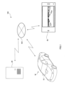
- FIG. 1 is a schematic diagram showing an overview of a communication system according to an embodiment of the present invention
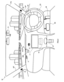
- FIG. It is a figure which shows the structure of the front seat part of the vehicle which concerns on an Example.
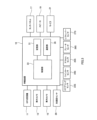
- 1 is a block diagram showing an example of a configuration of an in-vehicle device according to an embodiment
- FIG. 1 is a block diagram showing an example of the configuration of a server device according to an embodiment
- FIG. 1 is a front view of an external device according to an embodiment
- FIG. 1 is a block diagram showing an example of the configuration of an external device according to an embodiment
- FIG. 4 is a flow chart showing an example of a routine executed by the in-vehicle device according to the embodiment; 4 is a flow chart showing an example of a routine executed by the server device according to the embodiment;
- FIG. 5 is a diagram showing an example of a display screen displayed on an external device according to the embodiment;
- FIG. 10 is a diagram showing another example of a display screen displayed on the external device according to the embodiment;
- FIG. 11 is a block diagram showing an example of the configuration of an in-vehicle device according to a modified example of the embodiment;
- FIG. 1 shows a communication system 100 that is an embodiment of the invention.
- the communication system 100 includes an in-vehicle device 10 , a server 40 and an external device 50 .
- FIG. 1 shows a case in which the in-vehicle device 10 is mounted in an automobile M as an example of a moving body.
- FIG. 1 shows a smartphone as an example of the external device 50 .
- the in-vehicle device 10, the server 40, and the external device 50 can mutually transmit and receive data via the network NW using a communication protocol such as TCP/IP or UDP/IP.
- a communication protocol such as TCP/IP or UDP/IP.
- the network NW can be constructed by Internet communication including, for example, a mobile communication network, wireless communication such as Wi-Fi (registered trademark), and wired communication.
- audio-visual communication is possible in which audio and video in the vehicle M acquired by the in-vehicle device 10 as the first device that moves with the vehicle M are transmitted to the external device 50 as the second device.
- the video captured in the car M is transmitted from the in-vehicle device 10 to the external device 50.
- video communication By performing such video communication, the user of the external device 50 viewing the video transmitted from the in-vehicle device 10 can ride in the vehicle M with the driver of the vehicle M as the operator of the mobile body. You can get the feeling that you are In other words, video communication enables the user of the external device 50 to virtually ride in the car M with the user.
- a system such as the communication system 100 of this embodiment that can realize such video communication is also called a virtual co-riding system.
- a user of the external device 50 is also called a virtual fellow passenger.
- the in-vehicle device 10 is a car navigation device
- the in-vehicle device 10 receives from the user a destination to which the user wishes to be guided, transmits the destination to the server 40, and the server 40 generates a route to the destination.
- a terminal device for a car navigation device An example of a terminal device for a car navigation device will be described.
- the virtual fellow passenger provides route guidance to the driver of the automobile M during video communication by the communication system 100.
- FIG. The virtual fellow passenger guides the route using images and sounds output by the external device 50 through video communication.
- FIG. 2 is a perspective view showing the vicinity of the front seats of the automobile M equipped with the in-vehicle device 10 as a video transmission device or video generation device.
- FIG. 1 as an installation example, the case where the in-vehicle device 10 is installed in the dashboard DB of the front seat of the automobile M is shown.
- the GPS receiver 11 is a device that receives signals (GPS signals) from GPS (Global Positioning System) satellites.
- GPS Global Positioning System
- the GPS receiver 11 is arranged on the dashboard DB, for example.
- the GPS receiver 11 may be placed anywhere as long as it can receive GPS signals.
- the GPS receiver 11 can transmit the received GPS signal to the in-vehicle device 10 .
- the vehicle exterior camera 13 is an imaging device that captures the front of the vehicle M.
- the exterior camera 13 is arranged on the dashboard DB so that the forward direction is the photographing direction.
- the vehicle exterior camera 13 is a wide-angle camera, and can photograph a wide area in front of the automobile M through the windshield.
- the exterior camera 13 may be provided on the rearview mirror RM, or may be attached to the inside of the windshield FG.
- the in-vehicle camera 15 is an imaging device that captures the situation inside the automobile M.
- the in-vehicle camera 15 is provided on the upper end of the windshield FG or on the ceiling near the upper end, and is capable of photographing the driver of the automobile M.
- images captured by the vehicle exterior camera 13 or the vehicle interior camera 15 are transmitted to the external device 50 .
- the touch panel 17 is, for example, a touch panel monitor in which a display such as a liquid crystal display capable of displaying images and a touch pad are combined.
- the touch panel 17 is arranged, for example, on the center console of the dashboard DB.
- the touch panel 17 may be arranged at a place that can be visually recognized by the driver and can be reached by the driver.
- the touch panel 17 may be attached on the dashboard DB.
- the touch panel 17 can perform screen display based on the control of the in-vehicle device 10. Further, the touch panel 17 can transmit to the in-vehicle device 10 a signal representing an input operation to the touch panel 17 received from the user. For example, the touch panel 17 may display guidance for car navigation. In addition, operations related to the car navigation function, such as setting a destination, may be possible via the touch panel 17 .
- the touch panel 17 may display information related to video communication, and may display an operation reception screen for starting or ending connection for video communication (hereinafter also referred to as video connection). .
- the occupant of the automobile M may perform a video communication connection operation by performing an input operation on the touch panel 17 .
- the speaker 19 is provided, for example, on the interior side of the A-pillar AP.
- the speaker 19 can emit sounds such as music and voice under the control of the in-vehicle device 10 .
- the speaker 19 emits sound from the external device 50 in a voice call.
- the microphone 21 is a microphone device that receives sound inside the vehicle, and is arranged on the dashboard DB, for example.
- the microphone 21 may be provided anywhere, such as the rearview mirror RM or the steering wheel, as long as it can receive the sound inside the vehicle.
- the sound picked up by the microphone 21 is transmitted to the external device 50 as the sound of the voice call.
- an operation input for starting or ending video communication may be performed by voice via the microphone 21 .
- the steering wheel 23 is a member that receives a steering operation for steering the automobile M.
- the steering wheel 23 is provided rotatably with respect to the dashboard DB. When the steering wheel 23 is rotated, the wheels serving as steering wheels of the automobile M are rotated accordingly.
- the blinker lever 24 is provided near the steering wheel 23 and is a member that receives an operation for turning on the blinker (direction indicator).
- the winker system including the winker lever 24 and the winker is configured such that when the winker lever 24 is operated, the left or right winker lights depending on the direction of operation.
- the accelerator pedal 25 is provided at the foot of the driver's seat, and is a member that receives an operation related to control of a motor such as an engine or a motor for running the automobile M by a stepping action by the driver. That is, the accelerator pedal 25 is a member that receives a steering operation related to acceleration and deceleration of the automobile M. As shown in FIG.
- the brake pedal 26 is provided at the foot of the driver's seat, and is a member that receives an operation related to brake control of the automobile M by a stepping action by the driver. That is, the brake pedal 26 is a member that receives a steering operation related to deceleration of the automobile M. As shown in FIG.
- the shift lever 27 is provided on the center console of the automobile M, and is a member that receives an operation for shifting gears according to the driving conditions of the automobile M.
- FIG. 3 is a block diagram showing the configuration of the in-vehicle device 10.
- the in-vehicle device 10 is a device in which a storage unit 31, a control unit 33, and a communication unit 35 work together via a system bus.
- An acceleration sensor 29 is mounted on the automobile M.
- the acceleration sensor 29 may be, for example, a MEMS acceleration sensor capable of measuring the acceleration of the vehicle M and outputting a signal indicating the measured acceleration.
- the acceleration sensor 29 may be an inertial measurement unit (IMU).
- the acceleration sensor 29 may be built in the in-vehicle device 10 .
- the storage unit 31 is a storage device configured by, for example, a hard disk device, SSD (solid state drive), flash memory, or the like.
- the storage unit 31 stores various programs executed in the in-vehicle device 10, such as an operating system and terminal software.
- Various programs may be obtained via a network from another server device or the like, or may be recorded on a recording medium and read via various drive devices.
- various programs stored in the storage unit 31 can be transmitted via a network, or can be recorded on a computer-readable recording medium and transferred.
- the storage unit 31 also stores map information including road maps.
- the storage unit 31 also stores information indicating the contact address of the external device 50 with which the in-vehicle device 10 performs video communication, such as information such as a telephone number or an e-mail address. Further, the information indicating the contact information may be associated with an identifier such as a nickname that can identify the virtual fellow passenger who is the user of the external device 50 .
- the control unit 33 is composed of a CPU (Central Processing Unit), ROM (Read Only Memory), RAM (Random Access Memory), etc., and functions as a computer.
- the control unit 33 realizes various functions by reading and executing various programs stored in the ROM or the storage unit 31 by the CPU.
- the control unit 33 performs a function of presenting information regarding the start and end of video communication to the driver, a function of transmitting images during video communication, a car navigation function, and the like.
- the control unit 33 is communicably connected to various devices provided in the automobile M, such as an exterior camera 13, an interior camera 15, a touch panel 17, a speaker 19, a microphone 21, and an acceleration sensor 29.
- the control unit 33 sequentially acquires images captured by the vehicle exterior camera 13 and the vehicle interior camera 15 .
- the control unit 33 also sequentially acquires the signal from the GPS receiver 11 and the signal indicating the acceleration measured by the acceleration sensor 29 .
- control unit 33 is communicably connected to various sensors that detect the state of the driving operation of the automobile M, and can acquire sensor information from the various sensors as information indicating the state of the driving operation of the automobile M. be.
- control unit 33 can acquire sensor information from the steering sensor 23S, which is a sensor that detects physical quantities related to manipulation such as the amount of rotation of the steering wheel 23, the direction of rotation, and the torque.
- the steering sensor 23S is a sensor that detects physical quantities related to manipulation such as the amount of rotation of the steering wheel 23, the direction of rotation, and the torque.
- the control unit 33 can acquire sensor information from the turn signal sensor 24S, which is a sensor that detects the operating state such as the operating direction of the turn signal lever.
- the control unit 33 can acquire sensor information from an accelerator sensor 25S, which is a sensor that detects physical quantities related to operations such as the movement amount and movement speed of the accelerator pedal 25.
- the control unit 33 can acquire sensor information from the brake sensor 26S, which is a sensor that detects physical quantities related to operation such as the movement amount and movement speed of the brake pedal 26.
- the control unit 33 receives sensor information from a shift lever sensor 27S that detects which shift position the shift lever 27 is in, such as P (parking), R (reverse), N (neutral), and D (drive). It is obtainable.
- the communication unit 35 is a communication device that transmits and receives data to and from an external device according to instructions from the control unit 33.
- the communication unit 35 is, for example, a NIC (Network Interface Card) for connecting to the network NW.
- NIC Network Interface Card
- the communication unit 35 is connected to the network NW described above, and transmits and receives various data to and from the server 40.
- the communication unit 35 also transmits and receives various data to and from the external device 50 via the server 40 .
- the communication unit 35 transmits to the server 40, for example, images of the exterior or interior of the automobile M, information indicating input operations performed on the in-vehicle device 10, current position information, movement routes, and the like. Further, the communication unit 35 receives, from the server 40, information for displaying on the touch panel 17 regarding video communication, for example.
- control unit 33 sequentially transmits images captured by the vehicle exterior camera 13 or the vehicle interior camera 15 to the server 40 via the communication unit 35 .
- control unit 33 sequentially transmits to the server 40 sensor information acquired from various sensors that detect the state of driving operation of the automobile M via the communication unit 35 .
- the control unit 33 receives display information regarding the start and end of video communication from the server 40 via the communication unit 35 and displays it on the touch panel 17 . Further, the control unit 33 may output information regarding the start and end of video communication from the speaker 19 by voice.
- the control unit 33 can transmit information indicating instructions regarding the start and end of video communication received via the touch panel 17 or the microphone 21 to the server 40 via the communication unit 35, for example.
- control unit 33 of the in-vehicle device 10 supplies the server 40 via the communication unit 35 with position specifying information as position data capable of specifying the current position of the in-vehicle device 10, that is, the current position of the automobile M in this embodiment. Information can be sent.
- control unit 33 can transmit information including the destination input by the user to the server 40 via the communication unit 35, and receive route information or navigation information to the destination from the server 40. is.
- the control unit 33 can transmit audio data of audio picked up by the microphone 21 to the external device 50 via the communication unit 35 for voice communication in video communication. Also, the control unit 33 can receive voice data of voice input to the external device 50 for voice communication in video communication via the communication unit 35 .
- FIG. 4 is a block diagram showing the configuration of the server 40.
- the server 40 is a device in which a storage section 41, a communication section 43, and a control section 45 cooperate via a system bus.
- the server 40 has a function like a SIP server that establishes a voice call between the in-vehicle device 10 and the external device 50 and transfers data of the voice call during video communication.
- the server 40 receives from the in-vehicle device 10 the position specifying information of the vehicle M and the information of the destination set by the user who is the passenger of the vehicle M, and based on the position specifying information and the information of the destination. It has a function to generate a route to
- the storage unit 41 is composed of, for example, a hard disk device and an SSD (solid state drive), and stores various programs such as an operating system and software for the server 40.
- Various programs may be obtained via a network from another server device or the like, or may be recorded on a recording medium and read via various drive devices. That is, the various programs stored in the storage unit 41 can be transmitted via a network, or recorded on a computer-readable recording medium and transferred.
- the storage unit 41 stores, for example, a communication program for the server 40 to transmit the video and driving operation information acquired by the in-vehicle device 10 to the external device 50 .
- the storage unit 41 also stores a map information database (not shown) in which map information including road maps is stored.
- the map information of the map information database is a database having information equivalent to map information used in, for example, a navigation device.
- the communication unit 43 is connected to the network NW described above, and transmits and receives various data to and from the in-vehicle device 10 and the external device 50 .
- the control unit 45 is composed of a CPU (Central Processing Unit), ROM (Read Only Memory), RAM (Random Access Memory), etc., and functions as a computer. Various functions are realized by the CPU reading and executing various programs stored in the ROM and the storage unit 41 .
- CPU Central Processing Unit
- ROM Read Only Memory
- RAM Random Access Memory
- control unit 45 implements audio-visual communication for transmitting the audio and video of the vehicle M acquired by the in-vehicle device 10 to the external device 50 .
- control unit 45 transfers video and audio received from the in-vehicle device 10 to the external device 50 via the communication unit 43, and transfers audio received from the external device 50 to the in-vehicle device 10, thereby performing video communication.
- the control unit 45 includes a video acquisition unit 46, a driving operation information acquisition unit 47, and a display control unit 48.
- the image acquisition unit 46 is a functional unit that executes an image acquisition step of sequentially acquiring images captured in the automobile M.
- the image acquisition unit 46 sequentially receives images of the front of the vehicle M captured by the exterior camera 13 provided in the vehicle M from the in-vehicle device 10 via the communication unit 43, and obtains the images. Obtained sequentially.
- the image acquisition unit 46 sequentially receives, through the communication unit 43, the image captured by the exterior camera 13 and the image captured by the interior camera 15 of the driver of the vehicle M. You may acquire the image
- the driving operation information acquisition unit 47 is a functional unit that executes a driving operation information acquisition step for sequentially acquiring driving operation information as the driving operation information indicating the driving operation of the vehicle M by the driver of the vehicle M.
- the driving operation information acquisition unit 47 sequentially receives, as driving operation information, signals from various sensors that detect the state of the driving operation of the vehicle M from the in-vehicle device 10 via the communication unit 43, thereby obtaining driving operation information. Get information sequentially.
- the driving operation information acquisition unit 47 obtains, as driving operation information, the rotation direction and rotation angle of the steering wheel 23, the operation state of the turn signal lever 24, the operation state such as the amount and speed of movement of the accelerator pedal 25, and the operation state of the brake pedal 26.
- Information indicating at least one of the operation state such as the movement amount and movement speed of the shift lever 27 and the operation state of the shift lever 27 is sequentially acquired.
- the driving operation information acquisition unit 47 may sequentially acquire the signal from the GPS receiver 11 and the signal indicating the acceleration measured by the acceleration sensor 29 as the driving operation information.
- the driving operation information acquisition unit 47 acquires the driving conditions of the vehicle M, such as position information acquired based on GPS signals and the speed of the vehicle M acquired based on signals indicating acceleration from the acceleration sensor 29. You may obtain the information shown.
- the display control unit 48 performs display control to display both the image acquired by the image acquisition unit 46 and the display based on the driving operation information acquired by the driving operation information acquisition unit 47 on the external device 50. It is a functional part that executes
- the display control unit 48 generates display information by combining an image of the front of the automobile M captured by the exterior camera 13 and a display based on the driving operation information, and outputs the generated display information to the external device 50. sequentially sent to
- the display control unit 48 generates, for example, display information for superimposing and displaying an image of the front of the automobile M and a display based on the driving operation information.
- the display control unit 48 may, for example, generate display information for displaying a video image of the front of the automobile M and a display based on the driving operation information in separate areas side by side.
- the display control unit 48 when the display control unit 48 generates the display information for displaying both the image and the display based on the driving operation information, the time when the image is acquired and the time when the signal is detected in the in-vehicle device 10 match the
- the display control unit 48 executes the display control step, for example, the operating state of the steering wheel 23, the operating state of the turn signal lever 24, the operating state of the accelerator pedal 25, the operating state of the brake pedal 26, and the operating state of the shift lever 27 is displayed on the external device 50 together with the image captured in the automobile M.
- the display may be based on information indicating the driving situation of the vehicle M, such as the position information and speed of the vehicle M.
- the display based on the driving operation information and the display based on the driving situation allow the user of the external device 50 to obtain information that can be obtained by, for example, actually riding in the front passenger seat of the automobile M.
- video communication is performed using the external device 50, it is possible to supplement information that cannot be obtained by a video of the front of the vehicle M and a call with the driver of the vehicle M.
- the direction and angle of rotation of the steering wheel 23 can be determined visually through the operation of the driver. - Whether the lever 24 is operated left or right can be grasped visually by an actual fellow passenger. However, it is difficult to obtain such information from images of video communication, and it is difficult for the virtual fellow passenger to grasp such information.
- control unit 45 acquires position information indicating the current position of the automobile M from the in-vehicle device 10 via the communication unit 43 .
- control unit 45 acquires destination information input to the in-vehicle device 10 by the occupant of the vehicle M from the in-vehicle device 10 via the communication unit 43 .
- the control unit 45 generates a route to the destination based on the position information and the destination information, and transmits information indicating the route to the in-vehicle device 10 .
- FIG. 5 is a front view of the external device 50.
- the external device 50 is a smart phone.
- the touch panel 51 is, for example, a touch panel monitor that combines a display such as a liquid crystal display capable of displaying images and a touch pad.
- the touch panel 51 can generate a signal representing an input operation to the touch panel 51 received from the user.
- the touch panel 51 displays an image transmitted from the in-vehicle device 10 .
- touch panel 51 information about video communication is displayed, and an operation reception screen for starting connection of video communication is displayed.
- a user of the external device 50 can perform an input operation for starting video communication by performing an input operation on the touch panel 51 .
- the speaker 53 can emit sounds such as music and voice. During video communication, the speaker 53 emits sound from the in-vehicle device 10 in a voice call.
- the microphone 55 is a microphone device that receives sound emitted toward the external device 50 . During video communication, the sound picked up by the microphone 55 is transmitted to the in-vehicle device 10 via the server 40 as the sound of the voice call.
- FIG. 6 is a block diagram showing an example of the configuration of the external device 50.
- the external device 50 is a device in which a storage section 57, a control section 59, and a communication section 61 cooperate via a system bus (not shown).
- the storage unit 57 is composed of, for example, a hard disk device, SSD (solid state drive), flash memory, etc., and stores various programs such as an operating system and software for the external device 50 .
- the various programs may be obtained, for example, from another server device or the like via a network, or may be recorded on a recording medium and read via various drive devices. That is, the various programs stored in the storage unit 57 can be transmitted via a network, or recorded on a computer-readable recording medium and transferred.
- the control unit 59 is composed of a CPU (Central Processing Unit), ROM (Read Only Memory), RAM (Random Access Memory), etc., and functions as a computer. Various functions are realized by the CPU reading and executing various programs stored in the ROM and the storage unit 57 .
- CPU Central Processing Unit
- ROM Read Only Memory
- RAM Random Access Memory
- the control unit 59 is communicably connected to the touch panel 51, the speaker 53 and the microphone 55.
- the control unit 59 can receive a signal indicating an input operation to the touch panel 51 and a voice input signal from the microphone 55 .
- the control unit 59 can receive a request to start or end video communication from the user via the touch panel 51 or the microphone 55 .
- control unit 59 can transmit a video or image signal to the touch panel 51 for display, or transmit an audio signal to the speaker 53 to output sound.
- control unit 59 causes the touch panel 51 to display a start screen for accepting a request for a video communication connection attempt.
- control unit 59 causes the touch panel 51 to display an image during the video communication, and causes the speaker 53 to output the sound collected in the automobile M during the video communication.
- the communication unit 61 is connected to the network NW described above, and transmits and receives various data to and from the server 40. In addition, the communication unit 61 transmits and receives various data including video transmitted from the in-vehicle device 10 to and from the in-vehicle device 10 via the server 40 .
- the control unit 59 of the external device 50 can receive, via the communication unit 61, information for displaying a start screen for accepting a connection trial request for video communication.
- control unit 59 can transmit audio data of audio picked up by the microphone 55 to the in-vehicle device 10 via the communication unit 61 for voice communication in video communication.
- control unit 59 can receive voice data transmitted from the in-vehicle device 10 via the communication unit 61 for voice communication in video communication.
- control unit 59 of the external device 50 can receive position specifying information capable of specifying the current position of the vehicle M transmitted from the in-vehicle device 10 from the server 40 via the communication unit 61 . Further, for example, the control unit 59 can receive route information or navigation information of the automobile M from the server 40 via the communication unit 61 .
- FIG. 7 is a flowchart showing a video transmission routine RT1 executed by the control unit 33 of the in-vehicle device 10.
- FIG. 7 For example, when the in-vehicle device 10 is powered on, the control unit 33 starts the video transmission routine RT1.
- step S101 the control unit 33 determines whether video communication has started (step S101).
- the determination in step S ⁇ b>101 is made, for example, based on whether the in-vehicle device 10 is connected for video communication and communication with the external device 50 is established.
- step S101 when the control unit 33 determines that the video communication has not started (step S101: NO), it ends the video transmission routine RT1 and newly starts the next video transmission routine RT1.
- step S101 when the control unit 33 determines that video communication has started (step S101: YES), it starts transmitting the image and driving operation information acquired in the automobile M (step S102).
- control unit 33 starts transmitting the image captured by the exterior camera 13 to the server 40 . Further, in step 102, for example, the control unit 33 sequentially transmits sensor information from various sensors that detect the state of the driving operation of the automobile M.
- step 102 the control unit 33 determines the rotation direction and rotation angle of the steering wheel 23, the operation state of the turn signal lever 24, the operation state such as the amount and speed of movement of the accelerator pedal 25, the amount and speed of movement of the brake pedal 26, and the like.
- Information indicating at least one of the operating state such as the moving speed and the operating state of the shift lever 27 is sequentially transmitted.
- control unit 33 may sequentially transmit the signal from the GPS receiver 11 and the signal indicating the acceleration measured by the acceleration sensor 29.
- step S103 the control unit 33 determines whether or not the video communication has ended.
- step S ⁇ b>103 for example, when the in-vehicle device 10 is not connected for video communication and communication with the external device 50 is not established, it is determined that the video communication has ended.
- step S103 if the control unit 33 determines that the video communication has not ended (step S103: NO), it repeats step S103 and determines again whether the video communication has ended.
- step S103 when the control unit 33 determines that the video communication has ended (step S103: YES), it ends the transmission of the image and the driving operation information (step S104).
- control unit 33 After executing step S104, the control unit 33 terminates the video transmission routine RT1 and newly starts the next video transmission routine RT1.
- FIG. 8 is a flowchart showing a display control routine RT2 executed by the display control section 48 of the control section 45 of the server 40.
- the display control unit 48 starts the display control routine RT2, for example, when a notification indicating that video communication is to be performed between the in-vehicle device 10 and the external device 50 is made via the server 40 .
- step S201 the display control unit 48 determines whether video communication has been started. The determination in step S ⁇ b>201 is made based on, for example, whether or not video communication connection is established between the in-vehicle device 10 and the external device 50 and communication with the external device 50 is established.
- step S201 when the display control unit 48 determines that video communication has not started (step S201: NO), step S201 is repeated to determine again whether or not video communication has started.
- step S201 when the display control unit 48 determines that video communication has started (step S201: YES), it starts receiving images and driving operation information from the in-vehicle device 10 (step S202).
- step S202 for example, the display control unit 48 starts receiving images captured by the exterior camera 13 of the automobile M, and receives sensor information from various sensors that detect the state of the driving operation of the automobile M. Start.
- step S202 for example, the display control unit 48 outputs, as driving operation information, the rotation direction and rotation angle of the steering wheel 23, the operation state of the turn signal lever 24, the operation state such as the amount and speed of movement of the accelerator pedal 25, and the operation state of the brake pedal 25.
- Information indicating at least one of the operation state such as the movement amount and movement speed of the pedal 26 and the operation state of the shift lever 27 is sequentially received.
- step S202 the display control unit 48 may sequentially receive the signal from the GPS receiver 11 and the signal indicating the acceleration measured by the acceleration sensor 29 as the driving operation information.
- step S202 the display control unit 48 starts generating and transmitting a driving operation display image, which is a combined image of the received image and the display based on the driving operation information (step S203).
- step S203 the display control unit 48 displays, for example, the operation state of the steering wheel 23, the turn signal lever 24, the accelerator pedal 25, the brake pedal 26, or the shift lever 27 in the image of the front of the automobile M.
- Display information to be superimposed and displayed is sequentially generated as a driving operation display image, and the sequentially generated driving operation display image is sequentially transmitted to the external device 50 .
- FIG. 9 is a diagram showing an example of a driving operation display image displayed on the touch panel 51 of the external device 50 when step S203 is executed.
- the touch panel 51 displays a so-called horizontal screen display in which the longitudinal direction of the touch panel 51 is the horizontal direction.
- the touch panel 51 is divided into two display areas, a first display area AR1 and a second display area AR2 that occupies a smaller area than the first display area AR1. ing.
- a display based on driving operation information is superimposed on an image of the front of the automobile M and displayed.
- an arrow-shaped icon indicating the pointing direction of the winker lever 24 is displayed as the operation state of the winker lever 24 in the area A surrounded by the dashed line.
- the icon indicates that the winker lever 24 is being operated so that the left winker lights up.
- an icon indicating the operation state of the steering wheel 23 is displayed in an area B surrounded by a dashed line.
- the icon indicates an operating state in which the steering wheel 23 is rotated to the left.
- an area C surrounded by a dashed line displays the operating state of the accelerator pedal 25 .
- an icon indicating the accelerator pedal and a gauge indicating the accelerator opening are displayed.
- an area D surrounded by a dashed line displays the operating state of the brake pedal 26 .
- an icon indicating the brake pedal and a gauge indicating the amount of depression of the brake pedal are displayed.
- an area E surrounded by a dashed line shows the operating state of the shift lever 27.
- an area E displays an icon indicating the shift lever and characters indicating which shift position the shift lever 27 is in when it is operated.
- "D" indicating the drive shift position is displayed.
- an area F surrounded by a dashed line displays the speed of the automobile M.
- the current speed of the automobile M is displayed along with an icon indicating a speedometer.
- a map image showing the current position PL of the vehicle M and the moving route R of the vehicle M is displayed in the second display area AR2.
- the virtual fellow passenger can see the map image displayed in the second display area AR2 to confirm the movement route R of the vehicle M, and use the image in front of the vehicle M and the driving operation information as clues to guide the route. It can be performed.
- an actual fellow passenger gets into the car M together with the driver of the car M and gives directions, he or she can grasp the driver's driving operation state by sight, hearing, or the like.
- the actual fellow passenger indicates how much the driver is turning the steering wheel 23 left or right, whether the driver has operated the turn signal lever 24, and if so, which direction is left or right. It is possible to collect information in the car M such as whether or not
- the user of the external device 50 as a virtual fellow passenger does not get on the car M, but uses video communication to guide the route while watching the image captured by the outside camera 13 outside the car M. For example, it is impossible to grasp the driving operation state such as the operation state of the steering wheel 23 or the turn signal lever 24 by the driver.
- the display based on the driving operation information such as the display indicating the rotation state of the steering wheel 23 and the indication direction of the turn signal lever 24 is displayed on the external device 50 based on the driving device information.
- the virtual fellow passenger can smoothly perform route guidance with a feeling close to that of actually riding in the automobile M.
- the display control unit 48 sequentially acquires the sequentially acquired images and the driving operation information, immediately generates the driving operation display image, and sequentially transmits it to the external device 50, so that the state of the driving operation of the automobile M can be displayed. It can be displayed on the external device 50 in real time.
- the virtual passenger can give advice on directions without any time lag. For example, when the driver of the car M is approaching the point where the left turn should be made but does not operate to turn the turn signal to the left, the virtual passenger warns the driver to "turn left there.” It is possible to prevent a situation in which the automobile M passes the place where the left turn should be made without making a left turn.
- the virtual fellow passenger can easily feel as if he or she is riding in the automobile M. You can get the feeling of driving.
- FIG. 9 the case where the display based on the driving operation information is superimposed on the image taken in front of the automobile M has been described, but the present invention is not limited to this, and the image taken in the automobile M is displayed.
- a display based on the driving operation information may be made in a region different from the region where the driving operation information is displayed.
- step S203 the display control unit 48 determines whether or not the video communication has ended (step S204).
- step S204 if the display control unit 48 determines that the video communication has not ended (step S204: NO), it repeats step S204 and determines again whether the video communication has ended.
- step S204 when the display control unit 48 determines that the video communication has ended (step S204: YES), it ends the generation and transmission of the driving operation display image (step S205), and receives the image and the driving operation information. After finishing (step S206), the display control routine RT2 ends.
- FIG. 10 is a diagram showing another example of the driving operation display image displayed on the touch panel 51 of the external device 50 when step S203 of the display control routine RT2 is executed.
- the touch panel 51 provides a so-called vertical screen display in which the longitudinal direction of the touch panel 51 is the vertical direction.
- the touch panel 51 has a third display area AR3 displaying an image of the front of the automobile M, and a map image, which is larger than the third display area AR3.
- the display is divided into two display areas, ie, a fourth display area AR4 that occupies the range. According to the vertical screen display shown in FIG. 10, the user of the external device 50 can clearly see the map image.
- the user of the external device 50 may switch between the horizontal screen display shown in FIG. 9 and the vertical screen display shown in FIG.
- the user of the external device 50 can display a horizontal screen as shown in FIG. 9 on the touch panel 51 so that the user can get a sense of riding together with the driver and can provide route guidance close to reality.
- the user of the external device 50 can guide the route while carefully checking the map by displaying the vertical screen on the touch panel 51 as shown in FIG.
- the communication system 100 of the present embodiment includes the in-vehicle device 10 as the first device that moves together with the automobile M as the moving object and the external device 50 as the second device via the server 40. It is possible to establish a voice call between the vehicle and the vehicle, and to perform video communication to transmit the image of the moving body on which the in-vehicle device 10 is mounted to the external device 50 .
- the communication system 100 of the present embodiment includes an image acquisition unit that sequentially acquires images captured in a mobile body, and a steering operation information acquisition unit that sequentially acquires steering operation information indicating a steering operation to the mobile body by the operator of the mobile body. and Further, the communication system 100 of the present embodiment has a display control unit that performs display control to display both the image and the display based on the steering operation information on the second device.
- the display control unit can, for example, sequentially display both the sequentially acquired images and the display based on the sequentially acquired maneuvering operation information, and can present the maneuvering operation information to the user of the second device in real time. can.
- the user of the second device outside the mobile body in communication between the first device inside the mobile body and the second device outside the mobile body, the user of the second device outside the mobile body can obtain A communication system, a communication device, a server device, a communication method, a communication program and a storage medium capable of providing information can be provided.
- FIG. 11 is a block diagram showing an example configuration of an in-vehicle device 70 as a communication device in a modification of the communication system 100 of the embodiment.
- the in-vehicle device 70 has the functions of the video acquisition unit 46, the driving operation information acquisition unit 47, and the display control unit 48 that the server 40 has in the above embodiment.
- control unit 71 of the in-vehicle device 70 has a video acquisition unit 73 , a driving operation information acquisition unit 74 , and a display control unit 75 .
- the image acquisition unit 73 sequentially acquires images captured by the exterior camera 13 .
- the image acquisition unit 73 may sequentially acquire the image captured by the in-vehicle camera 15 together with the image captured by the exterior camera 13 .
- the driving operation information acquisition unit 74 sequentially acquires signals from various sensors that detect the state of the driving operation of the automobile M as the driving operation information.
- the display control unit 75 performs display control to display both the image acquired by the image acquisition unit 73 and the display based on the driving operation information acquired by the driving operation information acquisition unit 74 on the external device 50. to run.
- the display control unit 75 controls, for example, the image of the front of the automobile M captured by the exterior camera 13 and sequentially acquired by the image acquisition unit 73, and the driving operation information sequentially acquired by the driving operation information acquisition unit 74. display information based on the display information is generated, and the generated display information is sequentially transmitted to the external device 50 .
- the storage unit 77 sequentially acquires images captured in the automobile M, sequentially acquires driving operation information indicating the driving operation of the automobile M by the driver of the automobile M, and displays the images and the driving operation information.
- a communication program is stored for the control unit 71 to execute display control for displaying both of and on the external device 50 .
- the video communication in this modification may be performed directly between the in-vehicle device 70 and the external device 50 by P2P (Peer to Peer) communication or the like without going through the server 40 .
- P2P Peer to Peer
- the configurations, routines, and the like of the in-vehicle device 10, the in-vehicle device 70, the server 40, and the external device 50 in the above-described embodiment and modification are merely examples, and can be appropriately selected or changed according to the application.
- the image displayed on the touch panel 51 of the external device 50 is between the image captured by the exterior camera 13 and the image captured by the interior camera 15.
- the switching may be made possible by operating the in-vehicle device 10 .
- the display based on the driving operation information such as the display indicating the operating state of the steering wheel and the operating state of the turn signal lever.
- the display may be hidden at least part of.
- the external device 50 may display a display indicating the operation state of the turn signal lever and emit a turn signal sound.
- the winker sound picked up by the microphone 21 provided in the automobile M may be controlled to be synchronized with the display indicating the operating state of the winker lever and output from the external device 50 .
- a learning model or the like may be used to discriminate between the blinker sound and other sounds.
- a predetermined turn signal sound prepared in advance may be output from the external device 50 together with a display indicating the operating state of the turn signal lever. .
- the actual turn signal sound picked up by the microphone 21 provided in the automobile M may be canceled.
- the display indicating the operating state of the turn signal may be made to blink, and the turn signal sound and the blinking of the display may be synchronized.
- the driving operation information in the above embodiment is not limited to the information illustrated in the embodiment, and may include other information indicating the driving operation to the automobile M.
- the driving operation information may include information indicating handbrake operation, wiper operation, headlight switch operation, and the like.
- the present invention is not limited to this.
- the virtual fellow passenger can grasp the details of the driving operation by the driver of the automobile M when the driving operation information is displayed together with the image captured while in the automobile M, even if the route guidance is not provided. can be increased.
- the present invention performs audio-visual communication in which audio and video in the vehicle M acquired by the in-vehicle device 10 as the first device moving with the vehicle M are transmitted to the external device 50 as the second device.
- the present invention can also be applied to communications in which voice is not transmitted from the external device 50 .
- the in-vehicle device 10 and the external device 50 do not necessarily have to be able to make a voice call.
- the mode of communication between the in-vehicle device 10 and the external device 50 is simply communication from the in-vehicle device 10 to the external device 50 without a two-way voice call, such as YouTube (registered trademark) or Niconico Live Broadcasting (registered trademark).
- a mode in which video and audio are distributed may be used.
- video communication is performed between the in-vehicle device 10 and the external device 50 via the server 40, but the video communication may be performed directly between the in-vehicle device 10 and the external device 50. good.
- a voice call is established between the in-vehicle device 10 and the external device 50 in parallel through a path different from the communication system 100. It's okay to be there.
- the in-vehicle device 10 is an in-vehicle navigation device, but the in-vehicle device 10 only needs to be able to distribute video from the exterior camera 13 or the interior camera 15.
- the in-vehicle device 10 may have a configuration in which a terminal device having the same configuration as the in-vehicle device 10, the exterior camera 13, and the touch panel 17 are integrated.
- the in-vehicle device 10 may be a terminal device such as a camera-equipped smartphone, tablet, or PC, in which an application that exhibits the same functions as the in-vehicle device 10 is installed.
- the in-vehicle device 10 can be mounted on the dashboard DB with a cradle or the like, for example, so that the built-in camera can photograph the front of the automobile M through the windshield of the automobile M.
- the in-vehicle device 10 may be configured not to display the screen presented to the driver of the automobile M.
- the in-vehicle device 10 may have a configuration like a drive recorder, and may be a device integrated with the vehicle exterior camera 13, for example.
- the in-vehicle device 10 may be, for example, a device in which hardware that performs the video communication function of the above-described in-vehicle device 10 is built in the housing of the exterior camera 13 . In this case, the in-vehicle device 10 may not perform various display outputs as described above.
- the external device 50 is a terminal device that can be used by the virtual passenger for video communication, presents displays or messages related to video communication, accepts operation inputs necessary for video communication, transmits and receives audio data, and receives video. and display.
- the external device 50 may be a terminal device such as a tablet, a PC, or a wearable terminal.
- the in-vehicle device 10 and the in-vehicle device 70 are mounted in the automobile M has been described. good too.
- the in-vehicle device 10 may be a terminal device with a built-in camera, such as a smart phone, held by a person, and transmitting images by video communication while walking, for example.
Landscapes
- Engineering & Computer Science (AREA)
- Multimedia (AREA)
- Signal Processing (AREA)
- Telephonic Communication Services (AREA)
- Two-Way Televisions, Distribution Of Moving Picture Or The Like (AREA)
- Closed-Circuit Television Systems (AREA)
Priority Applications (3)
| Application Number | Priority Date | Filing Date | Title |
|---|---|---|---|
| JP2023570574A JPWO2023127093A1 (https=) | 2021-12-28 | 2021-12-28 | |
| PCT/JP2021/048782 WO2023127093A1 (ja) | 2021-12-28 | 2021-12-28 | 通信システム、通信装置、サーバ装置、通信方法、通信プログラム及び記憶媒体 |
| JP2025127175A JP2025156424A (ja) | 2021-12-28 | 2025-07-30 | 通信システム、通信装置、サーバ装置、通信方法、通信プログラム及び記憶媒体 |
Applications Claiming Priority (1)
| Application Number | Priority Date | Filing Date | Title |
|---|---|---|---|
| PCT/JP2021/048782 WO2023127093A1 (ja) | 2021-12-28 | 2021-12-28 | 通信システム、通信装置、サーバ装置、通信方法、通信プログラム及び記憶媒体 |
Publications (1)
| Publication Number | Publication Date |
|---|---|
| WO2023127093A1 true WO2023127093A1 (ja) | 2023-07-06 |
Family
ID=86998431
Family Applications (1)
| Application Number | Title | Priority Date | Filing Date |
|---|---|---|---|
| PCT/JP2021/048782 Ceased WO2023127093A1 (ja) | 2021-12-28 | 2021-12-28 | 通信システム、通信装置、サーバ装置、通信方法、通信プログラム及び記憶媒体 |
Country Status (2)
| Country | Link |
|---|---|
| JP (2) | JPWO2023127093A1 (https=) |
| WO (1) | WO2023127093A1 (https=) |
Citations (4)
| Publication number | Priority date | Publication date | Assignee | Title |
|---|---|---|---|---|
| JPH11205782A (ja) * | 1998-01-07 | 1999-07-30 | Toyota Motor Corp | 車両用前方画像処理装置及び車両用前方画像処理システム |
| JP2010211613A (ja) * | 2009-03-11 | 2010-09-24 | Omron Corp | 情報処理装置及び方法、プログラム、並びに情報処理システム |
| JP2017204104A (ja) * | 2016-05-10 | 2017-11-16 | エヌ・ティ・ティ・コミュニケーションズ株式会社 | 制御装置、車載装置、映像配信方法、及びプログラム |
| JP2019156299A (ja) * | 2018-03-15 | 2019-09-19 | 株式会社デンソーテン | 車両遠隔操作装置及び車両遠隔操作方法 |
Family Cites Families (3)
| Publication number | Priority date | Publication date | Assignee | Title |
|---|---|---|---|---|
| JP2003154900A (ja) * | 2001-11-22 | 2003-05-27 | Pioneer Electronic Corp | リアエンタテイメントシステム及びその制御方法 |
| JP2011020539A (ja) * | 2009-07-15 | 2011-02-03 | Panasonic Corp | 後部座席用映像表示装置 |
| WO2020202345A1 (ja) * | 2019-03-29 | 2020-10-08 | 本田技研工業株式会社 | 支援方法、および支援システム |
-
2021
- 2021-12-28 WO PCT/JP2021/048782 patent/WO2023127093A1/ja not_active Ceased
- 2021-12-28 JP JP2023570574A patent/JPWO2023127093A1/ja active Pending
-
2025
- 2025-07-30 JP JP2025127175A patent/JP2025156424A/ja active Pending
Patent Citations (4)
| Publication number | Priority date | Publication date | Assignee | Title |
|---|---|---|---|---|
| JPH11205782A (ja) * | 1998-01-07 | 1999-07-30 | Toyota Motor Corp | 車両用前方画像処理装置及び車両用前方画像処理システム |
| JP2010211613A (ja) * | 2009-03-11 | 2010-09-24 | Omron Corp | 情報処理装置及び方法、プログラム、並びに情報処理システム |
| JP2017204104A (ja) * | 2016-05-10 | 2017-11-16 | エヌ・ティ・ティ・コミュニケーションズ株式会社 | 制御装置、車載装置、映像配信方法、及びプログラム |
| JP2019156299A (ja) * | 2018-03-15 | 2019-09-19 | 株式会社デンソーテン | 車両遠隔操作装置及び車両遠隔操作方法 |
Also Published As
| Publication number | Publication date |
|---|---|
| JP2025156424A (ja) | 2025-10-14 |
| JPWO2023127093A1 (https=) | 2023-07-06 |
Similar Documents
| Publication | Publication Date | Title |
|---|---|---|
| US20160005333A1 (en) | Real Time Car Driving Simulator | |
| CN110877573A (zh) | 车辆周边显示装置 | |
| JP7593806B2 (ja) | 車両操作システム、車両制御装置、車両操作方法及び車両操作プログラム | |
| US9987927B2 (en) | Method for operating a communication device for a motor vehicle during an autonomous drive mode, communication device as well as motor vehicle | |
| JP2018133712A (ja) | 周辺監視装置 | |
| WO2019073938A1 (ja) | 駐車支援装置 | |
| JP2020121638A (ja) | 表示制御装置 | |
| JP2017085410A (ja) | 走行支援装置 | |
| JP2018144567A (ja) | 運転支援装置 | |
| JP7534181B2 (ja) | 車両の表示装置 | |
| JP2014026425A (ja) | 再現システム | |
| WO2023127093A1 (ja) | 通信システム、通信装置、サーバ装置、通信方法、通信プログラム及び記憶媒体 | |
| JP7852526B2 (ja) | 表示制御装置 | |
| WO2018025441A1 (ja) | 周辺監視装置 | |
| JP2018076019A (ja) | 画像処理装置 | |
| JP7754947B2 (ja) | 情報処理装置、情報処理方法、情報処理プログラム及び記憶媒体 | |
| JP2024090801A (ja) | 通信システム、通信装置、サーバ装置、通信方法、通信プログラム及び記憶媒体 | |
| JP7784236B2 (ja) | 映像送信装置、サーバ装置、映像送信方法、映像送信プログラム及び記憶媒体 | |
| JP2019069719A (ja) | 駐車支援装置 | |
| JP2024090876A (ja) | 通信システム、通信装置、サーバ装置、通信方法、通信プログラム及び記憶媒体 | |
| JP7798560B2 (ja) | 通信システム、通信装置、サーバ装置、通信方法、通信プログラム及び記憶媒体 | |
| JP2024091137A (ja) | 情報処理装置、情報処理方法、情報処理プログラム及び記憶媒体 | |
| JP2022157413A (ja) | 映像送信装置、映像生成装置、映像送信方法、映像送信プログラム及び記憶媒体 | |
| JP2026068602A (ja) | 車両遠隔監視システム、車両及び遠隔監視装置 | |
| JP2022093576A (ja) | 表示装置 |
Legal Events
| Date | Code | Title | Description |
|---|---|---|---|
| 121 | Ep: the epo has been informed by wipo that ep was designated in this application |
Ref document number: 21969975 Country of ref document: EP Kind code of ref document: A1 |
|
| WWE | Wipo information: entry into national phase |
Ref document number: 2023570574 Country of ref document: JP |
|
| NENP | Non-entry into the national phase |
Ref country code: DE |
|
| 122 | Ep: pct application non-entry in european phase |
Ref document number: 21969975 Country of ref document: EP Kind code of ref document: A1 |