WO2023120708A1 - 電解コンデンサおよび電解コンデンサの製造方法 - Google Patents
電解コンデンサおよび電解コンデンサの製造方法 Download PDFInfo
- Publication number
- WO2023120708A1 WO2023120708A1 PCT/JP2022/047666 JP2022047666W WO2023120708A1 WO 2023120708 A1 WO2023120708 A1 WO 2023120708A1 JP 2022047666 W JP2022047666 W JP 2022047666W WO 2023120708 A1 WO2023120708 A1 WO 2023120708A1
- Authority
- WO
- WIPO (PCT)
- Prior art keywords
- anode
- cathode
- foil
- holes
- separator
- Prior art date
- Legal status (The legal status is an assumption and is not a legal conclusion. Google has not performed a legal analysis and makes no representation as to the accuracy of the status listed.)
- Ceased
Links
Images


Classifications
-
- H—ELECTRICITY
- H01—ELECTRIC ELEMENTS
- H01G—CAPACITORS; CAPACITORS, RECTIFIERS, DETECTORS, SWITCHING DEVICES, LIGHT-SENSITIVE OR TEMPERATURE-SENSITIVE DEVICES OF THE ELECTROLYTIC TYPE
- H01G9/00—Electrolytic capacitors, rectifiers, detectors, switching devices, light-sensitive or temperature-sensitive devices; Processes of their manufacture
- H01G9/004—Details
- H01G9/008—Terminals
-
- H—ELECTRICITY
- H01—ELECTRIC ELEMENTS
- H01G—CAPACITORS; CAPACITORS, RECTIFIERS, DETECTORS, SWITCHING DEVICES, LIGHT-SENSITIVE OR TEMPERATURE-SENSITIVE DEVICES OF THE ELECTROLYTIC TYPE
- H01G9/00—Electrolytic capacitors, rectifiers, detectors, switching devices, light-sensitive or temperature-sensitive devices; Processes of their manufacture
- H01G9/004—Details
- H01G9/02—Diaphragms; Separators
-
- H—ELECTRICITY
- H01—ELECTRIC ELEMENTS
- H01G—CAPACITORS; CAPACITORS, RECTIFIERS, DETECTORS, SWITCHING DEVICES, LIGHT-SENSITIVE OR TEMPERATURE-SENSITIVE DEVICES OF THE ELECTROLYTIC TYPE
- H01G9/00—Electrolytic capacitors, rectifiers, detectors, switching devices, light-sensitive or temperature-sensitive devices; Processes of their manufacture
- H01G9/004—Details
- H01G9/04—Electrodes or formation of dielectric layers thereon
- H01G9/048—Electrodes or formation of dielectric layers thereon characterised by their structure
-
- H—ELECTRICITY
- H01—ELECTRIC ELEMENTS
- H01G—CAPACITORS; CAPACITORS, RECTIFIERS, DETECTORS, SWITCHING DEVICES, LIGHT-SENSITIVE OR TEMPERATURE-SENSITIVE DEVICES OF THE ELECTROLYTIC TYPE
- H01G9/00—Electrolytic capacitors, rectifiers, detectors, switching devices, light-sensitive or temperature-sensitive devices; Processes of their manufacture
- H01G9/15—Solid electrolytic capacitors
Definitions
- the present disclosure relates to electrolytic capacitors and methods of manufacturing electrolytic capacitors.
- an electrolytic capacitor including a laminate of a plurality of anode foils, a plurality of cathode foils, and a plurality of separators is known.
- their misalignment degrades their properties. Therefore, it is important to stack them so that their positions do not shift.
- Patent Document 1 Japanese Unexamined Patent Application Publication No. 2010-87290 discloses that "through holes are formed in the anode foil and the separator of a capacitor element in which the anode foil and the cathode foil are alternately laminated with a separator interposed therebetween, and the cathode is formed at the through hole.
- Laminated Electrolytic Capacitors in Which Foils are Joined Together Further, Patent Document 1 describes a "laminated type capacitor element in which anode foils and cathode foils are alternately laminated via separators, and through holes are formed in the cathode foils and the separators, and the anode foils are joined at the through holes. electrolytic capacitors.”
- Patent Document 1 discloses a method of connecting anode foils to each other by welding where the cathode foils are present, and connecting the cathode foils to each other at the portions where the anode foils are present.
- Patent Document 1 discloses a method of connecting anode foils to each other by welding where the cathode foils are present, and connecting the cathode foils to each other at the portions where the anode foils are present.
- Patent Document 1 discloses a method of connecting anode foils to each other by welding where the cathode foils are present, and connecting the cathode foils to each other at the portions where the anode foils are present.
- One of the purposes of the present disclosure is to provide an electrolytic capacitor in which the positioning of the members forming the laminated body that becomes the capacitor element is easy.
- the electrolytic capacitor includes at least one anode foil having a dielectric layer formed thereon, at least one cathode foil, and at least one separator disposed between the anode foil and the cathode foil.
- An electrolytic capacitor comprising a laminate, a conductive polymer layer formed in the laminate, an anode lead member, and a cathode lead member, wherein the anode lead member comprises an anode connection portion and the anode connection portion.
- the cathode lead member includes a cathode connection portion; and a plurality of second projections formed on the cathode connection portion; the anode foil and The anode foil and the anode lead member are electrically connected by crimping the plurality of first protrusions penetrating the separator, and the cathode foil and the separator penetrating the separator are electrically connected to each other.
- the cathode foil and the cathode lead member are electrically connected by crimping the plurality of second projections.
- the manufacturing method includes a laminate including at least one anode foil having a dielectric layer formed thereon, at least one cathode foil, and at least one separator;
- a method of manufacturing an electrolytic capacitor including a molecular layer, an anode lead member, and a cathode lead member, wherein the anode lead member includes an anode connection portion and a plurality of first protrusions formed on the anode connection portion.
- the cathode lead member includes a cathode connection portion and a plurality of second projections formed on the cathode connection portion; and the manufacturing method comprises forming a plurality of first through holes in the anode foil.
- the anode foil is electrically connected to the anode lead member by passing one convex portion through the plurality of first through-holes and the plurality of third through-holes and crimping, and the plurality of second through-holes are crimped.
- an electrolytic capacitor can be manufactured by simply positioning members constituting a laminate that will be a capacitor element.
- FIG. 4 is a top view schematically showing one step in the manufacturing method of Embodiment 1.
- FIG. 1B is a cross-sectional view taken along line IB-IB of FIG. 1A;
- FIG. 1C is a partially enlarged view of FIG. 1B;
- FIG. 1B is a top view showing part of the members forming the laminate shown in FIG. 1A;
- FIG. 1B is a top view showing part of the members forming the laminate shown in FIG. 1A;
- FIG. 1B is a top view showing part of the members forming the laminate shown in FIG. 1A;
- 4 is a top view schematically showing an example of an anode lead member used in the manufacturing method of Embodiment 1.
- FIG. 1B is a cross-sectional view taken along line IB-IB of FIG. 1A;
- FIG. 1C is a partially enlarged view of FIG. 1B;
- FIG. 1B is a top view showing part of the members forming the laminate shown in FIG. 1
- FIG. 3B is a side view of an example of the anode lead member shown in FIG. 3A;
- FIG. 1B is a top view schematically showing one step following the step of FIG. 1A;
- FIG. 4B is a cross-sectional view taken along line IVB-IVB of FIG. 4A;
- FIG. 4B is a cross-sectional view schematically showing one step following the step of FIG. 4A;
- 1 is a diagram schematically showing one step of an example of a manufacturing method according to the present disclosure;
- electrolytic capacitor An electrolytic capacitor according to an embodiment of the present disclosure will be described below.
- the electrolytic capacitor may be hereinafter referred to as “electrolytic capacitor (E)".
- the electrolytic capacitor (E) includes at least one anode foil having a dielectric layer formed thereon, at least one cathode foil, and at least one separator disposed between the anode foil and the cathode foil. It includes a laminate, a conductive polymer layer formed in the laminate, an anode lead member, and a cathode lead member.
- the anode lead member includes an anode connection portion and a plurality of first projections formed on the anode connection portion.
- the cathode lead member includes a cathode connection portion and a plurality of second projections formed on the cathode connection portion.
- the anode foil and the anode lead member are electrically connected by crimping the plurality of first protrusions penetrating the anode foil and the separator.
- the cathode foil and the cathode lead member are electrically connected by crimping the plurality of second projections penetrating the cathode foil and the separator.
- the anode foil and the separator are fixed by the first protrusions, and the cathode foil and the separator are fixed by the second protrusions. Therefore, their positions are prevented from being shifted from each other. Furthermore, when the laminate includes a plurality of anode foils, the plurality of anode foils are connected in parallel by anode lead members. Moreover, when the laminate includes a plurality of cathode foils, the plurality of cathode foils are connected in parallel by a cathode lead member. By connecting the electrode foils in parallel, the equivalent series resistance (ESR) of the electrolytic capacitor (E) can be reduced.
- ESR equivalent series resistance
- the gap between the anode foil and the cathode foil has a great effect on the characteristics.
- ESR equivalent series resistance
- the capacity draw rate tend to become unstable. Therefore, in such an electrolytic capacitor, the configuration of the electrolytic capacitor (E) that facilitates uniform spacing between the anode foil and the cathode foil is particularly useful.
- the conductive polymer layer is arranged between the dielectric layer on the surface of the anode foil and the cathode foil facing the dielectric layer with a separator interposed therebetween.
- the conductive polymer layer is formed on at least one selected from the group consisting of the surface of the dielectric layer on the surface of the anode foil, the surface of the cathode foil, and the separator. Preferably, it is formed on all three members.
- the conductive polymer layer contains a conductive polymer. The conductive polymer will be described later.
- the anode foil, the cathode foil, and the separator are laminated in one direction.
- a separator is placed between the anode foil and the cathode foil.
- each of the anode foil, cathode foil, and separator is laminated in a substantially flat state.
- a single laminate may include a plurality of anode foils, a plurality of cathode foils, and a plurality of separators.
- a plurality of anode foils and a plurality of separators are fixed by anode lead members
- a plurality of cathode foils and a plurality of separators are fixed by cathode lead members.
- the number of anode foils and cathode foils is not limited, but may be 1 or more, 2 or more, or 3 or more, and may be 20 or less, 10 or less, or 5 or less. Their number may range from 1 to 20, from 2 to 10, or from 2 to 5.
- the number of anode foils may be the same as or different from the number of cathode foils. For example, the number of anode foils may be one more or one less than the number of cathode foils.
- the electrolytic capacitor (E) may include multiple laminates.
- the electrolytic capacitor (E) may include a plurality of laminates that are laminated and connected, and an outer package enclosing them.
- the anode foil and the anode lead member may be electrically connected by crimping the plurality of first protrusions at positions where the cathode foil is not laminated, and the anode foil is laminated.
- the cathode foil and the cathode lead member may be electrically connected by crimping the plurality of second protrusions at the positions where the caulking is not performed. According to this configuration, it is possible to prevent a short circuit between the anode foil and the cathode foil due to the lead member.
- the anode foil may be formed with a plurality of first through holes, and the separator is formed with a plurality of third through holes arranged along one side of the separator.
- the first protrusion may penetrate through the first through-hole and the third through-hole.
- At least part of the central axes of the plurality of first protrusions may be offset from the centers of the plurality of first through holes.
- the cathode foil may be formed with a plurality of second through holes, and the separator is formed with a plurality of fourth through holes arranged along one side of the separator.
- the second protrusion may pass through the second through-hole and the fourth through-hole.
- At least part of the central axes of the plurality of second protrusions may be offset from the centers of the plurality of second through holes. According to this configuration, it is possible to reduce the contact resistance between the second protrusion and the cathode foil.
- the contact resistance therebetween can be reduced.
- the contact resistance between them can be reduced by designing them such that the second projections spread the second through-holes when passing through the second through-holes.
- the shapes of the first to fourth through holes are not limited, and may or may not be circular.
- the diameters of the first to fourth through holes are not limited, and may be determined in consideration of the size of the electrolytic capacitor (E).
- the diameters of the first to fourth through holes may each independently fall within the range of 0.01 to 5.0 mm (eg, 0.02 to 1.0 mm).
- the first to fourth through holes may differ from each other in shape and/or size.
- the diameter of the third through-hole may be larger than the diameter of the first through-hole
- the diameter of the fourth through-hole may be larger than the diameter of the second through-hole.
- the equivalent circle diameter of the through-hole can be used as the diameter of the through-hole.
- the shape of the first through-hole and the cross-sectional shape of the first protrusion may be the same or different.
- the shape of the second through hole and the cross-sectional shape of the second protrusion may be the same or different.
- the electrolytic capacitor (E) may or may not further contain a liquid component impregnated in the laminate.
- the liquid component is hereinafter sometimes referred to as "liquid component (L)". Examples of the liquid component (L) will be described later.
- a manufacturing method according to an embodiment of the present disclosure is a manufacturing method of an electrolytic capacitor.
- the manufacturing method may be hereinafter referred to as “manufacturing method (M)”.
- M manufacturing method
- an electrolytic capacitor (E) can be manufactured.
- the electrolytic capacitor (E) may be manufactured by a manufacturing method other than the manufacturing method (M).
- the matters described for the electrolytic capacitor (E) may be applied to the manufacturing method (M), and the matters described for the manufacturing method (M) may be applied to the electrolytic capacitor (E).
- the production method (M) comprises: a laminate including at least one anode foil having a dielectric layer formed thereon; at least one cathode foil; and at least one separator; A method of manufacturing an electrolytic capacitor including a polymer layer, an anode lead member, and a cathode lead member.
- the anode lead member includes an anode connection portion and a plurality of first projections formed on the anode connection portion.
- the cathode lead member includes a cathode connection portion and a plurality of second projections formed on the cathode connection portion.
- the manufacturing method (M) includes a through-hole forming process, a laminate forming process, and a connecting process.
- a connection process is performed after a through-hole formation process and a laminated body formation process.
- the through-hole forming step may be performed before the laminate forming step, or may be performed after the laminate forming step.
- the through-hole forming step includes forming a plurality of first through-holes in the anode foil, forming a plurality of second through-holes in the cathode foil, forming a plurality of third through-holes and a plurality of fourth through-holes in the plurality of separators.
- the laminate forming step is a step of forming a laminate by laminating an anode foil, a cathode foil, and a separator such that the separator is arranged between the anode foil and the cathode foil.
- the connecting step the plurality of first protrusions are passed through the plurality of first through holes and the plurality of third through holes and crimped to electrically connect the anode foil to the anode lead member, and the plurality of In this step, the cathode foil is electrically connected to the cathode lead member by passing the second projections through the plurality of second through holes and the plurality of fourth through holes and crimping.
- the through-hole forming step includes an anode foil having a plurality of first through-holes, a cathode foil having a plurality of second through-holes, a plurality of third through-holes and a plurality of fourth through-holes. may be replaced with a preparation step of preparing a separator having through holes of .
- an electrolytic capacitor (E) can be manufactured.
- the first to fourth through holes can easily prevent the relative positions of the anode foil, the cathode foil, and the separator from shifting. Moreover, it is possible to connect a plurality of anode foils in parallel with the first protrusions, and it is possible to connect a plurality of cathode foils in parallel with the second protrusions. Therefore, the effects described for the electrolytic capacitor (E) can be obtained.
- the method of forming through-holes in each member is not particularly limited, and any method may be used.
- a punch and a die may be used to form the through holes.
- each member wound on a roll may be sent out and laminated.
- each member may simply be laminated in one direction to form a laminate.
- the anode foil may be electrically connected to the anode lead member by crimping the plurality of first protrusions at a position where the cathode foil is not laminated, and the position where the anode foil is not laminated.
- the cathode foil may be electrically connected to the cathode lead member by crimping the plurality of second projections.
- a plurality of third through-holes may be formed along one side of the separator, and a plurality of fourth through-holes may be formed along one side opposite to the one side.
- the plurality of first through-holes may be formed such that at least a portion of the central axes of the plurality of first protrusions are shifted from the centers of the plurality of first through-holes.
- the plurality of second through-holes may be formed such that at least part of the central axis of the second protrusion is shifted from the center of the plurality of second through-holes.
- the step of forming the through holes and the step of forming the laminate are carried out using a strip-shaped anode sheet that serves as a plurality of anode foils, a strip-shaped cathode sheet that serves as a plurality of cathode foils, and a strip-shaped separator sheet that serves as a plurality of separators.
- a strip-shaped anode sheet that serves as a plurality of anode foils
- a strip-shaped cathode sheet that serves as a plurality of cathode foils
- a strip-shaped separator sheet that serves as a plurality of separators.
- three band-shaped members may be sent out from a state wound on a roll and laminated.
- the manufacturing method (M) may further include a step of forming a conductive polymer layer on at least one member selected from the group consisting of a dielectric layer, a cathode foil, and a separator before the laminate forming step.
- the manufacturing method (M) may further include a step of forming a conductive polymer layer on the dielectric layer on the surface of the anode foil, the cathode foil, and the separator before the laminate forming step.
- the step (X) may include a coating step (xa) of coating a member with a dispersion containing a conductive polymer and a removing step (xb) of removing at least part of the dispersion medium of the coated dispersion. good.
- the coating step (xa) and the removing step (xb) may be repeated multiple times.
- the manufacturing method (M) may further include a step of forming a conductive polymer layer in the laminate after the laminate forming step.
- the said process may be called “process (Y).”
- the step (Y) includes an impregnation step (ya) of impregnating the laminate with a dispersion containing a conductive polymer, and a removal step (yb) of removing at least part of the dispersion medium of the impregnated dispersion. It's okay.
- a conductive polymer layer can be formed by the removing step (xb).
- the impregnation step (ya) and removal step (yb) may be repeated multiple times.
- the coating step (xa) may be performed by a method described later.
- the impregnation step (ya) may be performed by immersing at least part of the laminate in a dispersion containing a conductive polymer.
- the removing step (xb) and the removing step (yb) may be performed by heating and/or reducing pressure, and preferably at least heating. Heating may be performed at a temperature in the range of 100-200°C.
- the second conductive polymer layer is formed on the first conductive polymer layer by step (Y). of the conductive polymer layer is formed.
- the conductive polymer contained in the first conductive polymer layer and the conductive polymer contained in the second conductive polymer layer may be the same or different.
- the conductive polymer layer may be formed only by the step (Y).
- the manufacturing method (M) may further include a step of impregnating the laminate with a liquid component after the connecting step.
- a liquid component (L), which will be described later, can be used as the liquid component.
- An example of the configuration and components of the electrolytic capacitor (E) is described below.
- An example electrolytic capacitor described below includes a laminate, a liquid component (L), an outer package, an anode lead member, and a cathode lead member.
- the configuration and components of the electrolytic capacitor (E) are not limited to the following examples.
- the electrolytic capacitor (E) includes a laminate and a liquid component (L) impregnated in the laminate.
- the laminate includes a conductive polymer layer.
- the laminate functions as a capacitor element.
- the laminate includes an anode foil having a dielectric layer formed thereon, a cathode foil, and a separator.
- the electrolytic capacitor (E) usually includes an outer package in which the laminate is enclosed.
- anode foil examples include metal foils containing at least one of valve action metals such as titanium, tantalum, aluminum and niobium, and may be metal foils of valve action metals (eg, aluminum foil).
- the anode foil may contain the valve metal in the form of an alloy containing the valve metal or a compound containing the valve metal.
- the thickness of the anode foil may be 15 ⁇ m or more and 300 ⁇ m or less.
- the surface of the anode foil may be roughened by etching or the like.
- a dielectric layer is formed on the surface of the anode foil.
- the dielectric layer may be formed by chemically converting the anode foil.
- the dielectric layer may include a valve metal oxide (eg, aluminum oxide). It should be noted that the dielectric layer may be formed of a dielectric other than oxides of valve metals as long as it functions as a dielectric.
- cathode foil The cathode foil is not particularly limited as long as it functions as a cathode.
- cathode foils include metal foils (eg aluminum foils).
- the type of metal is not particularly limited, and may be a valve action metal or an alloy containing a valve action metal.
- the thickness of the cathode foil may be 15 ⁇ m or more and 300 ⁇ m or less.
- the surface of the cathode foil may be roughened or chemically treated as necessary.
- the cathode foil may include a conductive coating layer.
- the coating layer may contain at least one metal having a lower ionization tendency than carbon and the valve action metal. This makes it easier to improve the acid resistance of the metal foil.
- the coating layer may contain at least one selected from the group consisting of carbon, nickel, titanium, tantalum and zirconium. Among other things, the coating layer may comprise nickel and/or titanium due to their low cost and low resistance.
- the thickness of the coating layer may be 5 nm or more, 10 nm or more, or 200 nm or less.
- the coating layer may be formed by vapor-depositing or sputtering the metal on the metal foil. Alternatively, the coating layer may be formed by vapor-depositing a conductive carbon material or applying a carbon paste containing a conductive carbon material to the metal foil. Examples of conductive carbon materials include graphite, hard carbon, soft carbon, carbon black, and the like.
- separator A porous sheet can be used as the separator.
- separators include woven fabrics, non-woven fabrics, and microporous membranes.
- the thickness of the separator is not particularly limited, and may be in the range of 10-300 ⁇ m.
- separator materials include cellulose, polyethylene terephthalate, polybutylene terephthalate, polyphenylene sulfide, vinylon, nylon, aromatic polyamide, polyimide, polyamideimide, polyetherimide, rayon, glass, and the like.
- the lead members can be formed using a conductive material such as metal. There is no particular limitation on the metal forming the lead member. In order to caulk (squeeze) the protrusion, the lead member is preferably made of a highly malleable metal. Examples of materials for the lead members include aluminum and copper.
- the lead member includes a connection portion (anode connection portion, cathode connection portion) and a plurality of projections (first projection, second projection) formed on the connection portion.
- the connecting portion may have an elongated shape or may be rod-shaped.
- the shape of the protrusions is not particularly limited, and may be pyramidal, conical, truncated pyramidal (truncated pyramidal, truncated conical), or columnar (prism, cylinder).
- the thickness of the projection may be determined in consideration of the diameters of the first to fourth through holes.
- the diameter of the first protrusion may be larger than the diameter of the first through hole through which it passes, or may be smaller than or equal to the diameter of the first through hole.
- the diameter of the second protrusion may be larger than the diameter of the second through hole through which it passes, or may be smaller than or equal to the diameter of the second through hole.
- the conductive polymer layer contains a conductive polymer and may contain a conductive polymer and a dopant.
- Examples of conductive polymers include polypyrrole, polythiophene, polyfuran, polyaniline, polyacetylene, and derivatives thereof. Such derivatives include polymers having polypyrrole, polythiophene, polyfuran, polyaniline, and polyacetylene as basic skeletons.
- derivatives of polythiophene include poly(3,4-ethylenedioxythiophene) and the like. These conductive polymers may be used alone or in combination.
- the conductive polymer may be a copolymer of two or more monomers.
- the weight average molecular weight of the conductive polymer is not particularly limited, and may be in the range of 1,000 to 100,000, for example.
- a preferred example of a conductive polymer is poly(3,4-ethylenedioxythiophene) (PEDOT).
- the conductive polymer may be doped with a dopant.
- a polymer dopant As the dopant.
- polymeric dopants include polyvinylsulfonic acid, polystyrenesulfonic acid, polyallylsulfonic acid, polyacrylsulfonic acid, polymethacrylsulfonic acid, poly(2-acrylamido-2-methylpropanesulfonic acid), polyisoprenesulfonic acid, Polyacrylic acid and the like are included. These may be used alone or in combination of two or more. At least part of these may be added in the form of salts.
- a preferred example of a dopant is polystyrene sulfonic acid (PSS).
- the dopant may be a dopant containing an acidic group or a polymer dopant containing an acidic group.
- acidic groups include sulfonic acid groups, carboxyl groups, and the like.
- a polymeric dopant containing an acidic group is a macromolecule (polymer) in which at least some of the constitutional units contain an acidic group. Examples of such polymeric dopants include the polymeric dopants described above.
- the weight average molecular weight of the dopant is not particularly limited. From the viewpoint of facilitating the formation of a homogeneous conductive polymer layer, the dopant may have a weight average molecular weight in the range of 1,000 to 100,000.
- the dopant may be polystyrene sulfonic acid
- the conductive polymer may be poly(3,4-ethylenedioxythiophene). That is, the conductive polymer may be poly(3,4-ethylenedioxythiophene) doped with polystyrene sulfonic acid.
- the method of forming the conductive polymer layer is not limited, and it may be formed by a known method.
- the conductive polymer layer may be formed by polymerizing raw material monomers.
- the conductive polymer layer may be formed using a dispersion containing a conductive polymer (and dopant if necessary).
- the conductive polymer and dopant may be dispersed in the dispersion medium in the form of particles.
- the dispersion medium for the dispersion liquid is not limited, and a known dispersion medium may be used.
- the dispersion medium of the dispersion liquid may contain water or may be water.
- the conductive polymer layer may be formed by applying the dispersion to a member forming the conductive polymer layer and then drying the dispersion.
- the coating method and drying method of the dispersion are not limited, and known methods may be used.
- the dispersion may be applied using a spray method, or may be applied using a coater.
- the dispersion may be dried by heating and/or vacuum.
- liquid component (L) examples of the liquid component (L) used in the impregnation step include non-aqueous solvents and electrolytic solutions.
- An electrolytic solution containing a non-aqueous solvent and a solute dissolved in the non-aqueous solvent can be used as the electrolytic solution.
- the liquid component (L) may be a component that is liquid at room temperature (25° C.) or a component that is liquid at the temperature at which the electrolytic capacitor is used. .
- the liquid component (L) may be a non-aqueous solvent or an electrolytic solution containing a non-aqueous solvent and a solute dissolved therein.
- the non-aqueous solvent may be an organic solvent or an ionic liquid.
- the solute may be an organic salt.
- a solvent with a high boiling point is preferable as the non-aqueous solvent.
- examples include polyhydric alcohols such as ethylene glycol and propylene glycol, cyclic sulfones such as sulfolane, lactones such as ⁇ -butyrolactone, N-methylacetamide, N,N-dimethylformamide, and N-methyl-2-pyrrolidone.
- An organic salt is a salt in which at least one of the anion and cation contains an organic substance.
- organic salts include trimethylamine maleate, triethylamine borodisalicylate, ethyldimethylamine phthalate, mono-1,2,3,4-tetramethylimidazolinium phthalate, mono-1,3-dimethyl-2-phthalate, Ethylimidazolinium and the like may also be used.
- the sealing resin may contain a thermosetting resin.
- thermosetting resins include epoxy resins, phenolic resins, silicone resins, melamine resins, urea resins, alkyd resins, polyurethanes, polyimides, unsaturated polyesters, and the like.
- the encapsulating resin may contain fillers, curing agents, polymerization initiators, and/or catalysts.
- Embodiment 1 describes an example of the manufacturing method (M).
- M manufacturing method
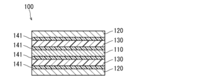
- a laminate 100 is formed as shown in FIGS. 1A and 1B.
- FIG. 1A is a top view of the laminate 100.
- FIG. 1B is a cross-sectional view taken along line IB--IB of FIG. 1A.
- FIG. 1C is a partially enlarged view of the cross-sectional view of FIG. 1B.
- illustration of the conductive polymer layer is omitted in order to make the drawings easier to see.
- the laminate 100 includes an anode foil 110, a cathode foil 120, and a separator 130.
- a dielectric layer (not shown) is formed on the surface of anode foil 110 .
- Laminate 100 is formed by laminating anode foil 110 , cathode foil 120 and separator 130 such that separator 130 is arranged between anode foil 110 and cathode foil 120 .
- the laminate 100 is formed by laminating a substantially flat anode foil 110, a substantially flat cathode foil 120, and a substantially flat separator 130 along the lamination direction SD.
- the planar shapes of those members used in the first embodiment are rectangular.
- a conductive polymer layer 141 is formed on the dielectric layer (not shown) on the surface of the anode foil 110 and on the cathode foil 120 .
- a conductive polymer layer 141 is also formed in the voids inside the separator 130 and on the surface of the separator 130 .
- Conductive polymer layer 141 on the electrode foil is formed on the surface where anode foil 110 and cathode foil 120 face each other.
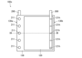
- FIGS. 2A to 2C A top view of the anode foil 110, a top view of the cathode foil 120, and a top view of the separator 130 are shown in FIGS. 2A to 2C.
- a plurality of first through holes 111 h are formed along one side of anode foil 110 .
- a plurality of second through holes 121 h are formed along one side of the cathode foil 120 .
- a plurality of third through holes 131 h are formed in the separator 130 along one side 130 a of the separator 130 .
- the separator 130 is formed with a plurality of fourth through holes 132h along another side 130b opposite to the side 130a.
- the through-hole of each member may be formed before laminating each member, or may be formed after laminating each member.
- the third through-hole 131h is formed at a position overlapping the first through-hole 111h when the laminate 100 is formed.
- 132 h of 4th through-holes are formed in the position which overlaps with 121 h of 2nd through-holes when the laminated body 100 is formed.
- the first through-hole 111h and the second through-hole 121h are arranged on a straight line in the first embodiment, they do not have to be arranged on a straight line.
- a conductive polymer layer is formed on the dielectric layer of the anode foil 110 , the cathode foil 120 and the separator 130 .
- the conductive polymer layer may be formed by a step of applying a dispersion containing a conductive polymer to a member (the member before constituting the laminate 100) and then drying it.
- the conductive polymer layer may be formed by a step of immersing at least a portion of the laminate (laminate 100 or laminate 100x) in a dispersion liquid containing a conductive polymer and then drying (for example, heat-treating).
- the conductive polymer layer may be formed by both of those steps.
- FIGS. 3A and 3B An example of the anode lead member 200 used in the connection process is shown in FIGS. 3A and 3B.
- FIG. 3A is a top view when viewed from the first protrusion 211 side
- FIG. 3B is a side view.
- Anode lead member 200 includes a rod-shaped anode connection portion 210 and a plurality of first protrusions 211 formed on anode connection portion 210 .
- An example protrusion 211 shown in FIGS. 3A and 3B has a conical shape.
- the shape of the cathode lead member 300 may be the same as that of the anode lead member 200 . As shown in FIGS.
- the cathode lead member 300 includes a bar-shaped cathode connection portion 310 and a plurality of second protrusions 311 formed on the cathode connection portion 310 .
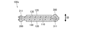
- FIG. 4A is a top view showing the stack 100x after the connecting step
- FIG. 4B is a cross-sectional view taken along line IVB-IVB in FIG. 4A.
- illustration of the conductive polymer layer is omitted in FIG. 4B, as shown in FIG. 1C, the laminate 100x includes the conductive polymer layer and functions as a capacitor element.
- the anode foil is electrically connected to the anode lead member by passing the plurality of first protrusions 211 through the plurality of first through holes 111h and the plurality of third through holes 131h and crimping (crushing). connect to.
- the cathode foil is electrically connected to the cathode lead member by passing the plurality of second projections 311 through the plurality of second through holes 121h and the plurality of fourth through holes 132h and crimping (crushing) them. do.
- the anode foil 110 is electrically connected to the anode lead member 200 by crimping the plurality of first protrusions 211 at positions where the cathode foil 120 is not laminated.
- the cathode foil 120 is electrically connected to the cathode lead member 300 by crimping the plurality of second projections 311 at positions where the anode foil 110 is not laminated. That is, the anode foil 110 and the separator 130 are fixed by the first projections 211 without the cathode foil 120 interposed therebetween, and the cathode foil 120 and the separator 130 are fixed by the projections 311 without the anode foil 110 interposed therebetween. According to these configurations, it is possible to suppress a short circuit between anode foil 110 and cathode foil 120 .
- the first convex portion 211 and the second convex portion 311 are passed through the laminate 100 from opposite directions. That is, in the example shown in Embodiment 1, the anode connection portion 210 and the cathode connection portion 310 are arranged in opposite directions with the laminate 100 interposed therebetween. However, they may be arranged on the same side of the laminate 100 . According to this configuration, the first protrusion 211 and the second protrusion 311 can be crimped from the same side.
- a conductive polymer layer is formed by performing an impregnation step and a removal step as necessary.
- the impregnation step at least part of the laminate 100x to which the lead members are connected is immersed in the liquid component (L), thereby impregnating the laminate 100x with the liquid component (L).
- the anode foil 110, the cathode foil 120, and the separator 130 may be loosely laminated by slightly pressing the first convex portion 211 and the second convex portion 311 once.
- the conductive polymer layer may be formed by performing an impregnation step and a removal step (for example, impregnating the laminate 100 with a conductive polymer dispersion and then drying). After that, the anode foil 110, the cathode foil 120, and the separator 130 may be fixed by firmly crimping the first convex portion 211 and the second convex portion 311.
- FIG. According to this method, the laminate 100 is easily impregnated with the dispersion liquid, so that it becomes easy to form the conductive polymer layer.
- the conductive polymer layer may be formed using a dispersion liquid after stacking the anode foil 110, the cathode foil 120, and the separator 130, without being formed during the stacking step (the step of FIG. 1A). .
- the laminated body 100x is enclosed in the exterior body 20.
- the impregnation step may be performed when the laminate 100 is enclosed in the exterior body 20, and the removal step may be performed after that.
- electrolytic capacitor 10 is manufactured.
- the periphery of the laminate 100x may be protected with an insulating material (insulating resin composition or insulating film) as necessary.
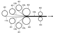
- the laminate 100 may be formed using the long anode foil 110L, the long cathode foil 120L, and the long separator 130L.
- FIG. 6 schematically shows an example of a method for forming the laminate 100 in that case.
- the long anode foil 110L, the long cathode foil 120L, and the long separator 130L are each wound around a roll 401.
- Anode foil 110L includes portions to be a plurality of anode foils 110
- cathode foil 120L includes portions to be a plurality of cathode foils 120L
- separator 130L includes portions to be a plurality of separators 130.
- FIG. 6 As shown in FIG. 6, they are sent out from rolls 401, gathered together by rolls 402, and laminated.
- the laminated body 100 can be formed by cutting the laminated long laminated body 100L into a predetermined length.
- the through-hole of each member may be formed before being wound on the roll.
- each member may be formed after they are delivered from the roll 401 and before they are laminated.
- the conductive polymer layer may be formed before being wound around the roll 401 or may be formed after being sent out from the roll 401 .
- At least one of the rolls 401, 402, and transport roll 403 may be a roll having a plurality of protrusions that fit into the through-holes arranged on the outer circumference. By using such rolls, alignment of each member can be facilitated.
- the formed laminate 100 is fixed with lead members as described above.
- the laminate 100 includes one anode foil 110 , but the laminate 100 may include a plurality of anode foils 110 .
Landscapes
- Engineering & Computer Science (AREA)
- Power Engineering (AREA)
- Microelectronics & Electronic Packaging (AREA)
- Fixed Capacitors And Capacitor Manufacturing Machines (AREA)
Priority Applications (1)
| Application Number | Priority Date | Filing Date | Title |
|---|---|---|---|
| JP2023569575A JPWO2023120708A1 (https=) | 2021-12-24 | 2022-12-23 |
Applications Claiming Priority (2)
| Application Number | Priority Date | Filing Date | Title |
|---|---|---|---|
| JP2021211334 | 2021-12-24 | ||
| JP2021-211334 | 2021-12-24 |
Publications (1)
| Publication Number | Publication Date |
|---|---|
| WO2023120708A1 true WO2023120708A1 (ja) | 2023-06-29 |
Family
ID=86902812
Family Applications (1)
| Application Number | Title | Priority Date | Filing Date |
|---|---|---|---|
| PCT/JP2022/047666 Ceased WO2023120708A1 (ja) | 2021-12-24 | 2022-12-23 | 電解コンデンサおよび電解コンデンサの製造方法 |
Country Status (2)
| Country | Link |
|---|---|
| JP (1) | JPWO2023120708A1 (https=) |
| WO (1) | WO2023120708A1 (https=) |
Citations (6)
| Publication number | Priority date | Publication date | Assignee | Title |
|---|---|---|---|---|
| JPS4919253U (https=) * | 1972-05-19 | 1974-02-18 | ||
| JPS5874337U (ja) * | 1981-11-14 | 1983-05-19 | エルナ−株式会社 | 積層型電解コンデンサ |
| JPH05326339A (ja) * | 1992-05-21 | 1993-12-10 | Matsushita Electric Ind Co Ltd | 電解コンデンサおよびその製造方法 |
| JPH07283086A (ja) * | 1994-04-14 | 1995-10-27 | Matsushita Electric Ind Co Ltd | 電解コンデンサ及びその製造方法 |
| JPH09312187A (ja) * | 1996-05-22 | 1997-12-02 | Nec Niigata Ltd | Cpuソケット |
| JP2004171850A (ja) * | 2002-11-19 | 2004-06-17 | Matsushita Electric Ind Co Ltd | シート形電子部品モジュール |
-
2022
- 2022-12-23 JP JP2023569575A patent/JPWO2023120708A1/ja active Pending
- 2022-12-23 WO PCT/JP2022/047666 patent/WO2023120708A1/ja not_active Ceased
Patent Citations (6)
| Publication number | Priority date | Publication date | Assignee | Title |
|---|---|---|---|---|
| JPS4919253U (https=) * | 1972-05-19 | 1974-02-18 | ||
| JPS5874337U (ja) * | 1981-11-14 | 1983-05-19 | エルナ−株式会社 | 積層型電解コンデンサ |
| JPH05326339A (ja) * | 1992-05-21 | 1993-12-10 | Matsushita Electric Ind Co Ltd | 電解コンデンサおよびその製造方法 |
| JPH07283086A (ja) * | 1994-04-14 | 1995-10-27 | Matsushita Electric Ind Co Ltd | 電解コンデンサ及びその製造方法 |
| JPH09312187A (ja) * | 1996-05-22 | 1997-12-02 | Nec Niigata Ltd | Cpuソケット |
| JP2004171850A (ja) * | 2002-11-19 | 2004-06-17 | Matsushita Electric Ind Co Ltd | シート形電子部品モジュール |
Also Published As
| Publication number | Publication date |
|---|---|
| JPWO2023120708A1 (https=) | 2023-06-29 |
Similar Documents
| Publication | Publication Date | Title |
|---|---|---|
| US11348739B2 (en) | Electrolytic capacitor | |
| JP7607224B2 (ja) | 電解コンデンサ | |
| US20200321162A1 (en) | Electrolytic capacitor | |
| US20170053745A1 (en) | Electrolytic capacitor manufacturing method | |
| JP6803519B2 (ja) | 電解コンデンサの製造方法 | |
| WO2017163725A1 (ja) | 電解コンデンサおよびその製造方法 | |
| JP2017175091A (ja) | 電解コンデンサおよびその製造方法 | |
| WO2015198546A1 (ja) | 電解コンデンサの製造方法 | |
| WO2022181667A1 (ja) | 電解コンデンサの製造方法 | |
| JP6726886B2 (ja) | 電解コンデンサおよびその製造方法 | |
| WO2023120708A1 (ja) | 電解コンデンサおよび電解コンデンサの製造方法 | |
| US20250182976A1 (en) | Electrolytic capacitor and method for producing electrolytic capacitor | |
| US20250104926A1 (en) | Electrolytic capacitor and method for producing electrolytic capacitor | |
| WO2024181212A1 (ja) | 電解コンデンサおよび電解コンデンサの製造方法 | |
| WO2023120707A1 (ja) | 電解コンデンサの製造方法 | |
| US20250095923A1 (en) | Electrolytic capacitor and method for manufacturing electrolytic capacitor | |
| JP4799797B2 (ja) | 固体電解コンデンサ | |
| US20260038745A1 (en) | Dispersion for use in manufacturing electrolytic capacitor, electrolytic capacitor manufacturing method, and electrolytic capacitor | |
| US20250022664A1 (en) | Electrolytic capacitor-use electrode foil, electrolytic capacitor, and electrolytic capacitor manufacturing method | |
| WO2024024888A1 (ja) | 電解コンデンサおよび電解コンデンサの製造方法 | |
| WO2025164474A1 (ja) | 電解コンデンサおよび電解コンデンサの製造方法 | |
| WO2024143346A1 (ja) | 電解コンデンサおよび電解コンデンサの製造方法 | |
| WO2024143344A1 (ja) | 電解コンデンサおよびその製造方法 | |
| WO2022210513A1 (ja) | 電解コンデンサの製造方法 | |
| WO2025163997A1 (ja) | 電解コンデンサおよび電解コンデンサの製造方法 |
Legal Events
| Date | Code | Title | Description |
|---|---|---|---|
| 121 | Ep: the epo has been informed by wipo that ep was designated in this application |
Ref document number: 22911409 Country of ref document: EP Kind code of ref document: A1 |
|
| WWE | Wipo information: entry into national phase |
Ref document number: 2023569575 Country of ref document: JP |
|
| NENP | Non-entry into the national phase |
Ref country code: DE |
|
| 122 | Ep: pct application non-entry in european phase |
Ref document number: 22911409 Country of ref document: EP Kind code of ref document: A1 |