WO2023120183A1 - 農業機械 - Google Patents
農業機械 Download PDFInfo
- Publication number
- WO2023120183A1 WO2023120183A1 PCT/JP2022/045042 JP2022045042W WO2023120183A1 WO 2023120183 A1 WO2023120183 A1 WO 2023120183A1 JP 2022045042 W JP2022045042 W JP 2022045042W WO 2023120183 A1 WO2023120183 A1 WO 2023120183A1
- Authority
- WO
- WIPO (PCT)
- Prior art keywords
- row
- agricultural machine
- image
- area
- region
- Prior art date
Links
Images


Classifications
-
- A—HUMAN NECESSITIES
- A01—AGRICULTURE; FORESTRY; ANIMAL HUSBANDRY; HUNTING; TRAPPING; FISHING
- A01B—SOIL WORKING IN AGRICULTURE OR FORESTRY; PARTS, DETAILS, OR ACCESSORIES OF AGRICULTURAL MACHINES OR IMPLEMENTS, IN GENERAL
- A01B69/00—Steering of agricultural machines or implements; Guiding agricultural machines or implements on a desired track
-
- G—PHYSICS
- G06—COMPUTING; CALCULATING OR COUNTING
- G06T—IMAGE DATA PROCESSING OR GENERATION, IN GENERAL
- G06T7/00—Image analysis
-
- G—PHYSICS
- G06—COMPUTING; CALCULATING OR COUNTING
- G06T—IMAGE DATA PROCESSING OR GENERATION, IN GENERAL
- G06T7/00—Image analysis
- G06T7/90—Determination of colour characteristics
Definitions
- This disclosure relates to agricultural machinery.
- a vision guidance system is being developed that detects rows of crops (rows of crops) or ridges in a field using an imaging device such as a camera, and controls traveling of work vehicles along the rows of crops or ridges that have been detected. .
- Patent Document 1 discloses a working machine that travels along ridges in cultivated land where crops are planted on ridges formed in rows. Patent Document 1 describes generating a planar projective transformation image after binarizing an original image obtained by photographing a cultivated land obliquely from above with an in-vehicle camera.
- the image recognition system may not always be able to continuously detect the row area.
- the present disclosure provides an agricultural machine capable of solving such problems.
- an agricultural machine includes an image recognition system that detects row regions of at least one of crops and ridges provided on the ground of a field from an acquired image; and a control device for controlling the traveling device, the traveling device being capable of operating in a row tracing traveling mode for controlling the traveling device to travel along the row region detected by the image recognition system. and a control device, wherein, when the image recognition system detects a defective portion of the row region or the end of the field during operation in the row following traveling mode, the controller causes the vehicle to travel for a predetermined time or a predetermined distance. continue.
- a computer-readable storage medium may include both volatile and non-volatile storage media.
- a device may consist of a plurality of devices. When the device is composed of two or more devices, the two or more devices may be arranged in one device, or may be divided and arranged in two or more separate devices. .
- the automatic steering mode is set to Since it is not released suddenly, the driver is not panicked. As a result, the driver has enough time to perform the operation for switching to manual steering, and it becomes possible to smoothly perform operations such as running or stopping running by manual steering.
- FIG. 1 is a block diagram schematically showing a basic configuration example of an agricultural machine in the present disclosure
- FIG. 1 is a block diagram showing a configuration example of an image recognition system
- FIG. FIG. 4 is a diagram schematically showing an arrangement example of switches and the like provided around the steering wheel of the agricultural machine
- FIG. 11 is a perspective view showing another example of a display device
- FIG. 4 is a diagram schematically showing a display screen of an operating terminal that displays the operating state of agricultural machinery
- FIG. 10 is a diagram schematically showing a display screen of an operating terminal that displays another operating state of the agricultural machine
- FIG. 9 is a diagram schematically showing a display screen of an operating terminal that displays still another operating state of the agricultural machine
- FIG. 9 is a diagram schematically showing a display screen of an operating terminal that displays still another operating state of the agricultural machine;
- FIG. 9 is a diagram schematically showing a display screen of an operating terminal that displays still another operating state of the agricultural machine;
- FIG. 9 is a diagram schematically showing a display screen of an operating terminal that displays still another operating state of the agricultural machine;
- FIG. 2 is a diagram schematically showing how an imaging device attached to an agricultural machine captures an image of the ground;
- FIG. 4 is a perspective view schematically showing the relationship between a body coordinate system ⁇ b and a camera coordinate system ⁇ c fixed with respect to agricultural machinery, and a world coordinate system ⁇ w fixed with respect to the ground.
- FIG. 2 is a top view schematically showing a portion of a field in which a plurality of rows of crops are provided on the ground;
- 14 is a diagram schematically showing an example of an image acquired by the imaging device of the agricultural machine shown in FIG. 13;
- FIG. FIG. 4 is a top view schematically showing a state in which the position and orientation (angle in the yaw direction) of the agricultural machine are adjusted;
- FIG. 16 is a diagram showing an example of an image acquired by the imaging device of the agricultural machine in the state of FIG. 15;
- 1 is a block diagram schematically showing a configuration example of a processing device according to a first embodiment of the present disclosure;
- FIG. 20 is a histogram of the green excess index (ExG) in the image of FIG. 19;
- FIG. 4 is a diagram showing an example of a top-view image (bird's-eye view image) classified into first pixels (for example, crop pixels) and second pixels (background pixels);
- FIG. 20 is a histogram of the green excess index (ExG) in the image of FIG. 19;
- FIG. 4 is a diagram showing an example of a top-view image (bird's-eye view image) classified into first pixels (for example, crop pixels) and second pixels (background pixels);
- FIG. 10 is a diagram showing an enhanced image obtained
- FIG. 3 is a perspective view schematically showing the positional relationship between each of the camera coordinate system ⁇ c1 and the camera coordinate system ⁇ c2 and the reference plane Re.
- FIG. 5 is a schematic diagram showing an example in which the direction of the rows of crops and the direction of the scanning lines in the top view image are parallel; 24 is a diagram schematically showing an example of an integrated value histogram obtained for the top view image of FIG. 23;
- FIG. 5 is a schematic diagram showing an example in which the direction of the row of crops and the direction of the scanning line in the top view image intersect;
- FIG. 26 is a diagram schematically showing an example of an integrated value histogram obtained for the top view image of FIG.
- FIG. 25 is a flow chart illustrating an example algorithm for determining crop row edge lines by a processing device in an embodiment of the present disclosure
- FIG. 22 is a diagram showing an integrated value histogram obtained from the top view image of FIG. 21
- 4 is a block diagram showing processing executed by a processing device according to an embodiment of the present disclosure
- FIG. FIG. 10 is a schematic diagram showing an example of a top view image in which a part of the row of crops is missing.
- 31 is a diagram schematically showing an example of an integrated value histogram obtained for the top view image of FIG. 30;
- FIG. 10 is a diagram for explaining how a top view image is divided into a plurality of blocks;
- 33 is a diagram schematically showing the relationship between the position of the scanning line and the integrated value of the index value in each block of FIG. 32;
- FIG. FIG. 34 is a diagram showing an example of a crop row center in each block in FIG. 33 and an approximate line for the crop row center;
- FIG. 35 is a top view showing an example of edge lines of crop rows determined based on the approximation lines of FIG. 34; For explaining a method of dividing part or all of the top view image into a plurality of blocks and determining the position of the edge line for each of the plurality of blocks when the crop row includes a curved portion. It is a diagram.
- FIG. 38 is a diagram schematically showing the relationship between the position of a scanning line and the integrated value (histogram) of index values in each block in FIG. 37;
- FIG. FIG. 38 is a diagram showing an example of a crop row center in each block in FIG. 37 and an approximate line for the crop row center;
- FIG. 39 is a top view showing an example of edge lines of crop rows determined based on the approximate curve of FIG. 38;
- FIG. 4 is a perspective view schematically showing rows of ridges provided on the ground; It is a figure which shows the image acquired at the time t from the imaging device.
- FIG. 10 is a diagram schematically showing a correspondence relationship of feature points between an image acquired from an imaging device at time t and an image acquired at time t+1;
- FIG. 4 is a perspective view schematically showing movement of feature points on ridges and an intermediate area (work passage) appearing in an image acquired by an imaging device;
- FIG. 3 is a diagram schematically showing the relationship between the amount of movement (first amount of movement) of feature points projected onto an image plane and the amount of movement (second amount of movement) of feature points projected onto a reference plane;
- FIG. 7 is a block diagram showing processing executed by a processing device according to the second embodiment of the present disclosure;
- FIG. 4 is a diagram showing the relationship between the average height of feature points on a scanning line and the position of the scanning line;
- FIG. 12 is a diagram illustrating a basic configuration example of an image recognition system according to a third embodiment of the present disclosure;
- FIG. 1 is a block diagram schematically showing a basic configuration example of an agricultural machine in the present disclosure
- FIG. 4 is a top view schematically showing an imaging range on the ground of time-series images acquired by an imaging device of an agricultural machine
- FIG. 4 is a top view schematically showing an imaging range on the ground of time-series images acquired by an imaging device of an agricultural machine
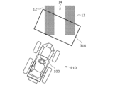
- FIG. 4 is a diagram schematically showing an example arrangement of rows of crops on the ground of a field and states at multiple positions of the agricultural machine during movement;
- FIG. 55 is a plan view schematically showing the positional relationship between the search area and the row of crops when the agricultural machine is at position P10 in FIG. 54;
- FIG. 55 is a diagram schematically showing the result of area classification of each block forming the search area when the agricultural machine is at position P10 in FIG. 54;
- FIG. 55 is a plan view schematically showing the positional relationship between the search area and the row of crops when the agricultural machine is at position P11 in FIG. 54;
- FIG. 55 is a diagram schematically showing the result of area classification of each block forming the search area when the agricultural machine is at position P11 in FIG. 54;
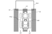
- FIG. 55 is a plan view schematically showing the positional relationship between the search area and the row of crops when the agricultural machine is at position P12 in FIG. 54;
- FIG. 55 is a diagram schematically showing the result of area classification of each block forming the search area when the agricultural machine is at position P12 in FIG. 54;
- FIG. 4 is a diagram showing an example of a search area of a top view image showing three rows of crops;
- FIG. 62 is a diagram schematically showing the relationship (histogram of integrated values) between the positions of scanning lines and the integrated values of index values obtained for each block in the search area in the top view image of FIG. 61;
- FIG. 63 is a diagram schematically showing an example of a two-dimensional block arrangement pattern formed by "row areas" detected in the search area of FIG.
- FIG. 10 is a diagram showing an example of a search area of a top-view image in which two rows of crops extending obliquely are captured
- FIG. 65 is a diagram schematically showing the relationship (histogram of integrated values) between the positions of scanning lines and the integrated values of index values obtained for each block in the search area in the top view image of FIG. 64
- FIG. 66 is a diagram schematically showing an example of a two-dimensional block arrangement pattern formed by "row areas" detected in the search area of FIG. 65
- 7 is a flow chart showing an example of a procedure for detecting a row region by a processing device
- 4 is a block diagram showing processing executed by a processing device according to an embodiment of the present disclosure
- FIG. 4 is a diagram showing blocks related to a path followed by wheels of an agricultural machine within a search area;
- FIG. 10 is a diagram showing another arrangement example of blocks within a search area;
- FIG. 10 is a diagram showing still another arrangement example of blocks within a search area;
- 1 is a perspective view showing an example of an appearance of an agricultural machine according to an embodiment of the present disclosure;
- FIG. 2 is a side view schematically showing an example of an agricultural machine with a work implement attached; It is a block diagram showing an example of a schematic structure of an agricultural machine and a working machine.
- Agricultural machinery in the present disclosure broadly includes machines that perform basic agricultural work such as “plowing”, “planting”, and “harvesting” in fields.
- Agricultural machines are machines having functions and structures for performing agricultural work such as tillage, sowing, pest control, fertilization, planting of crops, or harvesting on the ground in a field. These agricultural operations are sometimes referred to as “ground operations” or simply “operations.”
- ground operations or simply “operations.”
- a work vehicle such as a tractor functions alone as an “agricultural machine”
- the work machine (implement) attached to or towed by the work vehicle and the work vehicle as a whole can be regarded as one "agricultural machine”. It may work.
- Examples of agricultural machinery include tractors, riding machines, vegetable transplanters, mowers, and field mobile robots.
- FIG. 1 is a block diagram schematically showing a basic configuration example of an agricultural machine according to the present disclosure.
- the agricultural machine 100 in this example includes an image recognition system 1000 , a travel device 145 including steering wheels, and a control device 180 that controls the travel device 145 .
- the image recognition system 1000 comprises an imaging device 120, such as a camera mounted on the agricultural machine 100, for example, as shown in FIG. 2, and a processing device 122, which may be implemented by at least one computer.
- the image recognition system 1000 is configured to detect row regions of at least one of crops and ridges provided on the ground of a field from images acquired by the imaging device 120 . A method of detecting the row region by the image recognition system 1000 will be described later in detail.
- the agricultural machine 100 is capable of "following line running” in addition to running by normal manual steering.
- “Row following travel” means running by automatic steering along a row region detected by the image recognition system 1000 .
- the control device 180 controls the traveling device 145 to travel along the row area detected by the image recognition system 1000 .
- the orientation of the steered wheels during row following running is automatically controlled by, for example, a steering motor without the need for a person to operate the steering wheel.
- Such row following travel is performed by the control device so that the wheels of the traveling device (all wheels including the steering wheel) move through an area (working passage) between two adjacent row areas. 180 is executed to control the running gear 145 . Therefore, the image recognition system 1000 monitors the relationship between the position of the row area to be scanned (for example, the position of the "edge" of the row area) and the position of the wheel with high accuracy of several centimeters during row scanning. can do.
- wheel means “wheel with tire” or “wheel with endless track”.
- tire is used when referring to a tire portion of a wheel, for example, and the term “metal wheel” is used when referring to a metal “wheel” portion, for example.
- the image recognition system 1000 is configured not only to detect row regions in an image, but also to calculate the relative positions of the detected row regions with respect to the agricultural machine 100 with high accuracy.
- the position of the row area relative to the agricultural machine 100 is, for example, the coordinates of the row area in a local coordinate system fixed to the agricultural machine 100 .
- the row region coordinates do not need to be transformed into coordinates in the ground-fixed world coordinate system. Therefore, it is not necessary for the agricultural machine 100 during row-following travel to accurately measure its own position (for example, latitude and longitude) in the world coordinate system.
- the agricultural machine 100 is equipped with a self-position estimation device, the coordinates of the row region in the local coordinate system fixed to the agricultural machine 100 are converted into the coordinates in the world coordinate system fixed on the ground, and the row region Maps may be generated.
- the running speed of the agricultural machine 100 can be controlled according to the positions of operating members such as an accelerator pedal and a brake pedal operated by the driver (operator) during row following running.
- the travel speed of the agricultural machine 100 may also be automatically controlled by the controller 180 .
- the agricultural machine 100 in the present disclosure may be provided with a start switch 112 for commanding the start of row following travel. More specifically, the start switch 112 commands the start of row following travel in which the controller 180 controls the travel device 145 to travel along the row area detected by the image recognition system 1000 . Although the start switch 112 is connected to the control device 180 in the example of FIG. 1, it may be connected to the image recognition system 1000 as well.
- the start switch 112 can be provided around the driver's seat or around the steering wheel of the agricultural machine 100 .
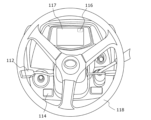
- FIG. 3 is a diagram schematically showing an arrangement example of switches and the like provided around the steering wheel 118 of the agricultural machine 100.
- the start switch 112 is, for example, a lever that can be switched up, down, forward, and backward from a neutral position.
- the start switch 112 is one of the members operated by the operator of the agricultural machine 100 .
- the agricultural machine 100 is provided with various switches operated by the driver.
- a driver of the agricultural machine 100 is hereinafter referred to as an "operator".
- the control device 180 in the present disclosure is configured to continue running for a predetermined time or a predetermined distance when the image recognition system 1000 detects a missing point in the row region or the end of the field while operating in the row following traveling mode.
- examples of the "missing part of the row region" include a part where the crop row is missing due to the crop dying, a part where the ridge is broken, and a crop row or ridge. contains parts that are partially covered by some object. Furthermore, not only cases in which a crop row or ridge is actually damaged, but also an area that could not be correctly detected as a row area due to erroneous recognition by the image recognition system 1000 is included in the "missing part of the row area.” .
- the start switch 112 is operated to issue a line tracing start command.
- the image recognition system 1000 determines whether or not the vehicle is in a state where row tracing traveling is possible, and row tracing traveling can be restarted in the automatic steering mode only when row tracing traveling is possible.
- the "predetermined time” of automatic steering running that continues after the image recognition system 1000 loses track of the row region can be set, for example, within the range of 1 second or more and 5 seconds or less.
- the “predetermined distance” can be set from, for example, a range of 1 meter or more and 5 meters or less, or the length of the agricultural machine 100 .
- These “predetermined time” and “predetermined distance” may be determined by the control device 180 to different values according to the travel speed of the agricultural machine 100 .
- the control device 180 may store a table or formula that defines the relationship between the "predetermined time” and/or the "predetermined distance” and the running speed in the storage device.
- the distance traveled by the agricultural machine 100 may be determined by the control device 180 based on, for example, the number of rotations of the wheels obtained from the traveling device 145, or may be determined using a positioning system such as GNSS, or self-position estimation technology. may decide.
- the running time of the agricultural machine 100 can be determined by measuring with a timer. Also, the distance traveled by the agricultural machine 100 may be determined by the controller 180 based on the product of travel speed and travel time.
- control device 180 preferably controls the travel device 145 so that it travels along the extension of the route traveled by the agricultural machine 100 . Control device 180 may stop after continuing such running.
- the control device 180 controls the image recognition system 1000 to detect a new row region while the image recognition system 1000 continues traveling for a predetermined time or a predetermined distance. If detected, it may be configured to control the carriage 145 to travel along the new row region.
- the control device 180 may determine the "predetermined time” or the "predetermined distance” according to the working machine.
- the "predetermined distance” is based on the sum of the length of the agricultural machine 100 and the length of the working machine. It may be the distance that the work implement passes through the end of the farm field.
- the "predetermined time” may be the time for the work machine to pass through the defective portion of the row region or the end of the field, taking into consideration the work speed and the length of the work machine according to the type of the work machine.
- the distance and the time required for the work machine to pass the adjacent previous work end point are “predetermined distance”, “predetermined distance”, “predetermined distance”, and “predetermined You can set the time.
- the agricultural machine 100 may include notification means for notifying the operator of a stop advance notice when the image recognition system 1000 detects the end of the field.
- notification means include display devices that display icons, letters or symbols, light emitting devices such as LEDs, and acoustic devices that emit sounds or vibrations such as buzzers or speakers.
- a voice message such as "currently line tracing is not possible" is output.
- a sound device may emanate, or characters may be displayed on a display device.
- the display device 117 positioned around the steering wheel 118 may display a symbol indicating whether or not "following the line" is possible as a notification 116.
- a notification 116 may be displayed on the display device 117 indicating that the agricultural machine 100 is approaching the end of the field.
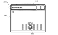
- FIG. 4 is a perspective view showing another example of the display device 117.
- the display device 117 may include an operation terminal 200 arranged around the driver's seat. On the display device 117 of the operation terminal 200, for example, as shown in FIG. 5, a notification 116 such as characters, symbols, etc. indicating that the end of the field is approaching can be displayed.
- the column areas displayed on the display device 117 are schematically illustrated as hatched bar-shaped areas.
- FIG. 6 shows an example of the display of the notification 116 that foretells that the agricultural machine 100 has reached the end of the field and will soon stop.
- FIG. 7 shows a display example of the notification 116 indicating that the agricultural machine 100 has passed the end of the field and stopped.
- This notification 116 may include information indicating that automatic steering has been switched to manual steering during row following running.
- FIG. 8 shows a display of a notice 116 that foretells that the image recognition system 1000 detects a defective portion of the row region during row-following running in the field, and that the vehicle automatically stops after running for a predetermined time or a predetermined distance. shows an example of
- FIG. 9 is an example of a display of a notification 116 indicating that the image recognition system 1000 has detected a defect in a row region during row tracing traveling in a field, but the row tracing traveling is to be continued by automatic steering without stopping. is shown.
- the image recognition system 1000 recognizes the position of the agricultural machine 100. It is desirable to determine whether or not the vehicle is in a state in which it is possible to follow the line on the basis of the positions of the wheels. When the image recognition system 1000 determines that it is not in a state in which line-following running is possible, a notification 116 indicating this may be displayed on the display device 117 .
- FIG. 10 shows an example of the notification 116 displayed on the display device 117 when the image recognition system 1000 determines that it is not possible to follow the line.
- the control device 180 is configured to execute the row following travel mode when the image recognition system 1000 detects a row area and also detects a work passage area having a predetermined width or more on both sides or one side of the row area. may have been
- the controller 180 determines whether the steered wheels can pass through the workpath area based on the workpath area and the position of the steered wheels, and if it determines that the steered wheels cannot pass the workpath area, the controller 180 determines that the workpath area cannot be passed. It can be configured to stop the contouring mode.
- the agricultural machine 100 may include a mode switch 114 for switching between automatic steering mode and manual steering mode, as shown in FIGS.
- the control device 180 can allow the start switch 112 to start following line running.
- the mode switch 114 for example, the steering motor can be energized for automatic steering.
- the image recognition system 1000 may also be configured to start image recognition processing for detecting row regions when the automatic steering mode is selected by the mode switch 114 .
- image recognition system 1000 When image recognition system 1000 starts image recognition processing in response to selection of the automatic steering mode by mode switch 114, image recognition system 1000 is configured to perform image processing in multiple stages. may be
- the mode switch 114 is provided around the steering wheel 118.
- mode switch 114 is a push button.
- the mode switch 114 is switched from an OFF state to an ON state, for example, when switching from the manual steering mode to the automatic steering mode. Conversely, when switching from the automatic steering mode to the manual steering mode, the ON state is switched to the OFF state.
- mode switch 114 is a switch that defines the start and end of the automatic steering mode.
- the start of the automatic steering mode does not mean that the automatic steering immediately starts following the line.
- control device 180 starts the line. Tracing running is started.
- row tracing traveling is started when the operator switches the start switch 112 downward from the neutral position, for example. Further, when the operator switches the start switch 112 upward from the neutral position, for example, during row tracing traveling, the signal output from the start switch 112 for instructing the start of row tracing traveling is stopped, or , the start switch 112 can output a signal instructing the train to stop running.
- the start switch 112 is a switch that turns on the row tracing running function of the agricultural machine 100.
- the control device 180 according to the present disclosure can operate even if there is an instruction to start row tracing running from the start switch 112. , may be configured so as not to immediately start line tracking.
- the image recognition system 1000 determines whether or not line-following traveling is possible, and that the command from the start switch 112 is valid only when it is determined that line-following traveling is possible. This processing and operation prevents row following running from starting when row following running is not possible, and makes it possible to avoid a situation where wheels trample a crop row or ridge.
- the traveling speed of the agricultural machine 100 can be controlled during row-following traveling according to the positions of operating members such as an accelerator pedal and a brake pedal operated by the operator.
- the travel speed of the agricultural machine 100 may also be automatically controlled by the controller 180 .
- FIG. 1 An embodiment of the image recognition system 1000 shown in FIG. 1 will be described below. Subsequently, embodiments of the agricultural machine 100 according to the present disclosure will be described in detail.
- the image recognition system 1000 in this embodiment includes an imaging device 120 attached to the agricultural machine 100 (FIG. 2).
- An imaging device 120 is fixed to the agricultural machine 100 to acquire time-series color images including at least a portion of the ground.
- FIG. 11 schematically shows how an imaging device 120 attached to an agricultural machine 100 such as a tractor or a riding management machine captures an image of the ground 10 .
- the agricultural machine 100 includes a vehicle body 110 that can travel, and an imaging device 120 is fixed to the vehicle body 110 .
- FIG. 11 shows a body coordinate system ⁇ b having mutually orthogonal Xb, Yb, and Zb axes.
- the body coordinate system ⁇ b is a coordinate system fixed to the agricultural machine 100, and the origin of the body coordinate system ⁇ b can be set near the center of gravity of the agricultural machine 100, for example. In the drawing, for ease of viewing, the origin of the body coordinate system ⁇ b is shown as being positioned outside the agricultural machine 100 .
- the Xb axis coincides with the traveling direction (the direction of arrow F) when the agricultural machine 100 travels straight.
- the Yb axis coincides with the rightward direction when the positive direction of the Xb axis is viewed from the coordinate origin, and the Zb axis coincides with the vertically downward direction.
- the imaging device 120 is, for example, an in-vehicle camera having a CCD (Charge Coupled Device) or CMOS (Complementary Metal Oxide Semiconductor) image sensor.
- the imaging device 120 in this embodiment is, for example, a monocular camera capable of capturing moving images at a frame rate of 3 frames per second (fps) or higher.
- FIG. 12 is a perspective view schematically showing the relationship between the body coordinate system ⁇ b, the camera coordinate system ⁇ c of the imaging device 120, and the world coordinate system ⁇ w fixed to the ground 10 described above.
- the camera coordinate system ⁇ c has mutually orthogonal Xc, Yc, and Zc axes
- the world coordinate system ⁇ w has mutually orthogonal Xw, Yw, and Zw axes.
- the Xw-axis and Yw-axis of the world coordinate system ⁇ w are on the reference plane Re extending along the ground 10 .
- the imaging device 120 is attached to a predetermined position of the agricultural machine 100 so as to face a predetermined direction. Therefore, the position and orientation of the camera coordinate system ⁇ c with respect to the body coordinate system ⁇ b are fixed in a known state.
- the Zc axis of the camera coordinate system ⁇ c is on the camera optical axis ⁇ 1.
- the camera optical axis ⁇ 1 is inclined from the traveling direction F of the agricultural machine 100 toward the ground 10, and the depression angle ⁇ is greater than 0°.
- a travel direction F of the agricultural machine 100 is generally parallel to the ground 10 on which the agricultural machine 100 travels.
- the depression angle ⁇ can be set, for example, within a range of 0° or more and 60° or less. When the position where the imaging device 120 is attached is close to the ground 10, the angle of depression ⁇ may be set to a negative value, in other words, the orientation of the camera optical axis ⁇ 1 may be set to have a positive elevation angle.
- the body coordinate system ⁇ b and the camera coordinate system ⁇ c translate with respect to the world coordinate system ⁇ w.
- the body coordinate system ⁇ b and the camera coordinate system ⁇ c may rotate with respect to the world coordinate system ⁇ w.
- the agricultural machine 100 does not rotate in the pitch and roll directions and moves substantially parallel to the ground 10 .
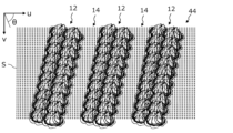
- FIG. 13 is a top view schematically showing part of a farm field in which a plurality of rows of crops 12 are provided on the ground 10.
- the crop row 12 is a row formed by continuously planting crops in one direction on the ground 10 of a field.
- a crop row 12 is a collection of crops planted on a ridge of a field.
- the shape of the crop row is complicated depending on the shape of the crops and the arrangement of the crops. be.
- the width of the crop row 12 varies as the crop grows.
- Each intermediate region 14 is a region sandwiched between two opposing edge lines E between two adjacent crop rows 12 .
- a plurality of crops are planted on one ridge in the width direction of the ridge, a plurality of rows of crops 12 are formed on one ridge. That is, a plurality of crop rows 12 are formed between rows of ridges.
- the edge line E of the row of crops 12 positioned at the edge in the width direction of the ridge serves as the reference for the intermediate region 14 . That is, the intermediate region 14 is located between the edge lines E of the row of crops 12 positioned at the edge in the width direction of the ridge among the edge lines E of the row of crops 12 .
- the intermediate area 14 functions as an area (work passage) through which the wheels of the agricultural machine 100 pass, the "intermediate area” may be referred to as a "work passage”.
- the "edge line" of a row of crops means a reference line segment (which may include a curved line) for defining a target route when the agricultural machine follows the row by automatic steering.
- Such reference line segments can be defined as the ends of a strip-shaped area (working path) through which the wheels of the agricultural machine are allowed to pass.
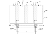
- FIG. 13 schematically shows one agricultural machine 100 entering a field in which a row of crops 12 is provided.
- the agricultural machine 100 includes left and right front wheels (steering wheels) 104F and left and right rear wheels 104R as traveling devices 145 to pull a working machine (implement) 300 .
- the front wheels 104F are steering wheels.
- the work passages 14 located on both sides of one row of crops 12 located in the center are marked with thick dashed arrows L and R, respectively.
- the front wheels 104F and the rear wheels 104R of the agricultural machine 100 move along the arrows L and R in the working path 14 so as not to step on the crop row 12.
- the image recognition system 1000 can detect the edge line E of the crop row 12 using the imaging device 120 attached to the agricultural machine 100. Therefore, the control device 180 and the travel device 145 operate to operate the front wheels (steering wheels).
- the agricultural machine 100 can travel in an automatic steering mode for row following traveling and a normal manual steering mode.
- Agricultural machine 100 may include a mode switch 114 shown in FIGS. 1 and 3 for the operator to switch between automatic steering mode and manual steering mode. The operator operates the mode switch 114 to select the automatic steering mode when the vehicle follows the line.
- the mode switch 114 selects the automatic steering mode, the image recognition system 1000 starts image recognition processing based on the image captured by the imaging device 120 .
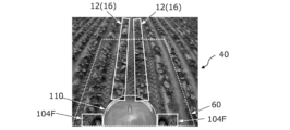
- FIG. 14 is a diagram schematically showing an example of the image 40 acquired by the imaging device 120 of the agricultural machine 100 shown in FIG.
- a plurality of rows of crops 12 and an intermediate area (working path) 14 running parallel on the ground 10 theoretically meet at a vanishing point P 0 on the horizon 11 .
- the vanishing point P0 is located in the right region of the image 40 because, as shown in FIG. This is because it is inclined with respect to
- the automatic steering will cause the front wheels 104F and the rear wheels 104R of the agricultural machine 100 to move in the working path 14. along the arrows L, R may not be possible.
- the image recognition system 1000 determines whether or not row tracing traveling is possible based on the position and direction of the steering wheels (front wheels 104F). If the image recognition system 1000 determines that line following travel is not possible, the operator is notified of this fact. The operator adjusts the position and/or orientation of the agricultural machine 100 by manual steering in response to the notification.
- FIG. 15 is a top view schematically showing a state in which the position and orientation (angle in the yaw direction) of the agricultural machine 100 are adjusted by steering the agricultural machine 100 so as to reduce the positional error with respect to the target path (arrow C).
- FIG. 16 is a diagram showing an example of an image 40 acquired by the imaging device 120 of the agricultural machine 100 in such a state.
- the front wheels 104F and the rear wheels 104R of the agricultural machine 100 in the state of FIG. 15 are positioned on the lines indicated by the arrows L and R in the work passage 14, respectively.
- the operator manually steers the agricultural machine 100 to change to, for example, the state shown in FIG. 15, the image recognition system 1000 determines that line-following travel is possible. , the operator may be notified thereof. In this embodiment, after the notification, the image recognition system 1000 stops immediately until the operator instructs the start of line tracking by using the start switch 112 in FIG. 3 . In this state, when the operator operates the start switch 112 to issue a command to start row tracing traveling, the control device 180 permits the start of row tracing traveling by automatic steering.
- the rear wheels 104R respectively control the steering angle of the steered wheels so that they do not deviate from the working path 14.
- the image recognition system 1000 includes, as shown in FIG.
- the processing device 122 is connected to a control device 180 included in the agricultural machine 100 .
- the processing device 122 in FIG. 2 can be realized by an electronic control unit (ECU) for image recognition.
- the ECU is an in-vehicle computer.
- the processing device 122 is connected to the imaging device 120 by a serial signal line such as a wire harness so as to receive image data output by the imaging device 120 .
- a part of the image recognition processing executed by the processing device 122 may be executed inside the imaging device 120 (inside the camera module).
- FIG. 17 is a block diagram showing a hardware configuration example of the processing device 122.
- the processing device 122 includes a processor 20 , a ROM (Read Only Memory) 22 , a RAM (Random Access Memory) 24 , a communication device 26 and a storage device 28 . These components are interconnected via bus 30 .
- the processor 20 is a semiconductor integrated circuit and is also called a central processing unit (CPU) or a microprocessor.
- Processor 20 may include an image processing unit (GPU).
- the processor 20 sequentially executes a computer program describing a predetermined group of instructions stored in the ROM 22 to implement the processing required for column detection of the present disclosure.
- a part or all of the processor 20 may be an FPGA (Field Programmable Gate Array) equipped with a CPU, an ASIC (Application Specific Integrated Circuit), or an ASSP (Application Specific Standard Product).
- the communication device 26 is an interface for data communication between the processing device 122 and an external computer.
- the communication device 26 can perform wired communication such as CAN (Controller Area Network), or wireless communication conforming to the Bluetooth (registered trademark) standard and/or the Wi-Fi (registered trademark) standard.
- the storage device 28 can store data of an image acquired from the imaging device 120 or an image during processing.
- Examples of storage device 28 include a hard disk drive or non-volatile semiconductor memory.
- the hardware configuration of the processing device 122 is not limited to the above example. Some or all of processing device 122 need not be installed on agricultural machine 100 . By using the communication device 26, one or more computers located outside the agricultural machine 100 can function as part or all of the processing device 122. FIG. For example, a networked server computer may function as part or all of processing unit 122 . On the other hand, a computer mounted on agricultural machine 100 may perform all functions required of processing device 122 .
- such a processing device 122 acquires time-series color images from the imaging device 120 and performs operations S1, S2, and S3 described below.
- S1 Generate an enhanced image in which the color of the row of crops to be detected is enhanced from the time-series color images.
- S2 Generating a top view image of the ground viewed from above, in which the first pixels having the index value of the color of the row of crops equal to or larger than the threshold value and the second pixels having the index value smaller than the threshold value are classified from the enhanced image. do.
- S3 determining the position of the edge line of the crop row based on the index value of the first pixel;
- a time-series color image is a collection of images acquired by the imaging device 120 in a time-series manner. Each image is composed of a group of pixels in frame units. For example, if the imaging device 120 outputs images at a frame rate of 30 frames/second, the processing device 122 may acquire new images at intervals of approximately 33 milliseconds.
- the speed at which the agricultural machine 100 such as a tractor travels in a field is relatively low compared to the speed of general automobiles traveling on public roads, and can be, for example, about 10 kilometers per hour or less. At 10 kilometers per hour, the distance traveled in about 33 milliseconds is about 6 centimeters.
- the processing device 122 may acquire images at intervals of, for example, 100 to 300 milliseconds, and does not need to process all frame images captured by the imaging device 120 .
- the acquisition cycle of images to be processed by the processing device 122 may be automatically changed by the processing device 122 according to the travel speed of the agricultural machine 100 .
- FIG. 18 is an image corresponding to one frame of image 40 in time-series color images acquired by an imaging device (a monocular camera in this example) mounted on agricultural machinery.
- the image in FIG. 18 shows rows of crops (rows of crops) planted in rows on the ground of a field.
- rows of crops are arranged substantially parallel and evenly spaced on the ground, and the camera optical axis of the imaging device faces the direction of travel of the agricultural machine.
- the camera optical axis need not be parallel to the traveling direction of the agricultural machine, and may be incident on the ground ahead of the traveling direction of the agricultural machine.
- the mounting position of the imaging device is not limited to this example. When a plurality of imaging devices are attached to the agricultural machine, some of the imaging devices may face the camera optical axis in the direction opposite to the direction of travel or in the direction crossing the direction of travel.
- the processing device 122 in FIG. 2 generates an image (enhanced image) in which the color of the crop row to be detected is enhanced, based on the time-series color images acquired from the imaging device 120 .
- Crops have chlorophyll (chlorophyll) in order to receive sunlight (white light) and perform photosynthesis. Chlorophyll absorbs less green light than red and blue light. Therefore, the spectrum of sunlight reflected by crops exhibits relatively high values in the green wavelength range compared to the spectrum of sunlight reflected by the soil surface. As a result, crop color generally has a high green component and the "crop row color” is typically green. However, as will be described later, the "crop row color” is not limited to green.
- the image sensor in the imaging device 120 has a large number of photodetection cells arranged in rows and columns.
- Each photodetector cell corresponds to a picture element (pixel) that constitutes an image, and includes an R sub-pixel that detects the intensity of red light, a G sub-pixel that detects the intensity of green light, and an intensity of blue light. , including B sub-pixels for detecting .
- the output of light detected by the R subpixel, G subpixel, and B subpixel in each photodetector cell will be referred to as the R value, G value, and B value, respectively.
- the R value, G value, and B value may be collectively referred to as "pixel value" or "RGB value”.
- RGB value RGB value
- the enhanced image in which the color of the row of crops is emphasized means that the RGB value of each pixel in the color image acquired by the imaging device is set to a relatively large weight of the G value.
- This is an image converted into pixel values.
- Such conversion of pixel values for generating an enhanced image is defined, for example, as "(2 ⁇ G value ⁇ R value ⁇ B value)/(R value+G value+B value)".
- the denominator (R value+G value+B value) is a factor for normalization.
- rgb R value / (R value + G value + B value)
- g G value / (R value + G value + B value)
- b B value / (R value + G value + B value).
- ExG Excess Green Index
- FIG. 19 is a diagram showing an enhanced image 42 obtained by converting the RGB values in the image of FIG. 18 into "2 ⁇ grb".
- FIG. 19 pixels in which "r+b” is relatively small compared to g are displayed brightly, and pixels in which "r+b” is relatively large compared to g are displayed darkly.
- an image (enhanced image) 42 in which the color (in this example, "green") of the crop rows to be detected is enhanced is obtained.
- the brighter pixels in the image of FIG. 19 are pixels with a relatively large green component and belong to crop regions.
- NDVI Normalized Difference Vegetation Index
- each row of crop rows may be covered with a mulching sheet called "mulch".
- the "color of the crop row” is "the color of the objects arranged in a row over the crop”. Specifically, when the color of the sheet is black, which is an achromatic color, the "crop row color” means “black.” Also, if the color of the sheet is red, the “color of the crop row” means “red”. Thus, the "color of the crop row” means not only the color of the crop itself but also the color of the area defining the crop row (a color distinguishable from the color of the soil surface).
- the HSV color space is a color space composed of three components of hue (Hue), saturation (Saturation), and lightness (Value).
- hue Hue
- saturation saturation
- Value lightness
- the processing device 122 In operation S2, the processing device 122 generates a top view image classified from the enhanced image 42 into first pixels having a crop row color index value equal to or greater than a threshold and second pixels having an index value less than the threshold. do.
- a top view image is an image viewed from above the ground.
- FIG. 20 is a histogram of the green excess index (ExG) in the enhanced image 42 of FIG. The horizontal axis of the histogram is the green excess index (ExG), and the vertical axis is the number of pixels in the image (corresponding to the frequency of occurrence).
- FIG. 20 shows a dashed line indicating the threshold Th calculated by the discriminant analysis algorithm. Pixels of the enhanced image 42 are classified into two classes by this threshold Th.
- the occurrence frequency of pixels whose green excess index (ExG) is equal to or greater than the threshold is shown, and these pixels are estimated to belong to the crop class.
- the occurrence frequency of pixels whose green excess index (ExG) is less than the threshold is shown, and these pixels are considered to belong to the crop class such as soil. Presumed.
- the first pixel which is the pixel whose index value is greater than or equal to the threshold value, corresponds to the "crop pixel”.
- the second pixels whose index values are less than the threshold correspond to "background pixels".
- the background pixels correspond to objects other than the object to be detected, such as the surface of the soil, and the aforementioned intermediate region (working passage) 14 can be constituted by the background pixels.
- the threshold determination method is not limited to the above example, and the threshold may be determined using, for example, another method using machine learning.
- the detection target area can be extracted from the enhanced image 42. Further, by giving "zero” to the pixel value of the "second pixel” or removing the data of the second pixel from the image data, it is possible to mask the area other than the detection target. When determining the area to be masked, processing may be performed to include pixels with locally high values of the excess green index (ExG) as noise in the mask area.
- ExG excess green index
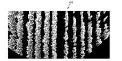
- FIG. 21 is a diagram showing an example of a top view image 44 seen from above the ground, classified into first pixels and second pixels.
- a top-view image 44 in FIG. 21 is an image created from the enhanced image 42 in FIG. 19 by an image conversion technique, which will be described later.
- the second pixels whose crop row color index value (in this example, the excess green index) is less than the threshold Th are black pixels (pixels whose lightness is set to zero).
- the area formed by the second pixels is mainly the area where the surface of the soil on the ground can be seen.
- black triangular areas exist at the left and right corners that are in contact with the lower side.
- This triangular area corresponds to the area that was not shown in the enhanced image 42 of FIG.
- a phenomenon is observed in which a line that should be straight is distorted in the peripheral portion of the image.
- image distortion is caused by the performance of the camera's lens and can be corrected using the camera's intrinsic parameters.
- Processing such as crop area enhancement, masking, and distortion correction can be referred to as preprocessing.
- Preprocessing may include processing other than such processing.
- a top-view image 44 in FIG. 21 is a bird's-eye view image of the reference plane Re parallel to the ground viewed from directly above in the normal direction of the reference plane Re.
- This bird's-eye view image can be generated from the enhanced image 42 of FIG. 19 by homography transformation (planar projective transformation).
- a homographic transformation is a type of geometric transformation that can transform a point on one plane in three-dimensional space to a point on any other plane.
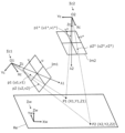
- FIG. 22 shows the positional relationship between the camera coordinate system ⁇ c1 of the imaging device in the first orientation (position and orientation: pose) and the camera coordinate system ⁇ c2 of the imaging device in the second orientation, and the reference plane Re.
- the camera coordinate system ⁇ c1 is tilted so that its Zc axis obliquely intersects the reference plane Re.
- the imaging device in the first posture corresponds to the imaging device attached to the agricultural machine.
- the Zc axis of the camera coordinate system ⁇ c2 is orthogonal to the reference plane Re.
- the camera coordinate system ⁇ c2 is arranged such that the reference plane Re can be obtained as a bird's-eye view image viewed from directly above in the normal direction of the reference plane Re.
- a virtual image plane Im1 exists at a position separated by the focal length of the camera on the Zc axis from the origin O1 of the camera coordinate system ⁇ c1.
- the image plane Im1 is orthogonal to the Zc axis and the camera optical axis ⁇ 1.
- a pixel position on the image plane Im1 is defined by an image coordinate system having mutually orthogonal u and v axes.
- the coordinates of points P1 and P2 located on the reference plane Re are (X1, Y1, Z1) and (X2, Y2, Z2), respectively, in the world coordinate system ⁇ w.
- the reference plane Re is set so as to extend along the ground.
- Points P1 and P2 on the reference plane Re are transformed into points p1 and p2 on the image plane Im1 of the imaging device in the first posture, respectively, by perspective projection of the pinhole camera model.
- points p1 and p2 are located at pixel locations indicated by coordinates (u1, v1) and (u2, v2), respectively.
- a virtual image plane Im2 exists at a position separated by the focal length of the camera on the Zc axis from the origin O2 of the camera coordinate system ⁇ c2.
- the image plane Im2 is parallel to the reference plane Re.
- a pixel position on the image plane Im2 is defined by an image coordinate system having mutually orthogonal u * and v * axes.
- Points P1 and P2 on the reference plane Re are transformed into points p1 * and p2 * , respectively, on the image plane Im2 by perspective projection.
- points p1 * and p2 * are located at pixel locations indicated by coordinates (u1 * , v1 * ) and (u2 * , v2 * ), respectively.
- homography Given the positional relationship of the camera coordinate systems ⁇ c1 and ⁇ c2 with respect to the reference plane Re (world coordinate system ⁇ w), homography transforms an arbitrary point (u, v) on the image plane Im1 to correspond on the image plane Im2. We can find the point (u * , v * ) where Such a homography transformation is defined by a transformation matrix H of 3 rows ⁇ 3 columns when coordinates of points are expressed in a homogeneous coordinate system.
- the contents of the transformation matrix H are defined by the numerical values of h 11 , h 12 , . . . , h 32 as shown below.
- the contents of the transformation matrices H1 and H2 depend on the reference plane Re, so when the position of the reference plane Re changes, the contents of the transformation matrix H also change.
- the homography transformation By using such a homography transformation, it is possible to generate a top view image of the ground from the image of the ground acquired by the imaging device in the first posture (the imaging device attached to the agricultural machine).
- the coordinates of an arbitrary point on the image plane Im1 of the imaging device 120 are converted to the image plane Im2 of a virtual imaging device in a predetermined orientation with respect to the reference plane Re. Can be converted to point coordinates.
- the processing device 122 executes a software program based on the above algorithm to obtain a view of the ground 10 from above from the time-series color images or the preprocessed images of the time-series color images. generates a bird's-eye view image.
- the ground 10 may have irregularities such as ridges, ridges, and grooves. In such cases, the reference plane Re may be displaced upwards from the bottom of such irregularities. The displacement distance can be appropriately set according to the unevenness of the ground 10 on which the crops are planted.
- the attitude of the imaging device 120 changes, so the content of the conversion matrix H1 changes. can.
- the rotation angles of roll and pitch of the vehicle body 110 are measured by the IMU, the transformation matrix H1 and the transformation matrix H can be corrected according to the posture change of the imaging device.
- the processing device 122 in this embodiment classifies the first pixels having the index value of the color of the row of crops above the threshold value and the second pixels having the index value less than the threshold value from above the ground by the above-described method. After generating the seen top view image, operation S3 is performed.
- the processing unit 122 determines the position of the edge line of the crop row based on the index value of the first pixel. Specifically, the index values of the first pixels (pixels whose color index value is equal to or greater than a threshold value) are integrated along a plurality of scanning lines in the top view image.
- FIG. 23 is an example of a top view image 44 in which three crop rows 12 are shown.
- the crop row 12 direction is parallel to the image vertical direction (v-axis direction).
- FIG. 23 shows a large number of scanning lines (broken lines) S parallel to the image vertical direction (v-axis direction).
- the processing device 122 integrates index values of pixels located on a plurality of scanning lines S for each scanning line S to obtain an integrated value.
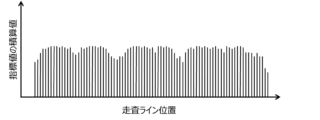
- FIG. 24 is a diagram schematically showing the relationship (histogram of integrated values) between the positions of the scanning lines S and the integrated values of the index values obtained for the top view image of FIG.
- the horizontal axis of FIG. 24 indicates the position of the scanning line S in the image horizontal direction (u-axis direction).
- the integrated value of the scanning line S is large.
- the second pixels (background pixels) belonging to the intermediate area (work path) 14 between the crop rows 12 the integrated value for that scan line S will be small. Note that in this embodiment the intermediate region (working path) 14 is masked and the index value for the second pixel is zero.
- the position of the edge line of each row of crops 12 is the position of the scanning line S having a value that is 80% of the peak of the integrated value of each row of crops 12 .
- the index values of the color of the crop row on each scanning line S are integrated. That is, the number of first pixels (the number of pixels) is not counted for the binarized top view image based on the classification of the first pixels and the second pixels.
- the count value of the first pixel is increases.
- accumulating the index value of the color of the crop row of the first pixels instead of the number of the first pixels suppresses erroneous determination due to fallen leaves and weeds. , to increase the robustness of column detection.
- FIG. 25 is an example of a top view image 44 in which the crop row 12 extends obliquely.
- the direction in which the crop row 12 extends in the image 40 acquired by the imaging device 120 may be slanted to the right or left in the image.
- the direction of the crop row 12 is inclined from the image vertical direction (v-axis direction) as in the example of FIG.
- FIG. 25 also shows a large number of scanning lines (broken lines) S parallel to the image vertical direction (v-axis direction).
- the processor 122 integrates the index values of the pixels positioned on the plurality of scanning lines S for each scanning line S to obtain an integrated value
- a histogram of integrated values as shown in FIG. 26 is obtained.
- FIG. 26 is a diagram schematically showing the relationship between the position of the scanning line S and the integrated value of the index values obtained for the top view image of FIG. From this histogram the edge lines of the crop row 12 cannot be determined.
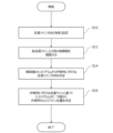
- FIG. 27 is a flowchart showing an example of a procedure for searching for the direction (angle) of the scanning line S parallel to the direction of the crop row 12 by changing the direction (angle) of the scanning line S.
- step S10 the direction (angle) of the scanning line S is set.
- the clockwise angle is ⁇ with respect to the u-axis in the image coordinate system (see FIGS. 23 and 25).
- the search for the angle ⁇ can be set to a range of, for example, 60 to 120 degrees and an angle step of, for example, 1 degree.
- the angle ⁇ of the scanning line S is given as 60, 61, 62, .
- step S12 index values are integrated for pixels on the scanning line S extending in the direction of each angle ⁇ , and a histogram of integrated values is created. The histogram will show different distributions depending on the angle ⁇ .
- step S14 from the plurality of histograms obtained in this way, a histogram is selected that has a sharp boundary between unevenness as shown in FIG. Find the angle ⁇ of the scan line S that produces .
- step S16 the edge line of each crop row 12 is determined from the peak value of the histogram corresponding to the angle ⁇ obtained in step S14.
- the position of the scan line S having an integrated value of, for example, 0.8 times the peak can be taken as the edge line.
- a histogram of integrated values of the angle ⁇ on the scanning line S may be created.
- a characteristic quantity for example, depth of recess/height of convex portion, envelope differential value, etc. is calculated from the waveform of the histogram, and the direction of the crop row 12 and the direction of the scanning line S are determined based on the characteristic quantity. are parallel or not.
- the method for obtaining the angle ⁇ is not limited to the above example. If the direction in which the crop row extends is known by measurement, the orientation of the agricultural machine may be measured by an inertial measurement unit (IMU) mounted on the agricultural machine 100 to determine the angle ⁇ with respect to the direction in which the crop row extends.
- IMU inertial measurement unit
- FIG. 28 is a diagram showing an example of an integrated value histogram created from the top view image of FIG.
- the position of the edge line E is the position of the scanning line that is 0.8 times the peak value of the convex portion of the histogram located in the center.
- the peak of the convex portion becomes lower and the peak of the convex portion spreads.
- the distortion of the image is small at the center of the top view image, but the distortion of the image increases as the distance from the center to the left and right increases. This is due to the black triangular areas located on both sides of the lowering the integrated value.
- the crop row that should be accurately detected is the center or periphery of the image. Therefore, distortion in regions near the left and right ends of the top view image can be ignored.
- FIG. 29 is a block diagram showing a series of processes executed by the processing device 122 in this embodiment.
- the processor 122 performs image acquisition 32, enhanced image generation 33, crop row extraction 34, and homography transformation 35 to generate a top view image 44 such as that shown in FIG. Obtainable.
- Processing unit 122 may also perform scanline orientation determination 36 and edgeline location determination 37 to obtain the location of the edgelines of the crop row.
- the processing device 122 or the path generation device that obtains the information indicating the position of the edge line from the processing device 122 can perform the target path generation 38 of the agricultural machine based on the edge line.
- the target path can be generated in such a way that the wheels of the agricultural machine are kept in the intermediate area (workpath) 14 between the edge lines E.
- the target path can be generated such that the widthwise central portion of the tire mounted on the metal wheel passes through the center of two edge lines located at both ends of the intermediate region (working passage) 14 .
- the target route even if the agricultural machine deviates from the target route by several centimeters during travel, it is possible to reduce the possibility that the tires will enter the crop row.
- the embodiments of the present disclosure it is possible to suppress the effects of weather conditions such as front light, backlight, fine weather, cloudy weather, and fog, and sunlight conditions that change depending on the working hours, and to detect crop rows with high accuracy. It was confirmed.
- the crop type cabbage, broccoli, radish, carrot, lettuce, Chinese cabbage, etc.
- growth state from seedling to mature state
- presence of disease presence of fallen leaves/weeds
- robustness even when soil color changes
- the homography transformation is performed after the step of obtaining the threshold value for binarization and extracting the crop area using pixels equal to or higher than the threshold value.
- the step of extracting crop regions may be performed after the homography transformation.
- homography transformation 35 may be performed between enhanced image generation 33 and crop row extraction 34, or between image acquisition 32 and enhanced image generation 33. may be performed between
- the image recognition system 1000 of this embodiment even if part of the crop row is lost at a defect location, the extension line of the target route generated from the edge line used for the row following travel up to that point is obtained, and the extension line is obtained. as the target route. Therefore, the agricultural machine 100 can temporarily travel along the extension line. Further, after the image recognition system 1000 detects the “missing point” or the “end of the field” in the row of crops, the integrated value of the pixel values increases while the running continues, and the integrated value histogram shows a convex area. When it appears, the target path is generated with this convex area as the row area of the new crop row.
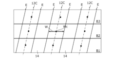
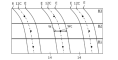
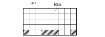
- FIG. 32 is a diagram for explaining a method of dividing part or all of the top view image into a plurality of blocks and determining the position of the edge line for each of the plurality of blocks.
- the processing device 122 divides part or all of the top view image 44 into a plurality of blocks. Then, the position of the edge line E of the crop row 12 is determined for each of the plurality of blocks. In the illustrated example, three blocks B1, B2, and B3 have a belt shape continuous in the horizontal direction of the image in the top view image. The processing device 122 can determine the edge line of the crop row based on the band shape in a direction different from the traveling direction of the agricultural machine 100 .
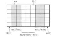
- FIG. 33 is a diagram schematically showing the relationship (integrated value histogram) between the position of the scanning line S and the integrated index value in each of the blocks B1, B2, and B3 of the top view image in FIG.
- the scanning line S when performing integration is always parallel to the image vertical direction.
- the index values are integrated block by block, and the direction (angle) of the scanning line S does not need to be changed.
- Both ends of the arrow W in FIG. 33 indicate the positions of the edge lines of the rows of crops determined in each of the blocks B1, B2, and B3.
- the crop row 12 direction is slanted with respect to the scan line S direction. Therefore, as described above, when a scanning line position showing a value 0.8 times the peak value of the integrated value histogram is adopted as the position of the edge line E of the crop row 12, such an edge line E corresponds to both ends of the "width" passing near the center of the crop row 12 in each of the blocks B1, B2, and B3.
- FIG. 34 shows the crop row center Wc in each of blocks B1, B2, and B3 in FIG.
- the crop row center Wc is obtained from the center of the arrow W that defines the edge line of the crop row obtained from the integrated value histogram of FIG. 33, and is located at the center of each block in the image vertical direction.
- FIG. 34 shows an example of the approximation line 12C for the crop row center Wc belonging to the same crop row 12.
- the approximation line 12C is, for example, a straight line obtained so as to minimize the root mean square distance (error) from the plurality of crop row centers Wc of each crop row 12 .
- Such an approximation line 12C corresponds to a line passing through the center of the crop row 12.
- FIG. 34 shows the crop row center Wc in each of blocks B1, B2, and B3 in FIG.
- the crop row center Wc is obtained from the center of the arrow W that defines the edge line of the crop row obtained from the integrated value histogram of FIG. 33, and is located
- FIG. 35 is a top view showing an example of the edge line E of the row of crops 12 determined from the approximation line 12C of FIG.
- the two edge lines E associated with each crop row 12 are spaced equal to the length of the arrow W and equidistant from the approximation line 12C.
- the edge line E of the crop row 12 can be obtained with a smaller amount of calculation without changing the direction (angle) of the scanning line.
- the length of each block in the image vertical direction can be set to correspond to a distance of 1 to 2 meters on the ground, for example.
- one image is divided into three blocks to obtain the integrated value histogram, but the number of blocks may be four or more.
- the shape of the block is not limited to the above example.
- a block can have a strip shape that is continuous in either the horizontal direction of the image or the vertical direction of the image in the top view image.
- the processing device 122 can divide the crop into strip-shaped blocks extending in a direction different from the traveling direction of the agricultural machine 100 and determine the edge line of the row of crops.
- FIG. 36 schematically shows how the crop row 12 of the top view image 44 includes a curved portion.
- FIG. 37 schematically shows integrated value histograms in each of the blocks B1, B2, and B3 of the top view image 44 of FIG.
- FIG. 38 is a diagram showing an example of the crop row center Wc in each of the blocks B1, B2, and B3 in FIG. 37 and the approximation line 12C for each crop row center Xc.
- the approximation line 12C in this example is, for example, a curve obtained so as to minimize the root mean square of the distance (error) of each crop row 12 from the crop row center Wc (for example, a higher-order curve such as a cubic curve). is.
- Such approximate line 12C corresponds to a curved line passing through the center of crop row 12 having curved portions.
- FIG. 39 is a top view showing an example of the edge line E of the row of crops 12 determined from the approximation line of FIG.
- Edge line E is generated in a manner similar to that described with reference to FIG. That is, the two edge lines E associated with each row of crops 12 are spaced equal to the length of the arrow W and equidistant from the approximation line 12C.
- the top view image is divided into a plurality of blocks and a histogram of integrated values is generated for each block, it becomes easier to determine the direction of the crop row, and the direction of the crop row can be easily obtained. Even if the direction changes on the way, it becomes possible to know the changed direction.
- Any of the above column detection methods can be implemented by being implemented in a computer and causing the computer to perform desired operations.
- the image recognition system 1000 can move along the crop row during temporary running until it stops. It becomes possible to maintain proper row-following running on a straight line or a curve.
- low position accuracy detection processing may be performed.
- This low positional accuracy detection process may be, for example, a process targeting some images selected from the time-series images acquired by the imaging device 120 .
- the number of scanning lines is increased, the length of each block in the vertical direction of the image is reduced, or the number of blocks is increased, thereby starting detection processing with improved positional accuracy. It is desirable to After the row area is detected and it is determined that row tracing traveling is possible, the operator issues a command to start row tracing traveling with the start switch 112, and then the detection processing with improved accuracy is started. good.
- the computational load of the processing device 122 can be effectively reduced.
- the above blocks can be set within a region (region of interest) selected from the image to determine row detection.
- image recognition system 1000 selects a region of interest to be subjected to image recognition processing, and performs processing to make the region of interest during row tracing traveling smaller than the region of interest before row following traveling. may Specifically, during row scanning, a relatively narrow range including the row region to be scanned may be selected as the region of interest.
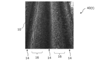
- FIG. 40 is a perspective view schematically showing rows of ridges 16 provided on the ground 10.
- FIG. "Ridge” is a place where plants are planted for streaking or streaking, and is a convex portion that extends in a substantially straight line, with soil piled high at intervals.
- the cross-sectional shape of the ridges 16, perpendicular to the direction in which the ridges 16 extend, can be generally trapezoidal, semicylindrical, or semicircular.
- a ridge 16 having a trapezoidal cross-section is schematically depicted. Real ridges do not have a simple shape as shown in FIG. Between two adjacent ridges 16 is an intermediate region 14, called a ridge.
- the intermediate area 14 functions as a working passageway.
- the ridges 16 may be planted with crops or may be unplanted, with only the soil exposed as a whole. Also, each of the ridges 16 may be covered with mulch.
- the height, width and spacing of the ridges 16 do not need to be uniform and may vary from place to place.
- the height of the ridges 16 is generally the difference in height between the ridges.
- the “height” of the ridges 16 is defined by the distance from the reference plane Re described above to the top surface of each ridge 16 .
- the edge lines of the ridges 16 are clear. However, since the actual ridge 16 is a part of the ground 10 that is continuous from the intermediate region 14, and the "cross-sectional shape" of the ridge 16 varies as described above, the boundary between the ridge 16 and the intermediate region 14 is Not always clear.
- the edge lines of the ridges 16, i.e., the boundaries between the ridges 16 and the intermediate regions 14, are located on both sides of the peak of each ridge 16 and have a height that is a predetermined percentage of the peak. defined as a position. The position of the edge line is, for example, 0.8 times the height of the peak of each ridge 16 .
- the image recognition system 1000 also includes an imaging device 120 and a processing device 122 that performs image processing on time-series color images acquired from the imaging device 120, as shown in FIG.
- the hardware configuration of the processing device 122 is the same as the configuration of the processing device 122 in the first embodiment.
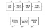
- the processing device 122 acquires time-series images from the imaging device 120 and performs operations S21, S22, and S23 described below.
- S21 From a plurality of images acquired at different times of the time-series images, a first movement amount within the image plane is obtained for each of the plurality of feature points by feature point matching.
- S22 Each of the plurality of feature points is perspectively projected from the image plane onto a reference plane corresponding to the ground, and a second movement amount of each projection point within the reference plane is obtained based on the first movement amount.
- S23 Based on the second amount of movement, the heights of the plurality of feature points from the reference plane are estimated to detect ridges on the ground.
- operation S21 will be described.
- operation S11 from a plurality of images acquired at different times of the time-series images, a first movement amount within the image plane is obtained for each of the plurality of feature points by feature point matching.
- a time-series image is a collection of images acquired in time-series by imaging by the imaging device 120 .
- the time-series images need not be color images, but may be color images.
- the processing device 122 may grayscale the color images to be processed of the time-series color images.
- each image is composed of pixel groups in units of frames.
- the frame rate is also the same as described in the first embodiment.
- FIG. 41 is an image 40(t) of one frame in time-series images acquired at time t by the imaging device (monocular camera in this example) 122 mounted on the agricultural machine 100 .
- the imaging device monocular camera in this example
- ridge 16 is not planted with crops. Depth information is not included in the data of the image 40(t) captured by the monocular camera. Therefore, the height difference between the ridge 16 and the intermediate region 14 cannot be known from the single image 40(t).
- the imaging device 120 captures images 40(t+1), 40(t+2), 40(t+3) in chronological order not only at time t but also at other times, such as times t+1, t+2, t+3, . . . , . . .
- a plurality of images acquired in time series by the imaging device 120 while the agricultural machine 100 is running may include the same area of the ground 10 partially overlapping.
- the processing device 122 extracts feature points from the image 40(t), the image 40(t+1), .
- a "feature point” is a point at which the luminance value or color of a pixel can be distinguished from surrounding pixels and the position of the pixel can be specified in the image.
- the purpose of extracting feature points in this embodiment is to perform feature point matching from time-series images 40(t), images 40(t+1), . to measure the amount of movement of Extraction of feature points suitable for such feature point matching can be performed by the processing device 122 by image processing.
- feature point extraction algorithms by image processing include SIFT (Scale-invariant feature transform), SURF (Speed-Upped Robust Feature), KAZE, and A-KAZE (ACCELERATED-KAZE).
- SIFT Scale-invariant feature transform
- SURF Speed-Upped Robust Feature
- KAZE KAZE
- A-KAZE ACCELERATED-KAZE
- KAZE and A-KAZE like SIFT or SURF, are highly robust feature point extraction algorithms that are resistant to scaling, rotation, and lighting changes.
- KAZE and A-KAZE unlike SIFT and SURF, do not use Gaussian filters.
- KAZE and A-KAZE are not easily affected by rotation, scale, and changes in brightness values, and can extract feature points even from areas in which brightness values and colors change relatively little in an image. Therefore, it becomes easy to extract feature points suitable for feature point matching even from an image such as the surface of soil.
- A-KAZE has advantages over KAZE in that it is more robust and can increase processing speed.
- feature points are extracted by the A-KAZE algorithm.
- the algorithm for feature point matching is not limited to this example.
- FIG. 42 schematically shows the correspondence relationship of feature points between an image 40(t) acquired from the imaging device at time t and an image 40(t+1) acquired at time t+1.
- the time interval between time t and time t+1 can be, for example, 100 milliseconds or more and 500 seconds.
- a feature point matching algorithm is used to associate the feature points extracted from the image 40(t) with the feature points corresponding to the feature points in the image 40(t+1). .
- eight corresponding feature point pairs are connected by arrows.
- the processing device 122 can extract, for example, several hundred to more than one thousand feature points from each of the image 40(t) and the image 40(t+1) by A-KAZE. The number of feature points to extract can be determined based on the number of images processed per second.
- the processing device 122 After performing such feature point matching, the processing device 122 obtains the amount of movement (first amount of movement) within the image plane for each of the plurality of feature points.
- the first movement amount obtained from the two images 40(t) and 40(t+1) does not have a common value for all feature points.
- the first movement amount shows different values due to the physical height difference of the feature points on the ground 10 .
- FIG. 43 is a perspective view schematically showing movement of the ridge 16 and the intermediate region (work passage) 14 appearing in the image acquired by the imaging device 120, and the image 40(t) and the image 40(t+1) are also schematically shown. It is shown.
- FIG. 43 schematically shows how the point F1 on the ridge 16 and the point F2 on the intermediate area (between the ridges or working path) 14 move horizontally to the left side of the drawing. This horizontal movement is relative movement caused by the imaging device 120 fixed to the agricultural machine 100 moving to the right along with the agricultural machine 100 .
- FIG. 43 shows that the origin O of the camera coordinate system ⁇ c in the imaging device 120 remains stationary and the ground 10 moves leftward.
- the height of the origin O of the camera coordinate system ⁇ c is Hc.
- ridge 16 is a simplified ridge having height dH.
- the image 40(t) of FIG. 43 shows the feature point f1 of the ridge 16 and the feature point f2 of the intermediate region 14. These feature points f1 and f2 are examples of many feature points extracted by a feature point extraction algorithm such as A-KAZE.
- Image 40(t+1) shows feature points f1 and f2 after movement.
- the image 40(t+1) also includes an arrow A1 indicating the movement of the feature point f1 and an arrow A2 indicating the movement of the feature point f2 from time t to t+1.
- the length of arrow A1 (corresponding to the first movement amount) is longer than the length of arrow A2 (corresponding to the first movement amount).
- the movement amount (first movement amount) of the feature point in the image differs depending on the distance from the origin O of the camera coordinate system ⁇ c to the corresponding point of the object. This is due to the geometric nature of perspective projection.
- the feature points f1 and f2 in the image 40(t) are points obtained by perspectively projecting the points F1 and F2 on the surface of the ground 10, which is the subject, onto the image plane Im1 of the imaging device 120, respectively.
- feature points f1 and f2 in image 40(t+1) are points obtained by perspectively projecting points F1* and F2* on the surface of ground 10, which is the object, onto image plane Im1 of imaging device 120, respectively.
- the center point of the perspective projection is the origin O of the camera coordinate system ⁇ c of the imaging device 120 .
- the points F1 and F2 are points obtained by perspectively projecting the feature points f1 and f2 in the image 40(t) onto the ground 10 .
- the points F1* and F2* can be said to be points obtained by perspectively projecting the feature points f1 and f2 in the image 40(t) onto the ground 10 .
- point F1 on ridge 16 moves to point F1*
- point F2 on intermediate region 14 moves to point F2*. do.
- Each of these movement distances is equal to the distance (horizontal movement distance) traveled by the agricultural machine 100 from time t to time t+1.
- the movement amounts of the feature points f1 and f2 on the image plane Im1 of the imaging device 120 are different from each other.
- FIG. 44 shows the amount of movement (L) of the point F1 on the ridge 16 corresponding to the feature point f1 on the image plane Im1 of the imaging device 120 and the amount of movement of the point (projection point) F1p projected onto the reference plane Re (th 2 is a diagram schematically showing the relationship between the two movement amounts (L+dL).
- the height of the reference plane Re is matched with the height of the intermediate region (between ridges) 14, and the height of the ridges 16 is dH.
- the point F1 on the ridge 16 has moved to the left by a distance (amount of movement) L equal to the running distance of the agricultural machine 100, but the point perspectively projected onto the reference plane Re (projected point ) F1p (second movement amount) is represented by L+dL, which is longer than L.
- L the point perspectively projected onto the reference plane Re (projected point ) F1p (second movement amount)
- L+dL which is longer than L.
- the amount of movement (first amount of movement) on the image plane Im1 is also increased corresponding to the extra length dL.
- the processing device 122 in the present embodiment executes operation S22 in order to estimate the size of uneven steps on the ground 10 based on the above formula. That is, each of the plurality of feature points is perspectively projected from the image plane onto the reference plane Re corresponding to the ground 10, and the second movement amount (L+dL) of each projection point within the reference plane Re is based on the first movement amount.
- Ask for Distance L in the above formula can be obtained by measuring the traveling distance of agricultural machine 100 . Also, the height Hc of the origin O of the camera coordinate system from the reference plane Re is known. Therefore, if the second movement amount (L+dL) is known, the height dH of the ridge 16 can be calculated from the equation (7). Then, the second movement amount (L+dL) can be obtained from the first movement amount.
- the processing device 122 executes the operation S23.
- the processing device 122 estimates the height dH of each feature point from the reference plane Re based on the second movement amount (L+dL) of each feature point, and detects the ridges 16 of the ground 10.
- Hc is the height of the center point O of the perspective projection from the reference plane Re
- dH is the height of the plurality of feature points from the reference plane Re
- (dH is zero) on the reference plane Re.
- L is the second movement amount of the feature point
- L+dL is the second movement amount of the feature point whose dH is greater than zero
- Hc ⁇ (1.0 ⁇ L/(L+dL)) of each feature point can be determined as height.
- a homography transformation can be utilized. Specifically, the inverse matrix H1-1 of the transformation matrix H1 described above is used to transform the coordinates of each feature point on the image plane Im1 into the coordinates of the corresponding point on the reference plane Re. Therefore, the processing device 122 first obtains the first movement amount from the coordinates before and after movement of each feature point on the image plane Im1. Next, after the coordinates of each feature point are changed to the coordinates of corresponding points on the reference plane Re by homography transformation, the second movement amount can be obtained from the coordinates before and after movement on the reference plane Re.
- FIG. 45 is a block diagram showing a series of processes executed by the processing device 122 in the second embodiment.
- the processor 122 performs image acquisition 52 , feature point matching 53 , displacement calculation 54 and feature point height estimation 55 .
- an estimate of the height from the reference plane Re can be obtained for each of a large number of feature points in the image.
- a two-dimensional map of such height estimates indicates the height difference distribution of the unevenness on the surface of the ground 10 .
- a plurality of scanning lines are also set in this embodiment.
- the average feature point height is calculated along each scan line.
- the direction in which the ridge extends can be found from the distribution of the average height values of the feature points.
- the edge lines of the ridges 16 can be determined in a manner similar to the method used to determine the edge lines of the crop row 12 . As described with reference to FIG. 32 and the like, if the method of dividing the image into a plurality of blocks is adopted, the scanning line direction determination 56 can be omitted.
- the processor 122 in this embodiment performs scan line direction determination 56, edge line position determination 57, and target path generation 58, as shown in FIG.
- FIG. 46 is a diagram showing the relationship between the average height of feature points on scanning lines parallel to the direction in which the ridge extends and the position of the scanning lines.
- the horizontal axis indicates the position of the scanning line
- the vertical axis indicates the average height value of feature points on each scanning line.
- the average height value repeatedly increases and decreases as the scanning line position moves from left to right.
- the position where the average height value peaks corresponds to the center of the ridge.
- the curve representing the average height value forms a trough midway between two adjacent peaks. This valley bottom corresponds to the vicinity of the center of the intermediate region (furrow or working passage) 14 .
- the processing unit 122 determines the edge lines of the ridges as the positions on both sides of the peak position indicated by the average height value and having a height of a predetermined ratio (for example, 0.8 times) of the peak. .
- a predetermined ratio for example, 0.8 times
- white arrows indicating the positions of the edge lines of the two ridges in the image.
- an image may be divided into a plurality of blocks, and the average value of the heights of feature points on scanning lines may be obtained for each block. . Also in the present embodiment, even if the image recognition system 1000 loses sight of a part of the ridge at the missing point, the image recognition system 1000 obtains the extension line of the target route generated from the edge line used for the row-following traveling up to that point, and determines the extension line. It can be configured to target a line. Therefore, the agricultural machine 100 can temporarily travel along the extension line.
- the image recognition system 1000 detects the “missing point” of the ridge or the “end of the field”, the height average value of each scanning line shows a difference while continuing to run, and the peak area appears, the target path is generated using this peak area as a new ridge row area.
- the processing device 122 may simultaneously or selectively perform the crop row detection in the first embodiment and the ridge detection in the second embodiment. If the furrow is planted with crops, the crop row edgeline and the furrow edgeline are determined. A target path for the agricultural machine can be determined based on either or both edge lines.
- the processing device 122 may calculate the reliability of detection for each of crop row detection and ridge detection.
- the reliability of crop line detection may be determined, for example, based on the distribution of integrated values of the index values shown in FIG. 33 or the size of the peak value.
- the reliability of ridge detection may be determined, for example, based on the magnitude of the difference between the maximum value and the minimum value in the height distribution shown in FIG. For example, when a target path is generated based on the detected crop row edge lines and the agricultural machine is traveling along the target path, the crop row detection fails or falls below a predetermined level of confidence. In places of depression, ridge detection may be performed in the background so that target paths are generated based on the edge lines of the ridges.
- processing device 122 can perform both crop row detection and ridge detection, either or both of the crop row detection and ridge detection may be performed according to the operator's selection.
- FIG. 47 shows a basic configuration example of the image recognition system 1000 in this embodiment.
- the image recognition system 1000 includes a processing device 122 having the same hardware configuration as in other embodiments.
- the processor 122 selects a region of interest for detecting at least one of crop rows and ridges from the time-series images.
- the region of interest has a size and shape that includes at least a portion of the wheel.
- FIG. 48 shows an example of an image 40 acquired by the processing device 122 from the imaging device 120.
- the image 40 is one piece of time-series images. This image 40 shows the crop row 12, the intermediate region 14, part of the vehicle body 110 of the agricultural machine 100, and part of the front wheel 104F. Edge lines are indicated by white lines in FIG. 48 for reference.
- FIG. 49 is a diagram showing part of the image in FIG. In FIG. 49, part of the vehicle body 110 of the agricultural machine 100 and part of the front wheel 104F shown in the image 40 are surrounded by white lines.
- An example region of interest 60 is shown in image 40 of FIG. 49 by a trapezoidal dashed line that includes a portion of front wheel 104F.
- This region of interest 60 has a shape that includes at least one of the crop rows and ridges in the image 40, from the crop row or ridge located on the left side with respect to the front wheel 104F to the crop row or ridge located on the right side. are doing.
- distortion is greater in the peripheral portion than in the central portion even in the top view image.
- the peak value decreases and the peak interval widens as the position of the scanning line moves away from the central portion.
- the crop row or ridge to be detected which is necessary for selecting the target route, is near the front of the running agricultural machine. More specifically, it suffices if crop rows or ridges positioned around the wheels of the traveling device of the agricultural machine can be accurately detected.
- the amount of calculations performed by the processing device 122 and the time required for the calculations are reduced by performing column detection on a limited area rather than the entire image acquired by the imaging device 120. becomes possible. It also increases the accuracy of column detection because outliers due to distortions in the periphery of the image can be filtered out.
- the selection (region setting) of the region of interest 60 depends on the position and orientation of mounting the imaging device 120 on the agricultural machine 100 and also on the structure or shape of the agricultural machine 100 .
- the range (shape, size, position) of the region of interest 60 may be manually determined while checking the image obtained from the imaging device 120 on the monitor screen.
- the range of the region of interest 60 may be determined based on the optical performance of the imaging device 120 , the mounting position, the model of the agricultural machine, etc., and input to the processing device 122 .
- the processing device 122 in this embodiment may be configured to detect at least part of the wheel 10F from the image 40 shown in FIG. 49, for example, using image recognition technology. In that case, it also becomes possible to adaptively change the range of the region of interest 60 so as to select the region including at least part of the detected front wheel 104F as the region of interest 60 .
- the processing device 122 may estimate the positional relationship between at least one of the detected crop rows 12 and ridges 16 and the front wheel 104F based on the partial image of the front wheel 104F included in the region of interest 60.
- the processing device 122 may be configured to estimate the positional relationship between at least one of the detected crop rows 12 and ridges 16 and the agricultural machine 100 based on such a positional relationship.
- the processing device 122 may not have information indicating the correct position of the front wheel 104F with respect to the agricultural machine 100 in some cases.
- Information indicating such a position is, for example, the coordinates of the front wheel 104F in the body coordinate system ⁇ b fixed to the agricultural machine 100 . Even if such coordinates are stored in advance in the storage device 28 of the processing device 122, for example, if the operator changes the tire size of the front wheels 104F or changes the distance between the left and right front wheels 104F, the accuracy of the coordinates will be reduced. is lost.
- the processing device 122 detects a portion of the front wheel 104F included in the region of interest 60, and estimates the position of the front wheel 104F relative to the agricultural machine 100 based on the image of the detected portion of the front wheel 104F. good too.
- FIG. 50 is a top view schematically showing part of the ground 10 on which the crop row 12 is provided.
- FIG. 50 shows a pair of front wheels 104F.
- Such a top-view rectangular area 62 is a top-view image generated by performing the aforementioned homographic transformation on the region of interest 60 of the image of FIG. 50, the illustration of the vehicle body 110 shown in the region of interest 60 in FIG. 49 is omitted.
- FIG. 50 schematically shows a tire tread (ground contact surface) CA where the front wheel 104F contacts the ground 10.
- the center-to-center distance T of the left and right tire treads CA is the "tread width (track)."
- the position of the tire tread CA with respect to the vehicle body 110 of the agricultural machine 100 is known. Therefore, the positional relationship of the tire tread CA with respect to the top view image (rectangular area) 62 of the region of interest 60 is also known. However, by setting the region of interest 60 to include at least part of one or more wheels as in this embodiment, the following effects can be obtained.
- the structure of the vehicle body 110 differs depending on the model, and the tread width (distance between the centers of the tire treads CA) T may also differ depending on the model. Further, even for the same model, the operator may change the tread width T as described above. Therefore, selecting the shape and size of the region of interest 60 so as to include the wheel 104 in the image realizes image processing that can be applied to various models, and when the tread width T is changed by the operator, make it responsive.
- FIG. 51 shows the positions of points P3 and P4 included in a portion of the front wheel 104F shown in the image 40 and corresponding points P3' and P4' obtained by perspectively projecting these points P3 and P4 onto the reference plane Re. It is a figure which shows a relationship typically.
- the coordinates of the corresponding points P3' and P4' in the world coordinate system are (X3', Y3', 0) and (X4', Y4', 0), respectively.
- the points P3 and P4 are positioned higher than the reference plane Re.
- the X coordinates and Y coordinates of the corresponding points P3′ and P4′ on the reference plane Re are the X coordinates of the points P3 and P4, respectively. coordinates and Y coordinates. Therefore, when a top view image is generated by performing homography transformation on the image 40 in which a part of the front wheel 104F is reflected, the image of the front wheel 104F is formed in the top view image in a distorted shape, and is positioned accurately. It becomes difficult to infer relationships.
- the positions of the points P3 and P4 on the front wheel 104F reflected in the image on the front wheel 104F can be estimated from the shape in the image by, for example, pattern matching. It is possible to If the positions of the points P3 and P4 on the front wheel 104F are estimated, for example, the coordinates (X3', Y3', 0) and (X4', Y4', 0) of the corresponding points P3' and P4' are corrected to A central position of the tread CA can be estimated.
- FIG. 52 is a block diagram schematically showing another basic configuration example of the agricultural machine of the present disclosure.
- the agricultural machine 100 in this example includes an image recognition system 1000 , a travel device 145 including steering wheels, and a control device 180 that controls the travel device 145 .
- FIG. 53 is a top view schematically showing an imaging range on the ground of time-series images acquired by the imaging device 120 of the agricultural machine 100.
- FIG. 53 is a top view schematically showing an imaging range on the ground of time-series images acquired by the imaging device 120 of the agricultural machine 100.
- the processing device 122 included in the agricultural machine 100 extracts a plurality of blocks B(1, 1), . . . , B(i, j), .
- a search region 314 partitioned into (m,n) is selected.
- B(i, j) is a code indicating a block located at i row and j column in search area 314 .
- i, j, m, and n are all positive integers and satisfy the relationships of 1 ⁇ i ⁇ m, 1 ⁇ j ⁇ n, and 2 ⁇ mxn.
- i identifies the "row" to which block B(i,j) belongs
- j identifies the "column" to which block B(i,j) belongs.
- Block B(i,j) refers to any block within search region 314 .
- the search area 314 may be selected from the imaging ground area 111 included in the image acquired by the imaging device 120 .
- the imaging ground range 111 indicates the ground portion of the image acquired by the imaging device 120 .
- the shape of the imaging ground area 111 in FIG. 53 is fan-shaped for simplicity, the actual shape of the imaging ground area 111 is not limited to this example.
- the search area 314 is rectangular and the blocks B(i,j) are arranged in rows and columns.
- a rectangular search area 314 may be defined by a horizontal size (width) Hs and a vertical size (depth) Vs on the ground.
- the depth Vs of the search area 314 can be, for example, in the range of 1 m or more and 3 m or less
- the width Hs can be, for example, in the range of 1 m or more and 5 m or less.
- the frontmost side of the search area 314 may be located forward from the imaging device 120 by a distance of 1 m or more and 3 m or less, for example. If the block B(i,j) is rectangular (including square), the length of the long side or short side can be, for example, in the range of 0.2 m or more and 0.5 m or less.
- the search area 314 does not have to have a rectangular shape, and can generally have a trapezoidal, fan-shaped, or any other shape.
- the shape and/or size of search area 314 may change while agricultural machine 100 is running.
- blocks B(i, j) have the same shape and size regardless of their positions.
- the shape and/or size of block B(i,j) may vary depending on the position within search area 314 and may change while agricultural machine 100 is running. If the size or shape of search region 314 changes, the number of blocks (values of m and/or n) included in search region 314 may change. When the size and shape of search region 314 do not change, the number of blocks (values of m and/or n) included in search region 314 and the shape and/or size of block B(i, j) change You may
- Information or data defining the shape and size of the search area 314 and the shape, size, number and arrangement of the blocks B(i, j) described above can be stored in advance in the storage device within the processing device 122 .
- the processing unit 122 can read the above information or data from the storage device when executing the algorithms described below.
- the processor 122 generates a top-view image of at least the search region 314 of the ground from the time-series images and divides the search region 314 into a plurality of blocks. Generation of the top view image will be described later.
- the processing device 122 performs area classification of the ground in each of the plurality of blocks B(i, j).
- "Region classification" includes classifying each of a plurality of blocks B(i,j) into, for example, either "crop area” or "non-crop area".
- a "crop area” is, for example, an area in which crops are presumed to exist within the block.
- a "non-crop area” is, for example, an area in which it is assumed that there is no crop within that block.
- the "crop area” is an area that includes the tracing target in the row tracing travel mode
- the "non-crop area” is an area that does not include the tracing target.
- a “non-crop area” may be further classified into a plurality of other areas. For example, it can be classified into various areas such as “ridge area”, “soil surface area”, “channel area”, “headland area”. The details of the processing for "area classification” will be described later.
- the processing device 122 detects row areas of at least one of crops and ridges provided on the ground of the field based on the result of area classification within the search area 314 .
- FIG. 54 is a diagram schematically showing an arrangement example of rows of crops on the ground of a field and states at multiple positions of the agricultural machine 100 during movement.
- a search area 314 is shown in front of the agricultural machine 100 . Rows of crops 12 are present on the ground of a field, and between adjacent rows of crops 12 there are intermediate regions 14 where no crops are planted. Examples of ridges 316 and channels 318 are shown in FIG.
- FIG. 55 is a plan view schematically showing the positional relationship between the search area 314 and the row of crops 12 when the agricultural machine 100 is at position P10 in FIG.
- FIG. 56 is a diagram schematically showing the result of area classification of each block forming the search area 314 at this time.
- the hatched blocks are those classified into the "crop area” or “ridge area”, and the non-hatched blocks are neither "crop area” nor "ridge area”. Blocks that have not been classified.
- FIG. 56 when a hatched block exists in front of a non-hatched block in the column direction, it can be determined that a "crop area” or a "ridge area” exists.
- the first hatched block can be determined as the beginning of the "crop area” or "ridge area".
- the direction in which the hatched blocks are arranged can be determined as the direction in which the row region extends.
- the processing device 122 detects the starting end of the row region or the existence of the row region, the processing device 122 determines whether or not to start row following traveling based on the relationship between the position and orientation of the left and right wheels of the agricultural machine 100 and the row region. can judge.
- the row direction extends in a direction that is inclined with respect to the running direction of the agricultural machine 100 (vertical direction in FIG. 56). In this case, it cannot be determined that the left and right wheels can pass through the unplanted intermediate area 14, so that line following travel is not initiated even if requested by the operator.
- FIG. 57 is a plan view schematically showing the positional relationship between the search area 314 and the row of crops 12 when the agricultural machine 100 is at position P11 in FIG.
- FIG. 58 is a diagram schematically showing the result of area classification of each block forming search area 314 at this time.
- the hatched blocks are the blocks classified into the "crop area” or the "ridge area”
- the non-hatched blocks are classified into the "crop area” and the "ridge area”. is also an unclassified block.
- Blocks determined to be row regions form a two-dimensional block arrangement pattern within the search region 314 .
- Such a two-dimensional block arrangement pattern can dynamically change as the search area 314 moves.
- the search area 314 scans the ground of the field as the agricultural machine 100 moves.
- the two-dimensional block placement pattern provides useful information for estimating the relative position and orientation of the agricultural machine 100 with respect to the placement of row regions over a large area of the field.
- the processing device 122 Based on the two-dimensional block arrangement pattern formed in the search region 314 by the row regions detected in the search region 314, the processing device 122 detects the row regions to be copied, and according to the arrangement of the detected row regions. , may be configured to generate signals for controlling travel of the agricultural machine 100 . Further, based on such a two-dimensional block arrangement pattern, the processing device 122 determines the direction in which the row region extends, and detects at least one of the edge line, the starting end, the terminal end, and the missing portion of the row region. It is also possible to
- FIG. 59 is a plan view schematically showing the positional relationship between the search area 314 and the row of crops 12 when the agricultural machine 100 is at position P12 in FIG.
- FIG. 60 is a diagram schematically showing the result of area classification of each block forming the search area 314 at this time.
- hatched blocks are blocks classified as "crop areas” or “ridge areas”
- unhatched blocks are classified as either "crop areas” or "ridge areas”. is also an unclassified block.
- the two-dimensional block arrangement pattern formed by the row areas detected in the search area 314 is hatched in front of the hatched blocks in the row direction.
- the processing device 122 can generate a travel control signal such as reducing the travel speed of the agricultural machine 100 or issuing a warning to the operator.
- FIG. 60 there is a block without batching in front of all hatched blocks in the column direction. In this case, it can be determined that the end of the field has been reached. Further, in the example shown in FIG. 63, which will be described later, there is a block that is not hatched in front of the central hatched block in the column direction, and there is a block that is not hatched in front of the hatched blocks on both sides in the column direction. Blocks with hatching exist consecutively. In this case, it can be determined that the "crop area" or "ridge area" of the block hatched in the center is missing. In this way, it is possible to read various information from the two-dimensional block arrangement pattern without being constrained by minute differences in the shape of crops.
- the processing device 122 may acquire time-series color images from the imaging device 120 and perform the operations S1, S2, S3, S4, S5 described below.
- S1 Generate an enhanced image in which the color of the row of crops to be detected is enhanced from the time-series color images.
- S2 Generating a top view image of the ground viewed from above, in which the first pixels having the index value of the color of the row of crops equal to or larger than the threshold value and the second pixels having the index value smaller than the threshold value are classified from the enhanced image. do.
- S3' A search area divided into a plurality of blocks is selected from the top view image, and the ground area is classified in each of the plurality of blocks.
- each block is classified into a crop region and a non-crop region based on the index value of the first pixel in each block.
- S4' Based on the result of the area classification within the search area, a row area of at least one of crops and ridges provided on the ground of the field is detected.
- S5' A signal for controlling the running of the agricultural machine is generated based on the two-dimensional block arrangement pattern formed by the row areas in the search area.
- the processing device 122 in this embodiment classifies the first pixels having the index value of the color of the crop row greater than or equal to the threshold and the second pixels having the index value less than the threshold in the same manner as in the above-described embodiment. After generating the top-view image of the ground from above, the operation S3' is executed.
- the processing device 122 selects a search area divided into a plurality of blocks from the top view image, and performs area classification of the ground in each of the plurality of blocks.
- each block is classified into a crop area and a non-crop area such as soil based on the index value of the first pixel in each block.
- An example of region classification for each block will be described below.
- FIG. 61 is a diagram showing an example of the search area 314 of the top view image 44 showing three crop rows 12.
- the crop row 12 direction is parallel to the image vertical direction (v-axis direction).
- the center crop row 12 is broken within the search area 314 .
- the search area 314 is rectangular and divided into blocks of 5 rows by 9 columns.
- the processing unit 122 integrates index values of pixels located on a plurality of scanning lines parallel to the image vertical direction (v-axis direction) for each scanning line to obtain an integrated value.
- FIG. 62 is a diagram schematically showing the relationship (histogram of integrated values) between the positions of the scanning lines and the integrated values of the index values obtained for each block in the search area in the top view image of FIG.
- the base (horizontal axis) of each block in FIG. 62 indicates the position of the scanning line in the image horizontal direction (u-axis direction).
- the search area 314 of the top view image 44 if most of the pixels crossed by the scan line are the first pixels belonging to the crop row 12, the integrated value for that scan line will be large.
- second pixels background pixels belonging to intermediate regions (workpaths) 14 between crop rows 12, the integrated value for that scan line will be small. Note that in this embodiment the intermediate region (working path) 14 is masked and the index value for the second pixel is zero.
- the index values of the color of the crop row on each scanning line are integrated. That is, the number of first pixels (the number of pixels) is not counted for the binarized top view image based on the classification of the first pixels and the second pixels.
- the count value of the first pixel is increases.
- accumulating the index value of the color of the crop row of the first pixels instead of the number of the first pixels suppresses erroneous determination due to fallen leaves and weeds. , to increase the robustness of column detection.
- the distortion of the image is small at the center of the top view image, but the distortion of the image increases as the distance from the center to the left and right increases.
- the crop row to be accurately detected is the center of the image or its periphery.
- the search area 314 is located at a position where distortion does not reach in areas near the left and right ends of the top view image.
- the integrated value histogram of index values differs for each block.
- the processing unit 122 performs area classification of each block based on the total value of the integrated values in the block or the feature amount such as the shape of the integrated value histogram. For example, when the total value of integrated values in a block exceeds a predetermined threshold, the processing device 122 classifies the block as a “row region”, and when it is less than the threshold, classifies the block as a “non-row region”. can be configured to In this way, the processing device 122 can detect row regions that are at least one of crops and ridges provided on the ground of the field. Here, the processing device 122 determines the range of the row region to be copied based on the crop detection result. and thereby determine the extent of the column region.
- FIG. 63 schematically shows an example of a two-dimensional block arrangement pattern formed within the search area 314 by the "row areas" detected within the search area 314.
- FIG. 63 the blocks classified as "row area” are hatched. Unhatched blocks correspond to areas of the ground that are not planted with crops.
- FIG. 64 is a diagram showing an example of the search area 314 of the top view image 44 in which two rows of crops 12 extending obliquely are shown.
- the direction of the crop row 12 is inclined with respect to the image vertical direction (v-axis direction).
- the processing unit 122 integrates index values of pixels located on a plurality of scanning lines parallel to the image vertical direction (v-axis direction) in each block for each scanning line to obtain an integrated value. obtain.
- FIG. 65 is a diagram schematically showing the relationship (histogram of integrated values) between the positions of the scanning lines and the integrated values of the index values obtained for each block in the search area in the top view image of FIG.
- the processing unit 122 performs area classification of each block based on the total value of the integrated values in the block or the feature amount such as the shape of the integrated value histogram.
- FIG. 66 schematically shows another example of a two-dimensional block arrangement pattern formed within the search area 314 by the "row areas" detected within the search area 314.
- FIG. 66 the array of blocks (hatched) classified as "row area” represents the crop row 12 extending obliquely.
- the processing device 122 Based on such a two-dimensional block arrangement pattern, the processing device 122 detects at least one of edge lines, starting ends, terminal ends, and missing portions of the row regions, or determines the direction in which the row regions extend. can be done.
- the processing device 122 can determine the position of the edge line of the crop row based on the index value of the first pixel. Specifically, in the search area of the top view image, the index values of the first pixels (pixels whose color index value is equal to or greater than the threshold value) are integrated along a plurality of scanning lines in all blocks belonging to the same row. . Then, for example, the position of the scanning line having a value of 80% with respect to the peak of the integrated value of each crop row 12 may be determined as the edge line. In this case, it becomes possible to estimate the position of the edge line of each crop row 12 on a smaller scale (higher resolution) than the size of the block.
- the processing unit 122 executes block-by-block arithmetic processing to detect a "column region" within the search region 314, and then determines edge lines for rows containing the detected "column region.” Arithmetic processing is performed to
- a signal for controlling travel of the agricultural machine is generated based on the two-dimensional block arrangement pattern formed by the row areas within the search area.
- row regions within the search region 314 may form a characteristic two-dimensional block arrangement pattern when the agricultural machine 100 is at each of positions P10 through P19, for example. Therefore, useful information for controlling the running state of the agricultural machine 100 can be obtained from the two-dimensional block arrangement pattern.
- Position P10 No line tracking is started even if requested by the operator.
- Position P11 The row following travel is continued.
- Position P12 Preparations to stop the line following travel (eg deceleration and notification to the operator) are initiated.
- Position P13 Preparations for stopping the row scanning run (eg deceleration and notification to the operator) and detection of the row area to be next scanned is started.
- Position P14 The row area is complemented, and the row tracing running is continued.
- Position P15 Row tracing travel is performed along the central row region.
- Position P16 Row following travel is performed along the curved row area.
- Position P17 A headland run along the crop row 12 or channel 318 detected on one side is performed.
- Position P18 A headland run along the ridge 316 detected on one side is performed.
- Position P19 Since the position of the wheel of the agricultural machine 100 is out of the intermediate region 14, the line following travel is not started.
- the travel control performed by the processing device 122 based on the two-dimensional block arrangement pattern of the row area is not limited to the above example.
- the processing device 122 determines the content of the running control based on the two-dimensional block arrangement pattern, and generates a signal for the determined running control. This signal is provided to controller 180 in FIG.
- FIG. 67 is a flow chart showing an example of a procedure for the processing device 122 to detect row regions.
- step S20 a search area divided into blocks from the image is selected.
- step S22 color index values are integrated for pixels on scanning lines in each block, and a histogram of the integrated values is created.
- step S24 area classification of each block is executed based on the integrated value. As a result of region classification, column regions are determined.
- step S26 a signal for controlling travel of the agricultural machine 100 is generated based on the two-dimensional block arrangement pattern formed by the row regions obtained in step S24.
- the two-dimensional block placement pattern is determined by the relative position and orientation of agricultural machine 100 with respect to the placement of row areas, such as crop row 12, intermediate area 14, and other areas, as shown in FIG. It can vary depending and contain a wealth of information about various conditions of the agricultural machine 100 in the field.
- FIG. 68 is a block diagram showing a series of processes executed by the processing device 122 in this embodiment. As shown in FIG. 68, the processor 122 performs image acquisition 32, enhanced image generation 33, crop row extraction 34, and homography transformation 35 to generate a top view image 44 such as that shown in FIG. Obtainable.
- the processing device 122 After selecting a search region 144 divided into a plurality of blocks from the top view image 44, the processing device 122 performs integrated value histogram calculation 36A and region classification 37A for each block, thereby detecting row regions. can. After this, the processor 122 executes the travel control signal generation 38A. At this time, information indicating the position of the edge line may be provided from the processor 122 to the controller 180 . Controller 180 may perform target path generation for agricultural machine 100 based on the edge lines. A target path can be generated in such a way that the wheels of the agricultural machine are kept in the intermediate area (workpath) 14 between the edge lines.
- the target path can be generated such that the widthwise central portion of the tire mounted on the metal wheel passes through the center of two edge lines located at both ends of the intermediate region (working passage) 14 .
- the target route even if the agricultural machine deviates from the target route by several centimeters during travel, it is possible to reduce the possibility that the tires will enter the crop row.
- the embodiments of the present disclosure it is possible to suppress the effects of weather conditions such as front light, backlight, fine weather, cloudy weather, and fog, and sunlight conditions that change depending on the working hours, and to detect crop rows with high accuracy. It was confirmed.
- the crop type cabbage, broccoli, radish, carrot, lettuce, Chinese cabbage, etc.
- growth state from seedling to mature state
- presence of disease presence of fallen leaves/weeds
- robustness even when soil color changes
- the homography transformation is performed after the step of obtaining the threshold value for binarization and extracting the crop area using pixels equal to or higher than the threshold value.
- the step of extracting crop regions may be performed after the homography transformation.
- homography transformation 35 may be performed between enhanced image generation 33 and crop row extraction 34, or between image acquisition 32 and enhanced image generation 33. may be performed between
- the period after the image recognition system 1000 starts the image processing operation in response to the operator selecting the automatic steering mode with the mode switch until it detects a row area such as a row of crops is A block-by-block low position accuracy detection process is executed. Then, when a row region is detected, the number of scanning lines is increased, the length of each block in the vertical direction of the image is reduced, or the number of blocks is increased, thereby starting detection processing with improved positional accuracy. It is desirable to After the row region is detected and it is determined that row tracing traveling is possible, the operator may issue a command to start row tracing traveling with the start switch, and then the detection processing with improved accuracy may be started. .
- the computational load of the processing device 122 can be effectively reduced.
- FIG. 69 is a diagram showing blocks related to the path along which the wheels of the agricultural machine 100 pass within the search area 314.
- the area (working passage) through which the wheels of the agricultural machine 100 during row following travel pass is the hatched blocks B (i , 2), B, (i,3), B(i,7), and B(i,8).
- "i” is an integer from 1 to 5.
- the "row area" to be copied is the block B(i, 1) in the first row located on the left side of the left wheel, and the block B(i, 1) in the fourth row to the sixth row sandwiched between the left and right wheels.
- B, (i,5), and B(i,6), and any of the blocks B(i,9) in the 9th column located to the right of the right wheel may be applicable. expensive.
- the processing device 122 in this embodiment can generate a signal that controls the travel of the agricultural machine 100 to stop row following traveling.
- FIG. 70 is a diagram showing another arrangement example of blocks within the search area.
- the size and dimensions of blocks B(i,j) contained in search region 314 are not uniform. According to the block arrangement in the example of FIG. 70, it is possible to improve the detection resolution of the rows of crops located between the left and right wheels of the agricultural machine 100.
- FIG. 71 is a diagram showing still another arrangement example of blocks within the search area 314.
- FIG. 71 is a diagram showing still another arrangement example of blocks within the search area 314.
- the processor 122 may be configured to reduce the size of each block B(i,j) as shown in FIG. 71 when the two-dimensional block arrangement pattern shown in FIG. 66 is obtained. .
- the shape and size of the search area 144 also need not be fixed.
- the processing device 122 may perform processing to make the search area 144 during row tracing traveling smaller than the search area before row tracing traveling.
- a relatively narrow range including the row region to be scanned may be selected as the search region.
- Embodiment of agricultural machine Next, embodiments of agricultural machines equipped with the image recognition systems of Embodiments 1 to 4 will be described. Note that the procedure or algorithm for row detection by the image recognition system is not limited to the procedures or algorithms described in the first to fourth embodiments.
- the agricultural machine in this embodiment is equipped with the image recognition system described above.
- this agricultural machine includes a control system that performs control for realizing automatic steering operation.
- a control system is a computer system that includes a storage device and a controller, and is configured to control steering, travel, and other operations of agricultural machinery.
- the controller locates the agricultural machine by means of the positioning device and, based on a previously generated target path, steers the agricultural machine so that the agricultural machine travels along the target path.
- the agricultural machine according to the present embodiment is an automatic steering device that is configured not only to run in such a normal automatic steering mode but also to run in a field having rows of crops and ridges by "row-following running control". Prepare.
- the positioning device has, for example, a GNSS receiver.
- GNSS receiver can determine the location of work vehicles based on signals from GNSS satellites.
- the space between the rows is narrow, and depending on how the crops are planted and the growth conditions, the wheels of the agricultural machinery may be damaged. It also increases the possibility that the running gear will protrude into the row.
- the automatic steering device (control device) included in the agricultural machine in the embodiment of the present disclosure is configured to control the steering angle of the steering wheel based on the position of the row edge line determined by the image recognition system. .
- the processing device of the image recognition system can monitor the positional relationship between the row edge line and the steering wheel based on the time-series color images. If a position error signal is generated from this positional relationship, the automatic steering system of the agricultural machine can appropriately adjust the steering angle so as to reduce the position error signal.
- FIG. 72 is a perspective view showing an example of the appearance of the agricultural machine 100 according to this embodiment.
- FIG. 73 is a side view schematically showing an example of agricultural machine 100 with work implement 300 attached.
- the agricultural machine 100 in this embodiment is an agricultural tractor (working vehicle) with a working machine 300 attached.
- Agricultural machine 100 is not limited to a tractor, and work machine 300 need not be attached.
- the row detection technology in the present disclosure exhibits excellent effects when used in small-sized tending machines and vegetable transplanters that can be used for inter-row work such as ridge making, intertillage, soiling, weeding, fertilizing, and pest control. can be done.
- the agricultural machine 100 in this embodiment includes an imaging device 120, a positioning device 130, and an obstacle sensor 136. Although one obstacle sensor 136 is illustrated in FIG. 72, obstacle sensors 136 may be provided at a plurality of locations on the agricultural machine 100 .
- the agricultural machine 100 includes a vehicle body 110 , a prime mover (engine) 102 and a transmission (transmission) 103 .
- the vehicle body 110 is provided with wheels 104 and a cabin 105 .
- Wheels 104 include a pair of front wheels 104F and a pair of rear wheels 104R.
- a driver's seat 107 , a steering device 106 , an operation terminal 200 , and a group of switches for operation are provided inside the cabin 105 .
- the switch group may include start switch 112 and mode switch 114 shown in FIG.
- One or both of the front wheels 104F and rear wheels 104R may be replaced with wheels (crawlers) fitted with tracks instead of tires.
- the agricultural machine 100 may be a four-wheel drive vehicle having four wheels 104 as drive wheels, or a two-wheel drive vehicle having a pair of front wheels 104F or a pair of rear wheels 104R as drive wheels.
- the positioning device 130 in this embodiment includes a GNSS receiver.
- the GNSS receiver includes an antenna for receiving signals from GNSS satellites and processing circuitry for determining the position of agricultural machine 100 based on the signals received by the antenna.
- the positioning device 130 receives GNSS signals transmitted from GNSS satellites and performs positioning based on the GNSS signals.
- GNSS is a general term for satellite positioning systems such as GPS (Global Positioning System), QZSS (Quasi-Zenith Satellite System, eg Michibiki), GLONASS, Galileo, and BeiDou.
- the positioning device 130 in this embodiment is provided in the upper part of the cabin 105, but may be provided in another position.
- the positioning device 130 can further supplement the position data using signals from an inertial measurement unit (IMU).
- IMU inertial measurement unit
- the IMU can measure tilts and minute movements of the agricultural machine 100 .
- Positioning performance can be improved by using data obtained by the IMU to supplement position data based on GNSS signals.
- an obstacle sensor 136 is provided at the rear portion of the vehicle body 110.
- FIG. Obstacle sensor 136 may be arranged at a portion other than the rear portion of vehicle body 110 .
- one or more obstacle sensors 136 may be provided anywhere on the sides, front, and cabin 105 of the vehicle body 110 .
- the obstacle sensor 136 detects objects existing around the agricultural machine 100 .
- Obstacle sensors 136 may comprise, for example, laser scanners and/or ultrasonic sonars.
- the obstacle sensor 136 outputs a signal indicating the presence of an obstacle when an obstacle exists within a predetermined detection area (search area) from the obstacle sensor 136 .
- a plurality of obstacle sensors 136 may be provided at different positions on the vehicle body of the agricultural machine 100 .
- multiple laser scanners and multiple ultrasonic sonars may be placed at different locations on the vehicle body.
- the prime mover 102 is, for example, a diesel engine.
- An electric motor may be used instead of the diesel engine.
- the transmission 103 can change the driving force and the moving speed of the agricultural machine 100 by shifting.
- the transmission 103 can also switch between forward and reverse of the agricultural machine 100 .
- the steering device 106 includes a steering wheel, a steering shaft connected to the steering wheel, and a power steering device that assists steering by the steering wheel.
- the front wheel 104F is a steerable wheel, and the traveling direction of the agricultural machine 100 can be changed by changing the steering angle (also referred to as "steering angle").
- the steering angle of the front wheels 104F can be changed by the operator operating the steering wheel when manual steering is performed.
- the power steering system includes a hydraulic system or an electric motor that supplies an assist force for changing the steering angle of the front wheels 104F. When automatic steering is performed, the steering angle is automatically adjusted by the power of the hydraulic system or the electric motor (steering motor) under the control of the control device arranged in the agricultural machine 100 .
- a coupling device 108 is provided at the rear portion of the vehicle body 110 .
- the coupling device 108 includes, for example, a three-point support device (also called a "three-point link” or “three-point hitch"), a PTO (Power Take Off) shaft, a universal joint, and a communication cable.
- the work machine 300 can be attached to and detached from the agricultural machine 100 by the coupling device 108 .
- the coupling device 108 can control the position or attitude of the working machine 300 by elevating the three-point linkage by, for example, a hydraulic device.
- power can be sent from the agricultural machine 100 to the working machine 300 via the universal joint.
- the agricultural machine 100 can cause the work machine 300 to perform a predetermined work while pulling the work machine 300 .
- the coupling device may be provided in front of vehicle body 110 . In that case, a working machine can be connected to the front of the agricultural machine 100 .
- a working machine 300 shown in FIG. 73 is, for example, a rotary cultivator.
- the work machine 300 towed or attached to a work vehicle such as a tractor when traveling along a row can be used for furrow work such as ridge making, intertillage, soiling, weeding, top dressing, pest control, etc.
- furrow work such as ridge making, intertillage, soiling, weeding, top dressing, pest control, etc.
- furrow work such as ridge making, intertillage, soiling, weeding, top dressing, pest control, etc.
- FIG. 74 is a block diagram showing an example of a schematic configuration of agricultural machine 100 and working machine 300. As shown in FIG. Agricultural machine 100 and working machine 300 can communicate with each other via a communication cable included in coupling device 108 .
- the agricultural machine 100 in the example of FIG. 74 includes an imaging device 120, a positioning device 130, an obstacle sensor 136, an operation terminal 200, a driving device 140, a steering wheel sensor 150, a steering angle sensor 152, a control system 160, a communication interface ( IF) 190 , operation switch group 210 , and buzzer 220 .
- Positioning device 130 comprises a GNSS receiver 131 and an inertial measurement unit (IMU) 125 .
- Control system 160 includes storage device 170 and control device 180 .
- the controller 180 comprises a plurality of electronic control units (ECUs) 181-186.
- Work machine 300 includes a drive device 340 , a control device 380 , and a communication interface (IF) 390 .
- FIG. 74 shows constituent elements that are relatively highly relevant to the automatic steering or automatic traveling operation of the agricultural machine 100, and illustration of other constituent elements is omitted.
- the positioning device 130 performs positioning of the agricultural machine 100 using GNSS.
- the positioning device 130 comprises an RTK receiver
- correction signals transmitted from reference stations are utilized in addition to GNSS signals transmitted from multiple GNSS satellites.
- the reference station can be installed around the field on which the agricultural machine 100 runs (for example, within 10 km from the agricultural machine 100).
- the reference station generates a correction signal based on GNSS signals received from multiple GNSS satellites and transmits the correction signal to the positioning device 130 .
- a GNSS receiver 131 in the positioning device 130 receives GNSS signals transmitted from a plurality of GNSS satellites.
- the positioning device 130 performs positioning by calculating the position of the agricultural machine 100 based on the GNSS signals and correction signals.
- RTK-GNSS By using RTK-GNSS, it is possible to perform positioning with an accuracy of, for example, an error of several centimeters.
- Location information including latitude, longitude and altitude information, is obtained through RTK-GNSS high-precision positioning.
- the positioning method is not limited to RTK-GNSS, and any positioning method (interferometric positioning method, relative positioning method, etc.) that can obtain position information with required accuracy can be used.
- positioning may be performed using VRS (Virtual Reference Station) or DGPS (Differential Global Positioning System).
- the IMU 135 is equipped with a 3-axis acceleration sensor and a 3-axis gyroscope.
- the IMU 135 may include an orientation sensor, such as a 3-axis geomagnetic sensor.
- the IMU 135 functions as a motion sensor and can output signals indicating various quantities such as acceleration, speed, displacement, and attitude of the agricultural machine 100 .
- the positioning device 130 can more accurately estimate the position and orientation of the agricultural machine 100 based on the signals output from the IMU 135 in addition to the GNSS signals and correction signals. Signals output from IMU 135 may be used to correct or impute position calculated based on GNSS signals and correction signals.
- the IMU 135 outputs signals at a higher frequency than GNSS signals.
- the position and orientation of the agricultural machine 100 can be measured at a higher frequency (eg, 10 Hz or higher).
- a separate 3-axis acceleration sensor and 3-axis gyroscope may be provided.
- the IMU 135 may be provided as a separate device from the positioning device 130 .
- the positioning device 130 may include other types of sensors in addition to the GNSS receiver 131 and IMU 135. Depending on the environment in which the agricultural machine 100 runs, the position and orientation of the agricultural machine 100 can be estimated with high accuracy based on the data from these sensors.
- the driving device 140 includes various components necessary for running the agricultural machine 100 and driving the work implement 300, such as the prime mover 102, the transmission 103, the differential including the differential lock mechanism, the steering device 106, and the coupling device .
- Prime mover 102 includes an internal combustion engine, such as a diesel engine, for example.
- Drive system 140 may include an electric motor for traction instead of or in addition to the internal combustion engine.
- the steering wheel sensor 150 measures the rotation angle of the steering wheel of the agricultural machine 100.
- the steering angle sensor 152 measures the steering angle of the front wheels 104F, which are steered wheels. Measured values by the steering wheel sensor 150 and the steering angle sensor 152 are used for steering control by the controller 180 .
- the storage device 170 includes one or more storage media such as flash memory or magnetic disk.
- the storage device 170 stores various data generated by each sensor and the control device 180 .
- the data stored in the storage device 170 may include map data of the environment in which the agricultural machine 100 travels and data of target routes for automatic steering.
- the storage device 170 also stores a computer program that causes each ECU in the control device 180 to execute various operations described later.
- Such a computer program can be provided to the agricultural machine 100 via a storage medium (such as a semiconductor memory or an optical disk) or an electric communication line (such as the Internet).
- Such computer programs may be sold as commercial software.
- the control device 180 includes multiple ECUs.
- the plurality of ECUs include an ECU 181 for image recognition, an ECU 182 for speed control, an ECU 183 for steering control, an ECU 184 for automatic steering control, an ECU 185 for work machine control, an ECU 186 for display control, and an ECU 187 for buzzer control.
- the image recognition ECU 181 functions as a processing device of the image recognition system.
- ECU 182 controls the speed of agricultural machine 100 by controlling prime mover 102 , transmission 103 and brakes included in drive system 140 .
- the ECU 183 controls steering of the agricultural machine 100 by controlling a hydraulic device or an electric motor included in the steering device 106 based on the measurement value of the steering wheel sensor 150 .
- ECU 184 performs calculations and controls for realizing automatic steering operation based on signals output from positioning device 130 , steering wheel sensor 150 , and steering angle sensor 152 .
- the ECU 184 sends an instruction to change the steering angle to the ECU 183 .
- the ECU 183 changes the steering angle by controlling the steering device 106 in response to the command.
- ECU 185 controls the operation of coupling device 108 in order to cause work machine 300 to perform a desired operation.
- ECU 185 also generates a signal for controlling the operation of work machine 300 and transmits the signal to work machine 300 via communication IF 190 .
- ECU 186 controls the display of operation terminal 200 .
- the ECU 186 causes the display device of the operation terminal 200 to display various displays such as a field map, detected crop rows or ridges, the position and target route of the agricultural machine 100 in the map, pop-up notifications, and setting screens.
- ECU 187 controls the output of a warning sound by buzzer 220 .
- control device 180 realizes driving by manual steering or automatic steering.
- control device 180 controls drive device 140 based on the position of agricultural machine 100 measured or estimated by positioning device 130 and the target route stored in storage device 170 .
- the control device 180 causes the agricultural machine 100 to travel along the target route.
- the ECU 181 for image recognition determines edge lines of crop rows or ridges from the detected crop rows or ridges, and generates a target route based on these edge lines. .
- Control device 180 performs an operation according to this target path.
- a plurality of ECUs included in the control device 180 can communicate with each other according to a vehicle bus standard such as CAN (Controller Area Network).
- CAN Controller Area Network
- each of the ECUs 181 to 187 is shown as an individual block in FIG. 74, their respective functions may be realized by a plurality of ECUs.
- an in-vehicle computer that integrates at least part of the functions of the ECUs 181 to 187 may be provided.
- the control device 180 may include ECUs other than the ECUs 181 to 187, and an arbitrary number of ECUs may be provided according to functions.
- Each ECU has a control circuit that includes one or more processors.
- the communication IF 190 is a circuit that communicates with the communication IF 390 of the working machine 300 .
- Communication IF 190 performs transmission/reception of signals conforming to the ISOBUS standard such as ISOBUS-TIM with communication IF 390 of work machine 300 .
- work machine 300 can be caused to perform a desired operation, or information can be acquired from work machine 300 .
- the communication IF 190 may communicate with an external computer via a wired or wireless network.
- the external computer may be, for example, a server computer in a farming support system that centrally manages information on fields on the cloud and utilizes data on the cloud to support agriculture.
- the operation terminal 200 is a terminal for an operator to perform operations related to running of the agricultural machine 100 and operation of the working machine 300, and is also called a virtual terminal (VT).
- Operating terminal 200 may include a display device, such as a touch screen, and/or one or more buttons.
- the operator can, for example, switch the automatic steering mode on/off, switch the cruise control on/off, set the initial position of the agricultural machine 100, set the target route, record a map, or
- Various operations such as editing, 2WD/4WD switching, differential lock ON/OFF switching, and work machine 300 ON/OFF switching can be performed. At least part of these operations can also be realized by operating the operation switch group 210 .
- Display on the operation terminal 200 is controlled by the ECU 186 .
- the buzzer 220 is an audio output device that emits a warning sound to notify the operator of an abnormality.
- the buzzer 220 emits a warning sound, for example, when the image recognition system 1000 detects a missing part of the row region or the end of the field while operating in the row tracing mode. Also, a warning sound may be emitted when the agricultural machine 100 deviates from the target route by a predetermined distance or more.
- the buzzer 220 may sound a warning sound when the operator operates the start switch 112 to issue a command to start following the line when the line following running is not possible.
- a similar function may be realized by a speaker of the operation terminal 200 instead of the buzzer 220 .
- Buzzer 220 is controlled by ECU 186 .
- the drive device 340 in the work machine 300 performs operations necessary for the work machine 300 to perform a predetermined work.
- Drive device 340 includes a device, such as a hydraulic device, an electric motor, or a pump, depending on the application of work machine 300 .
- Controller 380 controls the operation of drive 340 .
- the control device 380 causes the drive device 340 to perform various operations in response to signals transmitted from the agricultural machine 100 via the communication IF 390 .
- a signal corresponding to the state of work machine 300 can also be transmitted from communication IF 390 to agricultural machine 100 .
- the agricultural machine 100 may be a working vehicle that operates unmanned and automatically. In that case, the agricultural machine 100 does not need to be provided with components necessary only for manned operation, such as a cabin, a driver's seat, a steering wheel, and an operation terminal.
- the unmanned work vehicle may perform operations similar to those in the above-described embodiments by autonomous travel or remote control by an operator.
- a system that provides various functions in the embodiments can be retrofitted to agricultural machines that do not have those functions.
- Such systems can be manufactured and sold independently of agricultural machinery.
- Computer programs used in such systems may also be manufactured and sold independently of agricultural machinery.
- the computer program may be provided by being stored in a non-transitory computer-readable storage medium, for example.
- Computer programs may also be provided by download via telecommunications lines (eg, the Internet).
- the technology of the present disclosure can be applied, for example, to agricultural machines such as ride-on maintenance machines, vegetable transplanters, and tractors.
- Reference numerals 10 Ground, 12: Row of crops, 14: Intermediate area (work passage), 16: Ridge, 40: Image, 42: Emphasized image, 44: Top view image , 100... Agricultural machine, 110... Vehicle body, 120... Imaging device, 122... Processing device, 1000... Image recognition system
Abstract
農業機械は、圃場の地面上に設けられた作物および畝の少なくとも一方の列領域を検出する画像認識システムと、操舵輪を含む走行装置と、画像認識システムが検出した列領域に沿って走行するよう走行装置を制御する列倣い走行モードで動作することができる制御装置とを備える。制御装置は、列倣い走行モードで動作中、画像認識システムが列領域の欠損箇所または圃場終端を検出したとき、所定の時間または所定の距離だけ走行を継続する。
Description
本開示は、農業機械に関する。
圃場で使用されるトラクタなどの作業車両の自動化に向けた研究開発が進められている。例えば、精密な測位が可能なGNSS(Global Navigation Satellite System)などの測位システムを利用して自動操舵で走行する作業車両が実用化されている。自動操舵に加えて速度制御を自動で行う作業車両も実用化されている。
また、圃場における作物の列(作物列)または畝をカメラなどの撮像装置を用いて検出し、検出した作物列または畝に沿って作業車両の走行を制御するビジョン・ガイダンスシステムが開発されつつある。
特許文献1は、列状に形成された畝に作物が植えられた耕作地を畝に沿って走行する作業機を開示している。特許文献1は、車載カメラで耕作地を斜め上方から撮影して取得した原画像を二値化処理した後、平面射影変換画像を生成することを記載している。
画像認識技術を利用して農業機械が作物列または畝などの列領域に沿って自動操舵で走行しているとき、画像認識システムが列領域を常に継続して検出し続けられるとは限られない。
本開示は、このような課題を解決することが可能な農業機械を提供する。
本開示による農業機械は、例示的で非限定的な実施形態において、取得した画像から、圃場の地面上に設けられた作物および畝の少なくとも一方の列領域を検出する画像認識システムと、操舵輪を含む走行装置と、前記走行装置を制御する制御装置であって、前記画像認識システムが検出した前記列領域に沿って走行するよう前記走行装置を制御する列倣い走行モードで動作することができる、制御装置とを備え、前記制御装置は、前記列倣い走行モードで動作中、前記画像認識システムが前記列領域の欠損箇所または圃場終端を検出したとき、所定の時間または所定の距離だけ走行を継続する。
本開示の包括的または具体的な態様は、装置、システム、方法、集積回路、コンピュータプログラム、もしくはコンピュータが読み取り可能な非一時的記憶媒体、またはこれらの任意の組み合わせによって実現され得る。コンピュータが読み取り可能な記憶媒体は、揮発性の記憶媒体を含んでいてもよいし、不揮発性の記憶媒体を含んでいてもよい。装置は、複数の装置で構成されていてもよい。装置が2つ以上の装置で構成される場合、当該2つ以上の装置は、1つの機器内に配置されてもよいし、分離した2つ以上の機器内に分かれて配置されていてもよい。
本開示の実施形態によれば、農業機械が作物列または畝などの列領域に沿って自動操舵走行中に画像認識システムが列領域の欠損箇所または圃場終端を検出した場合でも、自動操舵モードが突然解除されないため、運転者を慌てさせることがない。また、その結果として、運手者が手動操舵へ切り替えるための動作を行う時間的余裕がうまれ、手動操舵による走行、または走行停止などの操作をスムーズに行うことが可能になる。
以下、本開示の実施形態を説明する。ただし、必要以上に詳細な説明は省略する場合がある。例えば、既によく知られた事項の詳細説明および実質的に同一の構成に関する重複する説明を省略する場合がある。これは、以下の説明が不必要に冗長になることを避け、当業者の理解を容易にするためである。なお、発明者は、当業者が本開示を十分に理解するために添付図面および以下の説明を提供するのであって、これらによって特許請求の範囲に記載の主題を限定することを意図するものではない。以下の説明において、同一または類似の機能を有する構成要素については、同じ参照符号を付している。
下記の実施形態は例示であり、本開示の技術は、以下の実施形態に限定されない。例えば、以下の実施形態について示される数値、形状、材料、ステップ、そのステップの順序、表示画面のレイアウトなどは、あくまでも一例であり、技術的に矛盾が生じない限りにおいて種々の改変が可能である。また、技術的に矛盾が生じない限りにおいて、一の態様と他の態様とを組み合わせることが可能である。
本開示における「農業機械」は、「耕す」、「植える」、「収穫する」などの農業の基本的な作業を圃場で行う機械を広く含む。農業機械は、圃場内の地面に対して、耕耘、播種、防除、施肥、作物の植え付け、または収穫などの農作業を行う機能および構造を備える機械である。これらの農作業を「対地作業」または単に「作業」と称することがある。また、トラクタのような作業車両が単独で「農業機械」として機能する場合に限られず、作業車両に装着または牽引される作業機(インプルメント)と作業車両の全体がひとつの「農業機械」として機能する場合がある。農業機械の例は、トラクタ、乗用管理機、野菜移植機、草刈機、および、圃場用移動ロボットを含む。
<基本構成>
本開示の実施形態を具体的に説明する前に、本開示における農業機械の基本構成と動作の例を説明する。
本開示の実施形態を具体的に説明する前に、本開示における農業機械の基本構成と動作の例を説明する。
図1は、本開示における農業機械の基本構成例を模式的に示すブロック図である。この例における農業機械100は、画像認識システム1000と、操舵輪を含む走行装置145と、走行装置145を制御する制御装置180とを備える。画像認識システム1000は、例えば、図2に示されるように、農業機械100に取り付けられるカメラなどの撮像装置120と、少なくとも1つのコンピュータによって実現され得る処理装置122とを備える。画像認識システム1000は、撮像装置120によって取得した画像から、圃場の地面上に設けられた作物および畝の少なくとも一方の列領域を検出するように構成されている。画像認識システム1000による列領域の検出方法については、後に詳しく説明する。
本開示における農業機械100は、通常の手動操舵による走行とは別に、「列倣い走行」を行うことができる。「列倣い走行」とは、画像認識システム1000が検出した列領域に沿って自動操舵によって走行することである。列倣い走行モードにおいて、制御装置180は、画像認識システム1000が検出した列領域に沿って走行するように走行装置145を制御する。列倣い走行時における操舵輪の向きは、人がステアリングホイールを操作しないでも、例えばステアリングモータによって自動的に制御される。このような列倣い走行は、走行装置が有する車輪(操舵輪を含むすべての車輪)が、隣接する2本の列領域の間にある領域(作業通路)を通って移動するように、制御装置180が走行装置145を制御して実行される。したがって、画像認識システム1000は、列倣い走行中、倣いの対象となる列領域の位置(列領域の例えば「エッジ」の位置)と車輪の位置との関係を数センチメール程度の高い精度でモニタすることができる。
なお、本開示において、「車輪」は「タイヤ付き車輪」または「無限軌道付き車輪」を意味している。以下、車輪のうちの、例えばタイヤの部分を指すときは「タイヤ」の文言を使用し、例えば金属製の「ホイール」の部分を指すときには「金属製ホイール」の文言を使用する。
このように画像認識システム1000は、画像の中から列領域を検出するだけではなく、検出した列領域の農業機械100に対する相対位置を演算によって高い精度で算出するように構成されている。列領域の農業機械100に対する相対的な位置は、例えば、農業機械100に固定された局所座標系における列領域の座標である。列倣い走行を行うとき、列領域の座標は、地上に固定された世界座標系における座標に変換される必要はない。このため、列倣い走行中の農業機械100は、世界座標系における自己位置(例えば緯度および経度)を正確に計測する必要はない。しかし、農業機械100が自己位置推定装置を備えている場合、農業機械100に固定された局所座標系における列領域の座標を、地上に固定された世界座標系における座標に変換して列領域の地図を生成してもよい。
なお、列倣い走行中、農業機械100の走行速度は、運転者(オペレータ)が操作するアクセルペダルおよびブレーキペダルなどの操作部材の位置に応じて制御され得る。ただし、農業機械100の走行速度も制御装置180によって自動制御されてもよい。
図1に示されるように、本開示における農業機械100は、列倣い走行の開始を指令するスタートスイッチ112を備えていてもよい。より具体的には、スタートスイッチ112は、画像認識システム1000が検出した列領域に沿って走行するように制御装置180が走行装置145を制御する列倣い走行の開始を指令する。図1の例において、スタートスイッチ112は、制御装置180に接続されているが、画像認識システム1000に接続されていてもよい。
スタートスイッチ112は、農業機械100における運転席の周囲、あるいはステアリングホイールの周辺に設けられ得る。
図3は、農業機械100のステアリングホイール118の周辺に設けられているスイッチなどの配置例を模式的に示す図である。この例において、スタートスイッチ112は、例えば中立位置から上、下、前、後に切換可能なレバーである。スタートスイッチ112は、農業機械100の運転者に操作される部材の一つである。農業機械100には、運転者が操作する各種のスイッチが設けられている。以下、農業機械100の運転者を「オペレータ」と称する。
再び図1を参照する。本開示における制御装置180は、列倣い走行モードで動作中、画像認識システム1000が列領域の欠損箇所または圃場終端を検出したとき、所定の時間または所定の距離だけ走行を継続するように構成されている。ここで、「列領域の欠損箇所」の例は、作物列の一部で作物が枯れるなどして作物列が欠損している部分、畝の一部が破壊されている部分、作物列または畝が部分的に何らかの物体に覆われている部分を含む。また、現実に作物列または畝に欠損が生じている場合だけではなく、画像認識システム1000の誤認識によって列領域として正しく検出できなかった領域も「列領域の欠損箇所」に含まれるものとする。したがって、「列倣い走行モードで動作中、画像認識システムが領域の欠損箇所または圃場終端を検出したとき」とは、「画像認識システムが列領域を見失ったとき」を含むように解釈される。なお、列倣い走行中における圃場終端の検出は、農業機械100が走行中に倣いの対象とする列領域を含む複数の列領域が揃って終端を有していることを検出することによって可能である。
画像認識システム1000が「列領域の欠損箇所」を検出した場合、自動操舵モードが突然解除されると、正常な操舵が実行されず、意図しない走行不良の発生する可能性がある。しかし、本開示によれば、画像認識システム1000が列領域を部分的に見失っても、自動操舵モードでの走行が直ちに停止しないため、運手者が手動操舵へ切り替えるための動作を行う時間的余裕がうまれ、手動操舵による走行、または走行停止などの操作をスムーズに行うことが可能になる。農業機械100が圃場終端に近づいたときも、自動操舵モードが突然解除されないため、同様の効果が達成される。
農業機械100が停止した後は、オペレータによる手動操作で走行することが可能になる。再び、オペレータが列倣い走行の開始を求める場合、前述したスタートスイッチ112を操作して列倣い走行開始の指令を発すればよい。この場合、画像認識システム1000が列倣い走行が可能な状態にあるか否かを判定し、列倣い走行が可能であるときのみ、自動操舵モードで列倣い走行が再開され得る。
画像認識システム1000が列領域を見失った後に継続する自動操舵走行の「所定の時間」は、例えば1秒以上5秒以下の範囲から設定され得る。また、「所定の距離」は、例えば1メートル以上5メートル以下の範囲、あるいは農業機械100の長さから設定され得る。これらの「所定の時間」および「所定の距離」は、制御装置180が農業機械100の走行速度に応じて異なる値に決定してもよい。制御装置180は、「所定の時間」および/または「所定の距離」と走行速度との関係を規定するテーブル、あるいは計算式を記憶装置に格納していてもよい。なお、農業機械100が走行する距離は、制御装置180が例えば走行装置145から取得した車輪の回転数に基づいて決定してもよいし、GNSSなどの測位システム、または自己位置推定技術を用いて決定してもよい。農業機械100が走行する時間は、タイマーによって計測することによって決定され得る。また、農業機械100が走行する距離は、制御装置180が走行速度と走行時間の積に基づいて決定してもよい。
一般に、作物列および畝の向きは不連続に大きく変化することはなく、列領域のエッジは、直線または緩やかに方向が変化する曲線によって構成される。このため、制御装置180は、画像認識システム1000が列領域を見失った後、農業機械100が走行してきた経路の延長線に沿って走行するよう走行装置145を制御することが好ましい。制御装置180は、このような走行を継続した後、停止してもよい。
制御装置180は、画像認識システム1000が列領域の欠損箇所または圃場終端を検出した後、所定の時間または所定の距離だけ走行を継続している間に、画像認識システム1000が新たな列領域を検出した場合は、新たな列領域に沿って走行するよう走行装置145を制御するように構成されていてもよい。
なお、農業機械100によって作業機が装着または牽引されている場合、制御装置180は、上記の「所定の時間」または「所定の距離」を作業機に応じて決定してもよい。例えば「所定の距離」は農業機械100の長さと作業機の長さを加算した長さを基準とし、列領域の欠損箇所または圃場終端を検出してから作業機がその列領域の欠損箇所または圃場終端を作業機が通過する距離としてよい。また、「所定の時間」を作業機の種類に応じた作業速度と作業機の長さを考慮して、作業機がその列領域の欠損箇所または圃場終端を作業機が通過する時間としてよい。また、作業履歴を記憶している場合において、農業機械100が圃場の終端に接近する場合、隣接する前回の作業終了点を作業機が通過する距離や時間を「所定の距離」、「所定の時間」を設定してもよい。
農業機械100は、画像認識システム1000が圃場終端を検出したとき、走行の停止予告をオペレータに通知する通知手段を備えていてもよい。このような通知手段の例は、アイコン、文字または記号を表示する表示装置、LEDなどの発光装置、および、ブザーまたはスピーカなどの音もしくは振動を発する音響装置を含む。画像認識システム1000が複数の列領域の終端を検出することにより、その結果して圃場終端を検出した場合には、表示装置の画面内に「列倣い走行可能」を示すアイコン、文字または記号が表示され、列倣い走行が不能な状態にある場合には、表示装置の画面内に「列倣い走行不能」を示すアイコン、文字または記号が表示され得る。更に、列倣い走行が不能な状態にある場合において、オペレータによってスタートスイッチ112が操作され、列倣い走行の開始の指令が出されたときは、「現在、列倣い走行はできません」などの音声が音響装置から発せられたり、文字が表示装置に表示されたりし得る。
図3の例において、ステアリングホイール118の周辺に位置する表示装置117に「列倣い走行」の可否を示す記号が通知116として表示され得る。上記のように、画像認識システム1000が列領域の欠損箇所または圃場終端を検出したとき、農業機械100が圃場終端に接近していることを示す通知116が表示装置117に表示され得る。
図4は、表示装置117の他の例を示す斜視図である。表示装置117は、運転席の周辺に配置される操作端末200を備えていてもよい。この操作端末200の表示装置117には、例えば図5に示されるように、圃場終端に近づいていることを示す文字、記号などの通知116が表示され得る。図5では、表示装置117に表示される列領域がハッチングされたバー状の領域として模式的に記載されている。
図6は、農業機械100が圃場終端に達し、もうすぐ停止することを予告する通知116の表示の例を示している。
図7は、農業機械100が圃場終端を通り過ぎ、停止したことを示す通知116の表示の例を示している。この通知116は、図7に示されるように、列倣い走行時の自動操舵から手動操舵に切り替わったことを示す情報を含んでいてもよい。
図8は、圃場内で列倣い走行中に画像認識システム1000が列領域の欠損箇所を検出し、所定の時間または所定の距離だけ走行した後、自動で停止することを予告する通知116の表示の例を示している。
図9は、圃場内で列倣い走行中に画像認識システム1000が列領域の欠損箇所を検出したが、停止することなく、自動操舵で列倣い走行を継続することを示す通知116の表示の例を示している。
なお、農業機械100が列倣い走行中に圃場終端を超えて停止した後、手動操舵によってオペレータが農業機械100をターンさせて列倣い走行を再開する場合、画像認識システム1000は、農業機械100の車輪の位置に基づいて列倣い走行が可能な状態にあるか否かを判定することが望ましい。画像認識システム1000が列倣い走行が可能な状態にないと判定した場合、そのことを示す通知116が表示装置117に表示されてもよい。
図10は、画像認識システム1000が列倣い走行が可能な状態にないと判定した場合、表示装置117に示される通知116の例を示している。
制御装置180は、画像認識システム1000が列領域を検出し、且つ、列領域の両側または一方の側に所定幅以上の作業通路領域を検出した場合に、列倣い走行モードを実行するように構成されていてもよい。制御装置180は、作業通路領域と操舵輪の位置とに基づいて、操舵輪が作業通路領域を通過できるか否かを決定し、操舵輪が作業通路領域を通過できないと決定したときは、列倣い走行モードを停止するように構成され得る。
農業機械100は、図1および図3に示されるように、自動操舵モードと手動操舵モードを切り替えるモードスイッチ114を備えていてもよい。制御装置180は、モードスイッチ114によって自動操舵モードが選択された場合に、スタートスイッチ112による列倣い走行の開始を許可することができる。具体的には、モードスイッチ114によって自動操舵モードが選択されると、例えば、自動操舵のためステアリングモータに通電が開始され得る。また、画像認識システム1000は、モードスイッチ114によって自動操舵モードが選択された場合、列領域を検出するための画像認識処理を開始するように構成されてもよい。
モードスイッチ114によって自動操舵モードが選択されたことに応答して画像認識システム1000が画像認識処理を開始する場合、画像認識システム1000は、画像処理を複数の段階に分けて実行するように構成されていてもよい。
図3の例において、モードスイッチ114は、ステアリングホイール118の周辺に設けられている。この例において、モードスイッチ114は、押しボタンである。モードスイッチ114は、例えば、手動操舵モードから自動操舵モードに切り替えるとき、オフ状態からオン状態に切り替えられる。逆に、自動操舵モードから手動操舵モードに切り替えるとき、オン状態からオフ状態に切り替えられる。言い換えると、モードスイッチ114は、自動操舵モードの開始および終了を規定するスイッチである。ただし、本開示において、自動操舵モードの開始は、直ちに自動操舵によって列倣い走行を開始することを意味しない。前述のように、画像認識システム1000の検出結果に基づいて列倣い走行可能な状態であると判定され、かつ、オペレータがスタートスイッチ112によって列倣い走行の開始を指令したとき、制御装置180によって列倣い走行が開始される。
ある実施形態では、自動操舵モードが有効であり、かつ、列倣い走行が可能な状態において、オペレータがスタートスイッチ112を例えば中立位置から下方に切り換えたとき、列倣い走行が開始される。また、列倣い走行中において、オペレータがスタートスイッチ112を例えば中立位置から上方に切り換えたとき、スタートスイッチ112から出力されていた列倣い走行の開始を指令する信号の出力が停止されるか、あるいは、スタートスイッチ112から列倣い走行の停止を指令する信号が出力され得る。このように、スタートスイッチ112は、農業機械100が有する列倣い走行の機能をオンにするスイッチであるが、本開示における制御装置180は、スタートスイッチ112による列倣い走行開始の指令があっても、直ちに列倣い走行を開始しないように構成されていてもよい。画像認識システム1000が列倣い走行が可能な状態か否かの判定を行い、列倣い走行が可能な状態と判定された場合のみ、スタートスイッチ112による指令を有効にすることが望ましい。この処理および動作は、列倣い走行が可能な状態にない場合に列倣い走行が開始することを防止し、作物列または畝を車輪で踏み壊す事態を回避可能にする。
なお、列倣い走行中、農業機械100の走行速度は、オペレータが操作するアクセルペダルおよびブレーキペダルなどの操作部材の位置に応じて制御され得る。ただし、農業機械100の走行速度も制御装置180によって自動制御されてもよい。
以下、図1に示される画像認識システム1000の実施形態を説明する。それに続いて、本開示による農業機械100の実施形態を詳しく説明する。
(画像認識システムの実施形態1)
まず、本開示の例示的な第1の実施形態における画像認識システムを説明する。本実施形態では、「列検出」として作物列の検出が行われる。
まず、本開示の例示的な第1の実施形態における画像認識システムを説明する。本実施形態では、「列検出」として作物列の検出が行われる。
本実施形態における画像認識システム1000は、農業機械100に取り付けられて使用される撮像装置120を備える(図2)。撮像装置120は、地面の少なくとも一部を含む時系列カラー画像を取得するように農業機械100に固定されている。
図11は、例えばトラクタまたは乗用管理機などの農業機械100に取り付けられた撮像装置120が地面10を撮影する様子を模式的に示している。図11の例において、農業機械100は、走行可能な車両本体110を備え、撮像装置120は車両本体110に固定されている。参考のため、図11には、互いに直交するXb軸、Yb軸、Zb軸を有するボディ座標系Σbが示されている。ボディ座標系Σbは、農業機械100に固定された座標系であり、ボディ座標系Σbの原点は、例えば農業機械100の重心付近に設定され得る。図では、見やすさのため、ボディ座標系Σbの原点が農業機械100の外部に位置しているように記載されている。本開示におけるボディ座標系Σbでは、Xb軸は農業機械100が直進するときの走行方向(矢印Fの方向)に一致している。Yb軸は、座標原点からXb軸における正方向を見たときの真右の方向に一致し、Zb軸は鉛直下方の方向に一致する。
撮像装置120は、例えば、CCD(Charge Coupled Device)またはCMOS(Complementary Metal Oxide Semiconductor)イメージセンサを有する車載カメラである。本実施形態における撮像装置120は、例えば、3フレーム/秒(fps: frames per second)以上のフレームレートで動画を撮影することができる単眼カメラである。
図12は、上述したボディ座標系Σbと、撮像装置120のカメラ座標系Σcと、地面10に固定されたワールド座標系Σwとの関係を模式的に示す斜視図である。カメラ座標系Σcは、互いに直行するXc軸、Yc軸、Zc軸を有しており、ワールド座標系Σwは、互いに直行するXw軸、Yw軸、Zw軸を有している。図12の例において、ワールド座標系ΣwのXw軸およびYw軸は、地面10に沿って拡がる基準平面Re上にある。
撮像装置120は、農業機械100の所定位置に所定方向を向くように取り付けられる。このため、ボディ座標系Σbに対するカメラ座標系Σcの位置および向きは、既知の状態に固定される。カメラ座標系ΣcのZc軸は、カメラ光軸λ1上にある。図示される例において、カメラ光軸λ1は、農業機械100の走行方向Fから地面10に向かって傾斜しており、俯角Φは、0°よりも大きい。農業機械100の走行方向Fは、農業機械100が走行している地面10に対して概略的に平行である。俯角Φは、例えば0°以上60°以下の範囲に設定され得る。撮像装置120が取り付けられる位置が地面10に近い場合、俯角Φは負の値、言い換えると、正の仰角を有するようにカメラ光軸λ1の向きが設定されていてもよい。
農業機械100が地面10の上を走行しているとき、ボディ座標系Σbおよびカメラ座標系Σcは、ワールド座標系Σwに対して並進する。走行中、農業機械100がピッチ、ロール、ヨーの方向に回転または揺動すると、ボディ座標系Σbおよびカメラ座標系Σcは、ワールド座標系Σwに対して回転し得る。以下の説明においては、簡単のため、農業機械100は、ピッチおよびロールの方向には回転せず、地面10に対して、ほぼ平行に移動するものとする。
図13は、地面10に複数の作物列12が設けられている圃場の一部を模式的に示す上面図である。作物列12とは、圃場の地面10に作物が一方向に連続的に作付けされることによって形成された列である。言い換えれば、作物列12とは、圃場の畝に植え付けられた作物の集まりのことである。このように、個々の作物列12は、圃場に植えられた作物の集まりが形成する列であるため、作物列の形状は、厳密には、作物の形状および作物の配置に依存して複雑である。作物列12の幅は、作物の生育に応じて変化する。
隣りあう作物列12の間には、作物が植えられていない中間領域14が帯状に存在する。各中間領域14は、隣りあう2本の作物列12の間で対向する2本のエッジラインEに挟まれた領域である。なお、1つの畝に対して、畝の幅方向に複数の作物が作付けされる場合、1つの畝上に複数の作物列12が形成されることになる。即ち、畝の条間に複数の作物列12が形成されることになる。このような場合は、畝上に形成された複数の作物列12のうち、畝の幅方向の端に位置する作物列12のエッジラインEが、中間領域14の基準となる。つまり、中間領域14は、複数の作物列12のエッジラインEのうち、畝の幅方向の端に位置する作物列12のエッジラインEの間となる。
中間領域14は、農業機械100の車輪が通過する領域(作業通路)として機能するため、「中間領域」を「作業通路」と称する場合がある。
本開示において、作物列の「エッジライン」とは、農業機械が自動操舵によって列倣い走行をするときの目標経路を規定するための基準の線分(曲線を含み得る)を意味する。このような基準の線分は、農業機械の車輪の通過が許容される帯状の領域(作業通路)の両端として定義され得る。作物列の「エッジライン」を決定する具体的な方法については、後述する。
図13には、作物列12が設けられた圃場に進入しつつある1台の農業機械100が模式的に記載されている。この農業機械100は、左右の前輪(操舵輪)104Fと、左右の後輪104Rとを走行装置145として備えており、作業機(インプルメント)300を牽引している。前輪104Fは操舵輪である。
図13の例では、中央に位置する1本の作物列12の両側に位置する作業通路14に、それぞれ、太い破線の矢印L、Rが記載されている。農業機械100が実線の矢印Cで示される目標経路上を走行するとき、農業機械100の前輪104Fおよび後輪104Rは、作物列12を踏まないように、作業通路14の中を矢印L、Rに沿って移動することが求められる。本実施形態では、農業機械100に取り付けた撮像装置120を用いて画像認識システム1000が作物列12のエッジラインEを検出できるため、制御装置180および走行装置145の働きにより、前輪(操舵輪)104Fおよび後輪104Rが作業通路14の中を矢印L、Rに沿って移動するように農業機械100の操舵・走行を制御することが可能になる。このように作物列のエッジラインEに基づいて、農業機械100の操舵・走行を制御することを「列倣い走行制御」と呼んでもよい。本実施形態の農業機械100は、列倣い走行を行うための自動操舵モードと、通常の手動操舵モードとで走行することが可能である。オペレータが自動操舵モードと手動操舵モードとを切り替えるため、農業機械100は、図1および図3に示されるモードスイッチ114を備えていてもよい。オペレータは、列倣い走行を行うとき、モードスイッチ114を操作して、自動操舵モードを選択する。モードスイッチ114により、自動操舵モードが選択されると、画像認識システム1000は、撮像装置120が取得した画像に基づいて、画像認識処理を開始する。
図14は、図13に示す農業機械100の撮像装置120が取得した画像40の例を模式的に示す図である。地面10で平行に延びる複数の作物列12および中間領域(作業通路)14は、理論的には、地平線11上にある消失点P0で交わる。消失点P0が画像40の右側の領域に位置している理由は、図13に示されるように、農業機械100の走行方向Fが、作物列12が延びる方向(矢印Cに平行な方向)に対して傾斜しているからである。
本実施形態では、後述する方法により、このような画像40から作物列12を正確に検出し、作物列12のエッジラインEを決定することが可能になる。そして、エッジラインEに基づいて、列倣い走行中の農業機械100が進むべき経路(目標経路)を適切に生成することができる。その結果、自動操舵により、農業機械100の前輪104Fおよび後輪104Rが作業通路14の中を矢印L、Rに沿って移動するように農業機械100の走行を制御すること(列倣い走行制御)が可能になる。このような列倣い走行制御によれば、GNSSなどの測位システムを利用した自動操舵技術では実現困難な、作物の生育状況に応じた精密な自動操舵が可能になる。
しかしながら、図13に示されるように、農業機械100の向きと作業通路14が延びる方向とが整合していない場合、自動操舵によっては農業機械100の前輪104Fおよび後輪104Rが作業通路14の中を矢印L、Rに沿って移動することが不可能な場合がある。画像認識システム1000は、操舵輪(前輪104F)の位置および向きに基づいて、列倣い走行が可能か否かを判定する。画像認識システム1000が列倣い走行が不能と判定した場合は、そのことがオペレータに通知される。オペレータは、通知に応じて、手動操舵により、農業機械100の位置および/または向きを調整する。
図15は、目標経路(矢印C)に対する位置誤差を縮小するように農業機械100を操舵して農業機械100の位置および向き(ヨー方向の角度)を調整した状態を模式的に示す上面図である。図16は、そのような状態にある農業機械100の撮像装置120が取得した画像40の例を示す図である。図15の状態にある農業機械100の前輪104Fおよび後輪104Rは、それぞれ、作業通路14の中を矢印Lおよび矢印Rで示されるライン上に位置している。
画像認識システム1000が列倣い走行不能と判定した後、オペレータの手動操舵により、農業機械100の状態が例えば図15に示される状態に変化すると、画像認識システム1000は、列倣い走行可能と判定し、そのことをオペレータに通知し得る。本実施形態では、画像認識システム1000は、通知後にオペレータが図3のスタートスイッチ112により列倣い走行の開始を指令するまで、その場で停止する。この状態でオペレータがスタートスイッチ112を操作して、列倣い走行開始の指令を発すると、制御装置180は、自動操舵による列倣い走行の開始を許可する。
自動操舵による列倣い走行が開始し、図15の中央の矢印Cによって示される目標経路Cに沿って農業機械100が走行するとき、農業機械100における制御装置180および走行装置145は、前輪104Fおよび後輪104Rが、それぞれ、作業通路14から逸脱しないように操舵輪の操舵角を制御する。
以下、本開示の実施形態による画像認識システムの構成および動作を詳細に説明する。
本実施形態による画像認識システム1000は、図2に示すように、前述の撮像装置120と、撮像装置120から取得した時系列カラー画像の画像処理を行う処理装置122とを備える。処理装置122は、農業機械100が備える制御装置180に接続される。
図2の処理装置122は、画像認識用の電子制御ユニット(ECU)によって実現され得る。ECUは、車載用のコンピュータである。処理装置122は、撮像装置120が出力する画像データを受け取るように、例えばワイヤハーネスなどのシリアル信号線によって撮像装置120に接続される。処理装置122が実行する画像認識の処理の一部が撮像装置120の内部(カメラモジュール内)で実行されてもよい。
図17は、処理装置122のハードウェア構成例を示すブロック図である。処理装置122は、プロセッサ20、ROM(Read Only Memory)22、RAM(Random Access Memory)24、通信装置26、記憶装置28を備える。これらの構成要素は、バス30を介して相互に接続される。
プロセッサ20は、半導体集積回路であり、中央演算処理ユニット(CPU)またはマイクロプロセッサとも称される。プロセッサ20は、画像処理ユニット(GPU)を含んでいてもよい。プロセッサ20は、ROM22に格納された所定の命令群を記述したコンピュータプログラムを逐次実行し、本開示の列検出に必要な処理を実現する。プロセッサ20の一部または全部は、CPUを搭載したFPGA(Field Programmable Gate Array)、ASIC(Application Specific Integrated Circuit)またはASSP(Application Specific Standard Product)であってもよい。
通信装置26は、処理装置122と外部のコンピュータとの間でデータ通信を行うためのインタフェースである。通信装置26は、CAN(Controller Area Network)などによる有線通信、または、Bluetooth(登録商標)規格および/またはWi-Fi(登録商標)規格に準拠した無線通信を行うことができる。
記憶装置28は、撮像装置120から取得した画像、または、処理の途中における画像のデータを記憶することができる。記憶装置28の例は、ハードディスクドライブまたは不揮発性半導体メモリを含む。
処理装置122のハードウェア構成は、上記の例に限定されない。処理装置122の一部または全部が農業機械100に搭載されている必要はない。通信装置26を利用することにより、農業機械100の外部に位置する1または複数のコンピュータを処理装置122の一部または全部として機能させることも可能である。例えば、ネットワークに接続されたサーバコンピュータが処理装置122の一部または全部として機能し得る。一方、農業機械100が搭載するコンピュータが処理装置122に求められるすべての機能を実行してもよい。
本実施形態では、このような処理装置122が、撮像装置120から時系列カラー画像を取得し、下記の動作S1、S2、S3を実行する。
(S1)時系列カラー画像から、検出対象である作物列の色を強調した強調画像を生成する。
(S2)強調画像から、作物列の色の指標値が閾値以上の第1画素と、この指標値が閾値未満の第2画素とに分類された、地面の上方から見た上面視画像を生成する。
(S3)第1画素の前記指標値に基づいて、作物列のエッジラインの位置を決定する。
(S1)時系列カラー画像から、検出対象である作物列の色を強調した強調画像を生成する。
(S2)強調画像から、作物列の色の指標値が閾値以上の第1画素と、この指標値が閾値未満の第2画素とに分類された、地面の上方から見た上面視画像を生成する。
(S3)第1画素の前記指標値に基づいて、作物列のエッジラインの位置を決定する。
以下、動作S1、S2、S3の具体例を詳細に説明する。
時系列カラー画像は、撮像装置120が撮影によって時系列的に取得した画像の集まりである。それぞれの画像は、フレーム単位の画素群によって構成される。例えば、撮像装置120が30フレーム/秒のフレームレートで画像を出力する場合、処理装置122は、約33ミリ秒の周期で新しい画像を取得することが可能である。トラクタなどの農業機械100が圃場内を走行する速度は、公道を走行する一般の自動車の速度に比べて相対的に低く、例えば時速10キロメール程度以下であり得る。時速10キロメートルの場合、約33ミリ秒で進む距離は約6センチメートルである。このため、処理装置122は、例えば100~300ミリ秒程度の周期で画像を取得してもよく、撮像装置120が撮像するすべてのフレームの画像を処理する必要はない。処理装置122が処理の対象とする画像の取得周期は、農業機械100の走行速度に応じて、処理装置122が自動的に変更してもよい。
図18は、農業機械に搭載された撮像装置(この例では単眼カメラ)が取得した時系列カラー画像における1フレームの画像40に対応する画像である。図18の画像には、圃場の地面に列状に植えられた作物の列(作物列)が映し出されている。この例において、作物の列は、地面の上で、ほぼ平行かつ等間隔に並び、撮像装置のカメラ光軸は農業機械の進行方向を向いている。前述したように、カメラ光軸は、農業機械の進行方向に対して平行である必要はなく、農業機械の進行方向の前方で地面に入射していてもよい。撮像装置の取り付け位置は、この例に限定されない。農業機械に複数の撮像装置が取り付けられる場合、幾つかの撮像装置は、進行方向に対して反対の方向、あるいは、進行方向と交差する方向にカメラ光軸を向けていてもよい。
動作S1では、図2の処理装置122が、撮像装置120から取得した時系列カラー画像に基づいて、検出対象である作物列の色を強調した画像(強調画像)を生成する。作物は、太陽光(白色光)を受けて光合成を行うため、クロロフィル(葉緑素)を有している。クロロフィルは、赤色および青色に比べて、緑色の光吸収率が低い。このため、作物によって反射される太陽光のスペクトルは、土壌表面によって反射される太陽光のスペクトルに比べ、緑色の波長範囲で相対的に高い値を示す。その結果、作物の色は、一般に緑色の成分を多く含み、「作物列の色」は、典型例には緑色である。しかし、後述するように、「作物列の色」は、緑色に限定されない。
撮像装置120におけるイメージセンサは、行および列状に配列された多数の光検出セルを有している。個々の光検出セルは、画像を構成する画素(ピクセル)に対応し、赤色の光の強度を検出するRサブ画素、緑色の光の強度を検出するGサブ画素、および、青色の光の強度を検出するBサブ画素を含む。各光検出セルにおけるRサブ画素、Gサブ画素、およびBサブ画素で検出される光の出力を、それぞれ、R値、G値、およびB値と呼ぶことにする。以下、R値、G値、およびB値を総称して「画素値」または「RGB値」と呼ぶ場合がある。R値、G値、およびB値を用いる場合、RGB色空間内の座標値によって色を規定することができる。
検出対象である作物列の色が緑色である場合、作物列の色を強調した強調画像とは、撮像装置が取得したカラー画像における各画素のRGB値を、G値のウェイトが相対的に大きな画素値に変換した画像である。強調画像を生成するための、このような画素値の変換は、例えば、「(2×G値-R値-B値)/(R値+G値+B値)」で定義される。ここで、分母の(R値+G値+B値)は規格化のための因子である。以下、規格化されたRGB値をrgb値と称し、r=R値/(R値+G値+B値)、g=G値/(R値+G値+B値)、b=B値/(R値+G値+B値)で定義する。「2×g-r-b」は、緑過剰指標(ExG:Excess Green Index)と呼ばれる。
図19は、図18の画像におけるRGB値を、「2×g-r-b」に変換した強調画像42を示す図である。この変換により、図19の画像42において、「r+b」がgに比べて相対的に小さな画素は明るく表示され、「r+b」がgに比べて相対的に大きな画素は暗く表示される。この変換により、検出対象である作物列の色(この例では「緑色」)を強調した画像(強調画像)42が得られる。図19の画像において相対的に明るい画素は、緑色の成分が相対的に大きな画素であり、作物の領域に属している。
作物の色を強調する「色の指標値」として、緑過剰指標(ExG)以外に、例えば、緑赤植生指標(G値-R値)/(G値+R値)などの他の指標を用いてもよい。また、撮像装置が赤外カメラとしても機能し得る場合は、「作物列の色の指標値」として、NDVI(Normalized Difference Vegetation Index)を用いてもよい。
なお、作物列のそれぞれの列が「マルチ」と呼ばれるシート(mulching sheet)によって覆われていることがある。このような場合、「作物列の色」は、「作物を覆って列状に配置される物体の色」である。具体的には、シートの色が無彩色である黒の場合、「作物列の色」は「黒」を意味する。また、シートの色が赤色の場合、「作物列の色」は「赤色」を意味する。このように「作物列の色」は、作物そのものの色だけではなく、作物列を規定する領域の色(土壌表面の色から識別可能な色)を意味する。
「作物列の色」を強調した強調画像の生成には、RGB色空間からHSV色空間への変換を利用してもよい。HSV色空間は、色相(Hue)、彩度(Saturation)、明度(Value)の三つの成分によって構成される色空間である。RGB色空間からHSV色空間に変換した色情報を用いることにより、黒または白のような彩度の低い「色」を検出することができる。OpenCVのライブラリを利用して「黒」を検出する場合、色相を最大範囲(0~179)、彩度を最大範囲(0~255)に設定し、明度の範囲を0~30に設定すればよい。また、「白」を検出する場合は、色相を最大範囲(0~179)、彩度を最大範囲(0~255)に設定し、明度の範囲を200~255に設定すればよい。このような設定範囲に含まれる色相、彩度、明度を有する画素が、検出するべき色を持つ画素である。なお、例えば緑色の画素を検出する場合、色相の範囲を例えば30~90の範囲に設定すればよい。
検出対象である作物列の色を強調した画像(強調画像)を生成することにより、作物列の領域を、それ以外の背景領域から区分(抽出)すること(セグメンテーション)が容易になる。
次に、動作S2を説明する。
動作S2では、処理装置122が、強調画像42から、作物列の色の指標値が閾値以上の第1画素と、この指標値が閾値未満の第2画素とに分類された上面視画像を生成する。上面視画像は、地面の上方から見た画像である。
本実施形態では、作物列の色の指標値として、前述した緑過剰指標(ExG)を採用し、判別分析法(大津の二値化)によって判別の閾値を決定する。図20は、図19の強調画像42における緑過剰指標(ExG)のヒストグラムである。ヒストグラムの横軸が緑過剰指標(ExG)であり、縦軸が画像内における画素数(生起頻度に対応)である。図20には、判別分析法のアルゴリズムによって算出された閾値Thを示す破線が示されている。強調画像42の画素は、この閾値Thによって2つのクラスに分類される。閾値Thを示す破線の右側には、緑過剰指標(ExG)が閾値以上の画素の生起頻度が示されており、これらの画素は作物のクラスに属していると推定される。これに対し、閾値Thを示す破線の左側には、緑過剰指標(ExG)が閾値未満の画素の生起頻度が示されており、これらの画素は土壌などの被作物のクラスに属していると推定される。この例において、指標値が閾値以上の画素である第1画素は、「作物画素」に相当する。一方、この指標値が閾値未満の第2画素は「背景画素」に相当する。背景画素は、土壌の表面など、検出対象以外の物体に対応し、前述した中間領域(作業通路)14は、背景画素によって構成され得る。なお、閾値の決定方法は、上記の例に限定されず、例えば機械学習を利用した他の方法を用いて閾値を決定してもよい。
強調画像42を構成する各画素を「第1画素」および「第2画素」の一方に割り当てることにより、強調画像42から検出対象の領域を抽出することができる。また、「第2画素」の画素値に「ゼロ」を与えたり、画像データから第2画素のデータを取り除いたりすることにより、検出対象以外の領域をマスクすることができる。マスクするべき領域を確定するとき、緑過剰指標(ExG)が局所的に高い値を示す画素をノイズとしてマスク領域に含める処理を行ってもよい。
図21は、第1画素と第2画素とに分類された、地面の上方からみた上面視画像44の例を示す図である。図21の上面視画像44は、後述する画像変換の技術により、図19の強調画像42から作成した画像である。この上面視画像44において、作物列の色の指標値(この例では緑過剰指標)が閾値Th未満の第2画素は、黒い画素(明度がゼロに設定された画素)である。第2画素によって構成される領域は、主として地面における土壌の表面が見える領域である。図21の上面視画像44には、下辺に接する左右の角部に黒い三角形の領域が存在する。この三角形の領域は、図19の強調画像42には映っていなかった領域に相当する。なお、図18の画像40および図19の強調画像42には、本来は直線であるはずの線が画像の周辺部で歪む現象が観察される。このような画像の歪みは、カメラのレンズの性能に起因して生じており、カメラの内部パラメータを用いて補正され得る。作物領域の強調、マスク、歪みの補正などの処理は、前処理と呼ぶことができる。前処理は、このような処理以外の処理を含んでいてもよい。
図21の上面視画像44は、地面に平行な基準平面Reを、基準平面Reの法線方向における真上から見た俯瞰画像である。この俯瞰画像は、図19の強調画像42からホモグラフィ変換(平面射影変換)によって生成することができる。ホモグラフィ変換は、幾何学的変換の一種であり、3次元空間内の、ある平面上にある点を、他の任意の平面上にある点に変換することができる。
図22は、第1の姿勢(位置および向き:ポーズ)にある撮像装置のカメラ座標系Σc1、および第2の姿勢にある撮像装置のカメラ座標系Σc2のそれぞれと、基準平面Reとの配置関係を模式的に示す斜視図である。図示される例において、カメラ座標系Σc1は、そのZc軸が基準平面Reに斜めに交わるように傾斜している。第1の姿勢にある撮像装置は、農業機械に取り付けられた撮像装置に相当する。これに対して、カメラ座標系Σc2は、そのZc軸が基準平面Reに直交している。言い換えると、カメラ座標系Σc2は、基準平面Reを、基準平面Reの法線方向における真上から見た俯瞰画像を取得できるように配置された状態にある。
カメラ座標系Σc1の原点O1からZc軸でカメラの焦点距離だけ離れた位置に仮想的な画像平面Im1が存在する。画像平面Im1は、Zc軸およびカメラ光軸λ1に直交する。画像平面Im1上の画素位置は、互いに直交するu軸およびv軸を有する画像座標系によって定義される。例えば、基準平面Re上に位置する点P1および点P2の座標が、それぞれ、ワールド座標系Σwにおいて、(X1,Y1,Z1)および(X2,Y2,Z2)であるとする。図22の例では、ワールド座標系ΣwのXw軸およびYw軸が基準平面Re上にある。このため、Z1=Z2=0である。基準平面Reは、地面に沿って拡がるように設定される。
基準平面Re上の点P1および点P2は、それぞれ、ピンホールカメラモデルの透視投影により、第1の姿勢にある撮像装置の画像平面Im1上の点p1および点p2に変換される。画像平面Im1において、点p1および点p2は、それぞれ、(u1,v1)および(u2,v2)の座標で示される画素位置にある。
撮像装置が第2の姿勢にある場合、カメラ座標系Σc2の原点O2からZc軸でカメラの焦点距離だけ離れた位置に仮想的な画像平面Im2が存在する。この例において、画像平面Im2は、基準平面Reに平行である。画像平面Im2上の画素位置は、互いに直交するu*軸およびv*軸を有する画像座標系によって定義される。基準平面Re上の点P1および点P2は、それぞれ、透視投影により、画像平面Im2上の点p1*および点p2*に変換される。画像平面Im2において、点p1*および点p2*は、それぞれ、(u1*,v1*)および(u2*,v2*)の座標で示される画素位置にある。
基準平面Re(ワールド座標系Σw)に対するカメラ座標系Σc1、Σc2の配置関係が与えられると、ホモグラフィ変換により、画像平面Im1上の任意の点(u,v)から、画像平面Im2上で対応する点(u*,v*)を求めることができる。このようなホモグラフィ変換は、点の座標を同次座標系で表現すると、3行×3列の変換行列Hによって規定される。

変換行列Hの中身は、以下に示すように、h11、h12、・・・、h32の数値によって規定される。

8個の数値(h11、h12、・・・、h32)は、農業機械100に取り付けられる撮像装置120によって、基準平面Re上に置いた校正用ボードを撮影すれば、公知のアルゴリズムを用いて算出することができる。
基準平面Re上の点の座標が(X,Y,0)の場合、それぞれのカメラの画像平面Im1、Im2における対応点の座標は、下記の数3および数4の式に示されるように、個々のホモグラフィ変換行列H1、H2によって点(X,Y,0)と対応づけられる。


上記の2式から以下の式が導かれる。この式から明らかなように、変換行列Hは、H2H1-1に等しい。H1-1は、H1の逆行列である。

変換行列H1、H2の中身は、基準平面Reに依存するため、基準平面Reの位置が変わると、変換行列Hの中身も変化する。
このようなホモグラフィ変換を利用することにより、第1の姿勢にある撮像装置(農業機械に取り付けられた撮像装置)で取得した地面の画像から、地面の上面視画像を生成することができる。言い換えると、ホモグラフィ変換によれば、撮像装置120の画像平面Im1上にある任意の点の座標を、基準平面Reに対して所定の姿勢にある仮想的な撮像装置の画像平面Im2上にある点の座標に変換することができる。
処理装置122は、変換行列Hの中身を算出した後、上記のアルゴリズムに基づくソフトウェアプログラムを実行することにより、時系列カラー画像、または時系列カラー画像の前処理画像から、地面10を上方から見た俯瞰画像を生成する。
なお、前述の説明では、3次元空間内の点(例えば、P1、P2)が、いずれも、基準平面Re上に位置していると仮定していた(例えば、Z1=Z2=0)。作物の基準平面Reに対する高さが0ではない場合、ホモグラフィ変換後の上面視画像において、対応点の位置は正しい位置からシフトする。シフト量の増加を抑制するためには、基準平面Reの高さが検出対象である作物の高さに近いことが望ましい。地面10には、畝、畦、溝などの凹凸が存在している場合がある。そのような場合、基準平面Reを、このような凹凸の底部から上方に変位させてもよい。変位の距離は、作物が作付けされる地面10の凹凸に応じて適切に設定され得る。
また、農業機械100が地面10を走行しているとき、車両本体110(図11参照)のロールまたはピッチの運動が生じると、撮像装置120の姿勢が変化するため、変換行列H1の中身が変化し得る。このような場合、IMUによって車両本体110のロールおよびピッチの回転角度を計測すれば、撮像装置の姿勢変化に応じて変換行列H1および変換行列Hを補正することができる。
本実施形態における処理装置122は、上述の方法により、作物列の色の指標値が閾値以上の第1画素と、この指標値が閾値未満の第2画素とに分類された、地面の上方から見た上面視画像を生成した後、動作S3を実行する。
次に、動作S3を説明する。
動作S3では、処理装置122が、第1画素の指標値に基づいて、作物列のエッジラインの位置を決定する。具体的には、上面視画像における複数の走査ラインに沿って第1画素(色の指標値が閾値以上の画素)の指標値を積算する。
図23は、3本の作物列12が映る上面視画像44の例である。この例において、作物列12の方向が画像垂直方向(v軸方向)に平行である。図23は、画像垂直方向(v軸方向)に平行な多数の走査ライン(破線)Sが示されている。処理装置122は、複数の走査ラインS上に位置する画素の指標値を、走査ラインSごとに積算して積算値を得る。
図24は、図23の上面視画像について得られた、走査ラインSの位置と指標値の積算値との関係(積算値のヒストグラム)を模式的に示す図である。図24の横軸は、走査ラインSの、画像水平方向(u軸方向)における位置を示している。上面視画像44において、走査ラインSが横切る画素の多くが作物列12に属する第1画素である場合、その走査ラインSの積算値は大きくなる。一方、走査ラインSが横切る画素の多くが作物列12の間にある中間領域(作業通路)14に属する第2画素(背景画素)である場合、その走査ラインSの積算値は小さくなる。なお、本実施形態において、中間領域(作業通路)14はマスクされており、第2画素の指標値はゼロである。
図24のヒストグラムでは、積算値がゼロまたはゼロに近い凹部領域と、これらの凹部領域によって区分される凸部領域が存在する。凹部領域は、中間領域(作業通路)14に相当し、凸部領域が作物列12に相当する。本実施形態では、凸部領域における積算値のピークの両側の所定位置、具体的には、積算値のピークに対して所定の割合(例えば60%以上90%以下の範囲から選択された値)にある積算値を有する走査ラインSの位置を作物列12のエッジラインの位置として決定する。図24における矢印Wの両端は、各作物列12のエッジラインの位置を示している。なお、図24の例において、各作物列12のエッジラインの位置は、各作物列12の積算値のピークに対して80%の値を持つ走査ラインSの位置である。
本実施形態では、第2画素をマスクしたうえで、各走査ラインS上における作物列の色の指標値を積算している。すなわち、第1画素と第2画素の分類に基づいて2値化された上面視画像について、第1画素の個数(画素数)をカウントしているのではない。第1画素の個数をカウントする場合、例えば、落ち葉や雑草などに起因して閾値Thをわずかに超えるような画素(第1画素に分類される)が多数存在する場合、第1画素のカウント値は増加してしまう。これに対して、本開示の実施形態のように、第1画素の個数ではなく、第1画素の作物列の色の指標値を積算することは、落ち葉や雑草に起因する誤判定を抑制し、列検出のロバスト性を高める。
図25は、作物列12が斜めに延びている上面視画像44の例である。図13および図14を参照して説明したように、農業機械100の向きによっては、撮像装置120が取得する画像40において作物列12が延びる方向が画像内で右または左に傾斜し得る。そのような画像からホモグラフィ変換によって上面視画像44を生成すると、図25の例のように、作物列12の方向が、画像垂直方向(v軸方向)から傾斜する。
図25にも、画像垂直方向(v軸方向)に平行な多数の走査ライン(破線)Sが示されている。処理装置122が、このような複数の走査ラインS上に位置する画素の指標値を、走査ラインSごとに積算して積算値を得ると、図26に示すような積算値のヒストグラムが得られる。図26は、図25の上面視画像について得られた、走査ラインSの位置と指標値の積算値との関係を模式的に示す図である。このヒストグラムからは、作物列12のエッジラインを決定することができない。
図27は、走査ラインSの方向(角度)を変化させることにより、作物列12の方向に平行な走査ラインSの方向(角度)を探索する手順の例を示すフローチャートである。
ステップS10において、走査ラインSの方向(角度)を設定する。ここでは、画像座標系におけるu軸を基準として時計回りの角度をθとする(図23、図25参照)。角度θの探索は、範囲を例えば60~120度に設定し、角度刻みを例えば1度に設定することができる。この場合、ステップS1では、走査ラインSの角度θとして、60、61、62、・・・、119、120度を与える。
ステップS12では、それぞれの角度θの方向に延びる走査ラインS上の画素について指標値を積算し、積算値のヒストグラムを作成する。ヒストグラムは、角度θに応じて、異なる分布を示すことになる。
ステップS14では、こうして得た複数のヒストグラムから、図24に示されるような凹凸の境界が急峻であって、作物列12が中間領域14から明確に区分されるようなヒストグラムを選択し、そのヒストグラムを生成する走査ラインSの角度θを求める。
ステップS16では、ステップS14で求めた角度θに対応するヒストグラムのピーク値から各作物列12のエッジラインを決定する。前述したように、ピークの例えば0.8倍の積算値を持つ走査ラインSの位置をエッジラインとして採用し得る。
なお、走査ラインSの方向(角度)を探索するとき、探索範囲内で角度θを1度ずつ変化させるごとに、その角度θの走査ラインS上における積算値のヒストグラムを作成してもよい。ヒストグラムの波形から特徴量(例えば、凹部の深さ/凸部の高さ、包絡線の微分値など)を算出し、その特徴量に基づいて、作物列12の方向と走査ラインSの方向とが平行か否かを判定してもよい。
なお、角度θを求める方法は、上記の例に限定されない。作物列の延びる方向が測定によって既知である場合、農業機械100に搭載した慣性計測装置(IMU)によって農業機械の方向を測定し、作物列の延びる方向に対する角度θを求めてもよい。
図28は、図21の上面視画像から作成した、積算値ヒストグラムの例を示す図である。中央に位置するヒストグラムの凸部について、そのピーク値の0.8倍の走査ライン位置をエッジラインEの位置としている。このヒストグラムでは、走査ライン位置が中央から左右に離れるにしたがって、凸部のピークが低くなり、かつ、凸部のピークが拡がっている。これは、図21の画像から明らかなように、上面視画像の中央では、画像の歪みが少ないのに対して、中央から左右に離れるにしたがって、画像の歪みが大きくなっていることや、下辺の両側に位置する黒い三角形領域が積算値を低下させることに起因している。
作物列の検出を農業機械の走行に利用する場合、正確に検出するべき作物列は、画像の中央、または、その周辺である。そのため、上面視画像における左右両端に近い領域における歪みは無視することができる。
図29は、本実施形態における処理装置122が実行する一連の処理を示すブロック図である。図29に示されるように、処理装置122は、画像取得32、強調画像生成33、作物列抽出34、およびホモグラフィ変換35を実行することにより、例えば図25に示すような上面視画像44を得ることができる。処理装置122は、更に、走査ライン方向決定36、エッジライン位置決定37を実行することにより、作物列のエッジラインの位置を得ることができる。この後、処理装置122、または、処理装置122からエッジラインの位置を示す情報を得た経路生成装置は、エッジラインに基づいて、農業機械の目標経路生成38を実行することができる。目標経路は、農業機械が備える車輪が、エッジラインEに挟まれる中間領域(作業通路)14の中に維持されるように生成され得る。例えば、金属製ホイールに装着されたタイヤの幅方向における中央部が、中間領域(作業通路)14の両端に位置する2本のエッジラインの中央を通るように目標経路が生成され得る。このような目標経路によれば、農業機械が走行中に目標経路から数センチメール程度外れても、タイヤが作物列に進入する可能性を低下させることが可能になる。
本開示の実施形態によれば、順光、逆光、晴天、曇天、霧などの気象条件や作業時間帯によって変化する日照条件の影響を抑制し、高い精度での作物列の検出が可能になることを確認した。また、作物の種類(キャベツ、ブロッコリ、大根、人参、レタス、白菜などの種別)、生育状態(苗から成長した状態まで)、病害有無、落ち葉・雑草の有無、土壌色が変化してもロバスト性の高い作物列の検出が可能になることを確認した。
なお、上記の実施形態では、二値化の閾値を求め、閾値以上の画素によって作物領域を抽出するステップを行った後、ホモグラフィ変換を実行している。しかし、作物領域を抽出するステップは、ホモグラフィ変換の後に実行してもよい。具体的には、図29に示される1連の処理において、ホモグラフィ変換35は、強調画像生成33と作物列抽出34との間に実行されてもよいし、画像取得32と強調画像生成33との間に実行されてもよい。
上記の方法(アルゴリズム)によって作物列を検出する場合、例えば、図30に示すように、作物列の一部に欠損箇所が存在すると、図31に示すように、画素値の積算値が低下する。このため、このような例では、画素値の積算値の大きさに基づいて、作物列の「欠損箇所」の存在、または「圃場終端」を検出することが可能である。また、画素値の積算値が小さくなり、ノイズレベルに近づくと、演算によってエッジラインを決定することができなくなる。そのような状態は、作物列を見失った状態に相当する。本実施形態における画像認識システム1000によれば、欠損箇所で作物列の一部を見失っても、それまでの列倣い走行に用いたエッジラインから生成した目標経路の延長線を求め、その延長線を目標経路とするように構成され得る。そのため、その延長線に沿った農業機械100の一時的な走行が可能になる。また、画像認識システム1000は、作物列の「欠損箇所」または「圃場終端」を検出した後、走行を継続している間に画素値の積算値が大きくなり、積算値ヒストグラムに凸部領域が現れると、この凸部領域を新たな作物列の列領域として目標経路を生成する。
以下、本開示による画像認識システムが実行する列検出方法の改変例を説明する。
図32は、上面視画像の一部または全部を複数のブロックに分割し、複数のブロックのそれぞれについて、エッジラインの位置を決定する方法を説明するための図である。
本改変例において、処理装置122は、上面視画像44の一部または全部を複数のブロックに分割する。そして、複数のブロックのそれぞれについて、作物列12のエッジラインEの位置を決定する。図示される例において、3つのブロックB1、B2、B3が、上面視画像内において、画像水平方向に連続する帯形状を有している。処理装置122は、農業機械100の進行方向とは異なる方向の帯形状に基づいて、作物列のエッジラインを決定することができる。
図33は、図32の上面視画像のブロックB1、B2、B3のそれぞれにおける、走査ラインSの位置と指標値の積算値との関係(積算値ヒストグラム)を模式的に示す図である。積算を行うときの走査ラインSは、常に画像垂直方向に平行である。指標値の積算は、ブロック単位で行われ、走査ラインSの方向(角度)を変える必要はない。走査ラインSの長さを短縮することにより、作物列12が斜めに延びていても、中間領域(作業通路)14に起因する第2画素(背景画素)の領域を適切に検出することが可能になる。このため、走査ラインSの角度を変化させる必要がなくなる。
図33における矢印Wの両端は、ブロックB1、B2、B3のそれぞれで決定された、作物列のエッジラインの位置を示している。図32に示される例において、作物列12の方向は、走査ラインSの方向に対して傾斜している。このため、前述したように、積算値ヒストグラムのピーク値を基準に0.8倍の値を示す走査ライン位置を、作物列12のエッジラインEの位置として採用する場合、そのようなエッジラインEの位置とは、ブロックB1、B2、B3のそれぞれにおける作物列12の中央付近を通る「幅」の両端に相当する。
図34は、図33のブロックB1、B2、B3のそれぞれにおける作物列中心Wcを示している。作物列中心Wcは、図33の積算値ヒストグラムから求めた作物列のエッジラインを規定する矢印Wの中心から求められ、各ブロックの画像垂直方向における中央に位置している。図34には、同一の作物列12に属する作物列中心Wcに対する近似線12Cの例が示される。近似線12Cは、例えば、各作物列12の複数の作物列中心Wcから距離(誤差)の二乗平均が最小になるように求められた直線である。このような近似線12Cは、作物列12の中央を通るラインに相当する。
図35は、図34の近似線12Cから決定した作物列12のエッジラインEの例を示す上面図である。この例において、各作物列12に対応付けられる2本のエッジラインEは、その間隔が矢印Wの長さに等しく、近似線12Cから等距離の位置にある。
本改変例によれば、走査ラインの方向(角度)を変化させる必要がなく、より少ない演算量で作物列12のエッジラインEを求めることができる。なお、各ブロックの画像垂直方向における長さは、例えば、地面における1~2メートルの距離に相当するように設定され得る。本改変例では、1つの画像を3つのブロックに分割して積算値ヒストグラムを求めたが、ブロックの個数は4個以上であってもよい。また、ブロックの形状も上記の例に限定されない。ブロックは、上面視画像内において、画像水平方向又は画像垂直方向のいずれかの方向に連続する帯形状を有し得る。処理装置122は、農業機械100の進行方向とは異なる方向に延びる帯形状のブロックに分割すること、作物列のエッジラインを決定することができる。
図36は、上面視画像44の作物列12が曲線上に曲がる部分を含む様子を模式的に示している。図37は、図36の上面視画像44のブロックB1、B2、B3のそれぞれにおける積算値ヒストグラムを模式的に示している。
図38は、図37のブロックB1、B2、B3のそれぞれにおける作物列中心Wcと、各作物列中心Xcに対する近似線12Cの例を示す図である。この例における近似線12Cは、例えば、各作物列12の作物列中心Wcからの距離(誤差)の二乗平均が最小になるように求められた曲線(例えば3次曲線などの高次の曲線)である。このような近似線12Cは、曲線部分を有する作物列12の中央を通る湾曲したラインに相当する。
図39は、図38の近似線から決定した作物列12のエッジラインEの例を示す上面図である。エッジラインEは、図35を参照して説明した方法と同様の方法で生成される。すなわち、各作物列12に対応付けられる2本のエッジラインEは、その間隔が矢印Wの長さに等しく、近似線12Cから等距離の位置にある。
以上、説明してきたように、上面視画像を複数のブロックに分割して、それぞれのブロックで積算値のヒストグラムを生成すれば、作物列の方向を求めることが容易になり、また、作物列の方向が途中で変化していても、その変化した方向を知ることが可能になる。
上記の列検出方法は、いずれも、コンピュータに実装され、コンピュータに所望の動作を実行させることによって実施され得る。
このように、例えば図36の上面視画像44に示されるようにブロックB1、B2、B3のそれぞれにおける積算値を求める方式によれば、作物列の欠損箇所の位置をより正確に検出することが可能になる。また、決定されるエッジラインが作物列に整合しているため、画像認識システム1000が作物列の欠損箇所で作物列を見失った場合でも、停止するまでの一時的な走行時に作物列に沿った直線または曲線上の適切な列倣い走行を持続することが可能になる。
上記の説明からわかるように、作物列12のエッジラインEの位置を高い位置精度で決定するには、走査ラインの本数を増やしたり、各ブロックの画像垂直方向における長さを小さくしたりすることが望ましい。しかしながら、撮像装置120によって取得される時系列画像のすべてに対して、あるいは、各画像の全範囲に対して、上記の方法で列検出を行うことは、処理装置122の演算負荷を大きくし得る。
前述したように、オペレータがモードスイッチ114によって自動操舵モードを選択したことに応答して、画像認識システム1000が画像処理の動作を開始した後、作物列などの列領域を検出するまでの期間は、低位置精度検出処理を行うようにしてもよい。この低位置精度検出処理は、例えば、撮像装置120が取得した時系列画像から選択される一部の画像を対象とする処理であってもよい。そして、列領域が検出された場合、走査ラインの本数を増やしたり、各ブロックの画像垂直方向における長さを小さくしたり、ブロックの個数を増加させることにより、位置精度を高めた検出処理を開始することが望ましい。列領域が検出され、かつ、列倣い走行が可能と判定された状態で、オペレータがスタートスイッチ112によって列倣い走行開始の指令を発した後、精度を高めた検出処理を開始するようにしてもよい。
このように画像認識システム1000が行う処理を2段階以上に分けて実行することにより、処理装置122の演算負荷を実効的に低下させることができる。
上記のブロックは、列検出を決定するために、画像から選択された領域(関心領域)内に設定され得る。列倣い走行を開始する場合、画像認識システム1000は、画像認識処理の対象とする関心領域を選択し、列倣い走行時における関心領域を、列倣い走行前における関心領域よりも小さくする処理を行ってもよい。具体的には、列倣い走行時には、倣いの対象となる列領域を含む相対的に狭い範囲を関心領域に選択すればよい。
(画像認識システムの実施形態2)
本開示の例示的な第2の実施形態における画像認識システムによる列検出を説明する。本実施形態では、「列検出」として畝の検出が行われる。
本開示の例示的な第2の実施形態における画像認識システムによる列検出を説明する。本実施形態では、「列検出」として畝の検出が行われる。
図40は、地面10に設けられた畝16の列を模式的に示す斜視図である。「畝」は、筋まきや筋植えをする植物の作付けが行われる場所であり、間隔をおいて土が高く盛り付けられた、ほぼ直線状に延びる凸部である。畝16が延びる方向に垂直な、畝16の断面形状は、概略的に、台形、かまぼこ形、半円形であり得る。図40では、台形の断面を有する畝16が模式的に記載されている。実際の畝は、図40に示されるような単純な形状を有しているわけではない。隣接する2つの畝16の間は中間領域14であり、畝間(うねま)と呼ばれる。中間領域14は、作業通路として機能する。畝16には、作物が作付けされていてもよいし、作付けが行われておらず、全体として土壌だけが露出していてもよい。また、畝16のそれぞれをマルチが覆っていてもよい。
畝16の高さ、幅、間隔は、一様である必要はなく、場所によって変動していてもよい。畝16の高さは、一般的には、畝間に対する畝の高低差である。本明細書において、畝16の「高さ」とは、前述した基準平面Reから、それぞれの畝16の上面までの距離によって定義される。
図40の例において、畝16のエッジラインは明確である。しかし、現実の畝16は、中間領域14から連続した地面10の一部であり、上述したように畝16の「断面形状」も多様であるため、畝16と中間領域14との境界は、必ずしも明確ではない。本開示の実施形態において、畝16のエッジライン、すなわち、畝16と中間領域14との境界は、各畝16のピークの両側に位置し、かつ、そのピークに対して所定割合の高さにある位置と定義される。エッジラインの位置は、例えば、各畝16のピークに対して、0.8倍の高さを有する位置である。
本実施形態による画像認識システム1000も、図2に示すように、撮像装置120と、撮像装置120から取得した時系列カラー画像の画像処理を行う処理装置122とを備える。処理装置122のハードウェア構成は、第1実施形態における処理装置122の構成と同じである。
本実施形態において、処理装置122は、撮像装置120から時系列画像を取得し、下記の動作S21、S22、S23を実行する。
(S21)時系列画像の異なる時刻に取得された複数の画像から、特徴点マッチングにより、複数の特徴点のそれぞれの、画像平面内における第1移動量を求める。
(S22)複数の特徴点のそれぞれを、画像平面から、地面に対応する基準平面に透視投影し、第1移動量に基づいて基準平面内における各投影点の第2移動量を求める。
(S23)第2移動量に基づいて、複数の特徴点の基準平面からの高さを推定して地面の畝を検出する。
(S21)時系列画像の異なる時刻に取得された複数の画像から、特徴点マッチングにより、複数の特徴点のそれぞれの、画像平面内における第1移動量を求める。
(S22)複数の特徴点のそれぞれを、画像平面から、地面に対応する基準平面に透視投影し、第1移動量に基づいて基準平面内における各投影点の第2移動量を求める。
(S23)第2移動量に基づいて、複数の特徴点の基準平面からの高さを推定して地面の畝を検出する。
以下、動作S21、S22、S23の具体例を詳細に説明する。
まず、動作S21を説明する。動作S11では、時系列画像の異なる時刻に取得された複数の画像から、特徴点マッチングにより、複数の特徴点のそれぞれの、画像平面内における第1移動量を求める。時系列画像は、撮像装置120が撮影によって時系列的に取得した画像の集まりである。時系列画像は、カラー画像である必要はないが、カラー画像であってもよい。撮像装置120が時系列カラー画像を出力する場合、処理装置122が時系列カラー画像の処理対象カラー画像をグレイスケール化してもよい。第1実施形態について説明したように、それぞれの画像は、フレーム単位の画素群によって構成される。フレームレートも第1実施形態について説明した通りである。
図41は、農業機械100に搭載された撮像装置(この例では単眼カメラ)122が時刻tに取得した時系列画像における1フレームの画像40(t)である。この例において、畝16に作物は作付けされていない。単眼カメラで撮影された画像40(t)のデータには、奥行き情報は含まれていない。このため、一枚の画像40(t)から、畝16および中間領域14の間にある高低差を知ることはできない。
撮像装置120は、時刻tだけではなく、他の時刻、例えば、時刻t+1、t+2、t+3、・・・において、時系列的に画像40(t+1)、画像40(t+2)、画像40(t+3)、・・・を取得する。農業機械100が走行中に撮像装置120が時系列的に取得する複数の画像には、それぞれ、地面10の同一領域が部分的に重複して含まれ得る。
本実施形態では、処理装置122が、画像40(t)、画像40(t+1)、・・・から特徴点を抽出する。「特徴点」とは,画素の輝度値または色が周囲の画素から区別でき、その画素の位置を画像内で特定できる点である。画像中の特徴点を抽出することにより、同じシーンを撮影した複数の画像を互いに対応づけることが可能になる。画像中で輝度値および色が一様な領域では、その領域内の画素を周囲の画素から区別することが難しい。このため、特徴点は、画像内で輝度値または色が局所的に変化する領域から選択される。特徴点は「局所特徴量」を有する画素または画素群である。
本実施形態において特徴点を抽出する目的は、農業機械100が移動中に取得する時系列画像40(t)、画像40(t+1)、・・・から、特徴点マッチングを行うことにより、特徴点の移動量を測定することにある。このような特徴点マッチングに適した特徴点の抽出は、処理装置122が画像処理によって実行することができる。画像処理による特徴点抽出アルゴリズムの例は、SIFT(Scale-invariant feature transform)、SURF(Speed-Upped Robust Feature)、KAZE、A-KAZE(ACCELERATED-KAZE)を含む。KAZEおよびA-KAZEは、SIFTまたはSURFと同様に、拡大縮小・回転・照明変化に強く、ロバスト性の高い特徴点抽出アルゴリズムである。KAZEおよびA-KAZEは、SIFTおよびSURFとは異なり、ガウスフィルターを用いない。このため、KAZEおよびA-KAZEは、回転、スケール、輝度値の変化に影響されにくく、画像内の輝度値および色の変化が比較的小さな領域からも特徴点を抽出することできる。このため、土壌表面のような画像からも、特徴点マッチングに適した特徴点の抽出が容易になる。また、A-KAZEには、KAZEに比べて、ロバスト性が高く、処理速度を高められるという利点がある。本実施形態では、A-KAZEのアルゴリズムにより、特徴点の抽出を行う。ただし、特徴点マッチングのためのアルゴリズムは、この例に限定されない。
図42は、撮像装置から時刻tに取得した画像40(t)と、時刻t+1に取得した画像40(t+1)との間にある特徴点の対応関係を模式的に示している。ここで、時刻tと刻t+1との間にある時間の間隔は、例えば、100ミリ秒以上500秒であり得る。
画像40(t)から抽出された複数の特徴点と、画像40(t+1)において、それら複数の特徴点にそれぞれ対応する複数の特徴点との対応付けは、特徴点マッチングのアルゴリズムによって実行される。図42では、8組の対応する特徴点ペアが矢印で結ばれている。本実施形態において、処理装置122は、画像40(t)および画像40(t+1)のそれぞれから、A-KAZEにより、例えば数百から千個数を超える特徴点を抽出することが可能である。抽出する特徴点の個数は、1秒間に処理する画像の枚数に基づいて決定され得る。
このような特徴点マッチングを行った後、処理装置122は、複数の特徴点のそれぞれについて、画像平面内における移動量(第1移動量)を求める。2枚の画像40(t)および画像40(t+1)から求められる第1移動量は、すべての特徴点に共通の値を有するわけではない。第1移動量は、地面10にある特徴点の物理的な高低差に起因して、異なる値を示す。
図43は、撮像装置120が取得する画像に映る畝16および中間領域(作業通路)14の移動を模式的に示す斜視図であり、画像40(t)および画像40(t+1)も模式的に示されている。図43には、畝16上の点F1、および中間領域(畝間または作業通路)14上の点F2が図面の左側に水平に移動する様子が模式的に示されている。この水平移動は、農業機械100に固定された撮像装置120が農業機械100とともに右側に移動することによって生じる相対運動である。図43では、簡単のため、撮像装置120におけるカメラ座標系Σcの原点Oは静止し、地面10が左側に向かって移動する様子が記載されている。カメラ座標系Σcの原点Oの高さはHcである。図の例において、畝16は、高さdHを有する単純化されたリッジである。
図43の画像40(t)には、畝16の特徴点f1と、中間領域14の特徴点f2とが示されている。これらの特徴点f1、f2は、A-KAZEなどの特徴点抽出アルゴリズムによって抽出された多数の特徴点の例である。画像40(t+1)には、移動後における特徴点f1、f2が示されている。また、画像40(t+1)には、参考のため、時刻tからt+1までの時間における特徴点f1の移動を示す矢印A1と、特徴点f2の移動を示す矢印A2が記載されている。矢印A1の長さ(第1移動量の相当)は、矢印A2の長さ(第1移動量の相当)よりも大きい。このように、画像内における特徴点の移動量(第1移動量)とは、カメラ座標系Σcの原点Oから被写体の対応点までの距離によって異なる。これは、透視投影の幾何学的な性質に起因する。
画像40(t)内の特徴点f1、f2は、それぞれ、被写体である地面10の表面における点F1、F2を、撮像装置120の画像平面Im1に透視投影した点である。同様に、画像40(t+1)内の特徴点f1、f2は、それぞれ、被写体である地面10の表面における点F1*、F2*を、撮像装置120の画像平面Im1に透視投影した点である。透視投影の中心点は、撮像装置120のカメラ座標系Σcの原点Oである。透視投影は、双方向の関係にあるため、点F1、F2は、画像40(t)内の特徴点f1、f2を地面10に透視投影した点であるともいえる。同様に、点F1*、F2*は、画像40(t)内の特徴点f1、f2を地面10に透視投影した点であるともいえる。
図43に示されるように、時刻tから時刻t+1までの間に、畝16上の点F1は点F1*の位置まで移動し、中間領域14上の点F2は、点F2*の位置まで移動する。これらの移動の距離は、いずれも、時刻tから時刻t+1までの間に農業機械100の走行した距離(水平移動距離)に等しい。これに対して、撮像装置120の画像平面Im1上における特徴点f1、f2の移動量は、相互に異なる。
図44は、撮像装置120の画像平面Im1における特徴点f1に対応する畝16上の点F1の移動量(L)と、基準平面Reに投影された点(投影点)F1pの移動量(第2移動量L+dL)との関係を模式的に示す図である。この例では、基準平面Reの高さを中間領域(畝間)14の高さに一致させており、畝16の高さをdHとしている。
図44からわかるように、畝16上の点F1は、農業機械100の走行距離に等しい距離(移動量)Lだけ左側に移動しているが、基準平面Reに透視投影された点(投影点)F1pの移動量(第2移動量)は、L+dLで表され、Lよりも長い。これは、畝16上の点F1が、基準平面Reよりも高い位置にあり、透視投影の中心(カメラ座標系原点O)に近いからである。この余分の長さdLに対応して、画像平面Im1上での移動量(第1移動量)も増加している。
図44に示される相似な2つの三角形における辺の長さの比率(相似比)から、以下の式が導かれる。

上式を変形すると、下記の式が得られる。

本実施形態における処理装置122は、上記の式に基づいて、地面10における凹凸段差の大きさを推定するため、動作S22を実行する。すなわち、複数の特徴点のそれぞれを、画像平面から、地面10に対応する基準平面Reに透視投影し、第1移動量に基づいて基準平面Re内における各投影点の第2移動量(L+dL)を求める。上記の式における距離Lは、農業機械100の走行距離を計測することによって取得することができる。また、カメラ座標系原点Oの基準平面Reからの高さHcは既知である。このため、第2移動量(L+dL)が分かれば、数7の式から、畝16の高さdHを算出することができる。そして、第2移動量(L+dL)は、第1移動量から求めることができる。
処理装置122は、動作S22を実行した後、動作S23を実行する。
動作S23において、処理装置122は、各特徴点の第2移動量(L+dL)に基づいて、各特徴点の基準平面Reからの高さdHを推定し、地面10の畝16を検出する。
このように本実施形態では、透視投影の中心点Oの基準平面Reからの高さをHc、複数の特徴点の基準平面Reからの高さをdH、基準平面Re上の(dHがゼロである)特徴点の第2移動量をL、dHがゼロよりも大きな特徴点の前記第2移動量をL+dLとするとき、Hc・(1.0-L/(L+dL))を各特徴点の高さとして決定することができる。
第1移動量から第2移動量を決定するとき、ホモグラフィ変換を利用することができる。具体的には、前述した変換行列H1の逆行列H1-1を用いて、画像平面Im1における各特徴点の座標を、基準平面Re上における対応点の座標に変換すればよい。したがって、処理装置122は、まず、画像平面Im1における各特徴点の移動前後における座標から第1移動量を求める。次に、各特徴点の座標をホモグラフィ変換によって基準平面Re上における対応点の座標に変化した後、基準平面Re上における移動前後における座標から第2移動量を求めることができる。

図45は、第2実施形態における処理装置122が実行する一連の処理を示すブロック図である。図45に示されるように、処理装置122は、画像取得52、特徴点マッチング53、移動量計算54、および特徴点高さ推定55を実行する。その結果、画像の中の多数の特徴点のそれぞれについて、基準平面Reからの高さの推定値を得ることができる。このような高さの推定値の二次元マップは、地面10の表面にある凹凸の高低差分布を示している。
第1実施形態について説明したように、本実施形態でも、複数の走査ラインを設定する。ただし、本実施形態では、各走査ラインに沿って特徴点の高さの平均値を計算する。また、走査ラインの方向(角度)を変化させることにより、特徴点の高さ平均値の分布から、畝の延びる方向を見つけることができる。畝16の延びる方向を決定できれば、作物列12のエッジラインを決定した方法と同様の方法により、畝16のエッジラインを決定することができる。なお、図32などを参照して説明したように、画像を複数のブロックに分割する方法を採用すれば、走査ライン方向決定56は省略され得る。
こうして、本実施形態における処理装置122は、図45に示すように、走査ライン方向決定56、エッジライン位置決定57、および目標経路生成58を実行する。
図46は、畝が延びる方向に平行な走査ライン上における特徴点の高さの平均値と、走査ラインの位置との関係を示す図である。図46のグラフでは、横軸が走査ラインの位置を示し、縦軸が各走査ライン上の特徴点の高さ平均値である。グラフに示されるように、高さ平均値は、走査ラインの位置が左から右に移動するにともなって、増減を繰り返している。高さ平均値がピークを示す位置が畝の中心に相当している。なお、高さ平均値を示す曲線は、2つの隣り合うピークの中間で谷底を形成している。この谷底が中間領域(畝間または作業通路)14の中央付近に相当している。
本実施形態において、処理装置122は、高さ平均値が示すピークの位置の両側にあってピークの所定割合(例えば0.8倍)の高さを持つ位置を、畝のエッジラインとして決定する。図46のグラフの上方には、画像内の2つの畝について、それぞれのエッジラインの位置を示す白の矢印が記載されている。上記の方法(アルゴリズム)によって畝を検出する場合、例えば、畝の一部に欠損箇所が存在すると、高さ平均値がほぼ同じ値となり、演算によってエッジラインを決定することができなくなる。そのような状態は、畝を見失った状態に相当する。 なお、本実施形態でも、図32から図39を参照して説明したように、画像を複数のブロックに分割し、ブロックごとに走査ライン上における特徴点の高さの平均値を求めてもよい。また、本実施形態においても、画像認識システム1000は、欠損箇所で畝の一部を見失っても、それまでの列倣い走行に用いたエッジラインから生成した目標経路の延長線を求め、その延長線を目標経路とするように構成され得る。そのため、その延長線に沿った農業機械100の一時的な走行が可能になる。また、画像認識システム1000は、畝の「欠損箇所」または「圃場終端」を検出した後、走行を継続している間に各走査ラインの高さ平均値が差異を示すようになり、ピーク領域が現れると、このピーク領域を新たな畝の列領域として目標経路を生成する。
本実施形態によれば、列検出が「作物列の色」に依存しないため、作物の種類や日照条件によって影響されにくい利点がある。野菜作で設けられることの多い「高畝」のように高い畝の検出だけではなく、高さが5~10センチメートルの範囲にある比較的低い畝であっても検出できることを確認した。
第1実施形態における作物列の検出と、第2実施形態における畝の検出とを、処理装置122が同時または選択的に実行してもよい。畝に作物が作付けられている場合、作物列のエッジラインと畝のエッジラインが決定される。農業機械の目標経路は、両方または一方のエッジラインに基づいて決定することができる。
処理装置122は、作物列検出および畝検出のそれぞれについて、検出の信頼度を算出してもよい。作物列検出の信頼度は、例えば、図33に示される指標値の積算値の分布、あるいはピーク値の大きさなどに基づいて決定してもよい。畝検出の信頼度は、例えば、図46に示される高さの分布における極大値と極小値との差の大きさなどに基づいて決定してもよい。例えば、検出された作物列のエッジラインに基づいて目標経路が生成され、農業機械がその目標経路に沿って走行しているとき、作物列検出が不能になったり、信頼度が所定レベル未満に低下したりした箇所では、畝のエッジラインに基づいて目標経路が生成されるように、バックグラウンドで畝検出が実行されていてもよい。
なお、処理装置122が作物列検出および畝検出の両方を実行し得る場合において、オペレータの選択に応じて、作物列検出および畝検出の一方、または両方を実行するようにしてもよい。
(画像認識システムの実施形態3)
以下、本開示の例示的な第3の実施形態における列検出を説明する。ここでは、関心領域の選択について詳細に説明する。
以下、本開示の例示的な第3の実施形態における列検出を説明する。ここでは、関心領域の選択について詳細に説明する。
図47は、本実施形態における画像認識システム1000の基本的な構成例を示している。画像認識システム1000は、他の実施形態と同様のハードウェア構成を有する処理装置122を備えている。この処理装置122は、時系列画像から、作物列および畝の少なくとも一方を検出するための関心領域を選択する。この関心領域は、車輪の少なくとも一部を含む大きさおよび形状を有している。
図48は、処理装置122が撮像装置120から取得した画像40の例を示している。画像40は、時系列画像の一枚である。この画像40には、作物列12、中間領域14、農業機械100の車両本体110の一部、および前輪104Fの一部が映っている。図48には、参考のため、エッジラインが白線によって示されている。
図49は、図48の画像の一部を示す図である。図49では、画像40に映る農業機械100の車両本体110の一部と、前輪104Fの一部が白い線で囲まれている。図49の画像40には、前輪104Fの一部を含む台形の破線によって関心領域60の一例が示されている。この関心領域60は、画像40内にある作物列および畝の少なくとも一方のうち、前輪104Fに対して左側に位置する作物列または畝から、右側に位置する作物列または畝までを含む形状を有している。
図21に例示される画像からわかるように、上面視画像の中でも中心部に比べて周辺部では歪みが大きい。その結果、例えば図28に示されるように、走査ラインの位置が中央部から離れるにしたがってピークの値は低下し、ピークの間隔は広がっている。
一方、目標経路の選択に必要な、検出すべき作物列または畝は、走行する農業機械の前方付近にある。より具体的には、農業機械の走行装置が有する車輪の周辺に位置する作物列または畝を正確に検出できればよい。本実施形態では、撮像装置120によって取得される画像の全体ではなく、一部の領域に限定して列検出を行うことにより、処理装置122が行う演算の量、演算に必要な時間を削減することが可能になる。また、画像の周辺における歪みに起因する外れ値を除外できるため、列検出の正確度も高まる。
関心領域60の選択(領域設定)は、撮像装置120を農業機械100に取り付ける位置および向き、さらには、農業機械100の構造または形状に依存する。例えば、撮像装置120を農業機械100に取り付けた後、撮像装置120から得られる画像をモニタ画面で確認しながら、関心領域60の範囲(形状、大きさ、位置)を手動で決定してもよい。また、撮像装置120の光学的性能、取り付け位置、農業機械の機種などから、関心領域60の範囲を確定し、処理装置122に入力しておいてもよい。
本実施形態における処理装置122は、図49に示されるような画像40から、例えば画像認識技術を利用して、車輪10Fの少なくとも一部を検出するように構成されていてもよい。その場合、検出された前輪104Fの少なくとも一部を含む領域を、関心領域60として選択するように、関心領域60の範囲を適応的に変更することも可能になる。
処理装置122は、関心領域60に含まれる前輪104Fの一部の画像に基づいて、検出された作物列12および畝16の少なくとも一方と前輪104Fとの位置関係を推定してもよい。処理装置122は、このような位置関係に基づいて、検出された作物列12および畝16の少なくとも一方と農業機械100との位置関係を推定するように構成され得る。
なお、処理装置122が農業機械100に対する前輪104Fの正確な位置を示す情報を有していない場合がある。このような位置を示す情報とは、例えば、農業機械100に固定されたボディ座標系Σbに対における前輪104Fの座標である。このような座標は、あらかじめ処理装置122の記憶装置28に格納されていたとしても、例えば、オペレータが前輪104Fのタイヤサイズを変更したり、左右における前輪104Fの間隔を変更したりすると、正確性が失われる。そのような場合、処理装置122は、関心領域60に含まれる前輪104Fの一部を検出し、検出した前輪104Fの一部の画像に基づいて、農業機械100に対する前輪104Fの位置を推定してもよい。
図50は、作物列12が設けられた地面10の一部を模式的に示す上面図である。図50には、一対の前輪104Fが記載されている。このような上面図の矩形エリア62は、図49の画像の関心領域60に対して前述のホモグラフィ変換を行うことによって生成された上面視画像である。図50において、図49の関心領域60に映っていた車両本体110の記載は省略されている。また、関心領域60に映っていた前輪104Fの一部の画像については、ホモグラフィ変換によって大きく変形するため、図50では、前輪104Fを、基準平面Reに「平行投影」した図形の形状を記載している。更に、参考のため、図50には、前輪104Fが地面10に接触するタイヤトレッド(接地面)CAが模式的に記載されている。左右にあるタイヤトレッドCAの中心間距離Tは、「トレッド幅(track)」である。
一般に、農業機械100の車両本体110に対して、タイヤトレッドCAの位置は既知である。このため、関心領域60の上面視画像(矩形エリア)62に対するタイヤトレッドCAの位置関係も既知である。しかし、本実施形態のように、関心領域60が1または複数の車輪の少なくとも一部を含むように設定されることにより、以下の効果を得ることができる。
・車両本体110の構造は機種により異なり、トレッド幅(タイヤトレッドCAの中心間距離)Tも、機種によって異なり得る。また、同一の機種であっても、前述したようにオペレータがトレッド幅Tを変更することがある。このため、関心領域60の形状およびサイズを、画像に映る車輪104を含むように選択することは、多様な機種に対応可能な画像処理を実現し、オペレータによってトレッド幅Tが変更される場合に対応可能にする。
・タイヤトレッドCAの位置をボディ座標系Σbの座標として前もって入力することが必ずしも必須では無くなる。撮像装置120が取得した画像に基づいて、ボディ座標系Σbにおける前輪104F、あるいはタイヤトレッドCAの座標を自動的に取得することが可能になる。
・画像認識システムが決定した列のエッジライン、あるいは、エッジラインに基づいて生成された目標経路と車輪との位置誤差を画像に基づいてモニタすることが可能になる。
なお、前述したように、ホモグラフィ変換によって地面の上面視画像を生成した場合、車輪は変形する。列のエッジラインまたは目標経路に対する車輪(特にタイヤトレッドCA)の位置関係を正確には推定するためには、ホモグラフィ変換の補正を行うことが望ましい。以下、この点を説明する。
図51は、画像40内に映っている前輪104Fの一部に含まれる点P3、P4と、これらの点P3、P4を基準平面Re上に透視投影した対応点P3’、P4’との位置関係を模式的に示す図である。ワールド座標系における点P3、P4の座標を、それぞれ、(X3,Y3,Z3)、(X4,Y4,Z4)とする。また、ワールド座標系における対応点P3’、P4’の座標を、それぞれ、(X3’,Y3’,0)、(X4’,Y4’,0)とする。図51からわかるように、点P3、P4は、基準平面Reよりも高い位置にある。従った、ホモグラフィ変換によって基準平面Reの真上から見た上面視画像を生成すると、基準平面Reにおける対応点P3’、P4’のX座標およびY座標は、それぞれ、点P3、P4のX座標およびY座標からシフトしてしまう。したがって、前輪104Fの一部が映っている画像40に対して、ホモグラフィ変換を行って上面視画像を生成すると、前輪104Fの像は歪んだ形状で上面視画像内に形成され、正確な位置関係を推定することが困難になる。
このような上面視画像に基づいて、前輪104Fと作物列12または畝16のエッジラインとの位置関係を知るには、対応点P3’、P4’の座標(X3’,Y3’,0)、(X4’,Y4’,0)に基づいて、タイヤトレッドCAの中心を推定することが好ましい。
図51の例において、前輪104Fの高さHtが既知であれば、画像に映る前輪104F上の点P3、P4の前輪104Fにおける位置は、例えばパターンマッチングなどの手法により、画像内の形状から推定することが可能である。点P3、P4の前輪104Fにおける位置が推定されれば、例えば、対応点P3’、P4’の座標(X3’,Y3’,0)、(X4’,Y4’,0)を補正してタイヤトレッドCAの中心位置を推定することができる。
こうして、本実施形態では、関心領域内に車輪の少なくとも一部を含めることにより、関心領域内から検出した列に対する車輪の配置関係を時系列画像によってモニタすることが可能になる。
(画像認識システムの実施形態4)
図52は、本開示における農業機械の他の基本構成例を模式的に示すブロック図である。この例における農業機械100は、画像認識システム1000と、操舵輪を含む走行装置145と、走行装置145を制御する制御装置180とを備える。
図52は、本開示における農業機械の他の基本構成例を模式的に示すブロック図である。この例における農業機械100は、画像認識システム1000と、操舵輪を含む走行装置145と、走行装置145を制御する制御装置180とを備える。
次に、図53を参照する。図53は、農業機械100の撮像装置120が取得する時系列画像の地面における撮像範囲を模式的に示す上面図である。
本開示による農業機械100が備える処理装置122は、撮像装置120が出力した時系列画像から、複数のブロックB(1,1)、・・・、B(i,j)、・・・、B(m,n)に分割されたサーチ領域314を選択する。ここで、B(i,j)は、サーチ領域314内のi行、j列の位置にあるブロックを示す符号である。i、j、m、nは、いずれも、正の整数であり、1≦i≦m、1≦j≦n、2≦m×nの関係を満足する。iは、ブロックB(i,j)が属する「行」を特定し、jは、ブロックB(i,j)が属する「列」を特定する。mは、サーチ領域314に含まれるブロックB(i,j)の行数であり、nは、サーチ領域314に含まれるブロックB(i,j)の列数である。ブロックB(i,j)は、サーチ領域314内の任意のブロックを指す。
サーチ領域314は、撮像装置120によって取得される画像に含まれる撮像地面範囲111から選択され得る。撮像地面範囲111は、撮像装置120によって取得される画像のうち、地面の部分を示している。図53における撮像地面範囲111の形状は、簡単のため、扇形であるが、現実の撮像地面範囲111の形状は、この例に限定されない。
図53の例において、サーチ領域314は、長方形であり、ブロックB(i,j)は、行および列状に配列されている。長方形のサーチ領域314は、地面における横方向サイズ(幅)Hsと縦方向サイズ(奥行き)Vsによって規定され得る。サーチ領域314の奥行きVsは、例えば1m以上3m以下の範囲内にあり、幅Hsは、例えば1m以上5m以下の範囲内にあり得る。また、サーチ領域314の最も手前の辺は、撮像装置120から前方に例えば1m以上3m以下の距離だけ離れた位置にあり得る。ブロックB(i,j)が長方形(正方形を含む)の場合は、長辺または短辺の長さは、例えば0.2m以上0.5m以下の範囲内にあり得る。
サーチ領域314は、長方形の形状を有する必要はなく、概略的には、台形、扇形、その他の任意の形状を有し得る。サーチ領域314の形状および/またはサイズは、農業機械100の走行中に変化してもよい。また、図53の例において、ブロックB(i,j)は、位置によらず同一の形状およびサイズを有している。しかし、ブロックB(i,j)の形状および/またはサイズは、サーチ領域314内の位置に応じて異なっていてもよいし、農業機械100の走行中に変化してもよい。サーチ領域314の大きさまたは形状が変化する場合、サーチ領域314に含まれるブロックの個数(mおよび/またはnの値)が変化してもよい。サーチ領域314の大きさおよび形状が変化しない場合において、サーチ領域314に含まれるブロックの個数(mおよび/またはnの値)、および、ブロックB(i,j)の形状および/またはサイズが変化してもよい。
上述したサーチ領域314の形状およびサイズ、ならびに、ブロックB(i,j)の形状、サイズ、個数、および配列を規定する情報またはデータは、予め処理装置122内の記憶装置に記憶され得る。処理装置122は、後述するアルゴリズムを実行するとき、記憶装置から上記の情報またはデータを読み出すことができる。ある態様において、処理装置122は、時系列画像から、地面の少なくともサーチ領域314の上面視画像を生成し、サーチ領域314を複数のブロックに分割する。上面視画像の生成については後述する。
処理装置122は、複数のブロックB(i,j)のそれぞれにおいて、地面の領域分類を実行する。「領域分類」は、複数のブロックB(i,j)のそれぞれを、例えば、「作物領域」および「非作物領域」のいずれかに分類することを含む。「作物領域」は、例えば、そのブロック内に作物が存在すると推定される領域である。これに対して、「非作物領域」は、例えば、そのブロック内に作物が存在しないと推定される領域である。ある態様において、「作物領域」は、列倣い走行モードにおける倣い対象を含む領域であり、「非作物領域」は、倣い対象を含まない領域である。「非作物領域」は、更に他の複数の領域に分類されてもよい。例えば、「畝領域」、「土壌表面領域」、「水路領域」、「枕地領域」のような種々の領域に分類され得る。「領域分類」のための処理の詳細については、後述する。
処理装置122は、サーチ領域314内での領域分類の結果に基づいて、圃場の地面上に設けられた作物および畝の少なくとも一方の列領域を検出する。
図54は、圃場の地面における作物列の配置例、および、移動中における農業機械100の複数の位置における状態を模式的に示す図である。農業機械100の前方には、サーチ領域314が示されている。圃場の地面には、作物列12が存在し、隣りあう作物列12の間には、作物が植えられていない中間領域14が帯状に存在する。図54には、畦316および水路318の例が示されている。
図55は、農業機械100が図54の位置P10にあるときのサーチ領域314と作物列12との位置関係を模式的に示す平面図である。図56は、このときのサーチ領域314を構成する各ブロックの領域分類の結果を模式的に示す図である。図56において、ハッチングが付されたブロックは、「作物領域」または「畝領域」に分類されたブロックであり、ハッチングが付されていないブロックは、「作物領域」にも「畝領域」にも分類されなかったブロックである。図56のように、ハッチングが付されていないブロックの列方向前方にハッチングが付されたブロックが存在する場合、「作物領域」または「畝領域」が存在することと判定できる。そのようなハッチングが付されたブロックが列方向前方に連続すると、ハッチングが付された最初のブロックは「作物領域」または「畝領域」の始端と判定することができる。この時、ハッチングが付されたブロックの並び方向は列領域が延びる方向と判定できる。処理装置122は、列領域の始端あるいは列領域の存在を検知したとき、農業機械100の左右の車輪の位置と列領域との間における位置および向きの関係から、列倣い走行の起動の可否を判定することができる。図56に示される例において、農業機械100の走行方向(図56の上下方向)に対して傾斜する方向に列方向が延びている。この場合、左右の車輪が作0物の植えられていない中間領域14を通過可能であるとは決定できないため、オペレータが要求しても列倣い走行は開始されない。
図57は、農業機械100が図54の位置P11にあるときのサーチ領域314と作物列12との位置関係を模式的に示す平面図である。図58は、このときのサーチ領域314を構成する各ブロックの領域分類の結果を模式的に示す図である。図58においても、ハッチングが付されたブロックは、「作物領域」または「畝領域」に分類されたブロックであり、ハッチングが付されていないブロックは、「作物領域」にも「畝領域」にも分類されなかったブロックである。
サーチ領域314における複数のブロックのうち、作物領域または畝領域に分類されるブロックは、「列領域」を構成する。したがって、本開示における処理装置122は、列領域をブロック単位の空間分解能で検出することが可能になる。列領域と判定されたブロックは、サーチ領域314内で二次元ブロック配置パターンを形成する。このような二次元ブロック配置パターンは、サーチ領域314の移動に伴って動的に変化し得る。言い換えると、サーチ領域314は、農業機械100の移動によって圃場の地面を走査する。走査の結果、二次元ブロック配置パターンは、圃場の広い範囲における列領域の配置に対する、農業機械100の相対的な位置および向きを推定するために有用な情報を提供する。
処理装置122は、サーチ領域314内で検出した列領域がサーチ領域314内で形成する二次元ブロック配置パターンに基づいて、倣い対象である列領域を検出し、検出した列領域の配置に応じて、農業機械100の走行を制御するための信号を生成するように構成され得る。また、処理装置122は、このような二次元ブロック配置パターンに基づいて、列領域が延びる方向を決定したり、列領域のエッジライン、始端、終端、および欠損箇所の少なくとも一つを検出したりすることも可能になる。
図59は、農業機械100が図54の位置P12にあるときのサーチ領域314と作物列12との位置関係を模式的に示す平面図である。図60は、このときのサーチ領域314を構成する各ブロックの領域分類の結果を模式的に示す図である。図60においても、ハッチングが付されたブロックは、「作物領域」または「畝領域」に分類されたブロックであり、ハッチングが付されていないブロックは、「作物領域」にも「畝領域」にも分類されなかったブロックである。処理装置122は、農業機械100が位置P12にあるときに、サーチ領域314内で検出した列領域が形成する二次元ブロック配置パターンは、ハッチングが付されたブロックの列方向前方にハッチングが付されていないブロックが存在する。このパターンの場合に、農業機械100が列領域の終端に達したと判定することが可能である。そして、処理装置122は、そのような判定に基づいて、例えば、農業機械100の走行速度を低下させたり、オペレータに警告を発したりするような走行制御の信号を生成することが可能になる。
図60に示される例において、ハッチングが付された全てのブロックの列方向前方にバッチングが付されていないブロックが存在する。この場合、圃場の終端に達したと判定することができる。また、後述する図63に示される例においては、中央のハッチングが付されたブロックの列方向前方にハッチングが付されていないブロックが存在し、両側のハッチングが付されたブロックの列方向前方にハッチングが付されたブロックが連続して存在する。この場合には、中央のハッチングが付されたブロックの「作物領域」または「畝領域」が欠損していると判定することができる。このように、二次元ブロック配置パターンから、作物が有する細かな形状の違いに束縛されず、様々な情報を読み取ることが可能である。
ある実施形態において、処理装置122は、撮像装置120から時系列カラー画像を取得し、下記の動作S1、S2、S3、S4、S5を実行してもよい。
(S1)時系列カラー画像から、検出対象である作物列の色を強調した強調画像を生成する。
(S2)強調画像から、作物列の色の指標値が閾値以上の第1画素と、この指標値が閾値未満の第2画素とに分類された、地面の上方から見た上面視画像を生成する。
(S3’)上面視画像から、複数のブロックに分割されたサーチ領域を選択し、複数のブロックのそれぞれにおいて、地面の領域分類を実行する。本実施形態では、各ブロックにおける第1画素の指標値に基づいて、各ブロックを作物領域と非作物領域とに分類する。
(S4’)サーチ領域内での領域分類の結果に基づいて、圃場の地面上に設けられた作物および畝の少なくとも一方の列領域を検出する。
(S5’)サーチ領域内において列領域が形成する二次元ブロック配置パターンに基づいて、農業機械の走行を制御する信号を生成する。
ここで、動作S1およびS2は、前述した動作と同一である。このため、動作S3’-S5’の具体例を説明する。
本実施形態における処理装置122は、前述した実施形態と同様にして、作物列の色の指標値が閾値以上の第1画素と、この指標値が閾値未満の第2画素とに分類された、地面の上方から見た上面視画像を生成した後、動作S3’を実行する。
動作S3’では、処理装置122が、上面視画像から、複数のブロックに分割されたサーチ領域を選択し、複数のブロックのそれぞれにおいて、地面の領域分類を実行する。本実施形態では、各ブロックにおける第1画素の指標値に基づいて、各ブロックを作物領域と、土壌などの非作物領域とに分類する。以下、各ブロックについて領域分類の例を説明する。
図61は、3本の作物列12が映る上面視画像44のサーチ領域314の例を示す図である。この例において、作物列12の方向は画像垂直方向(v軸方向)に平行である。中央の作物列12は、サーチ領域314内で途切れている。図61の例において、サーチ領域314は、長方形であり、5行×9列のブロックに分割される。処理装置122は、各ブロックにおいて、画像垂直方向(v軸方向)に平行な複数の走査ライン上に位置する画素の指標値を、走査ラインごとに積算して積算値を得る。
図62は、図61の上面視画像におけるサーチ領域内の各ブロックについて得られた、走査ラインの位置と指標値の積算値との関係(積算値のヒストグラム)を模式的に示す図である。図62の各ブロックにおける底辺(横軸)は、走査ラインの、画像水平方向(u軸方向)における位置を示している。上面視画像44のサーチ領域314において、走査ラインが横切る画素の多くが作物列12に属する第1画素である場合、その走査ラインの積算値は大きくなる。一方、走査ラインが横切る画素の多くが作物列12の間にある中間領域(作業通路)14に属する第2画素(背景画素)である場合、その走査ラインの積算値は小さくなる。なお、本実施形態において、中間領域(作業通路)14はマスクされており、第2画素の指標値はゼロである。
本実施形態では、第2画素をマスクしたうえで、各走査ライン上における作物列の色の指標値を積算している。すなわち、第1画素と第2画素の分類に基づいて2値化された上面視画像について、第1画素の個数(画素数)をカウントしているのではない。第1画素の個数をカウントする場合、例えば、落ち葉や雑草などに起因して閾値Thをわずかに超えるような画素(第1画素に分類される)が多数存在する場合、第1画素のカウント値は増加してしまう。これに対して、本開示の実施形態のように、第1画素の個数ではなく、第1画素の作物列の色の指標値を積算することは、落ち葉や雑草に起因する誤判定を抑制し、列検出のロバスト性を高める。
図21の画像から明らかなように、上面視画像の中央では、画像の歪みが少ないのに対して、中央から左右に離れるにしたがって、画像の歪みが大きくなる。作物列の検出を農業機械の走行に利用する場合、正確に検出するべき作物列は、画像の中央、または、その周辺である。サーチ領域314は、上面視画像における左右両端に近い領域における歪みが及ばない位置にある。
次に、動作S4’を説明する。
動作S4’では、サーチ領域内での領域分類の結果に基づいて、圃場の地面上に設けられた作物および畝の少なくとも一方の列領域を検出する。
図62に示されるように、ブロックごとに、指標値の積算値ヒストグラムは異なる。この積算値のブロック内における合計値、または、積算値ヒストグラムの形状などの特徴量に基づいて、処理装置122は、各ブロックの領域分類を行う。処理装置122は、例えば、積算値のブロック内における合計値が所定の閾値を超える場合、そのブロックを「列領域」に分類し、当該閾値未満の場合、そのブロックを「非列領域」に分類するように構成され得る。こうして、処理装置122は、圃場の地面に設けられた作物および畝の少なくとも一方である列領域を検出することができる。ここでは、処理装置122は、作物の検出結果に基づいて、倣いの対象である列領域の範囲を決定しているが、後述する他の実施形態では、処理装置122は、地面の凹凸から畝を検出し、それによって列領域の範囲を決定する。
図63は、サーチ領域314内で検出した「列領域」がサーチ領域314内で形成する二次元ブロック配置パターンの例を模式的に示している。図63では、「列領域」に分類されたブロックにハッチングが施されている。ハッチングが施されていないブロックは、作物が設けられていない地面の領域に対応している。
図64は、斜めに延びる2本の作物列12が映る上面視画像44のサーチ領域314の例を示す図である。この例において、作物列12の方向は画像垂直方向(v軸方向)に対して傾斜している。このような場合でも、処理装置122は、各ブロックにおいて、画像垂直方向(v軸方向)に平行な複数の走査ライン上に位置する画素の指標値を、走査ラインごとに積算して積算値を得る。
図65は、図64の上面視画像におけるサーチ領域内の各ブロックについて得られた、走査ラインの位置と指標値の積算値との関係(積算値のヒストグラム)を模式的に示す図である。前述したように、積算値のブロック内における合計値、または、積算値ヒストグラムの形状などの特徴量に基づいて、処理装置122は、各ブロックの領域分類を行う。
図66は、サーチ領域314内で検出した「列領域」がサーチ領域314内で形成する二次元ブロック配置パターンの他の例を模式的に示している。図66では、「列領域」に分類されたブロック(ハッチング付き)の配列が、斜めに延びる作物列12を表している。
処理装置122は、このような二次元ブロック配置パターンに基づいて、列領域のエッジライン、始端、終端、および欠損箇所の少なくとも一つを検出すること、あるいは、列領域が延びる方向を決定することができる。
なお、処理装置122は、第1画素の指標値に基づいて、作物列のエッジラインの位置を決定することができる。具体的には、上面視画像のサーチ領域内において、同一の行に属する全てのブロックにおける複数の走査ラインに沿って第1画素(色の指標値が閾値以上の画素)の指標値を積算する。そして、例えば、各作物列12の積算値のピークに対して80%の値を持つ走査ラインの位置をエッジラインとして決定してもよい。この場合、各作物列12のエッジラインの位置を、ブロックのサイズよりも小さなスケール(より高い分解能)で推定することが可能になる。
好ましい実施形態において、処理装置122は、ブロック単位での演算処理を実行して、サーチ領域314内に「列領域」を検出した後、検出した「列領域」を含む行について、エッジラインを決定するための演算処理を行う。
次に、動作S5’を説明する。
動作S5’では、サーチ領域内において列領域が形成する二次元ブロック配置パターンに基づいて、農業機械の走行を制御する信号を生成する。図54に示されるように、農業機械100が例えば位置P10からP19のそれぞれにあるとき、サーチ領域314内で列領域は、特徴的な二次元ブロック配置パターンを形成し得る。このため、農業機械100の走行状態を制御するための有用な情報を二次元ブロック配置パターンから取得することが可能になる。
例えば、農業機械100が位置P10からP19のそれぞれにあるとき、サーチ領域314内で列領域が形成する二次元ブロック配置パターンに基づいて、例えば、以下に示される走行制御が実行され得る。
・位置P10: オペレータが要求しても列倣い走行は開始されない。
・位置P11: 列倣い走行が継続される。
・位置P12: 列倣い走行を停止する準備(例えば減速およびオペレータに対する通知)が開始される。
・位置P13: 列倣い走行を停止する準備(例えば減速およびオペレータに対する通知)、および、次の倣いの対象となる列領域の検出が開始される。
・位置P14: 列領域の補完を行い、列倣い走行が継続される。
・位置P15: 中央の列領域に沿って列倣い走行が実行される。
・位置P16: 曲がっている列領域に沿って列倣い走行が実行される。
・位置P17: 片側に検出される作物列12または水路318に沿った枕地走行が実行される。
・位置P18: 片側に検出される畦316に沿った枕地走行が実行される。
・位置P19: 農業機械100の車輪の位置が中間領域14から外れているため、列倣い走行が開始されない。
処理装置122が列領域の二次元ブロック配置パターンに基づいて行う走行制御は、上記の例に限定されない。処理装置122は、二次元ブロック配置パターンに基づいて走行制御の内容を決定し、決定した走行制御のための信号を生成する。この信号は、図52の制御装置180に与えられる。
図67は、処理装置122が列領域を検出する手順の例を示すフローチャートである。
ステップS20において、画像からブロックに分割されたサーチ領域を選択する。
ステップS22では、各ブロックで走査ライン上の画素について色の指標値を積算し、積算値のヒストグラムを作成する。
ステップS24では、積算値に基づいて各ブロックの領域分類を実行する。領域分類の結果、列領域が決定される。
ステップS26では、ステップS24で求めた列領域が形成する二次元ブロック配置パターンに基づいて、農業機械100の走行を制御する信号を生成する。前述したように、二次元ブロック配置パターンは、図54に示されるよう、作物列12などの列領域、中間領域14、および、その他の領域の配置に対する農業機械100の相対的な位置および向きに依存して変化し、圃場における農業機械100の種々の状況に関する豊富な情報を含み得る。
図68は、本実施形態における処理装置122が実行する一連の処理を示すブロック図である。図68に示されるように、処理装置122は、画像取得32、強調画像生成33、作物列抽出34、およびホモグラフィ変換35を実行することにより、例えば図21に示すような上面視画像44を得ることができる。
処理装置122は、上面視画像44から複数のブロックに分割されたサーチ領域144の選択した後、積算値ヒストグラム算出36A、各ブロックの領域分類37Aを実行することにより、列領域を検出することができる。この後、処理装置122は、走行制御信号生成38Aを実行する。このとかき、処理装置122からエッジラインの位置を示す情報が制御装置180に与えられてもよい。制御装置180は、エッジラインに基づいて、農業機械100の目標経路生成を実行し得る。目標経路は、農業機械が備える車輪が、エッジラインに挟まれる中間領域(作業通路)14の中に維持されるように生成され得る。例えば、金属製ホイールに装着されたタイヤの幅方向における中央部が、中間領域(作業通路)14の両端に位置する2本のエッジラインの中央を通るように目標経路が生成され得る。このような目標経路によれば、農業機械が走行中に目標経路から数センチメール程度外れても、タイヤが作物列に進入する可能性を低下させることが可能になる。
本開示の実施形態によれば、順光、逆光、晴天、曇天、霧などの気象条件や作業時間帯によって変化する日照条件の影響を抑制し、高い精度での作物列の検出が可能になることを確認した。また、作物の種類(キャベツ、ブロッコリ、大根、人参、レタス、白菜などの種別)、生育状態(苗から成長した状態まで)、病害有無、落ち葉・雑草の有無、土壌色が変化してもロバスト性の高い作物列の検出が可能になる。
なお、上記の実施形態では、二値化の閾値を求め、閾値以上の画素によって作物領域を抽出するステップを行った後、ホモグラフィ変換を実行している。しかし、作物領域を抽出するステップは、ホモグラフィ変換の後に実行してもよい。具体的には、図68に示される1連の処理において、ホモグラフィ変換35は、強調画像生成33と作物列抽出34との間に実行されてもよいし、画像取得32と強調画像生成33との間に実行されてもよい。
上記の説明からわかるように、作物列12のエッジラインの位置を高い位置精度で決定するには、走査ラインの本数を増やしたり、各ブロックの画像垂直方向における長さを小さくしたりすることが望ましい。しかしながら、撮像装置120によって取得される時系列画像のすべてに対して、あるいは、各画像の全範囲に対して、上記の方法で列検出を行うことは、処理装置122の演算負荷を大きくし得る。しかしながら、本実施形態によれば、列倣い走行に必要な倣いの対象が含まれる特定のサーチ領域314内の画像データに対する演算を行うため、演算負荷を低減できる。また、作物列12のエッジラインを高い位置精度で決定する演算を、作物列12などの列領域をブロック単位で粗く検出した後に実行すれば、トータルの演算量を低減できる効果も得られる。
前述したように、オペレータがモードスイッチによって自動操舵モードを選択したことに応答して、画像認識システム1000が画像処理の動作を開始した後、作物列などの列領域を検出するまでの期間は、ブロック単位の低位置精度検出処理が実行される。そして、列領域が検出された場合、走査ラインの本数を増やしたり、各ブロックの画像垂直方向における長さを小さくしたり、ブロックの個数を増加させることにより、位置精度を高めた検出処理を開始することが望ましい。列領域が検出され、かつ、列倣い走行が可能と判定された状態で、オペレータがスタートスイッチによって列倣い走行開始の指令を発した後、精度を高めた検出処理を開始するようにしてもよい。
このように画像認識システム1000が行う処理を2段階以上に分けて実行することにより、処理装置122の演算負荷を実効的に低下させることができる。
図69は、サーチ領域314内において、農業機械100の車輪が通る経路に関連するブロックを示す図である。この例において、列倣い走行中の農業機械100が備える車輪が通る領域(作業通路)は、ハッチングが付された第2列、第3列、第7列、および第8列のブロックB(i,2)、B、(i,3)、B(i,7)、およびB(i,8)である。ここで、「i」は、1から5の整数である。また、倣いの対象となる「列領域」は、左車輪の左側に位置する第1列のブロックB(i,1)、左右の車輪に挟まれる第4列から第6列のブロックB(i,4)B、(i,5)、およびB(i,6)、および、右車輪の右側に位置する第9列のブロックB(i,9)のいずれかのブロックが該当する可能性が高い。
このような例において、ハッチングが付された列に属するブロックのいずれかが、「列領域」に分類された場合、列倣い走行に障害が発生する可能性がある。また、ハッチングが付されていない列が、「列領域」に分類されたブロックを全く含まない場合も、倣いの対象が失われているため、列倣い走行に障害が発生する可能性がある。このような列倣い走行に障害が発生する可能性のある場合、本実施形態における処理装置122は、列倣い走行を停止するように農業機械100の走行を制御する信号を生成し得る。
図70は、サーチ領域内におけるブロックの他の配置例を示す図である。この例において、サーチ領域314に含まれるブロックB(i,j)のサイズおよび大きさは、一様ではない。図70の例におけるブロック配置によれば、農業機械100の左右の車輪に挟まれる位置にある作物列の検出分解能を高めることができる。
図71は、サーチ領域314内におけるブロックの更に他の配置例を示す図である。この例では、ブロックB(i,j)のサイズを小さくすることにより、作物列の検出分解能をサーチ領域314の全範囲で高めている。このようなブロック配置によれば、農業機械100を基準にして作物列の延びる方向をより高い精度で推定することが可能になる(図66参照)。処理装置122は、図66に示される二次元ブロック配置パターンが得られた場合に、図71に示されるように各ブロックB(i,j)のサイズを小さくするように構成されていてもよい。
サーチ領域144の形状およびサイズも、固定されている必要はない。例えば、列倣い走行を開始する場合、処理装置122は、列倣い走行時におけるサーチ領域144を、列倣い走行前におけるサーチ領域よりも小さくする処理を行ってもよい。具体的には、列倣い走行時には、倣いの対象となる列領域を含む相対的に狭い範囲をサーチ領域に選択すればよい。
(農業機械の実施形態)
次に、実施形態1から4の画像認識システムを備える農業機械の実施形態を説明する。なお、画像認識システムによる列検出の手順またはアルゴリズムは、上記の実施形態1から4について説明した手順またはアルゴリズムに限定されない。
次に、実施形態1から4の画像認識システムを備える農業機械の実施形態を説明する。なお、画像認識システムによる列検出の手順またはアルゴリズムは、上記の実施形態1から4について説明した手順またはアルゴリズムに限定されない。
本実施形態における農業機械は、前述した画像認識システムを備える。また、この農業機械は、自動操舵運転を実現するための制御を行う制御システムを備える。制御システムは、記憶装置と、制御装置とを備えるコンピュータシステムであり、農業機械の操舵、走行、その他の動作を制御するように構成されている。
制御装置は、通常の自動操舵動作モードにおいて、測位装置によって農業機械の位置を特定し、前もって生成された目標経路に基づいて、農業機械が目標経路に沿って走行するように農業機械の操舵を制御するように構成されていてもよい。具体的には、作業車両が圃場内を目標経路に沿って走行するように農業機械の操舵輪(例えば前輪)の操舵角を制御してもよい。本実施形態における農業機械は、このような通常の自動操舵モードだけではなく、作物や畝の列が設けられた圃場内で「列倣い走行制御」による走行を行うように構成された自動操舵装置を備える。
測位装置は、例えばGNSS受信機を有する。このような測位装置は、GNSS衛星からの信号に基づき、作業車両の位置を特定することができる。しかし、列が圃場にある場合、仮に測位装置が農業機械の位置を高精度に測定できたとしても、列の間は狭く、作物の植えられ方や生育状況によっては、農業機械の車輪などの走行装置が列にはみ出す可能性も高くなる。しかし、本実施形態では、前述した画像認識システムを用いることにより、現実に存在する列を検出して、適切な自動操舵を実行することができる。すなわち、本開示の実施形態における農業機械が備える自動操舵装置(制御装置)は、画像認識システムが決定した列のエッジラインの位置に基づいて、操舵輪の操舵角を制御するように構成される。
また、本実施形態における農業機械では、画像認識システムの処理装置が、時系列カラー画像に基づいて、列のエッジラインと操舵輪との位置関係をモニタすることが可能である。この位置関係から位置誤差信号を生成すれば、農業機械の自動操舵装置が位置誤差信号を小さくするように操舵角を適切に調整することが可能になる。
図72は、本実施形態における農業機械100の外観の例を示す斜視図である。図73は、作業機300が装着された状態の農業機械100の例を模式的に示す側面図である。本実施形態における農業機械100は、作業機300が装着された状態の農業用トラクタ(作業車両)である。農業機械100は、トラクタに限定されず、また作業機300が装着されている必要もない。本開示における列検出の技術は、例えば、畝立、中耕、土寄、除草、追肥、防除などの畝間作業に使用され得る小型管理機、および野菜移植機に用いて優れた効果を発揮することができる。
本実施形態における農業機械100は、撮像装置120と、測位装置130と、障害物センサ136とを備える。図72には1つの障害物センサ136が例示されているが、障害物センサ136は農業機械100の複数の箇所に設けられていてもよい。
図73に示すように、農業機械100は、車両本体110と、原動機(エンジン)102と、変速装置(トランスミッション)103とを備える。車両本体110には、車輪104と、キャビン105とが設けられている。車輪104は、一対の前輪104Fと一対の後輪104Rとを含む。キャビン105の内部に運転席107、操舵装置106、操作端末200、および操作のためのスイッチ群が設けられている。スイッチ群は、図1に示されるスタートスイッチ112、およびモードスイッチ114を含み得る。前輪104Fおよび後輪104Rの一方または両方は、タイヤ付き車輪ではなく無限軌道(tracks)を装着した車輪(クローラ)に置き換えられてもよい。農業機械100は、4つの車輪104を駆動輪として備える四輪駆動車であってもよいし、一対の前輪104Fまたは一対の後輪104Rを駆動輪として備える二輪駆動車であってもよい。
本実施形態における測位装置130は、GNSS受信機を備える。GNSS受信機は、GNSS衛星からの信号を受信するアンテナと、アンテナが受信した信号に基づいて農業機械100の位置を決定する処理回路とを備える。測位装置130は、GNSS衛星から送信されるGNSS信号を受信し、GNSS信号に基づいて測位を行う。GNSSは、GPS(Global Positioning System)、QZSS(Quasi-Zenith Satellite System、例えばみちびき)、GLONASS、Galileo、およびBeiDouなどの衛星測位システムの総称である。本実施形態における測位装置130は、キャビン105の上部に設けられているが、他の位置に設けられていてもよい。
測位装置130は、さらに、慣性計測装置(IMU)からの信号を利用して位置データを補完することができる。IMUは、農業機械100の傾きおよび微小な動きを計測することができる。IMUによって取得されたデータを用いて、GNSS信号に基づく位置データを補完することにより、測位の性能を向上させることができる。
図72および図73に示す例では、車両本体110の後部に障害物センサ136が設けられている。障害物センサ136は、車両本体110の後部以外の部位にも配置され得る。例えば、車両本体110の側部、前部、およびキャビン105のいずれかの箇所に、1つまたは複数の障害物センサ136が設けられ得る。障害物センサ136は、農業機械100の周囲に存在する物体を検出する。障害物センサ136は、例えばレーザスキャナおよび/または超音波ソナーを備え得る。障害物センサ136は、障害物センサ136から所定の検知エリア(サーチエリア)内に障害物が存在する場合に、障害物が存在することを示す信号を出力する。複数の障害物センサ136が農業機械100の車体の異なる位置に設けられていてもよい。例えば、複数のレーザスキャナと、複数の超音波ソナーとが、車体の異なる位置に配置されていてもよい。そのような多くの障害物センサ136を備えることにより、農業機械100の周囲の障害物の監視における死角を減らすことができる。
原動機102は、例えばディーゼルエンジンである。ディーゼルエンジンに代えて電動モータが使用されてもよい。変速装置103は、変速によって農業機械100の推進力および移動速度を変化させることができる。変速装置103は、農業機械100の前進と後進とを切り換えることもできる。
操舵装置106は、ステアリングホイールと、ステアリングホイールに接続されたステアリングシャフトと、ステアリングホイールによる操舵を補助するパワーステアリング装置とを含む。前輪104Fは操舵輪であり、その切れ角(「操舵角」とも称する。)を変化させることにより、農業機械100の走行方向を変化させることができる。前輪104Fの操舵角は、手動操舵が行われるとき、オペレータがステアリングホイールを操作することによって変化させることができる。パワーステアリング装置は、前輪104Fの操舵角を変化させるための補助力を供給する油圧装置または電動モータを含む。自動操舵が行われるときには、農業機械100内に配置された制御装置からの制御により、油圧装置または電動モータ(ステアリングモータ)の力によって操舵角が自動で調整される。
車両本体110の後部には、連結装置108が設けられている。連結装置108は、例えば3点支持装置(「3点リンク」または「3点ヒッチ」とも称する。)、PTO(Power Take Off)軸、ユニバーサルジョイント、および通信ケーブルを含む。連結装置108によって作業機300を農業機械100に着脱することができる。連結装置108は、例えば油圧装置によって3点リンクを昇降させ、作業機300の位置または姿勢を制御することができる。また、ユニバーサルジョイントを介して農業機械100から作業機300に動力を送ることができる。農業機械100は、作業機300を引きながら、作業機300に所定の作業を実行させることができる。連結装置は、車両本体110の前方に設けられていてもよい。その場合、農業機械100の前方に作業機を接続することができる。
図73に示す作業機300は、例えば、ロータリカルチである。列に倣って走行するときにトラクタなどの作業車両に牽引または装着される作業機300は、畝立、中耕、土寄、除草、追肥、防除などの畝間作業に使用され得るものであれば、任意である。
図74は、農業機械100および作業機300の概略的な構成の例を示すブロック図である。農業機械100と作業機300は、連結装置108に含まれる通信ケーブルを介して互いに通信することができる。
図74の例における農業機械100は、撮像装置120、測位装置130、障害物センサ136、操作端末200に加え、駆動装置140、ステアリングホイールセンサ150、切れ角センサ152、制御システム160、通信インタフェース(IF)190、操作スイッチ群210、およびブザー220を備える。測位装置130は、GNSS受信機131と、慣性計測装置(IMU)125とを備える。制御システム160は、記憶装置170と、制御装置180とを備える。制御装置180は、複数の電子制御ユニット(ECU)181から186を備える。作業機300は、駆動装置340と、制御装置380と、通信インタフェース(IF)390とを備える。なお、図74には、農業機械100による自動操舵または自動走行の動作との関連性が相対的に高い構成要素が示されており、それ以外の構成要素の図示は省略されている。
測位装置130は、GNSSを利用して農業機械100の測位を行う。測位装置130がRTK受信機を備える場合、複数のGNSS衛星から送信されるGNSS信号に加えて、基準局から送信される補正信号が利用される。基準局は、農業機械100が走行する圃場の周囲(例えば、農業機械100から10km以内の位置)に設置され得る。基準局は、複数のGNSS衛星から受信したGNSS信号に基づいて補正信号を生成し、測位装置130に送信する。測位装置130におけるGNSS受信機131は、複数のGNSS衛星から送信されるGNSS信号を受信する。測位装置130は、GNSS信号および補正信号に基づき、農業機械100の位置を計算することにより、測位を行う。RTK-GNSSを用いることにより、例えば誤差数cmの精度で測位を行うことが可能である。緯度、経度および高度の情報を含む位置情報が、RTK-GNSSによる高精度の測位によって取得される。なお、測位方法はRTK-GNSSに限らず、必要な精度の位置情報が得られる任意の測位方法(干渉測位法または相対測位法など)を用いることができる。例えば、VRS(Virtual Reference Station)またはDGPS(Differential Global Positioning System)を利用した測位を行ってもよい。
IMU135は、3軸加速度センサおよび3軸ジャイロスコープを備える。IMU135は、3軸地磁気センサなどの方位センサを備えていてもよい。IMU135は、モーションセンサとして機能し、農業機械100の加速度、速度、変位、および姿勢などの諸量を示す信号を出力することができる。測位装置130は、GNSS信号および補正信号に加えて、IMU135から出力された信号に基づいて、農業機械100の位置および向きをより高い精度で推定することができる。IMU135から出力された信号は、GNSS信号および補正信号に基づいて計算される位置の補正または補完に用いられ得る。IMU135は、GNSS信号よりも高い頻度で信号を出力する。その高頻度の信号を利用して、農業機械100の位置および向きをより高い頻度(例えば、10Hz以上)で計測することができる。IMU135に代えて、3軸加速度センサおよび3軸ジャイロスコープを別々に設けてもよい。IMU135は、測位装置130とは別の装置として設けられていてもよい。
測位装置130は、GNSS受信機131およびIMU135に加えて、他の種類のセンサを備えていてもよい。農業機械100が走行する環境によっては、これらのセンサからのデータに基づいて農業機械100の位置および向きを高い精度で推定することができる。
このような測位装置130を利用することにより、前述した画像認識システム1000によって検出した作物列および畝の地図を作製することも可能である。
駆動装置140は、例えば前述の原動機102、変速装置103、デフロック機構を含む差動装置、操舵装置106、および連結装置108などの、農業機械100の走行および作業機300の駆動に必要な各種の装置を含む。原動機102は、例えばディーゼル機関などの内燃機関を備える。駆動装置140は、内燃機関に代えて、あるいは内燃機関とともに、トラクション用の電動モータを備えていてもよい。
ステアリングホイールセンサ150は、農業機械100のステアリングホイールの回転角を計測する。切れ角センサ152は、操舵輪である前輪104Fの切れ角を計測する。ステアリングホイールセンサ150および切れ角センサ152による計測値は、制御装置180による操舵制御に利用される。
記憶装置170は、フラッシュメモリまたは磁気ディスクなどの1つ以上の記憶媒体を含む。記憶装置170は、各センサ、および制御装置180が生成する各種のデータを記憶する。記憶装置170が記憶するデータには、農業機械100が走行する環境内の地図データ、および自動操舵の目標経路のデータが含まれ得る。記憶装置170は、制御装置180における各ECUに、後述する各種の動作を実行させるコンピュータプログラムも記憶する。そのようなコンピュータプログラムは、記憶媒体(例えば半導体メモリまたは光ディスク等)または電気通信回線(例えばインターネット)を介して農業機械100に提供され得る。そのようなコンピュータプログラムが、商用ソフトウェアとして販売されてもよい。
制御装置180は、複数のECUを含む。複数のECUは、画像認識用のECU181、速度制御用のECU182、ステアリング制御用のECU183、自動操舵制御用のECU184、作業機制御用のECU185、表示制御用のECU186、およびブザー制御用のECU187を含む。画像認識用のECU181は、画像認識システムの処理装置として機能する。ECU182は、駆動装置140に含まれる原動機102、変速装置103、およびブレーキを制御することによって農業機械100の速度を制御する。ECU183は、ステアリングホイールセンサ150の計測値に基づいて、操舵装置106に含まれる油圧装置または電動モータを制御することにより、農業機械100のステアリングを制御する。ECU184は、測位装置130、ステアリングホイールセンサ150、および切れ角センサ152から出力される信号に基づいて、自動操舵運転を実現するための演算および制御を行う。自動操舵運転中、ECU184は、ECU183に操舵角の変更の指令を送る。ECU183は、当該指令に応答して操舵装置106を制御することによって操舵角を変化させる。ECU185は、作業機300に所望の動作を実行させるために、連結装置108の動作を制御する。ECU185はまた、作業機300の動作を制御する信号を生成し、その信号を通信IF190から作業機300に送信する。ECU186は、操作端末200の表示を制御する。ECU186は、例えば、操作端末200における表示装置に、圃場のマップ、検出された作物列また畝、マップ中の農業機械100の位置および目標経路、ポップアップ通知、設定画面などの様々な表示を実現させる。ECU187は、ブザー220による警告音の出力を制御する。
これらのECUの働きにより、制御装置180は、手動操舵または自動操舵による運転を実現する。通常の自動操舵運転時において、制御装置180は、測位装置130によって計測または推定された農業機械100の位置と、記憶装置170に記憶された目標経路とに基づいて、駆動装置140を制御する。これにより、制御装置180は、農業機械100を目標経路に沿って走行させる。一方、列に沿って走行する列倣い走行制御モードでは、画像認識用のECU181が、検出した作物列または畝から作物列や畝のエッジラインを決定し、このエッジラインに基づく目標経路を生成する。制御装置180は、この目標経路に従った動作を実行する。
制御装置180に含まれる複数のECUは、例えばCAN(Controller Area Network)などのビークルバス規格に従って、相互に通信することができる。図74において、ECU181から187のそれぞれは、個別のブロックとして示されているが、これらのそれぞれの機能が、複数のECUによって実現されていてもよい。また、ECU181から187の少なくとも一部の機能を統合した車載コンピュータが設けられていてもよい。制御装置180は、ECU181から187以外のECUを備えていてもよく、機能に応じて任意の個数のECUが設けられ得る。各ECUは、1つ以上のプロセッサを含む制御回路を備える。
通信IF190は、作業機300の通信IF390と通信を行う回路である。通信IF190は、例えばISOBUS-TIM等のISOBUS規格に準拠した信号の送受信を、作業機300の通信IF390との間で実行する。これにより、作業機300に所望の動作を実行させたり、作業機300から情報を取得したりすることができる。通信IF190は、有線または無線のネットワークを介して外部のコンピュータと通信してもよい。外部のコンピュータは、例えば、圃場に関する情報をクラウド上で一元管理し、クラウド上のデータを活用して農業を支援する営農支援システムにおけるサーバコンピュータであってもよい。
操作端末200は、農業機械100の走行および作業機300の動作に関する操作をオペレータが実行するための端末であり、バーチャルターミナル(VT)とも称される。操作端末200は、タッチスクリーンなどの表示装置、および/または1つ以上のボタンを備え得る。オペレータは、操作端末200を操作することにより、例えば自動操舵モードのオン/オフの切り替え、クルーズコントロールのオン/オフの切り替え、農業機械100の初期位置の設定、目標経路の設定、地図の記録または編集、2WD/4WDの切り替え、デフロックのオン/オフの切り替え、および作業機300のオン/オフの切り替えなどの種々の操作を実行することができる。これらの操作の少なくとも一部は、操作スイッチ群210を操作することによっても実現できる。操作端末200への表示は、ECU186によって制御される。
ブザー220は、オペレータに異常を報知するための警告音を発する音声出力装置である。ブザー220は、例えば、列倣い走行モードで動作中、画像認識システム1000が列領域の欠損箇所または圃場終端を検出したとき、警告音を発する。また、農業機械100が目標経路から所定距離以上逸脱した場合に警告音を発してもよい。ブザー220は、列倣い走行が可能な状態にない場合において、オペレータがスタートスイッチ112を操作して列倣い走行開始の指令を発したとき、警告音を鳴らしてもよい。ブザー220の代わりに、操作端末200のスピーカによって同様の機能が実現されてもよい。ブザー220は、ECU186によって制御される。
作業機300における駆動装置340は、作業機300が所定の作業を実行するために必要な動作を行う。駆動装置340は、例えば油圧装置、電気モータ、またはポンプなどの、作業機300の用途に応じた装置を含む。制御装置380は、駆動装置340の動作を制御する。制御装置380は、通信IF390を介して農業機械100から送信された信号に応答して、駆動装置340に各種の動作を実行させる。また、作業機300の状態に応じた信号を通信IF390から農業機械100に送信することもできる。
以上の実施形態において、農業機械100は、無人で自動運転を行う作業車両であってもよい。その場合には、キャビン、運転席、ステアリングホイール、操作端末などの、有人運転にのみ必要な構成要素は、農業機械100に設けられていなくてもよい。無人の作業車両は、自律走行、またはオペレータによる遠隔操作によって、前述の各実施形態における動作と同様の動作を実行してもよい。
実施形態における各種の機能を提供するシステムを、それらの機能を有しない農業機械に後から取り付けることもできる。そのようなシステムは、農業機械とは独立して製造および販売され得る。そのようなシステムで使用されるコンピュータプログラムも、農業機械とは独立して製造および販売され得る。コンピュータプログラムは、例えばコンピュータが読み取り可能な非一時的な記憶媒体に格納されて提供され得る。コンピュータプログラムは、電気通信回線(例えばインターネット)を介したダウンロードによっても提供され得る。
本開示の技術は、例えば、乗用管理機、野菜移植機、トラクタなどの農業機械に適用することができる。
10・・・地面、12・・・作物列、14・・・中間領域(作業通路)、16・・・畝、40・・・画像、42・・・強調画像、44・・・上面視画像、100・・・農業機械、110・・・車両本体、120・・・撮像装置、122・・・処理装置、1000・・・画像認識システム
Claims (15)
- 取得した画像から、圃場の地面上に設けられた作物および畝の少なくとも一方の列領域を検出する画像認識システムと、
操舵輪を含む走行装置と、
前記走行装置を制御する制御装置であって、前記画像認識システムが検出した前記列領域に沿って走行するよう前記走行装置を制御する列倣い走行モードで動作することができる、制御装置と、
を備え、
前記制御装置は、前記列倣い走行モードで動作中、前記画像認識システムが前記列領域の欠損箇所または圃場終端を検出したとき、所定の時間または所定の距離だけ走行を継続する、農業機械。 - 前記制御装置は、前記走行を継続するとき、前記農業機械が走行してきた経路の延長線に沿って走行するよう前記走行装置を制御する、請求項1に記載の農業機械。
- 前記制御装置は、前記走行を継続した後、停止する、請求項1または2に記載の農業機械。
- 前記画像認識システムが圃場終端を検出したとき、前記走行の停止予告をユーザに通知する通知手段を備える、請求項3に記載の農業機械。
- 前記制御装置は、前記走行を継続している間に、前記画像認識システムが新たな列領域を検出した場合、前記新たな列領域に沿って走行するよう前記走行装置を制御する、請求項1または2に記載の農業機械。
- 前記制御装置は、前記農業機械が牽引する作業機に応じて、前記所定の時間または所定の距離を決定する、請求項1から5のいずれか1項に記載の農業機械。
- 前記制御装置は、前記画像認識システムが前記列領域を検出し、且つ、前記列領域の両側または一方の側に所定幅以上の作業通路領域を検出した場合に、前記列倣い走行モードを実行する、請求項1から6のいずれか1項に記載の農業機械。
- 前記制御装置は、前記作業通路領域と前記操舵輪の位置とに基づいて、前記操舵輪が前記作業通路領域を通過できるか否かを決定し、前記操舵輪が前記作業通路領域を通過できないと決定したときは、列倣い走行モードを停止する、請求項7に記載の農業機械。
- 農業機械が走行する地面を撮影して前記地面の一部を含む時系列画像を取得する撮像装置と、前記時系列画像の画像処理を行う処理装置と、を有する画像認識システムを備え、
前記処理装置は、
前記時系列画像から、複数のブロックに分割されたサーチ領域を選択し、
前記複数のブロックのそれぞれにおいて、前記地面の領域分類を実行し、
前記サーチ領域内で前記領域分類の結果に基づいて、圃場の地面上に設けられた作物および畝の少なくとも一方の列領域を検出する、農業機械。 - 前記処理装置は、前記時系列画像から、前記地面の少なくとも前記サーチ領域の上面視画像を生成し、
前記上面視画像において、前記複数のブロックは、行および列状に配列されている、請求項9に記載の農業機械。 - 前記処理装置は、前記サーチ領域内で検出した前記列領域が前記サーチ領域内で形成する二次元ブロック配置パターンに基づいて、前記農業機械の走行を制御するための信号を生成する、請求項9または10に記載の農業機械。
- 前記処理装置は、前記サーチ領域内で検出した前記列領域が前記サーチ領域内で形成する二次元ブロック配置パターンに基づいて、前記サーチ領域内において前記列領域が延びる方向を決定する、請求項9から11のいずれか1項に記載の農業機械。
- 前記処理装置は、前記サーチ領域内で検出した前記列領域が前記サーチ領域内で形成する二次元ブロック配置パターンに基づいて、前記列領域のエッジライン、始端、終端、および欠損箇所の少なくとも一つを検出する、請求項9から12のいずれか1項に記載の農業機械。
- 前記処理装置は、前記地面の領域分類を実行するとき、前記時系列画像の少なくとも前記サーチ領域から、前記列領域の色を強調した色強調画像を生成し、
前記色強調画像を、前記色の指標値が閾値以上の第1画素と、前記指標値が前記閾値未満の第2画素とに分類し、
前記第1画素の前記指標値に基づいて、前記列領域を検出する、請求項9から13のいずれか1項に記載の農業機械。 - 前記処理装置は、
前記時系列画像の異なる時刻に取得された複数の画像から、特徴点マッチングにより、複数の特徴点のそれぞれの、画像平面内における第1移動量を求め、
前記複数の特徴点のそれぞれを、前記画像平面から、前記地面に対応する基準平面に透視投影し、前記第1移動量に基づいて前記基準平面内における各投影点の第2移動量を求め、
前記第2移動量に基づいて、前記複数の特徴点の前記基準平面からの高さを推定して前記列領域を検出する、請求項9から14のいずれか1項に記載の農業機械。
Applications Claiming Priority (4)
| Application Number | Priority Date | Filing Date | Title |
|---|---|---|---|
| JP2021-210083 | 2021-12-24 | ||
| JP2021210083 | 2021-12-24 | ||
| JP2021-210084 | 2021-12-24 | ||
| JP2021210084 | 2021-12-24 |
Publications (1)
| Publication Number | Publication Date |
|---|---|
| WO2023120183A1 true WO2023120183A1 (ja) | 2023-06-29 |
Family
ID=86902297
Family Applications (1)
| Application Number | Title | Priority Date | Filing Date |
|---|---|---|---|
| PCT/JP2022/045042 WO2023120183A1 (ja) | 2021-12-24 | 2022-12-07 | 農業機械 |
Country Status (1)
| Country | Link |
|---|---|
| WO (1) | WO2023120183A1 (ja) |
Citations (5)
| Publication number | Priority date | Publication date | Assignee | Title |
|---|---|---|---|---|
| JPH0614611A (ja) * | 1992-06-30 | 1994-01-25 | Kubota Corp | 作物列検出装置 |
| JPH08275619A (ja) * | 1996-03-21 | 1996-10-22 | Yanmar Agricult Equip Co Ltd | 移植機の自動操向装置 |
| JPH09168315A (ja) * | 1995-12-21 | 1997-06-30 | Kubota Corp | 作業車の境界検出装置、走行状態表示装置、及び走行制御装置 |
| JP2016146061A (ja) * | 2015-02-06 | 2016-08-12 | 国立研究開発法人農業・食品産業技術総合研究機構 | 走行制御装置 |
| JP2020202789A (ja) * | 2019-06-18 | 2020-12-24 | ヤンマーパワーテクノロジー株式会社 | 収穫機 |
-
2022
- 2022-12-07 WO PCT/JP2022/045042 patent/WO2023120183A1/ja unknown
Patent Citations (5)
| Publication number | Priority date | Publication date | Assignee | Title |
|---|---|---|---|---|
| JPH0614611A (ja) * | 1992-06-30 | 1994-01-25 | Kubota Corp | 作物列検出装置 |
| JPH09168315A (ja) * | 1995-12-21 | 1997-06-30 | Kubota Corp | 作業車の境界検出装置、走行状態表示装置、及び走行制御装置 |
| JPH08275619A (ja) * | 1996-03-21 | 1996-10-22 | Yanmar Agricult Equip Co Ltd | 移植機の自動操向装置 |
| JP2016146061A (ja) * | 2015-02-06 | 2016-08-12 | 国立研究開発法人農業・食品産業技術総合研究機構 | 走行制御装置 |
| JP2020202789A (ja) * | 2019-06-18 | 2020-12-24 | ヤンマーパワーテクノロジー株式会社 | 収穫機 |
Similar Documents
| Publication | Publication Date | Title |
|---|---|---|
| CN110243372B (zh) | 基于机器视觉的智能农机导航系统及方法 | |
| US7792622B2 (en) | Method and system for vehicular guidance using a crop image | |
| EP1738630B1 (en) | Method and system for vehicular guidance with respect to harvested crop | |
| US7684916B2 (en) | Method and system for vehicular guidance using a crop image | |
| US7570783B2 (en) | Method and system for vehicular guidance using a crop image | |
| US7580549B2 (en) | Method and system for vehicular guidance using a crop image | |
| US20230306735A1 (en) | Agricultural analysis robotic systems and methods thereof | |
| JP2006101816A (ja) | 操向制御方法及び装置 | |
| WO2023120183A1 (ja) | 農業機械 | |
| WO2023120182A1 (ja) | 農業機械 | |
| WO2023127437A1 (ja) | 農業機械 | |
| WO2023276228A1 (ja) | 列検出システム、列検出システムを備える農業機械、および、列検出方法 | |
| WO2023276227A1 (ja) | 列検出システム、列検出システムを備える農業機械、および、列検出方法 | |
| WO2023276226A1 (ja) | 作物列検出システム、作物列検出システムを備える農業機械、および、作物列検出方法 | |
| WO2024095993A1 (ja) | 列検出システム、列検出システムを備える農業機械、および列検出方法 | |
| US20240130263A1 (en) | Row detection system, agricultural machine having a row detection system, and method of row detection | |
| WO2024095802A1 (ja) | 走行制御システム、作業車両および走行制御方法 | |
| US20210185882A1 (en) | Use Of Aerial Imagery For Vehicle Path Guidance And Associated Devices, Systems, And Methods | |
| US20230403964A1 (en) | Method for Estimating a Course of Plant Rows | |
| CN114485612A (zh) | 路线生成方法、装置、无人作业车、电子设备及存储介质 | |
| Wang | Autonomous machine vision for off-road vehicles in unstructured fields | |
| Rovira Más et al. | Local Perception Systems | |
| Más et al. | Local Perception Systems |
Legal Events
| Date | Code | Title | Description |
|---|---|---|---|
| 121 | Ep: the epo has been informed by wipo that ep was designated in this application |
Ref document number: 22910895 Country of ref document: EP Kind code of ref document: A1 |