WO2023120044A1 - 表示装置、表示方法および表示プログラム - Google Patents
表示装置、表示方法および表示プログラム Download PDFInfo
- Publication number
- WO2023120044A1 WO2023120044A1 PCT/JP2022/043663 JP2022043663W WO2023120044A1 WO 2023120044 A1 WO2023120044 A1 WO 2023120044A1 JP 2022043663 W JP2022043663 W JP 2022043663W WO 2023120044 A1 WO2023120044 A1 WO 2023120044A1
- Authority
- WO
- WIPO (PCT)
- Prior art keywords
- display
- unit
- display unit
- person
- warning
- Prior art date
Links
Images


Classifications
-
- G—PHYSICS
- G06—COMPUTING; CALCULATING OR COUNTING
- G06F—ELECTRIC DIGITAL DATA PROCESSING
- G06F3/00—Input arrangements for transferring data to be processed into a form capable of being handled by the computer; Output arrangements for transferring data from processing unit to output unit, e.g. interface arrangements
- G06F3/01—Input arrangements or combined input and output arrangements for interaction between user and computer
-
- G—PHYSICS
- G08—SIGNALLING
- G08B—SIGNALLING OR CALLING SYSTEMS; ORDER TELEGRAPHS; ALARM SYSTEMS
- G08B21/00—Alarms responsive to a single specified undesired or abnormal condition and not otherwise provided for
- G08B21/02—Alarms for ensuring the safety of persons
-
- H—ELECTRICITY
- H04—ELECTRIC COMMUNICATION TECHNIQUE
- H04N—PICTORIAL COMMUNICATION, e.g. TELEVISION
- H04N21/00—Selective content distribution, e.g. interactive television or video on demand [VOD]
- H04N21/40—Client devices specifically adapted for the reception of or interaction with content, e.g. set-top-box [STB]; Operations thereof
- H04N21/43—Processing of content or additional data, e.g. demultiplexing additional data from a digital video stream; Elementary client operations, e.g. monitoring of home network or synchronising decoder's clock; Client middleware
- H04N21/442—Monitoring of processes or resources, e.g. detecting the failure of a recording device, monitoring the downstream bandwidth, the number of times a movie has been viewed, the storage space available from the internal hard disk
-
- H—ELECTRICITY
- H04—ELECTRIC COMMUNICATION TECHNIQUE
- H04N—PICTORIAL COMMUNICATION, e.g. TELEVISION
- H04N21/00—Selective content distribution, e.g. interactive television or video on demand [VOD]
- H04N21/40—Client devices specifically adapted for the reception of or interaction with content, e.g. set-top-box [STB]; Operations thereof
- H04N21/47—End-user applications
- H04N21/488—Data services, e.g. news ticker
Definitions
- the present disclosure relates to a display device, a display method, and a display program that detect an approach to an object and issue a warning regarding the approach.
- Patent Document 2 a technology has been proposed to prevent children from approaching the device by detecting the presence of a child near the television and issuing a warning when the number of detections exceeds a predetermined number (see, for example, Patent Document 2). 1).
- the present disclosure proposes a display device, a display method, and a display program that can more effectively suppress the approach of a person to a predetermined target.
- a display device includes a display control unit that displays an image on a display unit, and a person viewing the display unit based on information acquired by a sensor. a determination unit that determines whether or not the display unit is closer than a predetermined distance; and if the determination unit determines that the person and the display unit are closer than the predetermined distance, the person and an output control unit that outputs a first warning to
- FIG. 11 is a diagram (1) for explaining display processing according to the embodiment
- FIG. 2B is a diagram (2) for explaining display processing according to the embodiment
- FIG. 13 is a diagram (3) for explaining display processing according to the embodiment
- It is a diagram (1) for explaining the measurement process according to the embodiment.
- It is a diagram (2) for explaining the measurement process according to the embodiment.
- It is a figure which shows the structural example of the display apparatus which concerns on embodiment.
- It is a figure which shows an example of the setting memory
- 6 is a flowchart showing the flow of measurement processing according to the embodiment; 6 is a flowchart showing the flow of display processing according to the embodiment; It is a diagram (1) for explaining display processing according to a modification. It is a diagram (2) for explaining the display processing according to the modification. It is a diagram (3) for explaining the display processing according to the modification. It is a diagram (1) for explaining the measurement process according to the modification. It is a diagram (2) for explaining the measurement process according to the modification. 1 is a hardware configuration diagram showing an example of a computer that implements functions of a display device; FIG.
- Embodiment 1-1 Overview of Display Processing According to Embodiment 1-2.
- Configuration of display device according to embodiment 1-3 Procedure of Display Processing According to Embodiment 1-4. Modified example according to the embodiment 2.
- Other embodiments Effects of the display device according to the present disclosure4.
- Hardware configuration
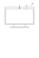
- FIG. 1 is a diagram showing an overview of a display device 100 according to an embodiment. Specifically, FIG. 1 is a front view of the display device 100 according to the embodiment, and shows components included in the display device 100 .
- the display device 100 is a so-called television having a display section 20 that displays still images or moving images.
- the display device 100 has a camera 10 for capturing an image above the display section 20 .
- the camera 10 captures an image in the direction in which a still image or moving image is displayed on the display unit 20 .
- the display device 100 analyzes an image captured by the camera 10 and determines whether or not a person (hereinafter collectively referred to as “user”) is shown in the image.
- the display device 100 analyzes the captured image and measures the distance between the user and the camera 10 (that is, the distance between the user and the display unit 20). Then, when the user and the display unit 20 are closer than a predetermined distance, the display device 100 issues a warning to avoid the proximity. As a result, the display device 100 prevents the user from approaching the display unit 20 , thereby preventing the user's visual acuity from deteriorating, colliding with the display device 100 , and overturning the display device 100 .
- the display device 100 displays an image on the display unit 20 that conveys that the user is leaving the display device 100, or emits a warning sound from a speaker (not shown in FIG. 1). Such processing will be described with reference to FIG. 2 and subsequent drawings.
- FIG. 2 is a diagram (1) for explaining display processing according to the embodiment.
- FIG. 2 shows a display device 100 installed in a living room and a user 50 who is a child watching video content displayed by the display device 100 .
- the user 50 is closer to the display device 100 than a preset distance.
- the display device 100 detects that the user 50 is viewing the display unit 20 and that the user 50 is closer to the display unit 20 than a predetermined distance based on the image recognition processing for the image captured by the camera 10. determined to be
- the display device 100 displays the first warning on the display unit 20 to the user 50 . Specifically, the display device 100 displays the warning frame 30 at the bottom of the display section 20 .
- the warning frame 30 has a warning text 32 (characters "Move away” in the example of FIG. 2) instructing the player to leave the screen, and a release button 34.
- a warning text 32 characters "Move away” in the example of FIG. 2
- a release button 34 At the stage of the first warning display shown in FIG. 2, only part of the warning frame 30 is displayed at the bottom of the display unit 20, and the actual warning frame 30 is shown by the dotted line in FIG. It has a wider viewing range.
- the user 50 or the parent's user viewing the display unit 20 together with the user 50 is prompted to move away from the display unit 20 by displaying the warning frame 30 on the display unit 20 being viewed.
- the warning frame 30 can be erased by pressing the cancel button 34 to temporarily cancel the warning processing. be able to.
- the display device 100 continues to measure the distance to the user 50 even after issuing the first warning that the warning frame 30 is displayed at the bottom of the display unit 20 . Then, if the user 50 is still within a predetermined distance from the display unit 20 after a predetermined time (for example, 3 seconds after the warning frame 30 is displayed) has elapsed, the display device 100 issues a second warning. emit.
- a predetermined time for example, 3 seconds after the warning frame 30 is displayed
- FIG. 3 is a diagram (2) for explaining display processing according to the embodiment.
- FIG. 3 shows user 50 continuing to be in close proximity to display device 100 .
- the display device 100 displays the entire warning frame 30 on the display unit 20 as a second warning.
- the display device 100 performs an animation display in which a part of the warning frame 30 is displayed slides upward, and transitions the screen so that the entire warning frame 30 is displayed on the display unit 20 .
- the warning frame 30 includes a warning text 32 and a cancel button 34, as well as a virtual image to prompt the user to leave the screen.
- a virtual image is a screen in which the user 50 is assumed to be the character 36 and the distance between the user 50 and the display unit 20 in the real space is virtually displayed on the screen.
- the virtual image includes an appropriate position display 38 and an arrow 40 prompting the direction of travel. These displays are automatically formed based on the information captured by camera 10 .
- the display device 100 performs processing such as gradually darkening the original image (image hidden behind the warning frame 30 ) that has been displayed on the display unit 20 . may As a result, the line of sight of the user 50 is attracted to the warning frame 30 instead of the standard image that has been displayed so far.
- the display device 100 may output a warning sound 42 such as "please move away from the TV".
- the character 36 on the screen is linked with the movement of the user 50 in the real space. That is, when the user 50 moves away from the display unit 20, the character 36 moves in the direction indicated by the arrow 40 with animation processing. Further, when the user 50 approaches the display unit 20 further, the character 36 moves in the direction opposite to the direction indicated by the arrow 40 with animation processing.
- the user 50 understands that the character 36 on the screen moves when he or she moves, and furthermore, by listening to the warning sound emitted from the display device 100, such as "Please go down to the circle on the screen and look", the user 50 can move to the appropriate position. Motivation to move to display 38 is provided. Accordingly, the display device 100 prevents the user 50 from approaching the display device 100 . In addition, the display device 100 emphasizes the appropriate position display 38 on the screen (blinking display, display brighter than other displays, etc.) to prompt the user 50 to move to the appropriate position display 38. may
- FIG. 4 is a diagram (3) for explaining display processing according to the embodiment.
- FIG. 4 shows an example in which the user 50 has moved out of the range of the predetermined distance at which the warning is issued.
- the display device 100 When the character 36 in the virtual image moves to the proper position display 38, the display device 100 performs effect processing such as lighting or blinking the proper position display 38, and then slides the warning frame 30 to the lower part of the display unit 20.
- the warning frame 30 is erased from the display section 20. Further, when the warning frame 30 is erased, the display device 100 restores the darkened image on the display unit 20 to the standard display.
- the user 50 can recognize that the screen display has returned to its original state according to his/her own behavior, and can change his/her behavior so as not to approach the display unit 20 thereafter. That is, according to the display processing according to the embodiment, it is possible to prevent the user 50 from approaching the display unit 20 and to encourage the user 50 not to approach the display unit 20 thereafter. can demonstrate.
- the display processing executed by the display device 100 has been described above. By the way, it is desirable that the user can arbitrarily determine how close the display device 100 is to issue a warning according to the size of the room in which the display device 100 is installed, the age of the user, and the like.
- the display device 100 executes measurement processing so that the user can arbitrarily set a predetermined distance for issuing a warning. This point will be described with reference to FIG. 5 and subsequent drawings.
- FIG. 5 is a diagram (1) for explaining the measurement process according to the embodiment.
- FIG. 5 shows a display device 100 and a user 60 who is an adult trying to set a predetermined distance for issuing a warning.
- the display device 100 When the display device 100 receives a request for setting a predetermined distance from the user 60, the display device 100 provides a setting screen as a user interface for setting. For example, as shown in FIG. 5, the display device 100 displays on the display unit 20 an instruction 62 including text prompting measurement, an imaging display 64 by the camera 10, and a measurement start button 68.
- FIG. 5 the display device 100 displays on the display unit 20 an instruction 62 including text prompting measurement, an imaging display 64 by the camera 10, and a measurement start button 68.
- the imaged display 64 is an image captured by the camera 10 of the user 60 trying to set the predetermined distance. That is, the imaged display 64 includes a person 66 corresponding to the imaged user 60 .
- the user 60 moves to a reference position where a warning is issued when the user 60 approaches the display device 100 any further, and presses the measurement start button 68 .
- the user 60 presses the measurement start button 68 after being in a position where the user views the display device 100 on a daily basis.
- the display device 100 displays a measurement availability determination 67 indicating whether the measurement process can be started.
- FIG. 6 is a diagram (2) for explaining the measurement process according to the embodiment.
- the display device 100 when the display device 100 finishes measuring the distance to the user 60, it displays on the display unit 20 an instruction 70 asking whether to set the measured distance as the predetermined distance.
- the display device 100 also displays the measurement result 72 of the distance to the person 66 on the imaging display 64 .
- a measurement result 72 is the result of measuring the distance from the display device 100 to the person 66 and is displayed near the person 66 .
- the user 60 presses the decision button 74 when setting the measurement result to the predetermined distance.
- the user 60 may request re-measurement in situations such as when the user 60 is not recognized, when an appropriate distance has not been measured, or when the user wants to set a longer or shorter distance. If the user 60 wants to set a distance slightly shorter or longer than the measured distance as the predetermined distance, the user 60 may set the predetermined distance by manually adjusting the measured distance.
- the display device 100 stores this setting information as a predetermined distance for issuing a warning.
- the display device 100 may store different settings of the predetermined distance for each user who sets the distance or for each room in which the setting is performed.
- measurement results and setting information may be uploaded to a cloud server via a network and imported into other devices.
- the display device 100 may import measurement results and setting information generated by other devices from the cloud server.
- the display device 100 displays an image on the display unit 20, and determines whether or not the user viewing the image and the display unit 20 are closer than a predetermined distance. judge.
- the display device 100 determines that the user and the display unit 20 are closer than the predetermined distance
- the display device 100 issues a first warning to the user, such as displaying a warning frame 30 on a part of the display unit 20. emitted.
- the display device 100 issues a second warning that displays the entire warning frame 30 .
- the display device 100 uses an image to recognize a user who is visually recognizing a video, and issues a warning to the recognized user. It is possible to reliably issue a warning to the user viewing the image without reacting to animals or the like.
- the display device 100 can prompt the user to return to the standard image by issuing a warning step by step so as to cover the display unit 20, thereby effectively discouraging the user from approaching the display device 100. can be suppressed.
- FIG. 7 is a diagram showing a configuration example of the display device 100 according to the embodiment.
- the display device 100 has a communication unit 110, a storage unit 120, a control unit 130, a detection unit 140, and an output unit 150.
- the display device 100 may have an input unit (for example, a touch display, operation buttons, etc.) that receives various operations from an administrator who manages the display device 100, the user 50, or the like.
- the communication unit 110 is implemented by, for example, a NIC (Network Interface Card), a network interface controller, or the like.
- the communication unit 110 is connected to the network N by wire or wirelessly, and transmits/receives information to/from an external device or the like via the network N.
- the network N is realized by a wireless communication standard or method such as Bluetooth (registered trademark), the Internet, Wi-Fi (registered trademark), UWB (Ultra Wide Band), LPWA (Low Power Wide Area), or the like.
- the detection unit 140 is a functional unit (sensor) for detecting various types of information.
- the detection unit 140 is, for example, an image sensor that records the imaged space as pixel information (still image or moving image).
- the camera 10 illustrated in FIG. 1 corresponds to an example of the detection unit 140 .
- the camera 10 is an image sensor that captures an image in a direction facing the display unit 20, and is arranged so as to be close to the display unit 20 as shown in FIG. embedded in the outer frame (bezel) of the display unit 20).
- the image sensor (camera 10) includes a pre-learned AI chip for image recognition of a human face and estimation of a user's skeleton based on image analysis. good too.
- the detection unit 140 may include a depth sensor (ToF sensor) that measures the distance to a user or object located in the space, a microphone that detects sounds in the space, and the like.
- ToF sensor depth sensor
- the detection unit 140 does not necessarily have to be provided inside the display device 100 .
- the detection unit 140 may be installed outside the display device 100 as long as it can transmit sensed information to the display device 100 using communication or the like.
- the output unit 150 is a functional unit that outputs video, audio, etc. to the outside.
- the output unit 150 includes a display 151 that displays video and a speaker 152 that outputs audio.
- the display unit 20 illustrated in FIG. 1 corresponds to an example of the output unit 150 .
- the storage unit 120 is implemented by, for example, a semiconductor memory device such as RAM (Random Access Memory) or flash memory, or a storage device such as a hard disk or optical disk.
- Storage unit 120 has setting storage unit 121 and warning information storage unit 122 .
- each storage unit will be described in order with reference to FIGS. 8 and 9.
- FIG. 1 A block diagram illustrating an exemplary computing environment in accordance with the present disclosure.
- FIG. 8 is a diagram showing an example of the setting storage unit 121 according to the embodiment.
- the setting storage unit 121 has items such as "setting ID” and "setting distance". 8 and 9, the information stored in the storage unit 120 may be conceptually indicated as “A01”, but in reality, each piece of information described later is stored in the storage unit 120.
- FIG. 8 is a diagram showing an example of the setting storage unit 121 according to the embodiment.
- the setting storage unit 121 has items such as "setting ID” and "setting distance”.
- the information stored in the storage unit 120 may be conceptually indicated as “A01”, but in reality, each piece of information described later is stored in the storage unit 120.
- “Setting ID” is identification information for identifying the setting of the distance (predetermined distance) that serves as a reference for determining that the display unit 20 is in proximity. “Set distance” is information about a predetermined distance set for determining that a person has approached the display unit 20 . For example, the set distance may be set for each user, or may be used for each space such as a room in which the display device 100 is installed.
- FIG. 9 is a diagram showing an example of the warning information storage unit 122 according to the embodiment. As shown in FIG. 9, the warning information storage unit 122 has items such as "warning information ID" and "warning information”.
- Warning information ID is identification information that identifies warning information used for display processing.
- the "warning information” includes image data of a warning screen used for warning, warning audio data, data describing operation processing such as how the image changes, and the like.
- the control unit 130 for example, by CPU (Central Processing Unit), MPU (Micro Processing Unit), GPU (Graphics Processing Unit), etc., the program stored inside the display device 100 (for example, the display program according to the present disclosure) It is realized by executing RAM (Random Access Memory) etc. as a work area. Also, the control unit 130 is a controller, and may be realized by an integrated circuit such as an ASIC (Application Specific Integrated Circuit) or an FPGA (Field Programmable Gate Array).
- ASIC Application Specific Integrated Circuit
- FPGA Field Programmable Gate Array
- control unit 130 has a display control unit 131, a measurement unit 132, a determination unit 133, and an output control unit 134.
- the display control unit 131 controls to display the image on the display unit 20 (display 151) by outputting the image to the output unit 150.
- the measurement unit 132 Upon receiving a distance measurement request from the user, the measurement unit 132 measures the distance from the user located within the detection range of the sensor to the display unit 20 based on the information acquired by the sensor. Further, when receiving a request for setting the predetermined distance after the measurement, the measuring unit 132 sets the measured distance as the predetermined distance. After setting the predetermined distance, the measurement unit 132 stores this information in the setting storage unit 121 .
- the measurement unit 132 measures the distance from the user located within the detection range (field angle range) of the camera 10 to the display unit 20 based on the analysis of the image captured by the camera 10 .
- Distance measurement is performed based on existing image analysis processing (processing performed by an AI chip or the like incorporated in the camera 10).
- the measurement unit 132 provides a user interface displayed on the display unit 20 as shown in FIGS. 4 and 5 when measuring the distance.
- the user interface includes an image captured by camera 10 (that is, an image showing a situation where display device 100 is capturing an image of the user).
- the user interface displays the measurement result of the distance from the user located in the detection range of the camera 10 to the display unit 20 superimposed on the image captured by the camera 10. .
- the measurement unit 132 receives, via the user interface, whether or not to set the measurement result as the predetermined distance.
- a user can easily and appropriately set a predetermined distance by setting while looking at a user interface that allows him/herself to be photographed and the measured distance to be confirmed at a glance.
- the camera 10 includes an AI chip having a pre-learned model that has learned a specific object, such as human face recognition, so that it can recognize whether the object being imaged is a person or not. can be done.
- the measurement unit 132 acquires a flag indicating whether or not a person is present within the angle of view from the camera 10, and measures the distance to the person when the person is present within the angle of view. Note that when the angle of view includes a plurality of people, the measurement unit 132 may measure the distance to the person closest to the display unit 20, or may return an error.
- the determination unit 133 determines whether the user viewing the display unit 20 and the display unit 20 are closer than a predetermined distance based on information acquired by the sensor (detection unit 140).
- the determination unit 133 determines whether the user and the display unit 20 are closer than a predetermined distance.
- the determination unit 133 may determine whether or not the user is viewing the display unit 20 based on the user's skeleton estimation (bone estimation) recognized in the image. This is because there is no need to issue a warning if the user is not gazing at the display unit 20 . Specifically, when the determination unit 133 determines that the user's face captured by the camera 10 is sideways or backward based on the skeleton estimation, the determination unit 133 determines that the display unit 20 is not viewed. Thereby, the determination unit 133 can exclude a user who simply crosses in front of the display device 100 or a user who is not gazing at the display unit 20 from the target of the warning.
- the determination unit 133 can exclude a user who simply crosses in front of the display device 100 or a user who is not gazing at the display unit 20 from the target of the warning.
- the determination unit 133 may determine whether the user viewing the display unit 20 satisfies a predetermined criterion based on the estimation of the user's skeleton (bone estimation) recognized in the image. This is because the user who visually recognizes the display unit 20 may be a user who does not need to be warned. Specifically, when the determination unit 133 determines that the user captured by the camera 10 is under a predetermined age or is a preset user based on the skeleton estimation, the determination unit 133 determines that the user is subject to warning. . Accordingly, the determination unit 133 can display a warning only for users who need to be warned.
- the determining unit 133 determines that the user viewing the display unit 20 and the display unit 20 are closer than the predetermined distance, a part of the warning frame 30 is displayed on the display unit 20 as shown in FIG. A first warning is given that Further, the determination unit 133 determines whether or not the user and the display unit 20 continue to be closer than a predetermined distance for a predetermined time (for example, 3 seconds) after the first warning is output. judge. If the determination unit 133 determines that the user and the display unit 20 have continued to be closer than the predetermined distance for a predetermined time after the first warning was output, a second warning is issued. be. Further, when the determination unit 133 determines that the distance between the user and the display unit 20 is further reduced after the output of the first warning, the second warning is issued without waiting for the elapse of the predetermined time. may
- the output control unit 134 When the determination unit 133 determines that the user and the display unit 20 are closer than the predetermined distance, the output control unit 134 outputs a first warning to the user. Note that when the determination unit 133 determines that the user and the display unit 20 are closer than a predetermined distance and determines that the user is visually recognizing the display unit 20, the output control unit 134 A first warning may be output to the user.
- the output control unit 134 has a larger display area than the first warning screen (corresponding to the entire warning screen; for example, the warning frame 30 whose entirety is displayed as shown in FIG. 3 corresponds).
- a small second warning screen (corresponding to part of the warning screen, for example, corresponding to the warning frame 30 shown in FIG. 2) is output so as to be superimposed on at least part of the image displayed on the display unit 20 .
- the output control unit 134 Output a second warning to the user.
- the output control unit 134 displays the first warning screen on which an instruction to move away from the display unit is displayed based on the information acquired by the sensor as the second warning.
- the output control unit 134 outputs an entire warning screen displaying an instruction to move away from the display unit 20 so as to be superimposed on the image displayed on the display unit 20. . That is, the output control unit 134 first displays the second warning screen corresponding to part of the first warning screen as the first warning, and then displays the first warning screen, which is the entire warning screen, as the second warning. display.
- the output control unit 134 may output the entire warning screen and output a voice instruction (warning voice) to move away from the display unit 20 .
- the output control unit 134 when displaying the entire warning screen, the output control unit 134 outputs the entire warning screen to the display unit 20, accompanied by animation display of moving the warning screen, which was only partially displayed on the display unit 20. good too. For example, as shown in FIGS. 2 and 3 , the output control unit 134 slides the warning frame 30 displayed at the bottom of the display unit 20 to the middle of the display unit 20 as time elapses. Output processing may be performed so that the entire warning frame 30 is displayed in the vicinity.
- the output control unit 134 may perform filter processing in conjunction with the passage of time on the image on which the warning screen is superimposed. Specifically, the output control unit 134 may perform filter processing such that the original image on which the warning screen is superimposed is gradually reduced in luminance to become darker. As a result, the user is motivated to return to the original image as soon as possible, and is encouraged to move away from the display device 100 .
- the filtering process is not limited to brightness adjustment, and may be any process that changes the original image, such as changing the resolution or performing mosaic processing.
- the output control unit 134 displays a warning screen in which the character corresponding to the user and the first object corresponding to the display unit 20 are separated from the display unit 20 by a predetermined distance.
- a virtual image including a second object indicating the position of the object may be displayed.
- the output control unit 134 may animate the character in conjunction with the actual distance between the user and the display unit 20 .
- the output control unit 134 moves the character to the second object in the virtual image in conjunction with the movement.
- the second object may be subjected to predetermined effect processing.
- the output control unit 134 performs effect processing such as blinking the second object (the mark indicating the predetermined distance).
- effect processing such as blinking the second object (the mark indicating the predetermined distance).
- the output control unit 134 displays an animation that moves the warning screen out of the display unit 20, and displays the warning screen. is erased from the display unit 20.
- the output control unit 134 may erase the warning screen from the display unit 20 when receiving a request from the user to stop outputting the warning via the warning screen after displaying the warning screen. For example, when the user presses the cancel button 34 shown in FIG. 2 on the screen, the output control unit 134 cancels subsequent display processing and clears the warning screen.
- FIG. 10 is a flowchart showing the flow of measurement processing according to the embodiment.
- the display device 100 determines whether or not a measurement request has been received from the user (step S101). For example, the display device 100 provides an initial setting screen or the like for a predetermined distance determined to be close to the display device 100, and receives a measurement request from the user. If the measurement request is not accepted (step S101; No), the display device 100 waits until the request is accepted.
- step S101 if a measurement request has been received (step S101; Yes), the display device 100 checks whether the camera 10 provided in the display device 100 is covered with a cover or the like (step S102). If the camera 10 is blocked (step S102; No), the display device 100 warns the user to remove the cover of the camera 10 (step S103).
- step S102 the display device 100 captures an image of the front of the display unit 20 with the camera 10, and recognizes a person from the obtained image (step S104).
- the display device 100 measures the distance to the person closest to the display unit 20 (step S105).
- the display device 100 displays the measured distance near the person in the image of the camera 10 reflected on the setting screen (user interface) (step S106).
- the “person” in this case may be the same as the user who made the measurement request, or may be a different person.
- the display device 100 determines whether or not it has received from the user that the measured distance is to be set as the predetermined distance (step S107). If the setting is not accepted from the user (step S107; No), the display device 100 accepts another measurement request. On the other hand, when receiving the setting from the user (step S107; Yes), the display device 100 sets the measured distance as the predetermined distance (step S108).
- FIG. 11 is a flowchart showing the flow of display processing according to the embodiment.
- the display device 100 controls the display unit 20 to display a standard image before performing display processing (step S201). Then, the display device 100 always captures an image with the camera 10 arranged near the display unit 20, and determines whether or not a person is recognized based on the captured image (step S202). If the person is not recognized (step S202; No), the display device 100 continues displaying the standard screen.
- step S202 determines whether the person is closer to the display unit 20 than the predetermined distance. If the distance is not closer than the predetermined distance (step S203; No), the display device 100 continues displaying the standard screen.
- the display device 100 issues a first stage warning (step S204). For example, the display device 100 displays only part of the warning screen on the lower part of the display unit 20 and prompts the person to move away from the display unit 20 .
- the display device 100 determines whether or not the approach to the display unit 20 continues for a predetermined time (step S205).
- a predetermined time for example, 3 seconds
- the display device 100 erases the warning screen and returns to displaying the standard screen. do.
- step S206 the display device 100 slides a part of the warning screen displayed at the bottom of the display unit 20 and displays the entire warning screen on the display unit 20 by superimposing it on the original image.
- the display device 100 determines whether or not the approach to the display unit 20 continues for a predetermined time (step S207).
- the predetermined time in this case may be set to a time different from that in step S205 (for example, 1 second).
- the display device 100 erases the warning screen and returns to displaying the standard screen.
- step S207 the display device 100 further executes step-by-step screen display etc. for the second stage warning (step S206).
- the display device 100 performs display processing such as gradually darkening the original image on which the warning screen is superimposed, and transitions to a state in which it is difficult for a person to visually recognize the image. Thereby, the display device 100 prompts the person to leave the display unit 20 .
- the display device 100 receives from the user an instruction to end the display of the video (when the power of the display device 100 as a television is turned off, etc.) or when the cancel button 34 is pressed, the display process exit.
- the display device 100 may measure the distance using a depth sensor (ToF sensor), an infrared sensor, or the like instead of measuring the distance to the person based on image analysis captured by the camera 10 .
- the display device 100 acquires map information of the space where the user is located using techniques such as SLAM (Simultaneous Localization and Mapping) using depth sensors and image sensors, and measures the distance to the user from this information.
- SLAM Simultaneous Localization and Mapping
- the display device 100 may have a plurality of cameras instead of having one camera 10 near the display unit 20 .
- a plurality of cameras are connected to the display device 100, there is a possibility that misrecognition may occur.
- a flexible configuration may be adopted, such as enabling the camera and using the image obtained from the camera for processing.
- the display unit 20 is exemplified as an object to prevent the user from approaching.
- the processing according to the embodiment may be applied not only to prevent the user from approaching the display unit 20 but also to prevent the user from approaching a predetermined target near the camera 10 .
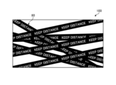
- FIG. 12 is a diagram (1) for explaining display processing according to the modification.
- the display device 100 displays a superimposed display 80 so as to cover the original video as a second warning, for example.
- the superimposed display 80 is in the form of a tape on which characters are written to warn the user to stay away from the display unit 20, and is drawn by animation processing so as to cover a wide range of images as time elapses.
- the display device 100 determines whether or not the user and the display unit 20 continue to be closer than a predetermined distance for a predetermined time after the first warning is output. Then, when the display device 100 determines that the user and the display unit 20 have continued to be closer than the predetermined distance for a predetermined time, the display device 100 issues an object superimposed on the image as a second warning to the user. An object is displayed in animation, the range of which is superimposed on the image increases in conjunction with the elapsed time. As a result, the display device 100 can prevent the user from continuing to view the video and strongly prompt the user to move away from the display unit 20 beyond the predetermined distance. Note that the display device 100 may output the superimposed display 80 as the first warning instead of the second warning.
- the display device 100 may perform different screen display processing besides the example shown in FIG. An example of such modification will be described with reference to FIG.
- FIG. 13 is a diagram (2) for explaining display processing according to the modification.
- the display device 100 superimposes a shadow 82 corresponding to the user on the image as a second warning, for example.
- the shadow 82 is an object corresponding to the user captured by the camera 10 , and is, for example, a silhouette that moves in conjunction with the movement of the user captured by the camera 10 .
- the user is motivated to move away from the display unit 20 because the user feels that the image is hidden due to his or her own actions.
- the display device 100 determines that the user and the display unit 20 continue to be closer than the predetermined distance for a predetermined time, a second warning to the user is superimposed on the video.
- a shadow 82 that is an object linked to the user's motion information acquired by the camera 10 is displayed.
- the display device 100 can prompt the user to remove the shadow 82 that disturbs viewing of the video, that is, prompt the user to move away from the display unit 20 beyond the predetermined distance.
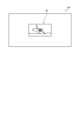
- FIG. 14 is a diagram (3) for explaining display processing according to the modification.
- the display device 100 performs a process of reducing the original video over time as the second warning, for example.
- An image 84 shown in FIG. 14 shows the original image that has been reduced over time.
- the display device 100 may perform animation processing such that the image gradually moves away from the screen.
- the display device 100 determines that the user and the display unit 20 are closer than the predetermined distance for a predetermined time, the display device 100 adjusts the range in which the image is displayed in conjunction with the elapsed time. You may control to narrow. Accordingly, the display device 100 can prompt the user to move away from the display unit 20 beyond the predetermined distance in order to continue viewing the video.
- FIG. 15 is a diagram (1) for explaining the measurement process according to the modification.
- the display device 100 measures the distance to the person displayed in the captured image 86. Then, the display device 100 performs the process of measuring the distance to the user while displaying the image 86 on the display unit 20 so that the user can visually recognize it (step S301).
- the display device 100 may display an image 88 in which the grid display is superimposed on the original image by animation processing during measurement.
- the user can watch the display transition from image 86 to image 88 on the user interface.
- the display device 100 can entertain the user during measurement and motivate the user to actively perform the measurement.
- FIG. 16 is a diagram (2) for explaining the measurement processing according to the modification.
- the display device 100 measures the distance to the person displayed in the captured image 86, as in the example of FIG. Then, the display device 100 performs the process of measuring the distance to the user while displaying the image 86 on the display unit 20 so that the user can visually recognize it (step S302).
- the display device 100 may display an image 90 in which scanning lines that scan the image 86 from above are superimposed on the original image by animation processing during measurement.
- the user can view the transition from image 86 to image 90 on the user interface that displays the image of the user being captured.
- the display device 100 when displaying the measurement result of the distance from the user located in the detection range of the camera 10 to the display unit 20 on the user interface, recognizes the distance in the image. Effect processing is performed to indicate the progress of the measurement for the user who performed the measurement. By applying such a visual effect, the display device 100 can provide interest to the user during measurement and accurately inform the user which person in the image has been recognized by the display device 100. Therefore, the display device 100 can avoid problems such as erroneous measurement or setting of an unnatural distance as the predetermined distance.
- each component of each device illustrated is functionally conceptual and does not necessarily need to be physically configured as illustrated.
- the specific form of distribution and integration of each device is not limited to the one shown in the figure, and all or part of them can be functionally or physically distributed and integrated in arbitrary units according to various loads and usage conditions. Can be integrated and configured.
- the display device according to the present disclosure includes a display control unit (display control unit 131 in the embodiment), a determination unit (determination unit 133 in the embodiment), and an output control unit (output control unit 134 in the embodiment).
- the display control unit displays an image on the display unit (display unit 20 in the embodiment).
- the determination unit determines whether or not a person viewing the display unit and the display unit are closer than a predetermined distance based on information acquired by the sensor.
- the output control unit outputs a first warning to the person when the determination unit determines that the person and the display unit are closer than a predetermined distance.
- the display device determines the proximity of the person viewing the image to the display unit and issues a warning to the person, thereby making the person's approach to the display unit more effective. can be effectively suppressed.
- the determination unit determines whether or not the person and the display unit are closer than a predetermined distance based on the analysis of the image captured by the image sensor (camera 10 in the embodiment).
- the display device recognizes a person based on image analysis and determines the distance between the recognized person and the display unit, thereby excluding the approach of non-humans such as animals and accurately determining the approach of the person. can do.
- the determination unit determines whether or not the person is visually recognizing the display unit based on the skeleton estimation of the person recognized in the image.
- the output control unit outputs the first output to the person. output a warning of
- the display device can exclude a person or the like who simply crosses the front of the display unit from the determination target, so that a warning can be reliably issued only to the person viewing the image. can be done.
- the output control unit displays a first warning screen (meaning the entire warning screen In the embodiment, the warning frame 30 displayed in its entirety as shown in Fig. 3 corresponds) is output as the second warning. Further, after the first warning is output, the output control unit outputs a first warning screen having a smaller display area than the first warning screen on which an instruction to move away from the display unit is displayed based on information acquired by the sensor. 2 A warning screen (meaning a part of the warning screen; in the embodiment, the warning frame 30 shown in FIG. 2 corresponds) is output so as to be superimposed on at least part of the image displayed on the display unit 20 . Also, the second warning screen corresponds to part of the first warning screen.
- the display device displays only a part of the warning screen as the first warning, so that viewing of the video is not hindered and the user can be encouraged to leave the display unit.
- the display device can effectively suppress approaching by giving a stepwise warning as compared with a case where a simple warning is issued.
- the determination unit determines whether or not the person and the display unit continue to be closer than a predetermined distance for a predetermined time after the first warning is output.
- the output control unit outputs a second warning to the person when it is determined by the determination unit that the person and the display unit continue to be closer than the predetermined distance for a predetermined time.
- the display device can effectively suppress approach by issuing a step-by-step warning compared to simply issuing a warning.
- the output control unit superimposes, as a second warning, the first warning screen, which is the entire warning screen on which an instruction to leave the display unit is displayed, on at least a part of the image displayed on the display unit. output to let
- the display device can more strongly urge the person to move away from the display unit, compared to a state in which a part of the warning screen is displayed.
- the output control unit outputs a voice instruction (audio 42 in the embodiment) to move away from the display unit along with the first warning screen.
- the display device can strongly urge the person to move away from the display unit by emitting a sound along with the warning screen.
- the output control unit displays the first warning, which is the entire warning screen on which an instruction to move away from the display unit is displayed, accompanied by an animation display that moves the second warning screen, which was only partially displayed on the display unit. Outputs the screen to the display unit.
- the display device outputs the entire warning screen to the display unit with screen effects such as animation display, thereby making the person strongly aware of moving away from the display unit.
- the determination unit determines whether or not the person has moved to a position away from the display unit by more than a predetermined distance after the second warning is output.
- the output control unit controls the image on which the first warning screen is superimposed in conjunction with the passage of time. Apply filtering.
- the display device reduces the visibility of the image by performing filter processing such as reducing the brightness of the image. Thereby, the display device can strongly urge the person to move away from the display unit.
- the output control unit displays a warning screen as a character (character 36 in the embodiment) corresponding to a person, a first object corresponding to the display unit, and a second object indicating a position away from the display unit by a predetermined distance.
- a virtual image including an object is displayed, and the character is animated in conjunction with the actual distance between the person and the display unit.
- the display device displays an animation linked to the person and prompts the user to move along the display, thereby effectively prompting the user to leave the vicinity of the display unit.
- the determination unit determines whether or not the person has moved to a position away from the display unit by more than a predetermined distance after the second warning is output.
- the output control unit moves the character to the second object in the virtual image in conjunction with the movement. Predetermined effect processing is applied to the object.
- the display device performs processing such as blinking the second object when the person moves, so that the child or the like who is amused by the processing can effectively move away from the vicinity of the display unit. can encourage
- the determination unit determines whether or not the person has moved to a position away from the display unit by more than a predetermined distance after the second warning is output.
- the output control unit displays the warning screen from the display unit with an animation display that moves the warning screen out of the display unit. to erase.
- the display device can effectively encourage the person to leave the vicinity of the display unit by erasing the warning screen and restoring the original image when the person leaves the display unit.
- the output control unit receives a request to stop the output of the warning via the warning screen after displaying the warning screen, the output control unit erases the warning screen from the display unit.
- the display device can eliminate the annoyance of outputting a warning screen in an unnecessary situation by erasing the warning screen in response to a request.
- the display device when the display device receives the measurement request, the display device measures the distance from the person located in the detection range of the sensor to the display unit based on the information acquired by the sensor, and sets the measured distance as the predetermined distance. It further includes a measurement unit (measurement unit 132 in the embodiment). The determination unit determines whether or not a person viewing the display unit and the display unit are closer than a predetermined distance, using the distance set by the measurement unit as a predetermined distance. Further, when receiving a request for setting the predetermined distance after the measurement, the measuring unit sets the measured distance as the predetermined distance.
- the display device can arbitrarily set a predetermined distance that serves as a reference for proximity according to a person's request. As a result, the display device can issue a warning that matches the daily lifestyle of each person.
- the measurement unit measures the distance from the person located in the detection range of the image sensor to the display unit based on the analysis of the image captured by the image sensor.
- the display device can quickly and accurately measure the distance to the person by measuring the distance based on image analysis.
- the measurement unit is a user interface displayed on the display unit, and includes an image captured by the image sensor and the measurement result of the distance from the person located in the detection range of the sensor to the display unit superimposed on the image.
- a request for setting a predetermined distance is received via a user interface including
- the display device enables the person to visually understand the setting procedure by making the captured image visible to the person.
- the measurement unit when displaying the measurement result of the distance from the person located in the detection range of the sensor to the display unit on the user interface, the measurement unit performs effect processing that indicates the progress of the measurement for the person recognized in the image. .
- the display device can provide the person with a setting procedure accompanied by a visual effect by performing effect processing such as scanning the person.
- the display device further includes, as a sensor, an image sensor (camera 10 in the embodiment), which is an image sensor that captures an image in a direction facing the display section and is arranged so as to be close to the display section.
- the determination unit determines whether or not the person and the display unit are closer than a predetermined distance based on analysis of an image captured by the provided image sensor.
- the display device may have a configuration in which it is equipped with an image sensor. Thereby, the display device can accurately recognize a person who is close to the display device.
- FIG. 17 is a hardware configuration diagram showing an example of a computer 1000 that implements the functions of the display device 100.
- the computer 1000 has a CPU 1100 , a RAM 1200 , a ROM (Read Only Memory) 1300 , a HDD (Hard Disk Drive) 1400 , a communication interface 1500 and an input/output interface 1600 .
- Each part of computer 1000 is connected by bus 1050 .
- the CPU 1100 operates based on programs stored in the ROM 1300 or HDD 1400 and controls each section. For example, the CPU 1100 loads programs stored in the ROM 1300 or HDD 1400 into the RAM 1200 and executes processes corresponding to various programs.
- the ROM 1300 stores a boot program such as BIOS (Basic Input Output System) executed by the CPU 1100 when the computer 1000 is started, and programs dependent on the hardware of the computer 1000.
- BIOS Basic Input Output System
- the HDD 1400 is a computer-readable recording medium that non-temporarily records programs executed by the CPU 1100 and data used by such programs.
- HDD 1400 is a recording medium that records a display program according to the present disclosure, which is an example of program data 1450 .
- a communication interface 1500 is an interface for connecting the computer 1000 to an external network 1550 (for example, the Internet).
- CPU 1100 receives data from another device via communication interface 1500, and transmits data generated by CPU 1100 to another device.
- the input/output interface 1600 is an interface for connecting the input/output device 1650 and the computer 1000 .
- the CPU 1100 receives data from input devices such as a keyboard and mouse via the input/output interface 1600 .
- the CPU 1100 transmits data to an output device such as a display, a speaker, or a printer via the input/output interface 1600 .
- the input/output interface 1600 may function as a media interface for reading a program or the like recorded on a predetermined recording medium.
- Media include, for example, optical recording media such as DVD (Digital Versatile Disc) and PD (Phase change rewritable disk), magneto-optical recording media such as MO (Magneto-Optical disk), tape media, magnetic recording media, semiconductor memories, etc. is.
- optical recording media such as DVD (Digital Versatile Disc) and PD (Phase change rewritable disk)
- magneto-optical recording media such as MO (Magneto-Optical disk)
- tape media magnetic recording media
- magnetic recording media semiconductor memories, etc. is.
- the CPU 1100 of the computer 1000 implements the functions of the control unit 130 and the like by executing the display program loaded on the RAM 1200.
- the HDD 1400 also stores the display program according to the present disclosure and the data in the storage unit 120 .
- CPU 1100 reads and executes program data 1450 from HDD 1400 , as another example, these programs may be obtained from another device via external network 1550 .
- the present technology can also take the following configuration.
- a display control unit that displays an image on a display unit; a determination unit that determines whether or not a person viewing the display unit and the display unit are closer than a predetermined distance based on information acquired by a sensor; an output control unit that outputs a first warning to the person when the determination unit determines that the person and the display unit are closer than a predetermined distance; A display device.
- the output control unit is After the first warning is output, based on the information acquired by the sensor, a first warning screen displaying an instruction to leave the display unit is output as a second warning.
- the output control unit is As the first warning, a second warning screen having a smaller display area than the first warning screen is output so as to be superimposed on at least a part of the image displayed on the display unit.
- the second warning screen corresponds to part of the first warning screen, The display device according to (3) above.
- the determination unit is After the first warning is output, determining whether or not a state in which the person and the display unit are closer than a predetermined distance continues for a predetermined time, The output control unit is outputting a second warning to the person when it is determined by the determination unit that the person and the display unit continue to be closer than a predetermined distance for a predetermined time; The display device according to any one of (2) to (4) above.
- the output control unit is As the second warning, a first warning screen, which is the entire warning screen displaying an instruction to leave the display unit, is output so as to be superimposed on at least a part of the image displayed on the display unit. do, The display device according to (4) above. (7) The output control unit is Along with the first warning screen, outputting a voice instruction to leave the display unit; The display device according to any one of (2) to (6). (8) The output control unit is Displaying the first warning screen, which is the entirety of the warning screen on which an instruction to leave the display is displayed, accompanied by an animation display of moving the second warning screen, only a part of which was displayed on the display. output to the The display device according to (6) above.
- the determination unit is After the second warning is output, determining whether the person has moved to a position more than a predetermined distance from the display unit,
- the output control unit is When the determination unit determines that the person has not moved to a position more than a predetermined distance from the display unit, a filter linked to the passage of time is applied to the image on which the first warning screen is superimposed. to process, The display device according to (5) above.
- the output control unit is A virtual image including a character corresponding to the person, a first object corresponding to the display unit, and a second object indicating a position away from the display unit by a predetermined distance or more is displayed as the first warning screen.
- the determination unit is After the second warning is output, determining whether the person has moved to a position more than a predetermined distance from the display unit,
- the output control unit is When the determination unit determines that the person has moved to a position away from the display unit by more than a predetermined distance, the character is moved to the second object in the virtual image in conjunction with the movement, and subjecting the second object to predetermined effect processing;
- the display device according to (10) above.
- (12) When a measurement request is received, the distance from a person located in the detection range of the sensor to the display unit is measured based on the information acquired by the sensor, and the measured distance is set as the predetermined distance.
- the determination unit is Determining whether the distance set by the measurement unit is the predetermined distance, and the person viewing the display unit and the display unit are closer than the predetermined distance; The display device according to any one of (1) to (11).
- the measuring unit Upon receiving the measurement request, measuring the distance from the person located in the detection range of the image sensor to the display unit based on the analysis of the image captured by the image sensor; The display device according to (12) above.
- the measuring unit The display device according to (13), wherein when a request for setting a predetermined distance is received after measurement, the measured distance is set as the predetermined distance.
- the measuring unit A user interface displayed on the display unit, wherein an image captured by the image sensor and a measurement result of the distance from the person located in the detection range of the sensor to the display unit are superimposed on the image. receiving a request to set the predetermined distance via a user interface including The display device according to (14) above.
- the determination unit is Determining whether the person and the display unit are closer than a predetermined distance based on analysis of the image captured by the image sensor; The display device according to any one of (1) to (15) above.
- the determination unit is determining whether the person is visually recognizing the display unit based on the estimated skeleton of the person recognized in the image;
- the output control unit is When the determination unit determines that the person and the display unit are closer than a predetermined distance and determines that the person is visually recognizing the display unit, outputs 1 warning,
- the display device according to (16) above.
- the display device according to any one of (16) and (17) above.
- the computer Display the image on the display, determining whether or not a person viewing the display unit and the display unit are closer than a predetermined distance based on information acquired by a sensor; When the determination determines that the person and the display unit are closer than a predetermined distance, outputting a first warning to the person.
- display method including (20) the computer, a display control unit that displays an image on a display unit; a determination unit that determines whether or not a person viewing the display unit and the display unit are closer than a predetermined distance based on information acquired by a sensor; an output control unit that outputs a first warning to the person when the determination unit determines that the person and the display unit are closer than a predetermined distance; display program to function as
Landscapes
- Engineering & Computer Science (AREA)
- Theoretical Computer Science (AREA)
- General Physics & Mathematics (AREA)
- Multimedia (AREA)
- Signal Processing (AREA)
- General Engineering & Computer Science (AREA)
- Physics & Mathematics (AREA)
- Human Computer Interaction (AREA)
- Databases & Information Systems (AREA)
- Computer Networks & Wireless Communication (AREA)
- Business, Economics & Management (AREA)
- Emergency Management (AREA)
- User Interface Of Digital Computer (AREA)
- Controls And Circuits For Display Device (AREA)
- Control Of Indicators Other Than Cathode Ray Tubes (AREA)
Abstract
表示装置(100)は、映像を表示部(20)に表示する表示制御部(131)と、センサにより取得される情報に基づいて、前記表示部を視認する人物と前記表示部とが所定距離よりも近接しているか否かを判定する判定部(133)と、前記判定部によって前記人物と前記表示部とが所定距離よりも近接していると判定されると、当該人物に対して第1の警告を出力する出力制御部(134)と、を備える。
Description
本開示は、対象への接近を検知するとともに接近に関する警告を発する表示装置、表示方法および表示プログラムに関する。
近年、大型テレビの市場拡大に伴い、各家庭のリビングルーム等に大型テレビが設置される機会が増大している。子どもは特に映像にのめり込む傾向にあるため、大型テレビに接近して視聴する傾向がある。このため、子供の視力の低下のおそれや、装置への衝突や転倒させる危険も生じる。
この点に関して、テレビ近傍に子どもが所在することを検知し、検知が所定回数を超えると警告を発することで、装置に子どもが接近することを防止する技術が提案されている(例えば、特許文献1)。
今後も家庭に導入されるテレビの大型化は進むとみられ、テレビへの近接を防止するためには引き続き対策を講じる必要がある。
そこで、本開示では、所定の対象への人物の接近をより効果的に抑制することができる表示装置、表示方法および表示プログラムを提案する。
上記の課題を解決するために、本開示に係る一形態の表示装置は、映像を表示部に表示する表示制御部と、センサにより取得される情報に基づいて、前記表示部を視認する人物と前記表示部とが所定距離よりも近接しているか否かを判定する判定部と、前記判定部によって前記人物と前記表示部とが所定距離よりも近接していると判定されると、当該人物に対して第1の警告を出力する出力制御部と、を備える。
以下に、実施形態について図面に基づいて詳細に説明する。なお、以下の各実施形態において、同一の部位には同一の符号を付することにより重複する説明を省略する。
以下に示す項目順序に従って本開示を説明する。
1.実施形態
1-1.実施形態に係る表示処理の概要
1-2.実施形態に係る表示装置の構成
1-3.実施形態に係る表示処理の手順
1-4.実施形態に係る変形例
2.その他の実施形態
3.本開示に係る表示装置の効果
4.ハードウェア構成
1.実施形態
1-1.実施形態に係る表示処理の概要
1-2.実施形態に係る表示装置の構成
1-3.実施形態に係る表示処理の手順
1-4.実施形態に係る変形例
2.その他の実施形態
3.本開示に係る表示装置の効果
4.ハードウェア構成
(1.実施形態)
(1-1.実施形態に係る表示処理の概要)
図1を用いて、本開示に係る表示処理を実行する表示装置100について説明する。図1は、実施形態に係る表示装置100の概要を示す図である。具体的には、図1は、実施形態に係る表示装置100の正面図であり、表示装置100が含む構成要素を示す。
(1-1.実施形態に係る表示処理の概要)
図1を用いて、本開示に係る表示処理を実行する表示装置100について説明する。図1は、実施形態に係る表示装置100の概要を示す図である。具体的には、図1は、実施形態に係る表示装置100の正面図であり、表示装置100が含む構成要素を示す。
図1に示したように、表示装置100は、静止画像または動画像を表示する表示部20を有する、いわゆるテレビである。表示装置100は、表示部20の上部に画像を撮像するカメラ10を有する。カメラ10は、表示部20で静止画像または動画像を表示する方向に対して、画像の撮像を行う。表示装置100は、カメラ10で撮像した画像を解析し、画像に人物(以下、「ユーザ」と総称する)が映っているか否かを判定する。
また、表示装置100は、撮像した画像を解析し、ユーザとカメラ10までの距離(すなわちユーザと表示部20までの距離)を計測する。そして、表示装置100は、ユーザと表示部20とが所定距離よりも近接した場合に、近接を回避するよう警告を発する。これにより、表示装置100は、ユーザが表示部20に近づくことを抑制し、ユーザの視力の低下や、表示装置100への衝突や、表示装置100を転倒させることを防止する。
具体的には、表示装置100は、表示部20に表示装置100から離れる旨を伝達するような画像を表示したり、スピーカ(図1への図示は省略する)から警告音声を発する。かかる処理について、図2以下を用いて説明する。
図2は、実施形態に係る表示処理を説明するための図(1)である。図2には、リビングルームに設置された表示装置100と、表示装置100が表示した映像コンテンツを視聴している子どもであるユーザ50とを示す。
図2の例において、ユーザ50は、予め設定された所定距離を超えて表示装置100に近接している。このとき、表示装置100は、カメラ10が撮像した画像に対する画像認識処理に基づいて、ユーザ50が表示部20を視聴していること、および、ユーザ50が所定距離よりも表示部20に近接していると判定する。
この場合、表示装置100は、ユーザ50に対して、表示部20に第1の警告を表示する。具体的には、表示装置100は、表示部20の下部に警告枠30を表示する。
警告枠30は、画面から離れるよう指示する旨の警告文32(図2の例では「Move away」の文字)と、解除ボタン34とを有する。なお、図2に示す第1の警告表示の段階では、警告枠30の一部のみが表示部20の下部に表示されており、実際の警告枠30は、図2の点線で示すように、より広い表示範囲を有する。
ユーザ50、もしくは、ユーザ50と一緒に表示部20を視聴している保護者のユーザは、視聴中の表示部20に警告枠30が表示されることで、表示部20から離れるよう促される。なお、ユーザ50の保護者等は、実施形態に係る警告処理が行われることを解除したい場合、解除ボタン34を押下することで警告枠30を消去でき、警告に係る処理を一時的に解除することができる。
表示装置100は、警告枠30を表示部20の下部に表示するという第1の警告を行ったあとも、継続してユーザ50との距離を計測し続ける。そして、所定時間(例えば、警告枠30が表示されてから3秒間など)が経過したのち、ユーザ50がまだ表示部20から所定距離内に所在する場合、表示装置100は、第2の警告を発する。第2の警告について、図3を用いて説明する。
図3は、実施形態に係る表示処理を説明するための図(2)である。図3には、表示装置100に近接した状態を継続しているユーザ50を示す。
このとき、表示装置100は、第2の警告として、警告枠30の全体を表示部20に表示する。例えば、表示装置100は、警告枠30の一部が表示された状態から上にスライドするようなアニメーション表示を行って、警告枠30の全体が表示部20に表示されるよう画面を遷移させる。
警告枠30は、警告文32および解除ボタン34に加え、画面を離れるよう促すための仮想映像を含む。仮想映像とは、ユーザ50をキャラクタ36に見立て、現実空間におけるユーザ50と表示部20との距離を仮想的に画面上で表示したものである。仮想映像は、キャラクタ36のほかに、適切位置表示38と、進行方向を促す矢印40とを含む。これらの表示は、カメラ10によって撮像された情報に基づいて自動的に形成される。
なお、表示装置100は、警告枠30の全体表示とともに、表示部20にこれまで表示されていた元の映像(警告枠30の裏に隠れた映像)を段階的に暗くするなどの処理を行ってもよい。これにより、ユーザ50の視線は、これまで表示されていた標準映像ではなく、警告枠30に引き付けられる。あわせて、表示装置100は、「テレビから離れて見てください」といった、警告を発する音声42を出力してもよい。
画面上のキャラクタ36は、現実空間のユーザ50の動きと連動する。すなわち、キャラクタ36は、ユーザ50が表示部20から遠ざかれば、矢印40が指し示す方向にアニメーション処理を伴い移動する。また、キャラクタ36は、ユーザ50が表示部20にさらに近づくと、矢印40が指し示す方向とは逆方向にアニメーション処理を伴い移動する。
ユーザ50は、自身が動くと画面上のキャラクタ36が動くことを把握し、さらに、「画面上の円まで下がって見てください」など表示装置100から発せられる警告音声を聞くことによって、適切位置表示38まで移動する動機付けがなされる。これにより、表示装置100は、ユーザ50が表示装置100に近接することを抑制する。なお、表示装置100は、画面上の適切位置表示38を強調して表示(点滅表示したり、他の表示より明るく表示したりするなど)し、適切位置表示38までの移動をユーザ50に促してもよい。
第2の警告に従い、ユーザ50が表示装置100から離れた場合の処理について、図4を用いて説明する。図4は、実施形態に係る表示処理を説明するための図(3)である。図4には、警告が発せられる所定距離の範囲外までユーザ50が移動した例を示す。
表示装置100は、仮想映像内のキャラクタ36が適切位置表示38まで移動した場合、適切位置表示38を点灯もしくは点滅させるなどのエフェクト処理ののち、警告枠30を表示部20の下部にスライドさせ、警告枠30を表示部20から消去する。また、表示装置100は、警告枠30を消去させると、暗くしていた表示部20の映像を標準表示に復帰させる。
かかる処理によって、ユーザ50は、自身の行動に応じて画面表示が元に戻ったことを認識できるので、以後、表示部20に近接しないよう行動を改めることができる。すなわち、実施形態に係る表示処理によれば、ユーザ50の表示部20への近接を防止するとともに、以後もユーザ50が表示部20に近接しないよう促すことができるので、近接防止に高い効果を発揮することができる。
以上、表示装置100が実行する表示処理について説明した。ところで、どれくらい表示装置100に近接した場合に警告を発するかは、表示装置100が設置される部屋の大きさやユーザの年齢等に応じて、ユーザが任意に決定できることが望ましい。
そこで、表示装置100は、警告を発する所定距離をユーザが任意に設定できるよう、計測処理を実行する。この点について、図5以下を用いて説明する。
図5は、実施形態に係る計測処理を説明するための図(1)である。図5では、表示装置100と、警告を発する所定距離の設定を行おうとする大人であるユーザ60とを示す。
表示装置100は、ユーザ60から所定距離の設定要求を受け付けると、設定に係るユーザインターフェイスとして、設定画面を提供する。例えば、表示装置100は、図5に示すように、計測を促す文面が含まれる指示文62と、カメラ10による撮像表示64と、計測開始ボタン68を表示部20に表示する。
撮像表示64は、カメラ10が所定距離設定を行おうとするユーザ60を捉えた画像である。すなわち、撮像表示64には、撮像されたユーザ60に対応する人物66が含まれる。
ユーザ60は、これ以上表示装置100に近接すると警告が発せられる基準となる位置に移動し、計測開始ボタン68を押下する。例えば、ユーザ60は、自身が日常的に表示装置100を視聴する位置に所在したうえで、計測開始ボタン68を押下する。このとき、例えば、表示装置100は、計測処理の開始が可能であるかを示す計測可否判定67を表示する。
ユーザ60が計測開始ボタン68を押下すると、表示装置100は、カメラ10が撮像した画像を解析し、ユーザ60までの距離を計測する。かかる処理について、図6を用いて説明する。図6は、実施形態に係る計測処理を説明するための図(2)である。
図6に示すように、表示装置100は、ユーザ60までの距離の計測を終えると、計測した距離を所定距離として設定するか否かを尋ねるための指示文70を表示部20に表示する。また、表示装置100は、撮像表示64に人物66までの距離を計測した計測結果72を表示する。計測結果72は、表示装置100から人物66までの距離を計測した結果であり、人物66の近傍に表示される。これにより、ユーザ60は、表示装置100の画面を見ながら、自身に対応する人物66が正確に認識されたことや、人物66までの距離が正確に計測されたことを把握できる。
ユーザ60は、計測結果を所定距離に設定する場合、決定ボタン74を押下する。なお、ユーザ60は、自身が認識されていない、適切な距離が計測されていない、より長いもしくは短い距離を設定したいなどの状況においては、再計測を要求してもよい。また、ユーザ60は、計測された距離からやや短いもしくはやや長い距離を所定距離として設定したい場合などには、計測された距離を手動で調整するなどして、所定距離を設定してもよい。
表示装置100は、ユーザが所定距離を設定した場合、警告を発する所定距離として、この設定情報を記憶する。なお、表示装置100は、距離を設定したユーザごとや、設定が行われた部屋ごとに異なる所定距離の設定を記憶してもよい。また、例えば、計測結果や設定情報は、ネットワークを介してクラウドサーバーにアップロードされ、他の機器にインポート可能であってもよい。表示装置100が、他の機器によって生成された計測結果や設定情報をクラウドサーバーからインポートしてもよい。
以上、図1乃至図6に示したように、表示装置100は、映像を表示部20に表示し、その映像を視認するユーザと表示部20とが所定距離よりも近接しているか否かを判定する。そして、表示装置100は、ユーザと表示部20とが所定距離よりも近接していると判定すると、ユーザに対して、表示部20の一部に警告枠30を表示するような第1の警告を発する。さらに、表示装置100は、第1の警告を発してから所定時間後、ユーザが所定距離内にとどまっている場合、警告枠30の全体を表示するような第2の警告を発する。
このように、表示装置100は、画像を用いて映像を視認しているユーザを認識し、認識したユーザに対して警告を発することで、単に表示装置100の前を横切ったユーザや、人間以外の動物などには反応せず、映像を視認するユーザに対して確実に警告を発することができる。また、表示装置100は、表示部20を覆うように段階的に警告を発することで、ユーザに標準の映像への復帰を促すことができるので、表示装置100へのユーザの接近を効果的に抑制することができる。
(1-2.実施形態に係る表示装置の構成)
次に、表示装置100の構成について説明する。図7は、実施形態に係る表示装置100の構成例を示す図である。
次に、表示装置100の構成について説明する。図7は、実施形態に係る表示装置100の構成例を示す図である。
図7に示すように、表示装置100は、通信部110と、記憶部120と、制御部130と、検知部140と、出力部150とを有する。なお、表示装置100は、表示装置100を管理する管理者やユーザ50等から各種操作を受け付ける入力部(例えば、タッチディスプレイや操作ボタン等)を有してもよい。
通信部110は、例えば、NIC(Network Interface Card)やネットワークインタフェイスコントローラ(Network Interface Controller)等によって実現される。通信部110は、ネットワークNと有線又は無線で接続され、ネットワークNを介して外部装置等と情報の送受信を行う。ネットワークNは、例えば、Bluetooth(登録商標)、インターネット、Wi-Fi(登録商標)、UWB(Ultra Wide Band)、LPWA(Low Power Wide Area)等の無線通信規格もしくは方式で実現される。
検知部140は、各種情報を検知するための機能部(センサ)である。検知部140は、例えば、撮像された空間を画素情報(静止画もしくは動画)で記録するイメージセンサである。すなわち、図1で示したカメラ10は、検知部140の一例に該当する。具体的には、カメラ10は、表示部20に対面する方向を撮像するイメージセンサであって、図1に示したように、表示部20に近接するよう配置される(図1の例では、表示部20の外枠(ベゼル)に埋め込まれて配置される)。
なお、本開示に係るイメージセンサ(カメラ10)は、人間の顔を画像認識したり、画像解析に基づいてユーザの骨格推定を行ったりするための事前学習されたAIチップを同梱していてもよい。
また、検知部140には、空間に所在するユーザやオブジェクトまでの距離を測定する深度センサ(ToFセンサ)や、空間の音を検知するマイクロホン等を含んでもよい。
また、検知部140は、必ずしも表示装置100の内部に備えられなくてもよい。例えば、検知部140は、通信等を用いてセンシングした情報を表示装置100に送信することが可能であれば、表示装置100の外部に設置されてもよい。
出力部150は、映像や音声等を外部に出力する機能部である。例えば、出力部150は、映像を表示するディスプレイ151や、音声を出力するスピーカ152を含む。図1で示した表示部20は、出力部150の一例に該当する。
記憶部120は、例えば、RAM(Random Access Memory)、フラッシュメモリ(Flash Memory)等の半導体メモリ素子、または、ハードディスク、光ディスク等の記憶装置によって実現される。記憶部120は、設定記憶部121と、警告情報記憶部122とを有する。以下、各記憶部について、図8および図9を用いて、順に説明する。
図8は、実施形態に係る設定記憶部121の一例を示す図である。図8に示すように、設定記憶部121は、「設定ID」、「設定距離」といった項目を有する。なお、図8および図9では、記憶部120に格納される情報を「A01」のように概念的に示す場合があるが、実際には、後述する各情報が記憶部120に記憶される。
「設定ID」は、表示部20に近接したと判定する基準となる距離(所定距離)の設定を識別するための識別情報である。「設定距離」は、人物が表示部20に近接したと判定するために設定された、所定距離に関する情報である。設定距離は、例えば、利用するユーザごとに設定されていてもよいし、表示装置100が設置される部屋などの空間ごとに使い分けられてもよい。
図9は、実施形態に係る警告情報記憶部122の一例を示す図である。図9に示すように、警告情報記憶部122は、「警告情報ID」、「警告情報」といった項目を有する。
「警告情報ID」は、表示処理に用いられる警告情報を識別する識別情報である。「警告情報」は、警告に用いられる警告画面の画像データや、警告音声データや、画像がどのように変化するかといった動作処理が記述されたデータ等を含む。
図7に戻って説明を続ける。制御部130は、例えば、CPU(Central Processing Unit)やMPU(Micro Processing Unit)、GPU(Graphics Processing Unit)等によって、表示装置100内部に記憶されたプログラム(例えば、本開示に係る表示プログラム)がRAM(Random Access Memory)等を作業領域として実行されることにより実現される。また、制御部130は、コントローラ(controller)であり、例えば、ASIC(Application Specific Integrated Circuit)やFPGA(Field Programmable Gate Array)等の集積回路により実現されてもよい。
図7に示すように、制御部130は、表示制御部131と、計測部132と、判定部133と、出力制御部134とを有する。
表示制御部131は、映像を出力部150に出力することで、映像を表示部20(ディスプレイ151)に表示するよう制御する。
計測部132は、ユーザから距離の計測要求を受け付けると、センサにより取得される情報に基づいて、センサの検知範囲に所在するユーザから表示部20までの距離を計測する。また、計測部132は、計測ののちに所定距離の設定要求を受け付けると、計測した距離を所定距離として設定する。計測部132は、所定距離を設定すると、かかる情報を設定記憶部121に記憶する。
具体的には、計測部132は、カメラ10によって撮像された画像の解析に基づき、カメラ10の検知範囲(画角範囲)に所在するユーザから表示部20までの距離を計測する。距離の計測は、既存の画像解析処理(カメラ10に組み込まれたAIチップ等が実行する処理)に基づき実行される。
計測部132は、距離の計測に際して、図4および図5に示したように、表示部20に表示するユーザインターフェイスを提供する。ユーザインターフェイスは、カメラ10によって撮像された画像(すなわち、表示装置100がユーザを撮影している状況を示す画像)を含む。また、距離の計測が完了すると、ユーザインターフェイスには、カメラ10によって撮像された画像に重畳される、カメラ10の検知範囲に所在するユーザから表示部20までの距離の計測結果とが表示される。
計測部132は、ユーザインターフェイスを介して、計測結果を所定距離として設定するか否かを受け付ける。ユーザは、自身が撮影されている状況と、計測された距離とを一目で確認できるユーザインターフェイス上を見ながら設定を行うことで、簡易かつ適切に所定距離の設定を行うことができる。
上述のように、カメラ10は、人間の顔認識など特定の対象を学習した事前学習モデルを有するAIチップを含むため、撮像された対象が人であるか、人以外であるかを認識することができる。計測部132は、カメラ10から「画角内に人が所在するか、所在しないか」というフラグを取得し、画角内に人が所在する場合に、その人までの距離を計測する。なお、画角に複数の人を含む場合、計測部132は、最も表示部20に近接している人までの距離を計測してもよいし、エラーを返してもよい。
判定部133は、センサ(検知部140)により取得される情報に基づいて、表示部20を視認するユーザと表示部20とが所定距離よりも近接しているか否かを判定する。
具体的には、判定部133は、カメラ10によって撮像された画像の解析に基づき、ユーザと表示部20とが所定距離よりも近接しているか否かを判定する。
このとき、判定部133は、画像内で認識されたユーザの骨格推定(ボーン推定)に基づいて、ユーザが表示部20を視認しているか否かを判定してもよい。これは、ユーザが表示部20を注視していないのであれば、警告を行う必要がないためである。具体的には、判定部133は、骨格推定に基づいて、カメラ10に映ったユーザの顔が横向きや後ろ向きであると判定すると、表示部20を視認していないと判定する。これにより、判定部133は、単に表示装置100の前を横切ったユーザや、表示部20を注視していないユーザを警告の対象から除外することができる。
また、判定部133は、画像内で認識されたユーザの骨格推定(ボーン推定)に基づいて、表示部20を視認するユーザが所定の基準に対応するか否かを判定してもよい。これは、表示部20を視認するユーザが、警告を行う必要がないユーザである場合が存在するためである。具体的には、判定部133は、骨格推定に基づいて、カメラ10に映ったユーザが所定の年齢未満である、または事前設定されたユーザであると判定すると、警告の対象であると判定する。これにより、判定部133は、警告を行う必要性のあるユーザのみを警告表示の対象とすることができる。
判定部133が、表示部20を視認するユーザと表示部20とが所定距離よりも近接していると判定すると、図2に示したように、警告枠30の一部が表示部20に表示されるといった第1の警告がなされる。さらに、判定部133は、第1の警告が出力されたのちに、所定時間(例えば3秒間など)、ユーザと表示部20とが所定距離よりも近接している状態が継続しているか否かを判定する。判定部133が、第1の警告が出力されたのちに、所定時間、ユーザと表示部20とが所定距離よりも近接している状態が継続していると判定すると、第2の警告がなされる。また、判定部133が、第1の警告が出力されたのちに、ユーザと表示部20との距離がさらに近接していると判定すると、所定時間の経過を待たずに第2の警告がなされてもよい。
出力制御部134は、判定部133によってユーザと表示部20とが所定距離よりも近接していると判定されると、ユーザに対して第1の警告を出力する。なお、出力制御部134は、判定部133によってユーザと表示部20とが所定距離よりも近接していると判定され、かつ、ユーザが表示部20を視認していると判定された場合に、ユーザに対して第1の警告を出力するようにしてもよい。
例えば、出力制御部134は、第1の警告として、第1警告画面(警告画面全体に対応する。例えば、図3のように全体が表示された警告枠30が対応する)よりも表示面積の小さい第2警告画面(警告画面の一部に対応する。例えば、図2に示す警告枠30が対応する)を、表示部20に表示されていた映像の少なくとも一部に重畳させるよう出力する。
さらに、出力制御部134は、判定部133によって、第1の警告ののち、所定時間、ユーザと表示部20とが所定距離よりも近接している状態が継続していると判定されると、ユーザに対して第2の警告を出力する。
出力制御部134は、例えば、第1の警告が出力されたのちに、センサにより取得される情報に基づいて、表示部から離れる旨の指示が表示された第1警告画面を、第2の警告として出力する。具体的には、出力制御部134は、第2の警告として、表示部20から離れる旨の指示が表示された警告画面の全体を、表示部20に表示されていた映像に重畳させるよう出力する。すなわち、出力制御部134は、まず、第1警告画面の一部に対応する第2警告画面を第1の警告として表示し、その後、第2の警告として、警告画面全体である第1警告画面を表示する。
さらに、出力制御部134は、警告画面全体を出力するとともに、表示部20から離れる旨の音声指示(警告音声)を出力してもよい。
また、出力制御部134は、警告画面全体を表示する際、一部のみが表示部20に表示されていた警告画面を移動させるアニメーション表示を伴い、警告画面の全体を表示部20に出力してもよい。例えば、図2および図3で示したように、出力制御部134は、表示部20の下部に表示していた警告枠30を、時間経過とともに上部にスライド移動させることで、表示部20の真ん中近傍に警告枠30の全体が表示されるよう出力処理を行ってもよい。
このとき、出力制御部134は、警告画面が重畳されている映像に対して、時間経過と連動したフィルタ処理を施してもよい。具体的には、出力制御部134は、警告画面が重畳されている元の映像に対して、徐々に輝度を下げ、暗くなるようなフィルタ処理を施してもよい。これにより、ユーザは、早く元の映像に戻したいという動機付けを与えられるため、表示装置100から離れることが促される。なお、フィルタ処理は、輝度の調整に限らず、解像度を変化させたり、モザイク処理をしたりするなど、元の映像を変化させる処理であれば、どのような処理でもよい。
また、出力制御部134は、図2および図3で示したように、警告画面として、ユーザに対応するキャラクタと、表示部20に対応する第1オブジェクトと、表示部20から所定距離よりも離れた位置を示した第2オブジェクトとを含む仮想映像を表示してもよい。さらに、出力制御部134は、ユーザと表示部20との現実の距離に連動させて、キャラクタをアニメーション動作させてもよい。
また、出力制御部134は、判定部133によってユーザが表示部20から所定距離よりも離れた位置に移動したと判定されると、移動に連動させて、仮想映像においてキャラクタを第2オブジェクトまで移動させるとともに、第2オブジェクトに所定のエフェクト処理を施してもよい。例えば、出力制御部134は、第2オブジェクト(所定距離を示す目印)を点滅させるようなエフェクト処理を行う。これにより、表示装置100は、特にユーザが子どもである場合等に、第2オブジェクトに対して積極的にエフェクト処理を行わせようという、表示装置100から離れようとする動機付けをユーザに与えることができる。
出力制御部134は、判定部133によってユーザが表示部20から所定距離よりも離れた位置に移動したと判定されると、警告画面を表示部20の外に移動させるアニメーション表示を伴い、警告画面を表示部20から消去する。
なお、出力制御部134は、警告画面を表示したのちに、警告画面を介して警告の出力を中止する要求をユーザから受け付けた場合、警告画面を表示部20から消去してもよい。例えば、ユーザが図2に示した解除ボタン34を画面上で押下した場合、出力制御部134は、以後の表示処理をキャンセルし、警告画面を消去する。
(1-3.実施形態に係る表示処理の手順)
次に、図10および図11を用いて、実施形態に係る処理の手順について説明する。図10は、実施形態に係る計測処理の流れを示すフローチャートである。
次に、図10および図11を用いて、実施形態に係る処理の手順について説明する。図10は、実施形態に係る計測処理の流れを示すフローチャートである。
図10に示すように、表示装置100は、ユーザから計測要求を受け付けたか否かを判定する(ステップS101)。例えば、表示装置100は、表示装置100と近接したと判定される所定距離の初期設定画面等を提供し、ユーザから計測要求を受け付ける。計測要求を受け付けない場合(ステップS101;No)、表示装置100は、要求を受け付けるまで待機する。
一方、計測要求を受け付けた場合(ステップS101;Yes)、表示装置100は、表示装置100に備えられたカメラ10がカバー等で塞がれていないかをチェックする(ステップS102)。カメラ10が塞がれている場合(ステップS102;No)、表示装置100は、カメラ10のカバーを外すようユーザに警告する(ステップS103)。
カメラ10が塞がれていない場合(ステップS102;Yes)、表示装置100は、カメラ10で表示部20の正面を撮像し、得られた画像から人物を画像認識する(ステップS104)。
そして、表示装置100は、最も表示部20から近い距離に所在する人物までの距離を計測する(ステップS105)。表示装置100は、設定画面(ユーザインターフェイス)に反映されているカメラ10の画像の人物の近傍に、計測した距離を表示する(ステップS106)。なお、この場合の「人物」とは、計測要求を行ったユーザと同一であってもよいし、別の人物であってもよい。
その後、表示装置100は、計測した距離を所定距離として設定する旨をユーザから受け付けたか否かを判定する(ステップS107)。ユーザから設定を受け付けない場合(ステップS107;No)、表示装置100は、再度の計測要求を受け付ける。一方、ユーザから設定を受け付けた場合(ステップS107;Yes)、表示装置100は、計測した距離を所定距離として設定する(ステップS108)。
次に、図11を用いて、実施形態に係る表示処理の手順について説明する。図11は、実施形態に係る表示処理の流れを示すフローチャートである。
図11に示すように、表示装置100は、表示処理を行う前の状態では、表示部20に対して標準の映像を表示するよう制御する(ステップS201)。そして、表示装置100は、表示部20の近傍に配置されたカメラ10で撮像を常時行い、撮像された画像に基づいて、人物を認識したか否かを判定する(ステップS202)。人物を認識していない場合(ステップS202;No)、表示装置100は、標準画面の表示を継続する。
一方、人物を認識した場合(ステップS202;Yes)、表示装置100は、その人物が所定距離よりも表示部20に近づいたか否かを判定する(ステップS203)。所定距離よりも近づいていない場合(ステップS203;No)、表示装置100は、標準画面の表示を継続する。
一方、人物が所定距離を超えて表示部20よりも近づいた場合(ステップS203;Yes)、表示装置100は、一段階目の警告を発動する(ステップS204)。例えば、表示装置100は、表示部20の下部に警告画面の一部のみを表示し、当該人物に表示部20から離れるよう促す。
その後、表示装置100は、所定時間、表示部20への接近が継続しているか否かを判定する(ステップS205)。所定時間の間(例えば3秒間など)に、表示部20への接近が解消された場合(ステップS205;No)、表示装置100は、警告画面を消去するなどして、標準画面の表示に復帰する。
一方、表示部20への接近が継続している場合(ステップS205;Yes)、表示装置100は、二段階目の警告を発動する(ステップS206)。例えば、表示装置100は、表示部20の下部に表示していた警告画面の一部をスライド処理し、元の映像に重畳して警告画面の全体を表示部20に表示する。
その後、表示装置100は、所定時間、表示部20への接近が継続しているか否かを判定する(ステップS207)。なお、この場合の所定時間は、ステップS205とは異なる時間(例えば1秒間など)が設定されていてもよい。所定時間の間に、表示部20への接近が解消された場合(ステップS207;No)、表示装置100は、警告画面を消去するなどして、標準画面の表示に復帰する。
一方、表示部20への接近が継続している場合(ステップS207;Yes)、表示装置100は、二段階目の警告について、さらに段階的な画面表示等を実行する(ステップS206)。例えば、表示装置100は、警告画面が重畳されていた元の映像を徐々に暗くするなどの表示処理を行い、人物が映像を視認することを困難な状態に遷移させる。これにより、表示装置100は、人物に対して、表示部20から離れることを促す。
なお、表示装置100は、映像の表示を終了する旨をユーザから受け付けた場合(テレビとしての表示装置100の電源がオフにされた場合等)や、解除ボタン34が押下された場合、表示処理を終了する。
(1-4.実施形態に係る変形例)
上記各実施形態で示した表示装置100の構成や、実施形態に係る表示処理は、様々な変形を伴ってもよい。
上記各実施形態で示した表示装置100の構成や、実施形態に係る表示処理は、様々な変形を伴ってもよい。
例えば、表示装置100は、カメラ10が撮像した画像解析に基づき人物までの距離を計測するのではなく、深度センサ(ToFセンサ)や赤外線センサ等を用いて距離を計測してもよい。また、表示装置100は、深度センサやイメージセンサを利用したSLAM(Simultaneous Localization and Mapping)等の技術を利用してユーザが所在する空間の地図情報を取得し、かかる情報からユーザまでの距離を計測してもよい。
また、表示装置100は、表示部20近傍に一つのカメラ10を有するのではなく、複数のカメラを有してもよい。一方で、複数のカメラが表示装置100に接続されると誤認識が発生する可能性もあるため、表示装置100は、複数のカメラが表示装置100に接続された場合、1台のカメラのみを有効にし、そのカメラから得られた画像を処理に用いるなど、柔軟な構成を採用してもよい。
また、実施形態では、ユーザの近接を防止する対象として表示部20を例に挙げた。しかし、実施形態に係る処理は、ユーザと表示部20との接近を防止するだけでなく、カメラ10近傍にある所定の対象とユーザとの近接を防止する処理に適用されてもよい。
また、表示装置100は、表示処理として、図3に示した警告枠30等の表示ではなく、異なる画面表示処理を行ってもよい。かかる変形の一例について、図12を用いて説明する。図12は、変形例に係る表示処理を説明するための図(1)である。
図12に示す例では、表示装置100は、例えば第2の警告として、元の映像を覆うように重畳表示80を表示する。例えば、重畳表示80は、表示部20から離れるよう警告する旨の文字が記載されたテープのような態様であり、時間経過とともに映像を広い範囲で覆うよう、アニメーション処理で描かれる。
このように、表示装置100は、第1の警告が出力されたのちに、所定時間、ユーザと表示部20とが所定距離よりも近接している状態が継続しているか否かを判定する。そして、表示装置100は、所定時間、ユーザと表示部20とが所定距離よりも近接している状態が継続していると判定すると、ユーザに対する第2の警告として、映像に重畳されるオブジェクトであって、経過時間に連動して映像に重畳される範囲が増加するオブジェクトをアニメーション表示する。これにより、表示装置100は、ユーザが映像の視聴を継続させることを抑制し、所定距離を超えて表示部20から離れるよう、強く促すことができる。なお、表示装置100は、重畳表示80を第2の警告としてではなく、第1の警告として出力してもよい。
表示装置100は、図12で示した例のほかにも、異なる画面表示処理を行ってもよい。かかる変形の一例について、図13を用いて説明する。図13は、変形例に係る表示処理を説明するための図(2)である。
図13に示す例では、表示装置100は、例えば第2の警告として、ユーザに対応する影82を映像に重畳表示する。影82は、カメラ10によって撮像されたユーザに対応するオブジェクトであり、例えば、カメラ10によって撮像されたユーザの動きと連動して動くシルエットである。この場合、ユーザは、自身の行動のせいで映像が隠されているような感覚を抱くことから、表示部20から離れるようとする動機付けを与えられると推測される。
このように、表示装置100は、所定時間、ユーザと表示部20とが所定距離よりも近接している状態が継続していると判定すると、ユーザに対する第2の警告として、映像に重畳されるオブジェクトであって、カメラ10により取得されたユーザの動作情報に連動したオブジェクトである影82を表示する。これにより、表示装置100は、映像の視聴の邪魔となる影82を消去することをユーザに促すことができるので、すなわち、所定距離を超えて表示部20から離れるようユーザを促すことができる。
さらに、表示装置100は、図13で示した例のほかにも、異なる画面表示処理を行ってもよい。かかる変形の一例について、図14を用いて説明する。図14は、変形例に係る表示処理を説明するための図(3)である。
図14に示す例では、表示装置100は、例えば第2の警告として、時間経過に応じて元の映像を縮小する処理を行う。図14に示す映像84は、時間経過に応じて縮小された元の映像を示す。この場合、ユーザは、映像の視聴を継続しようとしても、だんだんと映像は狭まっていくため、視聴の継続が困難となる。この際、表示装置100は、だんだんと映像が画面の奥に遠ざかっていくようなアニメーション処理を行ってもよい。
このように、表示装置100は、所定時間、ユーザと表示部20とが所定距離よりも近接している状態が継続していると判定すると、経過時間に連動して映像が表示される範囲を狭めるよう制御してもよい。これにより、表示装置100は、映像の視聴を継続するため、所定距離を超えて表示部20から離れるようユーザを促すことができる。
また、表示装置100は、計測処理において、ユーザに計測を促すいくつかの演出処理を行ってもよい。かかる例について、図15を用いて説明する。図15は、変形例に係る計測処理を説明するための図(1)である。
図15に示す例では、表示装置100は、撮像された画像86に表示された人物までの距離を計測するものとする。そして、表示装置100は、ユーザが画像86を視認可能なように表示部20に表示しながら、ユーザまでの距離の計測処理を行う(ステップS301)。
このとき、表示装置100は、計測中、格子表示をアニメーション処理で元の画像に重畳した、画像88を表示してもよい。ユーザは、ユーザインターフェイス上で、画像86から画像88に表示が遷移することを視聴できる。このような視覚効果を適用することで、表示装置100は、計測中のユーザに面白みを与え、積極的に計測を行わせるよう動機づけを与えることができる。
また、表示装置100は、図15で示した例のほかにも、異なる画面表示処理を行ってもよい。かかる変形の一例について、図16を用いて説明する。図16は、変形例に係る計測処理を説明するための図(2)である。
図16に示す例では、表示装置100は、図15の例と同様、撮像された画像86に表示された人物までの距離を計測するものとする。そして、表示装置100は、ユーザが画像86を視認可能なように表示部20に表示しながら、ユーザまでの距離の計測処理を行う(ステップS302)。
このとき、表示装置100は、計測中、上部から画像86をスキャンするような走査線をアニメーション処理で元の画像に重畳した、画像90を表示してもよい。ユーザは、自身が撮像されている画像を表示するユーザインターフェイス上で、画像86から画像90に表示が遷移することを視聴できる。
すなわち、図15および図16で示したように、表示装置100は、カメラ10の検知範囲に所在するユーザから表示部20までの距離の計測結果をユーザインターフェイスに表示する際に、画像内で認識したユーザに対して計測の経過を示すエフェクト処理を施す。このような視覚効果を適用することで、表示装置100は、計測中のユーザに面白みを与えるとともに、画像中のどの人物が表示装置100に認識されたかをユーザに的確に伝えることができる。このため、表示装置100は、例えば誤った計測が行われたり、不自然な距離を所定距離として設定したりするような不具合を避けることができる。
(2.その他の実施形態)
上述した各実施形態に係る処理は、上記各実施形態以外にも種々の異なる形態にて実施されてよい。
上述した各実施形態に係る処理は、上記各実施形態以外にも種々の異なる形態にて実施されてよい。
また、上記各実施形態において説明した各処理のうち、自動的に行われるものとして説明した処理の全部または一部を手動的に行うこともでき、あるいは、手動的に行われるものとして説明した処理の全部または一部を公知の方法で自動的に行うこともできる。この他、上記文書中や図面中で示した処理手順、具体的名称、各種のデータやパラメータを含む情報については、特記する場合を除いて任意に変更することができる。例えば、各図に示した各種情報は、図示した情報に限られない。
また、図示した各装置の各構成要素は機能概念的なものであり、必ずしも物理的に図示の如く構成されていることを要しない。すなわち、各装置の分散・統合の具体的形態は図示のものに限られず、その全部または一部を、各種の負荷や使用状況などに応じて、任意の単位で機能的または物理的に分散・統合して構成することができる。
また、上述してきた各実施形態及び変形例は、処理内容を矛盾させない範囲で適宜組み合わせることが可能である。
また、本明細書に記載された効果はあくまで例示であって限定されるものでは無く、他の効果があってもよい。
(3.本開示に係る表示装置の効果)
上述のように、本開示に係る表示装置(実施形態では表示装置100)は、表示制御部(実施形態では表示制御部131)と、判定部(実施形態では判定部133)と、出力制御部(実施形態では出力制御部134)とを備える。表示制御部は、映像を表示部(実施形態では表示部20)に表示する。判定部は、センサにより取得される情報に基づいて、表示部を視認する人物と表示部とが所定距離よりも近接しているか否かを判定する。出力制御部は、判定部によって人物と表示部とが所定距離よりも近接していると判定されると、人物に対して第1の警告を出力する。
上述のように、本開示に係る表示装置(実施形態では表示装置100)は、表示制御部(実施形態では表示制御部131)と、判定部(実施形態では判定部133)と、出力制御部(実施形態では出力制御部134)とを備える。表示制御部は、映像を表示部(実施形態では表示部20)に表示する。判定部は、センサにより取得される情報に基づいて、表示部を視認する人物と表示部とが所定距離よりも近接しているか否かを判定する。出力制御部は、判定部によって人物と表示部とが所定距離よりも近接していると判定されると、人物に対して第1の警告を出力する。
このように、本開示に係る表示装置は、映像を視認している人物に対して表示部への近接を判定し、当該人物に警告を発することで、表示部への人物の接近をより効果的に抑制することができる。
また、判定部は、イメージセンサ(実施形態ではカメラ10)によって撮像された画像の解析に基づき、人物と表示部とが所定距離よりも近接しているか否かを判定する。
このように、表示装置は、画像解析に基づいて人物を認識し、認識した人物と表示部との距離を判定することで、動物など人間以外の接近を除外し、精度よく人物の接近を判定することができる。
また、判定部は、画像内で認識された人物の骨格推定に基づいて、人物が表示部を視認しているか否かを判定する。出力制御部は、判定部によって人物と表示部とが所定距離よりも近接していると判定され、かつ、人物が表示部を視認していると判定された場合に、人物に対して第1の警告を出力する。
このように、表示装置は、人物の骨格推定を行うことで、単に表示部の前を横切った人物等を判定対象から外すことができるので、映像を視認する人物のみに確実に警告を発することができる。
また、出力制御部は、第1の警告が出力されたのちに、センサにより取得される情報に基づいて、表示部から離れる旨の指示が表示された第1警告画面(警告画面全体を意味する。実施形態では、図3のように全体が表示された警告枠30が対応する)を、第2の警告として出力する。また、出力制御部は、第1の警告が出力されたのちに、センサにより取得される情報に基づいて、表示部から離れる旨の指示が表示された第1警告画面よりも表示面積の小さい第2警告画面(警告画面の一部を意味する。実施形態では、図2に示す警告枠30が対応する)を、表示部20に表示されていた映像の少なくとも一部に重畳させるよう出力する。また、第2警告画面は、第1警告画面の一部に対応する。
このように、表示装置は、第1の警告としては警告画面の一部のみを表示することで、映像の視聴を妨げず、かつ、表示部から離れることを促すことができる。また、表示装置は、段階的な警告を行うことにより、単純に警告を発する場合と比較して、効果的に接近を抑制することができる。
また、判定部は、第1の警告が出力されたのちに、所定時間、人物と表示部とが所定距離よりも近接している状態が継続しているか否かを判定する。出力制御部は、判定部によって、所定時間、人物と表示部とが所定距離よりも近接している状態が継続していると判定されると、人物に対して第2の警告を出力する。
このように、表示装置は、段階的な警告を行うことにより、単純に警告を発する場合と比較して、効果的に接近を抑制することができる。
また、出力制御部は、第2の警告として、表示部から離れる旨の指示が表示された警告画面の全体である第1警告画面を、表示部に表示されていた映像の少なくとも一部に重畳させるよう出力する。
このように、表示装置は、警告画面の全体を表示することで、一部を表示した状態と比較して、表示部から離れることを人物により強く促すことができる。
また、出力制御部は、第1警告画面とともに、表示部から離れる旨の音声指示(実施形態では音声42)を出力する。
このように、表示装置は、警告画面に伴って音声を発することで、表示部から離れることを人物により強く促すことができる。
また、出力制御部は、一部のみが表示部に表示されていた第2警告画面を移動させるアニメーション表示を伴い、表示部から離れる旨の指示が表示された警告画面の全体である第1警告画面を表示部に出力する。
このように、表示装置は、アニメーション表示などの画面効果を伴って警告画面の全体を表示部に出力することで、表示部から離れることを人物に強く意識させることができる。
また、判定部は、第2の警告が出力されたのちに、人物が表示部から所定距離よりも離れた位置に移動したか否かを判定する。出力制御部は、判定部によって人物が表示部から所定距離よりも離れた位置に移動していないと判定されると、第1警告画面が重畳されている映像に対して、時間経過と連動したフィルタ処理を施す。
このように、表示装置は、人物が表示部に近接している状態が継続すると、映像の輝度を下げるなどのフィルタ処理を行うことで、映像の視認性を低下させる。これにより、表示装置は、人物に対して表示部から離れることを強く促すことができる。
また、出力制御部は、警告画面として、人物に対応するキャラクタ(実施形態ではキャラクタ36)と、表示部に対応する第1オブジェクトと、表示部から所定距離よりも離れた位置を示した第2オブジェクト(実施形態では適切位置表示38)とを含む仮想映像を表示するとともに、人物と表示部との現実の距離に連動させてキャラクタをアニメーション動作させる。
このように、表示装置は、人物と連動したアニメーション表示を行い、その表示に沿って移動を促すことで、効果的に表示部の近傍からの離脱を促すことができる。
また、判定部は、第2の警告が出力されたのちに、人物が表示部から所定距離よりも離れた位置に移動したか否かを判定する。出力制御部は、判定部によって人物が表示部から所定距離よりも離れた位置に移動したと判定されると、移動に連動させて、仮想映像においてキャラクタを第2オブジェクトまで移動させるとともに、第2オブジェクトに所定のエフェクト処理を施す。
このように、表示装置は、人物が移動した場合に第2オブジェクトを点滅させるなどの処理を行うことで、その処理を面白がる子ども等に対して、効果的に表示部の近傍からの離脱を促すことができる。
また、判定部は、第2の警告が出力されたのちに、人物が表示部から所定距離よりも離れた位置に移動したか否かを判定する。出力制御部は、判定部によって人物が表示部から所定距離よりも離れた位置に移動したと判定されると、警告画面を表示部の外に移動させるアニメーション表示を伴い、警告画面を表示部から消去する。
このように、表示装置は、人物が表示部から離れることで警告画面を消去して元の映像を復帰させることで、効果的に表示部の近傍からの離脱を促すことができる。
また、出力制御部は、警告画面を表示したのちに、警告画面を介して警告の出力を中止する要求を受け付けた場合、警告画面を表示部から消去する。
このように、表示装置は、要求に応じて警告画面を消去することで、必要のない状況で警告画面が出力されるような煩わしさを解消することができる。
また、表示装置は、計測要求を受け付けると、センサにより取得される情報に基づいて、センサの検知範囲に所在する人物から表示部までの距離の計測を行い、計測した距離を所定距離として設定する計測部(実施形態では計測部132)をさらに備える。判定部は、計測部により設定された距離を所定距離として、表示部を視認する人物と表示部とが所定距離よりも近接しているか否かを判定する。また、計測部は、計測ののちに所定距離の設定要求を受け付けると、前記計測した距離を前記所定距離として設定する。
このように、表示装置は、近接の基準となる所定距離を、人物の要求に従って任意に設定することができる。これにより、表示装置は、人物ごとの日常的な生活態様などに合わせた警告を行うことができる。
また、計測部は、計測要求を受け付けると、イメージセンサによって撮像された画像の解析に基づき、イメージセンサの検知範囲に所在する人物から表示部までの距離を計測する。
このように、表示装置は、画像解析に基づいて距離を計測することで、迅速かつ精度よく人物までの距離を計測することができる。
また、計測部は、表示部に表示するユーザインターフェイスであって、イメージセンサによって撮像された画像と、画像に重畳される、センサの検知範囲に所在する人物から表示部までの距離の計測結果とを含むユーザインターフェイスを介して、所定距離の設定要求を受け付ける。
このように、表示装置は、撮像した画像を人物が視認可能にすることで、視覚的にわかりやすい設定手続きを人物に行わせることができる。
また、計測部は、センサの検知範囲に所在する人物から表示部までの距離の計測結果をユーザインターフェイスに表示する際に、画像内で認識した人物に対して計測の経過を示すエフェクト処理を施す。
このように、表示装置は、人物をスキャンするようなエフェクト処理を施すことで、視覚的な演出を伴う設定手続きを人物に提供することができる。
また、表示装置は、センサとして、表示部に対面する方向を撮像するイメージセンサであって、表示部に近接するよう配置されるイメージセンサ(実施形態ではカメラ10)をさらに備える。判定部は、備えられたイメージセンサによって撮像された画像の解析に基づき、人物と表示部とが所定距離よりも近接しているか否かを判定する。
このように、表示装置は、自装置にイメージセンサを備える構成であってもよい。これにより、表示装置は、自装置に近接する人物を正確に認識することができる。
(4.ハードウェア構成)
上述してきた各実施形態に係る表示装置100等の情報機器は、例えば図17に示すような構成のコンピュータ1000によって実現される。以下、本開示に係る表示装置100を例に挙げて説明する。図17は、表示装置100の機能を実現するコンピュータ1000の一例を示すハードウェア構成図である。コンピュータ1000は、CPU1100、RAM1200、ROM(Read Only Memory)1300、HDD(Hard Disk Drive)1400、通信インターフェイス1500、及び入出力インターフェイス1600を有する。コンピュータ1000の各部は、バス1050によって接続される。
上述してきた各実施形態に係る表示装置100等の情報機器は、例えば図17に示すような構成のコンピュータ1000によって実現される。以下、本開示に係る表示装置100を例に挙げて説明する。図17は、表示装置100の機能を実現するコンピュータ1000の一例を示すハードウェア構成図である。コンピュータ1000は、CPU1100、RAM1200、ROM(Read Only Memory)1300、HDD(Hard Disk Drive)1400、通信インターフェイス1500、及び入出力インターフェイス1600を有する。コンピュータ1000の各部は、バス1050によって接続される。
CPU1100は、ROM1300又はHDD1400に格納されたプログラムに基づいて動作し、各部の制御を行う。例えば、CPU1100は、ROM1300又はHDD1400に格納されたプログラムをRAM1200に展開し、各種プログラムに対応した処理を実行する。
ROM1300は、コンピュータ1000の起動時にCPU1100によって実行されるBIOS(Basic Input Output System)等のブートプログラムや、コンピュータ1000のハードウェアに依存するプログラム等を格納する。
HDD1400は、CPU1100によって実行されるプログラム、及び、かかるプログラムによって使用されるデータ等を非一時的に記録する、コンピュータが読み取り可能な記録媒体である。具体的には、HDD1400は、プログラムデータ1450の一例である本開示に係る表示プログラムを記録する記録媒体である。
通信インターフェイス1500は、コンピュータ1000が外部ネットワーク1550(例えばインターネット)と接続するためのインターフェイスである。例えば、CPU1100は、通信インターフェイス1500を介して、他の機器からデータを受信したり、CPU1100が生成したデータを他の機器へ送信したりする。
入出力インターフェイス1600は、入出力デバイス1650とコンピュータ1000とを接続するためのインターフェイスである。例えば、CPU1100は、入出力インターフェイス1600を介して、キーボードやマウス等の入力デバイスからデータを受信する。また、CPU1100は、入出力インターフェイス1600を介して、ディスプレイやスピーカやプリンタ等の出力デバイスにデータを送信する。また、入出力インターフェイス1600は、所定の記録媒体(メディア)に記録されたプログラム等を読み取るメディアインターフェイスとして機能してもよい。メディアとは、例えばDVD(Digital Versatile Disc)、PD(Phase change rewritable Disk)等の光学記録媒体、MO(Magneto-Optical disk)等の光磁気記録媒体、テープ媒体、磁気記録媒体、または半導体メモリ等である。
例えば、コンピュータ1000が実施形態に係る表示装置100として機能する場合、コンピュータ1000のCPU1100は、RAM1200上にロードされた表示プログラムを実行することにより、制御部130等の機能を実現する。また、HDD1400には、本開示に係る表示プログラムや、記憶部120内のデータが格納される。なお、CPU1100は、プログラムデータ1450をHDD1400から読み取って実行するが、他の例として、外部ネットワーク1550を介して、他の装置からこれらのプログラムを取得してもよい。
なお、本技術は以下のような構成も取ることができる。
(1)
映像を表示部に表示する表示制御部と、
センサにより取得される情報に基づいて、前記表示部を視認する人物と前記表示部とが所定距離よりも近接しているか否かを判定する判定部と、
前記判定部によって前記人物と前記表示部とが所定距離よりも近接していると判定されると、当該人物に対して第1の警告を出力する出力制御部と、
を備える表示装置。
(2)
前記出力制御部は、
前記第1の警告が出力されたのちに、前記センサにより取得される情報に基づいて、前記表示部から離れる旨の指示が表示された第1警告画面を、第2の警告として出力する、
前記(1)に記載の表示装置。
(3)
前記出力制御部は、
前記第1の警告として、前記第1警告画面よりも表示面積の小さい第2警告画面を、前記表示部に表示されていた前記映像の少なくとも一部に重畳させるよう出力する、
前記(2)に記載の表示装置。
(4)
前記第2警告画面は、前記第1警告画面の一部に対応する、
前記(3)に記載の表示装置。
(5)
前記判定部は、
前記第1の警告が出力されたのちに、所定時間、前記人物と前記表示部とが所定距離よりも近接している状態が継続しているか否かを判定し、
前記出力制御部は、
前記判定部によって、所定時間、前記人物と前記表示部とが所定距離よりも近接している状態が継続していると判定されると、当該人物に対して第2の警告を出力する、
前記(2)~(4)のいずれかに記載の表示装置。
(6)
前記出力制御部は、
前記第2の警告として、前記表示部から離れる旨の指示が表示された警告画面の全体である第1警告画面を、前記表示部に表示されていた前記映像の少なくとも一部に重畳させるよう出力する、
前記(4)に記載の表示装置。
(7)
前記出力制御部は、
前記第1警告画面とともに、前記表示部から離れる旨の音声指示を出力する、
前記(2)~(6)のいずれかに記載の表示装置。
(8)
前記出力制御部は、
一部のみが前記表示部に表示されていた前記第2警告画面を移動させるアニメーション表示を伴い、当該表示部から離れる旨の指示が表示された警告画面の全体である第1警告画面を前記表示部に出力する、
前記(6)に記載の表示装置。
(9)
前記判定部は、
前記第2の警告が出力されたのちに、前記人物が前記表示部から所定距離よりも離れた位置に移動したか否かを判定し、
前記出力制御部は、
前記判定部によって前記人物が前記表示部から所定距離よりも離れた位置に移動していないと判定されると、前記第1警告画面が重畳されている映像に対して、時間経過と連動したフィルタ処理を施す、
前記(5)に記載の表示装置。
(10)
前記出力制御部は、
前記第1警告画面として、前記人物に対応するキャラクタと、前記表示部に対応する第1オブジェクトと、前記表示部から所定距離よりも離れた位置を示した第2オブジェクトとを含む仮想映像を表示するとともに、前記人物と前記表示部との現実の距離に連動させて前記キャラクタをアニメーション動作させる、
前記(2)~(9)のいずれかに記載の表示装置。
(11)
前記判定部は、
前記第2の警告が出力されたのちに、前記人物が前記表示部から所定距離よりも離れた位置に移動したか否かを判定し、
前記出力制御部は、
前記判定部によって前記人物が前記表示部から所定距離よりも離れた位置に移動したと判定されると、当該移動に連動させて、前記仮想映像において前記キャラクタを前記第2オブジェクトまで移動させるとともに、前記第2オブジェクトに所定のエフェクト処理を施す、
前記(10)に記載の表示装置。
(12)
計測要求を受け付けると、前記センサにより取得される情報に基づいて、前記センサの検知範囲に所在する人物から前記表示部までの距離の計測を行い、前記計測した距離を前記所定距離として設定する計測部をさらに備え、
前記判定部は、
前記計測部により設定された距離を前記所定距離として、前記表示部を視認する人物と前記表示部とが当該所定距離よりも近接しているか否かを判定する、
前記(1)~(11)のいずれかに記載の表示装置。
(13)
前記計測部は、
前記計測要求を受け付けると、イメージセンサによって撮像された画像の解析に基づき、当該イメージセンサの検知範囲に所在する人物から前記表示部までの距離を計測する、
前記(12)に記載の表示装置。
(14)
前記計測部は、
計測ののちに所定距離の設定要求を受け付けると、前記計測した距離を前記所定距離として設定する
前記(13)に記載の表示装置。
(15)
前記計測部は、
前記表示部に表示するユーザインターフェイスであって、前記イメージセンサによって撮像された画像と、当該画像に重畳される、前記センサの検知範囲に所在する人物から前記表示部までの距離の計測結果とを含むユーザインターフェイスを介して、前記所定距離の設定要求を受け付ける、
前記(14)に記載の表示装置。
(16)
前記判定部は、
イメージセンサによって撮像された画像の解析に基づき、前記人物と前記表示部とが所定距離よりも近接しているか否かを判定する、
前記(1)~(15)のいずれかに記載の表示装置。
(17)
前記判定部は、
前記画像内で認識された人物の骨格推定に基づいて、前記人物が前記表示部を視認しているか否かを判定し、
前記出力制御部は、
前記判定部によって前記人物と前記表示部とが所定距離よりも近接していると判定され、かつ、前記人物が前記表示部を視認していると判定された場合に、当該人物に対して第1の警告を出力する、
前記(16)に記載の表示装置。
(18)
前記表示部に対面する方向を撮像するためのイメージセンサであって、当該表示部に近接するよう配置されるイメージセンサをさらに備え、
前記判定部は、
備えられた前記イメージセンサによって撮像された画像の解析に基づき、前記人物と前記表示部とが所定距離よりも近接しているか否かを判定する、
前記(16)または(17)のいずれかに記載の表示装置。
(19)
コンピュータが、
映像を表示部に表示し、
センサにより取得される情報に基づいて、前記表示部を視認する人物と前記表示部とが所定距離よりも近接しているか否かを判定し、
前記判定によって前記人物と前記表示部とが所定距離よりも近接していると判定されると、当該人物に対して第1の警告を出力する、
ことを含む表示方法。
(20)
コンピュータを、
映像を表示部に表示する表示制御部と、
センサにより取得される情報に基づいて、前記表示部を視認する人物と前記表示部とが所定距離よりも近接しているか否かを判定する判定部と、
前記判定部によって前記人物と前記表示部とが所定距離よりも近接していると判定されると、当該人物に対して第1の警告を出力する出力制御部と、
として機能させるための表示プログラム。
10 カメラ
20 表示部
100 表示装置
110 通信部
120 記憶部
121 設定記憶部
122 警告情報記憶部
130 制御部
131 表示制御部
132 計測部
133 判定部
134 出力制御部
140 検知部
150 出力部
20 表示部
100 表示装置
110 通信部
120 記憶部
121 設定記憶部
122 警告情報記憶部
130 制御部
131 表示制御部
132 計測部
133 判定部
134 出力制御部
140 検知部
150 出力部
Claims (20)
- 映像を表示部に表示する表示制御部と、
センサにより取得される情報に基づいて、前記表示部を視認する人物と前記表示部とが所定距離よりも近接しているか否かを判定する判定部と、
前記判定部によって前記人物と前記表示部とが所定距離よりも近接していると判定されると、当該人物に対して第1の警告を出力する出力制御部と、
を備える表示装置。 - 前記出力制御部は、
前記第1の警告が出力されたのちに、前記センサにより取得される情報に基づいて、前記表示部から離れる旨の指示が表示された第1警告画面を、第2の警告として出力する、
請求項1に記載の表示装置。 - 前記出力制御部は、
前記第1の警告として、前記第1警告画面よりも表示面積の小さい第2警告画面を、前記表示部に表示されていた前記映像の少なくとも一部に重畳させるよう出力する、
請求項2に記載の表示装置。 - 前記第2警告画面は、前記第1警告画面の一部に対応する、
請求項3に記載の表示装置。 - 前記判定部は、
前記第1の警告が出力されたのちに、所定時間、前記人物と前記表示部とが所定距離よりも近接している状態が継続しているか否かを判定し、
前記出力制御部は、
前記判定部によって、所定時間、前記人物と前記表示部とが所定距離よりも近接している状態が継続していると判定されると、当該人物に対して第2の警告を出力する、
請求項2に記載の表示装置。 - 前記出力制御部は、
前記第2の警告として、前記表示部から離れる旨の指示が表示された警告画面の全体である第1警告画面を、前記表示部に表示されていた前記映像の少なくとも一部に重畳させるよう出力する、
請求項4に記載の表示装置。 - 前記出力制御部は、
前記第1警告画面とともに、前記表示部から離れる旨の音声指示を出力する、
請求項2に記載の表示装置。 - 前記出力制御部は、
一部のみが前記表示部に表示されていた前記第2警告画面を移動させるアニメーション表示を伴い、当該表示部から離れる旨の指示が表示された警告画面の全体である第1警告画面を前記表示部に出力する、
請求項6に記載の表示装置。 - 前記判定部は、
前記第2の警告が出力されたのちに、前記人物が前記表示部から所定距離よりも離れた位置に移動したか否かを判定し、
前記出力制御部は、
前記判定部によって前記人物が前記表示部から所定距離よりも離れた位置に移動していないと判定されると、前記第1警告画面が重畳されている映像に対して、時間経過と連動したフィルタ処理を施す、
請求項5に記載の表示装置。 - 前記出力制御部は、
前記第1警告画面として、前記人物に対応するキャラクタと、前記表示部に対応する第1オブジェクトと、前記表示部から所定距離よりも離れた位置を示した第2オブジェクトとを含む仮想映像を表示するとともに、前記人物と前記表示部との現実の距離に連動させて前記キャラクタをアニメーション動作させる、
請求項2に記載の表示装置。 - 前記判定部は、
前記第2の警告が出力されたのちに、前記人物が前記表示部から所定距離よりも離れた位置に移動したか否かを判定し、
前記出力制御部は、
前記判定部によって前記人物が前記表示部から所定距離よりも離れた位置に移動したと判定されると、当該移動に連動させて、前記仮想映像において前記キャラクタを前記第2オブジェクトまで移動させるとともに、前記第2オブジェクトに所定のエフェクト処理を施す、
請求項10に記載の表示装置。 - 計測要求を受け付けると、前記センサにより取得される情報に基づいて、前記センサの検知範囲に所在する人物から前記表示部までの距離の計測を行い、前記計測した距離を前記所定距離として設定する計測部をさらに備え、
前記判定部は、
前記計測部により設定された距離を前記所定距離として、前記表示部を視認する人物と前記表示部とが当該所定距離よりも近接しているか否かを判定する、
請求項1に記載の表示装置。 - 前記計測部は、
前記計測要求を受け付けると、イメージセンサによって撮像された画像の解析に基づき、当該イメージセンサの検知範囲に所在する人物から前記表示部までの距離を計測する、
請求項12に記載の表示装置。 - 前記計測部は、
計測ののちに所定距離の設定要求を受け付けると、前記計測した距離を前記所定距離として設定する
請求項13に記載の表示装置。 - 前記計測部は、
前記表示部に表示するユーザインターフェイスであって、前記イメージセンサによって撮像された画像と、当該画像に重畳される、前記センサの検知範囲に所在する人物から前記表示部までの距離の計測結果とを含むユーザインターフェイスを介して、前記所定距離の設定要求を受け付ける、
請求項14に記載の表示装置。 - 前記判定部は、
イメージセンサによって撮像された画像の解析に基づき、前記人物と前記表示部とが所定距離よりも近接しているか否かを判定する、
請求項1に記載の表示装置。 - 前記判定部は、
前記画像内で認識された人物の骨格推定に基づいて、前記人物が前記表示部を視認しているか否かを判定し、
前記出力制御部は、
前記判定部によって前記人物と前記表示部とが所定距離よりも近接していると判定され、かつ、前記人物が前記表示部を視認していると判定された場合に、当該人物に対して第1の警告を出力する、
請求項16に記載の表示装置。 - 前記表示部に対面する方向を撮像するためのイメージセンサであって、当該表示部に近接するよう配置されるイメージセンサをさらに備え、
前記判定部は、
備えられた前記イメージセンサによって撮像された画像の解析に基づき、前記人物と前記表示部とが所定距離よりも近接しているか否かを判定する、
請求項16に記載の表示装置。 - コンピュータが、
映像を表示部に表示し、
センサにより取得される情報に基づいて、前記表示部を視認する人物と前記表示部とが所定距離よりも近接しているか否かを判定し、
前記判定によって前記人物と前記表示部とが所定距離よりも近接していると判定されると、当該人物に対して第1の警告を出力する、
ことを含む表示方法。 - コンピュータを、
映像を表示部に表示する表示制御部と、
センサにより取得される情報に基づいて、前記表示部を視認する人物と前記表示部とが所定距離よりも近接しているか否かを判定する判定部と、
前記判定部によって前記人物と前記表示部とが所定距離よりも近接していると判定されると、当該人物に対して第1の警告を出力する出力制御部と、
として機能させるための表示プログラム。
Applications Claiming Priority (2)
| Application Number | Priority Date | Filing Date | Title |
|---|---|---|---|
| JP2021-206386 | 2021-12-20 | ||
| JP2021206386 | 2021-12-20 |
Publications (1)
| Publication Number | Publication Date |
|---|---|
| WO2023120044A1 true WO2023120044A1 (ja) | 2023-06-29 |
Family
ID=86902282
Family Applications (1)
| Application Number | Title | Priority Date | Filing Date |
|---|---|---|---|
| PCT/JP2022/043663 WO2023120044A1 (ja) | 2021-12-20 | 2022-11-28 | 表示装置、表示方法および表示プログラム |
Country Status (2)
| Country | Link |
|---|---|
| TW (1) | TW202332246A (ja) |
| WO (1) | WO2023120044A1 (ja) |
Citations (5)
| Publication number | Priority date | Publication date | Assignee | Title |
|---|---|---|---|---|
| JPH08317304A (ja) * | 1995-05-19 | 1996-11-29 | Utec:Kk | テレビ受像機 |
| JP2011059528A (ja) * | 2009-09-11 | 2011-03-24 | Sony Corp | 表示装置および制御方法 |
| JP2018005663A (ja) * | 2016-07-05 | 2018-01-11 | 株式会社リコー | 情報処理装置、表示システム、プログラム |
| JP2019003332A (ja) * | 2017-06-13 | 2019-01-10 | コニカミノルタ株式会社 | 空中映像表示装置 |
| JP2021035826A (ja) * | 2020-10-06 | 2021-03-04 | 株式会社ユピテル | 電子機器及びプログラム |
-
2022
- 2022-11-22 TW TW111144545A patent/TW202332246A/zh unknown
- 2022-11-28 WO PCT/JP2022/043663 patent/WO2023120044A1/ja unknown
Patent Citations (5)
| Publication number | Priority date | Publication date | Assignee | Title |
|---|---|---|---|---|
| JPH08317304A (ja) * | 1995-05-19 | 1996-11-29 | Utec:Kk | テレビ受像機 |
| JP2011059528A (ja) * | 2009-09-11 | 2011-03-24 | Sony Corp | 表示装置および制御方法 |
| JP2018005663A (ja) * | 2016-07-05 | 2018-01-11 | 株式会社リコー | 情報処理装置、表示システム、プログラム |
| JP2019003332A (ja) * | 2017-06-13 | 2019-01-10 | コニカミノルタ株式会社 | 空中映像表示装置 |
| JP2021035826A (ja) * | 2020-10-06 | 2021-03-04 | 株式会社ユピテル | 電子機器及びプログラム |
Also Published As
| Publication number | Publication date |
|---|---|
| TW202332246A (zh) | 2023-08-01 |
Similar Documents
| Publication | Publication Date | Title |
|---|---|---|
| US10182720B2 (en) | System and method for interacting with and analyzing media on a display using eye gaze tracking | |
| US11068050B2 (en) | Method for controlling display of virtual image based on eye area size, storage medium and electronic device therefor | |
| EP3369038B1 (en) | Tracking object of interest in an omnidirectional video | |
| US9195305B2 (en) | Recognizing user intent in motion capture system | |
| US10225492B1 (en) | User interfaces to configure a thermal imaging system | |
| US9405918B2 (en) | Viewer-based device control | |
| JP5418093B2 (ja) | 表示装置および制御方法 | |
| JP6973394B2 (ja) | 情報処理装置、情報処理方法、およびプログラム | |
| US20130021491A1 (en) | Camera Device Systems and Methods | |
| US20130077831A1 (en) | Motion recognition apparatus, motion recognition method, operation apparatus, electronic apparatus, and program | |
| US20160300374A1 (en) | Device and method for displaying screen based on event | |
| US9298246B2 (en) | Information processing device, system, and information processing method | |
| US11695908B2 (en) | Information processing apparatus and information processing method | |
| US20210327146A1 (en) | Virtual anchoring systems and methods for extended reality | |
| WO2012147959A1 (ja) | 入力装置、入力方法及び記録媒体 | |
| KR102655625B1 (ko) | 피사체의 근접 여부에 따라 촬영 장치를 제어하는 방법 및 촬영 장치. | |
| KR20180132989A (ko) | 주의 기반 렌더링 및 피델리티 | |
| CN110825220A (zh) | 眼球追踪控制方法、装置、智能投影仪及存储介质 | |
| JP5834941B2 (ja) | 注目対象特定装置、注目対象特定方法、及びプログラム | |
| US11477433B2 (en) | Information processor, information processing method, and program | |
| WO2023120044A1 (ja) | 表示装置、表示方法および表示プログラム | |
| US10891003B2 (en) | System, method, and apparatus for an interactive container | |
| US20090136157A1 (en) | System and/or Method for Combining Images | |
| KR101405439B1 (ko) | 동작인식 배경영상 제공시스템, 동작인식 배경영상 제공방법 및 그 기록매체 | |
| WO2019195007A1 (en) | Environment-based adjustments to user interface architecture |
Legal Events
| Date | Code | Title | Description |
|---|---|---|---|
| 121 | Ep: the epo has been informed by wipo that ep was designated in this application |
Ref document number: 22910762 Country of ref document: EP Kind code of ref document: A1 |