WO2023119930A1 - 電動垂直離着陸機の制御装置およびコンピュータプログラム - Google Patents
電動垂直離着陸機の制御装置およびコンピュータプログラム Download PDFInfo
- Publication number
- WO2023119930A1 WO2023119930A1 PCT/JP2022/041886 JP2022041886W WO2023119930A1 WO 2023119930 A1 WO2023119930 A1 WO 2023119930A1 JP 2022041886 W JP2022041886 W JP 2022041886W WO 2023119930 A1 WO2023119930 A1 WO 2023119930A1
- Authority
- WO
- WIPO (PCT)
- Prior art keywords
- magnetic field
- control device
- control
- vertical take
- sensor
- Prior art date
- Legal status (The legal status is an assumption and is not a legal conclusion. Google has not performed a legal analysis and makes no representation as to the accuracy of the status listed.)
- Ceased
Links
Images




Classifications
-
- B—PERFORMING OPERATIONS; TRANSPORTING
- B64—AIRCRAFT; AVIATION; COSMONAUTICS
- B64U—UNMANNED AERIAL VEHICLES [UAV]; EQUIPMENT THEREFOR
- B64U40/00—On-board mechanical arrangements for adjusting control surfaces or rotors; On-board mechanical arrangements for in-flight adjustment of the base configuration
-
- B—PERFORMING OPERATIONS; TRANSPORTING
- B64—AIRCRAFT; AVIATION; COSMONAUTICS
- B64C—AEROPLANES; HELICOPTERS
- B64C27/00—Rotorcraft; Rotors peculiar thereto
- B64C27/22—Compound rotorcraft, i.e. aircraft using in flight the features of both aeroplane and rotorcraft
- B64C27/26—Compound rotorcraft, i.e. aircraft using in flight the features of both aeroplane and rotorcraft characterised by provision of fixed wings
-
- B—PERFORMING OPERATIONS; TRANSPORTING
- B64—AIRCRAFT; AVIATION; COSMONAUTICS
- B64D—EQUIPMENT FOR FITTING IN OR TO AIRCRAFT; FLIGHT SUITS; PARACHUTES; ARRANGEMENT OR MOUNTING OF POWER PLANTS OR PROPULSION TRANSMISSIONS IN AIRCRAFT
- B64D45/00—Aircraft indicators or protectors not otherwise provided for
-
- B—PERFORMING OPERATIONS; TRANSPORTING
- B64—AIRCRAFT; AVIATION; COSMONAUTICS
- B64U—UNMANNED AERIAL VEHICLES [UAV]; EQUIPMENT THEREFOR
- B64U50/00—Propulsion; Power supply
-
- G—PHYSICS
- G05—CONTROLLING; REGULATING
- G05D—SYSTEMS FOR CONTROLLING OR REGULATING NON-ELECTRIC VARIABLES
- G05D1/00—Control of position, course, altitude or attitude of land, water, air or space vehicles, e.g. using automatic pilots
- G05D1/10—Simultaneous control of position or course in three dimensions
-
- Y—GENERAL TAGGING OF NEW TECHNOLOGICAL DEVELOPMENTS; GENERAL TAGGING OF CROSS-SECTIONAL TECHNOLOGIES SPANNING OVER SEVERAL SECTIONS OF THE IPC; TECHNICAL SUBJECTS COVERED BY FORMER USPC CROSS-REFERENCE ART COLLECTIONS [XRACs] AND DIGESTS
- Y02—TECHNOLOGIES OR APPLICATIONS FOR MITIGATION OR ADAPTATION AGAINST CLIMATE CHANGE
- Y02T—CLIMATE CHANGE MITIGATION TECHNOLOGIES RELATED TO TRANSPORTATION
- Y02T50/00—Aeronautics or air transport
- Y02T50/60—Efficient propulsion technologies, e.g. for aircraft
Definitions
- the present disclosure relates to a control device for an electric vertical take-off and landing aircraft.
- Electric Vertical Take-Off and Landing aircraft eVTOL
- An electric vertical take-off and landing aircraft is provided with a plurality of electric propulsion devices having motors, and a plurality of rotor blades are rotationally driven by the plurality of motors to obtain lift and thrust of the aircraft.
- Electric vertical take-off and landing aircraft are more susceptible to magnetic and electric fields than conventional aircraft because each of the electric propulsion devices has sensors and circuits that detect values related to the output of the electric propulsion devices.
- US Pat. No. 6,300,003 describes an electronic circuit for lightning strike detection in an aircraft.
- the lightning strike detection circuit described in Patent Document 1 detects that a lightning strike has occurred in an aircraft and warns the pilot or the like. It is safer to avoid environments in which electric fields are generated.
- a controller for an electric vertical take-off and landing vehicle is provided.
- This control device is a control device for an electric vertical take-off and landing aircraft, and when the intensity of a magnetic field detected by a magnetic field sensor included in the electric vertical take-off and landing aircraft is equal to or greater than a preset threshold value, the electric vertical take-off and landing aircraft Alternatively, the other electric vertical take-off and landing aircraft executes a predetermined corresponding process for flight according to the magnetic field.
- the control device of this form since the control of the electric vertical take-off and landing aircraft is executed according to the magnetic field detected by the magnetic field sensor, it becomes easier to avoid environments where strong magnetic fields and electric fields are generated, and the electric vertical take-off and landing aircraft can fly. A decrease in stability can be suppressed.
- the present disclosure can also be implemented in various forms. For example, it can be implemented in the form of an electric vertical take-off and landing aircraft having a control device, a control method for an electric vertical take-off and landing aircraft, and the like.
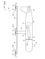
- FIG. 1 is a top view schematically showing the configuration of an electric vertical take-off and landing aircraft equipped with a control device
- FIG. 2 is a side view schematically showing the configuration of the electric vertical take-off and landing aircraft
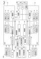
- FIG. 3 is a block diagram showing the configuration of an electric vertical take-off and landing aircraft
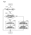
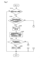
- FIG. 4 is a flowchart showing the procedure of processing in the control device of the first embodiment
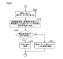
- FIG. 5 is a flowchart showing the procedure of processing in the control device of the second embodiment
- FIG. 1 is a top view schematically showing the configuration of an electric vertical take-off and landing aircraft equipped with a control device
- FIG. 2 is a side view schematically showing the configuration of the electric vertical take-off and landing aircraft
- FIG. 3 is a block diagram showing the configuration of an electric vertical take-off and landing aircraft
- FIG. 4 is a flowchart showing the procedure of processing in the control device of the first embodiment
- FIG. 5 is a flowchart showing the procedure of processing in the control device of the second embodiment
- FIG. 6 is a flowchart showing the procedure of processing when the detection value of the control sensor is out of the normal range in the control device of the second embodiment
- FIG. 7 is a flowchart showing the procedure of processing in the control device of the third embodiment
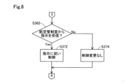
- FIG. 8 is a flowchart showing the procedure of processing when the air traffic control room does not permit the change of the flight route in the control device of the third embodiment
- FIG. 9 is a flowchart showing the procedure of processing in the control device of the fourth embodiment
- FIG. 10 is a flow chart showing the procedure of processing in the control device of the fifth embodiment.
- eVTOL electric Vertical Take-Off and Landing aircraft
- the eVTOL 100 is configured as a manned aircraft that is driven by electricity and can take off and land vertically.
- the eVTOL 100 includes the airframe 20, the plurality of rotors 30, the plurality of electric propulsion devices 10, the battery 40 shown in FIG. , a notification unit 66 and a magnetic field sensor 70 .
- the eVTOL 100 of this embodiment includes eight rotors 30 and eight electric propulsion devices 10, respectively.
- FIG. 3 representatively shows two rotors 30 and electric propulsion devices 10 out of the eight rotors 30 and electric propulsion devices 10 provided in the eVTOL 100 .
- the airframe 20 corresponds to the portion of the eVTOL 100 excluding the eight rotors 30 and the electric propulsion device 10 .
- the fuselage 20 includes a fuselage body portion 21 , a strut portion 22 , six first support portions 23 , six second support portions 24 , a main wing 25 and a tail 28 .
- the fuselage main body 21 constitutes the fuselage portion of the eVTOL 100.
- the fuselage main body 21 has a symmetrical configuration with the fuselage axis AX as an axis of symmetry.
- the “fuselage axis AX” means an axis passing through the center of gravity position CM of the fuselage and along the longitudinal direction of the eVTOL 100 .
- the "aircraft center of gravity position CM” means the position of the center of gravity of the eVTOL 100 at the time of empty weight with no crew on board.
- a passenger compartment (not shown) is formed inside the fuselage main body 21 .
- an acceleration sensor 29 is mounted on the body body 21 .
- the acceleration sensor 29 is composed of a triaxial sensor and detects acceleration of the eVTOL 100 .
- a detection result by the acceleration sensor 29 is output to the control device 50 .
- the strut part 22 has a substantially columnar external shape extending in the vertical direction, and is fixed to the upper part of the airframe body part 21 .
- the strut part 22 is arranged at a position overlapping the center-of-gravity position CM of the eVTOL 100 when viewed in the vertical direction.
- One ends of the six first support portions 23 are fixed to the upper end portion of the strut portion 22 .
- the six first support portions 23 each have a substantially rod-like external shape, and are radially arranged at equal angular intervals so as to extend along a plane perpendicular to the vertical direction.
- a rotor 30 and an electric propulsion device 10 are arranged at the other end of each first support portion 23 , that is, at the end located away from the strut portion 22 .
- Each of the six second support portions 24 has a substantially rod-like external shape, and connects the other ends (the ends not connected to the strut portions 22) of the first support portions 23 adjacent to each other. ing.
- the main wing 25 is composed of a right wing 26 and a left wing 27.
- the right wing 26 is formed so as to extend rightward from the fuselage main body 21 .
- the left wing 27 is formed extending leftward from the airframe main body 21 .
- One rotor 30 and one electric propulsion device 10 are arranged on each of the right wing 26 and the left wing 27 .
- the tail 28 is formed at the rear end of the fuselage main body 21 .
- each rotor 30 Six of the eight rotors 30 are arranged at the end of each second support portion 24 and configured as lift rotors 31 mainly for obtaining lift of the airframe 20 . Two of the eight rotors 30 are arranged on the right wing 26 and the left wing 27 respectively, and are mainly configured as cruise rotors 32 for obtaining thrust of the airframe 20 . Each rotor 30 is rotationally driven independently of each other around its respective rotation axis. Each rotor 30 has three blades 33 arranged at equal angular intervals. In this embodiment, the blade angle of each rotor 30 is configured to be variable. Specifically, the blade angle is adjusted by an actuator (not shown) according to instructions from the control device 50 . As shown in FIG.
- each rotor 30 is provided with a rotational speed sensor 34 and a torque sensor 35, respectively.
- a rotation speed sensor 34 detects the rotation speed of the rotor 30 .
- Torque sensor 35 detects the rotational torque of rotor 30 . Detection results by the sensors 34 and 35 are output to the control device 50 .
- the eight electric propulsion devices 10 shown in FIG. 1 are configured as drive devices for rotationally driving the respective rotors 30 .
- Six of the eight electric propulsion devices 10 rotate lift rotors 31 respectively.
- Two of the eight electric propulsion devices 10 rotationally drive the cruise rotors 32 respectively.
- each electric propulsion device 10 includes a drive unit 11, a drive motor 12, a gear box 13, a rotation speed sensor 14, a current sensor 15, a voltage sensor 16, and a torque sensor 17.
- sensors provided in the electric propulsion device 10 and detecting values of parameters related to the outputs of the electric propulsion device 10 are also collectively referred to as "control sensors.”
- the drive unit 11 is configured as an electronic device including an inverter circuit (not shown) and a controller (not shown) that controls the inverter circuit.
- the inverter circuit is composed of power elements such as IGBTs (Insulated Gate Bipolar Transistors) and MOSFETs (Metal-Oxide-Semiconductor Field-Effect Transistors). Provides drive voltage.
- the controller is electrically connected to the control device 50 and supplies control signals to the inverter circuit according to commands from the control device 50 .
- the drive motor 12 is configured by a brushless motor in this embodiment, and outputs rotational motion according to the voltage and current supplied from the inverter circuit of the drive section 11 .
- Any motor such as an induction motor or a reluctance motor may be used instead of the brushless motor.
- the gearbox 13 physically connects the drive motor 12 and the rotor 30 .
- the gear box 13 has a plurality of gears (not shown), decelerates the rotation of the drive motor 12 , and transmits it to the rotor 30 .
- the gear box 13 may be omitted and the rotating shaft of the rotor 30 may be directly connected to the drive motor 12 .
- the rotational speed sensor 14 and the torque sensor 17 are provided in the drive motor 12, respectively, and detect the rotational speed and rotational torque of the drive motor 12, respectively.
- a current sensor 15 and a voltage sensor 16 are provided between the driving section 11 and the driving motor 12, respectively, and detect a driving current and a driving voltage, respectively. The results of detection by the sensors 14 to 17 are output to the control device 50 via the driving section 11. FIG.
- the battery 40 is composed of a lithium ion battery and functions as one of the power supply sources in the eVTOL 100.
- the battery 40 mainly supplies electric power to the drive unit 11 of each electric propulsion device 10 to drive each drive motor 12 .
- any secondary battery such as a nickel-metal hydride battery may be used.
- a supply may be on board.
- the converter 42 is connected to the battery 40 , steps down the voltage of the battery 40 , and supplies it to the auxiliary equipment (not shown) provided in the eVTOL 100 and the control device 50 .
- the distributor 44 distributes the voltage of the battery 40 to the drive units 11 included in each electric propulsion device 10 . Note that the distributor 44 may be omitted by providing each electric propulsion device 10 with a power supply source such as the battery 40 .
- the control device 50 is a microcomputer including a storage section 51 and a CPU (Central Processing Unit), and is configured as an ECU (Electronic Control Unit).
- the storage unit 51 has ROM (Read Only Memory) and RAM (Random Access Memory).
- the CPU functions as a control unit 52 that controls the overall operation of the eVTOL 100 by executing a control program pre-stored in the storage unit 51 .
- the overall operation of the eVTOL 100 includes, for example, vertical take-off and landing operations, flight operations, and functional test execution operations for each electric propulsion device 10 .
- Vertical take-off and landing operations and flight operations may be performed based on the set air route information, may be performed by the crew's control, and may be performed based on commands from an external control unit 510 provided in the external device 500 described later. may be performed.
- the control unit 52 controls the rotation speed and rotation direction of the driving motor 12 of each electric propulsion device 10, the blade angle of each rotor 30, and the like.
- the body communication unit 64 has a function of performing wireless communication, transmits and receives information between the external communication unit 520 provided in the external device 500 and the eVTOL 100, and is configured to be able to communicate with the control device 50.
- wireless communication for example, VHF (Very High Frequency) wireless communication for private use, 4G (fourth generation mobile communication system), 5G (fifth generation mobile communication system), etc.
- Communication, wireless LAN communication according to the IEEE802.11 standard, and the like correspond to this.
- USB Universal Serial Bus
- wired communication conforming to the IEEE802.3 standard may be used.
- the external device 500 corresponds to, for example, a computer for management and control such as a server device that controls functional tests and records test results.
- a management and control computer may be, for example, a server device located in an air traffic control room, or a personal computer brought into the operation site of the eVTOL 100 by a maintenance worker who performs maintenance and inspections including function tests. may be
- the notification unit 66 performs notification according to instructions from the control device 50 .
- the notification unit 66 is configured by a display device mounted in the passenger compartment to display characters, images, etc., a speaker for outputting voices, warning sounds, etc., and the like. inform information.
- the magnetic field sensor 70 is installed in the eVTOL 100 and detects the strength of the magnetic field.
- the magnetic field sensor 70 is preferably a sensor capable of detecting a magnetic field with higher sensitivity than the control sensor.
- one magnetic field sensor 70 is installed in the lower part of the airframe 20 .
- A-2. Processing by the control device 50 By executing the process shown in FIG. 4, the control device 50 executes a corresponding process according to the magnetic field when the strength of the magnetic field detected by the magnetic field sensor 70 is equal to or greater than the set value.
- the processing shown in FIG. 4 is repeatedly executed in the control device 50 when the eVTOL 100 is activated.
- the corresponding processing is predetermined processing for the eVTOL 100 itself or another eVTOL 100 to fly according to a magnetic field having a strength equal to or greater than a set value.
- step S110 the control device 50 determines whether or not the strength of the magnetic field detected by the magnetic field sensor 70 is equal to or greater than a preset threshold.
- the threshold value is a value specified in advance by experiments or the like as the strength of the magnetic field that can cause the detection value of the control sensor to be outside the normal range. If the strength of the magnetic field is smaller than the threshold (step S110: No), the control device 50 terminates this process. If the strength of the magnetic field is equal to or greater than the threshold (step S110: Yes), after the preset waiting time has elapsed, the control device 50 checks whether the detected value of the control sensor is within the preset normal range. A determination is made (step S120).
- the reason why it is determined whether or not the detection value of the control sensor is within a preset normal range after the standby time has passed is that if the change in the detection value of the control sensor due to the magnetic field is instantaneous, the control of the eVTOL 100 can be performed. This is because the influence is small, so there is no need to notify the abnormality occurrence information, which will be described later.
- the standby time varies depending on the flight conditions of the eVTOL 100 . For example, the standby time in the horizontal flight state in this embodiment is about 1 second, but since more stable control is required during the vertical takeoff and landing operation, the control sensor detects the control sensor in a shorter standby time than in the horizontal flight state. It is necessary to determine whether the value is within the normal range.
- Magnetic field-related information means information about a magnetic field.
- the magnetic field-related information includes at least coordinates at which a magnetic field having a strength equal to or greater than the threshold value is detected in this embodiment.
- the magnetic field related information may include the time when the magnetic field above the threshold was detected and the strength of the detected magnetic field.
- a pilot may exercise control of the eVTOL 100 based on magnetic field-related information. Based on the magnetic field-related information, the air traffic control room can alert other aircraft to the magnetic field.
- step S120 if the detected value of the control sensor is outside the preset normal range (step S120: No), the control device 50, as a corresponding process, notifies the pilot of the magnetic field-related information and the abnormality occurrence information ( Step S132) and transmission of the magnetic field-related information and the abnormality occurrence information to the air traffic control room (step S142) are executed, and this process is terminated.
- "Abnormality occurrence information” means information related to abnormalities caused by magnetic fields.
- Magnetic field anomaly means a situation in which an anomaly in the detection value of the control sensor continues even after the standby time has elapsed, and normal control of the eVTOL 100 may be hindered.
- the abnormality occurrence information includes at least information as to in which electric propulsion device 10 among the plurality of electric propulsion devices 10 an abnormality due to a magnetic field has occurred.
- the abnormality occurrence information may include the time when the abnormality occurred in the electric propulsion device 10 .
- a pilot can exercise control of the eVTOL 100 based on magnetic field-related information and anomaly occurrence information. Based on the magnetic field-related information and the abnormal occurrence information, the air traffic control room can alert other aircraft about the magnetic field.
- the control device 50 of the first embodiment described above when the strength of the magnetic field detected by the magnetic field sensor 70 is equal to or greater than the preset threshold value, the pilot is notified of the magnetic field-related information and air traffic control is performed. Make a call to the room.
- the detected value of the control sensor is out of the preset normal range, in addition to the magnetic field-related information, abnormal occurrence information is notified to the pilot and transmitted to the air traffic control room. For this reason, depending on the magnetic field and the abnormality caused by the magnetic field, it is possible to execute control such as changing the flight route of the eVTOL 100 and emergency landing, so it becomes easier to avoid environments where strong magnetic fields and electric fields are generated. It is possible to suppress the decline in sexuality.
- since it is possible to alert other aircraft about the magnetic field via the air traffic control room it is possible to suppress the deterioration of the flight stability of the other aircraft.
- the eVTOL 100 of the second embodiment is configured as an unmanned aerial vehicle.
- the control device 50 of the second embodiment transmits magnetic field-related information and abnormality occurrence information to the air traffic control room, receives instructions from the air traffic control room, and executes control of the eVTOL 100. It differs from the control device 50 of the first embodiment in that the The device configuration of the eVTOL 100 of the second embodiment and other procedures in the processing by the control device 50 are the same as those of the eVTOL 100 of the first embodiment. Detailed description is omitted.
- step S240 when the control device 50 transmits the magnetic field-related information to the air traffic control room in the above-described step S130, and then does not receive an instruction from the air traffic control room within a predetermined time (step S240: No), The controller 50 requests instructions from the air traffic control room (step S252) and waits for instructions from the air traffic control room again. If an instruction from the air traffic control room has been received (step S240: Yes), the control device 50 executes control of the eVTOL 100 according to the received instruction as a corresponding process (step S250), and ends this process.
- the "flight mode corresponding to an abnormality" means that some of the electric propulsion devices 10 including the electric propulsion device 10 in which an abnormality has occurred are stopped and the flight is continued. and/or searching for a possible landing point and landing the eVTOL 100.
- step S242 in addition to the magnetic field-related information and the abnormality occurrence information, the control device 50 notifies the air traffic control room that the flight mode has been switched to the one corresponding to the abnormality due to the occurrence of an abnormality due to the magnetic field.
- control device 50 When receiving an instruction from the air traffic control room (step S252: Yes), the control device 50 controls the eVTOL 100 according to the instruction (step S262), and ends this process.
- step S252 if no instruction is received from the air traffic control room (step S252: No), the control device 50 continues to control the eVTOL 100 in the flight mode corresponding to the abnormality (step S264), and terminates this process. .
- the control device 50 of the second embodiment described above the same effects as the control device 50 of the first embodiment are obtained.
- the control device 50 can execute control of the eVTOL 100 according to information regarding a wider range of magnetic fields based on information transmitted from other eVTOLs 100 to the air traffic control room. It becomes easier to avoid environments in which magnetic fields and electric fields are generated, and it is possible to further suppress deterioration in the flight stability of the eVTOL 100 .
- the flight mode is shifted to a flight mode corresponding to the abnormality to maintain safe flight. Therefore, it is possible to suppress a decrease in the safety of the eVTOL 100 when an abnormality occurs.
- the eVTOL 100 of the third embodiment is configured as an unmanned aerial vehicle. As shown in FIGS. 7 and 8, the control device 50 of the third embodiment differs from the control device 50 of the second embodiment in that the processes from step S330 to step S374 are performed after step S120.
- the device configuration of the eVTOL 100 of the third embodiment and other procedures in the processing by the control device 50 are the same as those of the eVTOL 100 of the second embodiment. Detailed description is omitted.
- the control device 50 recalculates the flight route based on the magnetic field-related information as a corresponding process (step S330). After that, the control device 50 transmits the information about the new flight route obtained by the recalculation together with the magnetic field-related information to the air traffic control room (step S340), and requests permission to change the flight route to the new flight route.
- step S350 When the air traffic control room permits the flight route change (step S350: Yes), the control device 50 changes the flight route to a new flight route (step S360) and ends the process.
- step S350: No when the flight route change is not permitted from the air traffic control room (step S350: No), and as shown in FIG. 8, when an instruction is received from the air traffic control room (step S362: Yes) , the control device 50 executes control of the eVTOL 100 according to an instruction from the air traffic control room as a corresponding process (step S372), and ends this process. If no instruction is received from the air traffic control room (step S362: No), the control device 50 ends this process without changing the control of the eVTOL 100 (step S374).
- control device 50 of the third embodiment the same effects as those of the control device 50 of the second embodiment are obtained.
- control device 50 transmits a new flight route recalculated according to the magnetic field to the air traffic control room, and changes the flight route to the new flight route with permission. It becomes easier to avoid, and the deterioration of the flight stability of the eVTOL 100 can be further suppressed.
- the eVTOL 100 of the fourth embodiment is configured as an unmanned aerial vehicle. As shown in FIG. 9, the controller 50 of the fourth embodiment differs from the controller 50 of the first embodiment in that it controls the eVTOL 100 only according to instructions from the air traffic control room. Since the device configuration of the eVTOL 100 of the fourth embodiment and other procedures in the processing by the control device 50 are the same as those of the eVTOL 100 of the first embodiment, the same configurations and the same procedures are denoted by the same reference numerals. Detailed description is omitted.
- step S120 When the detection value of the control sensor is within the normal range in step S120 described above, the control device 50 executes the process of step S140 described above. If the detected value of the control sensor is out of the normal range, the control device 50 executes the process of step S142 described above.
- control device 50 After transmitting the information to the air traffic control room, the control device 50 executes the processing from step S362 to step S374 shown in FIG.
- control device 50 of the fourth embodiment the same effects as those of the control device 50 of the first embodiment are obtained.
- control device 50 controls the eVTOL 100 only according to instructions from the air traffic control room, it is possible to perform control according to the magnetic field and the abnormality caused by the magnetic field without requiring complicated processing in the control device 50. It is possible to suppress the deterioration of the flight stability of the eVTOL 100.
- the control device 50 of the fifth embodiment does not include the magnetic field sensor 70, and uses the magnitude of the difference between the detection value of the control sensor and the reference value to determine whether an abnormality has occurred due to the magnetic field. is different from the control device 50 of Since the device configuration of the eVTOL 100 of the fifth embodiment and other procedures in the processing by the control device 50 are the same as those of the eVTOL 100 of the first embodiment, the same configurations and the same procedures are denoted by the same reference numerals. Detailed description is omitted.
- the control device 50 calculates the magnitude of the difference between the detection value of the control sensor and a preset reference value.
- the reference value is set in advance in the storage unit 51 as a detection value of the control sensor in normal times. For example, in a configuration in which the control sensor detects the number of revolutions of the drive motor 12, the average number of revolutions of the drive motor 12 during normal operation is set as a reference value for each flight mode, such as vertical take-off and landing mode and horizontal flight mode, and for each flight altitude. may be
- step S515: No If the magnitude of the calculated difference is smaller than the preset first threshold (step S515: No), the control device 50 terminates this process. If the calculated magnitude of the difference is equal to or greater than the preset first threshold (step S515: Yes), the control device 50 waits for a preset standby time after the previous calculation of the difference, The magnitude of the difference between the detection value of the control sensor and the reference value is calculated again (step S520). The reason why the magnitude of the difference between the detection value of the control sensor and the reference value is calculated again after the standby time has elapsed is that if the change in the detection value of the control sensor due to the magnetic field is instantaneous, the effect on the control of the eVTOL 100 is small. , there is no need to notify the abnormality occurrence information.
- step S525: Yes When the magnitude of the difference calculated again is equal to or greater than the preset second threshold (step S525: Yes), the control device 50 executes the above-described steps S130 and S140 as the corresponding processing, End the process.
- step S525: No When the magnitude of the difference calculated again is smaller than the preset second threshold value (step S525: No), the control device 50 executes the above-described steps S132 and S142 as the corresponding processing, and performs the main processing. exit. Note that in the present embodiment, the second threshold is greater than or equal to the first threshold.
- control device 50 of the fifth embodiment the same effects as the control device 50 of the first embodiment are obtained.
- manufacturing cost of the eVTOL 100 can be suppressed because the magnetic field sensor 70 is not required to determine the strength of the magnetic field that may cause a difference between the output value of the control sensor and the reference value.
- one magnetic field sensor 70 is installed in the lower part of the airframe 20, but the present disclosure is not limited to this.
- the magnetic field sensor 70 may be installed inside the plurality of electric propulsion devices 10 for each electric propulsion device 10 .
- the control device 50 can detect the direction in which the magnetic field is generated and the effect of the magnetic field on each electric propulsion device 10 .
- the control device 50 transmits the magnetic field-related information and the abnormality occurrence information to the air traffic control room, but the present disclosure is not limited to this.
- the controller 50 may directly transmit magnetic field-related information and anomaly occurrence information to aircraft flying in the vicinity. According to such a configuration, it is possible to alert the other aircraft about the magnetic field in a shorter time than sending the magnetic field-related information and the abnormality occurrence information to the other aircraft via the air traffic control room. .
- control device 50 transmits the magnetic field-related information and the abnormality occurrence information to the air traffic control room, but the present disclosure is not limited to this.
- the control device 50 may record the magnetic field-related information and the abnormality occurrence information in the storage section 51 . According to this configuration, by recording the magnetic field-related information and the abnormality occurrence information in the storage unit 51, the time required for checking the eVTOL 100 after landing can be shortened.
- control device 50 receives instructions from the air traffic control room and executes control of the eVTOL 100, but the present disclosure is not limited to this.
- the control device 50 may control the eVTOL 100 in response to a warning or the like directly transmitted from another aircraft flying nearby.
- the pilot can control the eVTOL 100 based on the magnetic field-related information and the abnormality occurrence information, but the present disclosure is not limited to this.
- the control device 50 may forcibly execute preset control based on the magnetic field-related information and the abnormality occurrence information.
- control device 50 determines whether or not the detected value of the control sensor is within the normal range after the standby time has passed after it is determined that the strength of the detected magnetic field is equal to or greater than the threshold. but the present disclosure is not limited thereto. The control device 50 may determine whether or not the detected value of the control sensor is within the normal range immediately after it is determined that the strength of the detected magnetic field is equal to or greater than the threshold.
- control device 50 performs determination using the second threshold after the standby time has passed after determination using the first threshold, but the present disclosure is not limited to this.
- the control device 50 may perform the determination using the second threshold immediately after the determination using the first threshold.
- the controller and techniques described in this disclosure may be implemented by a dedicated computer provided by configuring a processor and memory programmed to perform one or more functions embodied by the computer program.
- the controls and techniques described in this disclosure may be implemented by a dedicated computer provided by configuring the processor with one or more dedicated hardware logic circuits.
- the controller and techniques described in this disclosure can be implemented by a combination of a processor and memory programmed to perform one or more functions and a processor configured by one or more hardware logic circuits. It may also be implemented by one or more dedicated computers configured.
- the computer program may also be stored as computer-executable instructions on a computer-readable non-transitional tangible recording medium.
Landscapes
- Engineering & Computer Science (AREA)
- Aviation & Aerospace Engineering (AREA)
- Mechanical Engineering (AREA)
- Chemical & Material Sciences (AREA)
- Combustion & Propulsion (AREA)
- Radar, Positioning & Navigation (AREA)
- Remote Sensing (AREA)
- Physics & Mathematics (AREA)
- General Physics & Mathematics (AREA)
- Automation & Control Theory (AREA)
- Control Of Position, Course, Altitude, Or Attitude Of Moving Bodies (AREA)
- Traffic Control Systems (AREA)
Abstract
制御装置(50)は、電動垂直離着陸機(100)の制御装置であって、電動垂直離着陸機が備える磁場センサ(70)により検出された磁場の強さが予め設定された閾値以上である場合に、電動垂直離着陸機または他の電動垂直離着陸機が磁場に応じた飛行を行うための予め定められた対応処理を実行する。
Description
本出願は、2021年12月23日に出願された日本出願番号2021-208996号に基づくもので、ここにその記載内容を援用する。
本開示は、電動垂直離着陸機の制御装置に関する。
近年、ガスタービンエンジンを有する飛行機とは異なる種類の航空機として、電動垂直離着陸機(eVTOL:electric Vertical Take-Off and Landing aircraft)と呼ばれる有人または無人の航空機の開発が活発化している。電動垂直離着陸機は、モータを有する電動推進装置を複数備え、複数のモータによって複数の回転翼が回転駆動されることで、機体の揚力や推力を得ている。複数の電動推進装置は、電動推進装置の出力に関する値を検出するセンサや回路をそれぞれ備えているため、電動垂直離着陸機は、従来の航空機より磁場や電場の影響を受けやすい。特許文献1には、航空機における落雷検出用の電子回路が記載されている。
特許文献1に記載の落雷検出回路は、航空機において落雷があったことを検出しパイロット等への警告を行うが、電動推進装置は従来の航空機より磁場や電場の影響を受けやすいため、強い磁場や電場が発生する環境は回避した方がより安全である。
本開示は、以下の形態として実現することが可能である。
本開示の一形態によれば、電動垂直離着陸機の制御装置が提供される。この制御装置は、電動垂直離着陸機の制御装置であって、前記電動垂直離着陸機が備える磁場センサにより検出された磁場の強さが予め設定された閾値以上である場合に、前記電動垂直離着陸機または他の前記電動垂直離着陸機が前記磁場に応じた飛行を行うための予め定められた対応処理を実行する。
この形態の制御装置によれば、磁場センサにより検出された磁場に応じて電動垂直離着陸機の制御を実行するため、強い磁場や電場が発生する環境を回避しやすくなり、電動垂直離着陸機の飛行安定性の低下を抑制できる。
この形態の制御装置によれば、磁場センサにより検出された磁場に応じて電動垂直離着陸機の制御を実行するため、強い磁場や電場が発生する環境を回避しやすくなり、電動垂直離着陸機の飛行安定性の低下を抑制できる。
本開示は、種々の形態で実現することも可能である。例えば、制御装置を備える電動垂直離着陸機、電動垂直離着陸機の制御方法等の形態で実現することができる。
本開示についての上記目的およびその他の目的、特徴や利点は、添付の図面を参照しながら下記の詳細な記述により、より明確になる。その図面は、
図1は、制御装置を搭載した電動垂直離着陸機の構成を模式的に示す上面図であり、
図2は、電動垂直離着陸機の構成を模式的に示す側面図であり、
図3は、電動垂直離着陸機の構成を示すブロック図であり、
図4は、第1実施形態の制御装置における処理の手順を示すフローチャートであり、
図5は、第2実施形態の制御装置における処理の手順を示すフローチャートであり、
図6は、第2実施形態の制御装置において制御センサの検出値が正常範囲外である場合の処理の手順を示すフローチャートであり、
図7は、第3実施形態の制御装置における処理の手順を示すフローチャートであり、
図8は、第3実施形態の制御装置において航空管制室が飛行ルートの変更を許可しない場合の処理の手順を示すフローチャートであり、
図9は、第4実施形態の制御装置における処理の手順を示すフローチャートであり、
図10は、第5実施形態の制御装置における処理の手順を示すフローチャートである。
A.第1実施形態:
A-1.装置構成:
図1および図2に示すように、本開示の一実施形態としての制御装置50は、電動垂直離着陸機100(以下、「eVTOL(electric Vertical Take-Off and Landing aircraft)100」とも呼ぶ)に搭載されて、eVTOL100の動作を制御する。
A-1.装置構成:
図1および図2に示すように、本開示の一実施形態としての制御装置50は、電動垂直離着陸機100(以下、「eVTOL(electric Vertical Take-Off and Landing aircraft)100」とも呼ぶ)に搭載されて、eVTOL100の動作を制御する。
eVTOL100は、電気により駆動され、鉛直方向に離着陸可能な有人航空機として構成されている。eVTOL100は、制御装置50に加えて、機体20と、複数のロータ30と、複数の電動推進装置10と、図3に示すバッテリ40と、コンバータ42と、分配器44と、機体通信部64と、報知部66と、磁場センサ70とを備えている。図1に示すように、本実施形態のeVTOL100は、ロータ30と電動推進装置10とをそれぞれ8つずつ備えている。なお、図3では、図示の便宜上、eVTOL100が備える8つのロータ30および電動推進装置10のうち、2つのロータ30および電動推進装置10を代表して示している。
図1および図2に示すように、機体20は、eVTOL100において8つのロータ30および電動推進装置10を除いた部分に相当する。機体20は、機体本体部21と、支柱部22と、6つの第1支持部23と、6つの第2支持部24と、主翼25と、尾翼28とを備える。
機体本体部21は、eVTOL100の胴体部分を構成する。機体本体部21は、機体軸AXを対称軸として左右対称の構成を有する。本実施形態において、「機体軸AX」とは、機体重心位置CMを通り、eVTOL100の前後方向に沿った軸を意味している。また、「機体重心位置CM」とは、乗員が搭乗していない空虚重量時におけるeVTOL100の重心位置を意味している。機体本体部21の内部には、図示しない乗員室が形成されている。また、機体本体部21には、加速度センサ29が搭載されている。加速度センサ29は、三軸センサにより構成され、eVTOL100の加速度を検出する。加速度センサ29による検出結果は、制御装置50へと出力される。
支柱部22は、鉛直方向に延びる略柱状の外観形状を有し、機体本体部21の上部に固定されている。本実施形態において、支柱部22は、鉛直方向に見てeVTOL100の機体重心位置CMと重なる位置に配置されている。支柱部22の上端部には、6つの第1支持部23の一方の端部がそれぞれ固定されている。6つの第1支持部23は、それぞれ略棒状の外観形状を有し、鉛直方向に垂直な面に沿って延びるように、互いに等角度間隔で放射状に配置されている。各第1支持部23の他方の端部、すなわち支柱部22から遠ざかる位置にある端部には、それぞれロータ30と電動推進装置10とが配置されている。6つの第2支持部24は、それぞれ略棒状の外観形状を有し、互いに隣り合う第1支持部23の他方の端部(支柱部22と接続されていない側の端部)同士を接続している。
主翼25は、右翼26と左翼27とにより構成されている。右翼26は、機体本体部21から右方向に延びて形成されている。左翼27は、機体本体部21から左方向に延びて形成されている。右翼26と左翼27とには、それぞれロータ30と電動推進装置10とが1つずつ配置されている。尾翼28は、機体本体部21の後端部に形成されている。
8つのロータ30のうちの6つは、各第2支持部24の端部に配置され、主に機体20の揚力を得るためのリフト用ロータ31として構成されている。8つのロータ30のうちの2つは、右翼26と左翼27とにそれぞれ配置され、主に機体20の推力を得るためのクルーズ用ロータ32として構成されている。各ロータ30は、それぞれの回転軸を中心として、互いに独立して回転駆動される。各ロータ30は、互いに等角度間隔で配置された3つのブレード33をそれぞれ有する。本実施形態において、各ロータ30のブレード角は、それぞれ可変に構成されている。具体的には、制御装置50からの指示に従い図示しないアクチュエータによってブレード角が調整される。図3に示すように、各ロータ30には、回転数センサ34と、トルクセンサ35とがそれぞれ設けられている。回転数センサ34は、ロータ30の回転数を検出する。トルクセンサ35は、ロータ30の回転トルクを検出する。各センサ34、35による検出結果は、制御装置50へと出力される。
図1に示す8つの電動推進装置10は、各ロータ30をそれぞれ回転駆動させるための駆動装置として構成されている。8つの電動推進装置10のうちの6つは、それぞれリフト用ロータ31を回転駆動させる。8つの電動推進装置10のうちの2つは、それぞれクルーズ用ロータ32を回転駆動させる。
図3に示すように、各電動推進装置10は、駆動部11と、駆動用モータ12と、ギアボックス13と、回転数センサ14と、電流センサ15と、電圧センサ16と、トルクセンサ17とを有する。以下、電動推進装置10が備え、10の出力に関連するパラメータの値を検出するセンサを総称して、「制御センサ」とも呼ぶ。
駆動部11は、図示しないインバータ回路と、かかるインバータ回路を制御する図示しないコントローラとを含む電子機器として構成されている。インバータ回路は、IGBT(Insulated Gate Bipolar Transistor)やMOSFET(Metal-Oxide-Semiconductor Field-Effect Transistor)等のパワー素子により構成され、コントローラから供給される制御信号に応じたデューティ比により駆動用モータ12に駆動電圧を供給する。コントローラは、制御装置50と電気的に接続されており、制御装置50からの指令に応じてインバータ回路に制御信号を供給する。
駆動用モータ12は、本実施形態ではブラシレスモータにより構成され、駆動部11のインバータ回路から供給される電圧および電流に応じた回転運動を出力する。なお、ブラシレスモータに代えて、誘導モータやリラクタンスモータ等の任意のモータにより構成されていてもよい。
ギアボックス13は、駆動用モータ12とロータ30とを物理的に接続している。ギアボックス13は、図示しない複数のギアを有し、駆動用モータ12の回転を減速してロータ30へと伝達する。なお、ギアボックス13が省略されて駆動用モータ12にロータ30の回転軸が直接的に接続されていてもよい。
回転数センサ14とトルクセンサ17とは、それぞれ駆動用モータ12に設けられており、駆動用モータ12の回転数と回転トルクとをそれぞれ検出する。電流センサ15と電圧センサ16とは、それぞれ駆動部11と駆動用モータ12との間に設けられており、駆動電流と駆動電圧とをそれぞれ検出する。各センサ14~17による検出結果は、駆動部11を介して制御装置50へと出力される。
バッテリ40は、リチウムイオン電池により構成され、eVTOL100における電力供給源の1つとして機能する。バッテリ40は、主に、各電動推進装置10がそれぞれ有する駆動部11へと電力を供給して各駆動用モータ12を駆動させる。なお、リチウムイオン電池に代えて、ニッケル水素電池等の任意の二次電池により構成されていてもよく、バッテリ40に代えて、またはバッテリ40に加えて、燃料電池や発電機等の任意の電力供給源が搭載されていてもよい。
コンバータ42は、バッテリ40と接続されており、バッテリ40の電圧を降圧してeVTOL100が備える図示しない補機類や制御装置50へと供給する。分配器44は、バッテリ40の電圧を各電動推進装置10が備える駆動部11へと分配する。なお、各電動推進装置10がバッテリ40等の電力供給源をそれぞれ備えることにより、分配器44が省略されてもよい。
制御装置50は、記憶部51とCPU(Central Processing Unit)とを備えるマイクロコンピュータであり、ECU(Electronic Control Unit)として構成されている。記憶部51は、ROM(Read Only Memory)とRAM(Random Access Memory)とを有する。CPUは、記憶部51に予め記憶されている制御プログラムを実行することにより、eVTOL100の全体動作を制御する制御部52として機能する。
eVTOL100の全体動作としては、例えば、垂直離着陸動作、飛行動作や、各電動推進装置10の機能試験の実行動作等が該当する。垂直離着陸動作および飛行動作は、設定された航空経路情報に基づいて実行されてもよく、乗員の操縦により実行されてもよく、後述する外部装置500が備える外部制御部510からの指令に基づいて実行されてもよい。制御部52は、eVTOL100の動作において、各電動推進装置10が有する駆動用モータ12の回転数および回転方向や、各ロータ30のブレード角等を制御する。
機体通信部64は、無線通信を行なう機能を有し、外部装置500が備える外部通信部520とeVTOL100との間で情報の送受信を行なうとともに、制御装置50と通信可能に構成されている。無線通信としては、例えば、民間用VHF(Very High Frequency)無線通信や、4G(第4世代移動体通信システム)や5G(第5世代移動体通信システム)等の電気通信事業者が提供する無線通信や、IEEE802.11規格に従った無線LAN通信等が該当する。また、例えば、USB(Universal Serial Bus)や、IEEE802.3規格に従った有線通信であってもよい。なお、外部装置500としては、例えば、機能試験の制御や試験結果の記録等を行うサーバ装置等の管理および制御用のコンピュータが該当する。かかる管理・制御用コンピュータは、例えば、航空管制室に配置されているサーバ装置であってもよく、また、機能試験を含む保守や点検を行う保守作業員がeVTOL100の運用場所に持ち込んだパーソナルコンピュータであってもよい。
報知部66は、制御装置50からの指示に従って報知を行う。本実施形態において、報知部66は、乗員室に搭載されて文字や画像等を表示する表示装置や、音声や警告音等を出力するスピーカ等により構成され、視覚情報や聴覚情報によって乗員に各種情報を報知する。
磁場センサ70は、eVTOL100に設置され、磁場の強さの検出を行う。磁場センサ70は、制御センサよりも感度よく磁場を検出可能なセンサであることが好ましい。本実施形態においては、磁場センサ70は、機体20の下部に1つ設置されている。
A-2.制御装置50による処理:
制御装置50は、図4に示す処理を実行することにより、磁場センサ70により検出された磁場の強さが設定値以上の場合に、磁場に応じた対応処理を実行する。図4に示す処理は、eVTOL100が起動されると、制御装置50において繰り返し実行される。対応処理とは、自らまたは他のeVTOL100が、設定値以上の強さの磁場に応じた飛行を行うための処理であり、予め定められている。
制御装置50は、図4に示す処理を実行することにより、磁場センサ70により検出された磁場の強さが設定値以上の場合に、磁場に応じた対応処理を実行する。図4に示す処理は、eVTOL100が起動されると、制御装置50において繰り返し実行される。対応処理とは、自らまたは他のeVTOL100が、設定値以上の強さの磁場に応じた飛行を行うための処理であり、予め定められている。
ステップS110において、制御装置50は、磁場センサ70により検出された磁場の強さが、予め設定された閾値以上か否かの判定を行う。なお、閾値は、制御センサの検出値が正常範囲外となりうる磁場の強さとして、予め実験等により特定された値である。磁場の強さが閾値より小さい場合(ステップS110:No)、制御装置50は、本処理を終了する。磁場の強さが閾値以上の場合(ステップS110:Yes)、予め設定された待機時間の経過後、制御装置50は、制御センサの検出値が予め設定された正常範囲内であるか否かの判定を行う(ステップS120)。待機時間の経過後に制御センサの検出値が予め設定された正常範囲内であるか否かの判定を行うのは、制御センサの検出値の磁場による変化が瞬間的であればeVTOL100の制御への影響は少ないため、後述する異常発生情報の通知が必要ないからである。なお、待機時間は、eVTOL100の飛行状態によって異なる。例えば、本実施形態における水平飛行状態での待機時間は1秒程度であるが、垂直離着陸動作中にはより安定した制御が必要となるため、水平飛行状態よりも短い待機時間で制御センサの検出値が正常範囲内か否かを判定する必要がある。
制御センサの検出値が予め設定された正常範囲内である場合(ステップS120:Yes)、制御装置50は、対応処理として、磁場関連情報のパイロットへの通知(ステップS130)および磁場関連情報の航空管制室への発信(ステップS140)を実行し、本処理を終了する。「磁場関連情報」とは、磁場に関する情報を意味する。磁場関連情報は、本実施形態においては、閾値以上の強さの磁場が検出された座標を少なくとも含む。磁場関連情報には、閾値以上の磁場が検出された時刻および検出された磁場の強さが含まれてもよい。パイロットは、磁場関連情報に基づいて、eVTOL100の制御を実行することができる。航空管制室は、磁場関連情報に基づいて、他の航空機に対して磁場に関する注意喚起等を行うことができる。
これに対して、制御センサの検出値が予め設定された正常範囲外である場合(ステップS120:No)、制御装置50は、対応処理として、磁場関連情報および異常発生情報のパイロットへの通知(ステップS132)および磁場関連情報および異常発生情報の航空管制室への発信(ステップS142)を実行し、本処理を終了する。「異常発生情報」とは、磁場による異常に関する情報を意味する。「磁場による異常」とは、待機時間経過後にも制御センサの検出値の異常が継続し、eVTOL100の正常な制御が妨げられるおそれがある状況を意味する。異常発生情報は、本実施形態では、複数の電動推進装置10のうちどの電動推進装置10で磁場による異常が発生しているかという情報を少なくとも含む。異常発生情報には、電動推進装置10で異常が発生した時刻が含まれてもよい。パイロットは、磁場関連情報および異常発生情報に基づいて、eVTOL100の制御を実行することができる。航空管制室は、磁場関連情報および異常発生情報に基づいて、他の航空機に対して磁場に関する注意喚起等を行うことができる。
以上説明した第1実施形態の制御装置50によれば、磁場センサ70により検出された磁場の強さが、予め設定された閾値以上である場合に、磁場関連情報のパイロットへの通知および航空管制室への発信を行う。加えて、制御センサの検出値が、予め設定された正常範囲外である場合には、磁場関連情報に加え、異常発生情報のパイロットへの通知および航空管制室への発信を行う。このため、磁場および磁場による異常に応じて、eVTOL100の飛行ルートの変更および緊急着陸等の制御を実行することができるので、強い磁場や電場が発生する環境を回避しやすくなり、eVTOL100の飛行安定性の低下を抑制できる。加えて、航空管制室を介して、他の航空機に対して磁場に関する注意喚起等を行うことができるため、他の航空機の飛行安定性の低下も抑制できる。
B.第2実施形態:
第2実施形態のeVTOL100は、無人航空機として構成されている。第2実施形態の制御装置50は、図5および図6に示すように、磁場関連情報および異常発生情報を航空管制室に発信し、航空管制室からの指示を受信してeVTOL100の制御を実行する点において、第1実施形態の制御装置50と異なっている。第2実施形態のeVTOL100の装置構成および制御装置50による処理におけるその他の手順は、第1実施形態のeVTOL100と同じであるので、同一の構成および同一の手順には同一の符号を付し、その詳細な説明を省略する。
第2実施形態のeVTOL100は、無人航空機として構成されている。第2実施形態の制御装置50は、図5および図6に示すように、磁場関連情報および異常発生情報を航空管制室に発信し、航空管制室からの指示を受信してeVTOL100の制御を実行する点において、第1実施形態の制御装置50と異なっている。第2実施形態のeVTOL100の装置構成および制御装置50による処理におけるその他の手順は、第1実施形態のeVTOL100と同じであるので、同一の構成および同一の手順には同一の符号を付し、その詳細な説明を省略する。
図5に示すように、制御装置50は、上述のステップS130において磁場関連情報を航空管制室に発信し、その後、航空管制室の指示を所定時間内に受信しない場合(ステップS240:No)、制御装置50は、航空管制室に対して指示を要請し(ステップS252)、再び航空管制室からの指示を待つ。航空管制室の指示を受信した場合(ステップS240:Yes)、制御装置50は、対応処理として、受信した指示に従ってeVTOL100の制御を実行し(ステップS250)、本処理を終了する。
上述のステップS120において制御センサの検出値が予め設定された正常範囲外である場合には、図6に示すように、制御装置50は、対応処理として、予め設定された、異常に応じた飛行モードに切り替えて(ステップS232)、eVTOL100の制御を実行する。本実施形態において、「異常に応じた飛行モード」とは、複数の電動推進装置10のうち、異常の発生した電動推進装置10を含む一部の電動推進装置10を停止して飛行を継続することと、着陸可能地点を検索しeVTOL100を着陸させることとのうち少なくともいずれかを実行するモードを意味する。
ステップS242において、制御装置50は、磁場関連情報および異常発生情報に加えて、磁場による異常発生により異常に応じた飛行モードに切り替えたことを航空管制室へ発信する。
航空管制室から指示を受信した場合(ステップS252:Yes)、制御装置50は、指示に従ってeVTOL100の制御を実行し(ステップS262)、本処理を終了する。
これに対して、航空管制室から指示を受信しない場合(ステップS252:No)、制御装置50は、引き続き異常に応じた飛行モードによるeVTOL100の制御を継続し(ステップS264)、本処理を終了する。
以上説明した第2実施形態の制御装置50によれば、第1実施形態の制御装置50と同様の効果を奏する。加えて、制御装置50は、航空管制室から指示を受けることにより、他のeVTOL100から航空管制室に発信された情報に基づいたより広範囲の磁場に関する情報に応じてeVTOL100の制御を実行できるため、強い磁場や電場が発生する環境をより回避しやすくなり、eVTOL100の飛行安定性の低下をより抑制できる。また、磁場による異常が発生した際には、異常に応じた飛行モードに移行して安全な飛行を維持するため、異常発生時におけるeVTOL100の安全性の低下を抑制できる。
C.第3実施形態:
第3実施形態のeVTOL100は、無人航空機として構成されている。図7および図8に示すように、第3実施形態の制御装置50は、ステップS120の後にステップS330からステップS374の処理を行う点において、第2実施形態の制御装置50と異なっている。第3実施形態のeVTOL100の装置構成および制御装置50による処理におけるその他の手順は、第2実施形態のeVTOL100と同じであるので、同一の構成および同一の手順には同一の符号を付し、その詳細な説明を省略する。
第3実施形態のeVTOL100は、無人航空機として構成されている。図7および図8に示すように、第3実施形態の制御装置50は、ステップS120の後にステップS330からステップS374の処理を行う点において、第2実施形態の制御装置50と異なっている。第3実施形態のeVTOL100の装置構成および制御装置50による処理におけるその他の手順は、第2実施形態のeVTOL100と同じであるので、同一の構成および同一の手順には同一の符号を付し、その詳細な説明を省略する。
上述のステップS120において制御センサの検出値が正常範囲内である場合、制御装置50は、対応処理として、磁場関連情報に基づいて飛行ルートの再計算を行う(ステップS330)。その後、制御装置50は、再計算により得られた新規飛行ルートについての情報を磁場関連情報とともに航空管制室へ発信し(ステップS340)、新規飛行ルートへの飛行ルート変更の許可を要請する。
航空管制室が飛行ルート変更を許可した場合(ステップS350:Yes)、制御装置50は、飛行ルートを新規飛行ルートに変更し(ステップS360)、処理を終了する。
これに対して、航空管制室から飛行ルート変更を許可しない場合(ステップS350:No)であって、図8に示すように、航空管制室から指示を受信した場合(ステップS362:Yes)には、制御装置50は、対応処理として、航空管制室からの指示に従ってeVTOL100の制御を実行し(ステップS372)、本処理を終了する。航空管制室から指示を受信しない場合(ステップS362:No)には、制御装置50は、eVTOL100の制御を変更することなく(ステップS374)、本処理を終了する。
以上説明した第3実施形態の制御装置50によれば、第2実施形態の制御装置50と同様の効果を奏する。加えて、制御装置50は、磁場に応じて再計算した新規飛行ルートを航空管制室に発信し、許可を得て飛行ルートを新規飛行ルートへ変更するため、強い磁場や電場が発生する環境をより回避しやすくなり、eVTOL100の飛行安定性の低下をより抑制できる。
D.第4実施形態:
第4実施形態のeVTOL100は、無人航空機として構成されている。図9に示すように、第4実施形態の制御装置50は、航空管制室からの指示のみに従って、eVTOL100の制御を実行する点において、第1実施形態の制御装置50と異なっている。第4実施形態のeVTOL100の装置構成および制御装置50による処理におけるその他の手順は、第1実施形態のeVTOL100と同じであるので、同一の構成および同一の手順には同一の符号を付し、その詳細な説明を省略する。
第4実施形態のeVTOL100は、無人航空機として構成されている。図9に示すように、第4実施形態の制御装置50は、航空管制室からの指示のみに従って、eVTOL100の制御を実行する点において、第1実施形態の制御装置50と異なっている。第4実施形態のeVTOL100の装置構成および制御装置50による処理におけるその他の手順は、第1実施形態のeVTOL100と同じであるので、同一の構成および同一の手順には同一の符号を付し、その詳細な説明を省略する。
上述のステップS120において制御センサの検出値が正常範囲内である場合には、制御装置50は、上述のステップS140の処理を実行する。制御センサの検出値が正常範囲外である場合には、制御装置50は、上述のステップS142の処理を実行する。
航空管制室への情報発信後、制御装置50は、上述のどちらの場合にも、対応処理として、図8に示す上述のステップS362からステップS374の処理を実行し、本処理を終了する。
以上説明した第4実施形態の制御装置50によれば、第1実施形態の制御装置50と同様の効果を奏する。加えて、制御装置50は、航空管制室からの指示のみに従ってeVTOL100の制御を実行するため、制御装置50における複雑な処理を必要とすることなく磁場および磁場による異常に応じた制御をすることができ、eVTOL100の飛行安定性の低下を抑制できる。
E.第5実施形態:
第5実施形態の制御装置50は、磁場センサ70を備えずに、制御センサの検出値と基準値との差分の大きさを用いて磁場による異常発生の判定を行う点において、第1実施形態の制御装置50と異なっている。第5実施形態のeVTOL100の装置構成および制御装置50による処理におけるその他の手順は、第1実施形態のeVTOL100と同じであるので、同一の構成および同一の手順には同一の符号を付し、その詳細な説明を省略する。
第5実施形態の制御装置50は、磁場センサ70を備えずに、制御センサの検出値と基準値との差分の大きさを用いて磁場による異常発生の判定を行う点において、第1実施形態の制御装置50と異なっている。第5実施形態のeVTOL100の装置構成および制御装置50による処理におけるその他の手順は、第1実施形態のeVTOL100と同じであるので、同一の構成および同一の手順には同一の符号を付し、その詳細な説明を省略する。
図10に示すステップS510において、制御装置50は、制御センサの検出値と予め設定された基準値との差分の大きさを算出する。基準値は、平常時における制御センサの検出値として、予め記憶部51に設定されている。例えば制御センサが駆動用モータ12の回転数を検出する構成では、垂直離着陸モードや水平飛行モード等の飛行モードや飛行高度ごとに、平常時の駆動用モータ12の平均回転数が基準値として設定されてもよい。
算出された差分の大きさが予め設定された第1閾値より小さい場合(ステップS515:No)、制御装置50は、本処理を終了する。算出された差分の大きさが予め設定された第1閾値以上である場合(ステップS515:Yes)、制御装置50は、前回の差分の大きさの算出から予め設定された待機時間の経過後に、再び制御センサの検出値と基準値との差分の大きさを算出する(ステップS520)。待機時間の経過後に再び制御センサの検出値と基準値との差分の大きさを算出するのは、制御センサの検出値の磁場による変化が瞬間的であればeVTOL100の制御への影響は少ないため、異常発生情報の通知が必要ないからである。
再び算出された差分の大きさが予め設定された第2閾値以上である場合(ステップS525:Yes)、制御装置50は、対応処理として、上述のステップS130およびステップS140の処理を実行し、本処理を終了する。再び算出された差分の大きさが予め設定された第2閾値より小さい場合(ステップS525:No)、制御装置50は、対応処理として、上述のステップS132およびステップS142の処理を実行し、本処理を終了する。なお、本実施形態では、第2閾値は、第1閾値以上である。
以上説明した第5実施形態の制御装置50によれば、第1実施形態の制御装置50と同様の効果を奏する。加えて、制御センサの出力値と基準値との差分の原因となりうる磁場の強さの判定に磁場センサ70を必要としないため、eVTOL100の製造コストを抑制できる。
F.他の実施形態:
(F1)上記実施形態において、磁場センサ70は、機体20の下部に1つ設置されているが、本開示はこれに限定されない。磁場センサ70は、複数の電動推進装置10の内部に電動推進装置10ごとに設置されてもよい。かかる構成によれば、制御装置50は、磁場が発生している方向および電動推進装置10ごとの磁場の影響を検出し得る。
(F1)上記実施形態において、磁場センサ70は、機体20の下部に1つ設置されているが、本開示はこれに限定されない。磁場センサ70は、複数の電動推進装置10の内部に電動推進装置10ごとに設置されてもよい。かかる構成によれば、制御装置50は、磁場が発生している方向および電動推進装置10ごとの磁場の影響を検出し得る。
(F2)上記実施形態において、制御装置50は、磁場関連情報および異常発生情報を航空管制室に発信するが、本開示はこれに限定されない。制御装置50は、付近を飛行中の航空機に対して、直接磁場関連情報および異常発生情報を発信してもよい。かかる構成によれば、航空管制室を介して他の航空機に対して磁場関連情報および異常発生情報を発信するよりも、短時間で他の航空機に対して磁場に関する注意喚起等を行うことができる。
(F3)上記実施形態において、制御装置50は、磁場関連情報および異常発生情報を航空管制室に発信するが、本開示はこれに限定されない。制御装置50は、磁場関連情報および異常発生情報を記憶部51に記録してもよい。かかる構成によれば、磁場関連情報および異常発生情報を記憶部51に記録しておくことにより、着陸後のeVTOL100の点検に要する時間を短縮できる。
(F4)上記実施形態において、制御装置50は、航空管制室から指示を受けてeVTOL100の制御を実行するが、本開示はこれに限定されない。制御装置50は、付近を飛行中の他の航空機から直接発信された注意喚起等に応じて、eVTOL100の制御を実行してもよい。
(F5)上記実施形態において、パイロットは、磁場関連情報および異常発生情報に基づいて、eVTOL100の制御を実行することができるが、本開示はこれに限定されない。制御装置50は、磁場関連情報および異常発生情報に基づいて、予め設定された制御を強制的に実行してもよい。
(F6)上記実施形態において、制御装置50は、検出された磁場の強さが閾値以上であると判定された後、待機時間の経過後に制御センサの検出値が正常範囲内か否かの判定を行うが、本開示はこれに限定されない。制御装置50は、検出された磁場の強さが閾値以上であると判定された直後に、制御センサの検出値が正常範囲内か否かの判定を行ってもよい。
(F7)上記実施形態において、制御装置50は、第1閾値による判定の後、待機時間の経過後に第2閾値による判定を行うが、本開示はこれに限定されない。制御装置50は、第1閾値による判定の直後に、第2閾値による判定を行ってもよい。
本開示は、上述の実施形態に限られるものではなく、その趣旨を逸脱しない範囲において種々の構成で実現することができる。例えば、発明の概要の欄に記載した形態中の技術的特徴に対応する各実施形態中の技術的特徴は、上述の課題の一部または全部を解決するために、あるいは、上述の効果の一部または全部を達成するために、適宜、差し替えや、組み合わせを行うことが可能である。また、その技術的特徴が本明細書中に必須なものとして説明されていなければ、適宜、削除することが可能である。
本開示に記載の制御部およびその手法は、コンピュータプログラムにより具体化された一つ乃至は複数の機能を実行するようにプログラムされたプロセッサおよびメモリを構成することによって提供された専用コンピュータにより、実現されてもよい。あるいは、本開示に記載の制御部およびその手法は、一つ以上の専用ハードウエア論理回路によってプロセッサを構成することによって提供された専用コンピュータにより、実現されてもよい。もしくは、本開示に記載の制御部およびその手法は、一つ乃至は複数の機能を実行するようにプログラムされたプロセッサおよびメモリと一つ以上のハードウエア論理回路によって構成されたプロセッサとの組み合わせにより構成された一つ以上の専用コンピュータにより、実現されてもよい。また、コンピュータプログラムは、コンピュータにより実行されるインストラクションとして、コンピュータ読み取り可能な非遷移有形記録媒体に記憶されていてもよい。
Claims (9)
- 電動垂直離着陸機(100)の制御装置(50)であって、
前記電動垂直離着陸機が備える磁場センサ(70)により検出された磁場の強さが予め設定された閾値以上である場合に、前記電動垂直離着陸機または他の前記電動垂直離着陸機が前記磁場に応じた飛行を行うための予め定められた対応処理を実行する、
制御装置。 - 請求項1に記載の制御装置であって、
前記対応処理は、前記閾値以上の強さの前記磁場を検出した座標を少なくとも含む磁場関連情報を、通知する処理を含む、
制御装置。 - 請求項1または請求項2のいずれか一項に記載の制御装置であって、
前記磁場の強さが前記閾値以上である場合かつ、前記電動垂直離着陸機が備える電動推進装置(10)の制御に用いられるセンサであって、前記電動推進装置の出力に関連するパラメータの値を検出するセンサである制御センサの検出値が予め設定された範囲外である場合に、前記対応処理として、前記磁場による異常の発生を通知することを実行する、
制御装置。 - 請求項1から請求項3のいずれか一項に記載の制御装置であって、
前記磁場の強さが前記閾値以上である場合かつ、前記電動垂直離着陸機が備える電動推進装置の制御に用いられるセンサであって、前記電動推進装置の出力に関連するパラメータの値を検出するセンサである制御センサの検出値が予め設定された範囲外である場合に、前記対応処理として、
複数の前記電動推進装置のうち、前記磁場による異常が発生していない前記電動推進装置を用いて飛行を継続する処理と、
着陸可能地点を検索し、前記着陸可能地点に前記電動垂直離着陸機を着陸させる処理と、のうち少なくともいずれかを含む処理を実行する、
制御装置。 - 請求項1から請求項4のいずれか一項に記載の制御装置であって、
前記対応処理は、航空管制室からの指示を受けて前記電動垂直離着陸機の制御を実行する処理を含む、
制御装置。 - 請求項5に記載の制御装置であって、
前記対応処理は、
前記磁場に応じて飛行ルートを再計算する処理と、
再計算されて得られた新規飛行ルートの情報を、前記閾値以上の強さの前記磁場を検出した座標を少なくとも含む磁場関連情報とともに前記航空管制室に発信する処理と、
前記新規飛行ルートへの変更の許可を前記航空管制室から受信したのちに、前記飛行ルートを前記新規飛行ルートへ変更する処理と、を含む、
制御装置。 - 電動垂直離着陸機の制御装置であって、
前記電動垂直離着陸機が備える電動推進装置の制御センサの検出値と平常時の前記制御センサの検出値として予め設定されている基準値との差分の大きさが予め設定された第1閾値以上である場合に、前記電動垂直離着陸機または他の前記電動垂直離着陸機が、前記差分の原因となりうる強さの磁場に応じた飛行を行うための予め定められた対応処理を実行する、
制御装置。 - 請求項7に記載の制御装置であって、
前記差分の大きさが前記第1閾値以上であると判定された場合に、前記差分の大きさが、前記第1閾値以上の第2閾値以上であるか否かを判定し、前記判定の結果に応じて、前記対応処理として互いに異なる処理を実行する、
制御装置。 - 電動垂直離着陸機(100)を制御するためのコンピュータプログラムであって、
前記電動垂直離着陸機が備える磁場センサ(70)により検出された磁場の強さが予め設定された閾値以上である場合に、前記電動垂直離着陸機または他の前記電動垂直離着陸機が前記磁場に応じた飛行を行うための予め定められた対応処理を実行する機能を、コンピュータに実現させるためのコンピュータプログラム。
Applications Claiming Priority (2)
| Application Number | Priority Date | Filing Date | Title |
|---|---|---|---|
| JP2021208996A JP7533438B2 (ja) | 2021-12-23 | 2021-12-23 | 電動垂直離着陸機の制御装置およびコンピュータプログラム |
| JP2021-208996 | 2021-12-23 |
Publications (1)
| Publication Number | Publication Date |
|---|---|
| WO2023119930A1 true WO2023119930A1 (ja) | 2023-06-29 |
Family
ID=86902115
Family Applications (1)
| Application Number | Title | Priority Date | Filing Date |
|---|---|---|---|
| PCT/JP2022/041886 Ceased WO2023119930A1 (ja) | 2021-12-23 | 2022-11-10 | 電動垂直離着陸機の制御装置およびコンピュータプログラム |
Country Status (2)
| Country | Link |
|---|---|
| JP (1) | JP7533438B2 (ja) |
| WO (1) | WO2023119930A1 (ja) |
Citations (7)
| Publication number | Priority date | Publication date | Assignee | Title |
|---|---|---|---|---|
| US20150226559A1 (en) * | 2010-06-21 | 2015-08-13 | Optimal Ranging, Inc. | Autonomous vehicle power line position and load parameter estimation |
| US20170336806A1 (en) * | 2016-05-18 | 2017-11-23 | Unmanned Innovation, Inc. | Unmanned aerial vehicle electromagnetic avoidance and utilization system |
| WO2019146577A1 (ja) * | 2018-01-26 | 2019-08-01 | 株式会社Nttドコモ | 情報処理装置 |
| JP2019184357A (ja) * | 2018-04-06 | 2019-10-24 | 翼 中村 | ナビゲーション装置、移動体、ナビゲーションシステムおよびプログラム |
| JP2020513122A (ja) * | 2017-07-06 | 2020-04-30 | トップ フライト テクノロジーズ, インコーポレイテッド | ドローンのためのナビゲーションシステム |
| JP2020147141A (ja) * | 2019-03-13 | 2020-09-17 | 中国電力株式会社 | 情報処理装置、情報処理システム、及び情報処理装置の制御方法 |
| JP2021160437A (ja) * | 2020-03-31 | 2021-10-11 | エアロセンス株式会社 | 飛行体及びプログラム |
-
2021
- 2021-12-23 JP JP2021208996A patent/JP7533438B2/ja active Active
-
2022
- 2022-11-10 WO PCT/JP2022/041886 patent/WO2023119930A1/ja not_active Ceased
Patent Citations (7)
| Publication number | Priority date | Publication date | Assignee | Title |
|---|---|---|---|---|
| US20150226559A1 (en) * | 2010-06-21 | 2015-08-13 | Optimal Ranging, Inc. | Autonomous vehicle power line position and load parameter estimation |
| US20170336806A1 (en) * | 2016-05-18 | 2017-11-23 | Unmanned Innovation, Inc. | Unmanned aerial vehicle electromagnetic avoidance and utilization system |
| JP2020513122A (ja) * | 2017-07-06 | 2020-04-30 | トップ フライト テクノロジーズ, インコーポレイテッド | ドローンのためのナビゲーションシステム |
| WO2019146577A1 (ja) * | 2018-01-26 | 2019-08-01 | 株式会社Nttドコモ | 情報処理装置 |
| JP2019184357A (ja) * | 2018-04-06 | 2019-10-24 | 翼 中村 | ナビゲーション装置、移動体、ナビゲーションシステムおよびプログラム |
| JP2020147141A (ja) * | 2019-03-13 | 2020-09-17 | 中国電力株式会社 | 情報処理装置、情報処理システム、及び情報処理装置の制御方法 |
| JP2021160437A (ja) * | 2020-03-31 | 2021-10-11 | エアロセンス株式会社 | 飛行体及びプログラム |
Also Published As
| Publication number | Publication date |
|---|---|
| JP7533438B2 (ja) | 2024-08-14 |
| JP2023093878A (ja) | 2023-07-05 |
Similar Documents
| Publication | Publication Date | Title |
|---|---|---|
| CN115836005B (zh) | 异常警报系统和警报等级设定方法 | |
| JP2016088111A (ja) | ヘリコプター | |
| US12068710B2 (en) | Abnormality diagnosis system | |
| WO2016067488A1 (ja) | ヘリコプター | |
| CN114286782B (zh) | 电动垂直起降机的控制装置 | |
| WO2023079965A1 (ja) | 飛行制御装置 | |
| WO2021166839A1 (ja) | 異常診断システムおよび異常診断方法 | |
| US20240272652A1 (en) | Control device for vertical takeoff and landing aircraft | |
| JP7276002B2 (ja) | 電動垂直離着陸機および電動垂直離着陸機の制御装置 | |
| JP7342523B2 (ja) | 電動垂直離着陸機および電動垂直離着陸機の制御装置 | |
| JP7533438B2 (ja) | 電動垂直離着陸機の制御装置およびコンピュータプログラム | |
| US20250051024A1 (en) | Flight control device, computer readable medium, and flight control method | |
| WO2021039502A1 (ja) | 電動垂直離着陸機の動作確認用装置 | |
| JP7658130B2 (ja) | 検査装置 | |
| EP4467464B1 (en) | Control device for electric aircraft | |
| WO2023140032A1 (ja) | 制御装置 | |
| WO2025106109A1 (en) | High voltage battery architecture | |
| JP2024177994A (ja) | 監視装置、およびプログラム | |
| WO2024241771A1 (ja) | 推進装置、推進制御装置及び推進制御プログラム |
Legal Events
| Date | Code | Title | Description |
|---|---|---|---|
| 121 | Ep: the epo has been informed by wipo that ep was designated in this application |
Ref document number: 22910649 Country of ref document: EP Kind code of ref document: A1 |
|
| NENP | Non-entry into the national phase |
Ref country code: DE |
|
| 122 | Ep: pct application non-entry in european phase |
Ref document number: 22910649 Country of ref document: EP Kind code of ref document: A1 |