WO2023119670A1 - Operation device and acoustic device - Google Patents
Operation device and acoustic device Download PDFInfo
- Publication number
- WO2023119670A1 WO2023119670A1 PCT/JP2021/048413 JP2021048413W WO2023119670A1 WO 2023119670 A1 WO2023119670 A1 WO 2023119670A1 JP 2021048413 W JP2021048413 W JP 2021048413W WO 2023119670 A1 WO2023119670 A1 WO 2023119670A1
- Authority
- WO
- WIPO (PCT)
- Prior art keywords
- rotation speed
- speed
- contact
- unit
- determination unit
- Prior art date
Links
Images


Classifications
-
- H—ELECTRICITY
- H04—ELECTRIC COMMUNICATION TECHNIQUE
- H04R—LOUDSPEAKERS, MICROPHONES, GRAMOPHONE PICK-UPS OR LIKE ACOUSTIC ELECTROMECHANICAL TRANSDUCERS; DEAF-AID SETS; PUBLIC ADDRESS SYSTEMS
- H04R3/00—Circuits for transducers, loudspeakers or microphones
Definitions
- FIG. 1 is a schematic diagram showing the configuration of an audio device according to an embodiment
- FIG. 1 is a plan view showing a schematic functional configuration of an operating device according to one embodiment
- FIG. 2 is a schematic diagram showing a schematic functional configuration regarding a jog dial in one embodiment
- 4A and 4B are diagrams for explaining output processing by an output unit in one embodiment
- FIG. FIG. 5 is another diagram illustrating output processing by the output unit in one embodiment
- 4 is a flowchart showing processing executed by a control unit in one embodiment
- the operation device 2 includes operation sections 20A and 20B provided in the player sections 2A and 2B, respectively, and an operation section 30 provided in the mixer section 3, as shown in FIG.
- the operating section 20A receives user operations for the player section 2A
- the operating section 20B receives user operations for the player section 2B
- the operation unit 30 receives user operations on the mixer unit 3 .
- FIG. 2 is a block diagram showing a schematic functional configuration of the operating device according to one embodiment.
- the operating device 2 includes a detection unit 4 and a control unit 5, as shown in FIG.
- the detection unit 4 detects a user's input operation to the operation units 20A, 20B, and the operation unit 30, and supplies detection results to the control unit 5.
- the control unit 5 is implemented in the operation device 2 by, for example, a communication interface, a processor such as a CPU (Central Processing Unit), and a memory serving as a work area, and controls the operation of the operation device 2 .
- the control unit 5 includes a determination unit 51 and an output unit 52 implemented by the processor operating according to a program stored in memory or received via a communication interface.
- the determination unit 51 makes various determinations based on the detection result of the detection unit 4 as described above.
- the jog dial 21A of the player section 2A is taken as an example to describe the determination processing for determining whether or not there is a user's contact.
- the jog dial 21B of the player section 2B is subjected to a determination process for determining whether or not there is a user's contact.
- the determination unit 51 determines the difference between the reproduction speed set in advance for the jog dial 21A, which is a rotary operator, and the reproduction speed (Sp1, Sp2) based on the rotation speed (Sr1, Sr2) detected by the detection unit 4 as a predetermined threshold value. , it is determined whether or not the user has touched the jog dial 21A.
- the determination unit 51 determines that the platter unit 211A of the jog dial 21A has been touched by the user, pitch bend reproduction processing and the like can be performed based on the information actually detected by the jog dial 21A.
- the output unit 52 sets the reproduction speed Sp1 based on the rotation speed Sr1 of the platter unit 211A and the top plate unit A reproduction speed Sp2 based on the rotational speed Sr2 of 212A may be output.
- Information output by the output unit 52 is not limited to the reproduction speed, and may include rotation speed, rotation angle, rotation direction, and the like. Further, it may include information indicating that "there is a user's contact with the top plate portion 212A of the jog dial 21A".
- the determination unit 51 acquires information based on the tempo slider 22A from the detection unit 4 (step S101). Next, the determination unit 51 acquires information indicating the rotation speed Sr1 of the platter unit 211A from the first detection unit 41A of the detection unit 4, and calculates the reproduction speed Sp1 based on the rotation speed Sr1 (step S102). Further, the determination unit 51 acquires information indicating the rotation speed Sr2 of the top plate unit 212A from the second detection unit 42A of the detection unit 4, and calculates the reproduction speed Sp2 based on the rotation speed Sr2 (step S103). After that, the determination unit 51 determines whether or not there is another state transition different from the operation of the jog dial 21A and the tempo slider 22A (step S104). When it is determined in the determination process of step S104 that there is a state transition (step S104: NO), the control unit 5 proceeds to step S110, which will be described later.
- the jog dials 21A, 21B include platter portions 211A, 211B and top plate portions 212A, 212B, and the top plate portions 212A, 212B are rotatable relative to the platter portions 211A, 211B.
- the jog dials 21A and 21B may be configured such that members corresponding to the platter portions 211A and 211B and the top plate portions 212A and 212B are rotated together.
Landscapes
- Physics & Mathematics (AREA)
- Engineering & Computer Science (AREA)
- Acoustics & Sound (AREA)
- Signal Processing (AREA)
- Input From Keyboards Or The Like (AREA)
Abstract
An operation device characterized by comprising a rotary operator (21A, 21B), a determination unit (51) that determines whether there is a contact of a user with the rotary operator, and an output unit (52) that outputs: first information indicating a playback speed pre-set in the rotary operator if it is determined by the determination unit that there is no contact; or second information different from the first information if it is determined by the determination unit that there is the contact.
Description
本発明は、操作装置及び音響装置に関する。
The present invention relates to an operating device and a sound device.
従来、ジョグダイヤルを備えた様々な音響機器が知られている。例えば、DJ機器においては、アナログターンテーブルと同様に、モーターにより回転駆動される土台(プラッター)と、その上方に載置される操作盤(VINYL)とを備えたモータライズドジョグダイヤルと呼ばれる回転操作子を備えた音響機器が知られている(例えば、非特許文献1)。
モータライズドジョグダイヤルにおいては、ユーザーが、プラッターおよびVINYLに対して回転操作を行うことにより、操作盤を回転させることができる。このような場合には、プラッターおよびVINYLに対してユーザーが行った回転操作に応じて楽曲の再生速度を変えることにより、アナログレコードを擦ったような音が再生されるスクラッチ再生を行うこともできる。 2. Description of the Related Art Conventionally, various audio equipment with jog dials are known. For example, in DJ equipment, a motorized jog dial is provided with a base (platter) that is rotationally driven by a motor and a control panel (VINYL) that is placed above the base (platter), similar to an analog turntable. Acoustic equipment with a child is known (for example, Non-Patent Document 1).
In the motorized jog dial, the user can rotate the operation panel by rotating the platter and VINYL. In such a case, by changing the playback speed of the music according to the rotation operation performed by the user on the platter and VINYL, it is possible to perform scratch playback in which a sound similar to scratching an analog record is played. .
ところで、モータライズドジョグダイヤルでは、モーターによる回転駆動が行われるため、回転速度にムラが発生する場合がある。このような場合、モータライズドジョグダイヤルの回転速度に応じて楽曲の再生速度を変更すると、再生速度にもムラが反映されることになる。その結果、音質が悪化し、オーディオ性能の項目である歪率にも影響を及ぼす。
また、DJプレイにおいては、複数の楽曲を同時に再生するミックス処理が一般的に行われているが、上述した再生速度のムラが発生すると、ミックス処理の対象となる複数の楽曲間で正確に再生位置を合わせることが困難になり、DJ演奏の質も低下するという問題がある。 By the way, since the motorized jog dial is rotationally driven by a motor, the rotational speed may be uneven. In such a case, if the music reproduction speed is changed according to the rotational speed of the motorized jog dial, the unevenness will be reflected in the reproduction speed. As a result, the sound quality deteriorates, and the distortion rate, which is an item of audio performance, is also affected.
Also, in DJ play, a mix process is generally performed to play back multiple songs at the same time. There is a problem that it becomes difficult to match the position and the quality of the DJ performance is also deteriorated.
本発明は、上記課題の少なくとも一部を解決することを目的としたものであり、回転速度にムラが発生する場合であっても、好適な楽曲の再生を行うことができる操作装置及び音響装置を提供することを目的の1つとする。
SUMMARY OF THE INVENTION An object of the present invention is to solve at least a part of the above problems, and an operating device and a sound device capable of reproducing suitable music even when rotation speed is uneven. One of the purposes is to provide
[1]回転操作子と、回転操作子へのユーザーの接触の有無を判定する判定部と、判定部により接触がないと判定されると、回転操作子に予め設定された再生速度を示す第1情報を出力し、判定部により接触があると判定されると、第1情報とは異なる第2情報を出力する出力部と、を備えることを特徴とする操作装置。
[2][1]に記載の操作装置において、回転操作子の回転速度を検出する検出部をさらに備え、判定部は、回転操作子に予め設定された再生速度と、検出部により検出した回転速度に基づく再生速度との差分が所定の閾値未満である場合には、接触がないと判定する、ことを特徴とする操作装置。
[3][2]に記載の操作装置において、判定部は、差分が所定の閾値以上である場合には、接触があると判定し、出力部は、判定部により接触があると判定されると、第2情報として、検出部により検出した回転速度に基づく再生速度を示す情報を出力する、ことを特徴とする操作装置。
[4][2]または[3]に記載の操作装置において、回転操作子は、モーターにより回転駆動される第1操作部材と、第1操作部材と同軸で第1操作部材に対して相対的に回転可能な第2操作部材とを含み、検出部は、第1操作部材の回転速度を検出する第1検出部と、第2操作部材の回転速度を検出する第2検出部とを含み、判定部は、第1検出部により検出した第1操作部材の回転速度に基づく再生速度、および、第2検出部により検出した第2操作部材の回転速度に基づく再生速度のそれぞれと、回転操作子に予め設定された再生速度との差分がいずれも所定の閾値未満である場合には、接触がないと判定する、ことを特徴とする操作装置。
[5][4]に記載の操作装置において、判定部は、回転操作子に予め設定された再生速度と、第1操作部材の回転速度に基づく再生速度、および、第2操作部材の回転速度に基づく再生速度のそれぞれとの差分がいずれも所定の閾値以上である場合には、接触があると判定し、第1操作部材の回転速度に基づく再生速度と、第2操作部材の回転速度に基づく再生速度との差分に基づいて、第1操作部材および第2操作部材のそれぞれにおける接触の有無を判定する、ことを特徴とする操作装置。
[6][1]から[5]のいずれかに記載の操作装置において、回転操作子へのユーザーの接触を検出するセンサを含む第2検出部をさらに備え、判定部は、センサの出力に基づいて、接触の有無を判定する、ことを特徴とする操作装置。
[7][1]から[6]のいずれかに記載の操作装置と、楽曲データを再生する再生装置と、を備え、出力部は、再生装置に第1情報と第2情報との少なくとも一方を出力する、ことを特徴とする音響装置。 [1] a rotary operator, a determination unit that determines whether or not the user is in contact with the rotary operator, and a second indicator that indicates a preset playback speed for the rotary operator when the determination unit determines that there is no contact with the rotary operator. and an output unit that outputs second information different from the first information when the determination unit determines that there is contact.
[2] The operating device according to [1], further comprising a detection unit that detects the rotation speed of the rotary operator, and the determination unit detects the reproduction speed set in advance for the rotary operator and the rotation detected by the detection unit. An operating device characterized by determining that there is no contact when a difference between the speed and the reproduction speed based on the speed is less than a predetermined threshold.
[3] In the operation device described in [2], the determination unit determines that there is contact when the difference is equal to or greater than a predetermined threshold value, and the output unit determines that there is contact by the determination unit. and outputting, as the second information, information indicating a reproduction speed based on the rotation speed detected by the detection unit.
[4] In the operating device described in [2] or [3], the rotary operator includes a first operating member that is rotationally driven by a motor, and a rotary operating member that is coaxial with the first operating member and relatively relative to the first operating member. a rotatable second operating member, wherein the detecting unit includes a first detecting unit that detects the rotational speed of the first operating member; and a second detecting unit that detects the rotational speed of the second operating member; The determination unit determines a reproduction speed based on the rotation speed of the first operation member detected by the first detection unit, a reproduction speed based on the rotation speed of the second operation member detected by the second detection unit, and the rotation operator. an operating device that determines that there is no contact when a difference from a reproduction speed set in advance is less than a predetermined threshold value.
[5] In the operation device described in [4], the determination unit determines a reproduction speed preset for the rotary operator, a reproduction speed based on the rotation speed of the first operation member, and the rotation speed of the second operation member. is equal to or greater than a predetermined threshold value, it is determined that there is contact, and the reproduction speed based on the rotation speed of the first operation member and the rotation speed of the second operation member determining whether or not each of the first operating member and the second operating member is in contact with each other, based on the difference from the reproduction speed based on the operating device.
[6] The operation device according to any one of [1] to [5], further comprising a second detection unit including a sensor that detects a user's contact with the rotary operation element, and the determination unit is based on the output of the sensor. An operation device characterized by determining whether or not there is a contact based on.
[7] The operating device according to any one of [1] to [6], and a reproducing device for reproducing music data, wherein the output unit outputs at least one of the first information and the second information to the reproducing device. An audio device characterized by outputting
以下、本発明の一実施形態について、図面に基づいて説明する。
[音響装置の概略構成]
図1は、本実施形態に係る音響装置100の構成を示す模式図である。
本実施形態に係る音響装置100は、図1に示すように、再生装置1と、操作装置2とを備え、操作装置2に対するユーザーの操作に応じた楽曲の再生を行う。
以下、音響装置100の各構成について説明する。 An embodiment of the present invention will be described below with reference to the drawings.
[Schematic configuration of audio equipment]
FIG. 1 is a schematic diagram showing the configuration of anacoustic device 100 according to this embodiment.
As shown in FIG. 1, theaudio device 100 according to the present embodiment includes a playback device 1 and an operation device 2, and reproduces music according to user's operation on the operation device 2. FIG.
Each configuration of theaudio device 100 will be described below.
[音響装置の概略構成]
図1は、本実施形態に係る音響装置100の構成を示す模式図である。
本実施形態に係る音響装置100は、図1に示すように、再生装置1と、操作装置2とを備え、操作装置2に対するユーザーの操作に応じた楽曲の再生を行う。
以下、音響装置100の各構成について説明する。 An embodiment of the present invention will be described below with reference to the drawings.
[Schematic configuration of audio equipment]
FIG. 1 is a schematic diagram showing the configuration of an
As shown in FIG. 1, the
Each configuration of the
[再生装置の構成]
再生装置1は、記憶された楽曲データのうち、ユーザーによって選択された楽曲データを再生することによって楽曲を再生する。この他、再生装置1は、操作装置2と通信し、操作装置2から出力される情報に基づいて、再生中の楽曲に対して種々の音響効果を付与する。再生装置1は、例えば、PC(Personal Computer)等の情報処理装置によって構成できる。 [Configuration of playback device]
The reproducingapparatus 1 reproduces music by reproducing music data selected by the user from the stored music data. In addition, the playback device 1 communicates with the operation device 2 and imparts various sound effects to the music being played based on information output from the operation device 2 . The playback device 1 can be configured by, for example, an information processing device such as a PC (Personal Computer).
再生装置1は、記憶された楽曲データのうち、ユーザーによって選択された楽曲データを再生することによって楽曲を再生する。この他、再生装置1は、操作装置2と通信し、操作装置2から出力される情報に基づいて、再生中の楽曲に対して種々の音響効果を付与する。再生装置1は、例えば、PC(Personal Computer)等の情報処理装置によって構成できる。 [Configuration of playback device]
The reproducing
[操作装置の構成]
操作装置2は、図1に示すように、プレイヤー部2Aおよび2Bにそれぞれ設けられた操作部20Aおよび20Bと、ミキサー部3に設けられた操作部30とを備える。
操作部20Aは、プレイヤー部2Aに対するユーザー操作を受け付け、操作部20Bは、プレイヤー部2Bに対するユーザー操作を受け付ける。また、操作部30は、ミキサー部3に対するユーザー操作を受け付ける。 [Configuration of operating device]
Theoperation device 2 includes operation sections 20A and 20B provided in the player sections 2A and 2B, respectively, and an operation section 30 provided in the mixer section 3, as shown in FIG.
Theoperating section 20A receives user operations for the player section 2A, and the operating section 20B receives user operations for the player section 2B. Further, the operation unit 30 receives user operations on the mixer unit 3 .
操作装置2は、図1に示すように、プレイヤー部2Aおよび2Bにそれぞれ設けられた操作部20Aおよび20Bと、ミキサー部3に設けられた操作部30とを備える。
操作部20Aは、プレイヤー部2Aに対するユーザー操作を受け付け、操作部20Bは、プレイヤー部2Bに対するユーザー操作を受け付ける。また、操作部30は、ミキサー部3に対するユーザー操作を受け付ける。 [Configuration of operating device]
The
The
操作部20Aは、ジョグダイヤル21A、テンポスライダー22A、キューボタン23A、プレイ/ポーズボタン24A、およびパフォーマンスパッド25Aを含む。
The operation unit 20A includes a jog dial 21A, a tempo slider 22A, a cue button 23A, a play/pause button 24A, and a performance pad 25A.
ジョグダイヤル21Aは、回転操作子として機能し、プレイヤー部2Aで再生中の楽曲の再生方向や再生速度を設定する際に用いられる円形状の回転操作子である。ジョグダイヤル21Aは、プラッター部211Aおよび天板部212Aを含む。
プラッター部211Aは、アナログターンテーブルと同様に、操作装置2の内部に収容された不図示のモーターにより回転駆動される土台部分である。
天板部212Aは、プラッター部211Aの表面に配置され、プラッター部211Aと同軸でプラッター部211Aに対して相対的に回転可能である。
ユーザーは、ジョグダイヤル21Aのプラッター部211Aおよび天板部212Aの少なくとも一方を正逆回転させたり、回転速度を変化せたりすることにより、スクラッチ、ピッチベンド等の各種のDJパフォーマンスを行うことができる。 Thejog dial 21A functions as a rotary operator, and is a circular rotary operator that is used when setting the playback direction and playback speed of the music being played on the player section 2A. The jog dial 21A includes a platter portion 211A and a top plate portion 212A.
Theplatter portion 211A is a base portion that is rotationally driven by a motor (not shown) housed inside the operating device 2, like the analog turntable.
Thetop plate portion 212A is arranged on the surface of the platter portion 211A, coaxial with the platter portion 211A, and rotatable relative to the platter portion 211A.
By rotating at least one of theplatter portion 211A and top plate portion 212A of the jog dial 21A forward and reverse, or changing the rotational speed, the user can perform various DJ performances such as scratching and pitch bending.
プラッター部211Aは、アナログターンテーブルと同様に、操作装置2の内部に収容された不図示のモーターにより回転駆動される土台部分である。
天板部212Aは、プラッター部211Aの表面に配置され、プラッター部211Aと同軸でプラッター部211Aに対して相対的に回転可能である。
ユーザーは、ジョグダイヤル21Aのプラッター部211Aおよび天板部212Aの少なくとも一方を正逆回転させたり、回転速度を変化せたりすることにより、スクラッチ、ピッチベンド等の各種のDJパフォーマンスを行うことができる。 The
The
The
By rotating at least one of the
テンポスライダー22Aは、プレイヤー部2Aで再生中の楽曲の再生速度を調整するレバーである。
キューボタン23Aは、楽曲の所定の位置をキューポイントとして設定する際に押下されるボタンである。
プレイ/ポーズボタン24Aは、プレイヤー部2Aで楽曲の再生を開始、または停止する際に押下されるボタンである。
パフォーマンスパッド25Aは、再生制御に関する各種機能を割り当てることができる汎用性操作子である。 Thetempo slider 22A is a lever for adjusting the playback speed of the music being played on the player section 2A.
Thecue button 23A is a button that is pressed when setting a predetermined position of a piece of music as a cue point.
The play/pause button 24A is a button that is pressed when starting or stopping reproduction of music on the player section 2A.
Theperformance pad 25A is a versatile operator to which various functions related to playback control can be assigned.
キューボタン23Aは、楽曲の所定の位置をキューポイントとして設定する際に押下されるボタンである。
プレイ/ポーズボタン24Aは、プレイヤー部2Aで楽曲の再生を開始、または停止する際に押下されるボタンである。
パフォーマンスパッド25Aは、再生制御に関する各種機能を割り当てることができる汎用性操作子である。 The
The
The play/
The
操作部20Bは、操作部20Aと同様に、プラッター部211Bおよび天板部212Bを含むジョグダイヤル21Bを含む。また、操作部20Bは、操作部20Aと同様に、テンポスライダー22B、キューボタン23B、プレイ/ポーズボタン24B、およびパフォーマンスパッド25Bを含む。
The operating section 20B includes a jog dial 21B including a platter section 211B and a top plate section 212B, similar to the operating section 20A. Further, the operating section 20B includes a tempo slider 22B, a cue button 23B, a play/pause button 24B, and a performance pad 25B, similarly to the operating section 20A.
ミキサー部3は、ユーザー操作に従って、プレイヤー部2Aおよび2B間の楽曲再生の切り替え、各チャンネルの音量調整、およびエフェクトを適用した再生を実行する。
ミキサー部3の操作部30は、エフェクト選択つまみ31Aおよび31B、エフェクト量調整つまみ32Aおよび32B、チャンネルフェーダー33Aおよび33B、およびクロスフェーダー34を含む。 Themixer section 3 performs switching of music reproduction between the player sections 2A and 2B, volume adjustment of each channel, and reproduction with effects applied, in accordance with user operations.
Theoperation section 30 of the mixer section 3 includes effect selection knobs 31A and 31B, effect amount adjustment knobs 32A and 32B, channel faders 33A and 33B, and a crossfader .
ミキサー部3の操作部30は、エフェクト選択つまみ31Aおよび31B、エフェクト量調整つまみ32Aおよび32B、チャンネルフェーダー33Aおよび33B、およびクロスフェーダー34を含む。 The
The
エフェクト選択つまみ31Aおよび31Bは、それぞれプレイヤー部2Aおよび2Bで再生中の楽曲に適用するエフェクトを選択する際に用いられるつまみである。
エフェクト量調整つまみ32Aおよび32Bは、それぞれプレイヤー部2Aおよび2Bで再生中の楽曲に適用するエフェクトの深さ、大きさ等のパラメータを調整する際に用いられるつまみである。 Effect selection knobs 31A and 31B are knobs used when selecting effects to be applied to music being reproduced by the player sections 2A and 2B, respectively.
The effect amount adjustment knobs 32A and 32B are knobs used when adjusting parameters such as the depth and magnitude of the effect applied to the music being reproduced by the player units 2A and 2B, respectively.
エフェクト量調整つまみ32Aおよび32Bは、それぞれプレイヤー部2Aおよび2Bで再生中の楽曲に適用するエフェクトの深さ、大きさ等のパラメータを調整する際に用いられるつまみである。
The effect amount
チャンネルフェーダー33Aおよび33Bは、それぞれプレイヤー部2Aおよび2Bで再生中の楽曲の出力音量レベルを調整する際に用いられるレバーである。
クロスフェーダー34は、プレイヤー部2Aおよび2Bから出力される楽曲の出力音量レベルを切り替える際に用いられるレバーである。
なお、操作部20A、20B、および操作部30は、上述した各構成に加えて、ユーザーによる接触位置を検出するタッチパネル等をさらに備えてもよい。 The channel faders 33A and 33B are levers used when adjusting the output sound volume level of the music being reproduced by the player units 2A and 2B, respectively.
Thecrossfader 34 is a lever used when switching the output sound volume level of the music output from the player sections 2A and 2B.
Note that the operation units 20A, 20B and the operation unit 30 may further include a touch panel or the like for detecting the touched position by the user, in addition to the respective configurations described above.
クロスフェーダー34は、プレイヤー部2Aおよび2Bから出力される楽曲の出力音量レベルを切り替える際に用いられるレバーである。
なお、操作部20A、20B、および操作部30は、上述した各構成に加えて、ユーザーによる接触位置を検出するタッチパネル等をさらに備えてもよい。 The
The
Note that the
[操作装置の構成]
図2は、一実施形態に係る操作装置の概略的な機能構成を示すブロック図である。操作装置2は、図2に示すように、検出部4、制御部5を含む。
検出部4は、操作部20A、20B、および操作部30に対するユーザーの入力操作を検出し、検出結果を制御部5に供給する。
制御部5は、例えば通信インターフェース、CPU(Central Processing Unit)等のプロセッサ、および、作業領域となるメモリーによって操作装置2に実装され、操作装置2の動作を制御する。制御部5は、プロセッサがメモリーに格納された、又は通信インターフェースを介して受信されたプログラムに従って動作することによって実現される判定部51および出力部52を含む。 [Configuration of operating device]
FIG. 2 is a block diagram showing a schematic functional configuration of the operating device according to one embodiment. The operatingdevice 2 includes a detection unit 4 and a control unit 5, as shown in FIG.
Thedetection unit 4 detects a user's input operation to the operation units 20A, 20B, and the operation unit 30, and supplies detection results to the control unit 5. FIG.
Thecontrol unit 5 is implemented in the operation device 2 by, for example, a communication interface, a processor such as a CPU (Central Processing Unit), and a memory serving as a work area, and controls the operation of the operation device 2 . The control unit 5 includes a determination unit 51 and an output unit 52 implemented by the processor operating according to a program stored in memory or received via a communication interface.
図2は、一実施形態に係る操作装置の概略的な機能構成を示すブロック図である。操作装置2は、図2に示すように、検出部4、制御部5を含む。
検出部4は、操作部20A、20B、および操作部30に対するユーザーの入力操作を検出し、検出結果を制御部5に供給する。
制御部5は、例えば通信インターフェース、CPU(Central Processing Unit)等のプロセッサ、および、作業領域となるメモリーによって操作装置2に実装され、操作装置2の動作を制御する。制御部5は、プロセッサがメモリーに格納された、又は通信インターフェースを介して受信されたプログラムに従って動作することによって実現される判定部51および出力部52を含む。 [Configuration of operating device]
FIG. 2 is a block diagram showing a schematic functional configuration of the operating device according to one embodiment. The operating
The
The
判定部51は、検出部4による検出結果に基づいて、各種判定を行う。判定の詳細は後述する。
出力部52は、判定部51による判定結果に基づいて、検出部4による検出結果に基づく情報を再生装置1に出力する。 Thedetermination unit 51 makes various determinations based on the detection result of the detection unit 4 . Details of the determination will be described later.
Theoutput unit 52 outputs information based on the detection result of the detection unit 4 to the reproduction device 1 based on the determination result of the determination unit 51 .
出力部52は、判定部51による判定結果に基づいて、検出部4による検出結果に基づく情報を再生装置1に出力する。 The
The
図3は、ジョグダイヤル21Aに関する概略的な機能構成を示すブロック図である。図3に示すように、検出部4は、ジョグダイヤル21Aのプラッター部211Aおよび天板部212Aのそれぞれに対応して、第1検出部41Aおよび第2検出部42Aを含む。
第1検出部41Aは、プラッター部211Aの回転速度Sr1を検出し、第2検出部42Aは天板部212Aの回転速度Sr2を検出する。同様に、検出部4は、プレイヤー部2Bに関して、プラッター部211Bの回転速度Sr1を検出する第1検出部41Bと、天板部212Bの回転速度Sr2を検出する第2検出部42Bとを含む。 FIG. 3 is a block diagram showing a schematic functional configuration of thejog dial 21A. As shown in FIG. 3, the detection section 4 includes a first detection section 41A and a second detection section 42A corresponding to the platter section 211A and top plate section 212A of the jog dial 21A, respectively.
Thefirst detection section 41A detects the rotational speed Sr1 of the platter section 211A, and the second detection section 42A detects the rotational speed Sr2 of the top plate section 212A. Similarly, the detection unit 4 includes a first detection unit 41B that detects the rotation speed Sr1 of the platter unit 211B and a second detection unit 42B that detects the rotation speed Sr2 of the top plate unit 212B with respect to the player unit 2B.
第1検出部41Aは、プラッター部211Aの回転速度Sr1を検出し、第2検出部42Aは天板部212Aの回転速度Sr2を検出する。同様に、検出部4は、プレイヤー部2Bに関して、プラッター部211Bの回転速度Sr1を検出する第1検出部41Bと、天板部212Bの回転速度Sr2を検出する第2検出部42Bとを含む。 FIG. 3 is a block diagram showing a schematic functional configuration of the
The
[判定部による判定処理]
判定部51は、上述したように、検出部4による検出結果に基づいて、各種判定を行う。以下では、プレイヤー部2Aのジョグダイヤル21Aを例に挙げて、ユーザーの接触の有無を判定する判定処理について説明する。プレイヤー部2Bのジョグダイヤル21Bについても同様に、ユーザーの接触の有無を判定する判定処理が行われる。
判定部51は、回転操作子であるジョグダイヤル21Aに予め設定された再生速度と、検出部4により検出した回転速度(Sr1、Sr2)に基づく再生速度(Sp1、Sp2)との差分を所定の閾値と比較することにより、ジョグダイヤル21Aへのユーザーの接触の有無を判定する。 [Determination processing by determination unit]
Thedetermination unit 51 makes various determinations based on the detection result of the detection unit 4 as described above. In the following, the jog dial 21A of the player section 2A is taken as an example to describe the determination processing for determining whether or not there is a user's contact. Similarly, the jog dial 21B of the player section 2B is subjected to a determination process for determining whether or not there is a user's contact.
Thedetermination unit 51 determines the difference between the reproduction speed set in advance for the jog dial 21A, which is a rotary operator, and the reproduction speed (Sp1, Sp2) based on the rotation speed (Sr1, Sr2) detected by the detection unit 4 as a predetermined threshold value. , it is determined whether or not the user has touched the jog dial 21A.
判定部51は、上述したように、検出部4による検出結果に基づいて、各種判定を行う。以下では、プレイヤー部2Aのジョグダイヤル21Aを例に挙げて、ユーザーの接触の有無を判定する判定処理について説明する。プレイヤー部2Bのジョグダイヤル21Bについても同様に、ユーザーの接触の有無を判定する判定処理が行われる。
判定部51は、回転操作子であるジョグダイヤル21Aに予め設定された再生速度と、検出部4により検出した回転速度(Sr1、Sr2)に基づく再生速度(Sp1、Sp2)との差分を所定の閾値と比較することにより、ジョグダイヤル21Aへのユーザーの接触の有無を判定する。 [Determination processing by determination unit]
The
The
ジョグダイヤル21Aへのユーザーの接触の有無は、次の4つの状態に分別することができる。
(1)接触なし:STATE 1
通常の再生時には、ジョグダイヤル21Aは、予め設定された再生速度、例えばテンポスライダー22Aにより設定された再生速度Sp0に対応する回転速度で回転駆動される。そして、ジョグダイヤル21Aへのユーザーの接触がない場合、プラッター部211Aの回転速度Sr1に基づく再生速度Sp1はテンポスライダー22Aにより設定された再生速度Sp0と略等しくなる。また、天板部212Aの回転速度Sr2に基づく再生速度Sp2もテンポスライダー22Aにより設定された再生速度Sp0と略等しくなる。
そこで、テンポスライダー22Aにより設定された再生速度Sp0と、プラッター部211Aの回転速度Sr1に基づく再生速度Sp1との差分が所定の閾値未満であり、かつ、テンポスライダー22Aにより設定された再生速度Sp0と、天板部212Aの回転速度Sr2に基づく再生速度Sp2との差分が所定の閾値未満である場合には、ジョグダイヤル21Aへのユーザーの接触がないと判定することができる。 Whether or not the user touches thejog dial 21A can be classified into the following four states.
(1) No contact:STATE 1
During normal playback, thejog dial 21A is rotationally driven at a preset playback speed, for example, at a rotation speed corresponding to the playback speed Sp0 set by the tempo slider 22A. When the jog dial 21A is not touched by the user, the reproduction speed Sp1 based on the rotation speed Sr1 of the platter section 211A is substantially equal to the reproduction speed Sp0 set by the tempo slider 22A. Also, the reproduction speed Sp2 based on the rotation speed Sr2 of the top plate 212A is substantially equal to the reproduction speed Sp0 set by the tempo slider 22A.
Therefore, the difference between the reproduction speed Sp0 set by thetempo slider 22A and the reproduction speed Sp1 based on the rotation speed Sr1 of the platter unit 211A is less than a predetermined threshold, and the reproduction speed Sp0 set by the tempo slider 22A , and the difference from the reproduction speed Sp2 based on the rotational speed Sr2 of the top plate 212A is less than a predetermined threshold value, it can be determined that the jog dial 21A is not touched by the user.
(1)接触なし:STATE 1
通常の再生時には、ジョグダイヤル21Aは、予め設定された再生速度、例えばテンポスライダー22Aにより設定された再生速度Sp0に対応する回転速度で回転駆動される。そして、ジョグダイヤル21Aへのユーザーの接触がない場合、プラッター部211Aの回転速度Sr1に基づく再生速度Sp1はテンポスライダー22Aにより設定された再生速度Sp0と略等しくなる。また、天板部212Aの回転速度Sr2に基づく再生速度Sp2もテンポスライダー22Aにより設定された再生速度Sp0と略等しくなる。
そこで、テンポスライダー22Aにより設定された再生速度Sp0と、プラッター部211Aの回転速度Sr1に基づく再生速度Sp1との差分が所定の閾値未満であり、かつ、テンポスライダー22Aにより設定された再生速度Sp0と、天板部212Aの回転速度Sr2に基づく再生速度Sp2との差分が所定の閾値未満である場合には、ジョグダイヤル21Aへのユーザーの接触がないと判定することができる。 Whether or not the user touches the
(1) No contact:
During normal playback, the
Therefore, the difference between the reproduction speed Sp0 set by the
(2)接触あり(天板部212Aのみ):STATE 2
ユーザーが天板部212Aに接触し、天板部212Aを正逆回転させたり、回転速度を変化せたりするいわゆるスクラッチ操作を行った場合、プラッター部211Aの回転速度Sr1に基づく再生速度Sp1と、天板部212Aの回転速度Sr2に基づく再生速度Sp2とは異なる。
そこで、プラッター部211Aの回転速度Sr1に基づく再生速度Sp1と、天板部212Aの回転速度Sr2に基づく再生速度Sp2との差分が所定の閾値以上である場合には、ジョグダイヤル21Aの天板部212Aへのユーザーの接触があると判定することができる。 (2) With contact (top plate portion 212A only): STATE 2
When the user touches thetop plate portion 212A and rotates the top plate portion 212A forward or backward, or performs a so-called scratch operation such as changing the rotation speed, the playback speed Sp1 based on the rotation speed Sr1 of the platter portion 211A, It is different from the reproduction speed Sp2 based on the rotational speed Sr2 of the top plate portion 212A.
Therefore, when the difference between the reproduction speed Sp1 based on the rotation speed Sr1 of theplatter portion 211A and the reproduction speed Sp2 based on the rotation speed Sr2 of the top plate portion 212A is equal to or greater than a predetermined threshold, the top plate portion 212A of the jog dial 21A It can be determined that there is user contact to.
ユーザーが天板部212Aに接触し、天板部212Aを正逆回転させたり、回転速度を変化せたりするいわゆるスクラッチ操作を行った場合、プラッター部211Aの回転速度Sr1に基づく再生速度Sp1と、天板部212Aの回転速度Sr2に基づく再生速度Sp2とは異なる。
そこで、プラッター部211Aの回転速度Sr1に基づく再生速度Sp1と、天板部212Aの回転速度Sr2に基づく再生速度Sp2との差分が所定の閾値以上である場合には、ジョグダイヤル21Aの天板部212Aへのユーザーの接触があると判定することができる。 (2) With contact (
When the user touches the
Therefore, when the difference between the reproduction speed Sp1 based on the rotation speed Sr1 of the
(3)接触あり(プラッター部211Aのみ):STATE 3
ユーザーがプラッター部211Aに接触し、プラッター部211Aを正逆回転させたり、回転速度を変化せたりするいわゆるピッチベンド操作を行った場合、プラッター部211Aの回転速度Sr1に基づく再生速度Sp1はテンポスライダー22Aにより設定された再生速度Sp0と異なる。また、プラッター部211Aの回転速度Sr1に基づく再生速度Sp1と、天板部212Aの回転速度Sr2に基づく再生速度Sp2とは略等しくなる。
そこで、テンポスライダー22Aにより設定された再生速度Sp0と、プラッター部211Aの回転速度Sr1に基づく再生速度Sp1との差分が所定の閾値以上であり、かつ、プラッター部211Aの回転速度Sr1に基づく再生速度Sp1と、天板部212Aの回転速度Sr2に基づく再生速度Sp2との差分が所定の閾値未満である場合には、ジョグダイヤル21Aのプラッター部211Aのみに対してユーザーの接触があると判定することができる。 (3) With contact (platter portion 211A only): STATE 3
When the user touches theplatter section 211A and rotates the platter section 211A forward or backward, or performs a so-called pitch bend operation such as changing the rotation speed, the playback speed Sp1 based on the rotation speed Sr1 of the platter section 211A changes to the tempo slider 22A. different from the playback speed Sp0 set by Also, the reproduction speed Sp1 based on the rotation speed Sr1 of the platter portion 211A and the reproduction speed Sp2 based on the rotation speed Sr2 of the top plate portion 212A are substantially equal.
Therefore, the difference between the reproduction speed Sp0 set by thetempo slider 22A and the reproduction speed Sp1 based on the rotation speed Sr1 of the platter section 211A is equal to or greater than a predetermined threshold, and the reproduction speed based on the rotation speed Sr1 of the platter section 211A If the difference between Sp1 and the playback speed Sp2 based on the rotational speed Sr2 of the top plate 212A is less than a predetermined threshold, it can be determined that the user touches only the platter 211A of the jog dial 21A. can.
ユーザーがプラッター部211Aに接触し、プラッター部211Aを正逆回転させたり、回転速度を変化せたりするいわゆるピッチベンド操作を行った場合、プラッター部211Aの回転速度Sr1に基づく再生速度Sp1はテンポスライダー22Aにより設定された再生速度Sp0と異なる。また、プラッター部211Aの回転速度Sr1に基づく再生速度Sp1と、天板部212Aの回転速度Sr2に基づく再生速度Sp2とは略等しくなる。
そこで、テンポスライダー22Aにより設定された再生速度Sp0と、プラッター部211Aの回転速度Sr1に基づく再生速度Sp1との差分が所定の閾値以上であり、かつ、プラッター部211Aの回転速度Sr1に基づく再生速度Sp1と、天板部212Aの回転速度Sr2に基づく再生速度Sp2との差分が所定の閾値未満である場合には、ジョグダイヤル21Aのプラッター部211Aのみに対してユーザーの接触があると判定することができる。 (3) With contact (
When the user touches the
Therefore, the difference between the reproduction speed Sp0 set by the
(4)その他の理由による状態遷移:STATE 4
上述した(1)から(3)以外の理由により状態が遷移する場合がある。このような場合には、例えば、ジョグダイヤル21Aおよびテンポスライダー22Aを介した操作以外で回転速度および再生速度を変更する操作が行われる場合、プレイ/ポーズボタン24Aにより楽曲の再生が開始、または停止される場合等が含まれる。 (4) State transition due to other reasons:STATE 4
The state may change for reasons other than (1) to (3) described above. In such a case, for example, when an operation to change the rotation speed and the playback speed is performed other than the operation via thejog dial 21A and the tempo slider 22A, playback of the music is started or stopped by the play/pause button 24A. This includes cases where
上述した(1)から(3)以外の理由により状態が遷移する場合がある。このような場合には、例えば、ジョグダイヤル21Aおよびテンポスライダー22Aを介した操作以外で回転速度および再生速度を変更する操作が行われる場合、プレイ/ポーズボタン24Aにより楽曲の再生が開始、または停止される場合等が含まれる。 (4) State transition due to other reasons:
The state may change for reasons other than (1) to (3) described above. In such a case, for example, when an operation to change the rotation speed and the playback speed is performed other than the operation via the
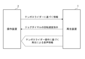
[出力部による出力処理]
出力部52は、上述したように、判定部51による判定結果に基づいて、検出部4による検出結果に基づく情報を再生装置1に出力する。以下では、プレイヤー部2Aのジョグダイヤル21Aを例に挙げて、再生装置1への出力処理について説明する。プレイヤー部2Bのジョグダイヤル21Bについても同様に、再生装置1への出力処理が行われる。
出力部52は、判定部51により判定した4つの状態(STATE 1~4)に基づいて、適切な情報を再生装置1に出力する。図4Aおよび図4Bは、出力部52による出力処理について説明する図である。 [Output processing by the output unit]
As described above, theoutput unit 52 outputs information based on the detection result of the detection unit 4 to the reproduction device 1 based on the determination result of the determination unit 51 . Below, the jog dial 21A of the player section 2A is taken as an example to explain the output processing to the playback device 1. FIG. Output processing to the playback device 1 is similarly performed for the jog dial 21B of the player section 2B.
Theoutput unit 52 outputs appropriate information to the playback device 1 based on the four states (STATE 1 to 4) determined by the determination unit 51 . 4A and 4B are diagrams illustrating output processing by the output unit 52. FIG.
出力部52は、上述したように、判定部51による判定結果に基づいて、検出部4による検出結果に基づく情報を再生装置1に出力する。以下では、プレイヤー部2Aのジョグダイヤル21Aを例に挙げて、再生装置1への出力処理について説明する。プレイヤー部2Bのジョグダイヤル21Bについても同様に、再生装置1への出力処理が行われる。
出力部52は、判定部51により判定した4つの状態(STATE 1~4)に基づいて、適切な情報を再生装置1に出力する。図4Aおよび図4Bは、出力部52による出力処理について説明する図である。 [Output processing by the output unit]
As described above, the
The
(1)接触なし:STATE 1
判定部51によりジョグダイヤル21Aへのユーザーの接触がないと判定された場合、出力部52は、プラッター部211Aの回転速度Sr1に基づく再生速度Sp1、および、天板部212Aの回転速度Sr2に基づく再生速度Sp2を出力せずに、テンポスライダー22Aにより設定された再生速度Sp0を出力する。これは、モータライズドジョグダイヤルであるジョグダイヤル21Aにおいて発生する回転速度のムラに起因し、プラッター部211Aの回転速度Sr1に基づく再生速度Sp1、および、天板部212Aの回転速度Sr2に基づく再生速度Sp2にもムラが反映されることを防ぐための処理である。 (1) No contact:STATE 1
When thedetermination unit 51 determines that the user does not touch the jog dial 21A, the output unit 52 performs playback based on the rotation speed Sr1 of the platter unit 211A and the rotation speed Sr2 of the top plate unit 212A. The playback speed Sp0 set by the tempo slider 22A is output without outputting the speed Sp2. This is due to unevenness in the rotational speed of the jog dial 21A, which is a motorized jog dial. This is a process for preventing unevenness from being reflected in the .
判定部51によりジョグダイヤル21Aへのユーザーの接触がないと判定された場合、出力部52は、プラッター部211Aの回転速度Sr1に基づく再生速度Sp1、および、天板部212Aの回転速度Sr2に基づく再生速度Sp2を出力せずに、テンポスライダー22Aにより設定された再生速度Sp0を出力する。これは、モータライズドジョグダイヤルであるジョグダイヤル21Aにおいて発生する回転速度のムラに起因し、プラッター部211Aの回転速度Sr1に基づく再生速度Sp1、および、天板部212Aの回転速度Sr2に基づく再生速度Sp2にもムラが反映されることを防ぐための処理である。 (1) No contact:
When the
一般に、モータライズドジョグダイヤルでは、プラッター部211Aの回転速度Sr1に基づく再生速度Sp1、および、天板部212Aの回転速度Sr2に基づく再生速度Sp2に基づいて再生処理を行っている。
これに対し、本実施形態においては、判定部51によりジョグダイヤル21Aへのユーザーの接触がないと判定された場合、図4Aに示すように、操作装置2の出力部52は、テンポスライダー22Aに基づく情報を出力する。そして、再生装置1は、テンポスライダー22Aに基づく情報にしたがって再生処理を行う。その結果、モータライズドジョグダイヤルであるジョグダイヤル21Aにおいて発生する回転速度のムラにより、再生される楽曲の音質が悪化し、オーディオ性能の項目である歪率にも影響を及ぼすことを防ぐことができる。
なお、出力部52により出力される情報は、「ジョグダイヤル21Aへのユーザーの接触がない」ことを示す情報を含んでもよい。 Generally, in the motorized jog dial, reproduction processing is performed based on a reproduction speed Sp1 based on the rotational speed Sr1 of theplatter portion 211A and a reproduction speed Sp2 based on the rotational speed Sr2 of the top plate portion 212A.
On the other hand, in the present embodiment, when thedetermination unit 51 determines that the user has not touched the jog dial 21A, the output unit 52 of the operation device 2 outputs the tempo slider 22A based on the tempo slider 22A, as shown in FIG. 4A. Output information. Then, the playback device 1 performs playback processing according to the information based on the tempo slider 22A. As a result, it is possible to prevent the deterioration of the sound quality of the reproduced music due to the uneven rotation speed generated in the jog dial 21A, which is a motorized jog dial, and the influence on the distortion factor, which is an item of audio performance.
The information output by theoutput unit 52 may include information indicating that "the jog dial 21A is not touched by the user".
これに対し、本実施形態においては、判定部51によりジョグダイヤル21Aへのユーザーの接触がないと判定された場合、図4Aに示すように、操作装置2の出力部52は、テンポスライダー22Aに基づく情報を出力する。そして、再生装置1は、テンポスライダー22Aに基づく情報にしたがって再生処理を行う。その結果、モータライズドジョグダイヤルであるジョグダイヤル21Aにおいて発生する回転速度のムラにより、再生される楽曲の音質が悪化し、オーディオ性能の項目である歪率にも影響を及ぼすことを防ぐことができる。
なお、出力部52により出力される情報は、「ジョグダイヤル21Aへのユーザーの接触がない」ことを示す情報を含んでもよい。 Generally, in the motorized jog dial, reproduction processing is performed based on a reproduction speed Sp1 based on the rotational speed Sr1 of the
On the other hand, in the present embodiment, when the
The information output by the
(2)接触あり(天板部212Aのみ):STATE 2
判定部51によりジョグダイヤル21Aへの天板部212Aへのユーザーの接触があると判定された場合、出力部52は、プラッター部211Aの回転速度Sr1に基づく再生速度Sp1、および、天板部212Aの回転速度Sr2に基づく再生速度Sp2を出力する。
つまり、判定部51によりジョグダイヤル21Aへの天板部212Aへのユーザーの接触があると判定された場合、図4Bに示すように、操作装置2の出力部52は、ジョグダイヤル21Aに基づく情報を出力する。そして、再生装置1は、ジョグダイヤル21Aに基づく情報にしたがって再生処理を行う。その結果、判定部51によりジョグダイヤル21Aへの天板部212Aへのユーザーの接触があると判定された場合、ジョグダイヤル21Aにおいて実際に検出された情報に基づいて、スクラッチ再生処理等を行うことができる。
なお、出力部52により出力される情報は、再生速度に限らず、回転速度、回転角、及び回転方向等を含んでもよい。また、「ジョグダイヤル21Aへの天板部212Aへのユーザーの接触がある」ことを示す情報を含んでもよい。 (2) With contact (top plate portion 212A only): STATE 2
When thedetermination unit 51 determines that the user touches the jog dial 21A to the top plate portion 212A, the output portion 52 sets the reproduction speed Sp1 based on the rotation speed Sr1 of the platter portion 211A and the rotation speed of the top plate portion 212A. A reproduction speed Sp2 based on the rotation speed Sr2 is output.
In other words, when thedetermination unit 51 determines that the top plate portion 212A of the jog dial 21A is touched by the user, the output unit 52 of the operation device 2 outputs information based on the jog dial 21A as shown in FIG. 4B. do. Then, the playback device 1 performs playback processing according to information based on the jog dial 21A. As a result, when the determination unit 51 determines that the top plate portion 212A of the jog dial 21A has been touched by the user, it is possible to perform scratch reproduction processing or the like based on the information actually detected by the jog dial 21A. .
The information output by theoutput unit 52 is not limited to the reproduction speed, and may include rotation speed, rotation angle, rotation direction, and the like. Further, it may include information indicating that "there is a user's contact with the top plate portion 212A of the jog dial 21A".
判定部51によりジョグダイヤル21Aへの天板部212Aへのユーザーの接触があると判定された場合、出力部52は、プラッター部211Aの回転速度Sr1に基づく再生速度Sp1、および、天板部212Aの回転速度Sr2に基づく再生速度Sp2を出力する。
つまり、判定部51によりジョグダイヤル21Aへの天板部212Aへのユーザーの接触があると判定された場合、図4Bに示すように、操作装置2の出力部52は、ジョグダイヤル21Aに基づく情報を出力する。そして、再生装置1は、ジョグダイヤル21Aに基づく情報にしたがって再生処理を行う。その結果、判定部51によりジョグダイヤル21Aへの天板部212Aへのユーザーの接触があると判定された場合、ジョグダイヤル21Aにおいて実際に検出された情報に基づいて、スクラッチ再生処理等を行うことができる。
なお、出力部52により出力される情報は、再生速度に限らず、回転速度、回転角、及び回転方向等を含んでもよい。また、「ジョグダイヤル21Aへの天板部212Aへのユーザーの接触がある」ことを示す情報を含んでもよい。 (2) With contact (
When the
In other words, when the
The information output by the
(3)接触あり(プラッター部211Aのみ):STATE 3
判定部51によりジョグダイヤル21Aへのプラッター部211Aへのユーザーの接触があると判定された場合、出力部52は、少なくともプラッター部211Aの回転速度Sr1に基づく再生速度Sp1を出力する。
つまり、判定部51によりジョグダイヤル21Aへのプラッター部211Aへのユーザーの接触があると判定された場合、上述した(2)と同様に、図4Bに示すように、操作装置2の出力部52は、ジョグダイヤル21Aに基づく情報を出力する。そして、再生装置1は、ジョグダイヤル21Aに基づく情報にしたがって再生処理を行う。その結果、判定部51によりジョグダイヤル21Aへのプラッター部211Aへのユーザーの接触があると判定された場合、ジョグダイヤル21Aにおいて実際に検出された情報に基づいて、ピッチベンド再生処理等を行うことができる。
なお、判定部51によりジョグダイヤル21Aへのプラッター部211Aへのユーザーの接触があると判定された場合、出力部52は、プラッター部211Aの回転速度Sr1に基づく再生速度Sp1に加えて、天板部212Aの回転速度Sr2に基づく再生速度Sp2を出力してもよい。また、出力部52により出力される情報は、再生速度に限らず、回転速度、回転角、及び回転方向等を含んでもよい。また、「ジョグダイヤル21Aへの天板部212Aへのユーザーの接触がある」ことを示す情報を含んでもよい。 (3) With contact (platter portion 211A only): STATE 3
When thedetermination unit 51 determines that the user touches the jog dial 21A and the platter unit 211A, the output unit 52 outputs the reproduction speed Sp1 based on at least the rotation speed Sr1 of the platter unit 211A.
That is, when thedetermination unit 51 determines that the user touches the jog dial 21A and the platter unit 211A, the output unit 52 of the operation device 2 outputs the , to output information based on the jog dial 21A. Then, the playback device 1 performs playback processing according to information based on the jog dial 21A. As a result, when the determination unit 51 determines that the platter unit 211A of the jog dial 21A has been touched by the user, pitch bend reproduction processing and the like can be performed based on the information actually detected by the jog dial 21A.
When thedetermination unit 51 determines that the jog dial 21A has touched the platter unit 211A by the user, the output unit 52 sets the reproduction speed Sp1 based on the rotation speed Sr1 of the platter unit 211A and the top plate unit A reproduction speed Sp2 based on the rotational speed Sr2 of 212A may be output. Information output by the output unit 52 is not limited to the reproduction speed, and may include rotation speed, rotation angle, rotation direction, and the like. Further, it may include information indicating that "there is a user's contact with the top plate portion 212A of the jog dial 21A".
判定部51によりジョグダイヤル21Aへのプラッター部211Aへのユーザーの接触があると判定された場合、出力部52は、少なくともプラッター部211Aの回転速度Sr1に基づく再生速度Sp1を出力する。
つまり、判定部51によりジョグダイヤル21Aへのプラッター部211Aへのユーザーの接触があると判定された場合、上述した(2)と同様に、図4Bに示すように、操作装置2の出力部52は、ジョグダイヤル21Aに基づく情報を出力する。そして、再生装置1は、ジョグダイヤル21Aに基づく情報にしたがって再生処理を行う。その結果、判定部51によりジョグダイヤル21Aへのプラッター部211Aへのユーザーの接触があると判定された場合、ジョグダイヤル21Aにおいて実際に検出された情報に基づいて、ピッチベンド再生処理等を行うことができる。
なお、判定部51によりジョグダイヤル21Aへのプラッター部211Aへのユーザーの接触があると判定された場合、出力部52は、プラッター部211Aの回転速度Sr1に基づく再生速度Sp1に加えて、天板部212Aの回転速度Sr2に基づく再生速度Sp2を出力してもよい。また、出力部52により出力される情報は、再生速度に限らず、回転速度、回転角、及び回転方向等を含んでもよい。また、「ジョグダイヤル21Aへの天板部212Aへのユーザーの接触がある」ことを示す情報を含んでもよい。 (3) With contact (
When the
That is, when the
When the
(4)その他の理由による状態遷移:STATE 4
判定部51により(1)から(3)以外の理由による状態遷移があると判定された場合、出力部52は、対応する情報を出力する。例えば、プレイ/ポーズボタン24Aにより楽曲の再生開始、または停止操作が行われた場合、出力部52は、当該操作を示す情報を出力する。 (4) State transition due to other reasons:STATE 4
When thedetermination unit 51 determines that there is a state transition for a reason other than (1) to (3), the output unit 52 outputs corresponding information. For example, when the play/pause button 24A is used to start or stop playing music, the output unit 52 outputs information indicating the operation.
判定部51により(1)から(3)以外の理由による状態遷移があると判定された場合、出力部52は、対応する情報を出力する。例えば、プレイ/ポーズボタン24Aにより楽曲の再生開始、または停止操作が行われた場合、出力部52は、当該操作を示す情報を出力する。 (4) State transition due to other reasons:
When the
[判定処理に基づく情報の出力処理]
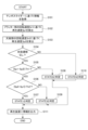
図5は、制御部5により実行される処理を示すフローチャートである。以下では、プレイヤー部2Aのジョグダイヤル21Aを例に挙げて説明する。プレイヤー部2Bのジョグダイヤル21Bについても、同様の処理が行われる。 [Information Output Processing Based on Judgment Processing]
FIG. 5 is a flow chart showing the processing executed by thecontrol unit 5. As shown in FIG. The jog dial 21A of the player section 2A will be described below as an example. Similar processing is performed for the jog dial 21B of the player section 2B.
図5は、制御部5により実行される処理を示すフローチャートである。以下では、プレイヤー部2Aのジョグダイヤル21Aを例に挙げて説明する。プレイヤー部2Bのジョグダイヤル21Bについても、同様の処理が行われる。 [Information Output Processing Based on Judgment Processing]
FIG. 5 is a flow chart showing the processing executed by the
判定部51が、検出部4からテンポスライダー22Aに基づく情報を取得する(ステップS101)。
次に、判定部51が、検出部4の第1検出部41Aから、プラッター部211Aの回転速度Sr1を示す情報を取得し、回転速度Sr1に基づく再生速度Sp1を算出する(ステップS102)。また、判定部51が、検出部4の第2検出部42Aから、天板部212Aの回転速度Sr2を示す情報を取得し、回転速度Sr2に基づく再生速度Sp2を算出する(ステップS103)。
この後、判定部51は、ジョグダイヤル21Aおよびテンポスライダー22Aへの操作とは異なる別の状態遷移があるか否かを判定する(ステップS104)。
ステップS104の判定処理にて、状態遷移があると判定すると(ステップS104:NO)、制御部5は、後述するステップS110に進む。 Thedetermination unit 51 acquires information based on the tempo slider 22A from the detection unit 4 (step S101).
Next, thedetermination unit 51 acquires information indicating the rotation speed Sr1 of the platter unit 211A from the first detection unit 41A of the detection unit 4, and calculates the reproduction speed Sp1 based on the rotation speed Sr1 (step S102). Further, the determination unit 51 acquires information indicating the rotation speed Sr2 of the top plate unit 212A from the second detection unit 42A of the detection unit 4, and calculates the reproduction speed Sp2 based on the rotation speed Sr2 (step S103).
After that, thedetermination unit 51 determines whether or not there is another state transition different from the operation of the jog dial 21A and the tempo slider 22A (step S104).
When it is determined in the determination process of step S104 that there is a state transition (step S104: NO), thecontrol unit 5 proceeds to step S110, which will be described later.
次に、判定部51が、検出部4の第1検出部41Aから、プラッター部211Aの回転速度Sr1を示す情報を取得し、回転速度Sr1に基づく再生速度Sp1を算出する(ステップS102)。また、判定部51が、検出部4の第2検出部42Aから、天板部212Aの回転速度Sr2を示す情報を取得し、回転速度Sr2に基づく再生速度Sp2を算出する(ステップS103)。
この後、判定部51は、ジョグダイヤル21Aおよびテンポスライダー22Aへの操作とは異なる別の状態遷移があるか否かを判定する(ステップS104)。
ステップS104の判定処理にて、状態遷移があると判定すると(ステップS104:NO)、制御部5は、後述するステップS110に進む。 The
Next, the
After that, the
When it is determined in the determination process of step S104 that there is a state transition (step S104: NO), the
ステップS104の判定処理にて、状態遷移がないと判定部51が判定すると(ステップS104:YES)、判定部51が、プラッター部211Aの回転速度Sr1に基づく再生速度Sp1と、天板部212Aの回転速度Sr2に基づく再生速度Sp2との差分が所定の閾値Th1未満であるか否かを判定する(ステップS105)。
ステップS105の判定処理にて、差分が所定の閾値Th1以上であると判定すると(ステップS105:NO)、制御部5は、後述するステップS108に進む。 In the determination process of step S104, when thedetermination unit 51 determines that there is no state transition (step S104: YES), the determination unit 51 determines the reproduction speed Sp1 based on the rotation speed Sr1 of the platter unit 211A and the It is determined whether or not the difference between the rotation speed Sr2 and the reproduction speed Sp2 is less than a predetermined threshold Th1 (step S105).
When it is determined in the determination process of step S105 that the difference is equal to or greater than the predetermined threshold value Th1 (step S105: NO), thecontroller 5 proceeds to step S108, which will be described later.
ステップS105の判定処理にて、差分が所定の閾値Th1以上であると判定すると(ステップS105:NO)、制御部5は、後述するステップS108に進む。 In the determination process of step S104, when the
When it is determined in the determination process of step S105 that the difference is equal to or greater than the predetermined threshold value Th1 (step S105: NO), the
ステップS105の判定処理にて、差分が所定の閾値Th1未満であると判定されると(ステップS105:YES)、判定部51が、テンポスライダー22Aにより設定された再生速度Sp0と、プラッター部211Aの回転速度Sr1に基づく再生速度Sp1との差分が所定の閾値Th2未満であるか否かを判定する(ステップS106)。
ステップS106の判定処理にて、テンポスライダー22Aにより設定された再生速度Sp0と、プラッター部211Aの回転速度Sr1に基づく再生速度Sp1との差分が所定の閾値Th2以上であると判定すると(ステップS106:NO)、制御部5は、後述するステップS109に進む。 When it is determined in the determination processing in step S105 that the difference is less than the predetermined threshold value Th1 (step S105: YES), thedetermination unit 51 sets the reproduction speed Sp0 set by the tempo slider 22A and the speed of the platter unit 211A. It is determined whether or not the difference between the rotation speed Sr1 and the reproduction speed Sp1 is less than a predetermined threshold Th2 (step S106).
In the determination process of step S106, if it is determined that the difference between the reproduction speed Sp0 set by thetempo slider 22A and the reproduction speed Sp1 based on the rotation speed Sr1 of the platter section 211A is equal to or greater than the predetermined threshold Th2 (step S106: NO), the controller 5 proceeds to step S109, which will be described later.
ステップS106の判定処理にて、テンポスライダー22Aにより設定された再生速度Sp0と、プラッター部211Aの回転速度Sr1に基づく再生速度Sp1との差分が所定の閾値Th2以上であると判定すると(ステップS106:NO)、制御部5は、後述するステップS109に進む。 When it is determined in the determination processing in step S105 that the difference is less than the predetermined threshold value Th1 (step S105: YES), the
In the determination process of step S106, if it is determined that the difference between the reproduction speed Sp0 set by the
ステップS106の判定処理にて、テンポスライダー22Aにより設定された再生速度Sp0と、プラッター部211Aの回転速度Sr1に基づく再生速度Sp1との差分が所定の閾値Th2未満であると判定されると(ステップS106:YES)、テンポスライダー22Aにより設定された再生速度Sp0と、プラッター部211Aの回転速度Sr1に基づく再生速度Sp1と、天板部212Aの回転速度Sr2に基づく再生速度Sp2とが略等しくなるため、判定部51は、ジョグダイヤル21Aへのユーザーの接触の有無の状態はSTATE 1であると判定する(ステップS107)。
In the determination processing of step S106, if it is determined that the difference between the reproduction speed Sp0 set by the tempo slider 22A and the reproduction speed Sp1 based on the rotation speed Sr1 of the platter unit 211A is less than the predetermined threshold Th2 (step S106: YES), because the reproduction speed Sp0 set by the tempo slider 22A, the reproduction speed Sp1 based on the rotation speed Sr1 of the platter section 211A, and the reproduction speed Sp2 based on the rotation speed Sr2 of the top plate section 212A are substantially equal. , the determination unit 51 determines that the state of the user's contact with the jog dial 21A is STATE 1 (step S107).
ステップS105の判定処理にて、差分が所定の閾値Th1以上であると判定すると(ステップS105:NO)、プラッター部211Aの回転速度Sr1に基づく再生速度Sp1と、天板部212Aの回転速度Sr2に基づく再生速度Sp2とが異なるため、判定部51は、ジョグダイヤル21Aへのユーザーの接触の有無の状態はSTATE 2であると判定する(ステップS108)。
また、ステップS106の判定処理にて、テンポスライダー22Aにより設定された再生速度Sp0と、プラッター部211Aの回転速度Sr1に基づく再生速度Sp1との差分が所定の閾値Th2以上であると判定すると(ステップS106:NO)、テンポスライダー22Aにより設定された再生速度Sp0と、プラッター部211Aの回転速度Sr1に基づく再生速度Sp1とが異なり、かつ、プラッター部211Aの回転速度Sr1に基づく再生速度Sp1と、天板部212Aの回転速度Sr2に基づく再生速度Sp2とが略等しくなるため、判定部51は、ジョグダイヤル21Aへのユーザーの接触の有無の状態はSTATE 3であると判定する(ステップS109)。
さらに、ステップS104の判定処理にて、状態遷移があると判定すると(ステップS104:NO)、制御部5は、ジョグダイヤル21Aへのユーザーの接触の有無の状態はSTATE 4であると判定する(ステップS110)。 In the determination process of step S105, when it is determined that the difference is equal to or greater than the predetermined threshold Th1 (step S105: NO), the reproduction speed Sp1 based on the rotation speed Sr1 of theplatter portion 211A and the rotation speed Sr2 of the top plate portion 212A Since the reproduction speed Sp2 is different from the base reproduction speed Sp2, the determination unit 51 determines that the state of whether or not the user touches the jog dial 21A is STATE 2 (step S108).
Further, in the determination processing of step S106, if it is determined that the difference between the reproduction speed Sp0 set by thetempo slider 22A and the reproduction speed Sp1 based on the rotation speed Sr1 of the platter section 211A is equal to or greater than a predetermined threshold Th2 (step S106: NO), the reproduction speed Sp0 set by the tempo slider 22A is different from the reproduction speed Sp1 based on the rotational speed Sr1 of the platter section 211A, and the reproduction speed Sp1 based on the rotational speed Sr1 of the platter section 211A and the Since the reproduction speed Sp2 based on the rotation speed Sr2 of the plate portion 212A is substantially equal, the determination portion 51 determines that the state of the user's contact with the jog dial 21A is STATE 3 (step S109).
Further, when it is determined that there is a state transition in the determination process of step S104 (step S104: NO), thecontrol unit 5 determines that the state of whether or not the user touches the jog dial 21A is STATE 4 (step S104: NO). S110).
また、ステップS106の判定処理にて、テンポスライダー22Aにより設定された再生速度Sp0と、プラッター部211Aの回転速度Sr1に基づく再生速度Sp1との差分が所定の閾値Th2以上であると判定すると(ステップS106:NO)、テンポスライダー22Aにより設定された再生速度Sp0と、プラッター部211Aの回転速度Sr1に基づく再生速度Sp1とが異なり、かつ、プラッター部211Aの回転速度Sr1に基づく再生速度Sp1と、天板部212Aの回転速度Sr2に基づく再生速度Sp2とが略等しくなるため、判定部51は、ジョグダイヤル21Aへのユーザーの接触の有無の状態はSTATE 3であると判定する(ステップS109)。
さらに、ステップS104の判定処理にて、状態遷移があると判定すると(ステップS104:NO)、制御部5は、ジョグダイヤル21Aへのユーザーの接触の有無の状態はSTATE 4であると判定する(ステップS110)。 In the determination process of step S105, when it is determined that the difference is equal to or greater than the predetermined threshold Th1 (step S105: NO), the reproduction speed Sp1 based on the rotation speed Sr1 of the
Further, in the determination processing of step S106, if it is determined that the difference between the reproduction speed Sp0 set by the
Further, when it is determined that there is a state transition in the determination process of step S104 (step S104: NO), the
出力部52は、ステップS107からS110のいずれかで判定されたジョグダイヤル21Aへのユーザーの接触の有無の状態に基づいて、再生装置1に情報を出力する(ステップS111)。
一連の処理は、例えば操作装置2の電源がオフされる等、所定の終了操作が行われるまで、繰り返し実行される。 Theoutput unit 52 outputs information to the playback device 1 based on whether or not the user touches the jog dial 21A determined in any one of steps S107 to S110 (step S111).
A series of processes are repeatedly executed until a predetermined end operation such as turning off the power of theoperation device 2 is performed.
一連の処理は、例えば操作装置2の電源がオフされる等、所定の終了操作が行われるまで、繰り返し実行される。 The
A series of processes are repeatedly executed until a predetermined end operation such as turning off the power of the
[実施形態の効果]
以上説明した本実施形態に係る操作装置2によれば、以下の効果を奏することができる。
回転操作子であるジョグダイヤル21A、21Bと、ジョグダイヤル21A、21Bへのユーザーの接触の有無を判定する判定部51と、判定部51により接触がないと判定されるとジョグダイヤル21A、21Bに予め設定された再生速度を示す第1情報を出力し、判定部51により接触があると判定されると、第1情報とは異なる第2情報を出力する出力部52とを備える。
このような構成により、モータライズドジョグダイヤルであるジョグダイヤル21A、21Bにおいて回転速度にムラが発生する場合であっても、好適な楽曲の再生を行うための情報を出力することができる。そのため、音質が悪化し、オーディオ性能の項目である歪率にも影響を及ぼすという問題を防ぐことができるとともに、DJプレイにおけるミックス処理の対象となる複数の楽曲間で正確に再生位置を合わせることが困難になり、DJ演奏の質も低下するという問題も防ぐことができる。 [Effects of Embodiment]
According to theoperating device 2 according to the present embodiment described above, the following effects can be obtained.
The jog dials 21A and 21B, which are rotary operators, adetermination unit 51 that determines whether or not the user touches the jog dials 21A and 21B, and if the determination unit 51 determines that there is no contact, the jog dials 21A and 21B are set in advance. and an output unit 52 for outputting first information indicating the playback speed, and for outputting second information different from the first information when the determination unit 51 determines that there is contact.
With such a configuration, even if the rotational speed of the jog dials 21A and 21B, which are motorized jog dials, is uneven, it is possible to output information for reproducing suitable music. Therefore, it is possible to prevent the problem that the sound quality deteriorates and the distortion rate, which is an item of audio performance, is affected, and at the same time, it is possible to accurately match the playback position between multiple songs to be mixed in DJ play. It is possible to prevent the problem that the DJ performance becomes difficult and the quality of the DJ performance deteriorates.
以上説明した本実施形態に係る操作装置2によれば、以下の効果を奏することができる。
回転操作子であるジョグダイヤル21A、21Bと、ジョグダイヤル21A、21Bへのユーザーの接触の有無を判定する判定部51と、判定部51により接触がないと判定されるとジョグダイヤル21A、21Bに予め設定された再生速度を示す第1情報を出力し、判定部51により接触があると判定されると、第1情報とは異なる第2情報を出力する出力部52とを備える。
このような構成により、モータライズドジョグダイヤルであるジョグダイヤル21A、21Bにおいて回転速度にムラが発生する場合であっても、好適な楽曲の再生を行うための情報を出力することができる。そのため、音質が悪化し、オーディオ性能の項目である歪率にも影響を及ぼすという問題を防ぐことができるとともに、DJプレイにおけるミックス処理の対象となる複数の楽曲間で正確に再生位置を合わせることが困難になり、DJ演奏の質も低下するという問題も防ぐことができる。 [Effects of Embodiment]
According to the
The jog dials 21A and 21B, which are rotary operators, a
With such a configuration, even if the rotational speed of the jog dials 21A and 21B, which are motorized jog dials, is uneven, it is possible to output information for reproducing suitable music. Therefore, it is possible to prevent the problem that the sound quality deteriorates and the distortion rate, which is an item of audio performance, is affected, and at the same time, it is possible to accurately match the playback position between multiple songs to be mixed in DJ play. It is possible to prevent the problem that the DJ performance becomes difficult and the quality of the DJ performance deteriorates.
また、本実施形態に係る操作装置2によれば、ジョグダイヤル21A、21Bの回転速度を検出する検出部4をさらに備え、判定部51は、ジョグダイヤル21A、21Bに予め設定された再生速度と、検出部4により検出した回転速度に基づく再生速度との差分が所定の閾値未満である場合には、接触がないと判定する。そして、判定部51は、差分が所定の閾値以上である場合には接触があると判定し、出力部52は、判定部51により接触があると判定されると、第2情報として、検出部4により検出した回転速度に基づく再生速度を示す情報を出力する。そのため、接触の有無を検出する特有のセンサを備えることなく、ジョグダイヤル21A、21Bへのユーザーの接触の有無を判定することができる。また、ジョグダイヤル21A、21Bへのユーザーの接触の有無に応じて、好適な楽曲の再生を行うための情報を出力することができる。
Further, according to the operating device 2 according to the present embodiment, the detection section 4 that detects the rotation speed of the jog dials 21A and 21B is further provided. When the difference between the rotation speed detected by the unit 4 and the reproduction speed based on the rotation speed is less than a predetermined threshold value, it is determined that there is no contact. Then, when the difference is equal to or greater than a predetermined threshold value, the determination unit 51 determines that there is contact, and when the determination unit 51 determines that there is contact, the output unit 52 outputs the detection unit 4 outputs information indicating the reproduction speed based on the rotation speed detected by 4. Therefore, it is possible to determine whether or not the user touches the jog dials 21A and 21B without providing a special sensor for detecting the presence or absence of contact. Further, it is possible to output information for reproducing suitable music depending on whether or not the user touches the jog dials 21A and 21B.
また、本実施形態に係る操作装置2によれば、ジョグダイヤル21A、21Bは、モーターにより回転駆動される第1操作部材であるプラッター部211A、211Bと、プラッター部211A、211Bと同軸でプラッター部211A、211Bに対して相対的に回転可能な第2操作部材である天板部212A、212Bとを含む。検出部4は、プラッター部211A、211Bの回転速度を検出する第1検出部41A、41Bと、天板部212A、212Bの回転速度を検出する第2検出部42A、42Bとを含む。そして、判定部51は、第1検出部41A、41Bにより検出したプラッター部211A、211Bおよび天板部212A、212Bの回転速度(Sr1、Sr2)に基づく再生速度(Sp1、Sp2)のそれぞれと、ジョグダイヤル21A、21Bに予め設定された再生速度Sp0との差分がいずれも所定の閾値未満である場合には、接触がないと判定する。また、判定部51は、ジョグダイヤル21A、21Bに予め設定された再生速度Sp0と、プラッター部211A、211Bの回転速度Sr1に基づく再生速度Sp1、および、天板部212A、212Bの回転速度Sr2に基づく再生速度Sp2のそれぞれとの差分がいずれも所定の閾値以上である場合には、接触があると判定する。また、判定部51は、プラッター部211A、211Bの回転速度Sr1に基づく再生速度Sp1と、天板部212A、212Bの回転速度Sr2に基づく再生速度Sp2との差分に基づいて、プラッター部211A、211Bおよび天板部212A、212Bのそれぞれにおける接触の有無を判定する。
そのため、プラッター部211A、211Bおよび天板部212A、212Bのそれぞれにおける接触の有無を個別に判定することができる。また、プラッター部211A、211Bおよび天板部212A、212Bのそれぞれにおける接触の有無に応じて、好適な楽曲の再生を行うための情報を出力することができる。 Further, according to theoperating device 2 according to the present embodiment, the jog dials 21A and 21B include the platter portions 211A and 211B, which are the first operation members that are rotationally driven by the motor, and the platter portions 211A and 211B and are coaxial with the platter portion 211A. , and 211B, which are second operation members that are rotatable relative to each other. The detector 4 includes first detectors 41A and 41B that detect the rotational speeds of the platter portions 211A and 211B, and second detectors 42A and 42B that detect the rotational speeds of the top plate portions 212A and 212B. Then, the determination unit 51 determines the reproduction speeds (Sp1, Sp2) based on the rotation speeds (Sr1, Sr2) of the platter units 211A, 211B and the top plate units 212A, 212B detected by the first detection units 41A, 41B, and If the difference from the playback speed Sp0 preset in the jog dials 21A and 21B is less than a predetermined threshold value, it is determined that there is no contact. Further, the determination unit 51 determines the reproduction speed Sp0 preset in the jog dials 21A and 21B, the reproduction speed Sp1 based on the rotation speed Sr1 of the platter units 211A and 211B, and the rotation speed Sr2 of the top plate units 212A and 212B. If the difference from each reproduction speed Sp2 is equal to or greater than a predetermined threshold value, it is determined that there is contact. Further, the determination unit 51 determines the platter units 211A and 211B based on the difference between the reproduction speed Sp1 based on the rotation speed Sr1 of the platter units 211A and 211B and the reproduction speed Sp2 based on the rotation speed Sr2 of the top plate units 212A and 212B. and the presence or absence of contact in each of the top plate portions 212A and 212B.
Therefore, it is possible to individually determine whether the platter portions 211A and 211B and the top plate portions 212A and 212B are in contact with each other. Further, it is possible to output information for suitable music reproduction depending on whether or not the platter portions 211A and 211B and the top plate portions 212A and 212B are touched.
そのため、プラッター部211A、211Bおよび天板部212A、212Bのそれぞれにおける接触の有無を個別に判定することができる。また、プラッター部211A、211Bおよび天板部212A、212Bのそれぞれにおける接触の有無に応じて、好適な楽曲の再生を行うための情報を出力することができる。 Further, according to the
Therefore, it is possible to individually determine whether the
また、本実施形態に係る音響装置100によれば、上述した操作装置2と、楽曲データを再生する再生装置1とを備え、出力部52は、再生装置1に第1情報と第2情報との少なくとも一方を出力する。そのため、再生装置1は、操作装置2から出力された情報に基づいて、楽曲の好適な再生を実現することができる。
Further, according to the audio device 100 according to the present embodiment, the operating device 2 described above and the reproducing device 1 that reproduces music data are provided. output at least one of Therefore, the reproduction device 1 can realize suitable reproduction of music based on the information output from the operation device 2 .
[実施形態の変形]
本発明は、上記実施形態に限定されるものではなく、本発明の目的を達成できる範囲での変形、改良等は本発明に含まれるものである。
上記実施形態では、検出部4は、ジョグダイヤル21A、21Bにおける回転速度を検出し、判定部51は、検出部4による検出結果に基づいて、ジョグダイヤル21A、21Bへのユーザーの接触の有無を判定する例を示したが、本発明はこの例に限定されない。
検出部4は、例えば、ジョグダイヤル21A、21Bへのユーザーの接触の有無を検出するタッチセンサを含み、タッチセンサの出力に基づいて、ジョグダイヤル21A、21Bへのユーザーの接触の有無を判定する構成としてもよい。なお、タッチセンサは、ジョグダイヤル21A、21Bを構成するプラッター部211A、211Bおよび天板部212A、212Bのそれぞれに設けられ、回転速度を個別に検出する構成であってもよい。
また、タッチセンサは、押圧を検出するものであってもよいし、静電容量式等、ユーザーの操作を検出できるものであればよく、センシングの方式は問わない。また、本実施形態で説明したジョグダイヤル21A、21Bにおける回転速度の検出結果と、タッチセンサによる検出結果とを組み合わせてジョグダイヤル21A、21Bへのユーザーの接触の有無の判定を行う構成としてもよい。 [Modification of Embodiment]
The present invention is not limited to the above-described embodiments, and includes modifications, improvements, and the like within the scope of achieving the object of the present invention.
In the above embodiment, thedetection unit 4 detects the rotational speed of the jog dials 21A and 21B, and the determination unit 51 determines whether the jog dials 21A and 21B are touched by the user based on the detection result of the detection unit 4. Although an example has been given, the invention is not limited to this example.
Thedetection unit 4 includes, for example, touch sensors that detect whether or not the jog dials 21A and 21B are touched by the user, and determines whether or not the jog dials 21A and 21B are touched by the user based on the output of the touch sensors. good too. The touch sensors may be provided in the platter portions 211A and 211B and the top plate portions 212A and 212B that constitute the jog dials 21A and 21B, respectively, and may be configured to individually detect the rotation speed.
Further, the touch sensor may be one that detects pressure, or one that can detect a user's operation, such as a capacitive sensor, and the sensing method is not limited. Further, the detection result of the rotation speed of the jog dials 21A and 21B described in this embodiment and the detection result of the touch sensor may be combined to determine whether or not the jog dials 21A and 21B are touched by the user.
本発明は、上記実施形態に限定されるものではなく、本発明の目的を達成できる範囲での変形、改良等は本発明に含まれるものである。
上記実施形態では、検出部4は、ジョグダイヤル21A、21Bにおける回転速度を検出し、判定部51は、検出部4による検出結果に基づいて、ジョグダイヤル21A、21Bへのユーザーの接触の有無を判定する例を示したが、本発明はこの例に限定されない。
検出部4は、例えば、ジョグダイヤル21A、21Bへのユーザーの接触の有無を検出するタッチセンサを含み、タッチセンサの出力に基づいて、ジョグダイヤル21A、21Bへのユーザーの接触の有無を判定する構成としてもよい。なお、タッチセンサは、ジョグダイヤル21A、21Bを構成するプラッター部211A、211Bおよび天板部212A、212Bのそれぞれに設けられ、回転速度を個別に検出する構成であってもよい。
また、タッチセンサは、押圧を検出するものであってもよいし、静電容量式等、ユーザーの操作を検出できるものであればよく、センシングの方式は問わない。また、本実施形態で説明したジョグダイヤル21A、21Bにおける回転速度の検出結果と、タッチセンサによる検出結果とを組み合わせてジョグダイヤル21A、21Bへのユーザーの接触の有無の判定を行う構成としてもよい。 [Modification of Embodiment]
The present invention is not limited to the above-described embodiments, and includes modifications, improvements, and the like within the scope of achieving the object of the present invention.
In the above embodiment, the
The
Further, the touch sensor may be one that detects pressure, or one that can detect a user's operation, such as a capacitive sensor, and the sensing method is not limited. Further, the detection result of the rotation speed of the jog dials 21A and 21B described in this embodiment and the detection result of the touch sensor may be combined to determine whether or not the jog dials 21A and 21B are touched by the user.
上記実施形態では、ジョグダイヤル21A、21Bは、プラッター部211A、211Bおよび天板部212A、212Bを含み、天板部212A、212Bは、プラッター部211A、211Bに対して相対的に回転可能である例を示したが、本発明はこの例に限定されない。
ジョグダイヤル21A、21Bは、プラッター部211A、211Bおよび天板部212A、212Bに相当する部材が一体となって回転される構成であってもよい。このような場合、検出部4は、ジョグダイヤル21A、21B全体の回転速度を検出し、判定部51は、ジョグダイヤル21A、21Bに予め設定された再生速度と、検出部4により検出したジョグダイヤル21A、21B全体の回転速度に基づく再生速度との差分が所定の閾値未満である場合には、ジョグダイヤル21A、21Bへのユーザーの接触がないと判定し、差分が所定の閾値以上である場合には、ジョグダイヤル21A、21Bへのユーザーの接触があると判定すればよい。 In the above embodiment, the jog dials 21A, 21B include platter portions 211A, 211B and top plate portions 212A, 212B, and the top plate portions 212A, 212B are rotatable relative to the platter portions 211A, 211B. , the invention is not limited to this example.
The jog dials 21A and 21B may be configured such that members corresponding to the platter portions 211A and 211B and the top plate portions 212A and 212B are rotated together. In such a case, the detection unit 4 detects the rotation speed of the entire jog dials 21A and 21B, and the determination unit 51 detects the playback speed preset in the jog dials 21A and 21B and the jog dials 21A and 21B detected by the detection unit 4. When the difference from the playback speed based on the overall rotation speed is less than a predetermined threshold, it is determined that the user has not touched the jog dials 21A and 21B. It may be determined that the user has touched 21A and 21B.
ジョグダイヤル21A、21Bは、プラッター部211A、211Bおよび天板部212A、212Bに相当する部材が一体となって回転される構成であってもよい。このような場合、検出部4は、ジョグダイヤル21A、21B全体の回転速度を検出し、判定部51は、ジョグダイヤル21A、21Bに予め設定された再生速度と、検出部4により検出したジョグダイヤル21A、21B全体の回転速度に基づく再生速度との差分が所定の閾値未満である場合には、ジョグダイヤル21A、21Bへのユーザーの接触がないと判定し、差分が所定の閾値以上である場合には、ジョグダイヤル21A、21Bへのユーザーの接触があると判定すればよい。 In the above embodiment, the jog dials 21A, 21B include
The jog dials 21A and 21B may be configured such that members corresponding to the
また、本発明の操作装置は、楽曲データを再生する再生装置1に情報を出力するものに限らず、他の装置及び機器に情報を出力するものとして構成してもよい。
また、例えば、楽曲を再生する複数のプレイヤーと、プレイヤーを制御するミキサーとが一体化したDJシステム等にも、本発明を適用可能である。
また、上記の各実施形態では2つのプレイヤー部2Aおよび2Bを有する2チャンネルの操作装置が説明されたが、例えば4チャンネルの操作装置でも同様の機能が実現可能である。 Further, the operating device of the present invention is not limited to outputting information to the reproducingdevice 1 that reproduces music data, and may be configured to output information to other devices and devices.
Further, for example, the present invention can be applied to a DJ system or the like in which a plurality of players for reproducing music and a mixer for controlling the players are integrated.
Also, although the two-channel operating device having the two player sections 2A and 2B has been described in each of the above-described embodiments, the same functions can be realized with, for example, a four-channel operating device.
また、例えば、楽曲を再生する複数のプレイヤーと、プレイヤーを制御するミキサーとが一体化したDJシステム等にも、本発明を適用可能である。
また、上記の各実施形態では2つのプレイヤー部2Aおよび2Bを有する2チャンネルの操作装置が説明されたが、例えば4チャンネルの操作装置でも同様の機能が実現可能である。 Further, the operating device of the present invention is not limited to outputting information to the reproducing
Further, for example, the present invention can be applied to a DJ system or the like in which a plurality of players for reproducing music and a mixer for controlling the players are integrated.
Also, although the two-channel operating device having the two
1…再生装置、2…操作装置、2A,2B…プレイヤー、3…ミキサー、4…検出部、5…制御部、20A,20B,30…操作部、21A,21B…ジョグダイヤル、22A,22B…テンポスライダー、23A,23B…キューボタン、24A,24B…プレイ/ポーズボタン、25A,25B…パフォーマンスパッド、26A,26B…リセットボタン、27A,27B…時間設定ボタン、31A,31B…エフェクト選択つまみ、32A,32B…エフェクト量調整つまみ、33A,33B…チャンネルフェーダー、34…クロスフェーダー、41A,41B…第1検出部、42A,42B…第2検出部、51…判定部、52…出力部、211A,211B…プラッター部、212A,212B…天板部。
1playback device 2 operation device 2A, 2B player 3 mixer 4 detection unit 5 control unit 20A, 20B, 30 operation unit 21A, 21B jog dial 22A, 22B tempo Slider 23A, 23B... Cue button 24A, 24B... Play/ pause button 25A, 25B... Performance pad 26A, 26B... Reset button 27A, 27B... Time setting button 31A, 31B... Effect selection knob 32A, 32B... Effect amount adjustment knob, 33A, 33B... Channel fader, 34... Cross fader, 41A, 41B... First detector, 42A, 42B... Second detector, 51... Judgment part, 52... Output part, 211A, 211B ... platter section, 212A, 212B ... top plate section.
1
Claims (7)
- 回転操作子と、
前記回転操作子へのユーザーの接触の有無を判定する判定部と、
前記判定部により前記接触がないと判定されると、前記回転操作子に予め設定された再生速度を示す第1情報を出力し、前記判定部により前記接触があると判定されると、前記第1情報とは異なる第2情報を出力する出力部と、を備えることを特徴とする操作装置。 a rotary operator;
a determination unit that determines whether or not a user touches the rotary operator;
When the determining unit determines that there is no contact, first information indicating a reproduction speed set in advance to the rotary operator is output.When the determining unit determines that there is contact, the first information is output. and an output unit that outputs second information different from the first information. - 請求項1に記載の操作装置において、
前記回転操作子の回転速度を検出する検出部をさらに備え、
前記判定部は、前記回転操作子に予め設定された再生速度と、前記検出部により検出した前記回転速度に基づく再生速度との差分が所定の閾値未満である場合には、前記接触がないと判定する、ことを特徴とする操作装置。 The operating device according to claim 1,
further comprising a detection unit that detects the rotation speed of the rotary operator,
The determination unit determines that there is no contact when a difference between a reproduction speed preset for the rotary operator and a reproduction speed based on the rotation speed detected by the detection unit is less than a predetermined threshold. An operation device characterized by: - 請求項2に記載の操作装置において、
前記判定部は、前記差分が所定の閾値以上である場合には、前記接触があると判定し、
前記出力部は、前記判定部により前記接触があると判定されると、前記第2情報として、前記検出部により検出した前記回転速度に基づく前記再生速度を示す情報を出力する、ことを特徴とする操作装置。 In the operating device according to claim 2,
The determination unit determines that there is the contact when the difference is equal to or greater than a predetermined threshold,
The output unit outputs, as the second information, information indicating the reproduction speed based on the rotation speed detected by the detection unit when the determination unit determines that there is the contact. operating device. - 請求項2または請求項3に記載の操作装置において、
前記回転操作子は、モーターにより回転駆動される第1操作部材と、前記第1操作部材と同軸で前記第1操作部材に対して相対的に回転可能な第2操作部材とを含み、
前記検出部は、前記第1操作部材の回転速度を検出する第1検出部と、前記第2操作部材の回転速度を検出する第2検出部とを含み、
前記判定部は、前記第1検出部により検出した前記第1操作部材の回転速度に基づく前記再生速度、および、前記第2検出部により検出した前記第2操作部材の回転速度に基づく前記再生速度のそれぞれと、前記回転操作子に予め設定された再生速度との差分がいずれも所定の閾値未満である場合には、前記接触がないと判定する、ことを特徴とする操作装置。 In the operating device according to claim 2 or 3,
The rotary operator includes a first operating member that is rotationally driven by a motor, and a second operating member that is coaxial with the first operating member and rotatable relative to the first operating member,
The detection unit includes a first detection unit that detects the rotation speed of the first operation member and a second detection unit that detects the rotation speed of the second operation member,
The determination unit determines the reproduction speed based on the rotation speed of the first operation member detected by the first detection unit, and the reproduction speed based on the rotation speed of the second operation member detected by the second detection unit. and a reproduction speed preset for the rotary operator is less than a predetermined threshold, it is determined that there is no contact. - 請求項4に記載の操作装置において、
前記判定部は、
前記回転操作子に予め設定された再生速度と、前記第1操作部材の回転速度に基づく前記再生速度、および、前記第2操作部材の回転速度に基づく前記再生速度のそれぞれとの差分がいずれも所定の閾値以上である場合には、前記接触があると判定し、
前記第1操作部材の回転速度に基づく前記再生速度と、前記第2操作部材の回転速度に基づく前記再生速度との差分に基づいて、前記第1操作部材および前記第2操作部材のそれぞれにおける前記接触の有無を判定する、ことを特徴とする操作装置。 In the operating device according to claim 4,
The determination unit is
Any difference between the reproduction speed preset for the rotary operator, the reproduction speed based on the rotation speed of the first operation member, and the reproduction speed based on the rotation speed of the second operation member If it is equal to or greater than a predetermined threshold, it is determined that there is the contact,
Based on the difference between the regeneration speed based on the rotation speed of the first operation member and the regeneration speed based on the rotation speed of the second operation member, An operation device characterized by determining whether or not there is a contact. - 請求項1から請求項5のいずれか一項に記載の操作装置において、
前記回転操作子へのユーザーの接触を検出するセンサを含む第2検出部をさらに備え、
前記判定部は、前記センサの出力に基づいて、前記接触の有無を判定する、ことを特徴とする操作装置。 In the operating device according to any one of claims 1 to 5,
further comprising a second detection unit including a sensor that detects a user's contact with the rotary operator;
The operating device, wherein the determination unit determines whether or not the contact is made based on the output of the sensor. - 請求項1から請求項6のいずれか一項に記載の操作装置と、
楽曲データを再生する再生装置と、を備え、
前記出力部は、前記再生装置に前記第1情報と前記第2情報との少なくとも一方を出力する、ことを特徴とする音響装置。
an operating device according to any one of claims 1 to 6;
a playback device for playing back music data,
The acoustic device, wherein the output unit outputs at least one of the first information and the second information to the reproducing device.
Priority Applications (1)
| Application Number | Priority Date | Filing Date | Title |
|---|---|---|---|
| PCT/JP2021/048413 WO2023119670A1 (en) | 2021-12-24 | 2021-12-24 | Operation device and acoustic device |
Applications Claiming Priority (1)
| Application Number | Priority Date | Filing Date | Title |
|---|---|---|---|
| PCT/JP2021/048413 WO2023119670A1 (en) | 2021-12-24 | 2021-12-24 | Operation device and acoustic device |
Publications (1)
| Publication Number | Publication Date |
|---|---|
| WO2023119670A1 true WO2023119670A1 (en) | 2023-06-29 |
Family
ID=86901745
Family Applications (1)
| Application Number | Title | Priority Date | Filing Date |
|---|---|---|---|
| PCT/JP2021/048413 WO2023119670A1 (en) | 2021-12-24 | 2021-12-24 | Operation device and acoustic device |
Country Status (1)
| Country | Link |
|---|---|
| WO (1) | WO2023119670A1 (en) |
Citations (1)
| Publication number | Priority date | Publication date | Assignee | Title |
|---|---|---|---|---|
| JP2012245183A (en) * | 2011-05-30 | 2012-12-13 | Konami Digital Entertainment Co Ltd | Game device, method for controlling game device, and program |
-
2021
- 2021-12-24 WO PCT/JP2021/048413 patent/WO2023119670A1/en unknown
Patent Citations (1)
| Publication number | Priority date | Publication date | Assignee | Title |
|---|---|---|---|---|
| JP2012245183A (en) * | 2011-05-30 | 2012-12-13 | Konami Digital Entertainment Co Ltd | Game device, method for controlling game device, and program |
Non-Patent Citations (1)
| Title |
|---|
| OTAIRECORD: "[1/2] SC3900, a CDJ with all the technology of DENON DJ!!", 29 December 2012 (2012-12-29), XP093074148, Retrieved from the Internet <URL:https://www.youtube.com/watch?v=fU_0age1zFs> [retrieved on 20230816] * |
Similar Documents
| Publication | Publication Date | Title |
|---|---|---|
| JP4979018B2 (en) | Computer program and information reproducing apparatus and method | |
| US7394731B2 (en) | Information playback apparatus | |
| JPWO2007004541A1 (en) | Computer program and information reproducing apparatus and method | |
| JP2002062883A (en) | Audio reproducer with audio modulating function and audio reproduction method, and remixing device using the reproducer and method of remixing | |
| JP4180249B2 (en) | Audio signal processing device | |
| US20050047614A1 (en) | System and method for generating sound transitions in a surround environment | |
| JP3809089B2 (en) | Information playback device | |
| WO2023119670A1 (en) | Operation device and acoustic device | |
| US20070274181A1 (en) | Digital audio signal reproducing device | |
| JP6275601B2 (en) | REPRODUCTION CONTROL DEVICE, REPRODUCTION CONTROL DEVICE CONTROL METHOD AND PROGRAM | |
| US20030103422A1 (en) | Information playback apparatus | |
| JP4246168B2 (en) | Audio playback apparatus and scan playback control method | |
| WO2013140440A1 (en) | Playback control device, manipulation device, method for controlling playback device, and program | |
| JP6222964B2 (en) | Electronic device, electronic system, acoustic device, control method and program for electronic device | |
| WO2022101977A1 (en) | Audio device, control method for audio device, and program | |
| WO2022149221A1 (en) | Audio device, audio device control method, and program | |
| WO2022101979A1 (en) | Audio device, audio device playback control method, and program | |
| JP2005346773A (en) | Reproducing device and reproducing method | |
| JPWO2022101979A5 (en) | ||
| WO2023062722A1 (en) | Acoustic device, acoustic device control method and program | |
| WO2023021604A1 (en) | Audio data processing device, audio data processing method, and program | |
| WO2023021602A1 (en) | Sound data processing device, sound data processing method, and program | |
| JP5508178B2 (en) | Mixing equipment | |
| WO2023021603A1 (en) | Audio data processing device, audio data processing method, and program | |
| JP7420828B2 (en) | Audio equipment, display control method, and display control program |
Legal Events
| Date | Code | Title | Description |
|---|---|---|---|
| 121 | Ep: the epo has been informed by wipo that ep was designated in this application |
Ref document number: 21969100 Country of ref document: EP Kind code of ref document: A1 |