WO2023119596A1 - 制御装置、制御方法、及びプログラム - Google Patents
制御装置、制御方法、及びプログラム Download PDFInfo
- Publication number
- WO2023119596A1 WO2023119596A1 PCT/JP2021/048028 JP2021048028W WO2023119596A1 WO 2023119596 A1 WO2023119596 A1 WO 2023119596A1 JP 2021048028 W JP2021048028 W JP 2021048028W WO 2023119596 A1 WO2023119596 A1 WO 2023119596A1
- Authority
- WO
- WIPO (PCT)
- Prior art keywords
- display device
- display
- map
- opposite
- map image
- Prior art date
- Legal status (The legal status is an assumption and is not a legal conclusion. Google has not performed a legal analysis and makes no representation as to the accuracy of the status listed.)
- Ceased
Links
Images






Classifications
-
- G—PHYSICS
- G09—EDUCATION; CRYPTOGRAPHY; DISPLAY; ADVERTISING; SEALS
- G09B—EDUCATIONAL OR DEMONSTRATION APPLIANCES; APPLIANCES FOR TEACHING, OR COMMUNICATING WITH, THE BLIND, DEAF OR MUTE; MODELS; PLANETARIA; GLOBES; MAPS; DIAGRAMS
- G09B29/00—Maps; Plans; Charts; Diagrams, e.g. route diagram
Definitions
- the present disclosure relates to control devices, control methods, and programs.
- transparent displays with transparent backgrounds have been commercialized.
- a transparent display allows a user to view content on both sides. Therefore, the transparent display is expected to be used for communication between a plurality of people facing each other with the transparent display interposed therebetween.
- the state viewed from one side may differ from the state viewed from the other side.
- the transparent display displays content so that it makes sense when viewed from one side, it may not make sense when the content is viewed from the other side.
- An object of the present disclosure which has been made in view of such circumstances, is to provide a control device, a control method, and a program that allow the user of the display device to view appropriate content.
- control device includes a transparent display having a reference surface that is a display surface on one side of a predetermined side and an opposite surface that is a display surface on the opposite side of the reference surface.
- a control device for controlling a display device in which a person is present which determines which of the reference surface and the opposite surface of the display device is a target screen, which is the display surface on the side where the person closest to the display device is present
- a map image showing a map is generated using a reference image, based on a person determination unit, which of the reference surface and the opposite surface is the target screen, and the direction in which the reference surface is facing.
- an output unit configured to output map image information indicating the map image to the display device.
- a control method is configured by a transparent display having a reference surface that is a predetermined one side display surface and an opposite surface that is a display surface on the opposite side of the reference surface.
- a control method executed by a control device that controls a display device wherein either the reference surface or the opposite surface of the display device is the display surface on the side where a person closest to the display device exists showing a map using a reference image based on the step of determining whether it is a target screen, which of the reference surface and the opposite surface is the target screen, and the direction in which the reference surface is facing; generating a map image; and outputting map image information indicating the map image to the display device.
- a program according to the present disclosure causes a computer to function as the control device described above.
- control device control method, and program according to the present disclosure, it is possible to allow the user of the display device to view appropriate content.
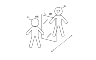
- FIG. 2 is a schematic diagram showing an example of a positional relationship between the display device shown in FIG. 1 and a user
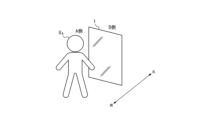
- FIG. 3 is a schematic diagram showing another example of the positional relationship between the display device shown in FIG. 1 and the user
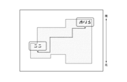
- FIG. FIG. 4 is a schematic diagram showing an example of a reference image
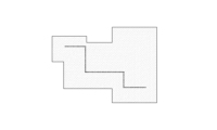
- 3B is a schematic diagram showing an example of a base part included in the reference image shown in FIG. 3A
- FIG. 3B is a schematic diagram showing an example of an icon portion included in the reference image shown in FIG. 3A
- FIG. FIG. 4 is a diagram for explaining a state in which the reference image shown in FIG.
- FIG. FIG. 6B is a diagram for explaining a state in which the map image shown in FIG. 6A is viewed from the other side of the display device;
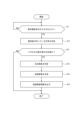
- 2 is a flow chart showing an example of an operation in the control device shown in FIG. 1;
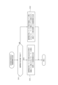
- FIG. 8 is a flowchart showing a detailed example of an operation of determining a target screen and generating a map image shown in FIG. 7;
- FIG. FIG. 4 is a schematic diagram showing an image in which only the icon portion is inverted in the reference image shown in FIG. 3;
- FIG. 9B is a diagram for explaining a state in which the image shown in FIG. 9A is viewed from the other side of the display device; It is a hardware block diagram of a control device.
- the control system 100 includes a display device 1, a detection device 2, a content information generation device 3, and a control device 4.
- the display device 1 is configured by a transparent display.
- the display device 1 displays an image (content) indicated by image information output from the control device 4 .
- the display device 1 can display a map image indicated by map image information, which will be described later in detail.
- the transparent display that constitutes the display device 1 is formed of a plate-like transparent member, and therefore has one display surface and the other display surface opposite to the display surface.
- one predetermined display surface of the display device 1 is referred to as a "reference surface”
- the other display surface is referred to as an "opposite surface”. That is, the display device 1 is configured by a transparent display having a reference surface that is a predetermined display surface on one side and an opposite surface that is a display surface on the opposite side of the reference surface.
- a user UA exists on the side of the reference surface of the display device 1 (A side), and a user U A exists on the opposite side of the display device 1 (B side). B exists.
- the user UA exists on the side of the reference surface of the display device 1 (side A), and the user UA exists on the side of the opposite surface of the display device 1 (side B). person does not exist.
- the detection device 2 includes a thermosensor 21 , a ranging sensor 22 and a geomagnetic sensor 23 .
- the thermosensor 21 , distance measuring sensor 22 , and geomagnetic sensor 23 are provided at known positions with respect to the display device 1 .
- the thermosensor 21 , the ranging sensor 22 and the geomagnetic sensor 23 may be attached to the display device 1 .
- the thermosensor 21, the distance measuring sensor 22, and the geomagnetic sensor 23 may be configured integrally, or may be configured separately from each other.
- the thermosensor 21 measures the temperature of the environment surrounding the display device 1 . Then, the thermosensor 21 outputs temperature information indicating the temperature distribution in the surrounding environment measured by the thermosensor 21 to the control device 4 .
- Thermosensor 21 may output temperature information to control device 4 via a communication network. In an example in which the thermosensor 21 is integrated with the control device 4, the thermosensor 21 can output temperature information to the control device 4 without going through a communication network.
- the distance sensor 22 measures the distance and direction from the display device 1 to the object. Objects whose distance and direction from the display device 1 are measured by the ranging sensor 22 include people. In a configuration in which the distance sensor 22 is attached to the display device 1, the distance sensor 22 measures the distance and direction from the distance sensor 22 to the object as the distance and direction from the display device 1 to the object. do. The distance measurement sensor 22 outputs distance measurement information indicating the distance and direction from the display device 1 to the object measured by the distance measurement sensor 22 to the control device 4 .
- the ranging sensor 22 may output ranging information to the control device 4 via a communication network. Further, in an example where the distance measurement sensor 22 is configured integrally with the control device 4, the distance measurement sensor 22 can output distance measurement information to the control device 4 without going through a communication network.
- the geomagnetic sensor 23 measures geomagnetism and outputs geomagnetic information indicating the direction of the geomagnetism to the control device 4 .
- the geomagnetic sensor 23 may, for example, measure components of geomagnetism in the X-axis, Y-axis, and Z-axis directions in the orthogonal coordinate system of the geomagnetic sensor 23 .
- the geomagnetic information can be information indicating each of the components.
- the geomagnetic sensor 23 may output geomagnetic information to the control device 4 via a communication network. Further, in an example in which the geomagnetic sensor 23 is integrated with the control device 4, the geomagnetic sensor 23 can output distance measurement information to the control device 4 without going through a communication network.
- the content information generation device 3 may be configured by a computer having a memory, a controller, and an output interface.
- the memory may be composed of HDD (Hard Disk Drive), SSD (Solid State Drive), EEPROM (Electrically Erasable Programmable Read-Only Memory), ROM (Read-Only Memory), RAM (Random Access Memory), and the like.
- the controller may be composed of dedicated hardware such as ASIC (Application Specific Integrated Circuit) or FPGA (Field-Programmable Gate Array), may be composed of a processor, or may be composed of both. good.
- the input interface can be a pointing device, keyboard, mouse, or the like.
- the input interface may also be an interface that accepts input of information received by the communication interface. Standards such as Ethernet (registered trademark), FDDI (Fiber Distributed Data Interface), and Wi-Fi (registered trademark) may be used for the communication interface.
- the content information generating device 3 generates reference image information indicating a reference image.
- the reference image is displayed on the display device 1 in a state in which the reference surface (the surface on the A side in the examples of FIGS. 2A and 2B) faces a predetermined direction (the south direction in the examples of FIGS. 2A and 2B). It is an image configured so that the user UA on the side of the reference plane (the side A in the examples of FIGS. 2A and 2B) can appropriately recognize it when the reference plane is viewed.
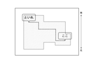
- the reference image is an image showing a map as shown in FIG. 3 as an example. As shown in FIG. 3, the reference image includes a base portion for showing the route on the map, as shown in FIG. 4A.
- the base part can include the shape of the facility in plan view (dots in FIGS. 3 and 4A) and the route from the current location to the predetermined facility in the facility (broken line in FIGS. 3 and 4A).
- the reference image may further include an icon portion for describing facilities on the map superimposed on the base portion, as shown in FIG. 4B.
- the icon section consists of a first icon (“here” in FIGS. 3 and 4B) for explaining a location corresponding to the current location on the map, and a second icon for explaining a location corresponding to a predetermined facility on the map. icon (“put in” in FIGS. 3 and 4B).
- the reference image as shown in FIG. 3 is displayed on the reference surface of the transparent display constituting the display device 1 (for example, the display surface on the side A in FIGS. 2A and 2B), the side of the reference surface (side A) As shown in FIG. 3 , the current location (“here") is located on the upper left of the map, and the predetermined facility (“tore") is located on the lower right.
- the upper side of the map indicated by the map image generally corresponds to the forward direction of the user. In this example, the upper side on the map corresponds to the north direction, which is the forward direction of the user UA shown in FIGS. 2A and 2B. Therefore, by visually recognizing the map image shown in FIG.
- the user UA can easily understand that the predetermined facility is located in the right rear direction of the user UA.
- the user UB who is present on the opposite side (B side) shown in FIG. A map image is viewed on which the facility is located.
- the north direction which is the upper side on the map, corresponds to the back direction of the user UB . Therefore, even though the predetermined facility is located in the front left direction of the user UB , the user UB may misunderstand that the predetermined facility is located in the left rear direction of the user UB. .
- the characters indicated by the icon portion are viewed in reverse, the characters are difficult for the user UB to recognize.
- the control device 4 includes an input unit 41 , a person determination unit 42 , a direction determination unit 43 , a content generation unit 44 and an output unit 45 .
- the input unit 41 is configured by an input interface.
- the person determination unit 42, direction determination unit 43, and content generation unit 44 are configured by a controller.
- the output unit 45 is configured by an output interface.
- the output interface is an interface for outputting information to the display device 1 .
- the input unit 41 receives input of temperature information indicating the temperature distribution in the surrounding environment of the display device 1 and ranging information indicating the distance and direction from the display device 1 to an object.
- the input unit 41 also receives input of geomagnetic information indicating the direction of the geomagnetism detected by the geomagnetic sensor 23 .
- the input unit 41 also receives input of reference image information indicating a reference image generated by the content information generation device 3 .
- the input unit 41 may receive input of reference image information transmitted from the content information generating device 3 via the communication network. Further, the input unit 41 may accept the input of the reference image information by reading the reference image information from the storage medium storing the reference image information generated by the content information generating device 3 .
- the input unit 41 does not have to accept the input of the reference image information.
- the control device 4 has a function of generating reference image information.
- the input unit 41 does not have to accept input of temperature information, ranging information, or geomagnetism information.
- the control device 4 has a function of detecting temperature, a function of measuring distance, or a function of detecting geomagnetism.
- the person determination unit 42 determines which of the reference surface and the opposite surface of the display device 1 is the target surface.
- the attention plane is the display plane on the side where the person closest to the display device 1 exists.
- the human determination unit 42 may determine which of the reference surface and the opposite surface of the display device 1 is the attention surface based on the temperature information or the distance measurement information.
- the person determination unit 42 determines whether or not any of the display surfaces is the target surface. is the plane of interest.
- the person determination unit 42 determines which of the reference surface and the opposite surface of the display device 1 is the target surface based on the temperature information.
- the person determination unit 42 regards a person-shaped object having a temperature within a predetermined range as a person, and determines whether or not there is a person on the side of each display surface.
- the person determining unit 42 determines that the display surface on which the person exists is the target surface. For example, when determining that a person exists only on the reference plane side of the display device 1, the human determination unit 42 determines that the reference plane is the attention plane. Further, when determining that a person exists only on the opposite side of the display device 1, the person determining unit 42 determines that the opposite side is the target surface.
- the person determination unit 42 determines that a person exists on both display surface sides of the display device 1, the person determination unit 42 focuses on the display surface on the side where the human-shaped object is considered to be a person. determined to be a surface. For example, when the person determining unit 42 determines that the human-shaped object existing on the reference plane side is larger than the human-shaped object existing on the opposite side, the human determination unit 42 determines that the reference plane is the target plane. judge. When the person determining unit 42 determines that the human-shaped object existing on the opposite side is larger than the human-shaped object existing on the reference plane side, the opposite plane is the target plane. I judge.
- the person determination unit 42 determines which of the reference surface and the opposite surface of the display device 1 is the surface of interest based on the distance measurement information.
- the person determination unit 42 determines whether or not an object exists within a predetermined distance (for example, 1 meter) from each display surface on the side of each display surface based on the distance measurement information. .
- a predetermined distance for example, 1 meter
- the display surface on the side where the object exists is the target surface. Determine that there is.
- the person determining unit 42 determines that the reference plane is the plane of interest. Further, when determining that an object exists only on the opposite surface side within a predetermined distance from the display device 1, the person determination unit 42 determines that the opposite surface is the target surface.
- the human determination unit 42 displays the image on the side where the object is closer to the display surface.
- the surface is determined to be the target surface. For example, when the person determination unit 42 determines that an object existing on the side of the reference plane is closer than an object existing on the side of the opposite plane, the human determination unit 42 determines that the reference plane is the plane of interest. Further, when determining that the object present on the opposite side is closer than the object present on the reference plane side, the person determination unit 42 determines that the opposite plane is the target plane.
- the person determination unit 42 determines which of the reference surface and the opposite surface of the display device 1 is the target surface based on the temperature information and the distance measurement information.
- the person determining unit 42 regards an object having a temperature within a predetermined range and having the shape of a person as a person, based on the temperature information. exists. Then, when determining that a person exists only on one of the display surface sides, the person determination unit 42 determines whether or not the distance from the display surface to the person is within a predetermined distance based on the distance measurement information. . When the person determination unit 42 determines that the distance from the display surface to the person is within a predetermined distance, the person determination unit 42 determines that the display surface on which the person exists is the target surface.
- the person determination unit 42 determines that a person exists on both display surface sides, based on the distance measurement information, the person determination unit 42 displays a display on the side where the person is present who is at a smaller distance from the display surface and is within a predetermined distance.
- the surface is determined to be the target surface. If there is no person within a predetermined distance from the display surface on either display surface side, the person determination unit 42 determines that none of the display surfaces is the surface of interest.
- the direction determination unit 43 determines the direction of the reference plane based on the direction of geomagnetism detected by the geomagnetic sensor 23 provided at a known position with respect to the display device 1 .
- the content generation unit 44 uses the reference image to generate a map image showing a map, based on which of the reference surface and the opposite surface is the surface of interest and the direction in which the reference surface is facing.
- the content generator 44 generates a map using the base portion included in the reference image.
- the reference image further includes an icon portion
- the content generator 44 may further use the icon portion to generate the map image.
- the content generation unit 44 sets the direction opposite to the direction in which the reference plane faces (that is, the direction viewed by the person closest to the display plane).
- a map image is generated in which the base part is arranged so that the is on the upper side on the map.
- the content generation unit 44 can generate a map image in which the base portion is arranged such that the north direction, which is the direction opposite to the south direction, faces upward, as shown in FIG.
- the content generation portion 44 when the reference surface is determined to be the target surface, the content generation portion 44 further moves the icon portion to the corresponding position of the base portion without inverting the icon portion.
- a map image superimposed on the base portion may be generated.
- the content generation unit 44 determines that the west direction, which is the direction opposite to the east direction, is the upper side.
- a map image is generated in which the base portion is arranged as follows. At this time, the content generation unit 44 may further generate a map image superimposed on the base portion without inverting the icon portion at the corresponding position of the base portion.
- the content generation unit 44 rotates clockwise from the north direction.
- a map image is generated in which the base portion is arranged such that the direction opposite to the direction shifted by ⁇ ° faces upward. At this time, the content generation unit 44 may further generate a map image superimposed on the base portion without inverting the icon portion at the corresponding position of the base portion.
- the content generation unit 44 determines that the opposite surface is the target surface
- the direction in which the reference surface is facing is the upper side on the map.
- a map image is generated in which an inverted base portion is arranged by vertically inverting the base portion.
- the content generation unit 44 As shown in FIG. 6A, an inverted base portion is arranged by vertically inverting the base portion so that the south direction faces upward, and the icon portion is horizontally inverted at the corresponding position of the base portion. can be used to generate a map image superimposed on the base portion.
- the content generation unit 44 when the opposite surface is determined to be the target surface, the content generation unit 44 further horizontally inverts the icon portion at the corresponding position of the inversion base portion. may be used to generate a map image superimposed on the base portion.
- the control device 4 outputs map image information indicating a map image as shown in FIG. 6A to the display device 1, and when the display device 1 displays the map image indicated by the map image information, the opposite side (FIG. 2A) is displayed.
- the map image as shown in FIG. 6B is visually recognized by the user UB on the side B ) . Thereby, the user UB can appropriately understand that the predetermined facility is located in the front left direction of the user UB.
- the content generation unit 44 flips the base part upside down so that the east direction faces upward.
- a map image is generated in which the inverted base portion is arranged.
- the content generating unit 44 may further generate a map image in which the icon portion is horizontally reversed and superimposed on the reverse base portion at a position corresponding to the reverse base portion.
- the content generation unit 44 rotates clockwise from the north direction.
- a map image is generated in which a reversed base portion is arranged so that the direction shifted by ⁇ ° faces upward.
- the content generating unit 44 may further reverse the icon portion horizontally at the corresponding position of the reverse base portion to generate a map image superimposed on the reverse base portion.
- the output unit 45 outputs map image information indicating the map image to the display device 1 .
- the output unit 45 may output map image information via a communication network.
- the map image information may be output without going through the communication network.
- FIG. 7 and 8 are flowcharts showing an example of the operation of the control device 4 according to this embodiment.
- the operation of the control device 4 described with reference to FIGS. 7 and 8 is based on the present embodiment with respect to a predetermined display surface on one side, which is a reference surface, and a display surface on the opposite side of the reference surface, which is an opposite surface. It corresponds to an example of a control method of the control device 4 configured by a transparent display having
- the direction determination unit 43 determines whether or not an input of an operation start command for starting an operation has been received.
- the operation start command may be input by the user's operation of the display device 1, for example.
- the operation may be, for example, pressing a button, switching a switch, or inputting using a keyboard. Further, the operation may be movement of the display device 1 by the user.
- any sensor capable of detecting the movement of the display device 1, such as a motion sensor, a speed sensor, or a direction sensor detects the movement of the display device 1, an operation start command is input.
- step S11 When it is determined in step S11 that the input of the operation start command has not been accepted, the direction determination unit 43 returns to step S11 and repeats the process.
- step S12 the direction determining unit 43 determines the direction of the reference plane based on the direction of the geomagnetism detected by the geomagnetic sensor 23. judge.
- step S13 the person determination unit 42 determines whether or not any display surface is the surface of interest.
- step S13 If it is determined in step S13 that none of the display surfaces is the surface of interest, the control device 4 terminates the process.
- step S14 the person determination unit 42 determines which of the reference surface and the opposite surface of the display device 1 is the closest person to the display device 1. is the target surface, which is the display surface on the side where is present.
- step S15 the content generation unit 44 generates a map image showing a map using the reference image based on which of the reference surface and the opposite surface is the surface of interest and the direction in which the reference surface is facing. .
- step S14 the person determination unit 42 determines whether or not the reference plane is the target plane.
- step S151 the content generation section 44 moves the base section so that the direction opposite to the direction in which the reference plane faces is the upper side on the map. Generate the placed map image. At this time, the content generation unit 44 may further generate a map image superimposed on the base portion at the corresponding position of the base portion without inverting the icon portion.
- step S152 the content generation unit 44 determines that the direction in which the reference plane is facing is the upper side on the map.
- a map image is generated in which an inverted base portion is arranged so that the base portion is vertically inverted.
- the content generation unit 44 may further reverse the icon portion horizontally at the corresponding position of the reverse base portion to generate a map image superimposed on the base portion.
- step S16 the output unit 45 outputs map image information indicating the map image to the display device 1.
- the control device 4 determines that either the reference surface or the opposite surface of the display device 1 is the attention screen, which is the display surface on which the person closest to the display device 1 exists.
- a map image showing a map is generated using the reference image based on the person determination unit 42 that determines whether the reference surface or the opposite surface is the target screen and the direction in which the reference surface is facing.
- a content generation unit 44 and an output unit 45 for outputting map image information indicating a map image to the display device 1 are provided. Thereby, the control device 4 can allow the user of the display device 1 to visually recognize an appropriate map image.
- the reference image includes a base portion for indicating the route on the map, and the content generation unit 44 determines that the reference surface is facing when it is determined that the reference surface is the target screen.
- a map image is generated in which the base portion is arranged so that the direction opposite to the direction is the upper side on the map.
- a map image is generated in which an inverted base portion is arranged so that the base portion is vertically inverted so as to be on the upper side.
- the opposite surface is determined to be the reference surface
- a configuration in which an image in which only the icon portion is inverted is generated without changing the orientation of the base portion as shown in FIG. 9A will be considered.
- the display device 1 displays the image
- the user UB present on the B side of the display device 1 will see the direction in which he/she is facing (south in the example shown in FIG. 2A) as shown in FIG. 9B.
- the direction of ) will be referred to the map shown on the bottom. Therefore, it becomes difficult for the user UB to understand the map.
- the control device 4 of the present embodiment determines that the opposite surface is the reference surface, as described with reference to FIGS.
- the direction ( A map image is generated in which the south direction in the example shown in FIG. 2A is shown on the upper side of the map. Therefore, as described above, there is an effect that the user UB present on the opposite side (B side in the example of FIG. 2A) can easily understand the map.
- the reference image further includes an icon portion for explaining facilities on the map superimposed on the base portion, and the content generation unit 44 determines that the target screen is the reference surface.
- a map image is generated in which the icon portion is superimposed on the base portion without being reversed at a corresponding position of the base portion. At the corresponding position, the icon portion is horizontally inverted to generate a map image superimposed on the inverted base portion.
- the direction determination unit determines the direction of the reference plane based on the direction of the geomagnetism detected by the geomagnetic sensor 23 provided at a known position with respect to the display device 1. 43.
- the control device 4 allows the user of the display device 1 to view an appropriate map image. can.
- control device 4 does not have to include the azimuth determining section 43 .
- the control device 4 does not include the azimuth determination unit 43 .
- the control device 4 does not execute step S12 in the control method described with reference to FIGS.
- step S11 not the azimuth determination unit 43 but the person determination unit 42 determines whether or not an operation start command has been input.
- FIG. 10 is a block diagram showing a schematic configuration of a computer 101 each functioning as the control device 4.
- the computer 101 may be a general-purpose computer, a dedicated computer, a workstation, a PC (Personal Computer), an electronic notepad, or the like.
- Program instructions may be program code, code segments, etc. for performing the required tasks.
- the computer 101 includes a processor 110, a ROM (Read Only Memory) 120, a RAM (Random Access Memory) 130, a storage 140, an input unit 150, a display unit 160, and a communication interface ( I/F) 170.
- the processor 110 is specifically a CPU (Central Processing Unit), MPU (Micro Processing Unit), GPU (Graphics Processing Unit), DSP (Digital Signal Processor), SoC (System on a Chip), etc. may be configured by a plurality of processors of
- the processor 110 controls each component and executes various arithmetic processes. That is, processor 110 reads a program from ROM 120 or storage 140 and executes the program using RAM 130 as a work area. The processor 110 performs control of each configuration and various arithmetic processing according to programs stored in the ROM 120 or the storage 140 . In the above-described embodiment, the ROM 120 or storage 140 stores the program according to the present disclosure.
- the program may be stored in a storage medium readable by the computer 101. By using such a storage medium, it is possible to install the program in the computer 101 .
- the storage medium storing the program may be a non-transitory storage medium.
- the non-temporary storage medium is not particularly limited, but may be, for example, a CD-ROM, a DVD-ROM, a USB (Universal Serial Bus) memory, or the like.
- this program may be downloaded from an external device via a network.
- the ROM 120 stores various programs and various data.
- RAM 130 temporarily stores programs or data as a work area.
- the storage 140 is configured by a HDD (Hard Disk Drive) or SSD (Solid State Drive) and stores various programs including an operating system and various data.
- the input unit 150 includes one or more input interfaces that receive user's input operations and acquire information based on the user's operations.
- the input unit 150 is a pointing device, keyboard, mouse, etc., but is not limited to these.
- the display unit 160 includes one or more output interfaces that output information.
- the display unit 160 is a display that outputs information as video or a speaker that outputs information as audio, but is not limited to these.
- the display unit 160 also functions as the input unit 150 when it is a touch panel type display.
- a communication interface (I/F) 170 is an interface for communicating with an external device.
- a reference plane which is a predetermined one side display side, and an opposite side, which is a display side opposite to the reference plane, comprising a memory, at least one controller connected to the memory, and an output interface, the controller
- the output interface is a control device that outputs map image information indicating the map image to the display device.
- the reference image includes a base portion for indicating a route on the map;
- the controller is generating a map image in which the base portion is arranged such that a direction opposite to the direction in which the reference surface is directed is the upper side on the map when the reference surface is determined to be the target screen;
- the reference image further includes an icon portion for explaining facilities on the map, superimposed on the base portion,
- the controller is when the reference plane is determined to be the attention screen, further generating the map image superimposed on the base portion without inverting the icon portion at a corresponding position of the base portion;
- the map image superimposed on the reversal base is generated by horizontally reversing the icon portion at a corresponding position of the reversal base.
- the controller according to any one of additional items 1 to 3, wherein the controller determines which of the reference surface and the opposite surface of the display device is the target screen based on the temperature information or the ranging information.
- Control device as described.
- (Appendix 5) Any one of additional items 1 to 4, wherein the controller determines the direction of the reference plane based on the direction of geomagnetism detected by a geomagnetic sensor provided at a known position with respect to the display device. or the control device according to claim 1.
- Appendix 6 A control method executed by a control device that controls a display device configured by a transparent display having a reference surface that is a predetermined display surface on one side and an opposite surface that is a display surface on the opposite side of the reference surface.
- Control method including. (Appendix 7) A non-temporary storage medium storing a computer-executable program, the non-temporary storage medium storing a program that causes the computer to function as the control device according to any one of additional items 1 to 5.
Landscapes
- Engineering & Computer Science (AREA)
- Physics & Mathematics (AREA)
- Theoretical Computer Science (AREA)
- Mathematical Physics (AREA)
- Business, Economics & Management (AREA)
- Educational Administration (AREA)
- Educational Technology (AREA)
- General Physics & Mathematics (AREA)
- Controls And Circuits For Display Device (AREA)
Abstract
本開示に係る制御装置(4)は、基準面と反対面とを有する透明ディスプレイによって構成されている表示装置(1)を制御する制御装置(4)であって、基準面及び反対面のいずれが注目画面であるかを判定する人判定部(42)と、基準面及び反対面のいずれが注目画面であるかと、基準面が向いている方角とに基づいて、基準画像を用いて地図画像を生成するコンテンツ生成部(44)と、地図画像情報を表示装置に出力する出力部(45)と、を備える。
Description
本開示は、制御装置、制御方法、及びプログラムに関する。
近年、背景が透けている透明ディスプレイが商品化されている。透明ディスプレイは、一方の面及び他方の面の両方の側で利用者にコンテンツを視認させることができる。そのため、透明ディスプレイは、該透明ディスプレイを間に挟んで相対する複数人の人同士のコミュニケーションに活用されることが期待されている。
"See-Through Captions"、Digital Nature Group、[online]、2021年2月10日、[令和3年12月13日検索]、インターネット<URL:https://digitalnature.slis.tsukuba.ac.jp/2021/02/see-through-captions/>
しかしながら、透明ディスプレイに表示されるコンテンツにおいて、一方側から視認された状態と、他方側から視認された状態とが異なることがある。この場合、透明ディスプレイが、一方側から視認されたときに意味が通じ得るようにコンテンツを表示させると、他方側から該コンテンツが視認されたときに意味が通じなくなることがある。
例えば、透明ディスプレイの一方側にいる利用者に適切に視認されるように、該透明ディスプレイにコンテンツが表示されたとき、該透明ディスプレイの他方側にいる利用者には該コンテンツは適切に視認されないことがある。そのため、利用者は、適切にコンテンツを視認できる側から透明ディスプレイを視認する必要がある。また、複数の利用者が、透明ディスプレイを間に挟んで相対する場合、一方側の利用者は適切にコンテンツを視認することができても、他方側にいる利用者は適切にコンテンツを視認することができないことがある。
かかる事情に鑑みてなされた本開示の目的は、表示装置の利用者に適切なコンテンツを視認させることができる制御装置、制御方法、及びプログラムを提供することにある。
上記課題を解決するため、本開示に係る制御装置は、所定の一方側の表示面である基準面と、該基準面の反対側の表示面である反対面とを有する透明ディスプレイによって構成されている表示装置を制御する制御装置であって、前記表示装置における前記基準面及び前記反対面のいずれが、前記表示装置に最も近い人が存在する側の表示面である注目画面であるかを判定する人判定部と、前記基準面及び前記反対面のいずれが前記注目画面であるかと、前記基準面が向いている方角とに基づいて、基準画像を用いて、地図を示す地図画像を生成するコンテンツ生成部と、前記地図画像を示す地図画像情報を前記表示装置に出力する出力部と、を備える。
また、上記課題を解決するため、本開示に係る制御方法は、所定の一方側の表示面である基準面と、該基準面の反対側の表示面である反対面とを有する透明ディスプレイによって構成されている表示装置を制御する制御装置が実行する制御方法であって、前記表示装置における前記基準面及び前記反対面のいずれが、前記表示装置に最も近い人が存在する側の表示面である注目画面であるかを判定するステップと、前記基準面及び前記反対面のいずれが前記注目画面であるかと、前記基準面が向いている方角とに基づいて、基準画像を用いて、地図を示す地図画像を生成するステップと、前記地図画像を示す地図画像情報を前記表示装置に出力するステップと、を含む。
また、上記課題を解決するため、本開示に係るプログラムは、コンピュータを上述した制御装置として機能させる。
本開示に係る制御装置、制御方法、及びプログラムによれば、表示装置の利用者に適切なコンテンツを視認させることができる。
図1に示すように、本実施形態に係る制御システム100は、表示装置1と、検出装置2と、コンテンツ情報生成装置3と、制御装置4とを備える。
<表示装置の構成>
表示装置1は、透明ディスプレイによって構成されている。表示装置1は、制御装置4から出力された画像情報が示す画像(コンテンツ)を表示する。本実施形態において、表示装置1は、追って詳細に説明する、地図画像情報が示す地図画像を表示することができる。表示装置1を構成する透明ディスプレイは、板状の透明な部材によって形成されており、そのため、一方の表示面と、該表示面の反対側である他方側の表示面とを有する。本実施形態では、表示装置1における所定の一方の表示面を「基準面」といい、他方側の表示面を「反対面」という。すなわち、表示装置1は、所定の一方側の表示面である基準面と、該基準面の反対側の表示面である反対面とを有する透明ディスプレイによって構成されている。
表示装置1は、透明ディスプレイによって構成されている。表示装置1は、制御装置4から出力された画像情報が示す画像(コンテンツ)を表示する。本実施形態において、表示装置1は、追って詳細に説明する、地図画像情報が示す地図画像を表示することができる。表示装置1を構成する透明ディスプレイは、板状の透明な部材によって形成されており、そのため、一方の表示面と、該表示面の反対側である他方側の表示面とを有する。本実施形態では、表示装置1における所定の一方の表示面を「基準面」といい、他方側の表示面を「反対面」という。すなわち、表示装置1は、所定の一方側の表示面である基準面と、該基準面の反対側の表示面である反対面とを有する透明ディスプレイによって構成されている。
図2Aに示す例では、表示装置1の基準面の側(A側)には、利用者UAが存在しており、表示装置1の反対面の側(B側)には、利用者UBが存在している。また、図2Bに示す例では、表示装置1の基準面の側(A側)には、利用者UAが存在しており、表示装置1の反対面の側(B側)には、利用者が存在していない。
<検出装置の構成>
図1に示すように、検出装置2は、サーモセンサ21と、測距センサ22と、地磁気センサ23とを備える。サーモセンサ21、測距センサ22、及び地磁気センサ23は、表示装置1に対して既知の位置に設けられている。例えば、サーモセンサ21、測距センサ22、及び地磁気センサ23は、表示装置1に取り付けられていてもよい。また、サーモセンサ21、測距センサ22、及び地磁気センサ23は一体に構成されていてもよいし、互いに別体として構成されていてもよい。
図1に示すように、検出装置2は、サーモセンサ21と、測距センサ22と、地磁気センサ23とを備える。サーモセンサ21、測距センサ22、及び地磁気センサ23は、表示装置1に対して既知の位置に設けられている。例えば、サーモセンサ21、測距センサ22、及び地磁気センサ23は、表示装置1に取り付けられていてもよい。また、サーモセンサ21、測距センサ22、及び地磁気センサ23は一体に構成されていてもよいし、互いに別体として構成されていてもよい。
サーモセンサ21は、表示装置1の周囲環境の温度を計測する。そして、サーモセンサ21は、該サーモセンサ21によって計測された、周囲環境における温度分布を示す温度情報を制御装置4に出力する。サーモセンサ21は、通信ネットワークを介して温度情報を制御装置4に出力してもよい。また、サーモセンサ21が制御装置4と一体に構成されている例においては、サーモセンサ21は、通信ネットワークを介さずに温度情報を制御装置4に出力することができる。
測距センサ22は、表示装置1から物体までの距離及び方向を測定する。測距センサ22が表示装置1からの距離及び方向を測定する物体は、人を含む。測距センサ22が表示装置1に取り付けられている構成においては、測距センサ22は、該測距センサ22から、物体までの距離及び方向を、表示装置1から物体までの距離及び方向として測定する。そして、測距センサ22は、該測距センサ22によって測定された、表示装置1から物体までの距離及び方向を示す測距情報を制御装置4に出力する。測距センサ22は、通信ネットワークを介して測距情報を制御装置4に出力してもよい。また、測距センサ22が制御装置4と一体に構成されている例においては、測距センサ22は、通信ネットワークを介さずに測距情報を制御装置4に出力することができる。
地磁気センサ23は、地磁気を計測して、該地磁気の方向を示す地磁気情報を制御装置4に出力する。地磁気センサ23は、例えば、地磁気センサ23の直交座標系におけるX軸、Y軸、及びZ軸方向それぞれの地磁気の成分を計測してもよい。このような構成において、地磁気情報は、該成分それぞれを示す情報とすることができる。地磁気センサ23は、通信ネットワークを介して地磁気情報を制御装置4に出力してもよい。また、地磁気センサ23が制御装置4と一体に構成されている例においては、地磁気センサ23は、通信ネットワークを介さずに測距情報を制御装置4に出力することができる。
<コンテンツ情報生成装置の構成>
コンテンツ情報生成装置3は、メモリ、コントローラ、及び出力インターフェースを備えるコンピュータによって構成されてもよい。メモリは、HDD(Hard Disk Drive)、SSD(Solid State Drive)、EEPROM(Electrically Erasable Programmable Read-Only Memory)、ROM(Read-Only Memory)及びRAM(Random Access Memory)等によって構成されてもよい。コントローラは、ASIC(Application Specific Integrated Circuit)、FPGA(Field-Programmable Gate Array)等の専用のハードウェアによって構成されてもよいし、プロセッサによって構成されてもよいし、双方を含んで構成されてもよい。入力インターフェースは、ポインティングデバイス、キーボード、マウス等とすることができる。また、入力インターフェースは、通信インターフェースによって受信された情報の入力を受け付けるインターフェースであってもよい。通信インターフェースには、例えば、イーサネット(登録商標)、FDDI(Fiber Distributed Data Interface)、Wi-Fi(登録商標)等の規格が用いられてもよい。
コンテンツ情報生成装置3は、メモリ、コントローラ、及び出力インターフェースを備えるコンピュータによって構成されてもよい。メモリは、HDD(Hard Disk Drive)、SSD(Solid State Drive)、EEPROM(Electrically Erasable Programmable Read-Only Memory)、ROM(Read-Only Memory)及びRAM(Random Access Memory)等によって構成されてもよい。コントローラは、ASIC(Application Specific Integrated Circuit)、FPGA(Field-Programmable Gate Array)等の専用のハードウェアによって構成されてもよいし、プロセッサによって構成されてもよいし、双方を含んで構成されてもよい。入力インターフェースは、ポインティングデバイス、キーボード、マウス等とすることができる。また、入力インターフェースは、通信インターフェースによって受信された情報の入力を受け付けるインターフェースであってもよい。通信インターフェースには、例えば、イーサネット(登録商標)、FDDI(Fiber Distributed Data Interface)、Wi-Fi(登録商標)等の規格が用いられてもよい。
コンテンツ情報生成装置3は、基準画像を示す基準画像情報を生成する。基準画像は、基準面(図2A及び図2Bの例ではA側の面)が所定の方角(図2A及び図2Bの例では南の方角)を向いている状態で、該表示装置1に表示されたときに、基準面の側(図2A及び図2Bの例ではA側)にいる利用者UAが適切に認識できるように構成されている画像である。基準画像は、一例として図3に示すような、地図を示す画像である。図3に示すように、基準画像は、図4Aに示すような、地図における経路を示すためのベース部を含む。ベース部は、平面視における施設の形状(図3及び図4Aの網点)と、該施設内における現在地から所定の設備までの経路(図3及び図4Aの破線)とを含むことができる。また、図3に示すように、基準画像は、図4Bに示すような、ベース部に重畳させる、地図における設備を説明するためのアイコン部をさらに含むことができる。アイコン部は、地図における現在地に相当する箇所を説明するための第1のアイコン(図3及び図4Bの「ここ」)と、地図における所定の設備に相当する箇所を説明するための第2のアイコン(図3及び図4Bの「といれ」)とを含むことができる。
図3に示すような基準画像が、表示装置1を構成する透明ディスプレイの基準面(例えば、図2A及び図2BのA側の表示面)に表示された場合、基準面の側(A側)に存在している利用者UAには、図3に示すように、地図上の左上に現在地(「ここ」)が位置し、右下に所定の設備(「といれ」)が位置しているように視認される。鉛直方向に平行に配置されている表示面において、地図画像が示す地図上での上側が、利用者の前方向に相当するのが通例である。本例では、地図上での上側が、図2A及び図2Bに示されている利用者UAの前方向である北の方角に相当する。そのため、利用者UAは、図3に示す地図画像を視認することによって、自身の右後ろ方向に所定の設備が位置していることを容易に理解することができる。これに対して、図2Aに示されている反対面の側(B側)に存在している利用者UBには、図5に示すような、右上に現在地が位置し、左下に所定の設備が位置している地図画像が視認される。地図上で上側である北の方角は、利用者UBの後ろ方向に相当する。そのため、利用者UBの左前方向に所定の設備が位置しているにもかかわらず、利用者UBは自身の左後ろ方向に所定の設備が位置していると誤解してしまうことがある。さらに、利用者UBには、アイコン部によって示される文字が反転して視認されるため、文字が認識されにくい。
<制御装置の構成>
図1に示すように、制御装置4は、入力部41と、人判定部42と、方角判定部43と、コンテンツ生成部44と、出力部45とを備える。入力部41は、入力インターフェースによって構成されている。人判定部42、方角判定部43、及びコンテンツ生成部44は、コントローラによって構成されている。出力部45は、出力インターフェースによって構成されている。出力インターフェースは、表示装置1に情報を出力するためのインターフェースである。
図1に示すように、制御装置4は、入力部41と、人判定部42と、方角判定部43と、コンテンツ生成部44と、出力部45とを備える。入力部41は、入力インターフェースによって構成されている。人判定部42、方角判定部43、及びコンテンツ生成部44は、コントローラによって構成されている。出力部45は、出力インターフェースによって構成されている。出力インターフェースは、表示装置1に情報を出力するためのインターフェースである。
入力部41は、表示装置1の周囲環境における温度分布を示す温度情報、及び表示装置1から物体までの距離及び方向を示す測距情報の入力を受け付ける。また、入力部41は、地磁気センサ23によって検出された地磁気の方向を示す地磁気情報の入力を受け付ける。
また、入力部41は、コンテンツ情報生成装置3によって生成された、基準画像を示す基準画像情報の入力を受け付ける。入力部41は、コンテンツ情報生成装置3から通信ネットワークを介して送信された基準画像情報の入力を受け付けてもよい。また、入力部41は、コンテンツ情報生成装置3によって生成された基準画像情報を記憶した記憶媒体から、該基準画像情報を読み出すことによって、該基準画像情報の入力を受け付けてもよい。
なお、入力部41は、基準画像情報の入力を受け付けなくてもよい。入力部41が基準画像情報の入力を受け付けない構成において、制御装置4は、基準画像情報を生成する機能を有する。また、入力部41は、温度情報、測距情報、又は地磁気情報の入力を受け付けなくてもよい。入力部41が温度情報、測距情報、又は地磁気情報の入力を受け付けない構成において、制御装置4が、温度を検出する機能、距離を測定する機能、又は地磁気を検出する機能を有する。
人判定部42は、表示装置1における基準面及び反対面のいずれが注目面であるかを判定する。注目面は、表示装置1に最も近い人が存在する側の表示面である。例えば、人判定部42は、温度情報又は測距情報に基づいて、表示装置1における基準面及び反対面のいずれが注目面であるかを判定してもよい。人判定部42は、いずれかの表示面が注目面であるか否かを判定し、いずれかの表示面が注目面であると判定された場合、表示装置1における基準面及び反対面のいずれが注目面であるかを判定してもよい。
第1例として、人判定部42は、温度情報に基づいて、表示装置1における基準面及び反対面のいずれが注目面であるかを判定する。
具体的には、人判定部42は、所定範囲の温度を有し、人の形状をした物体を人とみなし、各表示面の側に人が存在するか否かを判定する。人判定部42は、表示装置1のいずれかの表示面の側のみに人が存在すると判定した場合、該人が存在する側の表示面が注目面であると判定する。例えば、人判定部42は、表示装置1の基準面の側のみに人が存在すると判定した場合、基準面が注目面であると判定する。また、人判定部42は、表示装置1の反対面の側のみに人が存在すると判定した場合、反対面が注目面であると判定する。
また、人判定部42は、表示装置1の両方の表示面の側に、人が存在すると判定した場合、人であるとみなした、人の形状をした物体がより大きい側の表示面が注目面であると判定する。例えば、人判定部42は、基準面側に存在する人の形状をした物体が、反対面の側に存在する人の形状をした物体より大きいと判定した場合、基準面が注目面であると判定する。また、人判定部42は、反対面の側に存在する人の形状をした物体が、基準面の側に存在する人の形状をした物体より大きいと判定した場合、反対面が注目面であると判定する。
第2例において、人判定部42は、測距情報に基づいて、表示装置1における基準面及び反対面のいずれが注目面であるかを判定する。
具体的には、人判定部42は、測距情報に基づいて、各表示面の側の、それぞれの表示面から所定距離(例えば、1メートル)以内に物体が存在するか否かを判定する。人判定部42は、表示装置1のいずれかの表示面の側のみにおいて、該表示装置1から所定距離以内に物体が存在すると判定した場合、該物体が存在する側の表示面が注目面であると判定する。例えば、人判定部42は、基準面の側のみに表示装置1から所定距離以内に物体が存在すると判定した場合、基準面が注目面であると判定する。また、人判定部42は、反対面の側のみに表示装置1から所定距離以内に物体が存在すると判定した場合、反対面が注目面であると判定する。
また、人判定部42は、表示装置1の両方の表示面の側において、該表示面から所定距離以内に物体が存在すると判定した場合、表示面からの距離が近い物体が存在する側の表示面が注目面であると判定する。例えば、人判定部42は、基準面の側に存在する物体が、反対面の側に存在する物体より近いと判定した場合、基準面が注目面であると判定する。また、人判定部42は、反対面の側に存在する物体が、基準面の側に存在する物体より近いと判定した場合、反対面が注目面であると判定する。
第3例では、人判定部42は、温度情報及び測距情報に基づいて、表示装置1における基準面及び反対面のいずれが注目面であるかを判定する。
具体的には、人判定部42は、第1例と同様に、温度情報に基づいて、所定範囲の温度を有し、人の形状をした物体を人とみなし、各表示面の側に人が存在するか否かを判定する。そして、人判定部42は、いずれかの表示面の側のみに人が存在すると判定すると、測距情報に基づいて、表示面から人までの距離が所定距離以内であるか否かを判定する。人判定部42は、表示面から人までの距離が所定距離以内であると判定すると、人が存在する側の表示面が注目面であると判定する。
また、人判定部42は、両方の表示面の側に人が存在すると判定すると、測距情報に基づいて、表示面からの距離が小さく、かつ所定距離以内である人が存在する側の表示面が注目面であると判定する。また、人判定部42は、いずれの表示面の側にも表示面からの距離が所定距離以内である人が存在しない場合、いずれの表示面も注目面ではないと判定する。
方角判定部43は、表示装置1に対して既知の位置に設けられている地磁気センサ23によって検出された地磁気の方向に基づいて、基準面が向いている方角を判定する。
コンテンツ生成部44は、基準面及び反対面のいずれが注目面であるかと、基準面が向いている方角とに基づいて、基準画像を用いて、地図を示す地図画像を生成する。コンテンツ生成部44は、基準画像に含まれるベース部を用いて地図を生成する。基準画像がさらにアイコン部を含む構成においては、コンテンツ生成部44は、さらにアイコン部を用いて地図画像を生成してもよい。
具体的には、コンテンツ生成部44は、基準面が注目面であると判定された場合、基準面が向いている方角の反対の方角(すなわち、表示面に最も近い人が見ている方角)が地図上で上側となるようにベース部を配置した地図画像を生成する。図2A及び図2Bに示すようなA側の表示面が基準面である例において、基準面が南の方角を向いていて、基準面が注目面であると判定された場合、コンテンツ生成部44は、図3に示すように、南の方角の反対の方角である北の方角が上側となるようにベース部を配置した地図画像を生成することができる。
基準画像が、アイコン部をさらに含む構成においては、コンテンツ生成部44は、基準面が注目面であると判定された場合、さらに、該ベース部の対応する位置に、アイコン部を反転させずにベース部に重畳させた地図画像を生成してもよい。
また、基準面が、例えば東の方角を向いていて、基準面が注目面であると判定された場合、コンテンツ生成部44は、東の方角の反対の方角である西の方角が上側となるようにベース部を配置した地図画像を生成する。このとき、コンテンツ生成部44は、さらに、該ベース部の対応する位置に、アイコン部を反転させずにベース部に重畳させた地図画像を生成してもよい。同様にして、例えば、基準面が北の方角から時計回りにα°ずれた方角を向いていて、基準面が注目面であると判定された場合、コンテンツ生成部44は、北の方角から時計回りにα°ずれた方角の反対の方角が上側となるようにベース部を配置した地図画像を生成する。このとき、コンテンツ生成部44は、さらに、該ベース部の対応する位置に、アイコ部ンを反転させずにベース部に重畳させた地図画像を生成してもよい。
また、コンテンツ生成部44は、反対面が注目面であると判定された場合、基準面が向いている方角(すなわち、表示面に最も近い人が見ている方角)が地図上で上側となるように、ベース部を上下に反転させた反転ベース部を配置した地図画像を生成する。図2A及び図2Bに示すようなA側の表示面が基準面である例において、基準面が南の方角を向いていて、反対面が注目面であると判定された場合、コンテンツ生成部44は、図6Aに示すように、南の方角が上側となるように、ベース部を上下に反転させた反転ベース部を配置し、該ベース部の対応する位置に、アイコン部を左右に反転させて、ベース部に重畳させた地図画像を生成することができる。
基準画像が、アイコン部を含む構成においては、コンテンツ生成部44は、反対面が注目面であると判定された場合、さらに、該反転ベース部の対応する位置に、アイコン部を左右に反転させて、ベース部に重畳させた地図画像を生成してもよい。
制御装置4が、図6Aに示すような地図画像を示す地図画像情報を表示装置1に出力し、表示装置1が、該地図画像情報が示す地図画像を表示すると、反対面の側(図2Aの例ではB側)にいる利用者UBには、図6Bに示すような地図画像が視認される。これにより、利用者UBは、自身の左前方向に所定の設備が位置していることを適切に理解することができる。
また、基準面が、例えば東の方角を向いていて、反対面が注目面であると判定された場合、コンテンツ生成部44は、東の方角が上側となるように、ベース部を上下に反転させた反転ベース部を配置した地図画像を生成する。このとき、コンテンツ生成部44は、さらに、該反転ベース部の対応する位置に、アイコン部を左右に反転させて反転ベース部に重畳させた地図画像を生成してもよい。同様にして、例えば、基準面が北の方角から時計回りにα°ずれた方角を向いていて、反対面が注目面であると判定された場合、コンテンツ生成部44は、北の方角から時計回りにα°ずれた方角が上側となるように、ベース部を上下に反転させた反転ベース部を配置した地図画像を生成する。このとき、コンテンツ生成部44は、さらに、該反転ベース部の対応する位置に、アイコン部を左右に反転させて、反転ベース部に重畳させた地図画像を生成してもよい。
出力部45は、地図画像を示す地図画像情報を表示装置1に出力する。具体的には、出力部45は、通信ネットワークを介して地図画像情報を出力してもよい。また、表示装置1が制御装置4と一体に構成されている例において、通信ネットワークを介さずに地図画像情報を出力してもよい。
<制御装置の動作>
ここで、本実施形態に係る制御装置4の動作について、図7及び図8を参照して説明する。図7及び図8は、本実施形態に係る制御装置4の動作の一例を示すフローチャートである。図7及び図8を参照して説明する制御装置4における動作は本実施形態に係る、所定の一方側の表示面である基準面と、該基準面の反対側の表示面である反対面とを有する透明ディスプレイによって構成されている制御装置4の制御方法の一例に相当する。
ここで、本実施形態に係る制御装置4の動作について、図7及び図8を参照して説明する。図7及び図8は、本実施形態に係る制御装置4の動作の一例を示すフローチャートである。図7及び図8を参照して説明する制御装置4における動作は本実施形態に係る、所定の一方側の表示面である基準面と、該基準面の反対側の表示面である反対面とを有する透明ディスプレイによって構成されている制御装置4の制御方法の一例に相当する。
図7に示すように、ステップS11において、方角判定部43が、動作を開始するための動作開始命令の入力が受け付けられたか否かを判定する。動作開始命令は、例えば、表示装置1の利用者の操作によって入力されてもよい。操作は、例えば、ボタンの押下、スイッチの切り替え、キーボードによる入力であってもよい。また、操作は、利用者による表示装置1の移動であってもよい。このような構成においては、例えば、表示装置1の移動を検出可能な、モーションセンサ、速度センサ、方向センサ等の任意のセンサが、該表示装置1の移動を検出すると、動作開始命令が入力されてもよい。
ステップS11で、動作開始命令の入力が受け付けられていないと判定されると、方角判定部43が、再びステップS11に戻って処理を繰り返す。
ステップS11で、動作開始命令の入力が受け付けられたと判定されると、ステップS12において、方角判定部43が、地磁気センサ23によって検出された地磁気の方向に基づいて、基準面が向いている方角を判定する。
ステップS13において、人判定部42が、いずれかの表示面が注目面であるか否かを判定する。
ステップS13で、いずれの表示面も注目面でないと判定された場合、制御装置4は処理を終了する。
ステップS13で、いずれかの表示面が注目面であると判定された場合、ステップS14において、人判定部42が、表示装置1における基準面及び反対面のいずれが、表示装置1に最も近い人が存在する側の表示面である注目面であるかを判定する。
ステップS15において、コンテンツ生成部44が、基準面及び反対面のいずれが注目面であるかと、基準面が向いている方角とに基づいて、基準画像を用いて、地図を示す地図画像を生成する。
ここで、図8を参照して、ステップS14及びステップS15における処理について詳細に説明する。
ステップS14において、人判定部42が、基準面が注目面であるか否かを判定する。
ステップS14で、基準面が注目面であると判定された場合、ステップS151において、コンテンツ生成部44が、基準面が向いている方角の反対の方角が地図上で上側となるようにベース部を配置した地図画像を生成する。このとき、コンテンツ生成部44が、さらに、該ベース部の対応する位置に、アイコン部を反転させずに、ベース部に重畳させた地図画像を生成してもよい。
ステップS14で、基準面が注目面ではない、つまり、反対面が注目面であると判定された場合、ステップS152において、コンテンツ生成部44が、基準面が向いている方角が地図上で上側となるように、ベース部を上下に反転させた反転ベース部を配置した地図画像を生成する。このとき、コンテンツ生成部44が、さらに、該反転ベース部の対応する位置に、アイコン部を左右に反転させて、ベース部に重畳させた地図画像を生成してもよい。
図7に戻って、ステップS16において、出力部45が、地図画像を示す地図画像情報を表示装置1に出力する。
上述したように、本実施形態によれば、制御装置4は、表示装置1における基準面及び反対面のいずれが、表示装置1に最も近い人が存在する側の表示面である注目画面であるかを判定する人判定部42と、基準面及び反対面のいずれが注目画面であるかと、基準面が向いている方角とに基づいて、基準画像を用いて、地図を示す地図画像を生成するコンテンツ生成部44と、地図画像を示す地図画像情報を表示装置1に出力する出力部45と、を備える。これにより、制御装置4は、表示装置1の利用者に適切な地図画像を視認させることができる。
また、本実施形態によれば、基準画像は、地図における経路を示すためのベース部を含み、コンテンツ生成部44は、基準面が注目画面であると判定された場合、基準面が向いている方角の反対の方角が地図上で上側となるように、ベース部を配置した地図画像を生成し、反対面が注目画面であると判定された場合、基準面が向いている方角が地図上で上側となるように、ベース部を上下に反転させた反転ベース部を配置した地図画像を生成する。これにより、表示装置1の利用者は、自身の前方向を上向きに示す地図画像を視認することができるため、地図画像が示す設備等の位置と自身の位置との関係を容易に把握することができる。
ここで、反対面が基準面であると判定された場合に、図9Aに示すような、ベース部の向きを変更せずに、アイコン部のみを反転させた画像が生成される構成について検討する。このような構成において、表示装置1が該画像を表示すると、表示装置1のB側に存在する利用者UBは、図9Bに示すような、自身の向く方角(図2Aに示す例では南の方角)が下側に示されている地図を参照することになる。そのため、利用者UBが地図を理解するのが容易でなくなる。これに対し、本実施形態の制御装置4は、反対面が基準面であると判定された場合、図6A及び図6Bを参照して説明したように、利用者UBが向いている方角(図2Aに示す例では南の方角)が地図上で上側に示されている地図画像を生成する。そのため、上述したように、反対面の側(図2Aの例ではB側)に存在する利用者UBが地図を容易に理解することができるという効果を奏する。
また、本実施形態によれば、基準画像は、ベース部に重畳させる、地図における設備を説明するためのアイコン部をさらに含み、コンテンツ生成部44は、注目画面が基準面であると判定された場合、さらに、ベース部の対応する位置に、アイコン部を反転させずにベース部に重畳させた地図画像を生成し、注目画面が反対面であると判定された場合、さらに、反転ベース部の対応する位置に、アイコン部を左右に反転させて、反転ベース部に重畳させた地図画像を生成する。これにより、表示装置1の利用者は、アイコン部を適切に視認することができる、アイコン部が説明する設備をより容易に理解することができる。
また、本実施形態によれば、表示装置1に対して既知の位置に設けられている地磁気センサ23によって検出された地磁気の方向に基づいて、基準面が向いている方角を判定する方角判定部43をさらに備える。これにより、表示装置1が可動であるように構成され、基準面が向いている方角が可変である場合も、制御装置4は、表示装置1の利用者に適切な地図画像を視認させることができる。
なお、制御装置4は、方角判定部43を備えなくてもよい。表示装置1が固定して設置されている構成において、表示装置1の基準面が向いている方角は既知である。このため、コンテンツ生成部44は、既知である、基準面が向いている方角に基づいて、地図画像を生成することができる。また、制御装置4が方角判定部43を備えない構成において、制御装置4は、図7及び図8を参照して説明した制御方法における、ステップS12を実行しない。また、この構成において、ステップS11において、方角判定部43ではなく、人判定部42が、動作開始命令が入力されたか否かを判定する。
<プログラム>
上述した制御装置4は、コンピュータ101によって実現することができる。また、上述した制御装置4として機能させるためのプログラムが提供されてもよい。また、該プログラムは、記憶媒体に記憶されてもよいし、ネットワークを通して提供されてもよい。図10は、制御装置4としてそれぞれ機能するコンピュータ101の概略構成を示すブロック図である。ここで、コンピュータ101は、汎用コンピュータ、専用コンピュータ、ワークステーション、PC(Personal Computer)、電子ノートパッドなどであってもよい。プログラム命令は、必要なタスクを実行するためのプログラムコード、コードセグメントなどであってもよい。
上述した制御装置4は、コンピュータ101によって実現することができる。また、上述した制御装置4として機能させるためのプログラムが提供されてもよい。また、該プログラムは、記憶媒体に記憶されてもよいし、ネットワークを通して提供されてもよい。図10は、制御装置4としてそれぞれ機能するコンピュータ101の概略構成を示すブロック図である。ここで、コンピュータ101は、汎用コンピュータ、専用コンピュータ、ワークステーション、PC(Personal Computer)、電子ノートパッドなどであってもよい。プログラム命令は、必要なタスクを実行するためのプログラムコード、コードセグメントなどであってもよい。
図10に示すように、コンピュータ101は、プロセッサ110と、ROM(Read Only Memory)120と、RAM(Random Access Memory)130と、ストレージ140と、入力部150と、表示部160と、通信インターフェース(I/F)170とを備える。各構成は、バス180を介して相互に通信可能に接続されている。プロセッサ110は、具体的にはCPU(Central Processing Unit)、MPU(Micro Processing Unit)、GPU(Graphics Processing Unit)、DSP(Digital Signal Processor)、SoC(System on a Chip)などであり、同種又は異種の複数のプロセッサにより構成されてもよい。
プロセッサ110は、各構成の制御、及び各種の演算処理を実行する。すなわち、プロセッサ110は、ROM120又はストレージ140からプログラムを読み出し、RAM130を作業領域としてプログラムを実行する。プロセッサ110は、ROM120又はストレージ140に記憶されているプログラムに従って、上記各構成の制御及び各種の演算処理を行う。上述した実施形態では、ROM120又はストレージ140に、本開示に係るプログラムが記憶されている。
プログラムは、コンピュータ101が読み取り可能な記憶媒体に記憶されていてもよい。このような記憶媒体を用いれば、プログラムをコンピュータ101にインストールすることが可能である。ここで、プログラムが記憶された記憶媒体は、非一時的(non-transitory)記憶媒体であってもよい。非一時的記憶媒体は、特に限定されるものではないが、例えば、CD-ROM、DVD-ROM、USB(Universal Serial Bus)メモリなどであってもよい。また、このプログラムは、ネットワークを介して外部装置からダウンロードされる形態としてもよい。
ROM120は、各種プログラム及び各種データを記憶する。RAM130は、作業領域として一時的にプログラム又はデータを記憶する。ストレージ140は、HDD(Hard Disk Drive)又はSSD(Solid State Drive)により構成され、オペレーティングシステムを含む各種プログラム及び各種データを記憶する。
入力部150は、ユーザの入力操作を受け付けて、ユーザの操作に基づく情報を取得する1つ以上の入力インターフェースを含む。例えば、入力部150は、ポインティングデバイス、キーボード、マウスなどであるが、これらに限定されない。
表示部160は、情報を出力する1つ以上の出力インターフェースを含む。例えば、表示部160は、情報を映像で出力するディスプレイ、又は情報を音声で出力するスピーカであるが、これらに限定されない。なお、表示部160は、タッチパネル方式のディスプレイである場合には、入力部150としても機能する。
通信インターフェース(I/F)170は、外部の装置と通信するためのインターフェースである。
以上の実施形態に関し、更に以下の付記を開示する。
(付記項1)
メモリと、前記メモリに接続された少なくとも1つのコントローラと、出力インターフェースとを備え、前記コントローラが所定の一方側の表示面である基準面と、該基準面の反対側の表示面である反対面とを有する透明ディスプレイによって構成されている表示装置を制御する制御装置であって、
前記コントローラは、
前記表示装置における前記基準面及び前記反対面のいずれが、前記表示装置に最も近い人が存在する側の表示面である注目画面であるかを判定し、
前記基準面及び前記反対面のいずれが前記注目画面であるかと、前記基準面が向いている方角とに基づいて、基準画像を用いて、地図を示す地図画像を生成し、
前記出力インターフェースは、前記地図画像を示す地図画像情報を前記表示装置に出力する制御装置。
(付記項2)
前記基準画像は、前記地図における経路を示すためのベース部を含み、
前記コントローラは、
前記基準面が前記注目画面であると判定された場合、前記基準面が向いている方角の反対の方角が前記地図上で上側となるように、前記ベース部を配置した地図画像を生成し、
前記反対面が前記注目画面であると判定された場合、前記基準面が向いている方角が前記地図上で上側となるように、前記ベース部を上下に反転させた反転ベース部を配置した地図画像を生成する、付記項1に記載の制御装置。
(付記項3)
前記基準画像は、前記ベース部に重畳させる、前記地図における設備を説明するためのアイコン部をさらに含み、
前記コントローラは、
前記基準面が前記注目画面であると判定された場合、さらに、前記ベース部の対応する位置に、前記アイコン部を反転させずに前記ベース部に重畳させた前記地図画像を生成し、
前記反対面が前記注目画面であると判定された場合、さらに、前記反転ベース部の対応する位置に、前記アイコン部を左右に反転させて、前記反転ベース部に重畳させた前記地図画像を生成する、付記項2に記載の制御装置。
(付記項4)
入力インターフェースをさらに備え、
前記入力インターフェースは、前記表示装置の周囲環境における温度分布を示す温度情報、及び前記表示装置から物体までの距離及び方向を示す測距情報の入力を受け付け、
前記コントローラは、前記温度情報又は前記測距情報に基づいて、前記表示装置における前記基準面及び前記反対面のいずれが注目画面であるかを判定する、付記項1から3のいずれか一項に記載の制御装置。
(付記項5)
前記コントローラは、前記表示装置に対して既知の位置に設けられている地磁気センサによって検出された地磁気の方向に基づいて、前記基準面が向いている方角を判定する、付記項1から4のいずれか一項に記載の制御装置。
(付記項6)
所定の一方側の表示面である基準面と、該基準面の反対側の表示面である反対面とを有する透明ディスプレイによって構成されている表示装置を制御する制御装置が実行する制御方法であって、
前記表示装置における前記基準面及び前記反対面のいずれが、前記表示装置に最も近い人が存在する側の表示面である注目画面であるかを判定するステップと、
前記基準面及び前記反対面のいずれが前記注目画面であるかと、前記基準面が向いている方角とに基づいて、基準画像を用いて、地図を示す地図画像を生成するステップと、
前記地図画像を示す地図画像情報を前記表示装置に出力するステップと、
を含む制御方法。
(付記項7)
コンピュータによって実行可能なプログラムを記憶した非一時的記憶媒体であって、前記コンピュータを付記項1から5のいずれか一項に記載の制御装置として機能させるプログラムを記憶した非一時的記憶媒体。
メモリと、前記メモリに接続された少なくとも1つのコントローラと、出力インターフェースとを備え、前記コントローラが所定の一方側の表示面である基準面と、該基準面の反対側の表示面である反対面とを有する透明ディスプレイによって構成されている表示装置を制御する制御装置であって、
前記コントローラは、
前記表示装置における前記基準面及び前記反対面のいずれが、前記表示装置に最も近い人が存在する側の表示面である注目画面であるかを判定し、
前記基準面及び前記反対面のいずれが前記注目画面であるかと、前記基準面が向いている方角とに基づいて、基準画像を用いて、地図を示す地図画像を生成し、
前記出力インターフェースは、前記地図画像を示す地図画像情報を前記表示装置に出力する制御装置。
(付記項2)
前記基準画像は、前記地図における経路を示すためのベース部を含み、
前記コントローラは、
前記基準面が前記注目画面であると判定された場合、前記基準面が向いている方角の反対の方角が前記地図上で上側となるように、前記ベース部を配置した地図画像を生成し、
前記反対面が前記注目画面であると判定された場合、前記基準面が向いている方角が前記地図上で上側となるように、前記ベース部を上下に反転させた反転ベース部を配置した地図画像を生成する、付記項1に記載の制御装置。
(付記項3)
前記基準画像は、前記ベース部に重畳させる、前記地図における設備を説明するためのアイコン部をさらに含み、
前記コントローラは、
前記基準面が前記注目画面であると判定された場合、さらに、前記ベース部の対応する位置に、前記アイコン部を反転させずに前記ベース部に重畳させた前記地図画像を生成し、
前記反対面が前記注目画面であると判定された場合、さらに、前記反転ベース部の対応する位置に、前記アイコン部を左右に反転させて、前記反転ベース部に重畳させた前記地図画像を生成する、付記項2に記載の制御装置。
(付記項4)
入力インターフェースをさらに備え、
前記入力インターフェースは、前記表示装置の周囲環境における温度分布を示す温度情報、及び前記表示装置から物体までの距離及び方向を示す測距情報の入力を受け付け、
前記コントローラは、前記温度情報又は前記測距情報に基づいて、前記表示装置における前記基準面及び前記反対面のいずれが注目画面であるかを判定する、付記項1から3のいずれか一項に記載の制御装置。
(付記項5)
前記コントローラは、前記表示装置に対して既知の位置に設けられている地磁気センサによって検出された地磁気の方向に基づいて、前記基準面が向いている方角を判定する、付記項1から4のいずれか一項に記載の制御装置。
(付記項6)
所定の一方側の表示面である基準面と、該基準面の反対側の表示面である反対面とを有する透明ディスプレイによって構成されている表示装置を制御する制御装置が実行する制御方法であって、
前記表示装置における前記基準面及び前記反対面のいずれが、前記表示装置に最も近い人が存在する側の表示面である注目画面であるかを判定するステップと、
前記基準面及び前記反対面のいずれが前記注目画面であるかと、前記基準面が向いている方角とに基づいて、基準画像を用いて、地図を示す地図画像を生成するステップと、
前記地図画像を示す地図画像情報を前記表示装置に出力するステップと、
を含む制御方法。
(付記項7)
コンピュータによって実行可能なプログラムを記憶した非一時的記憶媒体であって、前記コンピュータを付記項1から5のいずれか一項に記載の制御装置として機能させるプログラムを記憶した非一時的記憶媒体。
本明細書に記載された全ての文献、特許出願及び技術規格は、個々の文献、特許出願、及び技術規格が参照により取り込まれることが具体的かつ個々に記載された場合と同程度に、本明細書中に参照により取り込まれる。
上述の実施形態は代表的な例として説明したが、本開示の趣旨及び範囲内で、多くの変更及び置換ができることは当業者に明らかである。したがって、本発明は、上述の実施形態によって制限するものと解するべきではなく、請求の範囲から逸脱することなく、種々の変形又は変更が可能である。例えば、実施形態の構成図に記載の複数の構成ブロックを1つに組み合わせたり、あるいは1つの構成ブロックを分割したりすることが可能である。
1 表示装置
2 検出装置
3 コンテンツ情報生成装置
4 制御装置
21 サーモセンサ
22 測距センサ
23 地磁気センサ
41 入力部
42 人判定部
43 方角判定部
44 コンテンツ生成部
45 出力部
100 制御システム
101 コンピュータ
110 プロセッサ
120 ROM
130 RAM
140 ストレージ
150 入力部
160 出力部
170 通信インターフェース
180 バス
2 検出装置
3 コンテンツ情報生成装置
4 制御装置
21 サーモセンサ
22 測距センサ
23 地磁気センサ
41 入力部
42 人判定部
43 方角判定部
44 コンテンツ生成部
45 出力部
100 制御システム
101 コンピュータ
110 プロセッサ
120 ROM
130 RAM
140 ストレージ
150 入力部
160 出力部
170 通信インターフェース
180 バス
Claims (7)
- 所定の一方側の表示面である基準面と、該基準面の反対側の表示面である反対面とを有する透明ディスプレイによって構成されている表示装置を制御する制御装置であって、
前記表示装置における前記基準面及び前記反対面のいずれが、前記表示装置に最も近い人が存在する側の表示面である注目画面であるかを判定する人判定部と、
前記基準面及び前記反対面のいずれが前記注目画面であるかと、前記基準面が向いている方角とに基づいて、基準画像を用いて、地図を示す地図画像を生成するコンテンツ生成部と、
前記地図画像を示す地図画像情報を前記表示装置に出力する出力部と、
を備える制御装置。 - 前記基準画像は、前記地図における経路を示すためのベース部を含み、
前記コンテンツ生成部は、
前記基準面が前記注目画面であると判定された場合、前記基準面が向いている方角の反対の方角が前記地図上で上側となるように、前記ベース部を配置した地図画像を生成し、
前記反対面が前記注目画面であると判定された場合、前記基準面が向いている方角が前記地図上で上側となるように、前記ベース部を上下に反転させた反転ベース部を配置した地図画像を生成する、請求項1に記載の制御装置。 - 前記基準画像は、前記ベース部に重畳させる、前記地図における設備を説明するためのアイコン部をさらに含み、
前記コンテンツ生成部は、
前記基準面が前記注目画面であると判定された場合、さらに、前記ベース部の対応する位置に、前記アイコン部を反転させずに前記ベース部に重畳させた前記地図画像を生成し、
前記反対面が前記注目画面であると判定された場合、さらに、前記反転ベース部の対応する位置に、前記アイコン部を左右に反転させて、前記反転ベース部に重畳させた前記地図画像を生成する、請求項2に記載の制御装置。 - 前記表示装置の周囲環境における温度分布を示す温度情報、及び前記表示装置から物体までの距離及び方向を示す測距情報の入力を受け付ける入力部をさらに備え、
前記人判定部は、前記温度情報又は前記測距情報に基づいて、前記表示装置における前記基準面及び前記反対面のいずれが注目画面であるかを判定する、請求項1から3のいずれか一項に記載の制御装置。 - 前記表示装置に対して既知の位置に設けられている地磁気センサによって検出された地磁気の方向に基づいて、前記基準面が向いている前記方角を判定する方角判定部をさらに備える、請求項1から4のいずれか一項に記載の制御装置。
- 所定の一方側の表示面である基準面と、該基準面の反対側の表示面である反対面とを有する透明ディスプレイによって構成されている表示装置を制御する制御装置が実行する制御方法であって、
前記表示装置における前記基準面及び前記反対面のいずれが、前記表示装置に最も近い人が存在する側の表示面である注目画面であるかを判定するステップと、
前記基準面及び前記反対面のいずれが前記注目画面であるかと、前記基準面が向いている方角とに基づいて、基準画像を用いて、地図を示す地図画像を生成するステップと、
前記地図画像を示す地図画像情報を前記表示装置に出力するステップと、
を含む制御方法。 - コンピュータを、請求項1から5のいずれか一項に記載の制御装置として機能させるためのプログラム。
Priority Applications (1)
| Application Number | Priority Date | Filing Date | Title |
|---|---|---|---|
| PCT/JP2021/048028 WO2023119596A1 (ja) | 2021-12-23 | 2021-12-23 | 制御装置、制御方法、及びプログラム |
Applications Claiming Priority (1)
| Application Number | Priority Date | Filing Date | Title |
|---|---|---|---|
| PCT/JP2021/048028 WO2023119596A1 (ja) | 2021-12-23 | 2021-12-23 | 制御装置、制御方法、及びプログラム |
Publications (1)
| Publication Number | Publication Date |
|---|---|
| WO2023119596A1 true WO2023119596A1 (ja) | 2023-06-29 |
Family
ID=86901892
Family Applications (1)
| Application Number | Title | Priority Date | Filing Date |
|---|---|---|---|
| PCT/JP2021/048028 Ceased WO2023119596A1 (ja) | 2021-12-23 | 2021-12-23 | 制御装置、制御方法、及びプログラム |
Country Status (1)
| Country | Link |
|---|---|
| WO (1) | WO2023119596A1 (ja) |
Citations (5)
| Publication number | Priority date | Publication date | Assignee | Title |
|---|---|---|---|---|
| JP2005227208A (ja) * | 2004-02-16 | 2005-08-25 | Ricoh Co Ltd | ナビゲーションシステム、表示システム、ナビゲーション方法、および、プログラム |
| JP2020060870A (ja) * | 2018-10-05 | 2020-04-16 | 株式会社パインベース | サイネージ |
| WO2021020068A1 (ja) * | 2019-07-26 | 2021-02-04 | ソニー株式会社 | 情報処理装置、情報処理方法、およびプログラム |
| JP2021081367A (ja) * | 2019-11-21 | 2021-05-27 | 株式会社デンソー | 情報表示装置 |
| JP2021148690A (ja) * | 2020-03-23 | 2021-09-27 | パナソニックIpマネジメント株式会社 | 表示装置、表示方法、及び車両 |
-
2021
- 2021-12-23 WO PCT/JP2021/048028 patent/WO2023119596A1/ja not_active Ceased
Patent Citations (5)
| Publication number | Priority date | Publication date | Assignee | Title |
|---|---|---|---|---|
| JP2005227208A (ja) * | 2004-02-16 | 2005-08-25 | Ricoh Co Ltd | ナビゲーションシステム、表示システム、ナビゲーション方法、および、プログラム |
| JP2020060870A (ja) * | 2018-10-05 | 2020-04-16 | 株式会社パインベース | サイネージ |
| WO2021020068A1 (ja) * | 2019-07-26 | 2021-02-04 | ソニー株式会社 | 情報処理装置、情報処理方法、およびプログラム |
| JP2021081367A (ja) * | 2019-11-21 | 2021-05-27 | 株式会社デンソー | 情報表示装置 |
| JP2021148690A (ja) * | 2020-03-23 | 2021-09-27 | パナソニックIpマネジメント株式会社 | 表示装置、表示方法、及び車両 |
Non-Patent Citations (2)
| Title |
|---|
| ANONYMOUS: "You can watch from both the front and the back!? I tried using the popular "transparent display"!", 22 October 2021 (2021-10-22), pages 1 - 14, XP093074611, Retrieved from the Internet <URL:https://dime.jp/genre/1244131/> [retrieved on 20230817] * |
| KANO, MEGUMI: "JDI announces newly developed displays--micro LED and transparent display", CNET JAPAN, 28 November 2019 (2019-11-28), JP, pages 1 - 7, XP009547575, Retrieved from the Internet <URL:https://japan.cnet.com/article/35146108/> * |
Similar Documents
| Publication | Publication Date | Title |
|---|---|---|
| EP2353064B1 (en) | Method and device for inputting force intensity and rotation intensity based on motion sensing | |
| CN106293453B (zh) | 旋转显示器 | |
| US8994644B2 (en) | Viewing images with tilt control on a hand-held device | |
| CN100524187C (zh) | 利用动态感测以变动图标位置的方法及其电子装置 | |
| US9250799B2 (en) | Control method for information input device, information input device, program therefor, and information storage medium therefor | |
| US20130222230A1 (en) | Mobile device and method for recognizing external input | |
| CN105359054B (zh) | 在空间中对设备进行定位和取向 | |
| AU2013401486A1 (en) | Method for representing points of interest in a view of a real environment on a mobile device and mobile device therefor | |
| JPWO2012011263A1 (ja) | ジェスチャ入力装置およびジェスチャ入力方法 | |
| JP2008305044A (ja) | 入力装置、制御装置、制御システム、制御方法及びそのプログラム | |
| KR20130109190A (ko) | 모바일 디바이스들을 위한 새로운 터치 스크린 키보드 디자인 | |
| US20180314326A1 (en) | Virtual space position designation method, system for executing the method and non-transitory computer readable medium | |
| JP6332568B2 (ja) | 情報処理装置、制御方法、及びプログラム | |
| US12393279B2 (en) | Information processing device and information processing method | |
| US9804716B2 (en) | Touch sensitive processing apparatus and method thereof | |
| KR20090087270A (ko) | 3차원 위치 입력 방법 및 장치 | |
| US20250341914A1 (en) | Sensor controller, electronic device, and position detection method | |
| JP2008158842A (ja) | 地図表示装置 | |
| JPWO2019093456A1 (ja) | 海図表示装置、海図表示方法、及び海図表示プログラム | |
| JPH0816137A (ja) | 3次元座標入力装置及びカーソル表示制御方式 | |
| US10261608B2 (en) | Cursor control method and cursor control system | |
| JP4185019B2 (ja) | 音声出力付き表示装置 | |
| Van Tonder et al. | Improving the controllability of tilt interaction for mobile map-based applications | |
| JP2017037567A (ja) | ヘッドマウントディスプレイシステムで実行される方法、プログラム、及びヘッドマウントディスプレイシステム | |
| US12333133B2 (en) | Systems and methods for improving gesture recognition in rendering grid-aligned digital ink on a display |
Legal Events
| Date | Code | Title | Description |
|---|---|---|---|
| 121 | Ep: the epo has been informed by wipo that ep was designated in this application |
Ref document number: 21969031 Country of ref document: EP Kind code of ref document: A1 |
|
| NENP | Non-entry into the national phase |
Ref country code: DE |
|
| 122 | Ep: pct application non-entry in european phase |
Ref document number: 21969031 Country of ref document: EP Kind code of ref document: A1 |
|
| NENP | Non-entry into the national phase |
Ref country code: JP |