WO2023119579A1 - ネットワーク状態推定装置、ネットワーク状態推定システム、及びネットワーク状態推定方法 - Google Patents
ネットワーク状態推定装置、ネットワーク状態推定システム、及びネットワーク状態推定方法 Download PDFInfo
- Publication number
- WO2023119579A1 WO2023119579A1 PCT/JP2021/047954 JP2021047954W WO2023119579A1 WO 2023119579 A1 WO2023119579 A1 WO 2023119579A1 JP 2021047954 W JP2021047954 W JP 2021047954W WO 2023119579 A1 WO2023119579 A1 WO 2023119579A1
- Authority
- WO
- WIPO (PCT)
- Prior art keywords
- rtt
- network
- threshold
- received packet
- packet
- Prior art date
Links
Images


Classifications
-
- H—ELECTRICITY
- H04—ELECTRIC COMMUNICATION TECHNIQUE
- H04L—TRANSMISSION OF DIGITAL INFORMATION, e.g. TELEGRAPHIC COMMUNICATION
- H04L43/00—Arrangements for monitoring or testing data switching networks
- H04L43/08—Monitoring or testing based on specific metrics, e.g. QoS, energy consumption or environmental parameters
- H04L43/0852—Delays
- H04L43/0864—Round trip delays
-
- H—ELECTRICITY
- H04—ELECTRIC COMMUNICATION TECHNIQUE
- H04L—TRANSMISSION OF DIGITAL INFORMATION, e.g. TELEGRAPHIC COMMUNICATION
- H04L43/00—Arrangements for monitoring or testing data switching networks
- H04L43/16—Threshold monitoring
Definitions
- the present disclosure relates to a network state estimation device, a network state estimation system, and a network state estimation method.
- GCC Google Congestion Control
- Non-Patent Document 1 takes RTT (Round-Trip-Time) in the network as input and estimates the queue state (increase, decrease, or stable) of the bottleneck link.
- RTT Red-Trip-Time
- the "bottleneck link queue state” is simply referred to as the "RTT state.”
- the GCC uses a Kalman filter to perform smoothing.
- GCC also uses thresholds to estimate whether the state of RTT is increasing, decreasing, or stable.
- Non-Patent Document 1 can estimate the RTT state at high speed, there is a problem that the estimation accuracy is not stabilized.
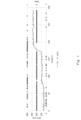
- FIG. 1 shows the result of estimating the state of RTT by GCC using sRTT (smoothed RTT) in a network as an input.
- the horizontal axis indicates the packet numbers of received packets. The received packet with the highest packet number is the most recently received packet.
- the vertical axis on the left indicates sRTT.
- the RTT of the received packet received at time t is RTT_t
- the sRTT of the received packet received at time t-1 is sRTT_(t-1).
- sRTT_t which is the sRTT of the received packet received at time t, is expressed as Equation 1 below.
- the vertical axis on the right side indicates the estimation result of the RTT state. State “1" indicates that the RTT is increasing, State “0” indicates that the RTT is stable, and State “-1" indicates that the RTT is decreasing.
- GCC is able to quickly estimate the state of RTT.
- GCC determines that the RTT is increasing or decreasing, even if the RTT is actually stable. As a result, it can be seen that GCC does not stabilize the estimation accuracy of the RTT state.
- an object of the present disclosure is to provide a network state estimation device, a network state estimation system, and a network state estimation method that are capable of stabilizing the estimation accuracy of the network state.
- a network state estimation method comprises: an RTT acquisition step of acquiring the RTT (Round Trip Time) of each of the first received packet and the second received packet received via the network; a difference calculation step of calculating an RTT difference, which is the difference between the RTT of the first received packet and the RTT of the second received packet; a filtering step of smoothing the RTT difference using a plurality of stages of Kalman filters connected in series; a threshold specifying step of specifying a threshold for the output of the last-stage Kalman filter among the plurality of stages of Kalman filters based on the output of the first-stage Kalman filter among the plurality of stages of Kalman filters; a state estimation step of comparing an output of a final-stage Kalman filter among the plurality of stages of Kalman filters with the identified threshold value, and estimating a state of the network based on the comparison result.
- a network state estimator comprises: an RTT acquisition unit that acquires the RTT (Round Trip Time) of each of the first received packet and the second received packet received via the network; a difference calculation unit that calculates an RTT difference, which is the difference between the RTT of the first received packet and the RTT of the second received packet; a filter unit that smoothes the RTT difference using a plurality of stages of Kalman filters connected in series; a threshold specifying unit that specifies a threshold for the output of the last-stage Kalman filter among the plurality of stages of Kalman filters based on the output of the first-stage Kalman filter among the plurality of stages of Kalman filters; a state estimating unit that compares the output of the Kalman filter at the final stage among the Kalman filters at the plurality of stages with the specified threshold value, and estimates the state of the network based on the comparison result.
- a network state estimation system comprises: an RTT acquisition unit that acquires the RTT (Round Trip Time) of each of the first received packet and the second received packet received via the network; a difference calculation unit that calculates an RTT difference, which is the difference between the RTT of the first received packet and the RTT of the second received packet; a filter unit that smoothes the RTT difference using a plurality of stages of Kalman filters connected in series; a threshold specifying unit that specifies a threshold for the output of the last-stage Kalman filter among the plurality of stages of Kalman filters based on the output of the first-stage Kalman filter among the plurality of stages of Kalman filters; a state estimating unit that compares the output of the Kalman filter at the final stage among the Kalman filters at the plurality of stages with the specified threshold value, and estimates the state of the network based on the comparison result.
- FIG. 1 is a diagram showing a configuration example of a network state estimation device according to Embodiment 1;
- FIG. FIG. 4 is a flow diagram illustrating an example of a schematic operation flow of the network state estimation device according to Embodiment 1;
- 1 is a diagram showing a configuration example of a network state estimation system according to Embodiment 1;
- FIG. 9 is a diagram showing a configuration example of a network state estimation device according to Embodiment 2;
- FIG. 10 is a diagram showing an example of sRTT output from an sRTT acquisition unit according to Embodiment 2;
- FIG. 10 is a diagram showing an example of RTT difference output from a difference calculation unit according to Embodiment 2;
- FIG. 10 is a diagram showing an example of an RTT difference that is output from the first-stage Kalman filter according to Embodiment 2 and that has undergone one-stage smoothing;
- FIG. 10 is a diagram showing an example of an RTT difference that has been smoothed in two stages and is output from a Kalman filter in the final stage according to Embodiment 2;
- FIG. 10 is a diagram showing an example of thresholds output from a threshold specifying unit according to the second embodiment;
- FIG. FIG. 10 is a diagram showing an example of an estimation result of the state of RTT output from a state estimating unit according to Embodiment 2;
- FIG. 4 is a diagram showing an example of a result of estimating the state of RTT in a certain mobile network by GCC;
- FIG. 13 is a diagram showing an example of a result of estimating the state of RTT in the same mobile network as in FIG. 12 by the state estimating unit according to the second embodiment;
- FIG. 10 is a flow diagram illustrating an example of a schematic operation flow of a network state estimation device according to Embodiment 2;
- FIG. 10 is a diagram showing a configuration example of a network state estimation device according to Embodiment 3;
- FIG. 12 is a diagram for explaining an example of a reception interval calculation method by a reception interval calculator according to Embodiment 3;
- FIG. 12 is a flow diagram illustrating an example of a schematic operation flow of a reception interval calculation unit according to Embodiment 3;
- 2 is a block diagram showing a hardware configuration example of a computer that implements the network state estimation device according to Embodiments 1, 2, and 3;
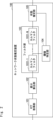
- network state estimation apparatus 100 includes RTT acquisition section 101, difference calculation section 102, filter section 103, threshold identification section 104, and state estimation section 105. , is equipped with
- the network state estimation device 100 may be a device that itself transmits and receives packets. In this case, the network state estimation device 100 estimates the state of the network that the network state estimation device 100 uses for packet transmission/reception. Alternatively, the network state estimation device 100 may be a device provided separately from other devices that transmit and receive packets. In this case, the network state estimation device 100 estimates the state of the network used by other devices for packet transmission/reception.
- the RTT acquisition unit 101 acquires the RTT of each of the first received packet and the second received packet received via the network. It is assumed that the first received packet and the second received packet are received in this order.
- the RTT of the first received packet is the network state estimating device 100 or another device, after the network state estimating device 100 or another device transmits a transmission packet, the first received packet, which is a response packet to the transmission packet, is the network state estimating device 100 or another device. is the time until the Note that the RTT may be calculated by an arbitrary component within the network state estimation device 100, or may be received from an external device.
- Difference calculation section 102 calculates an RTT difference, which is the difference (that is, the gradient) between the RTT of the first received packet and the RTT of the second received packet.
- Filter section 103 includes a plurality of stages of Kalman filters 1031-1 to 1031-N (N is an integer equal to or greater than 2) connected in series. Filter section 103 smoothes the RTT difference calculated by difference calculation section 102 using multi-stage Kalman filters 1031-1 to 1031-N.
- a threshold for the output of the final-stage Kalman filter 1031-N among the multiple-stage Kalman filters 1031-1 to 1031-N is specified.
- State estimating section 105 uses the output of final-stage Kalman filter 1031-N among multiple-stage Kalman filters 1031-1 to 1031-N, that is, the result of smoothing the RTT difference in N stages as a threshold value. It compares with the threshold specified by the specifying unit 104, and estimates the state of the network based on the comparison result.
- the network status indicates the communication status in the network, for example, the increase/decrease status of RTT in the network.
- the RTT obtaining unit 101 obtains the RTT of each of the first received packet and the second received packet received via the network (step S11).
- the difference calculator 102 calculates an RTT difference, which is the difference between the RTT of the first received packet and the RTT of the second received packet (step S12).
- the filter unit 103 uses the multi-stage Kalman filters 1031-1 to 1031-N to smooth the RTT difference calculated by the difference calculation unit 102 (step S13).
- the threshold specifying unit 104 specifies a threshold based on the output of the first-stage Kalman filter 1031-1 among the multiple-stage Kalman filters 1031-1 to 1031-N (step S14). Note that step S14 may be performed when the smoothing by the first-stage Kalman filter 1031-1 is completed in the middle of step S13 without waiting for the completion of step S13.
- state estimating section 105 compares the output of final-stage Kalman filter 1031-N among multi-stage Kalman filters 1031-1 to 1031-N with the threshold value specified by threshold value specifying section 104, and based on the comparison result, to estimate the state of the network (step S15).
- network state estimation apparatus 100 acquires the RTT of each of the first received packet and the second received packet received via the network, and obtains the RTT of the first received packet and the RTT of the second received packet. Then, network state estimation apparatus 100 smoothes the RTT difference using multi-stage Kalman filters 1031-1 to 1031-N. Then, network state estimation apparatus 100 identifies a threshold based on the output of first-stage Kalman filter 1031-1, compares the output of final-stage Kalman filter 1031-N with the threshold, and determines the network state based on the comparison result.
- the RTT obtaining unit 101 may further obtain sRTT from the RTTs of the first received packet and the second received packet using Equation 1 above.
- the latter component of the RTT acquisition unit 101 may estimate the network state using the sRTT of each of the first received packet and the second received packet.
- the threshold identifying unit 104 determines the threshold for the second received packet. Calculate a candidate threshold that is a candidate for the threshold at the time of reception, calculate the maximum value of the calculated candidate threshold and a predetermined lower limit, and use the calculated maximum value at the time of reception of the second received packet You may specify as a threshold value.
- the lower limit may be set based on the scheduling characteristics of the network.
- the scheduling characteristic of the network is, for example, the interval of uplink slots assigned to the uplink when there is a device that communicates in TDD (Time Division Duplex) in the network.
- TDD Time Division Duplex
- the source of a received packet received by network state estimation device 100 or another device is a base station that communicates in the TDD scheme.
- the interval between uplink slots is generally longer than the interval between downlink slots allocated to the downlink. Therefore, even if a terminal such as a UE (User Equipment) connected to a base station generates a packet to be transmitted to the base station, it cannot immediately transmit the packet and is forced to wait until the next uplink slot. can occur.
- UE User Equipment
- the RTT fluctuates in a constant cycle depending on the interval of uplink slots. Therefore, when the transmission source of the received packet is the above-described base station, the lower limit value is set based on the upstream slot interval so as not to fall below the RTT variation.
- the state estimation unit 105 may estimate the increase/decrease of RTT in the network as the state of the network. Further, network state estimation apparatus 100, based on the transmission interval of transmission packets for the first received packet and the second received packet, the RTT of the first received packet, and the RTT of the second received packet, A reception interval calculator that calculates a reception interval between the first received packet and the second received packet may be further provided.
- the RTT acquisition unit 101, the difference calculation unit 102, the filter unit 103, the threshold identification unit 104, and the state estimation unit 105 are not limited to being provided in one device (network state estimation device 100). As shown in FIG. 4, the RTT acquisition unit 101, the difference calculation unit 102, the filter unit 103, the threshold identification unit 104, and the state estimation unit 105 are distributed in different devices or clouds, etc., and the network state is estimated. You may configure the system 100A.
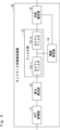
- network state estimation apparatus 10 includes sRTT acquisition unit 11, difference calculation unit 12, filter unit 13, threshold value identification unit 14, and state estimation unit 15. , is equipped with
- the network state estimation device 10 may be a device that itself transmits and receives packets. In this case, the network state estimation device 10 estimates the state of the network that the network state estimation device 10 uses for packet transmission/reception. Alternatively, the network state estimation device 10 may be a device provided separately from other devices that transmit and receive packets. In this case, the network state estimation device 10 estimates the state of the network used by other devices for packet transmission/reception.
- the sRTT acquisition unit 11 acquires the sRTT of each received packet received via the network.
- the sRTT may be calculated by an arbitrary component within the network state estimation device 10, or may be received from an external device.
- the sRTT acquisition unit 11 first uses ping to acquire the RTT of each received packet, and then, from the RTT of each received packet, formula 1 described above is may be used to calculate and obtain the sRTT of each received packet.
- the method of acquiring sRTT is not limited to this.
- the RTT of a received packet is the time from when the network state estimation device 10 or another device transmits a transmission packet until the reception packet, which is a response packet to the transmission packet, is received by the network state estimation device 10 or another device. It's time.
- FIG. 6 shows an example of sRTT output from the sRTT acquisition unit 11. As shown in FIG. In FIG. 6, the horizontal axis indicates the packet number of the received packet, and the vertical axis indicates the sRTT.
- the difference calculator 12 calculates the RTT difference, which is the difference (that is, the gradient) between the sRTT of the received packet and the sRTT of the received packet received before the received packet.
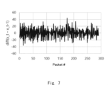
- FIG. 7 shows an example of the RTT difference output from the difference calculation unit 12.
- the horizontal axis indicates the packet number of the received packet
- the vertical axis indicates the RTT difference.
- x_t indicates the sRTT of the received packet received at time t
- x_t-1 indicates the sRTT of the received packet received at time t-1.
- the filter unit 13 includes two-stage Kalman filters 131-1 and 131-2 connected in series. However, the number of stages of the Kalman filter included in the filter unit 13 is not limited to two, and may be three or more.
- the filter unit 13 smoothes the RTT difference calculated by the difference calculation unit 12 using two-stage Kalman filters 131-1 and 131-2.
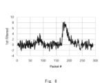
- FIG. 8 shows an example of the RTT difference output from the first-stage Kalman filter 131-1 and subjected to one-stage smoothing.
- FIG. 9 shows an example of the RTT difference that has been smoothed in two stages, which is output from the final-stage Kalman filter 131-2. 8 and 9, the horizontal axis indicates the packet number of the received packet, and the vertical axis indicates the smoothed RTT difference.
- the threshold specifying unit 14 specifies a threshold based on the output of the first-stage Kalman filter 131-1 of the two-stage Kalman filters 131-1 and 131-2, ie, the RTT difference smoothed by one stage.
- FIG. 10 shows an example of thresholds output from the threshold specifying unit 14.
- the horizontal axis indicates the packet number of the received packet
- the vertical axis indicates the threshold.
- the threshold is dynamically set for each received packet upon receipt of that received packet.
- the thresholds are set on the plus side and the minus side, respectively, and the plus side threshold and the minus side threshold are symmetrical values across the axis of the threshold "0".
- the state estimating unit 15 uses the threshold specifying unit 14 to specify the output of the final-stage Kalman filter 131-2 among the two-stage Kalman filters 131-1 to 131-2, that is, the RTT difference smoothed in two stages. Compare with the specified threshold. Then, based on the comparison result, the state estimation unit 15 estimates the RTT state (increase/decrease state) in the network as the network state. Here, the state estimation unit 15 estimates whether the state of RTT is increasing, stable, or decreasing.
- the state estimating unit 15 determines that if the output of the last-stage Kalman filter 131-2 is greater than the plus-side threshold, If it is less than the negative threshold, it is estimated to be decreasing, and if it is within the range between the positive and negative thresholds, it is estimated to be stable.
- FIG. 11 shows an example of the RTT state estimation result output from the state estimating unit 15 .
- the horizontal axis indicates the packet number of the received packet
- the vertical axis indicates the estimation result of the RTT state. State “1" indicates that the RTT is increasing, and State “0” indicates that the RTT is stable. Also, although not shown, State "-1" indicates that the RTT is decreasing.
- a method of specifying a threshold by the threshold specifying unit 14 will be described in detail below.
- the threshold specification method by GCC described in Non-Patent Document 1 will be described.
- GCC In GCC, let ⁇ (t i ) be the threshold when receiving the i-th received packet, let ⁇ (t i-1 ) be the threshold when receiving the i-1-th received packet, and let ⁇ (t i-1 ) be the threshold when receiving the i-th received packet.
- m(t i ) be the output of the first-stage Kalman filter. Since only one stage of Kalman filter is provided in GCC, the output of the one stage Kalman filter becomes the output of the first stage Kalman filter.
- GCC specifies ⁇ (t i ) as in Equation 2 below.
- ⁇ T t i ⁇ t i ⁇ 1
- k ⁇ (t i ) is a coefficient at the time of reception of the i-th received packet, which varies with time.
- the threshold specifying unit 14 sets a lower limit according to the schedule characteristics of the network, and specifies the threshold so as not to fall below the lower limit.
- a scheduling characteristic of a network is, for example, the interval of upstream slots when there are devices communicating in TDD in the network.
- the source of a received packet received by the network state estimation device 10 or another device is a base station that communicates using the TDD method.
- the RTT fluctuates in a constant cycle depending on the uplink slot interval.
- the threshold specifying unit 14 sets the lower limit value based on the interval of the uplink slots so as not to fall below the variation of the RTT. Specifically, assuming that the interval between upstream slots is T tdd , the threshold specifying unit 14 sets the lower limit value ⁇ tdd (t i ) to T tdd .
- the threshold identification unit 14 identifies ⁇ (t i ) as in Equation 3 below.
- ⁇ (t i ), ⁇ (t i ⁇ 1 ), and m(t i ) are the same as in Equation 2.
- the output of the Kalman filter 131-1 is the output of the first-stage Kalman filter, that is, m(t i ).
- k ⁇ is a fixed coefficient that does not fluctuate over time.
- the computational cost and computation time are reduced compared to GCC using a time-varying ⁇ T ⁇ k ⁇ (t i ). can be achieved.
- the threshold specifying unit 14 first calculates a candidate threshold that is a candidate threshold in the same manner as in Equation 2 except that k ⁇ is used, and the calculated candidate threshold and the above-described candidate threshold Calculate the maximum value between the lower limit and the lower limit. Then, the threshold specifying unit 14 specifies the calculated maximum value as ⁇ (t i ).
- FIG. 12 shows an example of the result of estimating the RTT state in a certain mobile network by GCC.
- an intentional delay is generated during communication.
- FIG. 13 shows an example of the result of estimating the RTT state in the same mobile network as in FIG. 12 by the state estimating unit 15 according to the second embodiment. 12 and 13, the horizontal axis indicates the reception time of the received packet, and the left vertical axis and right vertical axis are the same as in FIG.
- the RTT state (increase, decrease or stability) is accurately estimated.
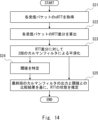
- the sRTT acquisition unit 11 acquires the sRTT of each received packet received via the network (step S21).
- the difference calculator 12 calculates the RTT difference, which is the difference between the sRTT of the received packet and the sRTT of the received packet received before the received packet (step S22).
- the filter unit 13 uses the two-stage Kalman filters 131-1 and 131-2 to smooth the RTT difference calculated by the difference calculation unit 12 (step S23).
- step S24 identifies a threshold based on the output of the first-stage Kalman filter 131-1 of the two-stage Kalman filters 131-1 and 131-2 (step S24). Note that step S24 may be performed when the smoothing by the first-stage Kalman filter 131-1 is completed in the middle of step S23 without waiting for the completion of step S23.
- the state estimating unit 15 compares the output of the last-stage Kalman filter 131-2 among the two-stage Kalman filters 131-1 to 131-2 with the threshold specified by the threshold specifying unit 14, and based on the comparison result, to estimate the state of RTT in the network (step S25).
- the network state estimation device 10 acquires the sRTT of each received packet received via the network and calculates the RTT difference for each received packet. Then, network state estimation apparatus 10 smoothes the RTT difference using two-stage Kalman filters 131-1 and 131-2. Then, the network state estimation device 10 identifies a threshold value based on the output of the first-stage Kalman filter 131-1, compares the output of the final-stage Kalman filter 131-2 with the threshold value, and determines the RTT in the network based on the comparison result. Estimate the state of In this way, by smoothing the RTT difference using the two-stage Kalman filters 131-1 and 131-2, it is possible to stabilize the estimation accuracy of the RTT state in the network. Also, as a result, it becomes possible to appropriately perform remote monitoring or remote control using the stabilized estimation result of the RTT state in the network.
- the network state estimation device 10 sets the lower limit of the threshold based on the schedule characteristics of the network, and identifies the maximum value of the candidate threshold and the lower limit as the threshold. Thereby, the threshold can be specified so as not to fall below the lower limit. Specifying such a threshold can also contribute to stabilization of the estimation accuracy of the RTT state.
- the network state estimation device 10A according to the third embodiment has a reception interval calculation unit 16, compared to the network state estimation device 10 according to the second embodiment described above. Points are different.
- the reception interval calculator 16 calculates the reception interval of received packets. A method of calculating the reception interval by the reception interval calculator 16 will be described in detail below with reference to FIG.
- ⁇ be the transmission interval of transmission packets transmitted by the network state estimation device 10 or another device
- si be the transmission time at which the i-th transmission packet is transmitted
- Equation 4 which is the RTT of the i-th received packet.
- the reception interval d i,i+1 between the i-th received packet and the i+1-th received packet is calculated as in Equation 5 below.
- Equation 5 for the reception interval is modified using Equation 4 for RTT, Equation 6 below is obtained.
- the reception interval d i,i+1 is calculated based on the transmission interval ⁇ of the transmission packet, u i which is the RTT of the i-th received packet, and u i+1 which is the RTT of the i+1-th received packet. can be done.
- the reception interval calculator 16 calculates the reception interval between the i-th received packet and the i+1-th received packet based on the transmission interval of the transmitted packet, the RTT of the i-th received packet, and the RTT of the i+1-th received packet. Calculate
- the transmission interval of transmission packets is a predetermined set value. Therefore, the reception interval calculator 16 holds in advance the transmission interval of transmission packets. Also, the reception interval calculation unit 16 acquires the RTTs of the i-th and i+1-th reception packets from the sRTT acquisition unit 11 . However, it is not limited to this, and the reception interval calculator 16 itself may use ping to acquire the RTTs of the i-th and i+1-th received packets.
- reception interval calculator 16 calculates the reception interval between the i-th received packet and the (i+1)-th received packet.
- the reception interval calculation unit 16 acquires the RTTs of the i-th and i+1-th received packets from the sRTT acquisition unit 11 (step S31). After that, the reception interval calculation unit 16 calculates the difference between the i-th received packet and the i+1-th received packet based on the pre-stored transmission interval of the transmitted packets and the RTTs of the i-th and i+1-th received packets. A reception interval is calculated (step S31).
- the network state estimation device 10A also executes the operation shown in FIG. 14, which is the same as in the second embodiment described above, in addition to executing the operation shown in FIG.
- the network state estimation device 10A may sequentially execute these operations in any order, or may execute these operations substantially simultaneously in parallel.
- the network state estimation device 10A uses the i-th received packet and the i+1 Calculate the reception interval from the second received packet. This makes it possible to calculate the reception interval of received packets. Therefore, it is possible to perform remote monitoring or remote control in consideration of not only the RTT state in the network but also the reception interval of received packets. Further, on the application side, generally, the setting value of the base station, such as the uplink slot interval Ttdd , cannot be obtained from the base station. Therefore, by estimating T tdd using the reception interval of received packets, the lower limit value ⁇ tdd of the dynamic threshold is optimized, and it is expected that the network state (RTT state) can be estimated with high accuracy. Other effects are the same as those of the second embodiment described above.
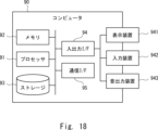
- the computer 90 includes a processor 91, a memory 92, a storage 93, an input/output interface (input/output I/F) 94, a communication interface (communication I/F) 95, and the like.
- the processor 91, the memory 92, the storage 93, the input/output interface 94, and the communication interface 95 are connected by data transmission paths for mutual data transmission/reception.
- the processor 91 is, for example, an arithmetic processing device such as a CPU (Central Processing Unit) or a GPU (Graphics Processing Unit).
- the memory 92 is, for example, RAM (Random Access Memory) or ROM (Read Only Memory).
- the storage 93 is, for example, a storage device such as a HDD (Hard Disk Drive), an SSD (Solid State Drive), or a memory card. Also, the storage 93 may be a memory such as a RAM or a ROM.
- the storage 93 stores programs that implement the functions of the constituent elements of the network state estimation devices 100, 10, and 10A.
- Processor 91 implements the functions of the components included in network state estimation apparatuses 100, 10, and 10A by executing these programs.
- the processor 91 may execute these programs after reading them onto the memory 92 , or may execute them without reading them onto the memory 92 .
- the memory 92 and the storage 93 also play a role of realizing a storage function provided in the network state estimation apparatuses 100, 10, 10A.
- the above-described program is a set of instructions for causing the computer to perform one or more functions in network state estimation apparatuses 100, 10, and 10A described in the above-described embodiments when read into a computer. (or software code).
- the program may be stored in a non-transitory computer-readable medium or tangible storage medium.
- computer readable media or tangible storage media may include RAM, ROM, flash memory, SSD or other memory technology, compact disc (CD)-ROM, digital versatile disk (DVD), Blu-ray ( (registered trademark) discs or other optical disc storage, magnetic cassettes, magnetic tapes, magnetic disk storage or other magnetic storage devices.
- the program may also be transmitted on a transitory computer-readable medium or communication medium.
- transitory computer readable media or communication media include electrical, optical, acoustic, or other forms of propagated signals.
- the input/output interface 94 is connected to a display device 941, an input device 942, a sound output device 943, and the like.
- the display device 941 is a device that displays a screen corresponding to drawing data processed by the processor 91, such as an LCD (Liquid Crystal Display), a CRT (Cathode Ray Tube) display, or a monitor.
- the input device 942 is a device that receives an operator's operational input, such as a keyboard, mouse, and touch sensor.
- the display device 941 and the input device 942 may be integrated and implemented as a touch panel.
- the sound output device 943 is a device, such as a speaker, that outputs sound corresponding to the sound data processed by the processor 91 .
- the communication interface 95 transmits and receives data to and from an external device.
- the communication interface 95 communicates with external devices via wired or wireless communication paths.
- (Appendix 1) an RTT acquisition step of acquiring the RTT (Round Trip Time) of each of the first received packet and the second received packet received via the network; a difference calculation step of calculating an RTT difference, which is the difference between the RTT of the first received packet and the RTT of the second received packet; a filtering step of smoothing the RTT difference using a plurality of stages of Kalman filters connected in series; a threshold specifying step of specifying a threshold for the output of the last-stage Kalman filter among the plurality of stages of Kalman filters based on the output of the first-stage Kalman filter among the plurality of stages of Kalman filters; a state estimation step of comparing the output of the final-stage Kalman filter among the multiple-stage Kalman filters with the specified threshold value, and estimating the state of the network based on the comparison result; Network state estimation method.
- the network state estimation method according to any one of appendices 1 to 3. (Appendix 5) Based on the transmission interval of transmission packets for the first reception packet and the second reception packet, the RTT of the first reception packet, and the RTT of the second reception packet, the first reception further comprising a receiving interval calculation step of calculating a receiving interval between the packet and the second received packet; 5.
- the network state estimation method according to any one of appendices 1 to 4.
- an RTT acquisition unit that acquires the RTT (Round Trip Time) of each of the first received packet and the second received packet received via the network
- a difference calculation unit that calculates an RTT difference, which is the difference between the RTT of the first received packet and the RTT of the second received packet
- a filter unit that smoothes the RTT difference using a plurality of stages of Kalman filters connected in series
- a threshold specifying unit that specifies a threshold for the output of the last-stage Kalman filter among the plurality of stages of Kalman filters based on the output of the first-stage Kalman filter among the plurality of stages of Kalman filters
- a state estimating unit that compares the output of the last-stage Kalman filter among the plurality of stages of Kalman filters with the specified threshold value, and estimates the state of the network based on the comparison result
- Network state estimator
- the threshold specifying unit Based on the threshold when the first received packet is received and the output of the first-stage Kalman filter that smoothes the RTT difference, the threshold when the second received packet is received Calculate a candidate threshold that is a candidate, calculating the maximum value of the calculated candidate threshold and a predetermined lower limit; Identifying the calculated maximum value as the threshold when the second received packet is received;
- the network state estimation device according to appendix 6.
- the lower limit is set based on scheduling characteristics of the network;
- the network state estimation device according to appendix 7. (Appendix 9)
- the state estimation unit estimates the state of increase or decrease of the RTT in the network as the state of the network, 9.
- an RTT acquisition unit that acquires the RTT (Round Trip Time) of each of the first received packet and the second received packet received via the network
- a difference calculation unit that calculates an RTT difference, which is the difference between the RTT of the first received packet and the RTT of the second received packet
- a filter unit that smoothes the RTT difference using a plurality of stages of Kalman filters connected in series
- a threshold specifying unit that specifies a threshold for the output of the last-stage Kalman filter among the plurality of stages of Kalman filters based on the output of the first-stage Kalman filter among the plurality of stages of Kalman filters
- a state estimating unit that compares the output of the last-stage Kalman filter among the plurality of stages of Kalman filters with the specified threshold value, and estimates the state of the network based on the comparison result;
- Network state estimation system Network state estimation system.
- the threshold specifying unit Based on the threshold when the first received packet is received and the output of the first-stage Kalman filter that smoothes the RTT difference, the threshold when the second received packet is received Calculate a candidate threshold that is a candidate, calculating the maximum value of the calculated candidate threshold and a predetermined lower limit; Identifying the calculated maximum value as the threshold when the second received packet is received; 12.
- the network state estimation system according to Supplementary Note 11. (Appendix 13) the lower limit is set based on the scheduling characteristics of the network; 13.
- the state estimation unit estimates the state of increase or decrease of the RTT in the network as the state of the network, 14.
- the network state estimation system according to any one of appendices 11 to 13. (Appendix 15) Based on the transmission interval of transmission packets for the first reception packet and the second reception packet, the RTT of the first reception packet, and the RTT of the second reception packet, the first reception further comprising a reception interval calculator that calculates a reception interval between the packet and the second received packet; 15. The network state estimation system according to any one of appendices 11 to 14.
- 100 network state estimation device 101 RTT acquisition unit 102 difference calculation unit 103 filter unit 1031-1 to 1031-N Kalman filter 104 threshold identification unit 105 state estimation unit 100A network state estimation system 10, 10A network state estimation device 11 sRTT acquisition unit 12 difference Calculation unit 13 filter unit 131-1 to 131-2 Kalman filter 14 threshold identification unit 15 state estimation unit 16 reception interval calculation unit 90 computer 91 processor 92 memory 93 storage 94 input/output interface 941 display device 942 input device 943 sound output device 95 communication interface
Landscapes
- Engineering & Computer Science (AREA)
- Computer Networks & Wireless Communication (AREA)
- Signal Processing (AREA)
- Environmental & Geological Engineering (AREA)
- Data Exchanges In Wide-Area Networks (AREA)
Abstract
本開示に係るネットワーク状態推定装置(100)は、ネットワークを介して受信した第1の受信パケット及び第2の受信パケットの各々のRTTを取得するRTT取得部(101)と、第1の受信パケットのRTTと第2の受信パケットのRTTとの差分であるRTT差分を算出する差分算出部(102)と、互いに直列に接続された複数段のカルマンフィルタ(1031-1~1031-N)を用いて、RTT差分に対してカルマンフィルタリングを行うフィルタ部(103)と、初段のカルマンフィルタ(1031-1)の出力に基づいて、最終段のカルマンフィルタ(1031-N)の出力に対する閾値を特定する閾値特定部(104)と、最終段のカルマンフィルタ(1031-N)の出力を、特定された閾値と比較し、該比較結果に基づいて、ネットワークの状態を推定する状態推定部(105)と、を備える。
Description
本開示は、ネットワーク状態推定装置、ネットワーク状態推定システム、及びネットワーク状態推定方法に関する。
近年、ロボット、工作機械、カメラ等の対象物を、遠隔監視又は遠隔制御することの需要が高まっている。遠隔監視又は遠隔制御では、操作側と対象物との間で高頻度に通信を行う、という特徴がある。そのため、遠隔監視又は遠隔制御を適切に行うためには、通信に用いるネットワークの状態を、リアルタイムにかつロバストに推定する必要がある。
そのため、最近は、ネットワークの状態をリアルタイムにかつロバストに推定する技術が提案されている。その一例として、非特許文献1に開示されたGCC(Google Congestion Control)と呼ばれる技術が挙げられる。
非特許文献1に開示されたGCCは、ネットワークにおけるRTT(Round-Trip-Time)を入力とし、ボトルネックリンクのキューの状態(増加、減少、又は安定)を推定する。以降では、「ボトルネックリンクのキューの状態」を単に「RTTの状態」と呼ぶ。このとき、RTTの変動が激しいために、GCCは、カルマンフィルタを用いて、平滑化を行う。また、GCCは、閾値を用いて、RTTの状態が、増加、減少、又は安定のいずれであるかを推定する。
Gaetano Carlucci等、"Analysis and Design of the Google Congestion Control for Web Real-time Communication (WebRTC)"、Proceedings of the 7th International Conference on Multimedia Systems、2016年5月、Article No. 13、Pages 1-12
しかし、非特許文献1に開示されたGCCは、RTTの状態を高速に推定することはできるものの、推定精度が安定化しないという課題がある。
以下、上述した課題について図1を参照して説明する。
図1は、ネットワークにおけるsRTT(smoothed RTT)を入力とし、GCCによりRTTの状態を推定した結果を示している。
図1において、横軸は受信パケットのパケット番号を示している。パケット番号が最も大きい受信パケットが、最も直近に受信されたパケットとなる。
図1は、ネットワークにおけるsRTT(smoothed RTT)を入力とし、GCCによりRTTの状態を推定した結果を示している。
図1において、横軸は受信パケットのパケット番号を示している。パケット番号が最も大きい受信パケットが、最も直近に受信されたパケットとなる。
また、図1において、左側の縦軸はsRTTを示している。ここで、時刻tで受信した受信パケットのRTTをRTT_t、時刻t-1で受信した受信パケットのsRTTをsRTT_(t-1)とする。すると、時刻tで受信した受信パケットのsRTTであるsRTT_tは、以下の数式1のように表される。

また、図1において、右側の縦軸はRTTの状態の推定結果を示している。State「1」はRTTが増加していることを示し、State「0」はRTTが安定していることを示し、State「-1」はRTTが減少していることを示している。
図1に示されるように、GCCは、RTTの状態を高速に推定することはできている。
しかし、GCCは、実際にはRTTが安定していても、RTTの状態を増加又は減少と判定している箇所が多々ある。その結果、GCCは、RTTの状態の推定精度が安定化しないことがわかる。
しかし、GCCは、実際にはRTTが安定していても、RTTの状態を増加又は減少と判定している箇所が多々ある。その結果、GCCは、RTTの状態の推定精度が安定化しないことがわかる。
そこで本開示の目的は、上述した課題を鑑み、ネットワークの状態の推定精度の安定化を図ることが可能なネットワーク状態推定装置、ネットワーク状態推定システム、及びネットワーク状態推定方法を提供することにある。
一態様によるネットワーク状態推定方法は、
ネットワークを介して受信した第1の受信パケット及び第2の受信パケットの各々のRTT(Round Trip Time)を取得するRTT取得ステップと、
前記第1の受信パケットのRTTと前記第2の受信パケットのRTTとの差分であるRTT差分を算出する差分算出ステップと、
互いに直列に接続された複数段のカルマンフィルタを用いて、前記RTT差分に対して平滑化を行うフィルタリングステップと、
前記複数段のカルマンフィルタのうち初段のカルマンフィルタの出力に基づいて、前記複数段のカルマンフィルタのうち最終段のカルマンフィルタの出力に対する閾値を特定する閾値特定ステップと、
前記複数段のカルマンフィルタのうち最終段のカルマンフィルタの出力を、特定された前記閾値と比較し、該比較結果に基づいて、前記ネットワークの状態を推定する状態推定ステップと、を含む。
一態様によるネットワーク状態推定装置は、
ネットワークを介して受信した第1の受信パケット及び第2の受信パケットの各々のRTT(Round Trip Time)を取得するRTT取得部と、
前記第1の受信パケットのRTTと前記第2の受信パケットのRTTとの差分であるRTT差分を算出する差分算出部と、
互いに直列に接続された複数段のカルマンフィルタを用いて、前記RTT差分に対して平滑化を行うフィルタ部と、
前記複数段のカルマンフィルタのうち初段のカルマンフィルタの出力に基づいて、前記複数段のカルマンフィルタのうち最終段のカルマンフィルタの出力に対する閾値を特定する閾値特定部と、
前記複数段のカルマンフィルタのうち最終段のカルマンフィルタの出力を、特定された前記閾値と比較し、該比較結果に基づいて、前記ネットワークの状態を推定する状態推定部と、を備える。
一態様によるネットワーク状態推定システムは、
ネットワークを介して受信した第1の受信パケット及び第2の受信パケットの各々のRTT(Round Trip Time)を取得するRTT取得部と、
前記第1の受信パケットのRTTと前記第2の受信パケットのRTTとの差分であるRTT差分を算出する差分算出部と、
互いに直列に接続された複数段のカルマンフィルタを用いて、前記RTT差分に対して平滑化を行うフィルタ部と、
前記複数段のカルマンフィルタのうち初段のカルマンフィルタの出力に基づいて、前記複数段のカルマンフィルタのうち最終段のカルマンフィルタの出力に対する閾値を特定する閾値特定部と、
前記複数段のカルマンフィルタのうち最終段のカルマンフィルタの出力を、特定された前記閾値と比較し、該比較結果に基づいて、前記ネットワークの状態を推定する状態推定部と、を備える。
上述の態様によれば、ネットワークの状態の推定精度の安定化を図ることが可能なネットワーク状態推定装置、ネットワーク状態推定システム、及びネットワーク状態推定方法を提供できるという効果が得られる。
以下、図面を参照して本開示の実施の形態について説明する。なお、以下の記載及び図面は、説明の明確化のため、適宜、省略及び簡略化がなされている。また、以下の各図面において、同一の要素には同一の符号が付されており、必要に応じて重複説明は省略されている。また、以下で示す具体的な数値などは、本開示の理解を容易とするための例示にすぎず、これに限定されるものではない。
<実施の形態1>
まず、図2を参照して、本実施の形態1に係るネットワーク状態推定装置100の構成例について説明する。
図2に示されるように、本実施の形態1に係るネットワーク状態推定装置100は、RTT取得部101と、差分算出部102と、フィルタ部103と、閾値特定部104と、状態推定部105と、を備えている。
まず、図2を参照して、本実施の形態1に係るネットワーク状態推定装置100の構成例について説明する。
図2に示されるように、本実施の形態1に係るネットワーク状態推定装置100は、RTT取得部101と、差分算出部102と、フィルタ部103と、閾値特定部104と、状態推定部105と、を備えている。
ネットワーク状態推定装置100は、自身がパケットの送受信を行う装置であっても良い。この場合、ネットワーク状態推定装置100は、ネットワーク状態推定装置100がパケットの送受信に使用するネットワークの状態を推定する。又は、ネットワーク状態推定装置100は、パケットの送受信を行う他装置とは別に設けられた装置であっても良い。この場合、ネットワーク状態推定装置100は、他装置がパケットの送受信に使用するネットワークの状態を推定する。
RTT取得部101は、ネットワークを介して受信した第1の受信パケット及び第2の受信パケットの各々のRTTを取得する。なお、第1の受信パケット及び第2の受信パケットは、この順で受信されるものとする。例えば、第1の受信パケットのRTTは、ネットワーク状態推定装置100又は他装置が送信パケットを送信してから、その送信パケットに対する応答パケットである第1の受信パケットがネットワーク状態推定装置100又は他装置に受信されるまでの時間である。なお、RTTは、ネットワーク状態推定装置100内の任意の構成要素が算出しても良いし、外部の機器から受信しても良い。
差分算出部102は、第1の受信パケットのRTTと第2の受信パケットのRTTとの差分(すなわち、勾配)であるRTT差分を算出する。
フィルタ部103は、互いに直列に接続された複数段のカルマンフィルタ1031-1~1031-N(Nは2以上の整数)を備えている。フィルタ部103は、複数段のカルマンフィルタ1031-1~1031-Nを用いて、差分算出部102により算出されたRTT差分に対して平滑化を行う。
フィルタ部103は、互いに直列に接続された複数段のカルマンフィルタ1031-1~1031-N(Nは2以上の整数)を備えている。フィルタ部103は、複数段のカルマンフィルタ1031-1~1031-Nを用いて、差分算出部102により算出されたRTT差分に対して平滑化を行う。
閾値特定部104は、複数段のカルマンフィルタ1031-1~1031-Nのうち初段のカルマンフィルタ1031-1の出力、すなわち、上述したRTT差分に対して1段の平滑化を行った結果に基づいて、複数段のカルマンフィルタ1031-1~1031-Nのうち最終段のカルマンフィルタ1031-Nの出力に対する閾値を特定する。
状態推定部105は、複数段のカルマンフィルタ1031-1~1031-Nのうち最終段のカルマンフィルタ1031-Nの出力、すなわち、上述したRTT差分に対してN段の平滑化を行った結果を、閾値特定部104により特定された閾値と比較し、その比較結果に基づいて、ネットワークの状態を推定する。ネットワークの状態は、ネットワークにおける通信状況を示し、例えば、ネットワークにおけるRTTの増減の状況を示す。
続いて、図3を参照して、本実施の形態1に係るネットワーク状態推定装置100の概略的な動作フローの例について説明する。
図3に示されるように、まず、RTT取得部101は、ネットワークを介して受信した第1の受信パケット及び第2の受信パケットの各々のRTTを取得する(ステップS11)。
図3に示されるように、まず、RTT取得部101は、ネットワークを介して受信した第1の受信パケット及び第2の受信パケットの各々のRTTを取得する(ステップS11)。
次に、差分算出部102は、第1の受信パケットのRTTと第2の受信パケットのRTTとの差分であるRTT差分を算出する(ステップS12)。
次に、フィルタ部103は、複数段のカルマンフィルタ1031-1~1031-Nを用いて、差分算出部102により算出されたRTT差分に対して平滑化を行う(ステップS13)。
次に、フィルタ部103は、複数段のカルマンフィルタ1031-1~1031-Nを用いて、差分算出部102により算出されたRTT差分に対して平滑化を行う(ステップS13)。
次に、閾値特定部104は、複数段のカルマンフィルタ1031-1~1031-Nのうち初段のカルマンフィルタ1031-1の出力に基づいて、閾値を特定する(ステップS14)。なお、ステップS14は、ステップS13の完了を待たずに、ステップS13の途中で初段のカルマンフィルタ1031-1による平滑化が完了した時点で行っても良い。
その後、状態推定部105は、複数段のカルマンフィルタ1031-1~1031-Nのうち最終段のカルマンフィルタ1031-Nの出力を、閾値特定部104により特定された閾値と比較し、その比較結果に基づいて、ネットワークの状態を推定する(ステップS15)。
上述したように本実施の形態1によれば、ネットワーク状態推定装置100は、ネットワークを介して受信した第1の受信パケット及び第2の受信パケットの各々のRTTを取得し、第1の受信パケットのRTTと第2の受信パケットのRTTとの差分であるRTT差分を算出する。そして、ネットワーク状態推定装置100は、複数段のカルマンフィルタ1031-1~1031-Nを用いて、RTT差分に対して平滑化を行う。そして、ネットワーク状態推定装置100は、初段のカルマンフィルタ1031-1の出力に基づいて閾値を特定し、最終段のカルマンフィルタ1031-Nの出力を閾値と比較し、その比較結果に基づいて、ネットワークの状態を推定する。このように、複数段のカルマンフィルタ1031-1~1031-Nを用いて、RTT差分に対して平滑化を行うことで、ネットワークの状態の推定精度の安定化を図ることが可能となる。また、その結果、ネットワークの状態の安定化した推定結果を用いて、遠隔監視又は遠隔制御を適切に行うことが可能になる。
なお、RTT取得部101は、第1の受信パケット及び第2の受信パケットの各々のRTTから、上述した数式1を用いて、sRTTをさらに取得しても良い。この場合、RTT取得部101の後段の構成要素は、第1の受信パケット及び第2の受信パケットの各々のsRTTを用いて、ネットワークの状態を推定しても良い。
また、閾値特定部104は、第1の受信パケットの受信時の閾値と、RTT差分に対して平滑化を行った初段のカルマンフィルタ1031-1の出力と、に基づいて、第2の受信パケットの受信時の閾値の候補である候補閾値を算出し、算出された候補閾値及び予め決められた下限値のうちの最大値を算出し、算出された最大値を第2の受信パケットの受信時の閾値として特定しても良い。
また、下限値は、ネットワークのスケジューリング特性に基づいて設定されても良い。ネットワークのスケジュール特性は、例えば、ネットワークにおいて、TDD(Time Division Duplex)で通信する装置が存在する場合には、上りリンクに割り当てられた上りスロットの間隔である。例えば、ネットワーク状態推定装置100又は他装置で受信された受信パケットの送信元が、TDD方式で通信する基地局であると仮定する。この場合、上りスロットの間隔は、一般的に、下りリンクに割り当てられた下りスロットの間隔よりも長くなる。そのため、基地局に接続されたUE(User Equipment)等の端末は、基地局に送信すべきパケットが発生したとしても、そのパケットを即座に送信できず、次の上りスロットまで待たされるという事象が発生し得る。そのため、RTTは、上りスロットの間隔に依存して、一定周期で変動する。そのため、受信パケットの送信元が上述した基地局である場合は、下限値は、RTTの変動分を下回らないように、上りスロットの間隔に基づいて設定される。
また、状態推定部105は、ネットワークの状態として、ネットワークにおけるRTTの増減の状況を推定しても良い。
また、ネットワーク状態推定装置100は、第1の受信パケット及び第2の受信パケットに対する送信パケットの送信間隔と、第1の受信パケットのRTTと、第2の受信パケットのRTTと、に基づいて、第1の受信パケットと第2の受信パケットとの受信間隔を算出する受信間隔算出部をさらに備えていても良い。
また、ネットワーク状態推定装置100は、第1の受信パケット及び第2の受信パケットに対する送信パケットの送信間隔と、第1の受信パケットのRTTと、第2の受信パケットのRTTと、に基づいて、第1の受信パケットと第2の受信パケットとの受信間隔を算出する受信間隔算出部をさらに備えていても良い。
また、RTT取得部101、差分算出部102、フィルタ部103、閾値特定部104、及び状態推定部105は、1つの装置(ネットワーク状態推定装置100)に設けられることには、限定されない。図4に示されるように、RTT取得部101、差分算出部102、フィルタ部103、閾値特定部104、及び状態推定部105は、互いに異なる装置又はクラウド等に分散して設けられ、ネットワーク状態推定システム100Aを構成しても良い。
<実施の形態2>
続いて、図5を参照して、本実施の形態2に係るネットワーク状態推定装置10の構成例について説明する。本実施の形態2は、上述した実施の形態1を、より具体化した実施の形態に相当する。
続いて、図5を参照して、本実施の形態2に係るネットワーク状態推定装置10の構成例について説明する。本実施の形態2は、上述した実施の形態1を、より具体化した実施の形態に相当する。
図5に示されるように、本実施の形態2に係るネットワーク状態推定装置10は、sRTT取得部11と、差分算出部12と、フィルタ部13と、閾値特定部14と、状態推定部15と、を備えている。
ネットワーク状態推定装置10は、自身がパケットの送受信を行う装置であっても良い。この場合、ネットワーク状態推定装置10は、ネットワーク状態推定装置10がパケットの送受信に使用するネットワークの状態を推定する。又は、ネットワーク状態推定装置10は、パケットの送受信を行う他装置とは別に設けられた装置であっても良い。この場合、ネットワーク状態推定装置10は、他装置がパケットの送受信に使用するネットワークの状態を推定する。
sRTT取得部11は、ネットワークを介して受信した各受信パケットのsRTTを取得する。なお、sRTTは、ネットワーク状態推定装置10内の任意の構成要素が算出しても良いし、外部の機器から受信しても良い。例えば、sRTT取得部11がsRTTを算出する場合、sRTT取得部11は、まず、pingを利用して、各受信パケットのRTTを取得し、さらに、各受信パケットのRTTから、上述した数式1を用いて、各受信パケットのsRTTを算出し取得しても良い。ただし、sRTTの取得方法は、これに限定されない。なお、受信パケットのRTTは、ネットワーク状態推定装置10又は他装置が送信パケットを送信してから、その送信パケットに対する応答パケットである受信パケットがネットワーク状態推定装置10又は他装置に受信されるまでの時間である。
図6に、sRTT取得部11から出力されるsRTTの例を示す。図6において、横軸は受信パケットのパケット番号を示し、縦軸はsRTTを示している。
図6に、sRTT取得部11から出力されるsRTTの例を示す。図6において、横軸は受信パケットのパケット番号を示し、縦軸はsRTTを示している。
差分算出部12は、各受信パケットについて、その受信パケットのsRTTと、その受信パケットの前に受信した受信パケットのsRTTとの差分(すなわち、勾配)であるRTT差分を算出する。
図7に、差分算出部12から出力されるRTT差分の例を示す。図7において、横軸は受信パケットのパケット番号を示し、縦軸はRTT差分を示している。また、縦軸において、x_tは時刻tで受信した受信パケットのsRTTを示し、x_t-1は時刻t-1で受信した受信パケットのsRTTを示している。
フィルタ部13は、互いに直列に接続された2段のカルマンフィルタ131-1~131-2を備えている。ただし、フィルタ部13が備えるカルマンフィルタの段数は、2段に限定されず、3段以上であっても良い。フィルタ部13は、2段のカルマンフィルタ131-1~131-2を用いて、差分算出部12により算出されたRTT差分に対して平滑化を行う。
図8に、初段のカルマンフィルタ131-1から出力される、1段の平滑化が行われたRTT差分の例を示す。また、図9に、最終段のカルマンフィルタ131-2から出力される、2段の平滑化が行われたRTT差分の例を示す。図8及び図9において、横軸は受信パケットのパケット番号を示し、縦軸は平滑化が行われたRTT差分を示している。
閾値特定部14は、2段のカルマンフィルタ131-1~131-2のうち初段のカルマンフィルタ131-1の出力、すなわち、1段の平滑化が行われたRTT差分に基づいて、閾値を特定する。
図10に、閾値特定部14から出力される閾値の例を示す。図10において、横軸は受信パケットのパケット番号を示し、縦軸は閾値を示している。図10に示されるように、閾値は、受信パケット毎に、その受信パケットの受信時に、動的に設定される。また、閾値は、プラス側及びマイナス側にそれぞれ設定され、プラス側の閾値及びマイナス側の閾値は、閾値「0」の軸線を挟んで、対称な値になっている。
状態推定部15は、2段のカルマンフィルタ131-1~131-2のうち最終段のカルマンフィルタ131-2の出力、すなわち、2段の平滑化が行われたRTT差分を、閾値特定部14により特定された閾値と比較する。そして、状態推定部15は、その比較結果に基づいて、ネットワークの状態として、ネットワークにおけるRTTの状態(増減の状況)を推定する。ここでは、状態推定部15は、RTTの状態が、増加、安定、又は減少のいずれであるかを推定するものとする。例えば、閾値特定部14によりプラス側の閾値及びマイナス側の閾値が特定された場合には、状態推定部15は、最終段のカルマンフィルタ131-2の出力が、プラス側の閾値よりも大きければ、増加と推定し、マイナス側の閾値よりも小さければ、減少と推定し、プラス側の閾値とマイナス側の閾値との間の範囲内にあれば、安定と推定する。
図11に、状態推定部15から出力される、RTTの状態の推定結果の例を示す。図11において、横軸は受信パケットのパケット番号を示し、縦軸はRTTの状態の推定結果を示している。State「1」はRTTが増加していることを示し、State「0」はRTTが安定していることを示している。また、図示していないが、State「-1」はRTTが減少していることを示すものとする。
以下、閾値特定部14による閾値の特定方法について詳細に説明する。ここでは、対比のため、まず、非特許文献1に記載のGCCによる閾値の特定方法について説明する。
GCCにおいて、i番目の受信パケットの受信時の閾値をγ(ti)とし、i-1番目の受信パケットの受信時の閾値をγ(ti-1)とし、i番目の受信パケットについての初段のカルマンフィルタの出力をm(ti)とする。なお、GCCでは、カルマンフィルタが1段のみ設けられているため、その1段のカルマンフィルタの出力が初段のカルマンフィルタの出力となる。GCCでは、γ(ti)を、以下の数式2のように特定する。

ここで、ΔT=ti-ti-1であり、kγ(ti)はi番目の受信パケットの受信時の係数であって、時間に応じて変動する係数である。
ここで、ΔT=ti-ti-1であり、kγ(ti)はi番目の受信パケットの受信時の係数であって、時間に応じて変動する係数である。
続いて、本実施の形態2に係る閾値特定部14による閾値の特定方法について説明する。
閾値特定部14は、ネットワークのスケジュール特性に応じた下限値を設定し、その下限値を下回らないように閾値を特定する。ネットワークのスケジュール特性は、例えば、ネットワークにおいて、TDDで通信する装置が存在する場合には、上りスロットの間隔である。
閾値特定部14は、ネットワークのスケジュール特性に応じた下限値を設定し、その下限値を下回らないように閾値を特定する。ネットワークのスケジュール特性は、例えば、ネットワークにおいて、TDDで通信する装置が存在する場合には、上りスロットの間隔である。
例えば、ネットワーク状態推定装置10又は他装置で受信された受信パケットの送信元が、TDD方式で通信する基地局であると仮定する。この場合、上述したように、RTTは、上りスロットの間隔に依存して、一定周期で変動する。
そのため、受信パケットの送信元が上述した基地局である場合は、閾値特定部14は、RTTの変動分を下回らないように、上りスロットの間隔に基づいて下限値を設定する。具体的には、閾値特定部14は、上りスロットの間隔がTtddであるとすると、下限値γtdd(ti)を、Ttddに設定する。
その上で、閾値特定部14は、以下の数式3のように、γ(ti)を特定する。

ここで、γ(ti)、γ(ti-1)、及びm(ti)は、数式2と同様である。なお、本実施の形態2では、2段のカルマンフィルタ131-1~131-2が設けられているため、カルマンフィルタ131-1の出力が、初段のカルマンフィルタの出力、すなわちm(ti)である。また、kγは、時間変動がない固定の係数である。本実施の形態2では、固定の係数であるkγを使用することにより、時間に応じて変動するΔT×kγ(ti)を使用するGCCと比較して、計算コスト及び計算時間の低減が図れる。
ここで、γ(ti)、γ(ti-1)、及びm(ti)は、数式2と同様である。なお、本実施の形態2では、2段のカルマンフィルタ131-1~131-2が設けられているため、カルマンフィルタ131-1の出力が、初段のカルマンフィルタの出力、すなわちm(ti)である。また、kγは、時間変動がない固定の係数である。本実施の形態2では、固定の係数であるkγを使用することにより、時間に応じて変動するΔT×kγ(ti)を使用するGCCと比較して、計算コスト及び計算時間の低減が図れる。
数式3に示されるように、閾値特定部14は、まず、kγを使用すること以外は数式2と同様の方法で閾値の候補となる候補閾値を算出し、算出された候補閾値と上述した下限値とのうちの最大値を算出する。そして、閾値特定部14は、算出された最大値を、γ(ti)として特定する。
続いて、本実施の形態2に係る状態推定部15によりRTTの状態を推定した結果の例について説明する。ここでは、対比のため、非特許文献1に記載のGCCによりRTTの状態を推定した結果の例についても説明する。
図12は、GCCにより、あるモバイル網におけるRTTの状態を推定した結果の例を示している。図12のモバイル網には、通信途中で意図的な遅延を発生させている。また、図13は、本実施の形態2に係る状態推定部15により、図12と同じモバイル網におけるRTTの状態を推定した結果の例を示している。図12及び図13において、横軸は、受信パケットの受信時刻を示し、左側の縦軸及び右側の縦軸は、図1と同様である。
図12及び図13に示されるように、本実施の形態2では、GCCと比較して、sRTTの変動にロバストになりつつも、意図的に遅延を変更した時刻でも、RTTの状態(増加、減少、又は安定)を正確に推定していることがわかる。
続いて、図14を参照して、本実施の形態2に係るネットワーク状態推定装置10の概略的な動作フローの例について説明する。
図14に示されるように、まず、sRTT取得部11は、ネットワークを介して受信した各受信パケットのsRTTを取得する(ステップS21)。
図14に示されるように、まず、sRTT取得部11は、ネットワークを介して受信した各受信パケットのsRTTを取得する(ステップS21)。
次に、差分算出部12は、各受信パケットについて、その受信パケットのsRTTと、その受信パケットの前に受信した受信パケットのsRTTとの差分であるRTT差分を算出する(ステップS22)。
次に、フィルタ部13は、2段のカルマンフィルタ131-1~131-2を用いて、差分算出部12により算出されたRTT差分に対して平滑化を行う(ステップS23)。
次に、閾値特定部14は、2段のカルマンフィルタ131-1~131-2のうち初段のカルマンフィルタ131-1の出力に基づいて、閾値を特定する(ステップS24)。なお、ステップS24は、ステップS23の完了を待たずに、ステップS23の途中で初段のカルマンフィルタ131-1による平滑化が完了した時点で行っても良い。
その後、状態推定部15は、2段のカルマンフィルタ131-1~131-2のうち最終段のカルマンフィルタ131-2の出力を、閾値特定部14により特定された閾値と比較し、その比較結果に基づいて、ネットワークにおけるRTTの状態を推定する(ステップS25)。
上述したように本実施の形態2によれば、ネットワーク状態推定装置10は、ネットワークを介して受信した各受信パケットのsRTTを取得し、各受信パケットについてRTT差分を算出する。そして、ネットワーク状態推定装置10は、2段のカルマンフィルタ131-1~131-2を用いて、RTT差分に対して平滑化を行う。そして、ネットワーク状態推定装置10は、初段のカルマンフィルタ131-1の出力に基づいて閾値を特定し、最終段のカルマンフィルタ131-2の出力を閾値と比較し、その比較結果に基づいて、ネットワークにおけるRTTの状態を推定する。このように、2段のカルマンフィルタ131-1~131-2を用いて、RTT差分に対して平滑化を行うことで、ネットワークにおけるRTTの状態の推定精度の安定化を図ることが可能となる。また、その結果、ネットワークにおけるRTTの状態の安定化した推定結果を用いて、遠隔監視又は遠隔制御を適切に行うことが可能になる。
また、本実施の形態2によれば、ネットワーク状態推定装置10は、ネットワークのスケジュール特性に基づいて閾値の下限値を設定し、候補閾値及び下限値のうちの最大値を閾値として特定する。これにより、下限値を下回らないように閾値を特定できる。このような閾値の特定によっても、RTTの状態の推定精度の安定化に寄与し得る。
<実施の形態3>
続いて、図15を参照して、本実施の形態3に係るネットワーク状態推定装置10Aの構成例について説明する。
続いて、図15を参照して、本実施の形態3に係るネットワーク状態推定装置10Aの構成例について説明する。
図15に示されるように、本実施の形態3に係るネットワーク状態推定装置10Aは、上述した実施の形態2に係るネットワーク状態推定装置10と比較して、受信間隔算出部16を追加している点が異なる。
受信間隔算出部16は、受信パケットの受信間隔を算出する。
以下、図16を参照して、受信間隔算出部16による受信間隔の算出方法について詳細に説明する。
以下、図16を参照して、受信間隔算出部16による受信間隔の算出方法について詳細に説明する。
ネットワーク状態推定装置10又は他装置が送信する送信パケットの送信間隔をδとし、i番目の送信パケットを送信した送信時刻をsiとし、i番目の送信パケットに対する応答パケットであるi番目の受信パケットをネットワーク状態推定装置10又は他装置が受信した受信時刻をriとする。
このとき、i番目の受信パケットのRTTであるuiは、以下の数式4のように算出される。

また、i番目の受信パケットとi+1番目の受信パケットとの受信間隔di,i+1は、以下の数式5のように算出される。

また、i番目の受信パケットとi+1番目の受信パケットとの受信間隔di,i+1は、以下の数式5のように算出される。
ここで、RTTの数式4を使用して、受信間隔の数式5を変形すると、以下の数式6のようになる。

このように、受信間隔di,i+1は、送信パケットの送信間隔δ、i番目の受信パケットのRTTであるui、及びi+1番目の受信パケットのRTTであるui+1に基づいて、算出することができる。
そこで、受信間隔算出部16は、送信パケットの送信間隔、i番目の受信パケットのRTT、及びi+1番目の受信パケットのRTTに基づいて、i番目の受信パケットとi+1番目の受信パケットとの受信間隔を算出する。
このうち、送信パケットの送信間隔は、予め決められた設定値である。そのため、受信間隔算出部16は、送信パケットの送信間隔については、予め保持しておく。
また、受信間隔算出部16は、i番目及びi+1番目の受信パケットのRTTについては、sRTT取得部11から取得する。ただし、これには限定されず、受信間隔算出部16は、自身でpingを利用して、i番目及びi+1番目の受信パケットのRTTを取得しても良い。
また、受信間隔算出部16は、i番目及びi+1番目の受信パケットのRTTについては、sRTT取得部11から取得する。ただし、これには限定されず、受信間隔算出部16は、自身でpingを利用して、i番目及びi+1番目の受信パケットのRTTを取得しても良い。
続いて、図17を参照して、本実施の形態3に係る受信間隔算出部16の概略的な動作フローの例について説明する。ここでは、受信間隔算出部16は、i番目の受信パケットとi+1番目の受信パケットとの受信間隔を算出するものとする。
図17に示されるように、まず、受信間隔算出部16は、sRTT取得部11から、i番目及びi+1番目の受信パケットのRTTを取得する(ステップS31)。
その後、受信間隔算出部16は、予め保持されている送信パケットの送信間隔と、i番目及びi+1番目の受信パケットのRTTと、に基づいて、i番目の受信パケットとi+1番目の受信パケットとの受信間隔を算出する(ステップS31)。
その後、受信間隔算出部16は、予め保持されている送信パケットの送信間隔と、i番目及びi+1番目の受信パケットのRTTと、に基づいて、i番目の受信パケットとi+1番目の受信パケットとの受信間隔を算出する(ステップS31)。
なお、ネットワーク状態推定装置10Aは、図17に示される動作を実行すること以外に、上述した実施の形態2と同様の図14に示される動作も実行する。ネットワーク状態推定装置10Aは、これらの動作を任意の順番で順次実行しても良いし、これらの動作を略同時に並行に実行しても良い。
上述したように本実施の形態3によれば、ネットワーク状態推定装置10Aは、送信パケットの送信間隔と、i番目及びi+1番目の受信パケットのRTTと、に基づいて、i番目の受信パケットとi+1番目の受信パケットとの受信間隔を算出する。これにより、受信パケットの受信間隔を算出ことが可能となる。そのため、ネットワークにおけるRTTの状態だけでなく、受信パケットの受信間隔も考慮して、遠隔監視又は遠隔制御を行うことが可能になる。また、アプリケーション側では、一般的に、基地局から、上りスロットの間隔Ttddのような基地局の設定値は得られない。そのため、受信パケットの受信間隔を用いてTtddを推定することで動的閾値の下限値γtddが適正化され、高精度にネットワークの状態(RTTの状態)を推定できることが期待される。
その他の効果は、上述した実施の形態2と同様である。
その他の効果は、上述した実施の形態2と同様である。
<実施の形態に係るネットワーク状態推定装置のハードウェア構成>
続いて、図18を参照して、上述した実施の形態1,2,3に係るネットワーク状態推定装置100,10,10Aを実現するコンピュータ90のハードウェア構成例について説明する。
続いて、図18を参照して、上述した実施の形態1,2,3に係るネットワーク状態推定装置100,10,10Aを実現するコンピュータ90のハードウェア構成例について説明する。
図18に示されるように、コンピュータ90は、プロセッサ91、メモリ92、ストレージ93、入出力インタフェース(入出力I/F)94、及び通信インタフェース(通信I/F)95などを備える。プロセッサ91、メモリ92、ストレージ93、入出力インタフェース94、及び通信インタフェース95は、相互にデータを送受信するためのデータ伝送路で接続されている。
プロセッサ91は、例えば、CPU(Central Processing Unit)やGPU(Graphics Processing Unit)などの演算処理装置である。メモリ92は、例えばRAM(Random Access Memory)やROM(Read Only Memory)などのメモリである。ストレージ93は、例えば、HDD(Hard Disk Drive)、SSD(Solid State Drive)、又はメモリカードなどの記憶装置である。また、ストレージ93は、RAMやROMなどのメモリであっても良い。
ストレージ93は、ネットワーク状態推定装置100,10,10Aが備える構成要素の機能を実現するプログラムを記憶している。プロセッサ91は、これら各プログラムを実行することで、ネットワーク状態推定装置100,10,10Aが備える構成要素の機能をそれぞれ実現する。ここで、プロセッサ91は、上記各プログラムを実行する際、これらのプログラムをメモリ92上に読み出してから実行しても良いし、メモリ92上に読み出さずに実行しても良い。また、メモリ92やストレージ93は、ネットワーク状態推定装置100,10,10Aが備える記憶機能を実現する役割も果たす。
また、上述したプログラムは、コンピュータに読み込まれた場合に、上述した実施の形態で説明された、ネットワーク状態推定装置100,10,10Aにおける1又はそれ以上の機能をコンピュータに行わせるための命令群(又はソフトウェアコード)を含む。プログラムは、非一時的なコンピュータ可読媒体又は実体のある記憶媒体に格納されても良い。限定ではなく例として、コンピュータ可読媒体又は実体のある記憶媒体は、RAM、ROM、フラッシュメモリ、SSD又はその他のメモリ技術、compact disc(CD)-ROM、digital versatile disk(DVD)、Blu-ray(登録商標)ディスク又はその他の光ディスクストレージ、磁気カセット、磁気テープ、磁気ディスクストレージ又はその他の磁気ストレージデバイスを含む。プログラムは、一時的なコンピュータ可読媒体又は通信媒体上で送信されても良い。限定ではなく例として、一時的なコンピュータ可読媒体又は通信媒体は、電気的、光学的、音響的、又はその他の形式の伝搬信号を含む。
入出力インタフェース94は、表示装置941、入力装置942、音出力装置943などと接続される。表示装置941は、LCD(Liquid Crystal Display)、CRT(Cathode Ray Tube)ディスプレイ、モニターのような、プロセッサ91により処理された描画データに対応する画面を表示する装置である。入力装置942は、オペレータの操作入力を受け付ける装置であり、例えば、キーボード、マウス、及びタッチセンサなどである。表示装置941及び入力装置942は一体化され、タッチパネルとして実現されていても良い。音出力装置943は、スピーカのような、プロセッサ91により処理された音響データに対応する音を音響出力する装置である。
通信インタフェース95は、外部の装置との間でデータを送受信する。例えば、通信インタフェース95は、有線通信路または無線通信路を介して外部装置と通信する。
以上、実施の形態を参照して本開示を説明したが、本開示は上述した実施の形態に限定されるものではない。本開示の構成や詳細には、本開示のスコープ内で当業者が理解し得る様々な変更をすることができる。
例えば、上述した各実施の形態は組み合わされて用いられても良い。
例えば、上述した各実施の形態は組み合わされて用いられても良い。
また、上述した実施の形態の一部又は全部は、以下の付記のようにも記載されうるが、以下には限られない。
(付記1)
ネットワークを介して受信した第1の受信パケット及び第2の受信パケットの各々のRTT(Round Trip Time)を取得するRTT取得ステップと、
前記第1の受信パケットのRTTと前記第2の受信パケットのRTTとの差分であるRTT差分を算出する差分算出ステップと、
互いに直列に接続された複数段のカルマンフィルタを用いて、前記RTT差分に対して平滑化を行うフィルタリングステップと、
前記複数段のカルマンフィルタのうち初段のカルマンフィルタの出力に基づいて、前記複数段のカルマンフィルタのうち最終段のカルマンフィルタの出力に対する閾値を特定する閾値特定ステップと、
前記複数段のカルマンフィルタのうち最終段のカルマンフィルタの出力を、特定された前記閾値と比較し、該比較結果に基づいて、前記ネットワークの状態を推定する状態推定ステップと、を含む、
ネットワーク状態推定方法。
(付記2)
前記閾値特定ステップでは、
前記第1の受信パケットの受信時の前記閾値と、前記RTT差分に対して平滑化を行った前記初段のカルマンフィルタの出力と、に基づいて、前記第2の受信パケットの受信時の前記閾値の候補である候補閾値を算出し、
算出された前記候補閾値及び予め決められた下限値のうちの最大値を算出し、
算出された前記最大値を、前記第2の受信パケットの受信時の前記閾値として特定する、
付記1に記載のネットワーク状態推定方法。
(付記3)
前記下限値は、前記ネットワークのスケジューリング特性に基づいて設定される、
付記2に記載のネットワーク状態推定方法。
(付記4)
前記状態推定ステップでは、前記ネットワークの状態として、前記ネットワークにおける前記RTTの増減の状況を推定する、
付記1から3のいずれか1項に記載のネットワーク状態推定方法。
(付記5)
前記第1の受信パケット及び前記第2の受信パケットに対する送信パケットの送信間隔と、前記第1の受信パケットのRTTと、前記第2の受信パケットのRTTと、に基づいて、前記第1の受信パケットと前記第2の受信パケットとの受信間隔を算出する受信間隔算出ステップをさらに含む、
付記1から4のいずれか1項に記載のネットワーク状態推定方法。
(付記6)
ネットワークを介して受信した第1の受信パケット及び第2の受信パケットの各々のRTT(Round Trip Time)を取得するRTT取得部と、
前記第1の受信パケットのRTTと前記第2の受信パケットのRTTとの差分であるRTT差分を算出する差分算出部と、
互いに直列に接続された複数段のカルマンフィルタを用いて、前記RTT差分に対して平滑化を行うフィルタ部と、
前記複数段のカルマンフィルタのうち初段のカルマンフィルタの出力に基づいて、前記複数段のカルマンフィルタのうち最終段のカルマンフィルタの出力に対する閾値を特定する閾値特定部と、
前記複数段のカルマンフィルタのうち最終段のカルマンフィルタの出力を、特定された前記閾値と比較し、該比較結果に基づいて、前記ネットワークの状態を推定する状態推定部と、を備える、
ネットワーク状態推定装置。
(付記7)
前記閾値特定部は、
前記第1の受信パケットの受信時の前記閾値と、前記RTT差分に対して平滑化を行った前記初段のカルマンフィルタの出力と、に基づいて、前記第2の受信パケットの受信時の前記閾値の候補である候補閾値を算出し、
算出された前記候補閾値及び予め決められた下限値のうちの最大値を算出し、
算出された前記最大値を、前記第2の受信パケットの受信時の前記閾値として特定する、
付記6に記載のネットワーク状態推定装置。
(付記8)
前記下限値は、前記ネットワークのスケジューリング特性に基づいて設定される、
付記7に記載のネットワーク状態推定装置。
(付記9)
前記状態推定部は、前記ネットワークの状態として、前記ネットワークにおける前記RTTの増減の状況を推定する、
付記6から8のいずれか1項に記載のネットワーク状態推定装置。
(付記10)
前記第1の受信パケット及び前記第2の受信パケットに対する送信パケットの送信間隔と、前記第1の受信パケットのRTTと、前記第2の受信パケットのRTTと、に基づいて、前記第1の受信パケットと前記第2の受信パケットとの受信間隔を算出する受信間隔算出部をさらに備える、
付記6から9のいずれか1項に記載のネットワーク状態推定装置。
(付記11)
ネットワークを介して受信した第1の受信パケット及び第2の受信パケットの各々のRTT(Round Trip Time)を取得するRTT取得部と、
前記第1の受信パケットのRTTと前記第2の受信パケットのRTTとの差分であるRTT差分を算出する差分算出部と、
互いに直列に接続された複数段のカルマンフィルタを用いて、前記RTT差分に対して平滑化を行うフィルタ部と、
前記複数段のカルマンフィルタのうち初段のカルマンフィルタの出力に基づいて、前記複数段のカルマンフィルタのうち最終段のカルマンフィルタの出力に対する閾値を特定する閾値特定部と、
前記複数段のカルマンフィルタのうち最終段のカルマンフィルタの出力を、特定された前記閾値と比較し、該比較結果に基づいて、前記ネットワークの状態を推定する状態推定部と、を備える、
ネットワーク状態推定システム。
(付記12)
前記閾値特定部は、
前記第1の受信パケットの受信時の前記閾値と、前記RTT差分に対して平滑化を行った前記初段のカルマンフィルタの出力と、に基づいて、前記第2の受信パケットの受信時の前記閾値の候補である候補閾値を算出し、
算出された前記候補閾値及び予め決められた下限値のうちの最大値を算出し、
算出された前記最大値を、前記第2の受信パケットの受信時の前記閾値として特定する、
付記11に記載のネットワーク状態推定システム。
(付記13)
前記下限値は、前記ネットワークのスケジューリング特性に基づいて設定される、
付記12に記載のネットワーク状態推定システム。
(付記14)
前記状態推定部は、前記ネットワークの状態として、前記ネットワークにおける前記RTTの増減の状況を推定する、
付記11から13のいずれか1項に記載のネットワーク状態推定システム。
(付記15)
前記第1の受信パケット及び前記第2の受信パケットに対する送信パケットの送信間隔と、前記第1の受信パケットのRTTと、前記第2の受信パケットのRTTと、に基づいて、前記第1の受信パケットと前記第2の受信パケットとの受信間隔を算出する受信間隔算出部をさらに備える、
付記11から14のいずれか1項に記載のネットワーク状態推定システム。
100 ネットワーク状態推定装置
101 RTT取得部
102 差分算出部
103 フィルタ部
1031-1~1031-N カルマンフィルタ
104 閾値特定部
105 状態推定部
100A ネットワーク状態推定システム
10,10A ネットワーク状態推定装置
11 sRTT取得部
12 差分算出部
13 フィルタ部
131-1~131-2 カルマンフィルタ
14 閾値特定部
15 状態推定部
16 受信間隔算出部
90 コンピュータ
91 プロセッサ
92 メモリ
93 ストレージ
94 入出力インタフェース
941 表示装置
942 入力装置
943 音出力装置
95 通信インタフェース
101 RTT取得部
102 差分算出部
103 フィルタ部
1031-1~1031-N カルマンフィルタ
104 閾値特定部
105 状態推定部
100A ネットワーク状態推定システム
10,10A ネットワーク状態推定装置
11 sRTT取得部
12 差分算出部
13 フィルタ部
131-1~131-2 カルマンフィルタ
14 閾値特定部
15 状態推定部
16 受信間隔算出部
90 コンピュータ
91 プロセッサ
92 メモリ
93 ストレージ
94 入出力インタフェース
941 表示装置
942 入力装置
943 音出力装置
95 通信インタフェース
Claims (15)
- ネットワークを介して受信した第1の受信パケット及び第2の受信パケットの各々のRTT(Round Trip Time)を取得するRTT取得ステップと、
前記第1の受信パケットのRTTと前記第2の受信パケットのRTTとの差分であるRTT差分を算出する差分算出ステップと、
互いに直列に接続された複数段のカルマンフィルタを用いて、前記RTT差分に対して平滑化を行うフィルタリングステップと、
前記複数段のカルマンフィルタのうち初段のカルマンフィルタの出力に基づいて、前記複数段のカルマンフィルタのうち最終段のカルマンフィルタの出力に対する閾値を特定する閾値特定ステップと、
前記複数段のカルマンフィルタのうち最終段のカルマンフィルタの出力を、特定された前記閾値と比較し、該比較結果に基づいて、前記ネットワークの状態を推定する状態推定ステップと、を含む、
ネットワーク状態推定方法。 - 前記閾値特定ステップでは、
前記第1の受信パケットの受信時の前記閾値と、前記RTT差分に対して平滑化を行った前記初段のカルマンフィルタの出力と、に基づいて、前記第2の受信パケットの受信時の前記閾値の候補である候補閾値を算出し、
算出された前記候補閾値及び予め決められた下限値のうちの最大値を算出し、
算出された前記最大値を、前記第2の受信パケットの受信時の前記閾値として特定する、
請求項1に記載のネットワーク状態推定方法。 - 前記下限値は、前記ネットワークのスケジューリング特性に基づいて設定される、
請求項2に記載のネットワーク状態推定方法。 - 前記状態推定ステップでは、前記ネットワークの状態として、前記ネットワークにおける前記RTTの増減の状況を推定する、
請求項1から3のいずれか1項に記載のネットワーク状態推定方法。 - 前記第1の受信パケット及び前記第2の受信パケットに対する送信パケットの送信間隔と、前記第1の受信パケットのRTTと、前記第2の受信パケットのRTTと、に基づいて、前記第1の受信パケットと前記第2の受信パケットとの受信間隔を算出する受信間隔算出ステップをさらに含む、
請求項1から4のいずれか1項に記載のネットワーク状態推定方法。 - ネットワークを介して受信した第1の受信パケット及び第2の受信パケットの各々のRTT(Round Trip Time)を取得するRTT取得部と、
前記第1の受信パケットのRTTと前記第2の受信パケットのRTTとの差分であるRTT差分を算出する差分算出部と、
互いに直列に接続された複数段のカルマンフィルタを用いて、前記RTT差分に対して平滑化を行うフィルタ部と、
前記複数段のカルマンフィルタのうち初段のカルマンフィルタの出力に基づいて、前記複数段のカルマンフィルタのうち最終段のカルマンフィルタの出力に対する閾値を特定する閾値特定部と、
前記複数段のカルマンフィルタのうち最終段のカルマンフィルタの出力を、特定された前記閾値と比較し、該比較結果に基づいて、前記ネットワークの状態を推定する状態推定部と、を備える、
ネットワーク状態推定装置。 - 前記閾値特定部は、
前記第1の受信パケットの受信時の前記閾値と、前記RTT差分に対して平滑化を行った前記初段のカルマンフィルタの出力と、に基づいて、前記第2の受信パケットの受信時の前記閾値の候補である候補閾値を算出し、
算出された前記候補閾値及び予め決められた下限値のうちの最大値を算出し、
算出された前記最大値を、前記第2の受信パケットの受信時の前記閾値として特定する、
請求項6に記載のネットワーク状態推定装置。 - 前記下限値は、前記ネットワークのスケジューリング特性に基づいて設定される、
請求項7に記載のネットワーク状態推定装置。 - 前記状態推定部は、前記ネットワークの状態として、前記ネットワークにおける前記RTTの増減の状況を推定する、
請求項6から8のいずれか1項に記載のネットワーク状態推定装置。 - 前記第1の受信パケット及び前記第2の受信パケットに対する送信パケットの送信間隔と、前記第1の受信パケットのRTTと、前記第2の受信パケットのRTTと、に基づいて、前記第1の受信パケットと前記第2の受信パケットとの受信間隔を算出する受信間隔算出部をさらに備える、
請求項6から9のいずれか1項に記載のネットワーク状態推定装置。 - ネットワークを介して受信した第1の受信パケット及び第2の受信パケットの各々のRTT(Round Trip Time)を取得するRTT取得部と、
前記第1の受信パケットのRTTと前記第2の受信パケットのRTTとの差分であるRTT差分を算出する差分算出部と、
互いに直列に接続された複数段のカルマンフィルタを用いて、前記RTT差分に対して平滑化を行うフィルタ部と、
前記複数段のカルマンフィルタのうち初段のカルマンフィルタの出力に基づいて、前記複数段のカルマンフィルタのうち最終段のカルマンフィルタの出力に対する閾値を特定する閾値特定部と、
前記複数段のカルマンフィルタのうち最終段のカルマンフィルタの出力を、特定された前記閾値と比較し、該比較結果に基づいて、前記ネットワークの状態を推定する状態推定部と、を備える、
ネットワーク状態推定システム。 - 前記閾値特定部は、
前記第1の受信パケットの受信時の前記閾値と、前記RTT差分に対して平滑化を行った前記初段のカルマンフィルタの出力と、に基づいて、前記第2の受信パケットの受信時の前記閾値の候補である候補閾値を算出し、
算出された前記候補閾値及び予め決められた下限値のうちの最大値を算出し、
算出された前記最大値を、前記第2の受信パケットの受信時の前記閾値として特定する、
請求項11に記載のネットワーク状態推定システム。 - 前記下限値は、前記ネットワークのスケジューリング特性に基づいて設定される、
請求項12に記載のネットワーク状態推定システム。 - 前記状態推定部は、前記ネットワークの状態として、前記ネットワークにおける前記RTTの増減の状況を推定する、
請求項11から13のいずれか1項に記載のネットワーク状態推定システム。 - 前記第1の受信パケット及び前記第2の受信パケットに対する送信パケットの送信間隔と、前記第1の受信パケットのRTTと、前記第2の受信パケットのRTTと、に基づいて、前記第1の受信パケットと前記第2の受信パケットとの受信間隔を算出する受信間隔算出部をさらに備える、
請求項11から14のいずれか1項に記載のネットワーク状態推定システム。
Priority Applications (1)
| Application Number | Priority Date | Filing Date | Title |
|---|---|---|---|
| PCT/JP2021/047954 WO2023119579A1 (ja) | 2021-12-23 | 2021-12-23 | ネットワーク状態推定装置、ネットワーク状態推定システム、及びネットワーク状態推定方法 |
Applications Claiming Priority (1)
| Application Number | Priority Date | Filing Date | Title |
|---|---|---|---|
| PCT/JP2021/047954 WO2023119579A1 (ja) | 2021-12-23 | 2021-12-23 | ネットワーク状態推定装置、ネットワーク状態推定システム、及びネットワーク状態推定方法 |
Publications (1)
| Publication Number | Publication Date |
|---|---|
| WO2023119579A1 true WO2023119579A1 (ja) | 2023-06-29 |
Family
ID=86901881
Family Applications (1)
| Application Number | Title | Priority Date | Filing Date |
|---|---|---|---|
| PCT/JP2021/047954 WO2023119579A1 (ja) | 2021-12-23 | 2021-12-23 | ネットワーク状態推定装置、ネットワーク状態推定システム、及びネットワーク状態推定方法 |
Country Status (1)
| Country | Link |
|---|---|
| WO (1) | WO2023119579A1 (ja) |
Citations (4)
| Publication number | Priority date | Publication date | Assignee | Title |
|---|---|---|---|---|
| KR20090104532A (ko) * | 2008-03-31 | 2009-10-06 | 삼성전자주식회사 | 패킷 네트워크의 동기화 장치 및 그 방법 |
| US8244523B1 (en) * | 2009-04-08 | 2012-08-14 | Rockwell Collins, Inc. | Systems and methods for noise reduction |
| JP2017515123A (ja) * | 2014-05-08 | 2017-06-08 | クゥアルコム・インコーポレイテッドQualcomm Incorporated | 範囲比率ベースの停止検出 |
| US20190394137A1 (en) * | 2018-06-26 | 2019-12-26 | International Business Machines Corporation | Stability of delay-based congestion control in a computer network using an alpha-beta filter and round-trip-time predictor |
-
2021
- 2021-12-23 WO PCT/JP2021/047954 patent/WO2023119579A1/ja unknown
Patent Citations (4)
| Publication number | Priority date | Publication date | Assignee | Title |
|---|---|---|---|---|
| KR20090104532A (ko) * | 2008-03-31 | 2009-10-06 | 삼성전자주식회사 | 패킷 네트워크의 동기화 장치 및 그 방법 |
| US8244523B1 (en) * | 2009-04-08 | 2012-08-14 | Rockwell Collins, Inc. | Systems and methods for noise reduction |
| JP2017515123A (ja) * | 2014-05-08 | 2017-06-08 | クゥアルコム・インコーポレイテッドQualcomm Incorporated | 範囲比率ベースの停止検出 |
| US20190394137A1 (en) * | 2018-06-26 | 2019-12-26 | International Business Machines Corporation | Stability of delay-based congestion control in a computer network using an alpha-beta filter and round-trip-time predictor |
Similar Documents
| Publication | Publication Date | Title |
|---|---|---|
| JP4659850B2 (ja) | ネットワーク監視プログラム、ネットワーク監視方法およびネットワーク監視装置 | |
| US20130034012A1 (en) | Available bandwidth measurement system, transmission device, available bandwidth measurement method and recording medium | |
| US20140149350A1 (en) | Remote Replication in a Storage System | |
| CN115378859B (zh) | 用于确定极限状态信息的方法、装置、设备、介质和产品 | |
| US20140215611A1 (en) | Apparatus and method for detecting attack of network system | |
| CN111355814A (zh) | 一种负载均衡方法、装置及存储介质 | |
| CN113364701B (zh) | 基于rtt的结合比例积分微分控制的拥塞控制方法及设备 | |
| WO2023119579A1 (ja) | ネットワーク状態推定装置、ネットワーク状態推定システム、及びネットワーク状態推定方法 | |
| JP5957419B2 (ja) | QoE推定装置、QoE推定方法及びプログラム | |
| US10630553B2 (en) | Bandwidth throttling | |
| JP7444247B2 (ja) | バーストトラフィック検出装置、バーストトラフィック検出方法およびバーストトラフィック検出プログラム | |
| EP3357197B1 (en) | Method and system for handling heterogeneous jitter | |
| US9853767B2 (en) | Method and apparatus for determining nonlinear characteristic and system | |
| CN110784478B (zh) | 超时时长的调整方法、装置、设备及计算机可读存储介质 | |
| US20180227108A1 (en) | Communication data rate selection for an electronic device | |
| KR101589983B1 (ko) | 패킷 전송 간격 제어 방법 | |
| US20190356605A1 (en) | Information processing apparatus and verification system | |
| US20150181456A1 (en) | Frame transmission method and apparatus for controlling one-way delay | |
| US20190250961A1 (en) | Information processing device and distributed system | |
| JP2017182346A (ja) | 解析プログラム、解析装置、及び解析方法 | |
| JP2016149768A (ja) | 光信号対雑音比の監視装置、監視方法及び受信機 | |
| KR20200075342A (ko) | 신호 카운팅 방식 기반의 눈 열림 모니터를 이용한 샘플링 포인트 컨트롤러 | |
| CN110401603B (zh) | 用于处理信息的方法和装置 | |
| US20150163113A1 (en) | Communication control apparatus | |
| JP6487873B2 (ja) | 可用帯域測定システム、受信端末、可用帯域測定方法、及びコンピュータプログラム |
Legal Events
| Date | Code | Title | Description |
|---|---|---|---|
| 121 | Ep: the epo has been informed by wipo that ep was designated in this application |
Ref document number: 21969014 Country of ref document: EP Kind code of ref document: A1 |