WO2023119355A1 - 停止装置、ローラコンベアおよびベルトコンベア - Google Patents
停止装置、ローラコンベアおよびベルトコンベア Download PDFInfo
- Publication number
- WO2023119355A1 WO2023119355A1 PCT/JP2021/046977 JP2021046977W WO2023119355A1 WO 2023119355 A1 WO2023119355 A1 WO 2023119355A1 JP 2021046977 W JP2021046977 W JP 2021046977W WO 2023119355 A1 WO2023119355 A1 WO 2023119355A1
- Authority
- WO
- WIPO (PCT)
- Prior art keywords
- cam
- stopping
- roller
- conveyor
- rollers
- Prior art date
- Legal status (The legal status is an assumption and is not a legal conclusion. Google has not performed a legal analysis and makes no representation as to the accuracy of the status listed.)
- Ceased
Links
Images




Classifications
-
- B—PERFORMING OPERATIONS; TRANSPORTING
- B65—CONVEYING; PACKING; STORING; HANDLING THIN OR FILAMENTARY MATERIAL
- B65G—TRANSPORT OR STORAGE DEVICES, e.g. CONVEYORS FOR LOADING OR TIPPING, SHOP CONVEYOR SYSTEMS OR PNEUMATIC TUBE CONVEYORS
- B65G47/00—Article or material-handling devices associated with conveyors; Methods employing such devices
- B65G47/74—Feeding, transfer, or discharging devices of particular kinds or types
- B65G47/88—Separating or stopping elements, e.g. fingers
- B65G47/8807—Separating or stopping elements, e.g. fingers with one stop
- B65G47/8815—Reciprocating stop, moving up or down in the path of the article
Definitions
- the present invention relates to a stopping device for stopping an object moving on a moving path, and a roller conveyor and a belt conveyor equipped with the stopping device.
- a roller conveyor includes a plurality of rollers arranged side by side along one direction, and moves (conveys) an object (conveyed object) using the plurality of rollers as a movement path (conveyance path).
- This roller conveyor is used in various industrial fields, such as distribution centers, food lines, industrial product manufacturing lines, mail centers, distribution centers, etc., depending on the type of object.
- Patent Document 1 discloses a stopper provided with an air cylinder.
- the stopper provided with the air cylinder disclosed in Patent Document 1 has the advantage that it can be arranged in the middle of a plurality of rollers and can be operated at the necessary timing, but it requires the supply of air to drive the cylinder. have disadvantages. Also, it is necessary to airtightly form the air supply path.
- the present invention has been made in view of the circumstances described above, and its object is to provide a stopping device that does not require air supply, and a roller conveyor and a belt conveyor equipped with the stopping device.
- a stopping device is a stopping device for stopping an object moving on a moving path, comprising: a stopping member for stopping the object; and a cam mechanism moving the stopping member to the moving path. and a haunting portion for haunting.
- Roller conveyors and belt conveyors according to the invention are equipped with such stopping devices.
- FIG. 3 is a schematic diagram showing the roller conveyor around the mounting point of the stopping device;
- FIG. 4 is a perspective view showing a standby state (retracted state) and an operating state (extended state) of the stopping device;
- It is a figure for demonstrating an example of operation
- a stopping device in an embodiment is a stopping device for stopping an object moving on a movement path, and includes a stopping member that is a member for stopping the object, and a cam mechanism that causes the stopping member to stop the movement. and a haunting portion for haunting the road.
- a stopping device may be used for various moving paths according to the type of the object.
- the stopping device will be described for the case where is used.
- the stopping device is positioned between two rollers adjacent to each other among the plurality of rollers and outside in the one direction at the roller positioned at the end of the plurality of rollers. At least one is arranged to extend and retract the stop member.
- the stopping device and the roller conveyor provided with the stopping device will be described in more detail below.
- FIG. 1 is a diagram for explaining the configuration of the roller conveyor in the embodiment.
- FIG. 2 is a diagram for explaining the configuration of a stopping device provided on the roller conveyor.
- 2A is a perspective view of the stopping device in the operating state (extended state)
- FIG. 2B is a partial cross-sectional side view of the stopping device in the standby state (recessed state), seen from the II section line shown in FIG. 2A. be.
- the cross section of FIG. 2B is a plane parallel to the XZ plane.
- FIG. 3 is an exploded perspective view of the stopping device.
- FIG. 4 is a diagram for explaining a grooved cam and a cam follower in the stopping device; 4A is a plan view of a grooved cam, and FIG.
- FIG. 4B is a side view of a cam follower.
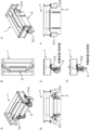
- FIG. 5 is a schematic diagram showing the roller conveyor around the mounting point of the stopping device; 5A to 5F show the case where the stopping device is in the standby state (recessed state), and FIG. 5G shows the case where the stopping device is in the operating state (out state).
- 5A is a perspective view seen from the upstream side
- FIG. 5B is a top view
- FIG. is a perspective view seen from the downstream side
- FIG. 5D is a plan view (front view) seen from the upstream side
- FIG. 5F is a plan view (rear view) seen from the downstream side.
- FIG. 5G is a right side view in the direction from the upstream side to the downstream side.
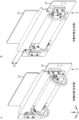
- FIG. 6 is a perspective view showing a standby state (recessed state) and an operating state (extended state) of the stopping device.
- FIG. 6A shows the case where the stopping device is in the standby state (recessed state)
- FIG. 6B shows the case where the stopping device is in the operating state (out state).
- An XYZ Cartesian coordinate system is shown in FIGS. 1-3 and 6 for clarity of directional relationships.
- the X direction is the direction (horizontal direction) along the movement direction DR shown in FIG. 1A in which the object moves by the roller conveyor CV
- the Z direction is the height direction (vertical direction) orthogonal to the X direction.
- the Y direction is a direction (width direction and depth direction) orthogonal to the X direction and the Z direction.
- the roller conveyor CV in the embodiment includes, for example, a conveyor body 1, a stopping device 2, and a control device 3, as shown in FIGS. 1 and 6.
- the conveyor main body 1 is a device that forms a movement path (conveyance path) along which a predetermined object (conveyed object) moves (conveys).
- One direction is defined as a moving direction DR, and the object is moved over the plurality of rollers 11 as the moving path.
- the plurality of rollers 11 are sequentially arranged side by side along the X direction as the one direction.
- FIG. 1 shows a portion of the conveyor body 1 having eight rollers 11-1 to 11-8, and the remaining portion is omitted.
- the plurality of rollers 11 are arranged at predetermined intervals (first intervals) in a direction perpendicular to the one direction (the Y direction in the example shown in FIG.
- first and second frames 12-1 and 12-2 which are plate-shaped members.
- Each of the first and second frames 12-1 and 12-2 extends Y from each end in the vertical direction (the Z direction in the example shown in FIG. 1) outward with respect to the juxtaposed plurality of rollers 11. 121-1, 122-1; 121-2, 122-2 extending along the direction.
- the flanges 121-1, 122-1 In the first and second frames 12-1, 12-2, which are plate-like members elongated along the X direction, the flanges 121-1, 122-1; The strength is improved in each of the Y and Z directions, which are two directions perpendicular to the direction.
- the plurality of rollers 11 includes a plurality of driving rollers 11a that generate their own driving force to rotate, and a plurality of driven rollers 11b that rotate by driving force from others.
- the plurality of driving rollers 11a are arranged at predetermined intervals (second intervals) along the one direction, and one or a plurality of driven rollers 11b are arranged between the adjacent driving rollers 11a. .
- the plurality of drive rollers 11a (11a-3, 11a-6) are arranged every two, and two driven rollers 11b (11b- 1, 11b-2; 11b-4, 11b-5; 11b-7, 11b-8) are provided.
- the driving roller 11a is, for example, a motorized roller incorporating a motor that is driven by being supplied with power.
- a roller conveyor motor roller used in the roller conveyor CV is known, and is disclosed in, for example, the aforementioned Patent Document 1 and International Publication No. 2009/139068.
- This motor roller is rotatably mounted on a pair of first and second shaft bodies fixed to a pair of first and second frames 12-1 and 12-2 via bearing members such as bearings. It comprises a cylindrical roller tube (drum) closed at both ends by a pair of attached first and second side plates. Inside the roller tube are a built-in motor mounted on an inner frame fixed to one of the first and second shafts, for example, the first shaft, and a reducer mounted on the output shaft of the built-in motor.
- the roller tube is attached and fixed to the output shaft of the speed reducer.
- the first shaft fixed to the built-in frame is hollow, and a cable (wiring) having one end connected to the control device 3 is passed through the hollow interior from the outside. The other end is connected to the built-in motor.
- the built-in motor is driven by electric power supplied by the cable, and the driving force generated by the built-in motor is transmitted to the roller tube via the speed reducer, thereby driving the roller tube to the first and second roller tubes. Rotate around the axis with the shaft as the axis of rotation.
- the drive roller 11a is a motorized roller with a built-in motor.
- the drive roller 11a is equipped with an external motor, and the driving force of the external motor is applied to the roller by, for example, a pulley and a belt, or by, for example, a gear. It may be of a type that transmits to and drives the roller.
- the driven roller 11b is publicly known, and is disclosed, for example, in Patent Document 1 and International Publication No. 2009/139068.
- the driven roller 11b is rotatable on a pair of first and second shafts fixed to a pair of first and second frames 12-1 and 12-2 via bearing members such as bearings. It comprises a cylindrical roller tube (drum) closed at both ends by a pair of first and second side plates attached to the drum. Such a driven roller 11b is rotated by the frictional force with the object moved by the driving roller 11a.
- the driving roller 11a and the driven roller 11b each have a pulley on which a belt is stretched at one end thereof, and the driving force of the driving roller 11a is applied to the pulley, the belt and the driven roller 11b of the driving roller 11a. is transmitted to the driven roller 11b via the pulley of , and the driven roller 11b is rotated.
- the stopping device 2 is a device that stops the object moving on the movement path. After stopping the object, the stopping device 2 can release the stop.
- the movement path is formed by a plurality of rollers 11 on the conveyor body 1 .
- the stopping device 2 includes a stopping member 21 which is a member for stopping the object, and a cam mechanism for causing the stopping member 21 to appear and disappear with respect to the moving path. and a part.
- the cam mechanism comprises a grooved cam 22 forming a recessed or through-opening cam groove 222 , and a cam follower 23 guided by the cam groove 222 and engaged with the stop member 21 .
- the cam groove 222 has an arc shape in a plane defined by a first straight line along the moving direction DR of the moving path and a second straight line along the retracting direction.
- the movement direction DR is the X direction
- the first straight line is a straight line parallel to the X axis
- the appearing/retracting direction is the Z direction
- the second straight line is a straight line parallel to the Z-axis
- the plane formed by the first and second straight lines is the XZ plane (a plane parallel to the XZ plane).
- the protruding/retracting part has a drive part that drives the grooved cam 22 around the axis, passing through the eccentric point EP that is eccentric from the center point CP of the arc shape and along the normal direction of the plane as the rotation axis. Prepare more.
- the normal direction of the plane is the Y direction
- the third straight line is parallel to the Y axis.
- the drive unit is a motor roller that incorporates a motor and is for a roller conveyor.
- the stopping member 21 is a plate-like member.
- the stop member 21 includes a first surface portion 211 that forms a flat first surface parallel to the YZ plane, and is bent about 90 degrees from the first surface portion 211 in the X direction, and further: A stepped portion 212 that extends by bending about 90 degrees in the Z direction, a second surface portion 213 that extends from the stepped portion 212 and forms a flat second surface parallel to the YZ plane, and a Y A pair of first and second rail retainers 214-1, 214-2 extending in the Z direction from respective ends of the direction, and first and second rail retainers 214-1, 214-2, respectively.
- the plate-shaped first rail 24-1 has one Y-direction end bent about 90 degrees in the X-direction to cover the Y-direction outer end surface of the first rail holding portion 214-1. Therefore, the first rail 24-1 has a substantially L shape in a cross section parallel to the XY plane (cross section of the XY plane).
- a second rail 24-2 which is a plate-like member elongated in the Z direction, is fixed to the second rail holding portion 214-2 with screws, for example. 2 Hold rail 24-2.
- One end in the Y direction of the plate-shaped second rail 24-2 is bent about 90 degrees in the X direction to cover the outer end face in the Y direction of the second rail holding portion 214-2. Therefore, the second rail 24-2 has a substantially L-shaped cross section in the XY plane.
- the stopping device 2 includes a pair of first and second rail guides 25-1 and 25-2 which are columnar members. Each one side surface of each of the first and second rail guides 25-1 and 25-2 is formed with an inwardly recessed groove extending in the direction of extension of the columnar shape.
- the first and second rail guides 25-1 and 25-2 have a Y-direction length from the first rail holding portion 214-1 to the second rail holding portion 214-2 so that the grooves face each other. are fixed to the base plate 27 by a pair of first and second guide mounting plates 26-1 and 26-2, respectively, with screws, for example, by aligning the extension direction of the column with the Z direction at intervals (fourth intervals) according to installed.
- the first rail 24-1 held by the first rail holding portion 214-1 is bent at an angle of about 90 degrees, and the one end thereof is attached to the bottom of the groove.
- a portion of the Y-direction outer end of the second rail guide 25-2 is slidably fitted so as to face each other, and is held by a second rail holding portion 214-2 in the groove of the second rail guide 25-2.
- the second rail 24-2 is slidably fitted at a portion of its Y-direction outer end so that the one end bent about 90 degrees faces the bottom surface of the groove. .
- the grooved cam 22 is configured with a pair of first and second grooved cams 22-1 and 22-2 in the examples shown in FIGS. Since these first and second grooved cams 22-1 and 22-2 are of the same shape, the grooved cam 22 will be described below mainly with reference to FIG. 4A.
- the grooved cam 22 includes a grooved cam body 221 which is a plate-like member with a circular part cut away.
- an arc-shaped cam groove 222 of a penetrating opening is formed.
- a shaft insertion opening 223 is formed as a through opening for inserting the shaft of the roller 29 .
- the arc-shaped center point CP coincides with the center point if the grooved cam main body 221 were to be circular without notching.
- the length of the cam groove 222 in the circumferential direction (the size of the central angle of the arc), the radius of the cam groove 222, and the position of the eccentric point EP are determined by the position of the first surface portion 211 of the stop member 21 relative to the movement path. It is appropriately set according to the haunt length.
- the base plate 27 is a plate-like member.
- the base plate 27 is rectangular in one example.
- the pair of first and second rails 24-1, 24-2 respectively held by the pair of first and second rail holding portions 214-1, 214-2 of the stop member 21 are , a pair of first and second rail guides 25-1, 25-2 attached to the base plate 27, and slidably fitted into the grooves.
- the first grooved cam 22-1 can pass through in the Z direction.
- a first grooved cam passing opening 271-1 is formed as a rectangular through opening extending to the second rail holding portion 214-1 in the space between the first and second rail holding portions 214-1 and 214-2.
- a second grooved cam passage opening 271-2 which is a rectangular through opening extending in the Z direction, is formed in order to allow the passage of the second grooved cam 22-2. Interference with the first rail holding portion 214-1 and the first rail 24-1 occurs between the first grooved cam passing opening 271-1 and the first rail guide 25-1 during the movement of the stopping member 21.
- a plate-like first shaft support member 28-1 having a substantially L-shaped cross section in the XY plane is attached to the base plate 27 at one end of the substantially L-shaped by fixing with a screw, for example, so as to prevent this from occurring. .
- a first shaft support opening 281 which is a through opening for supporting the shaft body of the motor roller 29 as an example of the drive unit, is provided. -1 is formed.
- the second rail holding portion 214-2 and the second rail 24-2 are held during the retracting movement of the stop member 21.
- a plate-shaped second shaft support member 28-2 having a substantially L-shaped cross section in the XY plane is attached to the base plate 27 at one end of the substantially L-shaped so as not to interfere with the base plate 27 by, for example, screws. ing.
- a second shaft support opening 281 which is a through opening for supporting the shaft body of the motor roller 29 as an example of the drive unit. -2 is formed.
- the motor roller 29 corresponds to an example of the drive unit, and is for a roller conveyor used in the roller conveyor CV in this embodiment.
- the motor roller 29 is, for example, a pair of first and second side plates rotatably attached to a pair of first and second shafts via bearing members such as bearings, similar to the driving roller 11a.
- a cylindrical roller tube (drum) closed at both ends with a roller tube, and inside the roller tube, one of the first and second shafts, for example, an inner frame fixed to the first shaft and a speed reducer attached to the output shaft of the built-in motor are accommodated, and the roller tube is attached and fixed to the output shaft of the speed reducer.
- the first shaft fixed to the built-in frame is hollow, and a cable (wiring) having one end connected to the control device 3 is passed through the hollow interior from the outside. The other end is connected to the built-in motor.
- the built-in motor is driven by electric power supplied by the cable, and the driving force generated by the built-in motor is transmitted to the roller tube via the speed reducer, thereby driving the roller tube to the first and second roller tubes. Rotate around the axis with the shaft as the axis of rotation.
- the motorized rollers 29 used in this stopping device 2 are shorter in length than the rollers 11 used in the conveyor body 1 .
- the motor roller 29 is driven by the first shaft through the first grooved cam 22-1 by inserting the first shaft into the first shaft insertion opening 223-1 of the first grooved cam 22-1. is fixed to the first shaft support member 28-1 at the first shaft support opening 281-1, and the second shaft is inserted into the second shaft insertion opening 223-2 of the second grooved cam 22-2.
- the second shaft body is fixed to the second shaft member 28-2 at the second shaft support opening 281-2 through the second grooved cam 22-2 by inserting it. This allows the pair of first and second grooved cams 22-1, 22-2 to pass through the pair of first and second grooved cam passage openings 271-1, 271-2, respectively.
- a grooved cam 22 - 1 , a motor roller 29 and a second grooved cam 22 - 2 are attached to the base plate 27 .
- One end of the roller tube of the motor roller 29 is fixed to the first grooved cam 22-1 by screws, for example, and the other end is fixed to the second grooved cam 22-2 by screws, for example. It is attached.
- the first grooved cam 22-1 is attached to one end of the roller tube of the motor roller 29 so that the first grooved cam main body 221-1 is parallel to the XZ plane. is a first straight line along the movement direction DR (the X direction in the examples shown in FIGS. 1 to 6) of the movement path and a second straight line along the appearance direction (the Z direction in the examples shown in FIGS. 1 to 6).
- the plane formed by the straight line (the XZ plane in the example shown in FIGS. 1 to 6) has an arc shape.
- the second grooved cam 22-2 is attached to the other end of the roller tube of the motor roller 29 so that the second grooved cam main body 221-2 is parallel to the XZ plane.
- the plane formed by the straight line (the XZ plane in the example shown in FIGS. 1 to 6) has an arc shape.
- the cam follower 23 is configured with a pair of first and second cam followers 23-1, 23-2 in the examples shown in FIGS. Since these first and second cam followers 23-1 and 23-2 have the same shape, they will be described as cam follower 23 mainly with reference to FIG. 4B.
- the cam follower 23 includes a cylindrical shaft portion 232 and a cylindrical follower attached to one end of the shaft portion 232 so as to be rotatable with respect to the shaft portion 232 via, for example, a needle bearing. and a main body 231 . Therefore, the diameter of the shaft portion 232 is shorter than the diameter of the follower body 231 .
- the diameter of the follower main body 231 is slightly shorter than the radial length (width) of the cam groove 222 so that it fits into the cam groove 222 so as to be movable.
- the first cam follower 23-1 is guided by the first cam groove 222-1 of the first grooved cam 22-1 and engaged with the stop member 21.
- the second cam follower 23-2 is guided by the second cam groove 222-2 of the second grooved cam 22-2 and engaged with the stop member 21.
- the first follower main body 231-1 of the first cam follower 23-1 is movably fitted into the first cam groove 222-1 of the first grooved cam 22-1,
- the other end of the first shaft portion 232-1 of the one cam follower 23-1 is attached to the first cam follower holding portion 215-1 of the stop member 21 by being fixed with screws, for example.
- the second follower main body 231-2 of the second cam follower 23-2 is movably fitted into the second cam groove 222-2 of the second grooved cam 22-2, and the second follower body 231-2 of the second cam follower 23-2
- the other end of the two-shaft portion 232-2 is attached to the second cam follower holding portion 215-2 of the stopping member 21 by being fixed with screws, for example.
- first and second rails 24-1, 24-2, first and second rail guides 25-1, 25-2, first and second guide mounting plates 26-1, 26-2, first and second The two shaft support members 28-1, 28-2, the motor roller 29, the first and second grooved cams 22-1, 22-2, and the first and second cam followers 23-1, 23-2 are configured to It constitutes an example of the part and corresponds to an example of the haunting part.
- First and second rails 24-1, 24-2, first and second rail guides 25-1, first and second grooved cams 22-1, 22-2, and first and second cam followers 23- 1 and 23-2 constitute an example of the cam mechanism and correspond to an example of the cam mechanism.
- the first and second grooved cams 22-1, 22-2 correspond to an example of so-called driving joints
- the first and second rails 24-1, 24-2 and the first and second cam followers 23-1, 23 -2 corresponds to an example of a so-called driven joint
- the first and second rail guides 25-1 and 25-2 correspond to an example of a so-called fixed joint.
- the first and second rail holding portions 214-1 and 214-2 that hold the first and second rails 24-1 and 24-2 may also be included in the retractable portions.
- the first and second rail retainers 214-1, 214-2 are included in the driven joint.
- the stopping device 2 uses the first and second sensors to detect the moving state of the grooved cam 22, or the moving state of the first grooved cam 22-1 in the example shown in FIGS. It further includes 30-1, 30-2, a sensor holding portion 31, and first and second sensor dogs 32-1, 32-2.
- the first and second sensors 30-1 and 30-2 are sensors for detecting the rotational position of the first grooved cam 22-1 as the moving state of the first grooved cam 22-1. type proximity sensor.
- the sensor holding portion 31 is a plate-like member having a substantially L shape in a cross section parallel to the XZ plane (cross section of the XZ plane), and holds the first and second sensors 30-1 and 30-2.
- the sensor holding section 31 sequentially arranges the first and second sensors 30-1 and 30-2 in the X direction on one end of the substantially L shape, thereby While holding the second sensors 30-1 and 30-2, the motor roller 29 is positioned below the motor roller 29 in the Z direction so that the first and second sensors 30-1 and 30-2 face the first grooved cam 22-1.
- the substantially L-shaped other end is fixed to the base plate 27 by screws, for example.
- the first sensor dog 32-1 is a member for operating the first sensor 30-1, and the second sensor dog 32-2 is a member for operating the second sensor 30-2.
- the first and second sensor dogs 32-1 and 32-2 are respectively connected to the first grooved cam 22-1.
- a short shaft made of metal (including alloy) is used. It is a high columnar member.
- the first sensor dog 32-1 is located at a position (first position) facing the first sensor 30-1 as shown in FIG. , it is fixed and attached to the first grooved cam body 221-1 of the first grooved cam 22-1, for example, by screws.
- the second sensor dog 32-2 is in a position (second position) facing the second sensor 30-2 as shown in FIG. , it is fixed and attached to the first grooved cam body 221-1 of the first grooved cam 22-1, for example, by screws.
- the stopping member 21 is retracted from the movement path in the standby state (recessed state) shown in FIG. is arranged with respect to the path of movement so as to exit to the
- the moving path is formed by the plurality of rollers 11 in the conveyor body 1, between two adjacent rollers 11 among the plurality of rollers 11 and between the plurality of rollers 11 At least one of the outer sides of the rollers 11 located at the ends of the two rollers 11-1 and 11-2 adjacent to each other in the examples shown in FIGS.
- the stop member 21 is retracted from the movement path formed by the plurality of rollers 11 in the standby state, and as shown in FIG.
- first and second stop device holding portions 13-1 and 13-2 are plate-like members of a substantially right-angled triangular shape, and each end of each of the two sides sandwiching the right angle is Each is bent at approximately 90 degrees. Therefore, the first and second stopping device holding portions 13-1 and 13-2 are substantially L-shaped in cross section along the XZ plane and substantially L-shaped in cross section along the XY plane.
- the first stopping device holding portion 13-1 is attached to the flange portion 122-1 of the first frame 12-1 at one end of the substantially L-shaped cross section of the XZ plane, for example, by screwing,
- the second stopping device holding portion 13-2 is fixed to the flange portion 122-2 of the second frame 12-2 with screws, for example, at one end of the substantially L-shaped cross section of the XZ plane.
- the first stopping device holding portion 13-1 is provided at one end of the substantially L-shaped cross section in the XY plane so that the stopping member 21 can appear and retract with respect to the moving path.
- the second stopping device holding portion 13-2 is fixed to the base plate 27 with screws, for example, at one end of the substantially L-shaped section in the XY plane. installed.
- the control device 3 is a device that is connected to each driving roller 11a of the conveyor body 1 and controls each driving roller 11a.
- the control device 3 rotates the drive roller 11a at a predetermined rotational speed in response to, for example, a control signal from a host system (not shown) of the roller conveyor CV or an input from an operation panel (not shown) of the control device 3. , or control to reversely rotate the driving roller 11a at a predetermined rotational speed. Forward rotation is the direction of rotation of the drive roller 11a that moves the object in the movement direction DR.
- a control device 3 is publicly known, and is disclosed, for example, in Patent Document 1 and International Publication No. 2013/057767.
- the stopping device 2 uses the motorized roller 29 as an example of the drive unit, so the control device 3 controls the motorized roller 29 of the stopping device 2 and the first and second sensors 30-1. , 30-2, and controls the motor roller 29 according to detection signals from the first and second sensors 30-1 and 30-2.
- the control device 3 causes the second sensor
- the motor roller 29 of the stopping device 2 is controlled to rotate forward until a detection signal is received from 30-2.
- the motor roller 29 rotates forward. That is, the built-in motor of the motor roller 29 is driven, and the roller tube of the motor roller 29 is connected to the first and second shaft support members 28-1 and 28-2 via the speed reducer of the motor roller 29.
- the fixed motor roller 29 rotates forward with the first and second shafts as the rotation axis.
- the first and second grooved cams 22-1 and 22-2 fixed to the roller tube of the motor roller 29 are driven. That is, the first and second groove cams 22-1 and 22-2 are eccentric points EP that are eccentric from the center points CP-1 and CP2 of the arc shapes of the first and second cam grooves 222-1 and 222-2. -1 and EP-2 and rotates about the third straight line along the normal direction (Y direction) of the XZ plane as the rotation axis.
- the first and second grooved cams 22-1, 22-2 rotate, the first and second cam followers 23-1, 23-2 respectively move into the first and second cam grooves 222-1, 222-2. be guided and moved.
- first and second follower bodies 231-1, 231-2 of the first and second cam followers 23-1, 23-2 fitted in the first and second cam grooves 222-1, 222-2 respectively Each moves along the first and second cam grooves 222-1, 222-2 respectively from one end to the other end in the circumferential direction, thus the first and second cam followers 23-1, 23-2
- the first and second shaft portions 232-1 and 232-2 of the are also moved.
- This movement is caused by the first and second cam follower retainers 215 fixedly attached to the first and second shafts 232-1, 232-2 of the first and second cam followers 23-1, 23-2, respectively.
- the movement of the stop member 21 is regulated (guided) in the Z direction by the first and second rail guides 25-1 and 25-2, and the stop member 21 is set at a predetermined position as shown in FIG. After moving in the Z direction by the length ST, the first surface portion 211 of the stopping member 21 appears on the moving path. Then, when the second sensor 30-2 detects the second sensor dog 32-2, the second sensor 30-2 transmits a detection signal to the control device 3, and in response to receiving this detection signal, the control device 3 As described above, the forward rotation of the motor roller 29 is stopped.
- control device 3 confirms the detection of the first sensor dog 32-1 by the first sensor 30-1 before starting the forward rotation of the motor roller 29, so that the stopping device 2 enters the standby state. You can check that there is
- the predetermined length ST which is the amount of movement of the stopping member 21, can be adjusted by adjusting the position of the second sensor dog 32-2.
- the predetermined length ST can also be adjusted by adjusting the drive time for forward rotation.
- the control device 3 when receiving an instruction to the standby state (down state) from the host system or the operation panel, the control device 3 receives a detection signal from the second sensor 30-2.
- the motor roller 29 of the stopping device 2 is controlled so as to rotate in the reverse direction until it is stopped.
- the motor roller 29 is reversed. That is, the built-in motor of the motor roller 29 is driven, and the roller tube of the motor roller 29 is connected to the first and second shaft support members 28-1 and 28-2 via the speed reducer of the motor roller 29.
- the first and second shafts of the fixed motor roller 29 are rotated in reverse.
- the first and second grooved cams 22-1, 22-2 fixed to the roller tube of the motor roller 29 are driven. That is, the first and second groove cams 22-1 and 22-2 are eccentric points EP that are eccentric from the center points CP-1 and CP2 of the arc shapes of the first and second cam grooves 222-1 and 222-2. -1 and EP-2 and rotates about the third straight line along the normal direction (Y direction) of the XZ plane as the rotation axis.
- the first and second grooved cams 22-1, 22-2 rotate, the first and second cam followers 23-1, 23-2 respectively move into the first and second cam grooves 222-1, 222-2. be guided and moved.
- first and second follower bodies 231-1, 231-2 of the first and second cam followers 23-1, 23-2 fitted in the first and second cam grooves 222-1, 222-2 respectively Each moves along the first and second cam grooves 222-1, 222-2, respectively, from each other end to each one end in the circumferential direction, thus the first and second cam followers 23-1, 23-2
- the first and second shaft portions 232-1 and 232-2 of the are also moved.
- This movement is caused by the first and second cam follower retainers 215 fixedly attached to the first and second shafts 232-1, 232-2 of the first and second cam followers 23-1, 23-2, respectively.
- the movement of the stop member 21 is regulated (guided) in the Z direction by the first and second rail guides 25-1 and 25-2, the stop member 21 moves in the Z direction, and the stop member 21
- the first surface portion 211 of is sunk from the moving path.
- the first sensor 30-1 detects the first sensor dog 32-1
- the first sensor 30-1 transmits a detection signal to the control device 3, and in response to receiving this detection signal, the control device 3 As described above, the reverse rotation of the motor roller 29 is stopped.
- control device 3 confirms the detection of the second sensor dog 32-2 by the second sensor 30-2 before starting the reverse rotation of the motor roller 29, so that the stopping device 2 is in the operating state. You can check that.
- roller conveyor CV and the stopping device 2 provided therewith in the embodiment do not require air supply because the stopping member 21 moves in and out with respect to the movement path by means of the cam mechanism.
- the stopping device is a fixed type such as a stopping plate, it is relatively inexpensive, but it is necessary to attach the stopping plate to the stopping position of the object or remove the stopping plate when restarting the movement of the stopped object.
- Such man-hours are required. Since the roller conveyor CV and the stopping device 2 move the stopping member 21 with respect to the moving path by means of a cam mechanism, such man-hours (labor) are not required.
- the cam mechanism can be realized with a simple structure.
- the roller conveyor CV and the stopping device 2 operate to prevent the groove cam from moving even when force is applied to the stopping member 21 from a direction intersecting the retracting direction (for example, the horizontal direction of the movement direction DR) by an object or the like. Since it is used, the stop member 21 can be retracted.
- the control device (controller) for the roller conveyor that controls the motor roller is used as the control device for the stopping device 2.
- the stopping member 21 can be retracted more reliably than the case where the stopping member 21 is retracted by its own weight. can be done.
- the roller conveyor CV and the stopping device 2 can stop.
- the member 21 can be sunk.
- the stopping member 21 Since the stopping member 21 has a stepped portion 212 that overlaps with the end surface of the base plate 27 at one end in the Z direction when viewed from the Z direction (protrusive/retractable direction), a problem occurs in the first sensor 30-1 for detecting the standby state. Even in this case, in the roller conveyor CV and the stopping device 2, the stepped portion 212 of the stopping member 21 comes into contact with the end surface of the base plate 27, so that the movement of the stopping member 21 can be stopped. Therefore, the roller conveyor CV and the stopping device 2 have a fail-safe function. When the stepped portion 212 comes into contact with the end surface of the base plate 27, the motor roller 29 is loaded. The contact can be detected, and the reverse driving of the motor roller 29 can be stopped.
- a roller conveyor CV equipped with the stopping device 2 can be provided.
- the stopping member 21 is put out on the movement path so that the object can be moved in the middle of the plurality of rollers 11 at the necessary timing.
- the object can be stopped, and by retracting the stop member 21 from the movement path, the object can be moved again at the required timing.
- the stop member 21 is put out on the moving path so that the object can be moved at the end of the plurality of rollers 11 as needed. In addition, by retracting the stop member 21 from the moving path, the object can be moved again at the necessary timing.
- the roller conveyor CV is a controller 3 that controls the motor rollers 11a of the roller conveyor CV, and can also control the drive section of the stopping device 2 (motor roller 29 as an example). There is no need to separately prepare a control device for control.
- FIG. 7 is a diagram for explaining an example of operation in the roller conveyor provided with the stopping device.
- FIG. 7A is a diagram showing movement of an object (first object Ob-1) moved by the roller conveyor CV.
- FIG. 7B is a diagram showing how three first to third objects OB-1 to Ob-3 are stored in the moving path of the roller conveyor CV.
- FIG. 7C restarts the movement of the first object Ob-1 positioned at the head (most downstream) among the three stored first to third objects Ob-1 to Ob-3 shown in FIG. 7B. It is a figure which shows the mode that it carried out.
- the stopping device 2 is arranged so that the stopping member 21 appears and disappears between two rollers 11 adjacent to each other among the plurality of rollers 11 .
- the stopping device 2 When the roller conveyor CV is operated to move (convey) the object Ob, the stopping device 2 is in a standby state (recessed state) as shown in FIG. transport route). Thereby, the object Ob moved by the plurality of rollers 11 continues its movement.
- the stopping device 2 When the roller conveyor CV is operated so as to store a plurality of objects Ob in the moving path, the stopping device 2 is put into an operating state (extended state) as shown in FIG. 7B, and the stopping member 21 is It's out on the road.
- the first object Ob-1 moved by the plurality of rollers 11 is stopped by the stop member 21 when it moves to the position of the stop member 21 of the stop device 2 .
- the first surface portion 211 of the stop member 21 is flat, so the first object Ob-1 By abutting the first surface portion 211, the inclination of the first object Ob-1 with respect to the movement direction DR is corrected.
- the second object Ob-2 moved by the plurality of rollers 11 moves to the position of the stopped first object Ob-1
- the first and second objects Ob-1 and Ob-2 are stored in the moving path.
- the third object Ob-3 moved by the plurality of rollers 11 moves to the position of the stopped second object Ob-2
- the third object Ob-3 comes into contact with the second object Ob-2 and moves toward the second object Ob-2.
- the first to third objects Ob-1 to Ob-3 are stored in the moving path.
- the driving roller 11a on which the first to third objects Ob-1 to Ob-3 are placed may be stopped while the first to third objects Ob-1 to Ob-3 are stored.
- the stopping device 2 When the roller conveyor CV is operated to move the plurality of stored objects Ob again, the stopping device 2 is changed from the operating state to the standby state, as shown in FIG. 7C, and the stopping member 21 moves Get off the road.
- the stopping member 21 disappears from the movement path, the leading (most downstream) first object Ob- 1 stopped by the stopping member 21 resumes its movement and is moved by the plurality of rollers 11 .
- the stopping device 2 is changed from the standby state to the operating state, whereby the second and third objects Ob-2 and Ob-3 are stored, and then the predetermined At the timing of , the stop device 2 is changed from the operating state to the standby state, and the movement of the second object Ob-2 may be resumed.
- the interval (fifth interval) between the first object Ob-1 and the second object Ob-2 can be adjusted.
- the interval (sixth interval) between the second object Ob-2 and the third object Ob-3 can also be adjusted.
- one stopping device 2 is arranged on the roller conveyor CV, but a plurality of stopping devices 2 may be arranged.
- the stop device 2 described above includes the grooved cam 22 that forms the arc-shaped cam groove 222 and is driven around the axis with the third straight line passing through the eccentric point EP as the rotation axis.
- the shape is not limited to this, and any shape may be used as long as the stopping member 21 can appear and disappear with respect to the movement path by the cam mechanism.
- FIG. 8 is a diagram for explaining a modified form of the grooved cam used in the stopping device.
- 8B is a plan view of the grooved cam
- FIG. 8A is a cross-sectional view seen from the II-II cross-sectional line shown in FIG. 8B
- FIG. 8C is a side view of the grooved cam.
- the cam mechanism may include a grooved cam 22a formed with a recessed or penetrating cam groove shown in FIG. 8 instead of the grooved cam 22 shown in FIG. and a cam follower 23 shown in FIG. 4B to be combined.
- the cam groove 222a has a shape including a substantially U shape with rounded corners in a plane defined by a first straight line along the moving direction DR of the moving path and a second straight line along the retracting direction.
- the movement direction DR is the X direction
- the first straight line is a straight line parallel to the X axis
- the appearance direction is the Z direction
- the second straight line is the Z axis.
- a plane formed by the first and second straight lines, which are parallel straight lines, is the XZ plane (a plane parallel to the XZ plane).
- the protruding/retracting portion passes through an eccentric point EPa that is biased to one side from the central position inside the substantially U-shape, and rotates the grooved cam 22a around the axis with a third straight line along the normal direction of the plane as a rotation axis.
- It further comprises a drive unit for driving.
- the normal direction of the plane is the Y direction
- the third straight line is a straight line parallel to the Y axis.
- the drive unit is a motor roller that incorporates a motor and is for a roller conveyor.
- the grooved cam 22a is configured with a pair of first and second grooved cams 22a-1 and 22a-2 in the same manner as described above. Since these first and second grooved cams 22a-1 and 22a-2 have the same shape, they will be described as the grooved cam 22a.
- the grooved cam 22a includes a grooved cam main body 221a which is a substantially D-shaped plate-like member in a plan view.
- a substantially U-shaped cam groove 222a with two rounded corners is formed in a plan view of the through opening.
- FIG. 8B a substantially U-shaped cam groove 222a with two rounded corners is formed in a plan view of the through opening.
- one end of the substantially U-shape is slightly extended outward obliquely.
- a motor roller 29 as an example of the drive unit is placed at the position of the eccentric point EPa that is biased to one side from the center position in the Z direction inside the substantially U-shape (in the example shown in FIG. 8B, biased to the lower side in the Z direction).
- a shaft body insertion opening 223a is formed as a through opening for the shaft body to be passed through.
- the size of the substantially U-shaped cam groove 222a (the length in the extending direction of the cam groove 222a) and the position of the eccentric point EPa depend on the protruding and retracting length of the first surface portion 211 of the stopping member 21 with respect to the moving path. is set appropriately.
- the center point CP of the arc coincides with the center point if the grooved cam main body 221 were assumed to be circular without notching, but the grooved cam 22a shown in FIG. However, the center point of the cam groove 221a does not coincide with the center point of the grooved cam main body 221a.
- the stopping device 2 is provided on the roller conveyor CV, but the stopping device 2 includes a plurality of rollers arranged side by side along one direction and a conveying belt stretched over the plurality of rollers. It may be provided on a belt conveyor with one or more sub-conveyors provided. Such a belt conveyor is publicly known, and is disclosed, for example, in Japanese Unexamined Patent Application Publication No. 2018-158826.
- the stop device 2 is installed between two sub-conveyors adjacent to each other among the plurality of sub-conveyors and in the sub-conveyor located at the end of the one or more sub-conveyors. and/or the outer side of the stop member.
- the object When the belt conveyor is provided with a stopping device 2 arranged in the middle of a plurality of sub-conveyors, the object can be stopped in the middle at a necessary timing by putting the stopping member 21 on the movement path, and By retracting the stop member 21 from the moving path, the object can be moved again at the required timing.
- the belt conveyor is provided with a stopping device 2 arranged outside at the end of a plurality of sub-conveyors, the object can be stopped at the end at the necessary timing by putting the stopping member 21 on the movement path. Also, by withdrawing the stop member 21 from the moving path, the object can be moved again at the required timing.
- a stopping device is a stopping device that stops an object moving on a moving path, and includes a stopping member that is a member for stopping the object, and a cam mechanism that moves the stopping member to the moving path. and a haunting portion for haunting.
- Such a stopping device does not require an air supply because the stopping member moves in and out with respect to the movement path by means of a cam mechanism.
- the cam mechanism includes a grooved cam forming a cam groove of a recess or a through opening, and a cam follower guided by the cam groove and engaged with the stopping member.
- the cam groove has an arc shape in a plane formed by a first straight line along the movement direction of the movement path and a second straight line along the projection/retraction direction, and the projection/retraction portion is arc-shaped.
- a drive unit that drives the grooved cam around the axis, passing through an eccentric point that is eccentric from the center of the grooved cam, with a third straight line along the normal direction of the plane as a rotation axis.
- the cam mechanism includes a grooved cam forming a cam groove of a recess or a through opening, and a cam follower guided by the cam groove and engaged with the stopping member.
- the cam groove has a shape including a U-shape with rounded corners in a plane formed by a first straight line along the movement direction of the movement path and a second straight line along the retraction direction.
- the protruding/retracting portion passes through an eccentric point biased to one side from the central position inside the U-shape, and drives the grooved cam around the axis with a third straight line along the normal direction of the plane as a rotation axis.
- a drive unit is further provided.
- stopping devices use a grooved cam of a planar cam in which cam grooves are formed in the plane, so that the cam mechanism can be realized with a simple structure.
- the stopping device uses a grooved cam even when force is applied to the stopping member from a direction (for example, horizontal direction) intersecting the retracting direction by an object or the like, so that the stopping member can be retracted. .
- the drive unit is a motorized roller that incorporates a motor and is for a roller conveyor used in a roller conveyor.
- the motor roller for the roller conveyor is used as the drive unit, so the control device (controller) for the roller conveyor that controls the motor roller can be used as the control device for the stopping device.
- the control device that controls the motor roller of the roller conveyor can also control the driving portion of the stopping device (motor roller as an example), so the driving portion of the stopping device is controlled. There is no need to separately prepare a control device.
- a roller conveyor is a roller conveyor including a plurality of rollers arranged side by side along one direction, and between two rollers adjacent to each other among the plurality of rollers and between the plurality of rollers. any one of the above-described stopping devices arranged to project and retract the stopping member on at least one of the outer side of the roller located at the end of the rollers in the one direction.
- a belt conveyor is a belt conveyor comprising one or more sub-conveyors comprising a plurality of rollers arranged in parallel along one direction and a conveying belt stretched over the plurality of rollers, At least one of between two sub-conveyors adjacent to each other among a plurality of sub-conveyors, and the outer side of the sub-conveyor located at the end of the one or more sub-conveyors, 4. Further comprising a stop device according to any one of claims 1 to 3 arranged to extend and retract the stop member.
- roller conveyor and a belt conveyor equipped with any of the stopping devices described above.
- the roller conveyor and the belt conveyor are provided with a stopping device arranged in the middle, the object can be stopped in the middle at a necessary timing by putting the stopping member on the moving path, and the stopping member is removed from the movement path, the object can be moved again at the required timing.
- the roller conveyor and the belt conveyor are provided with a stop device arranged outside at the end, the object can be stopped at the end at a necessary timing by putting the stop member on the movement path, and By withdrawing the stop member from the movement path, the object can be moved again at the required timing.
- a stopping device a roller conveyor and a belt conveyor can be provided.
Landscapes
- Engineering & Computer Science (AREA)
- Mechanical Engineering (AREA)
- Rollers For Roller Conveyors For Transfer (AREA)
- Special Conveying (AREA)
- Transmission Devices (AREA)
Priority Applications (5)
| Application Number | Priority Date | Filing Date | Title |
|---|---|---|---|
| US18/721,407 US12479669B2 (en) | 2021-12-20 | 2021-12-20 | Stopper, roller conveyor, and belt conveyor |
| EP21968793.6A EP4446257A4 (en) | 2021-12-20 | 2021-12-20 | STOPPERS, ROLLER CONVEYORS AND BELT CONVEYORS |
| JP2022526353A JP7125192B1 (ja) | 2021-12-20 | 2021-12-20 | 停止装置、ローラコンベアおよびベルトコンベア |
| CN202180105152.6A CN118434644A (zh) | 2021-12-20 | 2021-12-20 | 停止装置、滚筒式输送机以及带式输送机 |
| PCT/JP2021/046977 WO2023119355A1 (ja) | 2021-12-20 | 2021-12-20 | 停止装置、ローラコンベアおよびベルトコンベア |
Applications Claiming Priority (1)
| Application Number | Priority Date | Filing Date | Title |
|---|---|---|---|
| PCT/JP2021/046977 WO2023119355A1 (ja) | 2021-12-20 | 2021-12-20 | 停止装置、ローラコンベアおよびベルトコンベア |
Publications (1)
| Publication Number | Publication Date |
|---|---|
| WO2023119355A1 true WO2023119355A1 (ja) | 2023-06-29 |
Family
ID=83004366
Family Applications (1)
| Application Number | Title | Priority Date | Filing Date |
|---|---|---|---|
| PCT/JP2021/046977 Ceased WO2023119355A1 (ja) | 2021-12-20 | 2021-12-20 | 停止装置、ローラコンベアおよびベルトコンベア |
Country Status (5)
| Country | Link |
|---|---|
| US (1) | US12479669B2 (https=) |
| EP (1) | EP4446257A4 (https=) |
| JP (1) | JP7125192B1 (https=) |
| CN (1) | CN118434644A (https=) |
| WO (1) | WO2023119355A1 (https=) |
Cited By (1)
| Publication number | Priority date | Publication date | Assignee | Title |
|---|---|---|---|---|
| EP4671168A3 (en) * | 2024-06-26 | 2026-03-18 | Google LLC | Compact control barrier system |
Citations (7)
| Publication number | Priority date | Publication date | Assignee | Title |
|---|---|---|---|---|
| JPH0218220A (ja) * | 1988-06-10 | 1990-01-22 | Rapistan Corp | コンベヤ装置のカムローラ装置 |
| JP2002255337A (ja) * | 2001-02-27 | 2002-09-11 | Teraoka Seiko Co Ltd | アキュムレーションコンベア及び包装機 |
| WO2009139068A1 (ja) | 2008-05-16 | 2009-11-19 | 株式会社協和製作所 | ローラコンベヤー用モータ内蔵ローラおよびそれを用いるローラコンベヤー装置 |
| WO2013057767A1 (ja) | 2011-10-20 | 2013-04-25 | 株式会社協和製作所 | モータ駆動装置およびこれを用いたローラコンベア装置 |
| JP5659745B2 (ja) * | 2010-12-03 | 2015-01-28 | 富士電機株式会社 | 自動販売機 |
| JP2018158826A (ja) | 2017-03-23 | 2018-10-11 | 株式会社協和製作所 | コンベヤ装置用ローラおよびコンベヤ装置 |
| JP2018177441A (ja) | 2017-04-11 | 2018-11-15 | 株式会社協和製作所 | ローラコンベア装置 |
Family Cites Families (22)
| Publication number | Priority date | Publication date | Assignee | Title |
|---|---|---|---|---|
| US2180163A (en) * | 1937-10-02 | 1939-11-14 | Redington Co F B | Butter feeder |
| US2926770A (en) * | 1957-01-22 | 1960-03-01 | Sperry Gyroscope Co Ltd | Article handling machine |
| US2993623A (en) * | 1959-02-27 | 1961-07-25 | Nat Steel Corp | Article handling apparatus |
| US4088221A (en) * | 1976-09-02 | 1978-05-09 | Simplimatic Engineering Co. | Stop apparatus for palletizers and the like |
| US4487309A (en) * | 1982-01-07 | 1984-12-11 | Dorner Mfg. Corp. | Conveyor system |
| FI94405C (fi) * | 1987-03-13 | 1995-09-11 | Tsubakimoto Chain Co | Siirtolaitteisto |
| US5178258A (en) * | 1990-01-25 | 1993-01-12 | Smalley Alfred E | Inertial conveyor system |
| US5211276A (en) | 1992-06-23 | 1993-05-18 | Tekno Inc. | Stop for conveyor |
| JP2001106331A (ja) * | 1999-10-08 | 2001-04-17 | Kyowa Seisakusho:Kk | 搬送制御システム |
| US6763930B2 (en) * | 2002-03-14 | 2004-07-20 | Rapistan Systems Advertising Corp. | Accumulation conveyor assembly |
| JP4538212B2 (ja) * | 2002-10-24 | 2010-09-08 | 株式会社三共製作所 | 駆動機構およびこれを用いた移動テーブル |
| US20050139450A1 (en) * | 2003-12-30 | 2005-06-30 | International Product Technology, Inc. | Electrical part processing unit |
| US7232025B1 (en) * | 2006-05-25 | 2007-06-19 | Siemens Energy & Automation, Inc. | Electromagnetic conveyor stop |
| DE102010001356B3 (de) | 2010-01-29 | 2012-10-25 | Bito-Lagertechnik Bittmann Gmbh | Durchlaufregal mit Separiervorrichtung |
| US8083049B2 (en) * | 2010-02-08 | 2011-12-27 | Machine Solutions Providers, Inc. | Motorized backstop |
| SE538606C2 (sv) * | 2012-03-28 | 2016-09-27 | Eton Ab | Styrskensdel för en transportör och transportör innefattandes en sådan styrskensdel |
| US9004259B1 (en) * | 2012-09-14 | 2015-04-14 | Intelligrated Headquarters, Llc | Repositionable extendable stop |
| US9290333B2 (en) * | 2013-03-15 | 2016-03-22 | Intelligrated Headquarters, Llc | Transfer conveyor |
| MX2018002714A (es) * | 2016-12-13 | 2018-08-15 | Hirata Spinning | Mesa giratoria. |
| US10407252B1 (en) * | 2018-04-25 | 2019-09-10 | Nissan North America, Inc. | Conveyor assembly |
| WO2022196817A1 (en) * | 2021-03-19 | 2022-09-22 | Omron Corporation | System and method for controlling movement of a payload |
| US12168579B2 (en) * | 2023-01-19 | 2024-12-17 | Intelligrated Headquarters, Llc | Tote stop assembly and method of using the same |
-
2021
- 2021-12-20 EP EP21968793.6A patent/EP4446257A4/en active Pending
- 2021-12-20 CN CN202180105152.6A patent/CN118434644A/zh active Pending
- 2021-12-20 JP JP2022526353A patent/JP7125192B1/ja active Active
- 2021-12-20 WO PCT/JP2021/046977 patent/WO2023119355A1/ja not_active Ceased
- 2021-12-20 US US18/721,407 patent/US12479669B2/en active Active
Patent Citations (7)
| Publication number | Priority date | Publication date | Assignee | Title |
|---|---|---|---|---|
| JPH0218220A (ja) * | 1988-06-10 | 1990-01-22 | Rapistan Corp | コンベヤ装置のカムローラ装置 |
| JP2002255337A (ja) * | 2001-02-27 | 2002-09-11 | Teraoka Seiko Co Ltd | アキュムレーションコンベア及び包装機 |
| WO2009139068A1 (ja) | 2008-05-16 | 2009-11-19 | 株式会社協和製作所 | ローラコンベヤー用モータ内蔵ローラおよびそれを用いるローラコンベヤー装置 |
| JP5659745B2 (ja) * | 2010-12-03 | 2015-01-28 | 富士電機株式会社 | 自動販売機 |
| WO2013057767A1 (ja) | 2011-10-20 | 2013-04-25 | 株式会社協和製作所 | モータ駆動装置およびこれを用いたローラコンベア装置 |
| JP2018158826A (ja) | 2017-03-23 | 2018-10-11 | 株式会社協和製作所 | コンベヤ装置用ローラおよびコンベヤ装置 |
| JP2018177441A (ja) | 2017-04-11 | 2018-11-15 | 株式会社協和製作所 | ローラコンベア装置 |
Non-Patent Citations (1)
| Title |
|---|
| See also references of EP4446257A4 |
Cited By (1)
| Publication number | Priority date | Publication date | Assignee | Title |
|---|---|---|---|---|
| EP4671168A3 (en) * | 2024-06-26 | 2026-03-18 | Google LLC | Compact control barrier system |
Also Published As
| Publication number | Publication date |
|---|---|
| US12479669B2 (en) | 2025-11-25 |
| US20250122028A1 (en) | 2025-04-17 |
| JP7125192B1 (ja) | 2022-08-24 |
| EP4446257A4 (en) | 2025-01-15 |
| CN118434644A (zh) | 2024-08-02 |
| EP4446257A1 (en) | 2024-10-16 |
| JPWO2023119355A1 (https=) | 2023-06-29 |
Similar Documents
| Publication | Publication Date | Title |
|---|---|---|
| EP2403784B1 (en) | Multi-mode scroll cam conveyor system | |
| US8763790B1 (en) | Clean room roller conveyor with motors between and torquing drive roller pairs | |
| JP7125192B1 (ja) | 停止装置、ローラコンベアおよびベルトコンベア | |
| JP2010159161A (ja) | 組付コンベア装置 | |
| CN114394395A (zh) | 一种输送系统及输送方法 | |
| CN102189437B (zh) | 托盘输送装置和托盘输送方法 | |
| US20240025665A1 (en) | Conveyor system with at least three axle devices | |
| WO2009113160A1 (ja) | 基板搬送装置及び基板搬送方法 | |
| CA3169113A1 (en) | Conveyor system with at least three axle devices | |
| JP4893346B2 (ja) | シート状物の延伸機 | |
| JP2024082585A (ja) | 搬送システムおよび搬送システムに用いられるガイド機構 | |
| US20240025666A1 (en) | Conveyor with swing offset axis device | |
| US12151901B2 (en) | Conveyor with linear axis devices | |
| KR101267323B1 (ko) | 5축 링크 기구를 구비한 엘씨디 글라스 마크로 검사장치 | |
| CA2415180A1 (en) | Unstable article conveying device with diverter | |
| CA3184787A1 (en) | Conveyor system with linear axle assemblies | |
| JPH0733246A (ja) | 物品把持機構における拡縮装置 | |
| WO2001055012A1 (fr) | Dispositif transporteur a rouleaux | |
| CA3169116A1 (en) | Conveyor system with pivot offset axle device | |
| JP2023088450A (ja) | カーブコンベア | |
| CN116237918A (zh) | 一种工业机器人 | |
| KR20230163214A (ko) | 일축 다헤드 로봇 | |
| WO2002032793A1 (fr) | Dispositif transporteur | |
| JP2005075292A (ja) | 走行レール設備を走行する機械式搬送装置 |
Legal Events
| Date | Code | Title | Description |
|---|---|---|---|
| WWE | Wipo information: entry into national phase |
Ref document number: 2022526353 Country of ref document: JP |
|
| 121 | Ep: the epo has been informed by wipo that ep was designated in this application |
Ref document number: 21968793 Country of ref document: EP Kind code of ref document: A1 |
|
| WWE | Wipo information: entry into national phase |
Ref document number: 202180105152.6 Country of ref document: CN |
|
| WWE | Wipo information: entry into national phase |
Ref document number: 2021968793 Country of ref document: EP |
|
| ENP | Entry into the national phase |
Ref document number: 2021968793 Country of ref document: EP Effective date: 20240709 |
|
| NENP | Non-entry into the national phase |
Ref country code: DE |
|
| WWP | Wipo information: published in national office |
Ref document number: 18721407 Country of ref document: US |
|
| WWG | Wipo information: grant in national office |
Ref document number: 18721407 Country of ref document: US |