WO2023113017A1 - フローティング型ディスクブレーキ装置 - Google Patents
フローティング型ディスクブレーキ装置 Download PDFInfo
- Publication number
- WO2023113017A1 WO2023113017A1 PCT/JP2022/046442 JP2022046442W WO2023113017A1 WO 2023113017 A1 WO2023113017 A1 WO 2023113017A1 JP 2022046442 W JP2022046442 W JP 2022046442W WO 2023113017 A1 WO2023113017 A1 WO 2023113017A1
- Authority
- WO
- WIPO (PCT)
- Prior art keywords
- brake device
- disc brake
- floating type
- type disc
- pad
- Prior art date
- Legal status (The legal status is an assumption and is not a legal conclusion. Google has not performed a legal analysis and makes no representation as to the accuracy of the status listed.)
- Ceased
Links
Images


















Classifications
-
- F—MECHANICAL ENGINEERING; LIGHTING; HEATING; WEAPONS; BLASTING
- F16—ENGINEERING ELEMENTS AND UNITS; GENERAL MEASURES FOR PRODUCING AND MAINTAINING EFFECTIVE FUNCTIONING OF MACHINES OR INSTALLATIONS; THERMAL INSULATION IN GENERAL
- F16D—COUPLINGS FOR TRANSMITTING ROTATION; CLUTCHES; BRAKES
- F16D55/00—Brakes with substantially-radial braking surfaces pressed together in axial direction, e.g. disc brakes
- F16D55/02—Brakes with substantially-radial braking surfaces pressed together in axial direction, e.g. disc brakes with axially-movable discs or pads pressed against axially-located rotating members
- F16D55/22—Brakes with substantially-radial braking surfaces pressed together in axial direction, e.g. disc brakes with axially-movable discs or pads pressed against axially-located rotating members by clamping an axially-located rotating disc between movable braking members, e.g. movable brake discs or brake pads
- F16D55/224—Brakes with substantially-radial braking surfaces pressed together in axial direction, e.g. disc brakes with axially-movable discs or pads pressed against axially-located rotating members by clamping an axially-located rotating disc between movable braking members, e.g. movable brake discs or brake pads with a common actuating member for the braking members
- F16D55/225—Brakes with substantially-radial braking surfaces pressed together in axial direction, e.g. disc brakes with axially-movable discs or pads pressed against axially-located rotating members by clamping an axially-located rotating disc between movable braking members, e.g. movable brake discs or brake pads with a common actuating member for the braking members the braking members being brake pads
- F16D55/226—Brakes with substantially-radial braking surfaces pressed together in axial direction, e.g. disc brakes with axially-movable discs or pads pressed against axially-located rotating members by clamping an axially-located rotating disc between movable braking members, e.g. movable brake discs or brake pads with a common actuating member for the braking members the braking members being brake pads in which the common actuating member is moved axially, e.g. floating caliper disc brakes
-
- F—MECHANICAL ENGINEERING; LIGHTING; HEATING; WEAPONS; BLASTING
- F16—ENGINEERING ELEMENTS AND UNITS; GENERAL MEASURES FOR PRODUCING AND MAINTAINING EFFECTIVE FUNCTIONING OF MACHINES OR INSTALLATIONS; THERMAL INSULATION IN GENERAL
- F16D—COUPLINGS FOR TRANSMITTING ROTATION; CLUTCHES; BRAKES
- F16D55/00—Brakes with substantially-radial braking surfaces pressed together in axial direction, e.g. disc brakes
- F16D55/02—Brakes with substantially-radial braking surfaces pressed together in axial direction, e.g. disc brakes with axially-movable discs or pads pressed against axially-located rotating members
- F16D55/22—Brakes with substantially-radial braking surfaces pressed together in axial direction, e.g. disc brakes with axially-movable discs or pads pressed against axially-located rotating members by clamping an axially-located rotating disc between movable braking members, e.g. movable brake discs or brake pads
- F16D55/224—Brakes with substantially-radial braking surfaces pressed together in axial direction, e.g. disc brakes with axially-movable discs or pads pressed against axially-located rotating members by clamping an axially-located rotating disc between movable braking members, e.g. movable brake discs or brake pads with a common actuating member for the braking members
- F16D55/225—Brakes with substantially-radial braking surfaces pressed together in axial direction, e.g. disc brakes with axially-movable discs or pads pressed against axially-located rotating members by clamping an axially-located rotating disc between movable braking members, e.g. movable brake discs or brake pads with a common actuating member for the braking members the braking members being brake pads
- F16D55/226—Brakes with substantially-radial braking surfaces pressed together in axial direction, e.g. disc brakes with axially-movable discs or pads pressed against axially-located rotating members by clamping an axially-located rotating disc between movable braking members, e.g. movable brake discs or brake pads with a common actuating member for the braking members the braking members being brake pads in which the common actuating member is moved axially, e.g. floating caliper disc brakes
- F16D55/2262—Brakes with substantially-radial braking surfaces pressed together in axial direction, e.g. disc brakes with axially-movable discs or pads pressed against axially-located rotating members by clamping an axially-located rotating disc between movable braking members, e.g. movable brake discs or brake pads with a common actuating member for the braking members the braking members being brake pads in which the common actuating member is moved axially, e.g. floating caliper disc brakes the axial movement being guided by open sliding surfaces, e.g. grooves
-
- F—MECHANICAL ENGINEERING; LIGHTING; HEATING; WEAPONS; BLASTING
- F16—ENGINEERING ELEMENTS AND UNITS; GENERAL MEASURES FOR PRODUCING AND MAINTAINING EFFECTIVE FUNCTIONING OF MACHINES OR INSTALLATIONS; THERMAL INSULATION IN GENERAL
- F16D—COUPLINGS FOR TRANSMITTING ROTATION; CLUTCHES; BRAKES
- F16D65/00—Parts or details
- F16D65/005—Components of axially engaging brakes not otherwise provided for
- F16D65/0056—Brake supports
-
- F—MECHANICAL ENGINEERING; LIGHTING; HEATING; WEAPONS; BLASTING
- F16—ENGINEERING ELEMENTS AND UNITS; GENERAL MEASURES FOR PRODUCING AND MAINTAINING EFFECTIVE FUNCTIONING OF MACHINES OR INSTALLATIONS; THERMAL INSULATION IN GENERAL
- F16D—COUPLINGS FOR TRANSMITTING ROTATION; CLUTCHES; BRAKES
- F16D65/00—Parts or details
- F16D65/005—Components of axially engaging brakes not otherwise provided for
- F16D65/0068—Brake calipers
-
- F—MECHANICAL ENGINEERING; LIGHTING; HEATING; WEAPONS; BLASTING
- F16—ENGINEERING ELEMENTS AND UNITS; GENERAL MEASURES FOR PRODUCING AND MAINTAINING EFFECTIVE FUNCTIONING OF MACHINES OR INSTALLATIONS; THERMAL INSULATION IN GENERAL
- F16D—COUPLINGS FOR TRANSMITTING ROTATION; CLUTCHES; BRAKES
- F16D65/00—Parts or details
- F16D65/02—Braking members; Mounting thereof
- F16D65/04—Bands, shoes or pads; Pivots or supporting members therefor
- F16D65/092—Bands, shoes or pads; Pivots or supporting members therefor for axially-engaging brakes, e.g. disc brakes
-
- F—MECHANICAL ENGINEERING; LIGHTING; HEATING; WEAPONS; BLASTING
- F16—ENGINEERING ELEMENTS AND UNITS; GENERAL MEASURES FOR PRODUCING AND MAINTAINING EFFECTIVE FUNCTIONING OF MACHINES OR INSTALLATIONS; THERMAL INSULATION IN GENERAL
- F16D—COUPLINGS FOR TRANSMITTING ROTATION; CLUTCHES; BRAKES
- F16D65/00—Parts or details
- F16D65/02—Braking members; Mounting thereof
- F16D65/12—Discs; Drums for disc brakes
- F16D65/122—Discs; Drums for disc brakes adapted for mounting of friction pads
-
- F—MECHANICAL ENGINEERING; LIGHTING; HEATING; WEAPONS; BLASTING
- F16—ENGINEERING ELEMENTS AND UNITS; GENERAL MEASURES FOR PRODUCING AND MAINTAINING EFFECTIVE FUNCTIONING OF MACHINES OR INSTALLATIONS; THERMAL INSULATION IN GENERAL
- F16D—COUPLINGS FOR TRANSMITTING ROTATION; CLUTCHES; BRAKES
- F16D65/00—Parts or details
- F16D65/14—Actuating mechanisms for brakes; Means for initiating operation at a predetermined position
- F16D65/16—Actuating mechanisms for brakes; Means for initiating operation at a predetermined position arranged in or on the brake
- F16D65/18—Actuating mechanisms for brakes; Means for initiating operation at a predetermined position arranged in or on the brake adapted for drawing members together, e.g. for disc brakes
- F16D65/183—Actuating mechanisms for brakes; Means for initiating operation at a predetermined position arranged in or on the brake adapted for drawing members together, e.g. for disc brakes with force-transmitting members arranged side by side acting on a spot type force-applying member
-
- F—MECHANICAL ENGINEERING; LIGHTING; HEATING; WEAPONS; BLASTING
- F16—ENGINEERING ELEMENTS AND UNITS; GENERAL MEASURES FOR PRODUCING AND MAINTAINING EFFECTIVE FUNCTIONING OF MACHINES OR INSTALLATIONS; THERMAL INSULATION IN GENERAL
- F16D—COUPLINGS FOR TRANSMITTING ROTATION; CLUTCHES; BRAKES
- F16D55/00—Brakes with substantially-radial braking surfaces pressed together in axial direction, e.g. disc brakes
- F16D2055/0004—Parts or details of disc brakes
- F16D2055/0008—Brake supports
-
- F—MECHANICAL ENGINEERING; LIGHTING; HEATING; WEAPONS; BLASTING
- F16—ENGINEERING ELEMENTS AND UNITS; GENERAL MEASURES FOR PRODUCING AND MAINTAINING EFFECTIVE FUNCTIONING OF MACHINES OR INSTALLATIONS; THERMAL INSULATION IN GENERAL
- F16D—COUPLINGS FOR TRANSMITTING ROTATION; CLUTCHES; BRAKES
- F16D55/00—Brakes with substantially-radial braking surfaces pressed together in axial direction, e.g. disc brakes
- F16D2055/0004—Parts or details of disc brakes
- F16D2055/0016—Brake calipers
Definitions
- the present invention relates to a floating type disc brake device.
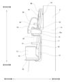
- FIG. 38 shows a floating-type disc brake device 100 of conventional structure, which is described in Japanese Utility Model Laid-Open No. 57-1922 (Patent Document 1).
- the disc brake device 100 includes a support 101, a caliper body 102, an inner pad 103 and an outer pad 104.
- the caliper body 102 supported on the support 101 is displaced in the axial direction, so that the rotor 105 that rotates with the wheel is clamped from both sides in the axial direction by the inner pad 103 and the outer pad 104 .
- the terms “axial,” “radial,” and “circumferential” refer to the axial, radial, and circumferential directions of a disc-shaped rotor that rotates with the wheel, unless otherwise specified. say the direction
- the widthwise outer side of the vehicle body is referred to as the axially outer side
- the widthwise central side of the vehicle body is referred to as the axially inner side
- the circumferential center side of the disc brake device is referred to as the circumferential inner side
- the circumferential both sides of the disc brake device are referred to as the circumferential outer side.
- the "incoming side” means the side where the rotor enters the caliper body
- the “outgoing side” means the side where the rotor exits the caliper body.
- the support 101 is fixed to the suspension device, and has a pair of guide portions 106 having an inverted U shape when viewed in the circumferential direction, and a circumferential connecting portion 107 connecting the pair of guide portions 106 in the circumferential direction. .
- Each of the pair of guide portions 106 includes an inner guide portion 108, an outer guide portion 109, and a caliper guide portion 110.
- the caliper guide portion 110 axially connects the radially outer ends of the inner guide portion 108 and the outer guide portion 109 .
- a support hole 111 is formed inside the caliper guide portion 110 .
- the support hole 111 opens on the inner side surface of the caliper guide portion 110 in the axial direction.
- the caliper body 102 has a bifurcated outer body portion 112 on its axial outer side and an inner body portion 113 on its axial inner side.
- the inner body portion 113 has a cylinder 114 .
- a piston 115 is fitted inside the cylinder 114 so as to be axially movable.
- the caliper body 102 is supported by a pair of slide pins 116 so as to be axially movable with respect to the support 101 .
- Each slide pin 116 has a base end fixed to the caliper body 102 and a front half slidably inserted into a support hole 111 provided in the caliper guide portion 110 .
- the inner pad 103 is arranged inside the rotor 105 in the axial direction, and is axially movably supported by the pair of inner guide portions 108 .
- the outer pad 104 is arranged axially outside the rotor 105 and supported axially movably with respect to the pair of outer guide portions 109 .
- pressurized oil is sent from the master cylinder to the cylinder 114, and the piston 115 presses the inner pad 103 against the inner side surface of the rotor 105 in the axial direction from top to bottom in FIG. Then, as a reaction to this pressing force, the caliper body 102 moves upward in FIG. The outer body portion 112 presses the outer pad 104 against the axial outer surface of the rotor 105 . As a result, the rotor 105 is strongly clamped from both sides in the axial direction, and braking is performed.
- the circumferential dimension of the outer body portion (claw portion) that constitutes the caliper body which is visible from the outside when the disc brake device is attached to the vehicle body, is increased. It is considered to cover the pair of guide portions that constitute the support from the outside in the axial direction.
- the outer body portion covers the pair of guide portions of the support from the outside in the axial direction, the wear of the inner and outer pads progresses and the caliper body moves axially inward with respect to the support, forming the guide portions. A gap between the outer guide portion and the outer body portion is reduced. Therefore, the outer guide portion and the outer body portion are likely to interfere with each other during braking.
- a metal plate pad clip is often attached to the outer guide to enable smooth axial movement of the outer pad. , may be arranged to protrude outward in the axial direction from the outer guide portion. Therefore, when such a pad clip is used, interference between the pad clip and the outer body portion is likely to occur.
- the present invention has been made to solve the above-mentioned problems.
- the object is to provide a braking device.
- a floating type disc brake device includes an inner pad, an outer pad, a support, and a caliper body.
- the inner pad is arranged axially inside the rotor.
- the outer pad is arranged axially outside of the rotor.
- the support is fixed to the vehicle body and axially movably supports the inner pad and the outer pad.
- the caliper body is supported axially movably with respect to the support.
- the support has an inner guide portion that axially movably supports the inner pad, and an outer guide portion that axially movably supports the outer pad on each of the outer circumferential sides. .
- the caliper body has a cylinder and has an inner body portion arranged axially inwardly of the rotor and an outer body portion that presses the outer pad during braking.
- the outer body portion has a through hole opened only in the axial direction in at least one of the portion axially facing the outer guide portion and the portion adjacent to the outer guide portion.
- the floating type disc brake device further includes a pad clip disposed between the outer pad and the outer guide portion, and a portion of the pad clip is inserted inside the through hole. can be made A portion of the pad clip that protrudes most outward in the axial direction can be inserted into the through hole.
- the through-hole may have a shape and size that allows a portion of the pad clip to be inserted almost without a gap.
- the outer pad has a convex ear portion that protrudes in the circumferential direction
- the outer guide portion includes a guide concave groove that can be engaged with the ear portion. and the through hole can be provided in a portion facing the inner space of the guide groove in the axial direction.
- the circumferential dimension of the through hole can be made larger than the radial dimension.
- the through hole may have a substantially polygonal opening shape when viewed in the axial direction.
- the opening shape (cross-sectional shape) of the through hole can be, for example, rectangular (including square), trapezoidal, pentagonal, parallelogram, or the like.
- the cross-sectional shape of the through hole can be changed according to the position in the axial direction.
- the circumferential dimension of the outer body portion can be made larger than the circumferential dimension of the support.
- the axial outer surface of the outer body portion may be provided with a recessed groove communicating with the opening of the through hole.
- the concave groove may extend in the circumferential direction.
- the outer body portion has a substantially arcuate shape when viewed in the axial direction, and the concave groove is formed on the radially inner side surface or the radially outer side surface of the outer body portion. can be opened.
- the bottom surface of the concave groove is a convex curved surface curved in an arc shape so that the widthwise intermediate portion protrudes further axially outward than the widthwise both side portions. be able to.
- the bottom surface of the concave groove is a concave curved surface curved in an arc shape so that the widthwise intermediate portion is concave axially inward from the widthwise both side portions. can be done.
- the central axis of the through hole and the central axis of the rotor can be made parallel to each other.
- the outer body portion may have two through holes.
- a floating disc brake device capable of preventing interference between the outer guide portion of the support and the pad clip attached to the outer guide portion and the outer body portion of the caliper body.
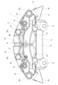
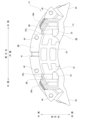
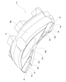
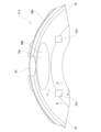
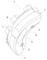
- FIG. 1 is a front view of a disc brake device according to a first embodiment, viewed from the outside in the axial direction.
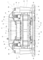
- FIG. 2 is a rear view of the disc brake device according to the first embodiment, viewed from the inner side in the axial direction.
- FIG. 3 is a plan view of the disc brake device according to the first embodiment as seen from the radially outer side.
- FIG. 4 is a bottom view of the disc brake device according to the first embodiment as seen from the radially inner side.
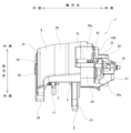
- FIG. 5 is a side view of the disc brake device according to the first embodiment as viewed from the right side of FIG. 1.
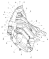
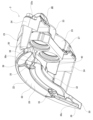
- FIG. FIG. 6 is a perspective view of the disc brake device according to the first embodiment, viewed from the axially outer side and the radially outer side.
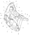
- FIG. 7 is a perspective view of the disc brake device according to the first embodiment as seen from the axially inner side and the radially outer side.
- FIG. 8 is a perspective view of the disc brake device according to the first embodiment, viewed from the axially outer side and the radially inner side.
- FIG. 9 is a perspective view of the disc brake device according to the first embodiment, viewed from the inner side in the axial direction and the inner side in the radial direction.
- FIG. 10 is a perspective view of the disc brake device according to the first embodiment with the caliper body taken out and viewed from the outside in the axial direction and the outside in the radial direction.
- FIG. 11 is a perspective view of the disc brake device according to the first embodiment, with the caliper body taken out and viewed from the axially inner side and the radially outer side.
- FIG. 12 is a perspective view of the disc brake device according to the first embodiment, with the caliper body taken out and viewed from the axially outer side and the radially inner side.
- FIG. 13 is a perspective view of a caliper body taken out from the disc brake device according to the first embodiment and viewed from the inner side in the axial direction and the inner side in the radial direction.
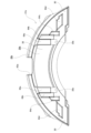
- FIG. 14 is a view of the outer body portion of the caliper body taken out from the disc brake device according to the first example of the embodiment and viewed from the outside in the axial direction.
- FIG. 15 is a view of the outer body portion of the caliper body taken out from the disc brake device according to the first example of the embodiment and viewed from the inner side in the axial direction.
- FIG. 16 is a view of the outer body portion of the caliper body and the outer pad taken out from the disc brake device according to the first example of the embodiment and viewed from the inner side in the axial direction.
- FIG. 17 is a view of the disk brake device according to the first embodiment, with the support and pad clips taken out and viewed from the outside in the axial direction.
- 18 is a view of the disc brake device according to the first embodiment, with the support and pad clip taken out, viewed from the right side of FIG. 1.
- FIG. 19 is a perspective view of the disc brake device according to the first embodiment, with the support and pad clips taken out and viewed from the outside in the axial direction and the outside in the radial direction.
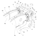
- FIG. 20 is a partial perspective view of the assembled state of the inner pad and the outer pad to the support, viewed from the axially inner side and the radially outer side, regarding the first example of the embodiment.
- FIG. 21 is a view, viewed from the axial inner side, of the mounting state of the pad clip and the return spring arranged on the axially outer side and on the outflow side with respect to the first embodiment.
- FIG. 20 is a partial perspective view of the assembled state of the inner pad and the outer pad to the support, viewed from the axially inner side and the radially outer side, regarding the first example of the embodiment.
- FIG. 21 is a view, viewed from the axial inner side, of the mounting state of the pad clip and the return spring arranged on the axially outer side and on the outflow side with respect to
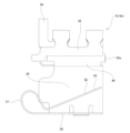
- FIG. 22 is a view of the disk brake device according to the first embodiment, with the pad clip arranged on the axially outer side and on the outflow side taken out and viewed from the circumferentially inner side.
- FIG. 23 is a view of the disk brake device according to the first embodiment, with the pad clip arranged on the axially outer side and on the outflow side taken out and viewed from the outer side in the circumferential direction.
- FIG. 24 is a view of the disk brake device according to the first embodiment, with the pad clip arranged on the axially outer side and on the outflow side taken out and viewed from the axially inner side.
- FIG. 25 is a diagram corresponding to FIG. 14, showing a second example of the embodiment.
- FIG. 26 is a diagram corresponding to FIG.
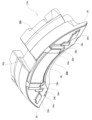
- FIG. 27 is a perspective view of the outer body portion of the caliper body taken out from the disc brake device according to the second example of the embodiment and viewed from the outside in the axial direction and the outside in the radial direction.
- FIG. 28 is a diagram corresponding to FIG. 14, showing a third example of the embodiment.
- FIG. 29 is a diagram corresponding to FIG. 15, showing a third example of the embodiment.
- FIG. 30 is a diagram corresponding to FIG. 27, showing the third example of the embodiment.
- FIG. 31 is a diagram corresponding to FIG. 14, showing a fourth example of the embodiment.
- FIG. 32 is a diagram corresponding to FIG. 15, showing a fourth example of the embodiment.
- FIG. 33 is a diagram corresponding to FIG.
- FIG. 34 is a diagram corresponding to FIG. 14, showing a fifth example of the embodiment.
- FIG. 35 is a diagram corresponding to FIG. 15, showing a fifth example of the embodiment.
- FIG. 36 is a diagram corresponding to FIG. 27, showing the fifth example of the embodiment.
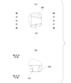
- 37A and 37B are diagrams showing a fifth example of the embodiment, in which FIG. 37A is a sectional view taken along the line AA of FIG. 34, and FIG. 37B is a sectional view taken along the line BB of FIG.
- FIG. 38 is a partial cross-sectional view showing a conventional floating type disc brake device.
- FIG. 1 A first example of the embodiment will be described with reference to FIGS. 1 to 24.
- FIG. 1 A first example of the embodiment will be described with reference to FIGS. 1 to 24.
- a disk brake device 1 of this example is a floating type disk brake device, and includes a support 2, a caliper body 3, an inner pad 4, an outer pad 5, and four pad clips 6a, 6b, 7a, 7b. .
- the support 2 is a casting made of a ferrous alloy such as cast iron, and is fixed to the vehicle body.
- the support 2 axially movably supports the caliper body 3 and axially movably supports the inner pad 4 and the outer pad 5 .
- the support 2 includes a pair of guide portions 9 arranged at both outer ends in the circumferential direction, and a rotor 8 (not shown in FIGS. 17 to 19, see FIG. 3).
- the rotor 8 has an inner side circumferential connecting portion 10 arranged axially inside the rotor 8 and extending in the circumferential direction, and an outer side circumferential connecting portion 11 arranged axially outside the rotor 8 and extending in the circumferential direction.
- the support 2 is fixed to a suspension system that constitutes the vehicle body using a pair of mounting holes 12 provided at both ends of the inner side circumferential connecting portion 10 in the circumferential direction. Note that the outer side circumferential connecting portion 11 can be omitted from the support 2 when implementing the present invention.
- Each of the pair of guide portions 9 has an inverted U shape when viewed in the circumferential direction, and is arranged so as to straddle the rotor 8 from the outside in the radial direction.
- Each of the pair of guide portions 9 includes an inner guide portion 13 for axially movably supporting the inner pad 4 and an outer guide portion 14 for axially movably supporting the outer pad 5.
- a caliper guide portion 15 is provided, which axially connects the radially outer ends of the inner guide portion 13 and the outer guide portion 14 .
- the inner guide portion 13 is arranged axially inward of the rotor 8 and extends radially. A radially inner end of the inner guide portion 13 is connected to a circumferentially outer end of the inner side circumferential connecting portion 10 .
- the inner guide portion 13 has an inner side guide groove 16 recessed outward in the circumferential direction on the radially inner portion of the inner side surface in the circumferential direction.
- the inner-side guide recessed groove 16 can be engaged with an ear portion 47a provided on the inner pad 4, which will be described later.
- the inner guide portion 13 has a protrusion (not shown) projecting inward in the circumferential direction at a radially intermediate portion of the inner side surface in the circumferential direction (outside the inner guide groove 16 in the radial direction).
- the outer guide portion 14 is arranged axially outside the rotor 8 and extends radially.
- a radially inner end portion of the outer guide portion 14 is connected to a circumferentially outer end portion of the outer side circumferential connecting portion 11 .
- the outer guide portion 14 has an outer guide recessed groove 17 recessed outward in the circumferential direction on the radially inner portion of the inner circumferential surface.
- the outer-side guide recessed groove 17 can be engaged with an ear portion 47b provided on the outer pad 5, which will be described later.
- the outer guide portion 14 has a protrusion 18 projecting inward in the circumferential direction at a radially intermediate portion of the inner circumferential surface (outside the outer guide groove 17 in the radial direction). As shown in FIG. 18 , the axial outer surface of the outer guide portion 14 protrudes axially outward beyond the axial outer surface of the outer-side circumferential connecting portion 11 .
- the caliper guide portion 15 is arranged radially outward of the rotor 8 and extends in the axial direction.
- a support hole 65 extending in the axial direction is formed inside the caliper guide portion 15 .
- the support hole 65 opens on the axially inner side surface of the caliper guide portion 15 .
- a front half of a slide pin 19 to be described later is slidably inserted into the support hole 65 .
- An axially inner end portion of the caliper guide portion 15 is arranged to protrude further inwardly in the axial direction than the inner guide portion 13 .
- the caliper body 3 is made of an aluminum-based alloy or an iron-based alloy and has a boat-like shape.
- the caliper body 3 is axially movably supported with respect to the support 2 using a pair of slide pins 19 .
- the caliper body 3 of this example has a split structure rather than an integral structure. That is, as shown in FIGS. 10 to 13, the caliper body 3 includes an inner body portion 20 and an outer body portion 21 which are constructed separately from each other. , 22b. In addition, when carrying out the present invention, the caliper body may be of an integral structure.
- the inner body portion 20 is arranged axially inward of the rotor 8 .
- the inner body portion 20 has a pair of cylinders 23 , a pair of circumferential arm portions 24 and a pair of radial projecting portions 25 .
- the number of cylinders provided in the inner body portion is not particularly limited, and may be one, or may be three or more.
- a pair of cylinders 23 are provided in the circumferentially intermediate portion of the inner body portion 20 .
- the pair of cylinders 23 are arranged side by side in the circumferential direction with their central axes parallel to the central axis of the rotor 8 .
- the cylinder 23 has a substantially cylindrical shape and opens only axially outward.
- a piston (not shown) is fitted inside the cylinder 23 so as to be axially movable.
- a pair of circumferential arm portions 24 are provided on both circumferentially outer portions of the inner body portion 20 .
- the pair of circumferential arm portions 24 are arranged on both outer sides of the pair of cylinders 23 in the circumferential direction.
- the circumferential arm portion 24 extends outward in the circumferential direction from the outer peripheral surface of the cylinder 23 .
- the circumferential arm portion 24 has an insertion hole for axially inserting the connecting member 22a at its circumferentially outer end (tip), and has a slide pin 19 at its circumferentially intermediate portion. It has a fixing hole 26 for fixing the proximal end.
- the circumferentially outer end of the circumferential arm 24 is offset axially outwardly relative to the circumferentially inner end or intermediate portion of the circumferential arm 24 . Therefore, the circumferential arm portion 24 has a substantially L shape when viewed in the radial direction.
- the axially outer surface of the circumferentially outer end of the circumferential arm portion 24 is a flat surface.
- the pair of radial projecting portions 25 are arranged in a circumferentially intermediate portion of the inner body portion 20 while being separated from each other in the circumferential direction.
- the pair of radial projecting portions 25 are arranged radially outward of the axially outer portions of the pair of cylinders 23 .
- the radial projecting portion 25 has a flat plate shape and extends radially outward from the outer peripheral surface of the cylinder 23 .
- the radial projecting portion 25 has an insertion hole for axially inserting the connecting member 22b.
- the axially outer surface of the radial projecting portion 25 is a flat surface and is positioned on the same imaginary plane as the axially outer surface of the circumferentially outer end portion of the circumferential arm portion 24 .
- the inner body portion 20 has belt-like ribs 27 extending in the circumferential direction on its axial inner surface.
- the belt-like ribs 27 cover the bottoms of the pair of cylinders 23 so as to traverse them in the circumferential direction.
- a circumferential intermediate portion of the band-shaped rib 27 is curved in a substantially arc shape so that the radially outer side is convex when viewed in the axial direction.
- Circumferentially outer ends of the strip-shaped rib 27 are arranged on both circumferentially outer sides of the inner body portion 20, and are arranged near the axially inner ends of the connecting members 22a arranged on the circumferentially outer side. It is
- the outer body portion 21 includes a substantially bow-shaped axial cover portion 28 arranged axially outside the outer pad 5 and a partially cylindrical radial cover portion 29 arranged radially outside the rotor 8 . have.
- the outer body portion 21 has a substantially L-shaped cross-sectional shape with respect to an imaginary plane including the central axis of the rotor 8 .
- the axial direction covering portion 28 and the radial direction covering portion 29 are configured integrally.
- the axial covering portion 28 is configured in a substantially arcuate flat plate shape, and directly presses the outer pad 5 in the axial direction during braking.
- the axial cover portion 28 is a portion that can be visually recognized from the outside when the disc brake device 1 is attached to the vehicle body, and the design surface is formed by the axial outer surface.
- the circumferential dimension of the axial covering portion 28 is made sufficiently larger than the outer body portion 112 of the conventional structure shown in FIG. Specifically, the circumferential dimension of the axial direction covering portion 28 is made larger than the circumferential dimension of the support 2 , and both circumferential direction outer portions of the axial direction covering portion 28 are arranged more circumferentially than the pair of guide portions 9 . It protrudes outward.
- the axial covering portion 28 covers the pair of guide portions 9 from the outside in the axial direction. In other words, the pair of guide portions 9 are made invisible from the outside.
- the circumferential dimension of the axial cover portion 28 by making the circumferential dimension of the axial cover portion 28 larger than the circumferential dimension of the support 2, the design surface formed by the axial outer surface of the axial cover portion 28 can be obtained. is largely ensured.
- the circumferential dimension of the axial direction covering portion 28 is larger than the circumferential dimension of each of the radial direction covering portion 29 and the inner body portion 20 .
- substantially triangular plate-shaped wing portions 30 are provided at both circumferentially outer ends of the axial direction covering portion 28 and project outwardly in the circumferential direction from the radial direction covering portion 29 and the inner body portion 20 .
- the axial covering portion 28 has a flat reference surface 31 on its axially inner side surface.
- the axial covering portion 28 has a protruding portion 32 protruding axially inward from the reference surface 31 at a circumferential intermediate portion of the axial inner surface.
- the projecting portion 32 is provided on substantially the entire portion of the axial inner surface of the axial cover portion 28 that axially faces a later-described substrate portion 46 b that constitutes the outer pad 5 . Therefore, the projecting portion 32 has a shape that substantially matches the substrate portion 46 b of the outer pad 5 .
- An axially inner side surface (tip surface) of the protruding portion 32 is provided with a contact convex portion 33 that protrudes axially inward.
- the contact protrusion 33 has a substantially lattice shape. The contact protrusion 33 contacts the axial outer surface (back surface) of the substrate portion 46b of the outer pad 5 during braking.
- the axial covering portion 28 has a pair of relief recesses 34 recessed axially outward from the reference surface 31 on both circumferentially outer portions of the overhanging portion 32 of the axial inner surface.
- the escape recess 34 is provided in a portion of the axial inner side surface of the axial cover portion 28 that axially faces the pair of outer guide portions 14 constituting the support 2 and the vicinity thereof.
- the relief recesses 34 are provided in a portion axially facing the outer guide portion 14 and a portion axially facing a portion located near the inner side of the outer guide portion 14 in the circumferential direction. .
- Each of the relief recesses 34 has a deep recess 34a on the inner side in the circumferential direction, and a shallow recess 34b having a shallower depth in the axial direction than the deep recess 34a on the outer side in the circumferential direction of the deep recess 34a.
- the axially outer portion of the outer guide portion 14 and The axially outer portions of the pad clips 7a and 7b attached to the circumferential inner surface of the outer guide portion 14 can enter.
- the axially outer portion of the outer guide portion 14 can be inserted into the shallow recess 34b, and the axially outer portions of the pad clips 7a and 7b can be inserted into the deep recess 34a. be able to. With such a configuration, interference between the pair of outer guide portions 14 and pad clips 7a and 7b and the outer body portion 21 is prevented.
- the pad clips 7a and 7b used in this example have a configuration in which the curled portion 57 protrudes greatly outward in the axial direction compared to the other portions of the pad clips 7a and 7b, as will be described later. Therefore, in this example, in order to prevent interference between the bottom surface of the deep recess 34a and the curled portion 57, the axial depth of the entire deep recessed portion 34a is not increased. A through hole 35 is formed to allow the insertion of the . This suppresses a decrease in rigidity of the outer body portion 21 compared to the case where the axial depth of the entire deep recess 34a is increased.
- a through hole 35 that is open only in the axial direction is formed in a portion of the axial cover portion 28 that axially faces the vicinity of each of the pair of outer guide portions 14 that constitute the support 2 . are doing. Specifically, the through-holes 35 are opened only in the axially outer side surface and the axially inner side surface of the axial cover portion 28, and are not opened in other portions (for example, the radial cover portion 29). In addition, the through hole 35 is formed in a portion of the axial cover portion 28 that axially faces the inner space of the outer side guide recessed groove 17 located near the inner side of the outer guide portion 14 in the circumferential direction. there is In this example, two through holes 35 are formed in the axial cover portion 28 .
- the axial inner opening of the through-hole 35 is positioned radially inward of the bottom surface of the deep recess 34a.
- the through-holes 35 can be processed, for example, by cutting (drilling) using a cutting tool such as a drill.
- the axially outer portion of the curled portion 57 which is the portion of the pad clips 7a, 7b that protrudes most axially outward, is inserted during braking.
- the through-hole 35 has a shape and size that allow the curled portion 57 to be inserted almost without a gap. Therefore, it is possible to suppress a decrease in rigidity of the caliper body 3 due to the formation of the through holes 35 .
- the central axis of the through hole 35 is arranged parallel to the central axis of the rotor 8 .
- the cross-sectional shape of the through hole 35 is constant along the axial direction.
- the through hole 35 has a substantially pentagonal or substantially trapezoidal cross-sectional shape (opening shape).
- the central axis of the through-hole can be inclined with respect to the central axis of the rotor, and the cross-sectional shape (opening shape) of the through-hole can be circular, elliptical, square, or other shape. It can also be shaped.
- the through hole 35 has a circumferential dimension slightly larger than a radial dimension. Therefore, even if the circumferential distance between the pair of pad clips 7a and 7b (curl portions 57) is changed by changing the circumferential dimension of the outer pad 5 to be used, the shape of the through hole 35 can be changed. can be used as is.
- one through-hole is provided to allow the portions to be inserted together. It is possible to form only one, or to form a plurality of through-holes into which the relevant portions can be inserted one by one.
- the relief recess is replaced by the shallow recess. can be omitted.
- the axial covering portion 28 has a first recessed groove 36 connected to the axially outer opening of the through hole 35 on its axially outer surface.
- Each of the first grooves 36 extends in the circumferential direction, and the inner end in the circumferential direction is connected to the outer opening in the axial direction of the through hole 35 .
- the axial cover 28 has two first grooves 36 .
- the first concave groove 36 corresponds to the concave groove described in the claims.
- the width dimension of the first recessed groove 36 is substantially constant over the entire length of the first recessed groove 36 and substantially the same as the radial dimension of the axially outer opening of the through-hole 35 .
- a first recessed groove 36 is provided so as to connect to the axially outer opening of the through hole 35 , and the width dimension of the first recessed groove 36 is set to the axially outer opening of the through hole 35 . It is assumed to be almost the same as the radial dimension in Therefore, the through hole 35 and the first concave groove 36 can be smoothly connected, and the axial outer opening of the through hole 35 can be made inconspicuous from the outside.
- designability can be enhanced by incorporating the axial outer opening of the through-hole 35 as part of the design of the design surface.
- Each of the first grooves 36 has a curved portion 36a curved in a substantially arc shape so that the radially outer side is convex on the inner side in the circumferential direction, and a linear straight portion 36b on the outer side in the circumferential direction. have.
- the linear portion 36 b extends radially inward as it goes circumferentially outward so as to follow the contour shape of the outer peripheral edge of the axial cover portion 28 .
- a circumferentially outer end portion of the first groove 36 (straight portion 36 b ) opens to a substantially straight radial inner surface corresponding to the chord of the axial covering portion 28 .
- the bottom surface 36c of the first concave groove 36 is not a flat surface but a convex curved surface curved in an arc. Specifically, the bottom surface 36c of the first recessed groove 36 is a convex curved surface curved in an arc shape so that the widthwise intermediate portion protrudes axially outward from the widthwise side portions.
- the axial covering portion 28 has a second recessed groove 37 on its axially outer surface, which connects the axially outer openings of the through holes 35 .
- the second groove 37 extends in the circumferential direction and is curved so that the radially outer side is convex.
- the width dimension of the second groove 37 is substantially constant over the entire length of the second groove 37 and substantially the same as the radial dimension of the axially outer opening of the through hole 35 . Therefore, the pair of first grooves 36 arranged on both outer sides in the circumferential direction are smoothly continuous in the circumferential direction via the pair of through holes 35 and the second grooves 37 .
- the axial covering portion 28 has an annular fan-shaped display portion 38 that can be used to display a logo or the like on the circumferentially intermediate portion of the axial outer surface.
- the display portion 38 has a flat surface and is arranged radially outward of the pair of through holes 35 and the second groove 37 .
- the circumferential dimension of the axial covering portion 28 is larger than the circumferential dimension of the support 2, the circumferential dimension of the display portion 38 can also be sufficiently increased. Since the display portion 38 is surrounded by the groove portions 39 on both the outer sides in the circumferential direction and the outer side in the radial direction, the display portion 38 is visually recognized as floating outward in the axial direction.
- the radial covering portion 29 has a partially cylindrical shape and extends axially inward from the outer peripheral edge portion of the axial covering portion 28 .
- the radial direction covering portion 29 covers the pair of guide portions 9 constituting the support 2, a portion of the rotor 8 in the circumferential direction, and both the inner and outer pads 4 and 5 from the radial outside.
- the circumferential dimension of the radial cover portion 29 is the same as the circumferential dimension of the inner body portion 20 .
- the radial covering portion 29 has mounting holes (screw holes) 40 for fixing the distal end portions of the connecting members 22a and 22b at a plurality of locations (four locations in the illustrated example) in the circumferential direction.
- the plurality of mounting holes 40 are arranged at the same pitch in the circumferential direction as the plurality of insertion holes provided in the inner body portion 20 .
- the mounting hole 40 opens to the axial inner surface of the radial cover portion 29 .
- the radial direction covering portion 29 has a central window 41 which is open on both sides in the radial direction on the inner side in the axial direction of the central portion in the circumferential direction.
- the central window 41 has an axially elongated slit shape.
- the central window 41 also opens to the axial inner surface of the radial cover portion 29 .
- the central window 41 can be used to visually confirm the state of wear of the inner pad 4 and the outer pad 5 .
- the outer body portion 21 consisting of the axial cover portion 28 and the radial cover portion 29 is fixed to the axially outer side of the inner body portion 20 using connecting members 22a and 22b, respectively, which are bolts.
- the distal end portion of the connecting member 22a axially inserted through the insertion hole provided in the circumferential arm portion 24 of the inner body portion 20 is attached to the radially outer portion of the radial covering portion 29 of the outer body portion 21.
- the distal end portion of the connecting member 22b screwed into the provided mounting hole 40 and axially inserted through the insertion hole provided in the radial projecting portion 25 of the inner body portion 20 is inserted into the outer body portion 21 in the radial direction. It is screwed into a mounting hole 40 provided on the circumferentially inner side of the cover portion 29 .
- the outer body portion 21 is connected to the axially outer side of the inner body portion 20 using the connecting members 22a and 22b.
- a pair of openings 42 are formed between the axially outer side surface of the inner body section 20 and the axially inner side surface of the outer body section 21 while the inner body section 20 and the outer body section 21 are connected.
- the pair of openings 42 are separated from each other in the circumferential direction and arranged on both circumferentially outer sides of the pair of radial projections 25 .
- Each of the openings 42 has a substantially rectangular shape when viewed in the radial direction.
- the caliper body 3 is supported by the support 2 so as to be movable in the axial direction.
- the proximal end portion of the slide pin 19 is fixed to the fixing hole 26 provided in the circumferential intermediate portion of the circumferential arm portion 24 that constitutes the inner body portion 20, and the front half portion of the slide pin 19 is It is inserted inside a support hole 65 formed in the caliper guide portion 15 constituting the support 2 so as to allow relative displacement (sliding) in the axial direction.
- a boot 43 covers a portion of the outer peripheral surface of the slide pin 19 located between the support hole 65 and the fixing hole 26 .
- the inner pad 4 includes a lining 44a and a back plate 45a, and is supported between the pair of inner guide portions 13 constituting the support 2 so as to be movable in the axial direction. It is
- the back plate 45a has a rectangular plate-shaped base portion 46a that supports the back surface (axial inner side surface) of the lining 44a, and convex ear portions 47a that protrude outward from the base portion 46a in the circumferential direction. are doing.
- the substrate portion 46a has a shape that substantially matches the lining 44a.
- the ears 47 a forming the inner pad 4 are inserted into the inner guide grooves 16 provided in the inner guide portions 13 . are engaged with each other.
- the outer pad 5 includes a lining 44b and a back plate 45b, and is supported between the pair of outer guide portions 14 forming the support 2 so as to be movable in the axial direction.
- the back plate 45b has a rectangular plate-shaped base portion 46b that supports the back surface of the lining 44b, and convex ear portions 47b that protrude outward from the base portion 46b in the circumferential direction.
- the substrate portion 46b has a shape that substantially matches the lining 44b.
- the ear portions 47 b forming the outer pad 5 are aligned with the outer side guide grooves 17 provided in the outer guide portions 14 . are engaged with each other.
- Pad clips 6a and 6b are interposed between the circumferentially outer side surfaces of the back plate 45a constituting the inner pad 4 and the circumferentially inner side surfaces of the pair of inner guide portions 13, respectively.
- pad clips 7a and 7b are interposed between the circumferentially outer side surfaces of the back plate 45b constituting the outer pad 5 and the circumferentially inner side surfaces of the pair of outer guide portions 14, respectively. This enables smooth axial movement of the inner pad 4 and the outer pad 5 .
- the pad clips 7a and 7b arranged on the outer side in the axial direction correspond to the pad clips described in the claims.
- each of the pad clips 6a, 6b, 7a, and 7b includes a return clip that biases the inner pad 4 and the outer pad 5 away from the rotor 8 when the braking force is released.
- a spring 48 is mounted.
- a pair of arranged pad clips 6b and 7b have shapes symmetrical with respect to the axial direction.
- the pair of pad clips 6a and 6b arranged to face each other in the circumferential direction and the pair of pad clips 7a and 7b arranged to face each other in the circumferential direction each have a symmetrical shape with respect to the circumferential direction. ing.
- the pad clip 7b is made by pressing an elastic and corrosion-resistant metal plate such as a stainless steel plate.
- a directional pressing portion 51 , a circumferential pressing portion 52 , a spring holding portion 53 , and a restraining portion 54 are provided.
- the holding portion 49 is configured in a substantially rectangular U-shaped cross section, and is provided in the radially intermediate portion of the pad clip 7b.
- the holding portion 49 elastically holds the projection portion 18 provided on the inner side surface in the circumferential direction of the outer guide portion 14 from both sides in the radial direction, thereby positioning the pad clip 7b in the radial direction.
- a pair of claw pieces 55a and 55b bent outward in the circumferential direction are provided at both ends of the holding portion 49 in the axial direction.
- the pair of claw pieces 55a and 55b elastically sandwich the protrusion 18 from both sides in the axial direction to position the pad clip 7b in the axial direction.
- the guide plate portion 50 is configured in a flat plate shape and provided on the radially inner portion of the pad clip 7b.
- the guide plate portion 50 is arranged along the bottom surface (inner side surface in the circumferential direction) of the outer side guide groove 17 . It is arranged (held) between the bottom surface of the outer side guide groove 17 and the tip end surface (circumferential outer surface) of the ear portion 47b of the outer pad 5 .
- the radial pressing portion 51 is configured in a horizontal V shape and provided at the radially inner end portion of the pad clip 7b.
- the radial pressing portion 51 is composed of a flat plate-like pressing substrate portion 56 that is bent inward in the circumferential direction from the radially inner end portion of the guide plate portion 50 at a substantially right angle, and a pressing substrate portion 56 that extends radially from the axially outer end portion of the pressing substrate portion 56 .
- a substantially cylindrical curled portion 57 that is folded back 180 degrees outward and axially inward (toward the rotor 8 side), and in a free state, extends radially outward from the curled portion 57 toward the axially inner side.
- a flat pressing body portion 58 is provided.
- the pressing main body portion 58 is arranged radially inside the ear portion 47b when the ear portion 47b constituting the outer pad 5 is engaged with the outer side guide concave groove 17 in an uneven manner. Then, based on the bending deformation of the curled portion 57, the ear portion 47b is pressed radially outward.
- the circumferential pressing portion 52 is configured in an inverted U shape and provided on the radially outer portion of the pad clip 7b.
- the circumferential pressing portion 52 is flexurally deformed so that the circumferentially outer surface of the radially outer portion of the back plate 45b constituting the outer pad 5 (the portion radially outer than the ear portion 47b) is moved to the circumferentially inner side (outlet portion). side).
- the spring holding portion 53 is configured in the shape of a tongue and is provided on the radially outer portion of the pad clip 7b.
- the spring holding portion 53 is provided so as to extend outward in the circumferential direction from the holding portion 49 and has a function of holding the return spring 48 .
- the restraining portion 54 is configured in an inverted J shape and provided at the radially outer end portion of the pad clip 7b.
- the restraining portion 54 is provided so as to be continuous with the circumferential pressing portion 52, so that the return spring 48 can be attached to the pad clip 7b (the combination of the pad clip 7b and the return spring 48) before the outer pad 5 is assembled. It is provided to support the elastic force (returning force) of the return spring 48 and restrain the return spring 48 .
- the axially outer portion of the pad clip 7b (the axially outer portion of the guide plate portion 50, the curl portion 57, the restraining portion 54) ) are arranged to project axially outward from the outer guide portion 14 .
- the curled portion 57 protrudes outwardly in the axial direction to a greater extent than the other portions of the pad clip 7b, and is arranged to protrude most outwardly in the axial direction from the outer guide portion 14. As shown in FIG.
- the curled portion 57 constituting the pad clip 7b is pulled from the outer body during braking. Interference with the axial cover portion 28 constituting the portion 21 is likely to occur.
- a through hole 35 is provided in a portion of the axial covering portion 28 that axially faces the inner space of the outer guide groove 17 , and the curled portion 57 is inserted into the through hole 35 . Therefore, interference between the curled portion 57 and the axial cover portion 28 can be prevented.
- a return spring 48 is attached to the pad clip 7b (6a, 6b, 7a) of this example.
- the return spring 48 is, for example, a torsion coil spring formed by bending a wire rod made of spring steel such as stainless steel or piano wire.
- a stop arm 60 and a spring arm 61 are provided.
- the coil portion 59 is held by the spring holding portion 53 of the pad clip 7b with the central axis directed in the circumferential direction.
- the locking arm portion 60 is arranged axially inside (toward the rotor 8 ) of the coil portion 59 , and the tip thereof is locked to the circumferential pressing portion 52 .
- the spring arm portion 61 is arranged axially outside (on the side opposite to the rotor 8) of the coil portion 59, and is configured in a substantially rectangular U shape when viewed in the circumferential direction.
- the tip portion of the spring arm portion 61 abuts against the axially inner side surface of the ear portion 47b of the outer pad 5 and presses the outer pad 5 axially outward (toward the side opposite to the rotor 8).
- the majority of the return spring 48 is arranged outside (back side) of the pad clip 7b in the circumferential direction. It is configured so that it does not protrude greatly not only in the direction but also in the axial and radial directions.
- the outer pad 5 is pressed against the axial outer surface of the rotor 8 .
- the rotor 8 is strongly clamped from both sides in the axial direction by the inner pad 4 and the outer pad 5, and braking is performed.
- the outer guide portion 14 of the support 2 and the outer guide portion Interference between the pad clips 7a and 7b attached to the caliper body 3 and the axial cover portion 28 of the caliper body 3 can be prevented.
- the circumferential dimension of the axial direction covering portion 28 is made larger than the circumferential dimension of the support 2 so that the shaft
- the direction covering portion 28 covers the pair of guide portions 9 from the outside in the axial direction.
- the pad clips 7a and 7b are attached to the inner side surfaces of the pair of outer guide portions 14 in the circumferential direction, and the curled portions 57 of the pad clips 7a and 7b are axially outward of the outer guide portions 14. It is placed in a prominent position.
- the curled portion 57 and the axial cover portion 28 are likely to interfere with each other during braking. Therefore, in this example, the through hole 35 is formed in a portion of the axial covering portion 28 that axially faces the inner space of the outer guide groove 17 , so that the curled portion 57 is positioned inside the through hole 35 . I am trying to insert it. Therefore, interference between the curled portion 57 and the axial cover portion 28 can be prevented.
- the through-holes 35 are opened only in the axially outer side surface and the axially inner side surface of the axial cover portion 28, and are not opened in other portions (for example, the radial cover portion 29). Therefore, a decrease in rigidity of the caliper body 3 due to the formation of the through holes 35 can be suppressed.
- the through-holes 35 through the through-holes 35, the heat of the engaging portion between the ear portion 47b of the outer pad 5 and the outer side guide groove 17 can be released, and the engaging portion can be cooled. Furthermore, by forming the through holes 35, the weight of the caliper body 3 can be reduced.
- relief recesses 34 are formed in portions of the axial inner surface of the axial direction covering portion 28 that axially face the outer guide portion 14 and its vicinity.
- the axially outer portion of the outer guide portion 14 the axially outer portions of the pad clips 7a and 7b (the axially outer portion of the guide plate portion 50, the restraint portion 54), and the axially outer portion of the return spring 48 (spring arm It is also possible to prevent interference between the axial outer portion of the portion 61 and the axial cover portion 28 .
- a first groove 36 is provided on the axially outer surface of the axial covering portion 28 so as to connect to the axially outer opening of the through hole 35, and the width of the first groove 36 is set to , the radial dimension of the axially outer opening of the through hole 35 is substantially the same, so that the through hole 35 and the first groove 36 are smoothly connected to form the axially outer opening of the through hole 35. can be made inconspicuous from the outside.
- designability can be enhanced by incorporating the axial outer opening of the through-hole 35 as part of the design of the design surface.
- FIG. 25 A second example of the embodiment will be described with reference to FIGS. 25 to 27.
- FIG. 25 A second example of the embodiment will be described with reference to FIGS. 25 to 27.
- a through hole 35a having a cross-sectional shape that changes according to the position in the axial direction is formed in the axial cover portion 28a that constitutes the outer body portion 21a.
- the through-hole 35a of this example has a circumferentially inner inner surface forming an inner surface that is inclined in a circumferentially inner direction toward the axially outer side.
- the cross-sectional area (opening area) of the through-hole 35a increases toward the outside in the axial direction.
- the through hole 35a has an axially inner opening that is substantially diamond-shaped, while an axially outer opening that is substantially trapezoidal or substantially parallelogram-shaped.
- the axial covering portion 28a has, on its axial outer surface, a second groove 37a that connects the axially outer openings of the pair of through holes 35a in the circumferential direction. There is no first groove extending circumferentially outward from the axially outer opening.
- the axial covering portion 28a has a pair of design recesses 62 recessed axially inward on both circumferentially outer portions of the axially outer side surface.
- Each of the design recesses 62 has a substantially fan shape.
- the axial covering portion 28a has relief recesses 34, each of which is a deep recess 34a, on both circumferentially outer sides of the projecting portion 32 on the axial inner surface. Wear of the inner pad 4 and the outer pad 5 progresses inside the relief recess 34, and when the caliper body 3 moves axially inward with respect to the support 2, the axially outer portions of the pad clips 7a and 7b enter. do. That is, in the case of this example, even if the shallow recessed portion is omitted from the axially inner side surface of the axial direction covering portion 28a, the inner pad 4 and the outer pad 5 are fully worn, and the outer guide portion 14 remains axially outside. Interference between the side surface and the axial inner surface (reference surface 31) of the axial covering portion 28a can be prevented.
- the radial covering portion 29a that constitutes the outer body portion 21a does not have central windows that are open on both sides in the radial direction at the circumferential central portion of the outer peripheral surface, and has a concavely curved central portion that is recessed radially inward. It has a recess 63 .
- the inner side surface on the inner side in the circumferential direction which constitutes the inner surface of the through hole 35a, is inclined in the direction toward the inner side in the circumferential direction toward the outer side in the axial direction.
- the continuity with the second concave groove 37a can be improved, and the design can be improved.
- Other configurations and effects are the same as those of the first embodiment.
- FIG. 28 to 30 A third example of the embodiment will be described with reference to FIGS. 28 to 30.
- FIG. 28 to 30 A third example of the embodiment will be described with reference to FIGS. 28 to 30.
- a through hole 35b having a constant cross-sectional shape along the axial direction is formed in the axial cover portion 28b that constitutes the outer body portion 21b.
- the through hole 35b is a rectangular hole having a rectangular (substantially square) cross-sectional shape.
- the axial covering portion 28b has neither the first grooves nor the second grooves connected to the axially outer openings of the pair of through holes 35b on the axially outer side surface.
- the axial cover portion 28b has a plurality of (four in the illustrated example) each of design convex portions 64a to 64d on both outer sides in the circumferential direction with the display portion 38 interposed therebetween.
- the axial outer side surfaces (end surfaces) of the design convex portions 64a to 64d are flat surfaces, and are arranged on the same imaginary plane as the display portion .
- An axially outer opening of the through-hole 35b is surrounded by a display portion 38 and a plurality of design projections 64a to 64c.
- Each of the designed protrusions 64a to 64d has a substantially rectangular shape.
- the radial covering portion 29b that constitutes the outer body portion 21b does not have central windows that are open on both sides in the radial direction at the circumferential center portion of the outer peripheral surface, and has a rectangular concave central concave portion that is concave radially inward. 63a.
- FIG. 31 A fourth example of the embodiment will be described with reference to FIGS. 31 to 33.
- FIG. 31 A fourth example of the embodiment will be described with reference to FIGS. 31 to 33.
- the axial covering portion 28c forming the outer body portion 21c has a rectangular through hole 35b having a rectangular (substantially square) cross-sectional shape, like the structure of the third example of the embodiment.
- the axial covering portion 28c has a pair of first recessed grooves 36 on its axially outer surface, which are connected to the axially outer openings of the pair of through holes 35b.
- the first groove 36 consists of only a linear portion 36b linearly extending in the circumferential direction, and is formed so as to cross the through hole 35b in the circumferential direction.
- a circumferentially outer end of the first groove 36 (straight line portion 36b) opens to a cylindrical radially outer surface (outer peripheral surface) corresponding to the arc of the axial covering portion 28c.
- the circumferentially inner end portion of the first groove 36 (straight portion 36b) reaches the vicinity of the circumferentially central portion of the axially outer surface of the axially covering portion 28c.
- Circumferentially inner ends of the pair of first grooves 36 are not connected to each other and are spaced apart in the circumferential direction.
- a circumferentially inner portion of the first groove 36 has a tapered shape in which the width dimension decreases toward the circumferentially inner side.
- the bottom surface 36c of the first concave groove 36 is not a flat surface but a concave curved surface curved in an arc. Specifically, the bottom surface 36c of the first recessed groove 36 is a concave curved surface curved in an arc shape so that the widthwise intermediate portion is recessed axially inward from the widthwise side portions.
- the axial covering portion 28c has an elliptical display portion 38a that can be used to display a logo or the like on the radially outer portion of the circumferentially intermediate portion of the axially outer surface.
- the axial covering portion 28c has relief recesses 34 each formed of a deep recess 34a on both circumferentially outer sides of the projecting portion 32 of the axial inner surface. have. Wear of the inner pad 4 and the outer pad 5 progresses inside the relief recess 34, and when the caliper body 3 moves axially inward with respect to the support 2, the axially outer portions of the pad clips 7a and 7b enter. do.
- the radial direction cover portion 29a that constitutes the outer body portion 21c has a central concave portion 63 that is recessed radially inward in the circumferential direction central portion of the outer peripheral surface.
- the axial covering portion 28c has the linear first concave groove 36 so as to circumferentially cross the axially outer opening of the through hole 35b.
- the axially outer opening of the through hole 35b can be made inconspicuous from the outside.
- Other configurations and effects are the same as those of the first and second examples of the embodiment.
- a through hole 35d whose cross-sectional shape changes according to the position in the axial direction is formed in the axial cover portion 28d that constitutes the outer body portion 21d.
- the through hole 35d is a tapered rectangular hole, and the cross-sectional area decreases toward the outside in the axial direction. This reduces the axially outer opening of the through hole 35d.
- the central axis of the through hole can also be inclined with respect to the central axis of the rotor.
- the axial covering portion 28d has neither the first concave groove nor the second concave groove connected to the axially outer openings of the pair of through holes 35d on the axial outer side surface.
- the axial covering portion 28d has an elliptical display portion 38a that can be used to display a logo or the like on the radially outer portion of the circumferentially intermediate portion of the axially outer surface.
- the axial covering portion 28d does not have relief recesses on both circumferentially outer portions of the projecting portion 32 of the axial inner surface. That is, in the case of this example, even if the escape recesses are omitted from the axial inner side surface of the axial direction cover portion 28d, the inner pad 4 and the outer pad 5 are fully worn, and the outer guide portion 14 remains axially outside. It is possible to prevent interference between the side surface and the axial inner side surface (reference surface 31) of the axial cover portion 28d, and to prevent the portion of the pad clips 7a and 7b other than the curled portion 57 and the axial direction of the axial cover portion 28d. Interference with the inner surface (reference surface 31) can be prevented.
- the radial direction cover portion 29a that constitutes the outer body portion 21d has a central concave portion 63 that is recessed radially inward in the circumferential direction central portion of the outer peripheral surface.
- the through hole 35d is a tapered rectangular hole whose cross-sectional area decreases toward the outer side in the axial direction, elastic deformation occurs in the axial cover portion 28d during braking. Also in this case, interference between the through hole 35d and the curled portion 57 can be suppressed. In addition, since the axially outer opening of the through hole 35d can be made smaller, the opening can be made inconspicuous from the outside. Other configurations and effects are the same as those of the first embodiment.
- a configuration is adopted in which a pad clip is attached to an outer guide portion that constitutes a support, and a curled portion that constitutes the pad clip protrudes most outward in the axial direction from the outer guide portion. Because of the arrangement, a through-hole into which the curled portion can be inserted is formed in the axial cover portion that constitutes the caliper body.
- the portion to be inserted into the through-hole formed in the axial cover portion is not limited to the curled portion, but the portion of the pad clip that is arranged on the outermost side in the axial direction. be able to. Therefore, the formation position and size of the through hole can be changed according to the shape of the pad clip to be used.
- part or all of the outer guide portion can be inserted into the through hole formed in the axial cover portion.
- the formation position and size of the through hole can be changed according to the shape of the outer guide portion.
- the support (2) has an inner guide portion (13) which axially movably supports the inner pad (4) and an axially movable outer pad (5) which are provided on both circumferentially outer sides of the support (2).
- the caliper body (3) has an inner body portion (20) which has a cylinder (23) and is arranged axially inside the rotor (8), and presses the outer pad (5) during braking. an outer body portion (21, 21a, 21b, 21c, 21d),
- the outer body portion (21) has through holes (35, 35a) opened only in the axial direction in at least one of the outer guide portion (14) and portions axially facing the vicinity of the outer guide portion (14). , 35b, 35d), A floating type disc brake device (1).
- the floating type disc brake device (1) according to any one of [1] to [3] above,
- the outer pad (5) has a convex ear (47b) projecting in the circumferential direction
- the outer guide portion (14) has a guide groove (outer side guide groove 17) that can be engaged with the ear portion (47b)
- the through hole (35) is provided in a portion axially facing the inner space of the guide groove (outer side guide groove 17), A floating type disc brake device (1).
- a floating type disc brake device (1) according to any one of [1] to [4] above, A floating type disc brake device (1), wherein the through hole (35) has a circumferential dimension larger than a radial dimension.
- the floating type disc brake device (1) according to [10] above, The outer body portion (21) has a substantially arcuate shape when viewed in the axial direction, The groove (first groove 36) is open to the radially inner side surface or the radially outer side surface of the outer body portion (21). A floating type disc brake device (1).
- the floating type disc brake device (1) according to any one of [9] to [11] above, The bottom surface (36c) of the concave groove (first concave groove 36) is a convex curved surface curved in an arc so that the widthwise intermediate portion protrudes axially outward from the widthwise both side portions.
- a disc brake device (1) is a convex curved surface curved in an arc so that the widthwise intermediate portion protrudes axially outward from the widthwise both side portions.
- the floating type disc brake device (1) according to any one of [9] to [11] above,
- the bottom surface (36c) of the concave groove (first concave groove 36) is a concave curved surface curved in an arc shape so that the widthwise middle portion is concave inward in the axial direction with respect to the widthwise both side portions.
- [14] The floating type disc brake device (1) according to any one of [1] to [13] above, A floating type disc brake device (1), wherein the central axis of the through-hole (35) and the central axis of the rotor (8) are parallel to each other.
- [15] The floating type disc brake device (1) according to any one of [1] to [14] above, A floating type disc brake device (1), wherein the outer body portion (21) has two of the through holes (35).
- the disc brake device of the present invention it is possible to realize a disc brake device that can prevent interference between the outer guide portion of the support and the pad clip attached to at least one of the outer guide portion and the outer body portion of the caliper body.
- Reference Signs List 1 disc brake device 2 support 3 caliper body 4 inner pad 5 outer pad 6a, 6b pad clip 7a, 7b pad clip 8 rotor 9 guide portion 10 inner side circumferential connecting portion 11 outer side circumferential connecting portion 12 mounting hole 13 inner guide portion 14 outer guide portion 15 caliper guide portion 16 inner guide groove 17 outer guide groove 18 protrusion 19 slide pin 20 inner body portion 21, 21a, 21b, 21c, 21d outer body portion 22a, 22b connecting member 23 cylinder 24 circumference Directional arm portion 25 Radial overhanging portion 26 Fixing hole 27 Belt-shaped rib 28, 28a, 28b, 28c, 28d Axial covering portion 29, 29a, 29b Radial covering portion 30 Wing portion 31 Reference surface 32 Overhanging portion 33 Contact Projection 34 Escape recess 34a Deep recess 34b Shallow recess 35, 35a, 35b, 35d Through hole 36 First recess 36a Curved portion 36b Straight portion 36c Bottom surface 37 Second recess 38, 38a Display 39 Groove 40 Mounting hole 41 central
Landscapes
- Engineering & Computer Science (AREA)
- General Engineering & Computer Science (AREA)
- Mechanical Engineering (AREA)
- Braking Arrangements (AREA)
Abstract
Description
前記インナパッドは、ロータの軸方向内側に配置されている。
前記アウタパッドは、前記ロータの軸方向外側に配置されている。
前記サポートは、車体に固定され、前記インナパッド及び前記アウタパッドのそれぞれを軸方向に移動可能に支持する。
前記キャリパボディは、前記サポートに対して軸方向に関する移動を可能に支持されている。
前記サポートは、周方向両外側部のそれぞれに、前記インナパッドを軸方向に移動可能に支持するインナガイド部と、前記アウタパッドを軸方向に移動可能に支持するアウタガイド部とを有している。
前記キャリパボディは、シリンダを有し、かつ、前記ロータよりも軸方向内側に配置されたインナボディ部と、制動時に前記アウタパッドを押圧するアウタボディ部とを有している。
前記アウタボディ部は、前記アウタガイド部及び前記アウタガイド部の近傍部分と軸方向に対向する部分の少なくとも一方に、軸方向にのみ開口した貫通孔を有している。
前記貫通孔の内側には、前記パッドクリップのうちで軸方向外側に最も突出した部分を挿入することができる。
この場合には、貫通孔の開口形状(断面形状)を、たとえば、矩形(正方形を含む)、台形、五角形、平行四辺形などにすることができる。
実施の形態の第1例について、図1~図24を用いて説明する。
本例のディスクブレーキ装置1は、フローティング型のディスクブレーキ装置であり、サポート2と、キャリパボディ3と、インナパッド4と、アウタパッド5と、4つのパッドクリップ6a、6b、7a、7bとを備える。
サポート2は、鋳鉄などの鉄系合金製の鋳造品であり、車体に固定される。サポート2は、キャリパボディ3を軸方向に移動可能に支持するとともに、インナパッド4及びアウタパッド5のそれぞれを軸方向に移動可能に支持する。
キャリパボディ3は、アルミニウム系合金製又は鉄系合金製であり、舟型形状を有している。キャリパボディ3は、1対のスライドピン19を利用して、サポート2に対し軸方向に移動可能に支持されている。
インナボディ部20は、ロータ8よりも軸方向内側に配置されている。インナボディ部20は、1対のシリンダ23と、1対の周方向腕部24と、1対の径方向張出部25とを有している。なお、本発明を実施する場合に、インナボディ部に設けるシリンダの数は、特に限定されず、1つだけ設けても良いし、3つ以上設けても良い。
アウタボディ部21は、アウタパッド5よりも軸方向外側に配置された、略弓形状の軸方向覆い部28と、ロータ8の径方向外側に配置された、部分円筒形状の径方向覆い部29とを有している。アウタボディ部21は、ロータ8の中心軸を含む仮想平面に関して、略L字形の断面形状を有している。軸方向覆い部28と径方向覆い部29とは、一体に構成されている。
図20に示すように、インナパッド4は、ライニング44aと、裏板45aとを備えており、サポート2を構成する1対のインナガイド部13同士の間に、軸方向に関する移動を可能に支持されている。
インナパッド4を構成する裏板45aの周方向両外側面と1対のインナガイド部13のそれぞれの周方向内側面との間に、パッドクリップ6a、6bを介在させている。加えて、アウタパッド5を構成する裏板45bの周方向両外側面と1対のアウタガイド部14のそれぞれの周方向内側面との間に、パッドクリップ7a、7bを介在させている。これにより、インナパッド4及びアウタパッド5の円滑な軸方向移動を可能としている。なお、軸方向外側に配置されたパッドクリップ7a、7bが、特許請求の範囲に記載したパッドクリップに相当する。
本例のパッドクリップ7b(6a、6b、7a)には、戻しばね48が装着される。
本例のディスクブレーキ装置1により制動を行うには、キャリパボディ3のシリンダ23にマスタシリンダから圧油を送り込む。これにより、図示しないピストンを軸方向外側に向けて押し出す。そして、ピストンによりインナパッド4を、ロータ8の軸方向内側面に押し付け、キャリパボディ3をサポート2に対して軸方向内側に移動させる。これにより、キャリパボディ3を構成する軸方向覆い部28に備えられた張出部32の当接凸部33を、アウタパッド5を構成する裏板45bの裏面に押し付ける。これにより、アウタパッド5をロータ8の軸方向外側面に押し付ける。この結果、ロータ8が、インナパッド4及びアウタパッド5により軸方向両側から強く挟持されて制動が行われる。
実施の形態の第2例について、図25~図27を用いて説明する。
その他の構成及び作用効果については、実施の形態の第1例と同じである。
実施の形態の第3例について、図28~図30を用いて説明する。
その他の構成及び作用効果については、実施の形態の第1例と同じである。
実施の形態の第4例について、図31~図33を用いて説明する。
その他の構成及び作用効果については、実施の形態の第1例及び第2例と同じである。
実施の形態の第5例について、図34~図37を用いて説明する。
その他の構成及び作用効果については、実施の形態の第1例と同じである。
[1]
ロータ(8)の軸方向内側に配置されたインナパッド(4)と、
前記ロータ(8)の軸方向外側に配置されたアウタパッド(5)と、
車体に固定され、前記インナパッド(4)及び前記アウタパッド(5)のそれぞれを軸方向に移動可能に支持するサポート(2)と、
前記サポート(2)に対して軸方向に関する移動を可能に支持されたキャリパボディ(3)と、を備え、
前記サポート(2)は、周方向両外側部のそれぞれに、前記インナパッド(4)を軸方向に移動可能に支持するインナガイド部(13)と、前記アウタパッド(5)を軸方向に移動可能に支持するアウタガイド部(14)とを有し、
前記キャリパボディ(3)は、シリンダ(23)を有し、かつ、前記ロータ(8)よりも軸方向内側に配置されたインナボディ部(20)と、制動時に前記アウタパッド(5)を押圧するアウタボディ部(21、21a、21b、21c、21d)とを有し、
前記アウタボディ部(21)は、前記アウタガイド部(14)及び前記アウタガイド部(14)の近傍部分と軸方向に対向する部分の少なくとも一方に、軸方向にのみ開口した貫通孔(35、35a、35b、35d)を有する、
フローティング型ディスクブレーキ装置(1)。
[2]
上記[1]に記載のフローティング型ディスクブレーキ装置(1)であって、
前記アウタパッド(5)と前記アウタガイド部(14)との間に配置された、パッドクリップ(7a、7b)をさらに備え、
前記パッドクリップ(7a、7b)の一部が前記貫通孔(35等)の内側に挿入される、
フローティング型ディスクブレーキ装置(1)。
[3]
上記[2]に記載のフローティング型ディスクブレーキ装置(1)であって、
前記貫通孔(35)は、前記パッドクリップ(7a、7b)の一部がほぼ隙間なく挿入可能な形状及び大きさを有する、フローティング型ディスクブレーキ装置(1)。
[4]
上記[1]~[3]のうちのいずれか1つに記載のフローティング型ディスクブレーキ装置(1)であって、
前記アウタパッド(5)は、周方向に突出した凸状の耳部(47b)を有しており、
前記アウタガイド部(14)は、前記耳部(47b)と係合可能なガイド凹溝(アウタ側ガイド凹溝17)を有しており、
前記貫通孔(35)は、前記ガイド凹溝(アウタ側ガイド凹溝17)の内部空間と軸方向に対向する部分に備えられている、
フローティング型ディスクブレーキ装置(1)。
[5]
上記[1]~[4]のうちのいずれか1つに記載のフローティング型ディスクブレーキ装置(1)であって、
前記貫通孔(35)は、径方向寸法よりも周方向寸法が大きい、フローティング型ディスクブレーキ装置(1)。
[6]
上記[1]~[5]のうちのいずれか1つに記載のフローティング型ディスクブレーキ装置(1)であって、
前記貫通孔(35、35b)は、軸方向視で略多角形の開口形状を有する、フローティング型ディスクブレーキ装置(1)。
[7]
上記[1]~[6]のうちのいずれか1つに記載のフローティング型ディスクブレーキ装置(1)であって、
前記貫通孔(35a、35d)の断面形状は、軸方向位置に応じて変化する、フローティング型ディスクブレーキ装置(1)。
[8]
上記[1]~[7]のうちのいずれか1つに記載のフローティング型ディスクブレーキ装置(1)であって、
前記アウタボディ部(21)の周方向寸法は、前記サポート(2)の周方向寸法よりも大きい、フローティング型ディスクブレーキ装置(1)。
[9]
上記[1]~[8]のうちのいずれか1つに記載のフローティング型ディスクブレーキ装置(1)であって、
前記アウタボディ部(21)の軸方向外側面には、前記貫通孔(35)の開口部につながる凹溝(第1の凹溝36)が備えられている、フローティング型ディスクブレーキ装置(1)。
[10]
上記[9]に記載のフローティング型ディスクブレーキ装置(1)であって、
前記凹溝(第1の凹溝36)は、周方向に伸長している、フローティング型ディスクブレーキ装置(1)。
[11]
上記[10]に記載のフローティング型ディスクブレーキ装置(1)であって、
前記アウタボディ部(21)は、軸方向視で略弓形状を有しており、
前記凹溝(第1の凹溝36)は、前記アウタボディ部(21)の径方向内側面又は径方向外側面に開口している、
フローティング型ディスクブレーキ装置(1)。
[12]
上記[9]~[11]のうちのいずれか1つに記載のフローティング型ディスクブレーキ装置(1)であって、
前記凹溝(第1の凹溝36)の底面(36c)は、幅方向中間部が幅方向両側部よりも軸方向外側に突出するように円弧状に湾曲した、凸曲面である、フローティング型ディスクブレーキ装置(1)。
[13]
上記[9]~[11]のうちのいずれか1つに記載のフローティング型ディスクブレーキ装置(1)であって、
前記凹溝(第1の凹溝36)の底面(36c)は、幅方向中間部が幅方向両側部よりも軸方向内側に凹むように円弧状に湾曲した、凹曲面である、フローティング型ディスクブレーキ装置(1)。
[14]
上記[1]~[13]のうちのいずれか1つに記載のフローティング型ディスクブレーキ装置(1)であって、
前記貫通孔(35)の中心軸と、前記ロータ(8)の中心軸とは、互いに平行である、フローティング型ディスクブレーキ装置(1)。
[15]
上記[1]~[14]のうちのいずれか1つに記載のフローティング型ディスクブレーキ装置(1)であって、
前記アウタボディ部(21)は、前記貫通孔(35)を2つ有している、フローティング型ディスクブレーキ装置(1)。
2 サポート
3 キャリパボディ
4 インナパッド
5 アウタパッド
6a、6b パッドクリップ
7a、7b パッドクリップ
8 ロータ
9 ガイド部
10 インナ側周方向連結部
11 アウタ側周方向連結部
12 取付孔
13 インナガイド部
14 アウタガイド部
15 キャリパガイド部
16 インナ側ガイド凹溝
17 アウタ側ガイド凹溝
18 突起部
19 スライドピン
20 インナボディ部
21、21a、21b、21c、21d アウタボディ部
22a、22b 連結部材
23 シリンダ
24 周方向腕部
25 径方向張出部
26 固定孔
27 帯状リブ
28、28a、28b、28c、28d 軸方向覆い部
29、29a、29b 径方向覆い部
30 翼部
31 基準面
32 張出部
33 当接凸部
34 逃げ凹部
34a 深凹部
34b 浅凹部
35、35a、35b、35d 貫通孔
36 第1の凹溝
36a 湾曲部
36b 直線部
36c 底面
37 第2の凹溝
38、38a 表示部
39 溝部
40 取付孔
41 中央窓
42 開口部
43 ブーツ
44a、44b ライニング
45a、45b 裏板
46a、46b 基板部
47a、47b 耳部
48 戻しばね
49 挟持部
50 案内板部
51 径方向押圧部
52 周方向押圧部
53 ばね保持部
54 拘束部
55a、55b 爪片
56 押圧基板部
57 カール部
58 押圧本体部
59 コイル部
60 係止腕部
61 ばね腕部
62 意匠凹部
63、63a 中央凹部
64a~64d 意匠凸部
65 支持孔
100 ディスクブレーキ装置
101 サポート
102 キャリパボディ
103 インナパッド
104 アウタパッド
105 ロータ
106 ガイド部
107 周方向連結部
108 インナガイド部
109 アウタガイド部
110 キャリパガイド部
111 支持孔
112 アウタボディ部
113 インナボディ部
114 シリンダ
115 ピストン
116 スライドピン
Claims (15)
- ロータの軸方向内側に配置されたインナパッドと、
前記ロータの軸方向外側に配置されたアウタパッドと、
車体に固定され、前記インナパッド及び前記アウタパッドのそれぞれを軸方向に移動可能に支持するサポートと、
前記サポートに対して軸方向に関する移動を可能に支持されたキャリパボディと、を備え、
前記サポートは、周方向両外側部のそれぞれに、前記インナパッドを軸方向に移動可能に支持するインナガイド部と、前記アウタパッドを軸方向に移動可能に支持するアウタガイド部とを有し、
前記キャリパボディは、シリンダを有し、かつ、前記ロータよりも軸方向内側に配置されたインナボディ部と、制動時に前記アウタパッドを押圧するアウタボディ部とを有し、
前記アウタボディ部は、前記アウタガイド部及び前記アウタガイド部の近傍部分と軸方向に対向する部分の少なくとも一方に、軸方向にのみ開口した貫通孔を有する、
フローティング型ディスクブレーキ装置。 - 請求項1に記載のフローティング型ディスクブレーキ装置であって、
前記アウタパッドと前記アウタガイド部との間に配置された、パッドクリップをさらに備え、
前記パッドクリップの一部が前記貫通孔の内側に挿入される、
フローティング型ディスクブレーキ装置。 - 請求項2に記載のフローティング型ディスクブレーキ装置であって、
前記貫通孔は、前記パッドクリップの一部がほぼ隙間なく挿入可能な形状及び大きさを有する、フローティング型ディスクブレーキ装置。 - 請求項1~3のうちのいずれか1項に記載のフローティング型ディスクブレーキ装置であって、
前記アウタパッドは、周方向に突出した凸状の耳部を有しており、
前記アウタガイド部は、前記耳部と係合可能なガイド凹溝を有しており、
前記貫通孔は、前記ガイド凹溝の内部空間と軸方向に対向する部分に備えられている、
フローティング型ディスクブレーキ装置。 - 請求項1~4のうちのいずれか1項に記載のフローティング型ディスクブレーキ装置であって、
前記貫通孔は、径方向寸法よりも周方向寸法が大きい、フローティング型ディスクブレーキ装置。 - 請求項1~5のうちのいずれか1項に記載のフローティング型ディスクブレーキ装置であって、
前記貫通孔は、軸方向視で略多角形の開口形状を有する、フローティング型ディスクブレーキ装置。 - 請求項1~6のうちのいずれか1項に記載のフローティング型ディスクブレーキ装置であって、
前記貫通孔の断面形状は、軸方向位置に応じて変化する、フローティング型ディスクブレーキ装置。 - 請求項1~7のうちのいずれか1項に記載のフローティング型ディスクブレーキ装置であって、
前記アウタボディ部の周方向寸法は、前記サポートの周方向寸法よりも大きい、フローティング型ディスクブレーキ装置。 - 請求項1~8のうちのいずれか1項に記載のフローティング型ディスクブレーキ装置であって、
前記アウタボディ部の軸方向外側面には、前記貫通孔の開口部につながる凹溝が備えられている、フローティング型ディスクブレーキ装置。 - 請求項9に記載のフローティング型ディスクブレーキ装置であって、
前記凹溝は、周方向に伸長している、フローティング型ディスクブレーキ装置。 - 請求項10に記載のフローティング型ディスクブレーキ装置であって、
前記アウタボディ部は、軸方向視で略弓形状を有しており、
前記凹溝は、前記アウタボディ部の径方向内側面又は径方向外側面に開口している、
フローティング型ディスクブレーキ装置。 - 請求項9~11のうちのいずれか1項に記載のフローティング型ディスクブレーキ装置であって、
前記凹溝の底面は、幅方向中間部が幅方向両側部よりも軸方向外側に突出するように円弧状に湾曲した、凸曲面である、フローティング型ディスクブレーキ装置。 - 請求項9~11のうちのいずれか1項に記載のフローティング型ディスクブレーキ装置であって、
前記凹溝の底面は、幅方向中間部が幅方向両側部よりも軸方向内側に凹むように円弧状に湾曲した、凹曲面である、フローティング型ディスクブレーキ装置。 - 請求項1~13のうちのいずれか1項に記載のフローティング型ディスクブレーキ装置であって、
前記貫通孔の中心軸と、前記ロータの中心軸とは、互いに平行である、フローティング型ディスクブレーキ装置。 - 請求項1~14のうちのいずれか1項に記載のフローティング型ディスクブレーキ装置であって、
前記アウタボディ部は、前記貫通孔を2つ有している、フローティング型ディスクブレーキ装置。
Priority Applications (3)
| Application Number | Priority Date | Filing Date | Title |
|---|---|---|---|
| DE112022006127.8T DE112022006127T5 (de) | 2021-12-17 | 2022-12-16 | Schwimmende Scheibenbremsvorrichtung |
| CN202280083514.0A CN118414504A (zh) | 2021-12-17 | 2022-12-16 | 浮动型盘式制动器装置 |
| US18/719,999 US20250043836A1 (en) | 2021-12-17 | 2022-12-16 | Floating disc brake device |
Applications Claiming Priority (2)
| Application Number | Priority Date | Filing Date | Title |
|---|---|---|---|
| JP2021205027A JP7697878B2 (ja) | 2021-12-17 | 2021-12-17 | フローティング型ディスクブレーキ装置 |
| JP2021-205027 | 2021-12-17 |
Publications (1)
| Publication Number | Publication Date |
|---|---|
| WO2023113017A1 true WO2023113017A1 (ja) | 2023-06-22 |
Family
ID=86774456
Family Applications (1)
| Application Number | Title | Priority Date | Filing Date |
|---|---|---|---|
| PCT/JP2022/046442 Ceased WO2023113017A1 (ja) | 2021-12-17 | 2022-12-16 | フローティング型ディスクブレーキ装置 |
Country Status (5)
| Country | Link |
|---|---|
| US (1) | US20250043836A1 (ja) |
| JP (1) | JP7697878B2 (ja) |
| CN (1) | CN118414504A (ja) |
| DE (1) | DE112022006127T5 (ja) |
| WO (1) | WO2023113017A1 (ja) |
Citations (3)
| Publication number | Priority date | Publication date | Assignee | Title |
|---|---|---|---|---|
| JP2009162284A (ja) * | 2007-12-28 | 2009-07-23 | Akebono Brake Ind Co Ltd | ディスクブレーキ |
| JP2013087851A (ja) * | 2011-10-17 | 2013-05-13 | Akebono Brake Ind Co Ltd | ブレーキパッド |
| CN212899471U (zh) * | 2020-08-02 | 2021-04-06 | 诸暨普雷博制动系统科技有限公司 | 一种可提升制动力矩的制动器总成 |
Family Cites Families (3)
| Publication number | Priority date | Publication date | Assignee | Title |
|---|---|---|---|---|
| JPS6121619Y2 (ja) | 1980-06-04 | 1986-06-28 | ||
| DE19622209A1 (de) * | 1996-06-03 | 1997-12-04 | Teves Gmbh Alfred | Teilbelag-Scheibenbremse |
| ITTO20120140A1 (it) * | 2012-02-16 | 2013-08-17 | Freni Brembo Spa | Corpo pinza per freni a disco |
-
2021
- 2021-12-17 JP JP2021205027A patent/JP7697878B2/ja active Active
-
2022
- 2022-12-16 US US18/719,999 patent/US20250043836A1/en active Pending
- 2022-12-16 DE DE112022006127.8T patent/DE112022006127T5/de active Pending
- 2022-12-16 CN CN202280083514.0A patent/CN118414504A/zh active Pending
- 2022-12-16 WO PCT/JP2022/046442 patent/WO2023113017A1/ja not_active Ceased
Patent Citations (3)
| Publication number | Priority date | Publication date | Assignee | Title |
|---|---|---|---|---|
| JP2009162284A (ja) * | 2007-12-28 | 2009-07-23 | Akebono Brake Ind Co Ltd | ディスクブレーキ |
| JP2013087851A (ja) * | 2011-10-17 | 2013-05-13 | Akebono Brake Ind Co Ltd | ブレーキパッド |
| CN212899471U (zh) * | 2020-08-02 | 2021-04-06 | 诸暨普雷博制动系统科技有限公司 | 一种可提升制动力矩的制动器总成 |
Also Published As
| Publication number | Publication date |
|---|---|
| JP7697878B2 (ja) | 2025-06-24 |
| US20250043836A1 (en) | 2025-02-06 |
| JP2023090193A (ja) | 2023-06-29 |
| DE112022006127T5 (de) | 2024-12-05 |
| CN118414504A (zh) | 2024-07-30 |
Similar Documents
| Publication | Publication Date | Title |
|---|---|---|
| US7481304B2 (en) | Pad assembly for disc brake | |
| EP2757280B1 (en) | Disc-brake pad assembly | |
| US9759277B2 (en) | Shim assembly for disk brake | |
| US9500241B2 (en) | Disk brake pad and disk brake apparatus | |
| JP7523624B2 (ja) | ディスクブレーキおよびカバー部品 | |
| US8857576B2 (en) | Disc brake apparatus | |
| US11162550B2 (en) | Caliper for opposed piston type disc brake | |
| JP2013061012A (ja) | ディスクブレーキ用パッド組立体 | |
| US7458447B2 (en) | Disc brake assembly | |
| JP2012189188A (ja) | ディスクブレーキ用パッドの戻し装置 | |
| EP3680504B1 (en) | Vehicular disc brake | |
| US9945435B2 (en) | Disk brake pad and disc brake assembly | |
| WO2023113017A1 (ja) | フローティング型ディスクブレーキ装置 | |
| US20200408266A1 (en) | Caliper for opposed piston-type disc brake | |
| JP2023090194A (ja) | フローティング型ディスクブレーキ装置 | |
| JP7588697B2 (ja) | ディスクブレーキ | |
| US12270442B2 (en) | Pad clip for disc brake apparatus and disc brake apparatus | |
| WO2023113018A1 (ja) | フローティング型ディスクブレーキ装置 | |
| JP6122750B2 (ja) | ディスクブレーキ | |
| EP3575624A1 (en) | Disc brake pad and disc brake device | |
| CN115247680B (zh) | 对置活塞型盘式制动器用卡钳 | |
| JP7356939B2 (ja) | ディスクブレーキ | |
| WO2023089860A1 (ja) | ディスクブレーキおよびプレート | |
| JP2024147007A (ja) | ディスクブレーキ用キャリパボディ及びフローティング型ディスクブレーキ装置 | |
| JPH04101827U (ja) | 防塵ブーツ |
Legal Events
| Date | Code | Title | Description |
|---|---|---|---|
| 121 | Ep: the epo has been informed by wipo that ep was designated in this application |
Ref document number: 22907539 Country of ref document: EP Kind code of ref document: A1 |
|
| WWE | Wipo information: entry into national phase |
Ref document number: 18719999 Country of ref document: US |
|
| WWE | Wipo information: entry into national phase |
Ref document number: 202280083514.0 Country of ref document: CN |
|
| WWE | Wipo information: entry into national phase |
Ref document number: 112022006127 Country of ref document: DE |
|
| 122 | Ep: pct application non-entry in european phase |
Ref document number: 22907539 Country of ref document: EP Kind code of ref document: A1 |