WO2023112899A1 - 冷却構造体 - Google Patents
冷却構造体 Download PDFInfo
- Publication number
- WO2023112899A1 WO2023112899A1 PCT/JP2022/045723 JP2022045723W WO2023112899A1 WO 2023112899 A1 WO2023112899 A1 WO 2023112899A1 JP 2022045723 W JP2022045723 W JP 2022045723W WO 2023112899 A1 WO2023112899 A1 WO 2023112899A1
- Authority
- WO
- WIPO (PCT)
- Prior art keywords
- cooling structure
- resin
- coolant
- housing
- cooling
- Prior art date
- Legal status (The legal status is an assumption and is not a legal conclusion. Google has not performed a legal analysis and makes no representation as to the accuracy of the status listed.)
- Ceased
Links
Images


Classifications
-
- H—ELECTRICITY
- H05—ELECTRIC TECHNIQUES NOT OTHERWISE PROVIDED FOR
- H05K—PRINTED CIRCUITS; CASINGS OR CONSTRUCTIONAL DETAILS OF ELECTRIC APPARATUS; MANUFACTURE OF ASSEMBLAGES OF ELECTRICAL COMPONENTS
- H05K7/00—Constructional details common to different types of electric apparatus
- H05K7/20—Modifications to facilitate cooling, ventilating, or heating
- H05K7/20218—Modifications to facilitate cooling, ventilating, or heating using a liquid coolant without phase change in electronic enclosures
- H05K7/20263—Heat dissipaters releasing heat from coolant
-
- H—ELECTRICITY
- H01—ELECTRIC ELEMENTS
- H01M—PROCESSES OR MEANS, e.g. BATTERIES, FOR THE DIRECT CONVERSION OF CHEMICAL ENERGY INTO ELECTRICAL ENERGY
- H01M10/00—Secondary cells; Manufacture thereof
- H01M10/60—Heating or cooling; Temperature control
- H01M10/61—Types of temperature control
- H01M10/613—Cooling or keeping cold
-
- H—ELECTRICITY
- H01—ELECTRIC ELEMENTS
- H01M—PROCESSES OR MEANS, e.g. BATTERIES, FOR THE DIRECT CONVERSION OF CHEMICAL ENERGY INTO ELECTRICAL ENERGY
- H01M10/00—Secondary cells; Manufacture thereof
- H01M10/60—Heating or cooling; Temperature control
- H01M10/65—Means for temperature control structurally associated with the cells
- H01M10/653—Means for temperature control structurally associated with the cells characterised by electrically insulating or thermally conductive materials
-
- H—ELECTRICITY
- H01—ELECTRIC ELEMENTS
- H01M—PROCESSES OR MEANS, e.g. BATTERIES, FOR THE DIRECT CONVERSION OF CHEMICAL ENERGY INTO ELECTRICAL ENERGY
- H01M10/00—Secondary cells; Manufacture thereof
- H01M10/60—Heating or cooling; Temperature control
- H01M10/65—Means for temperature control structurally associated with the cells
- H01M10/655—Solid structures for heat exchange or heat conduction
- H01M10/6554—Rods or plates
-
- H—ELECTRICITY
- H01—ELECTRIC ELEMENTS
- H01M—PROCESSES OR MEANS, e.g. BATTERIES, FOR THE DIRECT CONVERSION OF CHEMICAL ENERGY INTO ELECTRICAL ENERGY
- H01M10/00—Secondary cells; Manufacture thereof
- H01M10/60—Heating or cooling; Temperature control
- H01M10/65—Means for temperature control structurally associated with the cells
- H01M10/655—Solid structures for heat exchange or heat conduction
- H01M10/6556—Solid parts with flow channel passages or pipes for heat exchange
-
- H—ELECTRICITY
- H01—ELECTRIC ELEMENTS
- H01M—PROCESSES OR MEANS, e.g. BATTERIES, FOR THE DIRECT CONVERSION OF CHEMICAL ENERGY INTO ELECTRICAL ENERGY
- H01M10/00—Secondary cells; Manufacture thereof
- H01M10/60—Heating or cooling; Temperature control
- H01M10/65—Means for temperature control structurally associated with the cells
- H01M10/656—Means for temperature control structurally associated with the cells characterised by the type of heat-exchange fluid
- H01M10/6561—Gases
- H01M10/6563—Gases with forced flow, e.g. by blowers
-
- H—ELECTRICITY
- H01—ELECTRIC ELEMENTS
- H01M—PROCESSES OR MEANS, e.g. BATTERIES, FOR THE DIRECT CONVERSION OF CHEMICAL ENERGY INTO ELECTRICAL ENERGY
- H01M10/00—Secondary cells; Manufacture thereof
- H01M10/60—Heating or cooling; Temperature control
- H01M10/65—Means for temperature control structurally associated with the cells
- H01M10/656—Means for temperature control structurally associated with the cells characterised by the type of heat-exchange fluid
- H01M10/6567—Liquids
- H01M10/6568—Liquids characterised by flow circuits, e.g. loops, located externally to the cells or cell casings
-
- H—ELECTRICITY
- H05—ELECTRIC TECHNIQUES NOT OTHERWISE PROVIDED FOR
- H05K—PRINTED CIRCUITS; CASINGS OR CONSTRUCTIONAL DETAILS OF ELECTRIC APPARATUS; MANUFACTURE OF ASSEMBLAGES OF ELECTRICAL COMPONENTS
- H05K7/00—Constructional details common to different types of electric apparatus
- H05K7/20—Modifications to facilitate cooling, ventilating, or heating
- H05K7/2089—Modifications to facilitate cooling, ventilating, or heating for power electronics, e.g. for inverters for controlling motor
- H05K7/20927—Liquid coolant without phase change
-
- H—ELECTRICITY
- H10—SEMICONDUCTOR DEVICES; ELECTRIC SOLID-STATE DEVICES NOT OTHERWISE PROVIDED FOR
- H10W—GENERIC PACKAGES, INTERCONNECTIONS, CONNECTORS OR OTHER CONSTRUCTIONAL DETAILS OF DEVICES COVERED BY CLASS H10
- H10W40/00—Arrangements for thermal protection or thermal control
- H10W40/40—Arrangements for thermal protection or thermal control involving heat exchange by flowing fluids
- H10W40/47—Arrangements for thermal protection or thermal control involving heat exchange by flowing fluids by flowing liquids, e.g. forced water cooling
Definitions
- the present disclosure relates to cooling structures.
- a vehicle such as a hybrid vehicle or an electric vehicle equipped with a motor is equipped with a driving means for driving the motor.
- the driving means includes a power module including a plurality of power semiconductors such as IGBTs (Insulated Gate Bipolar Transistors), electronic components such as capacitors, bus bars electrically connecting these electronic components, and the like.
- Examples of the cooling structure include a structure having a structure made of metal with high thermal conductivity, such as having an inner core material of aluminum cooling fins.
- a structure having a structure made of metal with high thermal conductivity such as having an inner core material of aluminum cooling fins.
- metal since it is made of metal, it is heavy, and since it is arranged on the object to be cooled by welding or the like, a certain thickness is required, making it difficult to reduce the thickness.
- a cooling structure has been proposed in which the outer packaging material and the inner core material are composed of a laminate material in which a metal heat transfer layer is laminated with a resin layer, and the coolant is circulated in the flow path separated by the inner core material. proposed (see, for example, Patent Documents 1 and 2).
- the cooling structures described in Patent Documents 1, 2, and the like are made of a laminate material, so that they can be made lighter. Further, in the cooling structures disclosed in Patent Documents 1 and 2, a laminate material is pleated to form an uneven portion, and the uneven portion is used as a flow path. Since the channels are formed by pleating, the direction of the channels is limited to one direction. Therefore, the arrangement positions of the refrigerant inlet and the refrigerant outlet are fixed at one end and the other end in the one direction, and the degree of freedom in arrangement of the refrigerant inlet and the refrigerant outlet is low. Effective use of limited space is important for mounting on vehicles such as automobiles, and a high degree of freedom in structural design is desired.
- an object of the present disclosure is to provide a cooling structure that can be easily manufactured and has a high degree of freedom in structural design.
- Means for solving the above problems include the following aspects. ⁇ 1> It has a coolant inlet, a coolant outlet, and a resin channel connecting the coolant inlet and the coolant outlet, and a part of the surface constituting the channel is open. , cooling structure. ⁇ 2> The cooling structure according to ⁇ 1>, wherein there are a plurality of the flow paths, and at least one of the open surfaces in each flow path is in the same direction. ⁇ 3> The cooling structure according to ⁇ 1> or ⁇ 2>, wherein a member is arranged in the open area, and the member and the entire cooling structure are made of the same resin material.
- ⁇ 4> The cooling structure according to ⁇ 1> or ⁇ 2>, wherein a thermally conductive material is arranged in the open area.
- ⁇ 5> The cooling structure according to ⁇ 4>, wherein the thermally conductive material has a metal layer and a resin layer.
- ⁇ 6> The cooling structure according to any one of ⁇ 1> to ⁇ 5>, wherein the coolant inlet, the coolant outlet, and the channel are integrally molded with resin.
- ⁇ 7> The cooling structure according to any one of ⁇ 1> to ⁇ 6>, further comprising a mounting member.
- a cooling structure that can be easily manufactured and has a high degree of freedom in structural design is provided.
- FIG. 1 is a schematic perspective view showing one aspect of a cooling structure;
- FIG. 1 is a schematic perspective view showing one aspect of a cooling structure;
- FIG. 1 is a schematic perspective view showing one aspect of a cooling structure;
- FIG. 1 is a schematic perspective view showing one aspect of a cooling structure;
- FIG. 1 is a schematic perspective view showing one aspect of a cooling structure;
- FIG. (A) and (B) are schematic perspective views showing one mode of a cooling structure.
- 1 is a schematic perspective view showing one aspect of a cooling structure;
- FIG. (A) is a schematic perspective view showing one aspect of a cooling structure, and
- (B) is an exploded view thereof.
- 1 is an exploded view of one aspect of a cooling structure;
- FIG. FIG. 11 is a diagram illustrating the flow of coolant in the cooling structure of FIG. 10;
- 1 is a schematic perspective view showing one aspect of a cooling structure;
- FIG. 11 is a diagram illustrating the flow of coolant in
- the configurations of the embodiments are not limited to the configurations shown in the drawings.
- the sizes of the members in each drawing are conceptual, and the relative relationship between the sizes of the members is not limited to this.
- members having substantially the same function are given the same reference numerals in all the drawings, and redundant explanations are omitted.
- the term "layer” includes not only the case where the layer is formed in the entire region when observing the region where the layer exists, but also the case where it is formed only in part of the region. included.
- the term “laminate” indicates stacking layers, and two or more layers may be bonded, or two or more layers may be detachable.
- the cooling structure of the present disclosure has a coolant inlet, a coolant outlet, and a resin flow path that connects the coolant inlet and the coolant outlet, and a part of the surface that constitutes the flow path. is open.
- a resin flow path can be easily manufactured by conventionally known methods such as injection molding, cast molding, press molding, blow molding, insert molding, extrusion molding, and transfer molding.
- the flow channel configuration can be designed more freely than the conventional flow channel formation using a laminate material, and as a result, the degree of freedom in the arrangement position of the coolant inlet and the coolant outlet can be increased. can.
- the cooling structure of the present disclosure has a simpler structure than a water jacket that incorporates other functions in addition to the cooling function, so it can be used in complex mold designs such as die slide injection molding. without having to do
- the cooling structure of the present disclosure is functionally separated specifically for cooling, it can be arbitrarily arranged at a location where cooling is required.
- the directions of the coolant inlet and coolant outlet can also be freely designed.
- the joint pipe is sandwiched between two laminate materials, which are exterior materials, and the joint pipe is heat-sealed to form the inlet and outlet of the coolant. is difficult to heat-weld. Therefore, in FIG. 8 of Patent Document 2, a through hole is provided in one of the laminated members of the outer packaging material, and the joint pipe is passed through this through hole.
- the direction of the coolant inlet and coolant outlet in this case is limited to the thickness direction of the cooling structure.
- the directions of the coolant inlet and the coolant outlet are limited in order to improve the airtightness of the coolant at the coolant inlet and the coolant outlet.
- the directions of the coolant inlet and coolant outlet can be freely designed, so the limited space inside the vehicle can be effectively used.
- a portion of the surface forming the flow path is opened, and a thermally conductive material can be provided in the opened area.
- the body to be cooled is cooled by disposing the cooling structure with respect to the body to be cooled via a thermally conductive material.
- the area of the open area can be adjusted according to the required cooling capacity. For example, the cooling capacity can be enhanced by enlarging the open area and enlarging the portion where the thermally conductive material is arranged.
- the strength of the cooling structure increases, and it becomes possible to use the cooling structure in areas where a relatively large load is applied.
- a member may be arranged in the open region, and the entire member and cooling structure may be made of polypropylene resin. Since the members and the cooling structure as a whole are made of the same resin material, they are excellent in recyclability when discarded.
- At least one of the open surfaces in each channel is in the same direction. By being open in the same direction, only one sheet of thermally conductive material is required to be arranged in the open portion. It is sufficient that at least one of the open surfaces in each flow path is a common surface, and there may be two open surfaces such as the bottom surface and the top surface of the cooling structure.
- the type of coolant that flows through the channel is not particularly limited.
- the refrigerant include liquids such as water and organic solvents, and gases such as air.
- the water used as the refrigerant may contain components such as antifreeze.
- the cooling structure of the present disclosure can be widely used for cooling heating elements, for example, for cooling electronic devices such as smartphones and personal computers, battery modules mounted in electric vehicles, hybrid vehicles, etc., power semiconductor modules, etc. It is valid.
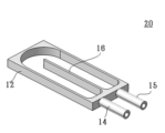
- FIG. 1 is a schematic perspective view of a cooling structure 10 according to one aspect of the present disclosure.
- a cooling structure 10 shown in FIG. 1 has a coolant inlet 14 and a coolant outlet 15 in a housing 12 , and has flow paths partitioned by wall members 16 inside the housing 12 . There may be only one flow path or a plurality of flow paths.
- the wall material 16 may be made of resin, and the housing 12 including the bottom surface, the coolant inlet 14 and the coolant outlet 15 may also be made of resin.
- the housing 12, the coolant inlet 14, the coolant outlet 15, and the wall member 16 may be integrally molded with resin, and the coolant inlet 14, the coolant outlet 15, and the wall member 16 may be separately formed. It may be attached to the housing 12 . From the viewpoints of simplification of the assembly process and reduction in the number of parts, it is preferable to integrate the housing 12, the coolant inlet 14, the coolant outlet 15, and the wall material 16 together.
- Resins include polyethylene resins, polypropylene resins (PP), composite polypropylene resins (PPC), polyphenylene sulfide resins (PPS), polyphthalamide resins (PPA), polybutylene terephthalate resins (PBT), epoxy resin, phenolic resin, polystyrene resin, polyethylene terephthalate resin, polyvinyl alcohol resin, vinyl chloride resin, ionomer resin, polyamide resin, acrylonitrile-butadiene-styrene copolymer (ABS), polycarbonate resin, etc. are mentioned.
- the resin may contain inorganic fillers.
- inorganic fillers include glass, silica, alumina, zircon, magnesium oxide, calcium silicate, calcium carbonate, potassium titanate, silicon carbide, silicon nitride, boron nitride, beryllia, and zirconia.
- Aluminum hydroxide, zinc borate, etc. may be used as an inorganic filler having a flame retardant effect.
- the wall material 16 of the cooling structure 10 is bent into a U shape and provided inside the housing 12 . Therefore, the channel is also U-shaped, and the coolant inlet 14 and the coolant outlet 15 are provided on the same surface of the housing 12 according to the direction of the channel.
- the refrigerant inlet 14 and the refrigerant outlet 15 may be interchanged.
- the shape, width, and length of the flow path are not particularly limited, and can be appropriately set according to the size and shape of the object to be cooled, the required cooling performance, and the like.
- the cross-sectional shape of the flow path in the width direction may be rectangular, circular, elliptical, polygonal other than rectangular, or the like. A rectangle is preferable from the viewpoint of ease of manufacture.
- the wall material 16 forming the flow path may be flat or curved.
- the size of the housing 12, the diameter and length of the coolant inlet 14 and the coolant outlet 15, and the thickness of the wall material 16 are not particularly limited, and may vary depending on the size and shape of the object to be cooled, the required cooling performance, and the like. It can be set as appropriate.
- the housing 12 has a bottom surface and an open top surface.
- a thermally conductive material 18 may be placed on the open top surface. By placing the thermally conductive material 18 on the open upper surface, the open upper surface of the channel is blocked.
- the thermally conductive material 18 is not particularly limited as long as it has higher thermal conductivity than resin, and preferably contains at least one selected from the group consisting of metals and alloys, and preferably contains metal. Examples of metals include aluminum, iron, copper, gold, silver, and stainless steel.
- the thermally conductive material 18 may be composed of a single layer or two or more layers.
- a metal foil, a metal plate, an alloy foil, an alloy plate, or the like can be used as the thermally conductive material 18 composed of a single layer.
- the thermally conductive material 18 composed of two or more layers may have a metal layer and a resin layer. Having a resin layer enables welding to a cooling structure, an object to be cooled, or the like. Resins that can be used in the resin layer include those described above. Examples of the thermally conductive material 18 composed of two or more layers include a two-layer structure in which a metal layer and a resin layer are laminated, a three-layer structure in which a resin layer, a metal layer and a resin layer are laminated in this order, and the like. be done.
- the shape of the metal layer in the thermally conductive material 18 composed of two or more layers may be foil, plate, sheet, film, or the like. From the viewpoint of suppressing the load on the cooling structure 10 due to the difference in expansion coefficients, it may be mesh-like, punching metal, or the like.
- the thermally conductive material 18 placed on the open upper surface may be replaced with a resin member.
- a resin member those mentioned above can be applied, and the members and the cooling structure as a whole may be made of a polypropylene-based resin.
- the resin member placed on the open upper surface is preferably a stretched polypropylene film because it has a high melting point and can be welded.
- FIG. 2 is a schematic perspective view of a cooling structure 20 according to another aspect of the present disclosure.
- the housing 12 is open at both the bottom and the top.
- the wall material 16 preferably extends from the outer frame of the housing 12 .
- the thermally conductive material 18 or the resin member described above may be arranged on at least one of the open bottom surface and top surface.
- the body to be cooled is cooled by disposing the cooling structure 20 with respect to the body to be cooled via the thermally conductive material 18 or a member made of resin.
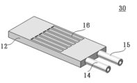
- FIG. 3 is a schematic perspective view of a cooling structure 30 according to another aspect of the present disclosure.
- the cooling structure 30 shown in FIG. 3 is the cooling structure 10 of FIG. 1 in which a portion of the upper surface of the housing 12 is open instead of the entire upper surface. That is, the housing 12 of the cooling structure 30 has a bottom surface and a portion of the top surface, and a portion of the top surface is open.
- a thermally conductive material 18 or a member made of resin may be arranged in the open area of the upper surface.
- the housing 12 Since the housing 12 has a part of the upper surface, the strength of the load received from the upper surface is increased, and the cooling structure 30 can be arranged even in a portion where the load is applied.
- the proportion of the open area on the upper surface can be appropriately designed according to the applied load and required heat dissipation.
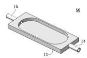
- the cooling structures 40, 50 and 60 shown in FIGS. 4-6 are variations in which the coolant inlet 14 and coolant outlet 15 are oriented differently.
- the refrigerant inlet 14 and the refrigerant outlet 15 may be interchanged.
- the housings 12 of the cooling structures 40, 50 and 60 have a bottom surface and an open top surface, but the bottom surface may also be open as shown in FIG. Instead, it may be partially open.
- FIG. 7 is a schematic perspective view of a cooling structure 70 according to another aspect of the present disclosure.
- a cooling structure 70 shown in FIG. 7A includes a mounting member 72 on the housing 12 .
- frame frames are provided on both sides of the housing 12 as mounting members 72, and bolt mounting holes 74 for mounting bolts are drilled in the frame frames.
- the frame may be made of the same resin as the housing 12 or may be integrally molded with the housing 12 .
- the attachment member 72 is not particularly limited as long as it can be attached to the object to be cooled.
- the frame may be provided with positioning pins for positioning peripheral parts, cutouts, and the like.
- the shape of the frame is not particularly limited, and can be appropriately set according to the shape of the body to be cooled, the shape of the surrounding parts on which the body to be cooled and the cooling structure 70 are arranged, and the like.
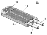
- FIG. 8 is a schematic perspective view of a cooling structure 80 according to another aspect of the disclosure.
- a cooling structure 80 shown in FIG. 8 has a laminated material 19 in which a resin layer is provided on both sides of a metal heat transfer layer, which is arranged inside the housing 12 .
- the laminate material 19 may be a laminate material in which a metal heat transfer layer is laminated with a resin layer. Also, the same material as the thermally conductive material 18 described above may be applied to the laminated material 19 .
- a plurality of flow paths may be formed by the laminated material 19 .
- the laminated material 19 may be processed into an uneven shape by corrugating, embossing, or the like.
- the channel may be partitioned into a plurality of channels by the uneven portion.
- both the wall material 16 and the laminated material 19 are provided, and the refrigerant inlet 14 and the refrigerant outlet 15 are arranged on the same side of the housing 12 .
- the wall material 16 By providing the wall material 16 in this way, the arrangement positions of the coolant inlet 14 and the coolant outlet 15 can be freely designed. Further, when the coolant inlet 14 and the coolant outlet 15 are arranged at one end and the other end of the housing 12, respectively, the laminated member 19 may be arranged without providing the wall member 16. , both wall material 16 and laminate material 19 may be provided.
- FIG. 9(A) is a schematic perspective view of a cooling structure 90 according to another aspect of the present disclosure
- FIG. 9(B) is an exploded view of (A).
- the coolant inlet 14 and the coolant outlet 15 are configured separately from the housing 12, and the header portion 14A having the coolant inlet 14 and the footer portion having the coolant outlet 15 are provided.
- 15A is connected to the housing 12 . If the coolant inlet 14 and the coolant outlet 15 are separate from the housing 12, the position, orientation, size, shape, etc. of the coolant inlet 14 and the coolant outlet 15 are freer than when integrally molded. degree increases.
- the direction of the coolant inlet 14 extends outward in the thickness direction of the cooling structure 90, and the direction of the coolant outlet 15 extends outward in the plane direction of the cooling structure 90.
- the directions of the coolant inlet 14 and the coolant outlet 15 are not limited to this.
- the coolant inlet 14 and the coolant outlet 15 are divided into the header portion 14A and the footer portion 15A, respectively. It is good also as a member.
- the coolant inlet 14 and coolant outlet 15 extend from the same side of the cooling structure, so that the coolant inlet 14 and the coolant outlet 15 are grouped together on this side. Body parts may be placed.
- FIG. 10 is an exploded view showing a schematic of a cooling structure 100 according to another aspect of the present disclosure, and FIG.
- the cooling structure 100 may have a plurality of housings 12 arranged therein, and water channels for circulating a coolant may be provided in the plurality of housings 12 .
- the material of the channel is not particularly limited, and may be made of resin.
- the inflow channel 200, the branch channel 210, and the recovery channel 220 are provided as channels, but the channels are not limited to these channels.
- the coolant in the cooling structure 100 flows from the inflow channel 200 to each housing 12 via the branch channel 210 arranged in the center.
- the refrigerant that has passed through the housing 12 flows into the recovery channel 220 and is recovered.
- the refrigerant may be circulated, in which case the refrigerant recovered in recovery channel 220 is returned to inlet channel 200 .
- the refrigerant recovered in the recovery channel 220 may be reused after being stored in a tank (not shown) or the like.
- the refrigerant that has passed through the housing 12 may be stored in a tank or the like without passing through the recovery waterway 220 .
- Foreign matter may be removed from the refrigerant using a filter or the like before it is reused.
- the housings 12 are arranged on both sides of the branch channel arranged in the center, but the method of arranging the housings 12 is not limited to this. Also, in the cooling structure 100 shown in FIG. 10, the heat conductive material 18 is arranged in each of the housing 12, the inflow channel 200, the branch channel 210, and the recovery channel 220, which will be explained in the first embodiment. A member made of resin may be provided in place of the thermally conductive material 18 as described above.
- FIG. 12 is a schematic perspective view of a cooling structure 110 according to another aspect of the present disclosure.
- the housing 12 has a bottom surface, and the housing 12 has an extension portion 76 extending outward on the bottom surface side.
- the housing 12, the bottom surface, and the extension portion 76 may be integrated, or they may be integrally molded with resin.
- the housing 12, the bottom surface, the extension portion 76, the coolant inlet 14, the coolant outlet 15, and the wall material 16 may be integrated.
- the shape of the extension part 76 is not particularly limited, and can be appropriately set according to the shape of the body to be cooled, the shape of the surrounding parts in which the body to be cooled and the cooling structure 70 are arranged, and the like.
- the extension part 76 may be continuously on the same plane from the bottom surface without a step, or may have a step.
- the extending portion 76 extends in the surface direction of the cooling structure 110, but may extend in the thickness direction.
- the extending direction in the thickness direction may be the bottom side or the top side.
- the extending portion 76 may extend in the planar direction and then bend in the thickness direction.
- the bending angle can also be set appropriately. It may have a curvature at the bending position.
- the bend may be bent twice or more than once.
- the extension portions 76 extending in the thickness direction are provided at both ends in the length direction or both ends in the width direction of the cooling structure 110, the body to be cooled is held by the extension portions 76 at both ends.
- the extension portion 76 may be installed for purposes other than stability and adhesion.
- the extensions 76 extend in the width direction of the cooling structure 110, but may extend in the length direction. Further, the extending portion 76 may extend in both the width direction and the length direction of the cooling structure 110 and be arranged around the housing 12 . Further, the extension 76 may be partially extended to have an extension (not shown), which enlarges the area of the extension 76 .
- the shape of the extended portion is not particularly limited. The thickness and area of the extension portion 76 can be appropriately designed.
- cooling structure 10: housing, 14: refrigerant inlet, 15: refrigerant outlet, 16: wall material, 18: heat conduction 19: Laminated material 72: Mounting member 74: Bolt mounting hole 76: Extension part 200: Inflow channel 210: Branch channel 220: Recovery channel
Landscapes
- Engineering & Computer Science (AREA)
- Manufacturing & Machinery (AREA)
- Chemical & Material Sciences (AREA)
- Chemical Kinetics & Catalysis (AREA)
- Electrochemistry (AREA)
- General Chemical & Material Sciences (AREA)
- Microelectronics & Electronic Packaging (AREA)
- Physics & Mathematics (AREA)
- Thermal Sciences (AREA)
- Cooling Or The Like Of Electrical Apparatus (AREA)
- Cooling Or The Like Of Semiconductors Or Solid State Devices (AREA)
Priority Applications (4)
| Application Number | Priority Date | Filing Date | Title |
|---|---|---|---|
| EP22907423.2A EP4451326A4 (en) | 2021-12-14 | 2022-12-12 | COOLING STRUCTURE |
| US18/719,063 US20250040080A1 (en) | 2021-12-14 | 2022-12-12 | Cooling structure |
| CN202280081994.7A CN118476021A (zh) | 2021-12-14 | 2022-12-12 | 冷却结构体 |
| JP2023567780A JPWO2023112899A1 (https=) | 2021-12-14 | 2022-12-12 |
Applications Claiming Priority (2)
| Application Number | Priority Date | Filing Date | Title |
|---|---|---|---|
| JP2021202702 | 2021-12-14 | ||
| JP2021-202702 | 2021-12-14 |
Publications (1)
| Publication Number | Publication Date |
|---|---|
| WO2023112899A1 true WO2023112899A1 (ja) | 2023-06-22 |
Family
ID=86774714
Family Applications (1)
| Application Number | Title | Priority Date | Filing Date |
|---|---|---|---|
| PCT/JP2022/045723 Ceased WO2023112899A1 (ja) | 2021-12-14 | 2022-12-12 | 冷却構造体 |
Country Status (5)
| Country | Link |
|---|---|
| US (1) | US20250040080A1 (https=) |
| EP (1) | EP4451326A4 (https=) |
| JP (1) | JPWO2023112899A1 (https=) |
| CN (1) | CN118476021A (https=) |
| WO (1) | WO2023112899A1 (https=) |
Cited By (1)
| Publication number | Priority date | Publication date | Assignee | Title |
|---|---|---|---|---|
| EP4668391A1 (en) * | 2024-06-17 | 2025-12-24 | Prime Planet Energy & Solutions, Inc. | Battery assembly and battery pack |
Citations (4)
| Publication number | Priority date | Publication date | Assignee | Title |
|---|---|---|---|---|
| JP2019204897A (ja) * | 2018-05-24 | 2019-11-28 | 三井化学株式会社 | 冷却ジャケット |
| JP2020003132A (ja) | 2018-06-28 | 2020-01-09 | 昭和電工パッケージング株式会社 | 樹脂融着製熱交換器 |
| JP2021096041A (ja) | 2019-12-18 | 2021-06-24 | 昭和電工株式会社 | 熱交換器 |
| JP2021111466A (ja) * | 2020-01-07 | 2021-08-02 | 昭和電工パッケージング株式会社 | 熱交換器 |
Family Cites Families (4)
| Publication number | Priority date | Publication date | Assignee | Title |
|---|---|---|---|---|
| FR3003938A1 (fr) * | 2013-03-29 | 2014-10-03 | Valeo Systemes Thermiques | Plaque d'echange thermique pour gestion thermique de batterie et procede de fabrication associe. |
| KR20210135570A (ko) * | 2019-03-28 | 2021-11-15 | 미쯔이가가꾸가부시끼가이샤 | 냉각 유닛, 냉각 장치, 전지 구조체 및 전동 차량 |
| WO2020235449A1 (ja) * | 2019-05-21 | 2020-11-26 | 株式会社巴川製紙所 | 温調ユニット |
| JP7781514B2 (ja) * | 2019-12-25 | 2025-12-08 | 株式会社Dnp高機能マテリアル彦根 | 熱交換器およびそのインナーフィン |
-
2022
- 2022-12-12 CN CN202280081994.7A patent/CN118476021A/zh not_active Withdrawn
- 2022-12-12 WO PCT/JP2022/045723 patent/WO2023112899A1/ja not_active Ceased
- 2022-12-12 JP JP2023567780A patent/JPWO2023112899A1/ja active Pending
- 2022-12-12 US US18/719,063 patent/US20250040080A1/en not_active Abandoned
- 2022-12-12 EP EP22907423.2A patent/EP4451326A4/en active Pending
Patent Citations (4)
| Publication number | Priority date | Publication date | Assignee | Title |
|---|---|---|---|---|
| JP2019204897A (ja) * | 2018-05-24 | 2019-11-28 | 三井化学株式会社 | 冷却ジャケット |
| JP2020003132A (ja) | 2018-06-28 | 2020-01-09 | 昭和電工パッケージング株式会社 | 樹脂融着製熱交換器 |
| JP2021096041A (ja) | 2019-12-18 | 2021-06-24 | 昭和電工株式会社 | 熱交換器 |
| JP2021111466A (ja) * | 2020-01-07 | 2021-08-02 | 昭和電工パッケージング株式会社 | 熱交換器 |
Non-Patent Citations (1)
| Title |
|---|
| See also references of EP4451326A4 |
Cited By (1)
| Publication number | Priority date | Publication date | Assignee | Title |
|---|---|---|---|---|
| EP4668391A1 (en) * | 2024-06-17 | 2025-12-24 | Prime Planet Energy & Solutions, Inc. | Battery assembly and battery pack |
Also Published As
| Publication number | Publication date |
|---|---|
| JPWO2023112899A1 (https=) | 2023-06-22 |
| US20250040080A1 (en) | 2025-01-30 |
| EP4451326A1 (en) | 2024-10-23 |
| CN118476021A (zh) | 2024-08-09 |
| EP4451326A4 (en) | 2025-05-21 |
Similar Documents
| Publication | Publication Date | Title |
|---|---|---|
| CN102637655B (zh) | 热交换器 | |
| JP2016036194A (ja) | 電力変換装置 | |
| CN107517596B (zh) | 电力转换装置 | |
| WO2023112899A1 (ja) | 冷却構造体 | |
| JP2008221951A (ja) | 自動車用電子部品の冷却装置 | |
| JP6961047B1 (ja) | 電力変換装置 | |
| US12538462B2 (en) | Cooler for power electronics | |
| US20250185206A1 (en) | Cooling structure and structure | |
| JP7708309B2 (ja) | 冷却構造体及び構造体 | |
| JP2021097134A (ja) | 冷却装置 | |
| EP4528802A1 (en) | Cooling structure and structure | |
| JP4503202B2 (ja) | ヒートシンクの製造方法 | |
| JP7693288B2 (ja) | 熱交換器 | |
| US20250327631A1 (en) | Cooling structure and structure | |
| JP4164726B2 (ja) | 液冷式回路基板兼用回路ケースの製造方法 | |
| JP6139342B2 (ja) | 積層ユニット | |
| WO2023210711A1 (ja) | ジョイント部品、冷却構造体及び構造体 | |
| WO2023210710A1 (ja) | 冷却構造体及び構造体 | |
| JP7619164B2 (ja) | 冷却構造体 | |
| JP2025171420A (ja) | 熱交換器、及び熱交換器の製造方法 | |
| WO2023228676A1 (ja) | 冷却構造体用樹脂部品、冷却構造体及び構造体 | |
| JP2022188312A (ja) | パワーモジュールおよびパワーモジュールの製造方法 | |
| JP2006023034A (ja) | 熱交換器用チューブの製造方法、熱交換器用チューブおよび熱交換器 | |
| CN121100594A (zh) | 散热部件及具备散热部件的电路结构体 |
Legal Events
| Date | Code | Title | Description |
|---|---|---|---|
| 121 | Ep: the epo has been informed by wipo that ep was designated in this application |
Ref document number: 22907423 Country of ref document: EP Kind code of ref document: A1 |
|
| WWE | Wipo information: entry into national phase |
Ref document number: 202280081994.7 Country of ref document: CN |
|
| WWE | Wipo information: entry into national phase |
Ref document number: 18719063 Country of ref document: US Ref document number: 2023567780 Country of ref document: JP |
|
| WWE | Wipo information: entry into national phase |
Ref document number: 2022907423 Country of ref document: EP |
|
| NENP | Non-entry into the national phase |
Ref country code: DE |
|
| ENP | Entry into the national phase |
Ref document number: 2022907423 Country of ref document: EP Effective date: 20240715 |