WO2023112474A1 - 水質測定装置 - Google Patents
水質測定装置 Download PDFInfo
- Publication number
- WO2023112474A1 WO2023112474A1 PCT/JP2022/039050 JP2022039050W WO2023112474A1 WO 2023112474 A1 WO2023112474 A1 WO 2023112474A1 JP 2022039050 W JP2022039050 W JP 2022039050W WO 2023112474 A1 WO2023112474 A1 WO 2023112474A1
- Authority
- WO
- WIPO (PCT)
- Prior art keywords
- water
- dilution
- liquid level
- container
- residual chlorine
- Prior art date
- Legal status (The legal status is an assumption and is not a legal conclusion. Google has not performed a legal analysis and makes no representation as to the accuracy of the status listed.)
- Ceased
Links
Images


Classifications
-
- G—PHYSICS
- G01—MEASURING; TESTING
- G01N—INVESTIGATING OR ANALYSING MATERIALS BY DETERMINING THEIR CHEMICAL OR PHYSICAL PROPERTIES
- G01N33/00—Investigating or analysing materials by specific methods not covered by groups G01N1/00 - G01N31/00
- G01N33/18—Water
- G01N33/182—Specific anions in water
-
- G—PHYSICS
- G01—MEASURING; TESTING
- G01N—INVESTIGATING OR ANALYSING MATERIALS BY DETERMINING THEIR CHEMICAL OR PHYSICAL PROPERTIES
- G01N1/00—Sampling; Preparing specimens for investigation
- G01N1/28—Preparing specimens for investigation including physical details of (bio-)chemical methods covered elsewhere, e.g. G01N33/50, C12Q
- G01N1/38—Diluting, dispersing or mixing samples
-
- G—PHYSICS
- G01—MEASURING; TESTING
- G01N—INVESTIGATING OR ANALYSING MATERIALS BY DETERMINING THEIR CHEMICAL OR PHYSICAL PROPERTIES
- G01N33/00—Investigating or analysing materials by specific methods not covered by groups G01N1/00 - G01N31/00
- G01N33/18—Water
-
- G—PHYSICS
- G01—MEASURING; TESTING
- G01N—INVESTIGATING OR ANALYSING MATERIALS BY DETERMINING THEIR CHEMICAL OR PHYSICAL PROPERTIES
- G01N1/00—Sampling; Preparing specimens for investigation
- G01N1/28—Preparing specimens for investigation including physical details of (bio-)chemical methods covered elsewhere, e.g. G01N33/50, C12Q
- G01N1/38—Diluting, dispersing or mixing samples
- G01N2001/383—Diluting, dispersing or mixing samples collecting and diluting in a flow of liquid
Definitions
- the present invention relates to a water quality measuring device. More particularly, the present invention relates to a water quality measuring device including a dilution device and a residual chlorine concentration measuring device.
- Patent Document 1 discloses a residual chlorine concentration measuring device that can avoid outputting an erroneous measurement value when the residual chlorine concentration of the water to be measured exceeds the measurable range.
- the measuring device described in Patent Document 1 can determine whether the residual chlorine concentration is within the measurable range, but does not have the function of measuring the residual chlorine concentration when it is not within the measurable range.
- the main object of the present invention is to provide an apparatus capable of quantifying high-concentration residual chlorine.
- the present invention a dilution device for preparing sample water containing raw water and dilution water; a residual chlorine concentration measuring device for measuring the residual chlorine concentration of the sample water,
- the dilution device a container containing the sample water; a first liquid level detection unit that detects a first liquid level in the container; a second liquid level detection unit that detects a second liquid level in the container; a raw water injection unit that injects the raw water into the container until the first liquid level detection unit detects the first liquid level; a dilution water injection unit that injects the dilution water into the container to dilute the raw water until the second liquid level detection unit detects the second liquid level;
- a water quality measuring device comprising: The dilution device a discharge unit for discharging the sample water contained in the container until the first liquid level detection unit detects the first liquid level; After the discharge part discharges the sample water, the dilution water injection part injects the dilution water into the container until the second liquid level detection part detects the
- the dilution device may include a circulation section that circulates the sample water in the container.
- the residual chlorine concentration measuring device may measure the residual chlorine concentration of the sample water based on the absorbance of the sample water colored by a reagent.
- the reagent may be an N,N-diethyl-1,4-phenylenediamine reagent.
- the raw water may have a residual chlorine concentration of more than 8 mg/L.
- the raw water may be wash water for wash-in-place.
- the present invention provides a device that can quantify high-concentration residual chlorine. Note that the effects of the present invention are not limited to the effects described here, and may be any of the effects described in this specification.
- FIG. 4 is a schematic diagram showing a sample water reservoir
- a water quality measurement device includes a dilution device that prepares sample water containing raw water and dilution water, and a residual chlorine concentration measurement device that measures the residual chlorine concentration of the sample water.
- the measuring object of the residual chlorine concentration measuring device is not the raw water itself but the sample water prepared by diluting the raw water. Therefore, even if the residual chlorine concentration in the raw water exceeds the concentration range that can be measured by the residual chlorine concentration measuring device, the residual chlorine concentration in the raw water can be quantified based on the residual chlorine concentration in the sample water.
- FIG. 1 is a schematic diagram showing an example of a water quality measuring device 1.
- the water quality measuring device 1 includes a diluting device 100 and a residual chlorine concentration measuring device 200 .
- the water quality measuring device 1 preferably includes a sample water reservoir 70 .
- the dilution device 100 dilutes the raw water R, and if necessary, re-dilutes the raw water R to prepare the sample water S, and transfers the sample water S to the sample water reservoir 70 .
- the sample water S in the sample water reservoir 70 is transferred to the residual chlorine concentration measuring device 200 .
- the residual chlorine concentration measuring device 200 measures the residual chlorine concentration of the sample water S.
- a series of processes including preparation of the sample water S and measurement of the residual chlorine concentration may be performed once or twice or more. By performing the series of processes twice or more, the water quality measuring device 1 can continuously quantify the residual chlorine concentration of the raw water R over time.
- the dilution device 100 will be described with reference to FIG.
- the dilution device 100 prepares sample water S composed of raw water R and dilution water D.
- the sample water S is just an example, and the sample water prepared in the dilution device may contain components other than raw water and dilution water, for example.
- raw water R can be stored in a raw water tank 10, for example.
- the dilution water D can be stored in the sample water tank 20, for example.
- the upper limit of the residual chlorine concentration of raw water R may vary depending on the dilution performance of the dilution device 100 and the measurement performance of the residual chlorine concentration measurement device 200, but may be, for example, 8000 mg/L or less.
- the lower limit of the residual chlorine concentration of raw water R may be, for example, 8 mg/L or higher, 8 mg/L or higher, 50 mg/L or higher, 100 mg/L or higher, 200 mg/L or higher, or 500 mg/L or higher.
- the diluting device 100 includes a container 30 in which sample water S is stored.
- the container 30 may have, for example, a cylindrical container main body 31 , a bottom surface portion 32 provided at one end of the container main body 31 , and a top surface portion 33 provided at the other end of the container main body 31 .
- the container main body 31 is a main body portion in which the sample water S is accommodated.
- the bottom portion 32 is located on the bottom surface of the container 30 .
- a pipe which will be described later, can be connected to the bottom surface portion 32 .
- the top surface portion 33 is located on the top surface of the container 30 .
- a pipe which will be described later, can be connected to the top surface portion 33 .
- the shape of the container body 31 may be cylindrical as described above, but is not limited to this, and may be a shape appropriately selected by those skilled in the art. Shapes other than the cylindrical shape include, for example, the shape of a square tube, the shape of a column, and the shape of a box.
- the size of the container body 31 may be appropriately set by a person skilled in the art according to the amount of sample water S to be accommodated (the amount of raw water R and dilution water D). As an example, when the container body 31 is cylindrical, it may have an outer diameter of 20 mm to 30 mm, an inner diameter of 15 mm to 25 mm, and a height of 300 mm to 400 mm, but is not limited to these.
- the material of the container body 31 is preferably highly resistant to chlorine, and may be polyacrylic resin, for example.
- the diluting device 100 includes a first liquid level detector 41 that detects a first liquid level L1 in the container 30 and a second liquid level detector 42 that detects a second liquid level L2 in the container 30. , provided.
- the second liquid level L2 is located above the first liquid level L1.
- the upper side of the container 30 means the upper side when the top surface portion 33 side is the upper side and the bottom surface portion 32 side is the lower side.
- the first liquid level detection section 41 and the second liquid level detection section 42 may be configured by known liquid level detection means.
- the liquid level detection means include capacitance, float, electrode, optical, ultrasonic, guide pulse, and pressure level sensors.
- the first liquid level detector 41 is arranged in the container 30 at a position where it can detect the first liquid level L1.
- the second liquid level detector 42 is arranged in the container 30 at a position where the second liquid level L2 can be detected.
- the positions at which the first liquid level detection unit 41 and the second liquid level detection unit 42 are arranged depend on the characteristics of the liquid level detection means used as the first liquid level detection unit 41 and the second liquid level detection unit 42. may be determined as appropriate.
- the diluting device 100 shown in FIG. 1 has two capacitance type liquid level sensors on the outside of the container body 31 as the first liquid level detection section 41 and the second liquid level detection section 42 . . Specifically, the two sensor bodies of the capacitive liquid level sensor are arranged at positions corresponding to the first liquid level L1 and the second liquid level L2, respectively.
- the dilution device 100 includes a raw water injection section that injects raw water R into the container 30 until the first liquid level detection section 41 detects the first liquid level L1.
- the raw water injection unit may be composed of, for example, a pipe 11, a solenoid valve SV1, and a pipe 12 that connect the raw water tank 10 and the container 30. As shown in FIG.
- the pipe 12 may be connected to the top surface portion 33 of the container 30, for example. Injection of the raw water R in the raw water tank 10 into the container 30 becomes possible or impossible by opening and closing the solenoid valve SV1. Specifically, by opening the electromagnetic valve SV1 until the first liquid level detection unit 41 detects the first liquid level L1, the raw water R in the raw water tank 10 flows through the pipes 11 and 12 into the container.
- the injection of the raw water R into the container 30 is stopped by closing the electromagnetic valve SV1. Opening and closing of the solenoid valve SV1 can be controlled by, for example, a controller (not shown) electrically connected to the solenoid valve SV1.
- the solenoid valve is an example of a valve, and valves other than the solenoid valve may be selected.
- a predetermined amount of raw water R can be injected into the container 30 by operating the raw water injection unit as described above.
- the amount of raw water R to be injected is increased or decreased by changing the position of the first liquid level L1 detected by the first liquid level detection section 41 upward or downward.
- the dilution device 100 includes a dilution water injection section that injects the dilution water D into the container 30 to dilute the raw water R until the second liquid level detection section 42 detects the second liquid level L2.
- the dilution water injection section may be configured by, for example, a pipe 21, a solenoid valve SV2, and a pipe 22 that connect the dilution water tank 20 and the container 30 together.
- the pipe 22 may be connected to the top surface portion 33 of the container 30, for example.
- the dilution water D in the dilution water tank 20 is allowed to pass through the pipes 21 and 22. is injected into the container 30.
- the raw water R in the container 30 is diluted with the dilution water D, and the sample water S composed of the raw water R and the dilution water D is prepared.
- the injection of the dilution water D into the container 30 is stopped by closing the electromagnetic valve SV2.
- the opening and closing of the solenoid valve SV2 can be controlled, for example, by the control device described above.
- a predetermined amount of dilution water D can be injected into the container 30 by operating the dilution water injection unit as described above.
- the amount of diluted water D to be injected is increased or decreased by changing the position of the second liquid level L2 detected by the second liquid level detection section 42 upward or downward.
- the dilution device 100 predetermined amounts of raw water R and dilution water D are injected into the container 30, and the raw water R is diluted. As a result, the raw water R is diluted by a predetermined ratio, and the sample water S is prepared.
- the dilution factor X of the raw water R in the dilution of the raw water R is calculated from the amounts of the raw water R, dilution water D, and sample water S as follows.
- the amount AR of the raw water R injected into the container 30 is the amount when the water surface of the raw water R reaches the first liquid surface L1.
- the amount AD of the dilution water D injected into the container 30 is the amount injected by the time the water surface of the sample water S reaches the second liquid surface L2.
- the raw water R may be diluted again.
- the raw water R may be re-diluted twice or more.
- dilution of raw water specifically means diluting the raw water by injecting dilution water into the raw water in the container.
- Re-dilution of raw water specifically means re-diluting the raw water by injecting the dilution water into the sample water containing the raw water in the container after diluting the raw water. Therefore, in the dilution device, if the raw water is diluted once and then re-diluted twice, the raw water is diluted three times in total. A case where the dilution device re-dilutes the raw water will be described below.
- the dilution device 100 may further include a discharge section for discharging the sample water S contained in the container 30 until the first liquid level detection section 41 detects the first liquid level L1.
- the discharge part may be composed of, for example, a pipe 51 connected to the bottom part 32 of the container 30, a solenoid valve SV3, pipes 52, 53, 54, a solenoid valve SV6, and a pipe 55. By opening and closing the solenoid valves SV3 and SV6, the sample water S stored in the container 30 can be discharged or not.
- the sample water S in the container 30 is detected by the pipes 51, 52, and It is discharged as waste water W through 53, 54, 55. Thereafter, when the first liquid level detector 41 detects the first liquid level L1, the electromagnetic valves SV3 and SV6 are closed, thereby stopping the discharge of the sample water S contained in the container 30.
- FIG. The opening and closing of the solenoid valves SV3 and SV6 can be controlled, for example, by the control device described above.
- Re-dilution may be performed after the discharge unit discharges the sample water S from the container 30 and the liquid surface of the sample water S reaches the first liquid surface L1. That is, in the dilution apparatus 100, after the discharge section discharges the sample water S, until the second liquid level detection section 42 detects the second liquid level L2, the dilution water injection section supplies the dilution water to the container 30. D may be injected and re-dilution of raw water R may be performed. Injection of the dilution water S in the re-dilution may be performed by opening the solenoid valve SV2 until the second liquid level detection unit 42 detects the second liquid level L2, as described above.
- the dilution ratios for dilution and re-dilution may be the same or different. That is, the dilution ratio may be changed after dilution of the raw water R and before re-dilution. Further, when the raw water R is re-diluted twice or more, the dilution ratio may be changed after the re-dilution and before the next re-dilution. The change in the dilution ratio is based on the position of the first liquid level L1 detected by the first liquid level detection section 41 and/or the position of the second liquid level L2 detected by the second liquid level detection section 42.
- the position of the first liquid level L1 detected by the first liquid level detection section 41 and/or The detected position of the second liquid level L2 may be changed. Further, when the raw water R is re-diluted twice or more, after the re-dilution and before the next re-dilution, the position of the first liquid level L1 detected by the first liquid level detection unit 41 and/or the first The position of the second liquid level L2 detected by the two liquid level detectors 42 may be changed.
- the dilution ratio and the number of times of re-dilution in the dilution device 100 may be set according to the residual chlorine concentration of the raw water R and the residual chlorine concentration measurable by the residual chlorine concentration measurement device 200.
- the residual chlorine concentration of the raw water R may exceed the concentration measurable by the residual chlorine concentration measuring device 200 . Therefore, it is preferable that the residual chlorine concentration of the raw water R is measured in advance by manual analysis, and the dilution factor and the number of times of re-dilution are set so that the residual chlorine concentration can be measured by the residual chlorine concentration measuring device 200 .
- the raw water R When the final dilution ratio of the raw water R is high (for example, several tens of times or more), dilution is performed multiple times (that is, re-dilution is performed once or more) in order to reduce errors during dilution. is preferred.
- the raw water R when the final dilution ratio of the raw water R is 1000 times (when the raw water R is diluted 1000 times), the raw water R may be diluted 1000 times by one dilution, but preferably multiple 1000-fold dilution can be achieved by 1-fold dilution.
- the raw water R is diluted 10-fold by the first dilution, then further diluted 10-fold by the second dilution (first re-dilution), and diluted three times (second re-dilution) may be further diluted 10-fold with As a result, the final dilution ratio of the raw water R becomes 1000 times.
- the dilution device 100 may further include a circulation section that circulates the water sample S in the container 30 . Thereby, the sample water S in the container 30 can be homogenized. By homogenizing the sample water S, the measurement accuracy of the residual chlorine concentration in the residual chlorine concentration measuring device 200 can be improved.
- FIG. 2 is a schematic diagram showing the container 30 and the circulation section 90.
- the circulation unit 90 may have a flow path 91 connecting the bottom surface portion 32 and the top surface portion 33 and a pump P, for example.
- the circulation unit 90 may, for example, inject the sample water S discharged from the bottom surface portion 32 into the container 30 from the top surface portion 33 via the flow path 91 . Thereby, the sample water S in the container 30 can be circulated from bottom to top.
- the pump P shown in FIG. 2 may be the same as or different from the pump P in FIG. 1, which will be described later.
- the circulation unit 90 may have a valve (not shown).
- the valves may be, for example, the solenoid valves SV3, SV4 shown in FIG.
- the circulation of the sample water S by the circulation unit 90 may be performed once or multiple times.
- the circulation of the sample water S is preferably performed after the raw water R has been diluted and after the raw water R has been re-diluted.
- the sample water S prepared in the dilution device 100 is preferably transferred to the sample water reservoir 70 and then supplied to the residual chlorine concentration measuring device 200 .
- the dilution device 100 is set so that the dilution ratio in one dilution is 10 times. Specifically, in the container 30 of the diluting device 100, the amount of water when reaching the first liquid level L1 is 10% (10 mL), and the amount of water when reaching the second liquid level L2 is 100% (100 mL). is set to be Therefore, the raw water R is injected until it reaches the first liquid level L1, and the dilution water D is injected until it reaches the second liquid level L2. is mixed at a ratio of 90% (90 mL) to prepare 10-fold diluted sample water S (100 mL).
- Table 1 below shows the states of the diluter 100, the solenoid valves SV1 to SV6, and the pump P in one example of the above process.
- the pump P is in the "ON" state in Table 1, the pump is driven to transfer water.
- step S0 is the initial state. In step S0, all solenoid valves SV1-SV6 are closed and pump P is off.
- step S1 the solenoid valve SV1 is opened.
- “100% raw water injection” means that the raw water R is injected into the container 30 until it reaches the second liquid level L2. Specifically, it means that the raw water R is injected into the container 30 until the second liquid level detector 42 detects the second liquid level L2.
- step S2 the solenoid valve SV1 is closed. As a result, the “raw water 100% filling” is stopped, and only the raw water R is filled up to the second liquid level L2 in the container 30 .
- step S3 the solenoid valves SV3 and SV6 are opened. As a result, “discharge all the raw water in the container” is started.
- step S4 the solenoid valves SV3 and SV6 are closed. As a result, “discharge all the raw water in the container” is stopped, and the container 30 becomes empty. The inner wall of the container 30 is washed away with the raw water R by steps S3 and S4.
- step S5 the solenoid valves SV3, SV4 and SV6 are opened and the pump P is turned on. As a result, “discharge the raw water in the pipe” is started.
- step S6 the solenoid valves SV3, SV4 and SV6 are closed and the pump P is turned off. As a result, “discharge raw water in pipe” is stopped.
- step S7 the solenoid valve SV1 is opened.
- the "raw water 10% injection” is started.
- “10% raw water injection” means that the raw water R is injected into the container 30 until it reaches the first liquid level L1. Specifically, it means that the raw water R is injected into the container 30 until the first liquid level detector 41 detects the first liquid level L1.
- step S8 the solenoid valve SV1 is closed. As a result, the “raw water 10% filling” is stopped, and the raw water R is filled up to the first liquid level L1 in the container 30 .
- step S9 the solenoid valve SV2 is opened.
- "90% injection of dilution water” means that the dilution water D is injected into the container 30 until it reaches the second liquid level L2. Specifically, it means that the dilution water D is injected into the container 30 until the second liquid level detector 42 detects the second liquid level L2.
- step S10 the solenoid valve SV2 is closed. As a result, the “90% injection of dilution water” is stopped, and the state in which the dilution water D is injected into the container 30 up to the second liquid level L2 is reached.
- sample water S containing 10% raw water R and 90% diluted water D is prepared in container 30 . That is, the dilution of the raw water R is completed, and the raw water R is diluted 10 times in the container 30 .
- step S11 the solenoid valves SV3 and SV4 are opened and the pump P is turned on.
- step S12 the solenoid valves SV3 and SV4 are closed and the pump P is turned off. This stops the "sample water circulation".
- the "sample water circulation” can be performed at a speed of 300 mL/min for 30 seconds, for example.
- step S13 the solenoid valves SV3 and SV6 are opened. As a result, “10% of the sample water in the container is discharged” is started.
- “discharge up to 10% of the sample water in the container” means that the sample water S in the container is discharged until it reaches the first liquid level L1. Specifically, it means that the sample water S in the container is discharged until the first liquid level detector 41 detects the first liquid level L1.
- step S14 the solenoid valves SV3 and SV6 are closed. As a result, the "discharge up to 10% of the sample water in the container” is stopped, and 10% (10 mL) of the sample water S remains in the container 30 .
- step S15 the solenoid valves SV3, SV4 and SV6 are opened and the pump P is turned on. As a result, “discharge the water in the pipe” is started.
- step S16 the solenoid valves SV3, SV4 and SV6 are closed and the pump P is turned off. As a result, “discharge water in pipe” is stopped.
- step S17 the solenoid valve SV2 is opened. As a result, "90% injection of dilution water” is started.
- step S18 the solenoid valve SV2 is closed. As a result, the “90% injection of dilution water” is stopped, and the state in which the dilution water D is injected into the container 30 up to the second liquid level L2 is reached.
- the sample water S 100 mL after re-dilution containing 10% (10 mL) of the sample water S and 90% (90 mL) of the dilution water D is prepared in the container 30 . That is, the re-dilution of the raw water R is completed, and the raw water R is diluted 100 times in the container 30 .
- step S19 the solenoid valves SV3 and SV4 are opened and the pump P is turned on. This starts the “sample water circulation”.
- step S20 the solenoid valves SV3 and SV4 are closed and the pump P is turned off. This stops the "sample water circulation”.
- step S21 the solenoid valves SV3 and SV5 are opened. As a result, the “transfer of sample water to the sample water reservoir” is started, and the sample water S in the container 30 is transferred to the sample water reservoir 70 .
- step S22 the solenoid valves SV3 and SV5 are closed. As a result, the "transfer of sample water to the sample water reservoir” is stopped.
- step S23 the solenoid valves SV4 and SV6 are opened. As a result, “discharge the water in the pipe” is started.
- step S24 the solenoid valves SV4 and SV6 are closed. As a result, “discharge water in pipe” is stopped.
- the raw water R is diluted 100 times and the prepared sample water S can be transferred to the sample water reservoir 70 by the example of the treatment process detailed above.
- steps S13 to S20 may be performed again after step S20 in Table 1 above.
- FIG. 3 is a schematic diagram showing the sample water reservoir 70.
- the sample water reservoir 70 may have, for example, a sample water tank 71 and a sample water container 72 arranged inside the sample water tank 71 .
- the dilution device 100 may include a sample water transfer section that transfers the sample water S in the container 30 to the sample water storage section 70 .
- the sample water transfer unit may be composed of, for example, a pipe 51 connected to the bottom surface 32 of the container 30, a solenoid valve SV3, pipes 52, 53, 56, a solenoid valve SV5, and a pipe 57 shown in FIG. .
- the sample water S in the container 30 can be transferred to the sample water reservoir 70 or not.
- the solenoid valves SV3 and SV5 By opening the solenoid valves SV3 and SV5, the sample water S in the container 30 is transferred to the sample water reservoir 70 through the pipes 51, 52, 53, 56 and 57. As shown in FIGS.
- the sample water S that has passed through the pipe 57 may be stored in the sample water container 72 .
- the sample water S stored in the sample water container 72 may be supplied to the residual chlorine concentration measuring device 200 through the pipe 81 .
- the sample water S overflowing from the sample water container 72 and flowing into the sample water tank 71 may be discharged as waste water W through the pipe 82 .
- the sample water storage unit 70 By providing the sample water storage unit 70, the sample water S before being transferred to the residual chlorine concentration measuring device 200 can be temporarily stored. This makes it easier to adjust the amount and timing of the sample water S sent to the residual chlorine concentration measuring device 200 .
- the sample water S in the container 30 is finally transferred to the residual chlorine concentration measuring device 200 .
- the residual chlorine concentration measuring device 200 measures the residual chlorine concentration of the sample water S.
- the residual chlorine concentration measuring device 200 is preferably a device that measures the residual chlorine concentration of the sample water S based on the absorbance of the sample water S colored by the reagent.
- the device may be any device known in the art.
- the residual chlorine concentration measuring device using the absorbance method is suitable for continuous operation and contributes to the reduction of the load of maintenance work.
- reagents examples include N,N-diethyl-1,4-phenylenediamine reagent (DPD reagent) and 3,3'-dimethylbenzidine reagent (o-tolidine reagent).
- DPD reagent N,N-diethyl-1,4-phenylenediamine reagent
- o-tolidine reagent 3,3'-dimethylbenzidine reagent
- the reagent used in the residual chlorine concentration measuring device 200 is preferably a DPD reagent.
- the raw water R of residual chlorine concentration is calculated. Calculation of the residual chlorine concentration of the raw water R may be performed by the residual chlorine concentration measuring device 200, or may be performed by another computing device (not shown). This completes the determination of the residual chlorine concentration of the raw water R.
- the residual chlorine in the sample water S is The dilution ratio of the raw water R in the dilution device 100 may be changed according to the concentration.
- the change of the dilution factor may be performed by the controller (not shown), for example.
- the controller not shown
- the dilution ratio of the raw water R in the dilution device 100 is set low so that the residual chlorine concentration of the sample water S becomes higher. you can For example, when the residual chlorine concentration of the sample water S is higher than the measurable range, the dilution ratio of the raw water R in the dilution device may be set high so that the residual chlorine concentration of the sample water S becomes lower. .
- the raw water is diluted by the diluting device before being supplied to the residual chlorine concentration measuring device.
- a sample water prepared by diluting raw water is measured by a residual chlorine concentration measuring device. Therefore, even if the residual chlorine concentration in the raw water exceeds the concentration measurable by the residual chlorine concentration measuring device, the residual chlorine concentration in the raw water can be quantified by measuring the residual chlorine concentration in the sample water. That is, the water quality measuring device of this embodiment can automatically quantify the high concentration of residual chlorine. By using the water quality measuring device of this embodiment, it is possible to automatically and continuously quantify the residual chlorine concentration in a water system having a high residual chlorine concentration.
- the residual chlorine concentration of raw water continuously measured by the device can be affected by pH fluctuations.
- the water quality measuring device of this embodiment since the raw water supplied to the residual chlorine concentration measuring device is in a diluted state, the influence of the pH fluctuation of the raw water on the residual chlorine concentration measurement can be reduced. Furthermore, even if there are factors that can interfere with the measurement of residual chlorine concentration in the raw water (for example, if the raw water is colored, or if chlorine ions and salts are mixed in), the raw water Dilution can also reduce the influence of this factor on residual chlorine concentration measurement. As a result, the accuracy of residual chlorine concentration measurement can be improved.
- the water quality measuring device of this embodiment is suitable for quantifying the residual chlorine concentration of raw water with a high residual chlorine concentration. Therefore, the water quality measuring device may be used, for example, in Cleaning In Place (CIP) where cleaning water containing high-concentration residual chlorine is used. That is, the water quality measuring device of the present embodiment may be for stationary cleaning, and the raw water used in the water quality measuring device may be cleaning water for stationary cleaning.
- CIP Cleaning In Place
- the water quality measuring apparatus of the present embodiment is used, for example, in a water system whose pH can fluctuate greatly and a water system (such as ballast water) in which factors that interfere with residual chlorine concentration measurement (such as chlorine ions and salts) can be mixed.
- a water system such as ballast water
- the water quality measuring device may be used in water systems with long retention times, for example in storage pits of air conditioners. If cleaning agents, disinfectants, corrosion inhibitors, etc. are put into the storage pit, and if there is dirt with slime or scale, or acid / alkali agents are present, the reaction between the water system and the agents , the residual chlorine concentration may fluctuate.
- the water quality measuring device of this embodiment may be applied to such a water system.
- a residual chlorine concentration measuring device included in the water quality measuring device was a device for measuring a residual chlorine concentration by an absorbance method using a color reaction by a DPD reagent.
- the device is equipped with a measuring cell for accommodating sample water to be measured, and the device includes a measuring cell for residual chlorine concentration of 0.00 to 2.00 mg/L and a residual chlorine concentration of 0.00 to 8.00 mg/L. It was possible to replace the measuring cell for 00 mg/L as necessary.
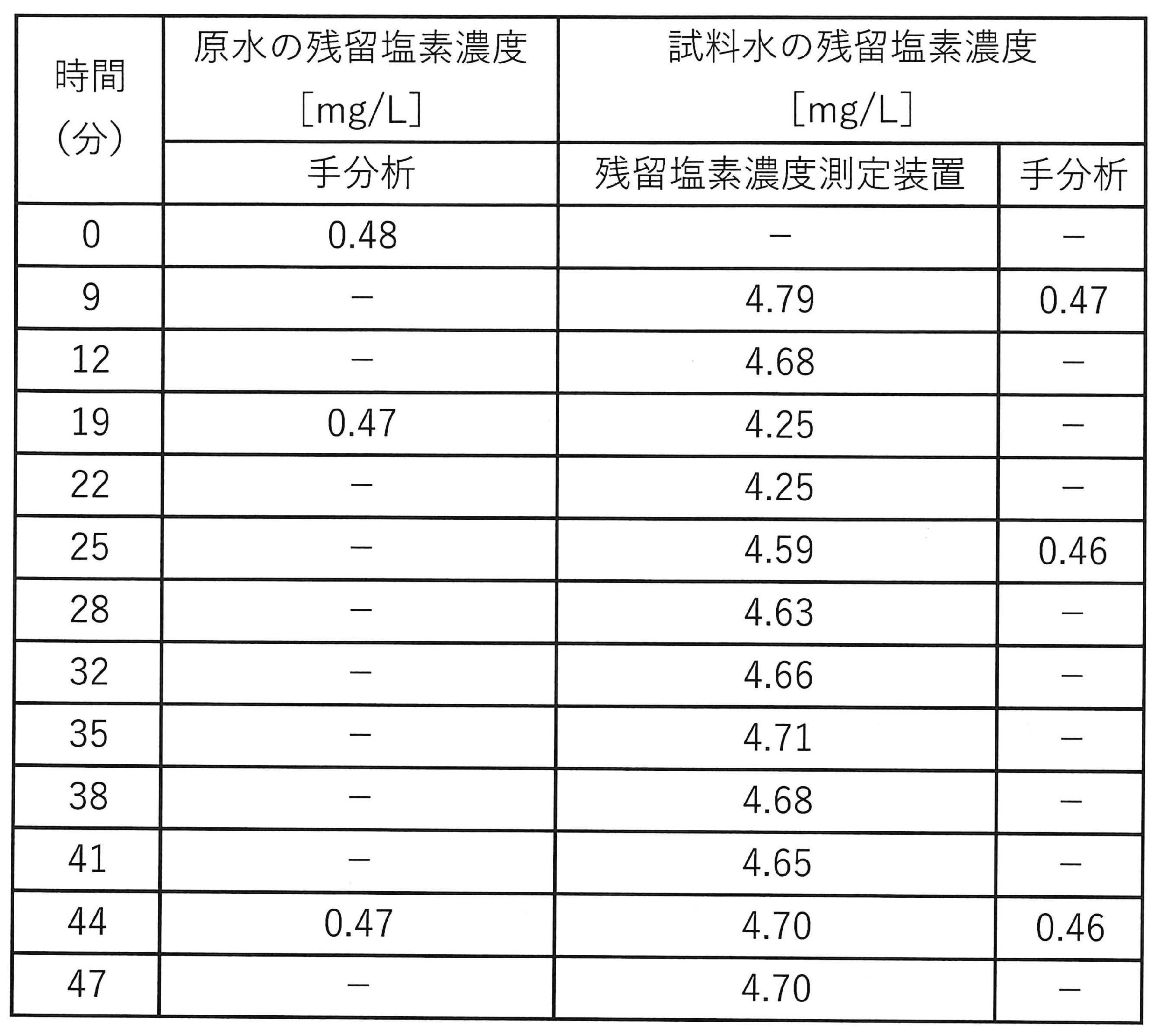
- sample water was prepared by diluting raw water with a residual chlorine concentration of 500 mg/L 100 times in a dilution device, and a measurement cell for 0.00 to 8.00 mg/L was used in a residual chlorine concentration measurement device. The residual chlorine concentration of the sample water was automatically measured.
- the tester manually collects the raw water and the sample water stored in the sample water storage unit, and measures the residual chlorine concentration of these for 0.00 to 2.00 mg / L. It was measured by the residual chlorine concentration measuring device using a cell. The procedure for concentration measurement will be described below.
- the residual chlorine concentration of the raw water in the raw water tank was measured by manual analysis.
- the water quality measuring device is operated, and after the start of operation, 9 minutes, 12 minutes, 19 minutes, 22 minutes, 25 minutes, 28 minutes, 32 minutes, 35 minutes, 38 minutes, 41 minutes, 44 minutes, and 47 minutes At the time point of 10 minutes, automatic measurement was performed using a residual chlorine concentration measuring device. Further, after the start of the operation, the raw water was sampled at 19 minutes and 44 minutes, and the sample water in the sample water reservoir was sampled at 9 minutes, 25 minutes, and 44 minutes. was measured by manual analysis.
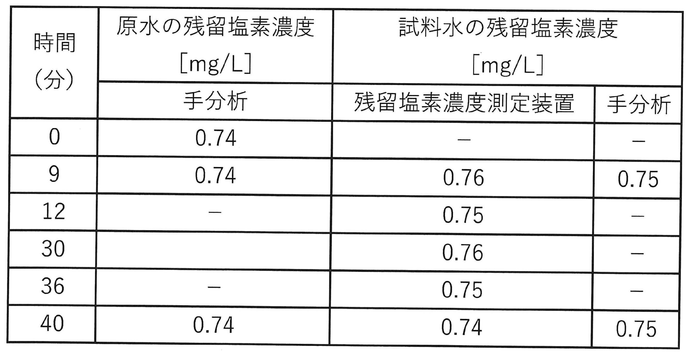
- the concentration of the sample water measured by the residual chlorine concentration measuring device was almost the same as the concentration measured by manual analysis. From this, it can be seen that the residual chlorine concentration measured by the water quality measuring device of the present invention is equivalent to the concentration measured by the conventional manual analysis.
- the present invention can also have the following forms.
- a dilution device for preparing sample water containing raw water and dilution water; a residual chlorine concentration measuring device for measuring the residual chlorine concentration of the sample water,
- the dilution device a container containing the sample water; a first liquid level detection unit that detects a first liquid level in the container; a second liquid level detection unit that detects a second liquid level in the container; a raw water injection unit that injects the raw water into the container until the first liquid level detection unit detects the first liquid level; a dilution water injection unit that injects the dilution water into the container to dilute the raw water until the second liquid level detection unit detects the second liquid level;
- a water quality measuring device for preparing sample water containing raw water and dilution water
- a residual chlorine concentration measuring device for measuring the residual chlorine concentration of the sample water
- the dilution device a container containing the sample water; a first liquid level detection unit that detects a first liquid level in the container
- the dilution device a discharge unit for discharging the sample water contained in the container until the first liquid level detection unit detects the first liquid level; After the discharge part discharges the sample water, the dilution water injection part injects the dilution water into the container until the second liquid level detection part detects the second liquid level, and the raw water
Landscapes
- Chemical & Material Sciences (AREA)
- Health & Medical Sciences (AREA)
- Life Sciences & Earth Sciences (AREA)
- General Health & Medical Sciences (AREA)
- Analytical Chemistry (AREA)
- Biochemistry (AREA)
- Physics & Mathematics (AREA)
- General Physics & Mathematics (AREA)
- Immunology (AREA)
- Pathology (AREA)
- Engineering & Computer Science (AREA)
- Food Science & Technology (AREA)
- Medicinal Chemistry (AREA)
- Investigating Or Analyzing Non-Biological Materials By The Use Of Chemical Means (AREA)
- Sampling And Sample Adjustment (AREA)
Abstract
Description
そこで、本発明は、高濃度の残留塩素を定量可能な装置を提供することを主目的とする。
原水及び希釈水を含む試料水を調製する希釈装置と、
前記試料水の残留塩素濃度を測定する残留塩素濃度測定装置と、を含み、
前記希釈装置が、
前記試料水が収容される容器と、
前記容器内の第1の液面を検知する第1の液面検知部と、
前記容器内の第2の液面を検知する第2の液面検知部と、
前記第1の液面検知部が前記第1の液面を検知するまで、前記容器に前記原水を注入する原水注入部と、
前記第2の液面検知部が前記第2の液面を検知するまで、前記容器に前記希釈水を注入し、前記原水の希釈を行う希釈水注入部と、
を備える、水質測定装置を提供する。
前記希釈装置が、
前記第1の液面検知部が前記第1の液面を検知するまで、前記容器に収容された前記試料水を排出する排出部を備え、
前記排出部が前記試料水を排出した後に、前記第2の液面検知部が前記第2の液面を検知するまで、前記希釈水注入部が前記容器に前記希釈水を注入し、前記原水の再希釈を行うものであってよい。
前記希釈装置において、前記原水の再希釈が2回以上行われてよい。
前記希釈装置が、前記容器内の前記試料水を循環させる循環部を備えていてよい。
前記残留塩素濃度測定装置が、試薬によって呈色した前記試料水の吸光度に基づいて前記試料水の残留塩素濃度を測定するものであってよい。
前記試薬が、N,N-ジエチル-1,4-フェニレンジアミン試薬であってよい。
前記原水の残留塩素濃度が、8mg/L超であってよい。
前記原水が、定置洗浄用の洗浄水であってよい。
希釈倍率X[倍]=AS/AR=(AR+AD)/AR
希釈倍率XY[倍]=XY+1

[1]
原水及び希釈水を含む試料水を調製する希釈装置と、
前記試料水の残留塩素濃度を測定する残留塩素濃度測定装置と、を含み、
前記希釈装置が、
前記試料水が収容される容器と、
前記容器内の第1の液面を検知する第1の液面検知部と、
前記容器内の第2の液面を検知する第2の液面検知部と、
前記第1の液面検知部が前記第1の液面を検知するまで、前記容器に前記原水を注入する原水注入部と、
前記第2の液面検知部が前記第2の液面を検知するまで、前記容器に前記希釈水を注入し、前記原水の希釈を行う希釈水注入部と、
を備える、水質測定装置。
[2]
前記希釈装置が、
前記第1の液面検知部が前記第1の液面を検知するまで、前記容器に収容された前記試料水を排出する排出部を備え、
前記排出部が前記試料水を排出した後に、前記第2の液面検知部が前記第2の液面を検知するまで、前記希釈水注入部が前記容器に前記希釈水を注入し、前記原水の再希釈を行う、[1]に記載の水質測定装置。
[3]
前記希釈装置において、前記原水の再希釈が2回以上行われる、[2]に記載の水質測定装置。
[4]
前記希釈装置が、前記容器内の前記試料水を循環させる循環部を備える、[1]~[3]のいずれか一つに記載の水質測定装置。
[5]
前記残留塩素濃度測定装置が、試薬によって呈色した前記試料水の吸光度に基づいて前記試料水の残留塩素濃度を測定する、[1]~[4]のいずれか一つに記載の水質測定装置。
[6]
前記試薬が、N,N-ジエチル-1,4-フェニレンジアミン試薬である、[5]に記載の水質測定装置。
[7]
前記原水の残留塩素濃度が、8mg/L超である、[1]~[6]のいずれか一つに記載の水質測定装置。
[8]
前記原水が、定置洗浄用の洗浄水である、[1]~[7]のいずれか一つに記載の水質測定装置。
Claims (8)
- 原水及び希釈水を含む試料水を調製する希釈装置と、
前記試料水の残留塩素濃度を測定する残留塩素濃度測定装置と、を含み、
前記希釈装置が、
前記試料水が収容される容器と、
前記容器内の第1の液面を検知する第1の液面検知部と、
前記容器内の第2の液面を検知する第2の液面検知部と、
前記第1の液面検知部が前記第1の液面を検知するまで、前記容器に前記原水を注入する原水注入部と、
前記第2の液面検知部が前記第2の液面を検知するまで、前記容器に前記希釈水を注入し、前記原水の希釈を行う希釈水注入部と、
を備える、水質測定装置。 - 前記希釈装置が、
前記第1の液面検知部が前記第1の液面を検知するまで、前記容器に収容された前記試料水を排出する排出部を備え、
前記排出部が前記試料水を排出した後に、前記第2の液面検知部が前記第2の液面を検知するまで、前記希釈水注入部が前記容器に前記希釈水を注入し、前記原水の再希釈を行う、請求項1に記載の水質測定装置。 - 前記希釈装置において、前記原水の再希釈が2回以上行われる、請求項2に記載の水質測定装置。
- 前記希釈装置が、前記容器内の前記試料水を循環させる循環部を備える、請求項1~3のいずれか一項に記載の水質測定装置。
- 前記残留塩素濃度測定装置が、試薬によって呈色した前記試料水の吸光度に基づいて前記試料水の残留塩素濃度を測定する、請求項1~4のいずれか一項に記載の水質測定装置。
- 前記試薬が、N,N-ジエチル-1,4-フェニレンジアミン試薬である、請求項5に記載の水質測定装置。
- 前記原水の残留塩素濃度が、8mg/L超である、請求項1~6のいずれか一項に記載の水質測定装置。
- 前記原水が、定置洗浄用の洗浄水である、請求項1~7のいずれか一項に記載の水質測定装置。
Priority Applications (3)
| Application Number | Priority Date | Filing Date | Title |
|---|---|---|---|
| US18/714,583 US20250027854A1 (en) | 2021-12-13 | 2022-10-20 | Water quality measurement device |
| CN202280069672.0A CN118103703A (zh) | 2021-12-13 | 2022-10-20 | 水质测定装置 |
| KR1020247013454A KR20240113749A (ko) | 2021-12-13 | 2022-10-20 | 수질 측정 장치 |
Applications Claiming Priority (2)
| Application Number | Priority Date | Filing Date | Title |
|---|---|---|---|
| JP2021-201385 | 2021-12-13 | ||
| JP2021201385A JP7331912B2 (ja) | 2021-12-13 | 2021-12-13 | 水質測定装置 |
Publications (1)
| Publication Number | Publication Date |
|---|---|
| WO2023112474A1 true WO2023112474A1 (ja) | 2023-06-22 |
Family
ID=86774440
Family Applications (1)
| Application Number | Title | Priority Date | Filing Date |
|---|---|---|---|
| PCT/JP2022/039050 Ceased WO2023112474A1 (ja) | 2021-12-13 | 2022-10-20 | 水質測定装置 |
Country Status (6)
| Country | Link |
|---|---|
| US (1) | US20250027854A1 (ja) |
| JP (1) | JP7331912B2 (ja) |
| KR (1) | KR20240113749A (ja) |
| CN (1) | CN118103703A (ja) |
| TW (1) | TW202326098A (ja) |
| WO (1) | WO2023112474A1 (ja) |
Families Citing this family (1)
| Publication number | Priority date | Publication date | Assignee | Title |
|---|---|---|---|---|
| JP7663114B1 (ja) * | 2023-11-08 | 2025-04-16 | 栗田工業株式会社 | 水質測定用希釈装置及び希釈方法 |
Citations (7)
| Publication number | Priority date | Publication date | Assignee | Title |
|---|---|---|---|---|
| JPS50137790A (ja) * | 1974-04-22 | 1975-11-01 | ||
| JPH05111630A (ja) * | 1991-10-23 | 1993-05-07 | Japan Organo Co Ltd | 濃厚液体の希釈装置 |
| JPH05180799A (ja) * | 1991-12-28 | 1993-07-23 | Kyoto Denshi Kogyo Kk | 残留塩素測定装置 |
| JPH09304248A (ja) * | 1996-05-10 | 1997-11-28 | Dkk Corp | 計量装置及び希釈装置 |
| JP2007093398A (ja) * | 2005-09-29 | 2007-04-12 | Miura Co Ltd | 残留塩素濃度の測定方法および測定装置 |
| JP2009024895A (ja) * | 2007-07-17 | 2009-02-05 | Miura Co Ltd | 水処理システム、及び冷却系循環水の処理方法 |
| JP2018080928A (ja) * | 2016-11-14 | 2018-05-24 | 日本電色工業株式会社 | 試料水希釈装置及び試料水希釈方法 |
-
2021
- 2021-12-13 JP JP2021201385A patent/JP7331912B2/ja active Active
-
2022
- 2022-10-20 KR KR1020247013454A patent/KR20240113749A/ko active Pending
- 2022-10-20 US US18/714,583 patent/US20250027854A1/en active Pending
- 2022-10-20 CN CN202280069672.0A patent/CN118103703A/zh active Pending
- 2022-10-20 WO PCT/JP2022/039050 patent/WO2023112474A1/ja not_active Ceased
- 2022-11-04 TW TW111142105A patent/TW202326098A/zh unknown
Patent Citations (7)
| Publication number | Priority date | Publication date | Assignee | Title |
|---|---|---|---|---|
| JPS50137790A (ja) * | 1974-04-22 | 1975-11-01 | ||
| JPH05111630A (ja) * | 1991-10-23 | 1993-05-07 | Japan Organo Co Ltd | 濃厚液体の希釈装置 |
| JPH05180799A (ja) * | 1991-12-28 | 1993-07-23 | Kyoto Denshi Kogyo Kk | 残留塩素測定装置 |
| JPH09304248A (ja) * | 1996-05-10 | 1997-11-28 | Dkk Corp | 計量装置及び希釈装置 |
| JP2007093398A (ja) * | 2005-09-29 | 2007-04-12 | Miura Co Ltd | 残留塩素濃度の測定方法および測定装置 |
| JP2009024895A (ja) * | 2007-07-17 | 2009-02-05 | Miura Co Ltd | 水処理システム、及び冷却系循環水の処理方法 |
| JP2018080928A (ja) * | 2016-11-14 | 2018-05-24 | 日本電色工業株式会社 | 試料水希釈装置及び試料水希釈方法 |
Also Published As
| Publication number | Publication date |
|---|---|
| JP2023087160A (ja) | 2023-06-23 |
| US20250027854A1 (en) | 2025-01-23 |
| JP7331912B2 (ja) | 2023-08-23 |
| CN118103703A (zh) | 2024-05-28 |
| TW202326098A (zh) | 2023-07-01 |
| KR20240113749A (ko) | 2024-07-23 |
Similar Documents
| Publication | Publication Date | Title |
|---|---|---|
| JP5772886B2 (ja) | 分析装置 | |
| CN106872452A (zh) | 一种游离氯在线分析仪和其使用方法 | |
| CN105738287B (zh) | 水质分析仪 | |
| JP2001296173A (ja) | 光学特性計測装置における被検溶液量確認方法、計測系制御方法および溶液濃度計測方法。 | |
| US20060104827A1 (en) | Method and apparatus for pumping and diluting a sample | |
| CN107271707A (zh) | 一种取样装置及使用该装置的进样装置、检测系统 | |
| CN104977265B (zh) | 一种水样中可溶性硫化物分析仪及分析方法 | |
| JP7331912B2 (ja) | 水質測定装置 | |
| US11788971B2 (en) | Test kit, test method, dispensing device | |
| WO2008112945A1 (en) | Fluid sampling system with an in-line probe | |
| CN203053982U (zh) | 管网余氯自动分析仪 | |
| CN110006699A (zh) | 水质在线分析高精度定量装置及定量方法 | |
| CN118883687A (zh) | 一种用于pH在线测量和校准的一体化装置及其使用方法 | |
| JP4775937B2 (ja) | 近赤外線分光器を利用したリソグラフィ工程用組成物の実時間制御システム及びその制御方法 | |
| CN217638293U (zh) | 一种基于光电传感器的水质监测稀释及加标装置 | |
| CN111521748A (zh) | 一种水质判定系统 | |
| JP7316898B2 (ja) | 監視システムおよび監視方法 | |
| CN110286196A (zh) | 一种用于现场快速、准确测定饮用水余氯的方法 | |
| CN1811456B (zh) | 果蔬消毒液检测方法及检测控制装置 | |
| CN209858552U (zh) | 一种在线cod水质监测仪用自动检定装置 | |
| CN205067357U (zh) | 一种水质在线间歇流动检测装置 | |
| CN106290343A (zh) | 总剩余氧化物在线实时检测装置及检测方法 | |
| TW202519862A (zh) | 水質測定用稀釋裝置及稀釋方法 | |
| CN219915370U (zh) | 水质检测装置以及水体处理系统 | |
| CN222939097U (zh) | 一种钾离子、钙离子和氯离子在线分析仪的流路系统 |
Legal Events
| Date | Code | Title | Description |
|---|---|---|---|
| 121 | Ep: the epo has been informed by wipo that ep was designated in this application |
Ref document number: 22907008 Country of ref document: EP Kind code of ref document: A1 |
|
| WWE | Wipo information: entry into national phase |
Ref document number: 202280069672.0 Country of ref document: CN |
|
| WWE | Wipo information: entry into national phase |
Ref document number: 18714583 Country of ref document: US |
|
| WWE | Wipo information: entry into national phase |
Ref document number: 11202402212V Country of ref document: SG |
|
| NENP | Non-entry into the national phase |
Ref country code: DE |
|
| 122 | Ep: pct application non-entry in european phase |
Ref document number: 22907008 Country of ref document: EP Kind code of ref document: A1 |