WO2023112253A1 - エレベータ制御装置、エレベータシステム、エレベータ制御方法、及びエレベータ制御プログラム - Google Patents
エレベータ制御装置、エレベータシステム、エレベータ制御方法、及びエレベータ制御プログラム Download PDFInfo
- Publication number
- WO2023112253A1 WO2023112253A1 PCT/JP2021/046510 JP2021046510W WO2023112253A1 WO 2023112253 A1 WO2023112253 A1 WO 2023112253A1 JP 2021046510 W JP2021046510 W JP 2021046510W WO 2023112253 A1 WO2023112253 A1 WO 2023112253A1
- Authority
- WO
- WIPO (PCT)
- Prior art keywords
- elevator
- door
- user
- elevator control
- control device
- Prior art date
- Legal status (The legal status is an assumption and is not a legal conclusion. Google has not performed a legal analysis and makes no representation as to the accuracy of the status listed.)
- Ceased
Links
Images






Classifications
-
- B—PERFORMING OPERATIONS; TRANSPORTING
- B66—HOISTING; LIFTING; HAULING
- B66B—ELEVATORS; ESCALATORS OR MOVING WALKWAYS
- B66B13/00—Doors, gates, or other apparatus controlling access to, or exit from, cages or lift well landings
- B66B13/02—Door or gate operation
- B66B13/14—Control systems or devices
-
- B—PERFORMING OPERATIONS; TRANSPORTING
- B66—HOISTING; LIFTING; HAULING
- B66B—ELEVATORS; ESCALATORS OR MOVING WALKWAYS
- B66B3/00—Applications of devices for indicating or signalling operating conditions of elevators
Definitions
- the present disclosure relates to an elevator control device, an elevator system, an elevator control method, and an elevator control program.
- Patent Document 1 proposes an elevator control device that controls elevators based on attributes (eg, tags) of passengers (ie, users) stored in a database.
- the elevator controller individually identifies elevator passengers based on images captured by cameras, weights captured by weight sensors, sounds collected by microphones, or a combination thereof, and identified passengers attributes are retrieved from the database.
- the elevator controller also determines the behavioral state (e.g., status) of the passenger, for example, if the status indicates disembarking and the tag indicates a wheelchair user, the elevator door open state time control, etc.
- the behavioral state e.g., status
- elevator passengers are individually identified, attributes of the identified passengers are acquired from a database, and the elevator is controlled based on the behavioral state and attributes of the identified passengers.
- the elevator is controlled based on the behavioral state and attributes of the identified passengers.
- the present disclosure provides an elevator control device, an elevator system, an elevator control method, and an elevator control program that enable door opening/closing control suitable for passengers based on at least one of sound waves and vibration of an elevator car. for the purpose.
- An elevator control device of the present disclosure includes an elevator car, a door driving device for opening and closing a door of the elevator car, an open/close detector for detecting whether the door is in an open state or a closed state, sound waves and the elevator. and a sensor for detecting at least one intensity of vibration of the car, wherein the open state of the door is detected by the sensor when the open/close detector detects the open state of the door.
- an acquisition unit that acquires intensity data indicating the time change of the intensity
- a determination unit that determines an attribute of a person getting in and out of the elevator car based on the intensity data
- a determination unit that determines the attribute of the door driving device based on the attribute.
- a control unit that performs control.
- An elevator system of the present disclosure includes an elevator car, a door driving device for opening and closing a door of the elevator car, an open/close detector for detecting whether the door is in an open state or a closed state, sound waves and the elevator car. and an elevator control device, wherein the elevator control device is detected by the sensor when the open state of the door is detected by the open/close detector an acquisition unit for acquiring strength data indicating a time change of the strength obtained from the above; a determination unit for determining an attribute of a person getting in and out of the elevator car based on the strength data; and the door driving device based on the attribute. and a control unit that controls
- the elevator control method of the present disclosure includes an elevator car, a door driving device for opening and closing a door of the elevator car, an open/close detector for detecting whether the door is open or closed, sound waves and the elevator. a sensor for detecting a physical quantity indicating at least one intensity of car vibration, wherein the open/close detector detects the open state of the door. a step of obtaining intensity data indicating a time change of the intensity detected by the sensor when the elevator car is in the air; determining an attribute of a person getting on and off the elevator car based on the intensity data; and a step of controlling the door driving device based on.
- door opening/closing control suitable for passengers can be performed based on at least one of sound waves and vibration of the elevator car.
- FIG. 1 is a diagram showing an example of hardware configuration of an elevator system and an elevator control device according to Embodiment 1;
- FIG. 1 is a schematic diagram showing the configuration of an elevator system according to Embodiment 1;
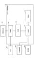
- FIG. 1 is a functional block diagram schematically showing the configuration of an elevator control device according to Embodiment 1;
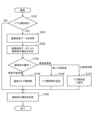
- FIG. 4 is a flow chart showing the operation of the elevator control device according to Embodiment 1;
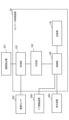
- FIG. 6 is a functional block diagram schematically showing the configuration of an elevator control device according to Embodiment 2;
- (A) to (D) are waveform diagrams showing the operation of the signal processing section of the elevator control device according to the second embodiment.
- FIG. 9 is a flow chart showing the operation of the determination unit of the elevator control device according to Embodiment 2;
- FIG. 11 is a functional block diagram schematically showing the configuration of an elevator control device according to Embodiment 3;
- 10 is a flow chart showing the operation of an elevator control device according to Embodiment 3;
- FIG. 9 is a flow chart showing the operation of the determination unit of the elevator control device according to Embodiment 2;
- FIG. 11 is a functional block diagram schematically showing the configuration of an elevator control device according to Embodiment 3;
- 10 is a flow chart showing the operation of an elevator control device according to Embodiment 3;
- FIG. 1 is a diagram showing an example of a hardware configuration of an elevator system and an elevator control device 10 according to Embodiment 1.
- FIG. 2 is a schematic diagram showing the configuration of the elevator system according to Embodiment 1.
- the configurations shown in FIGS. 1 and 2 are also configurations of elevator systems and elevator control devices 20, 30, 40, and 50 according to Embodiments 2 to 5, which will be described later.
- the elevator system according to Embodiment 1 has an elevator and an elevator control device 10 that controls the elevator.
- Elevator controller 10 controls one or more elevators.
- the elevator detects an elevator car 601, a lifting device 600 for raising and lowering the elevator car 601, a door driving device 500 for opening and closing a door 602 of the elevator car 601, and whether the door 602 is open or closed. It has an open/close detector 501 and a sensor 200 that detects the intensity of at least one of sound waves and vibration of the elevator car 601 .
- the elevator also has an input device 300 as a user operation unit and a display device 400 as an output device.
- the sensor 200 may be a microphone 201 that collects sound waves (i.e., sound) and detects the intensity of the sound waves, or a vibration sensor 202 that detects the intensity of vibrations of the elevator car 601 (e.g., floor or wall vibrations), or a microphone 201. and vibration sensor 202 .
- the microphone 201 and the vibration sensor 202 may be dedicated to determining attributes of passengers.
- the microphone 201 and the vibration sensor 202 are mounted for detecting abnormal sound or vibration during operation of the elevator lifting device 600 (that is, a microphone and vibration sensor for diagnosing elevator peripheral equipment). You may During the period in which the elevator is stopped and the elevator door 602 is open, it is not necessary to detect abnormal sounds or abnormal vibrations of the elevator device 600. There is no problem even if it is used for judgment.
- the input device 300 is a user interface for controlling the elevator control device 10, for example, a button or the like as an operation unit operated by an elevator passenger (also referred to as a "user"). Passengers are those who board the elevator car 601, those who exit the elevator car 601, or both those who board and those who exit.
- the display device 400 is an output device that presents information to passengers getting on and off the elevator.
- the display device 400 is provided on the wall surface of the hall 700 or the like to display the current floor of the elevator or the like, or a display provided in the elevator car 601 .
- the elevator control device 10 is composed of, for example, a processing circuit that controls the operation of the elevator.
- the processing circuit controls the operation (that is, raising and lowering) of the elevator car 601, the opening and closing of the door 602, and the like.
- the processing circuit may have a processor 11 , a main memory device 12 and a secondary memory device 13 .
- the processing circuitry may have a communication device 14 for communicating with other devices.
- the processor 11 is, for example, a CPU (Central Processing Unit), FPGA (Field Programmable Gate Array), or the like.
- the main storage device 12 is, for example, a memory such as a RAM (Random Access Memory).
- the auxiliary storage device 13 is a device having a storage medium for storing information, such as a ROM (Read Only Memory), HDD (Hard Disk Drive), or SSD (Solid State Drive).
- the main memory device 12 and the auxiliary memory device 13 store various data and software programs (eg, elevator control programs).
- FIG. 3 is a functional block diagram schematically showing the configuration of the elevator control device 10 according to Embodiment 1.
- the elevator control device 10 is a device capable of implementing the elevator control method according to the first embodiment.
- the elevator control device 10 acquires intensity data indicating temporal changes in intensity (for example, sound wave intensity or vibration intensity) detected by the sensor 200 when the open/close detector 501 detects the open state of the door 602 .
- It has an acquisition unit 120, a determination unit 130 that determines the attributes of passengers getting on and off the elevator car 601 based on strength data, and a control unit 140 that controls the door driving device 500 based on the attributes of the passengers.
- Elevator controller 10 is, for example, a computer.
- the elevator control device 10 may have an open/close detector 501 which is a determination circuit for detecting opening/closing of the door 602 by detecting current.
- a part or all of the acquisition unit 120, the determination unit 130, and the control unit 140 may be implemented by a processing circuit.
- Sensor data (for example, sound wave intensity data, vibration intensity data, or both) acquired by the sensor 200 is recorded in the main storage device 12 or the auxiliary storage device 13 .
- the open/close detector 501 is a device that determines whether the door 602 provided in the elevator car 601 is open or closed.
- the open/close detector 501 may be, for example, a device provided in the door 602 to detect the open state and closed state of the door 602 .
- the open/close detector 501 has, for example, a switch and a detection circuit.
- the open/close detector 501 may be a device comprising a current sensor. In this case, the open/close detector 501 detects the current in the cable that transmits the control signal for opening and closing the door 602, and determines whether the door 602 is open or closed based on this current.
- the acquiring unit 120 acquires the time change of the intensity of the sound signal corresponding to the sound wave detected by the microphone 201 as the sensor 200 when the opening/closing detector 501 detects that the door 602 is open. is acquired (sound wave intensity data in the first embodiment).
- the determination unit 130 determines attributes of passengers getting on and off the elevator car 601 based on the sound wave intensity data acquired by the acquisition unit 120 .
- the determination unit 130 determines whether the passenger is a vehicle non-user who does not use the vehicle or a vehicle user who uses the vehicle. Attribute determination processing to be determined is performed.
- the vehicle is a wheelchair and a trolley.
- the truck is, for example, four-wheeled. however.
- the vehicle may be a wheelchair only. Alternatively, the vehicle may have only a bogie.
- the determination unit 130 determines whether the person getting on and off the elevator is a non-vehicle user or a wheelchair user using a wheelchair as a vehicle. Further, in the attribute determination process, the determination unit 130 determines whether the person getting on and off the vehicle is a vehicle non-user or a truck user using a truck as a vehicle. In the attribute determination process, the determination unit 130 determines whether the person getting on and off the vehicle is a vehicle non-user, a wheelchair user using a wheelchair as a vehicle, or a truck using a truck as a vehicle. Determine whether the user is a user.
- the determination unit 130 performs attribute determination processing using, for example, the following method.
- the determination unit 130 obtains the maximum signal level of the sound wave intensity data input while the elevator door 602 is open. At this time, a digital filter may be applied to the sound wave intensity data to extract only a specific frequency band. Alternatively, the determining unit 130 sets the time window length and the time to apply the time window in advance, and calculates the signal level for each time window from means for calculating the signal level such as the root mean square (that is, the effective value). may be asked for. If the maximum signal level obtained from the sound wave intensity data is equal to or higher than a predetermined threshold, the determination unit 130 determines that the passenger is a wheelchair user or a cart user. It is determined that the vehicle is a non-user.
- the determination unit 130 may be an estimation device that estimates the attributes of passengers using a learned model generated by machine learning.
- the determination unit 130 determines the operation sound when the non-user of the vehicle gets on and off the elevator car 601 on foot, the operation sound when the wheelchair user gets on and off the elevator car 601, and the operation sound when the trolley user gets on and off the elevator car 601.
- the operation sounds generated when the vehicle is engaged are acquired in advance, the features of these operation sounds are learned by machine learning, and a learned model is generated in advance.
- a class classifier using SVM (Support Vector Machine) or GMM (Gaussian Mixture Model) can be used as a machine learning algorithm.
- other class classifiers based on deep learning may be used as machine learning algorithms.
- the control unit 140 controls the door drive device 500 based on the attributes determined by the determination unit 130 . For example, if the determination unit 130 determines that the passenger does not use the vehicle, the determination unit 130 keeps the door open time as the normal door opening/closing time (preset standard opening time). If the user is determined to be a wheelchair user or a trolley user, the door opening time is extended longer than the standard opening time. To extend the door open state, keep the door open for a longer time than the standard open time, or keep the door open until the close button to close the door is pressed. There are cases.
- the storage unit 141 records the door control result, the attributes of the person getting on and off, and the alighting floor input by the input device 300 when the person getting on and off is a vehicle user. As a result, when the passenger is a vehicle user, the opening/closing speed of the door can be changed from the normal speed when the target floor is reached. When getting off the vehicle, the attribute of the person getting on and off is determined in the same way as when getting on the vehicle.
- the storage unit 141 is a storage device of a device that can communicate via the main storage device 12, the auxiliary storage device 13, or the communication device 14 in FIG. , the door control result, the attributes of the person getting on and off, and the alighting floor input by the input device 300 are recorded.
- the current door control state is displayed on the display device 400 along with the door control. For example, when it is detected that the person getting on and off is a vehicle user, it is displayed on the display on the hall 700 side or in the elevator car 601 that the door opening time is longer than usual.
- FIG. 4 is a flow chart showing the operation of the elevator control device 10 according to the first embodiment.
- the open/close detector 501 detects whether or not the door 602 of the elevator is open by detecting opening and closing operations of the door 602 (step S101). If door 602 is open (YES in step S101), the process proceeds to step S102, and if door 602 is closed (NO in step S101), the process ends.
- step S101 If the door 602 is open (YES in step S101), the acquisition unit 120 acquires sound wave intensity data from the microphone 201 (step S102), and the determination unit 130 performs attribute determination for determining attributes of passengers getting on and off the elevator. Processing is performed (step S103).
- step S104 The process is branched based on the determination result of the attributes of the passengers in the determination unit 130 (step S104). If the person getting on and off the elevator does not use the vehicle, the process proceeds to step S105, and the control unit 140 controls opening and closing of the door 602 during the normal door opening time (step S105). When it is determined that the person getting on and off the elevator is a wheelchair user, the process proceeds to step S106, and the control unit 140 controls the opening and closing of the door 602 so as to extend the door opening time (step S106). If it is determined that the person getting on and off is a bogie user, the process proceeds to step S107, and the control unit 140 keeps the door 602 in the open state until the door closing operation is performed (for example, until the door close button is pressed). (step S107).
- control unit 140 records the control result of the door 602, the attributes of the person getting on and off, and the alighting floor input by the input device 300 when the person getting on and off is the vehicle user in the storage unit 141 (step 108). .
- the passenger is a wheelchair user or a cart user who takes a relatively long time to get on and off, or walks to get on and off without using a vehicle. It is possible to determine whether or not the person is a non-user of the vehicle, and control the opening and closing of the door 602 according to the determination result so that the opening time of the door 602 is suitable for passengers getting on and off. As a result, elevator users can use the elevator with greater peace of mind.
- FIG. 5 is a functional block diagram schematically showing the configuration of elevator control device 20 according to the second embodiment.
- the same reference numerals as those shown in FIG. 3 are attached to the same or corresponding configurations as those shown in FIG.
- the elevator control device 20 is a device capable of implementing the elevator control method according to the second embodiment.
- the elevator control device 20 according to Embodiment 2 is similar to that of Embodiment 1 in that the determination unit 150 includes a signal processing unit 151, a local maximum/minimum value calculation unit 152, a difference determination unit 153, and a time difference determination unit 154. is different from the elevator control device 10 according to Except for this point, the configuration of the elevator control device 20 according to the second embodiment is the same as the configuration of the elevator control device 10 according to the first embodiment.
- FIGS. 6A to 6D are waveform diagrams showing the operation of the signal processing section 151 of the elevator control device 20 according to Embodiment 2.
- FIG. FIG. 6A shows sound wave intensity data 1001 to which signal processing is not applied and which is input to the signal processing unit 151 .
- FIG. 6B shows sound wave intensity data 1002 in which the frequency components of the footsteps of the trolley user, wheelchair user, and non-vehicle user are extracted by applying the processing by the bandpass filter of the signal processing unit 151.
- FIG. 6(C) shows the root mean square value 1003 calculated for each time window with respect to the sound wave intensity data 1002 of FIG. 6(B) by the signal processing unit 151 .
- FIG. 6(D) shows a value 1004 obtained by smoothing the value 1003 shown in FIG. 6(C) with a smoothing filter.
- a smoothing filter is, for example, a Gaussian filter.
- FIG. 7(A) and (B) are waveform diagrams showing the operation of the maximum/minimum value calculator 152 of the elevator control device 20 according to the second embodiment.
- the maximum value/minimum value calculation unit 152 calculates the maximum value and the minimum value for the value 1004 that has been smoothed by the signal processing unit 151 .
- FIG. 7B shows the result 1005 of calculating the maximum and minimum values for the value 1004 .
- white circles indicate maximum values and black circles indicate minimum values.
- the calculated maximum and minimum values are stored as a table in the storage unit 141 for each corresponding time.
- FIG. 8 is a diagram showing the local maximum value, the local minimum value, the time [s], the signal level [dB], and the difference [dB] between adjacent local maximum values and local minimum values in FIG. 7(B) in tabular form. be.
- the difference determination unit 153 determines whether or not the passenger is a trolley user based on the difference [dB] in the table of FIG.
- a threshold TH for the signal level difference is determined in advance, and if there are two or more locations where the difference when changing from the minimum value to the maximum value exceeds this threshold TH, the time difference determination unit 154 performs further processing. I do. If there is only one place where the threshold value TH is exceeded, it is determined that the passenger is a wheelchair user. If there is no location exceeding the threshold TH, it is determined that the person getting on and off the vehicle is a person who does not use the vehicle (that is, a person who gets on and off on foot). Wheelchairs and trolleys both have four wheels, which are the same. ).
- the time difference determination unit 154 obtains the time difference ⁇ t when there are two or more locations where the threshold value TH of the signal level difference predetermined by the difference determination unit 153 is exceeded.
- the time difference determination unit 154 determines that the person getting on and off the vehicle is a bogie user when the time difference ⁇ t is within a predetermined range, that is, Y seconds or more and Z seconds or less (Z>Y).
- Y seconds or more and Z seconds or less Z>Y.
- the front wheels and rear wheels of the truck are separated to some extent, and the sound when each of them passes through the gap between the elevator car 601 and the landing 700 takes only the time to move the truck, so Y seconds and Z seconds are set appropriately. By doing so, the bogie user is detected.
- the control unit 140 changes the door open time according to the attributes of the passengers determined by the determination unit 150 . For example, when the determination unit 150 determines that the passenger is a non-user of the vehicle, the control unit 140 determines that the passenger is a wheelchair user by adopting the normal duration of the door open state. If so, apply a longer door open duration than normal. Further, when it is determined that the person getting on and off is a bogie user, the control unit 140 switches to, for example, an extended open state in which the door is kept open until the door close button is pressed.
- FIG. 9 is a flow chart showing the operation of the determination unit 150 of the elevator control device 20 according to the second embodiment.
- the signal processing unit 151 applies processing using a bandpass filter to the sound wave intensity data provided from the acquisition unit 120 (step S201).
- the signal processing unit 151 calculates the root mean square of sound wave intensity data for each time window with respect to the signal that has passed through the bandpass filter (step S202).
- the signal processing unit 151 applies root-mean-square smoothing processing (step S203).
- the maximum value/minimum value calculation unit 152 calculates the maximum value and the minimum value for the smoothed value (step S204).
- the local maximum value/minimum value calculation unit 152 calculates the difference between the local maximum value and the local minimum value adjacent in time series (step S205).
- the difference determination unit 153 determines whether there are two or more locations where the difference calculated in step S205 is equal to or greater than the threshold TH, that is, +X [dB] (step S206). In step S206, if the number of locations where the difference is +X [dB] or more is less than two, the difference determination unit 153 determines whether or not there is one location where the difference is +X [dB] or more (step S207). ). When the difference is +X [dB] or more at 0 locations, the difference determination unit 153 determines that the passenger does not use the cart (step S211). If there is one location where the difference is +X [dB] or more, the difference determination unit 153 determines that the passenger is in a wheelchair (step S210).
- step S206 if there are two or more locations where the difference is +X [dB] or more, the time difference determination unit 154 calculates the time difference between the time of the maximum value and the time of the minimum value for each location (step S208). If at least one of the two or more calculated time differences is within a predetermined time range (that is, a range of Y seconds or more and Z seconds or less), the time difference determination unit 154 determines that the passenger It is determined that the user is the cart user (step S209). If any of the two or more calculated time differences is out of a predetermined time range (that is, the range of Y seconds or more and Z seconds or less), the time difference determination unit 154 determines that the passenger is a wheelchair user. It is determined that there is (step S210).
- the determination unit 150 determines that the person getting on and off the vehicle is a vehicle non-user when there is no place where the difference is greater than the predetermined threshold value TH. In addition, when there is one place where the difference is larger than the predetermined threshold value TH, the determination unit 150 determines that the passengers include a wheelchair user. In addition, the determination unit 150 determines which of the two or more locations where the difference is greater than the predetermined threshold TH and the time difference between two adjacent locations among the locations where the difference is greater than the predetermined threshold. If one or more are within a predetermined time range, it is determined that the person getting on and off includes a trolley user.
- the determining unit 150 determines that there are two or more locations where the difference is greater than the predetermined threshold TH and the time difference between two adjacent locations among the locations where the difference is greater than the predetermined threshold is is outside the predetermined time range, the passengers are determined to include wheelchair users.
- the determination unit 150 includes the signal processing unit 151, the local maximum/minimum value calculation unit 152, the difference determination unit 153, and the time difference determination unit 154.
- the threshold value By setting a threshold value, it is possible to determine the attributes of passengers even when machine learning is not used. Therefore, door opening/closing control suitable for passengers can be performed.
- FIG. 10 is a functional block diagram schematically showing the configuration of elevator control device 30 according to the third embodiment.
- the same reference numerals as those shown in FIG. 3 are attached to the same or corresponding configurations as those shown in FIG.
- the elevator control device 30 is a device capable of implementing the elevator control method according to the third embodiment.
- the acquisition unit 120 acquires vibration intensity data corresponding to the vibration of the elevator car 601 detected by the vibration sensor 202 as the sensor 200, and the determination unit 160 detects the vibration. It is different from the elevator control device 10 according to the first embodiment in that the attribute of the person getting on and off the elevator car 601 is determined based on the intensity data. Except for this point, the configuration of the elevator control device 30 according to the third embodiment is the same as the configuration of the elevator control device 10 according to the first embodiment.
- the determination unit 160 determines the attribute of the person getting on and off the elevator car 601 from the vibration intensity data. For example, the determination unit 160 applies FFT (Fast Fourier Transform) to the vibration intensity data for each time window to calculate a spectrogram in which the vertical axis indicates frequency, the horizontal axis indicates time, and the gradation indicates the signal level. Alternatively, the determination unit 160 acquires a calculated value similar to the spectrogram by wavelet analysis. Thereafter, determination section 160 checks whether the signal level is equal to or higher than a predetermined threshold for each predetermined frequency band. For example, when there is a signal level peak in the frequency band of 7 Hz to 12 Hz, the determination unit 160 determines that the passenger is a non-user of the vehicle.
- FFT Fast Fourier Transform
- the determination unit 160 determines that the person getting on and off is a bogie user. For example, if the signal level has a maximum value near 10 Hz and the signal level is equal to or higher than a predetermined threshold for a predetermined period of time or longer, the determination unit 160 determines that the passenger is in a wheelchair. Determined to be the user.
- the determination unit 160 may perform determination using a learned model generated in advance by machine learning when determining the attributes of passengers getting on and off.
- FIG. 11 is a flow chart showing the operation of the elevator control device 30 according to the third embodiment.
- the same reference numerals as those shown in FIG. 4 are assigned to the same or corresponding processes as those shown in FIG.
- the operation of the elevator control device 30 according to the third embodiment differs from the operation of the elevator control device 10 according to the first embodiment in the processing of steps S301 and S302. Other than this point, the operation of the elevator control device 30 according to the third embodiment is the same as the operation of the elevator control device 10 according to the first embodiment.
- the acquiring unit 120 acquires vibration intensity data in step S301.
- the determination unit 150 determines the attribute of the person getting on and off the elevator car 601 based on the vibration intensity data.
- the determination result of the attributes of the passenger based on the vibration intensity data is used.
- the attribute of the passenger is determined based on the sound wave intensity data collected by the microphone 201, but the sound wave intensity data is susceptible to disturbance from the surrounding environment.
- vibration intensity data is less susceptible to disturbances from the surrounding environment.
- attributes of passengers can be determined with relatively high accuracy. Therefore, door opening/closing control suitable for passengers can be performed.
- FIG. 12 is a functional block diagram schematically showing the configuration of elevator control device 40 according to the fourth embodiment. 12, the same reference numerals as those shown in FIG. 3 or FIG. 10 are attached to the same or corresponding configurations as those shown in FIG. 3 or FIG.
- the elevator control device 40 is a device capable of implementing the elevator control method according to the fourth embodiment.
- the elevator control device 40 according to Embodiment 4 is similar to the elevator control device 10 or 30 different.
- the sound determination unit 171 determines the attribute of the person getting on and off the elevator car 601 based on the sound wave intensity data, similarly to the determination unit 130 in FIG.
- Vibration determination unit 172 determines the attribute of the person getting on and off elevator car 601 based on the vibration intensity data, similar to determination unit 160 in FIG. 10 .
- the determination result integration unit 173 integrates the determination results based on the determination result by the sound determination unit 171 and the determination result by the vibration determination unit 172, and outputs the integrated determination result. Except for this point, the configuration of the elevator control device 40 according to the fourth embodiment is the same as the configuration of the elevator control device 10 or 30 according to the first or third embodiment.
- the sound determination unit 171 determines whether the person getting on and off the elevator car 601 is a non-vehicle user, a wheelchair user, or a bogie user, based on the sound wave intensity data. For example, the determination result is provided as a score (that is, a numerical value) indicating the possibility of being a non-vehicle user, a wheelchair user, or a cart user.
- a score that is, a numerical value
- the vibration determination unit 172 determines whether the person getting on and off the elevator car 601 is a non-vehicle user, a wheelchair user, or a bogie user, based on the vibration intensity data. For example, the determination result is provided as a score (that is, a numerical value) indicating the possibility of being a non-vehicle user, a wheelchair user, or a cart user.
- a score that is, a numerical value
- the determination result integration unit 173 integrates the determination results by calculating the average of the score provided by the sound determination unit 171 and the score provided by the vibration determination unit 172, for example.
- the average may be a weighted average of the score provided by the sound determiner 171 and the score provided by the vibration determiner 172 .
- the determination unit 170 may perform determination using a learned model generated in advance by machine learning when determining the attributes of passengers getting on and off.
- FIG. 13 is a flow chart showing the operation of the elevator control device 40 according to the fourth embodiment.
- the same reference numerals as those shown in FIG. 4 or 11 are attached to the same or corresponding processing as those shown in FIG. 4 or FIG.
- the operation of the elevator control device 40 according to the fourth embodiment differs from the operation of the elevator control device 10 or 30 according to the first or third embodiment in the processing of steps S401 to S403.
- the operation of the elevator control device 40 according to the fourth embodiment is the same as the operation of the elevator control device 10 or 30 according to the first or third embodiment.
- step S401 the acquisition unit 120 acquires sound wave intensity data and vibration intensity data.
- the sound determination unit 171 determines the attribute of the person getting on and off the elevator car 601 based on the sound wave intensity data.
- the vibration determination unit 172 determines the attribute of the person getting on and off the elevator car 601 based on the vibration intensity data.
- the determination result integration unit 173 integrates the determination result by the sound determination unit 171 and the determination result by the vibration determination unit 172, and outputs the integrated determination result.
- the determination unit 170 determines the attribute of the passenger to be the first attribute based on the sound wave intensity data, determines the attribute of the passenger to be the second attribute based on the vibration intensity data, and the control unit 140 , the door drive device 500 is controlled based on the determination result obtained by integrating the first attribute and the second attribute.
- an integrated judgment result is used that integrates the judgment result of the attributes of the passenger based on the sound wave intensity data and the judgment result of the attributes of the passenger based on the vibration intensity data. , it is possible to improve the determination accuracy of the attribute of the passenger, as compared with the case where only one of the sound wave intensity data and the vibration intensity data is used. Therefore, it is possible to perform opening/closing control of the door suitable for the passenger.
- FIG. 14 is a functional block diagram schematically showing the configuration of elevator control device 50 according to the fifth embodiment.
- the elevator control device 50 is a device capable of implementing the elevator control method according to the fifth embodiment.
- Elevator control device 50 according to Embodiment 5 differs from elevator control device 40 according to Embodiment 4 in that determination unit 180 includes data integration unit 181 and integrated data determination unit 182 .
- the data integration unit 181 integrates the sound wave intensity data and the vibration intensity data acquired by the acquisition unit 120 to generate integrated data.
- the integrated data determination unit 182 determines the attribute of the person getting on and off the elevator car 601 based on the integrated data generated by the data integration unit 181 . Except for this point, the configuration of the elevator control device 50 according to the fifth embodiment is the same as the configuration of the elevator control device 40 according to the fourth embodiment.
- the data integration unit 181 integrates, for example, the frequency spectrum extracted from the sound wave intensity data and the frequency spectrum extracted from the vibration intensity data. Specifically, the data integration unit 181 first determines the number and intensity (ie, vertical axis) of frequency channels (ie, horizontal axis) in the frequency spectrum extracted from the sound wave intensity data, and the frequency channel extracted from the vibration intensity data. (ie, horizontal axis) and intensity (ie, vertical axis) are adjusted to a predetermined ratio (eg, 1). Next, the data integration unit 181 arranges the frequency spectrum of the sound wave intensity data in the odd-numbered channels and the frequency spectrum of the vibration intensity data in the even-numbered channels to generate an integrated frequency spectrum, thereby performing data integration. .
- the data integration method is not limited to the above example.
- the data integrating unit 181 extracts feature quantities (for example, maximum and minimum values and their frequency channels) extracted from sound wave intensity data and feature quantities extracted from vibration intensity data, for example, maximum and minimum values, and their frequency channels) on a common frequency axis.
- the integrated data determination unit 182 uses the integrated data integrated by the data integration unit 181 to determine the attributes of the passengers. This determination may be a determination using a learned model generated in advance by machine learning.
- FIG. 15 is a flow chart showing the operation of the elevator control device 50 according to the fifth embodiment.
- the same or corresponding processes as those shown in FIG. 12 are given the same reference numerals as those shown in FIG.
- the operation of the elevator control device 50 according to the fifth embodiment differs from the operation of the elevator control device 40 according to the fourth embodiment in the processing of steps S501 to S503.
- the operation of the elevator control device 50 according to the fifth embodiment is the same as the operation of the elevator control device 40 according to the fourth embodiment.
- the acquisition unit 120 acquires sound wave intensity data and vibration intensity data in step S501.
- the data integration unit 181 integrates the sound wave intensity data and the vibration intensity data acquired by the acquisition unit 120 .
- the integrated data determination unit 182 determines the attribute of the passenger based on the integrated data.
- the attribute of the passenger is determined based on the integrated data obtained by integrating the sound wave intensity data and the vibration intensity data. Compared with the case of using only one of the data, it is possible to improve the determination accuracy of the attribute of the passenger. Therefore, door opening/closing control suitable for passengers can be performed.
- Elevator control device 11 Processor, 12 Main storage device, 13 Auxiliary secondary storage device, 14 Communication device, 120 Acquisition unit, 130, 150, 160, 170, 180 Judgment unit, 140 Control unit , 151 signal processing unit, 152 local maximum/minimum value calculation unit, 153 difference determination unit, 154 time difference determination unit, 171 sound determination unit, 172 vibration determination unit, 173 determination result integration unit, 181 data integration unit, 182 integrated data determination Section 141 Storage Section 200 Sensor 201 Microphone 202 Vibration Sensor 300 Input Device 400 Display Device 500 Door Drive Device 501 Opening/Closing Detector 600 Lifting Device 601 Elevator Car 602 Door.
Landscapes
- Engineering & Computer Science (AREA)
- Automation & Control Theory (AREA)
- Elevator Door Apparatuses (AREA)
- Indicating And Signalling Devices For Elevators (AREA)
Abstract
エレベータ制御装置(10)は、エレベータかご(601)と、エレベータかごのドア(602)を開閉するドア駆動装置(500)と、ドアが開状態であるか閉状態であるかを検出する開閉検出器(501)と、音波及びエレベータかごの振動の少なくとも一方の強度を検出するセンサ(200)とを有するエレベータ、を制御する。エレベータ制御装置(10)は、開閉検出器(501)によってドアの開状態が検出されているときに、センサ(200)によって検出された強度の時間変化を示す強度データを取得する取得部(120)と、強度データに基づいてエレベータかご(601)に乗降する乗降者の属性を判定する判定部(130)と、属性に基づいてドア駆動装置(500)の制御を行う制御部(140)とを有する。
Description
本開示は、エレベータ制御装置、エレベータシステム、エレベータ制御方法、及びエレベータ制御プログラムに関する。
特許文献1は、データベースに記憶された乗客(すなわち、ユーザ)の属性(例えば、タグ)に基づいてエレベータを制御するエレベータ制御装置を提案している。このエレベータ制御装置は、カメラ撮影で取得された画像、重量センサで取得された重量、マイクで収集された音声、又はこれらの組み合わせに基づいて、エレベータの乗客を個々に識別し、識別された乗客の属性をデータベースから取得している。また、このエレベータ制御装置は、乗客の行動状態(例えば、ステータス)を判定し、例えば、「ステータスが降車中を示し、かつ、タグが車いすのユーザを示す」場合に、エレベータのドアの開状態の時間の制御などを行う。
上記従来のエレベータ制御装置では、エレベータの乗客を個々に識別し、識別された乗客の属性をデータベースから取得し、識別された乗客の行動状態と属性とに基づいてエレベータの制御を行っている。しかし、カメラが設置されていないエレベータでは、乗客を個々に識別することができず、識別された乗客の属性をデータベースから取得することができないので、乗客の属性に基づくエレベータの制御ができなかった。
本開示は、音波及びエレベータかごの振動の少なくとも一方に基づいて乗降者に適したドアの開閉制御を行うことを可能にするエレベータ制御装置、エレベータシステム、エレベータ制御方法、及びエレベータ制御プログラムを提供することを目的とする。
本開示のエレベータ制御装置は、エレベータかごと、前記エレベータかごのドアを開閉するドア駆動装置と、前記ドアが開状態であるか閉状態であるかを検出する開閉検出器と、音波及び前記エレベータかごの振動の少なくとも一方の強度を検出するセンサとを有するエレベータ、を制御するエレベータ制御装置であって、前記開閉検出器によって前記ドアの開状態が検出されているときに、前記センサによって検出された前記強度の時間変化を示す強度データを取得する取得部と、前記強度データに基づいて前記エレベータかごに乗降する乗降者の属性を判定する判定部と、前記属性に基づいて前記ドア駆動装置の制御を行う制御部と、を有することを特徴とする。
本開示のエレベータシステムは、エレベータかごと、前記エレベータかごのドアを開閉するドア駆動装置と、前記ドアが開状態であるか閉状態であるかを検出する開閉検出器と、音波及び前記エレベータかごの振動の少なくとも一方の強度を検出するセンサと、エレベータ制御装置と、を有し、前記エレベータ制御装置は、前記開閉検出器によって前記ドアの開状態が検出されているときに、前記センサによって検出された前記強度の時間変化を示す強度データを取得する取得部と、前記強度データに基づいて前記エレベータかごに乗降する乗降者の属性を判定する判定部と、前記属性に基づいて前記ドア駆動装置の制御を行う制御部と、を有することを特徴とする。
本開示のエレベータ制御方法は、エレベータかごと、前記エレベータかごのドアを開閉するドア駆動装置と、前記ドアが開状態であるか閉状態であるかを検出する開閉検出器と、音波及び前記エレベータかごの振動の少なくとも一方の強度を示す物理量を検出するセンサとを有するエレベータ、を制御するエレベータ制御装置によって実行されるエレベータ制御方法であって、前記開閉検出器によって前記ドアの開状態が検出されているときに、前記センサによって検出された前記強度の時間変化を示す強度データを取得するステップと、前記強度データに基づいて前記エレベータかごに乗降する乗降者の属性を判定するステップと、前記属性に基づいて前記ドア駆動装置の制御を行うステップと、を有することを特徴とする。
本開示によれば、音波及びエレベータかごの振動の少なくとも一方に基づいて乗降者に適したドアの開閉制御を行うことができる。
以下に、実施の形態に係るエレベータ制御装置、エレベータシステム、エレベータ制御方法、及びエレベータ制御プログラムを、図面を参照しながら説明する。以下の実施の形態は、例にすぎず、実施の形態を適宜組み合わせること及び各実施の形態を適宜変更することが可能である。
《実施の形態1》
図1は、実施の形態1に係るエレベータシステム及びエレベータ制御装置10のハードウェア構成の例を示す図である。また、図2は、実施の形態1に係るエレベータシステムの構成を示す概略図である。なお、図1及び図2に示される構成は、後述される実施の形態2から5に係るエレベータシステム及びエレベータ制御装置20、30、40、50の構成でもある。
図1は、実施の形態1に係るエレベータシステム及びエレベータ制御装置10のハードウェア構成の例を示す図である。また、図2は、実施の形態1に係るエレベータシステムの構成を示す概略図である。なお、図1及び図2に示される構成は、後述される実施の形態2から5に係るエレベータシステム及びエレベータ制御装置20、30、40、50の構成でもある。
実施の形態1に係るエレベータシステムは、エレベータと、エレベータを制御するエレベータ制御装置10とを有している。エレベータ制御装置10は、1台又は複数台のエレベータを制御する。エレベータは、エレベータかご601と、エレベータかご601を昇降させる昇降装置600と、エレベータかご601のドア602を開閉するドア駆動装置500と、ドア602が開状態であるか閉状態であるかを検出する開閉検出器501と、音波及びエレベータかご601の振動の少なくとも一方の強度を検出するセンサ200とを有している。また、エレベータは、ユーザ操作部である入力装置300と、出力装置としての表示装置400とを有している。
センサ200は、音波(すなわち、音)を収集して音波の強度を検出するマイク201、又はエレベータかご601の振動(例えば、床又は壁の振動)の強度を検出する振動センサ202、又はマイク201及び振動センサ202の両方、を有している。マイク201及び振動センサ202は、乗降者の属性の判定に専用のものであってもよい。ただし、マイク201及び振動センサ202は、エレベータの昇降装置600の動作時における異常音又は異常振動の検出用として搭載されているもの(すなわち、エレベータ周辺機器の診断用のマイク及び振動センサ)を利用してもよい。エレベータの昇降動作が停止しており、エレベータのドア602が開状態である期間は、昇降装置600の異常音又は異常振動の検出が不要であり、マイク201及び振動センサ202を乗降者の属性の判定用に用いても、問題は生じない。
入力装置300は、例えば、エレベータの乗降者(「ユーザ」ともいう。)によって操作される操作部としてのボタンなどであり、エレベータ制御装置10を制御するためのユーザインタフェースである。乗降者は、エレベータかご601に乗車する人、又はエレベータかご601から降車する人、又は乗車する人及び降車する人の両方である。
表示装置400は、エレベータの乗降者に情報を提示する出力装置である。表示装置400は、乗場700の壁面などに備えられ、エレベータの現在階などを表示するディスプレイ、又はエレベータかご601内に備えられたディスプレイなどである。
エレベータ制御装置10は、例えば、エレベータの動作を制御する処理回路によって構成される。処理回路は、エレベータかご601の運行(すなわち、昇降)及びドア602の開閉動作の制御などを行う。処理回路は、プロセッサ11、主記憶装置12、及び補助記憶装置13を有してもよい。処理回路は、他の装置と通信を行う通信装置14を有してもよい。プロセッサ11は、例えば、CPU(Central Processing Unit)、FPGA(Field Programmable Gate Array)などである。主記憶装置12は、例えば、RAM(Random Access Memory)などのメモリである。補助記憶装置13は、例えば、ROM(Read Only Memory)、HDD(Hard Disk Drive)、又はSSD(Solid State Drive)、などの情報を記憶する記憶媒体を有する装置である。主記憶装置12と補助記憶装置13は、様々なデータ及びソフトウェアプログラム(例えば、エレベータ制御プログラム)を記憶する。
図3は、実施の形態1に係るエレベータ制御装置10の構成を概略的に示す機能ブロック図である。エレベータ制御装置10は、実施の形態1に係るエレベータ制御方法を実施することができる装置である。エレベータ制御装置10は、開閉検出器501によってドア602の開状態が検出されているときに、センサ200によって検出された強度(例えば、音波強度又は振動強度)の時間変化を示す強度データを取得する取得部120と、強度データに基づいてエレベータかご601に乗降する乗降者の属性を判定する判定部130と、乗降者の属性に基づいてドア駆動装置500の制御を行う制御部140とを有している。エレベータ制御装置10は、例えば、コンピュータである。エレベータ制御装置10は、電流の検出によってドア602の開閉を検出する判定回路である開閉検出器501を有してもよい。取得部120、判定部130、及び制御部140、の一部又は全部は、処理回路によって実現されてもよい。センサ200で取得したセンサデータ(例えば、音波強度データ又は振動強度データ又はこれらの両方)は、主記憶装置12又は補助記憶装置13に記録される。
開閉検出器501は、エレベータかご601に備えられているドア602の開閉を判定する装置である。開閉検出器501は、例えば、ドア602に備えられ、ドア602の開状態と閉状態とを検出する装置であってもよい。開閉検出器501は、例えば、スイッチと検出回路とを有している。開閉検出器501は、電流センサからなる装置であってもよい。この場合、開閉検出器501は、ドア602の開閉のための制御信号を送信するケーブルの電流を検知し、この電流によってドア602が開状態であるか閉状態であるかを判定する。
実施の形態1では、取得部120は、開閉検出器501によってドア602の開状態が検出されているときに、センサ200としてのマイク201によって検出された音波に対応する音信号の強度の時間変化を示す強度データ(実施の形態1では、音波強度データ)を取得する。
判定部130は、取得部120で取得された音波強度データに基づいてエレベータかご601に乗降する乗降者の属性を判定する。
判定部130は、取得部120で取得された音波強度データに基づいて、乗降者が、車両を使用していない車両不使用者であるか、車両を使用している車両使用者であるかを判定する属性判定処理を行う。実施の形態1では、車両は、車いす及び台車である。台車は、例えば、4輪である。ただし。車両は、車いすのみであってもよい。或いは、車両は、台車のみあってもよい。
例えば、判定部130は、属性判定処理に際し、エレベータの乗降者が、車両不使用者であるか、車両として車いすを使用している車いす使用者であるかを判定する。また、判定部130は、属性判定処理に際し、乗降者が、車両不使用者であるか、車両として台車を使用している台車使用者であるかを判定する。また、判定部130は、属性判定処理に際し、乗降者が、車両不使用者であるか、又は車両として車いすを使用している車いす使用者であるか、又は車両として台車を使用している台車使用者であるかを判定する。
判定部130は、属性判定処理を、例えば、以下の方法を用いて行う。判定部130は、エレベータのドア602が開状態である期間に入力された音波強度データの最大信号レベルを求める。このとき、音波強度データに対してデジタルフィルタを適用し特定の周波数帯域のみ抽出してもよい。或いは、判定部130は、時間窓長と、その時間窓を適用する時間を予め設定しておき、二乗平均平方根(すなわち、実効値)などの信号レベルを算出する手段から時間窓ごとに信号レベルを求めてもよい。判定部130は、音波強度データから求めた最大信号レベルが予め定めた閾値以上の場合に、乗降者が車いす使用者又は台車使用者であると判定し、この閾値未満の場合は、乗降者を車両不使用者であると判定する。
或いは、判定部130は、機械学習によって生成された学習済モデルを用いて乗降者の属性を推定する推定装置であってもよい。この場合、判定部130は、車両不使用者が歩いてエレベータかご601に乗り降りした場合の作動音、車いす使用者がエレベータかご601に乗り降りした場合の作動音、台車使用者がエレベータかご601に乗り降りした場合の作動音を予め取得し、機械学習によってこれらの作動音の特徴を学習し、学習済モデルを予め生成する。機械学習のアルゴリズムには、SVM(Support Vector Machine)又は、GMM(Gaussian Mixture Model)を利用したクラス分類器を用いることができる。また、機械学習のアルゴリズムには、他の深層学習によるクラス分類器を用いてもよい。
制御部140は、判定部130の判定結果である属性に基づいてドア駆動装置500の制御を行う。例えば、判定部130は、乗降者が車両不使用者であると判定した場合は、ドアの開状態の時間を通常のドア開閉時間(予め設定された標準の開時間)のままとし、乗降者が車いす使用者又は台車使用者であると判定した場合は、ドアの開時間を、標準の開時間よりも長い時間に延長する。ドア開状態を延長する場合は、標準の開時間よりも長い時間、ドアを開状態に保つ場合と、ドアを閉状態にするための閉ボタンなどが押下されるまでドア開状態を維持し続ける場合とがある。
記憶部141には、ドアの制御結果、乗降者の属性、及び乗降者が車両使用者のときに入力装置300で入力された降車階が記録される。これによって、乗降者が車両使用者であるときには、対象となる降車階に到達した場合に、ドアの開閉速度を通常から変更することができる。降車時も、乗車時と同様に、乗降者の属性を判定し、台車使用者又は車いす使用者を検知した場合、それらが降車したとみなし、記憶部141の記録内容を消去する。記憶部141は、図1における主記憶装置12又は補助記憶装置13又は通信装置14を介して通信可能な装置の記憶装置である。にドア制御結果、乗降者の属性及び入力装置300で入力された降車階を記録する。
また、ドア制御とともに表示装置400に現在のドア制御状態を表示する。例えば、乗降者が車両使用者であることを検出した場合、ドア開時間を通常よりも長くしていることを乗場700側又はエレベータかご601内のディスプレイに表示する。
図4は、実施の形態1に係るエレベータ制御装置10の動作を示すフローチャートである。先ず、開閉検出器501は、エレベータのドア602の開動作及び閉動作を検出することで、ドア602が開状態であるか否かを検出する(ステップS101)。ドア602が開状態である場合(ステップS101においてYES)、処理はステップS102に進み、ドア602が閉状態である場合(ステップS101においてNO)、処理は終了する。
ドア602が開状態である場合(ステップS101においてYES)、取得部120は、マイク201から音波強度データを取得し(ステップS102)、判定部130は、エレベータの乗降者の属性を判定する属性判定処理を行う(ステップS103)。
判定部130での乗降者の属性の判定結果に基づいて、処理は分岐される(ステップS104)。エレベータの乗降者が車両不使用者である場合、処理はステップS105へ進み、制御部140は、通常のドア開時間でドア602の開閉制御を行う(ステップS105)。エレベータの乗降者が車いす使用者であると判定された場合、処理はステップS106へ進み、制御部140は、ドア開時間を延長するようドア602の開閉制御を行う(ステップS106)。乗降者が台車使用者であると判定された場合、処理はステップS107へ進み、制御部140は、ドア閉操作が行われるまで(例えば、ドア閉ボタンが押されるまで)、ドア602を開状態に固定する(ステップS107)。
その後、制御部140は、ドア602の制御結果、乗降者の属性、及び乗降者が車両使用者であるときに入力装置300で入力された降車階などを記憶部141に記録する(ステップ108)。
実施の形態1では、マイク201によって収集された音波に基づいて、乗降者が、乗降に比較的長い時間を要する車いす使用者又は台車使用者であるか、車両を使用せず歩行して乗降する車両不使用者であるかを判定し、判定結果に応じてドア602の開時間が乗降者に適した時間になるようにドア602の開閉制御を行うことができる。これによってエレベータの利用者は、より安心してエレベータを利用することができる。
《実施の形態2》
図5は、実施の形態2に係るエレベータ制御装置20の構成を概略的に示す機能ブロック図である。図5において、図3に示される構成と同一又は対応する構成には、図3に示される符号と同じ符号が付されている。エレベータ制御装置20は、実施の形態2に係るエレベータ制御方法を実施することができる装置である。実施の形態2に係るエレベータ制御装置20は、判定部150が、信号処理部151、極大値・極小値算出部152、差分判定部153、及び時間差判定部154を有する点において、実施の形態1に係るエレベータ制御装置10と相違する。この点以外に関し、実施の形態2に係るエレベータ制御装置20の構成は、実施の形態1に係るエレベータ制御装置10の構成と同じである。
図5は、実施の形態2に係るエレベータ制御装置20の構成を概略的に示す機能ブロック図である。図5において、図3に示される構成と同一又は対応する構成には、図3に示される符号と同じ符号が付されている。エレベータ制御装置20は、実施の形態2に係るエレベータ制御方法を実施することができる装置である。実施の形態2に係るエレベータ制御装置20は、判定部150が、信号処理部151、極大値・極小値算出部152、差分判定部153、及び時間差判定部154を有する点において、実施の形態1に係るエレベータ制御装置10と相違する。この点以外に関し、実施の形態2に係るエレベータ制御装置20の構成は、実施の形態1に係るエレベータ制御装置10の構成と同じである。
図6(A)から(D)は、実施の形態2に係るエレベータ制御装置20の信号処理部151の動作を示す波形図である。図6(A)は、信号処理部151に入力する信号処理未適用の音波強度データ1001を示す。図6(B)は、信号処理部151の帯域フィルタによる処理が適用され、台車使用者、車いす使用者、及び車両不使用者の足音、の周波数成分が抽出された音波強度データ1002を示す。図6(C)は、信号処理部151によって図6(B)の音波強度データ1002に対し、時間窓ごとに算出された二乗平均平方根の値1003を示す。図6(D)は、図6(C)に示される値1003を平滑化フィルタによって平滑化した値1004を示す。平滑化フィルタは、例えば、ガウシアンフィルタである。
図7(A)及び(B)は、実施の形態2に係るエレベータ制御装置20の極大値・極小値算出部152の動作を示す波形図である。極大値・極小値算出部152は、信号処理部151にて平滑化まで適用した値1004に対して、極大値と極小値を算出する。図7(B)は、値1004に対して極大値、極小値を算出した結果1005を示す。図7(B)において、白丸は、極大値を示し、黒丸は、極小値を示している。求められた極大値及び極小値は、対応する時間ごとに記憶部141にテーブルとして格納される。
図8は、図7(B)における極大値、極小値、時間[s]、信号レベル[dB]、及び隣接する極大値と極小値との間の差分[dB]を表形式で示す図である。
差分判定部153では、図8のテーブルの差分[dB]に基づいて、乗降者が台車使用者であるか否かの判定を行う。信号レベル差の閾値THを予め定めておき、極小値から極大値への変化したときの差分が、この閾値THを超えている箇所が2か所以上ある場合、時間差判定部154にてさらに処理を行う。閾値THを超えている箇所が1か所の場合、乗降者が車いす使用者であると判定する。閾値THを超えている箇所が無い場合、乗降者が車両不使用者(すなわち、歩いて乗降する人)であると判定する。車いすと台車では、車輪の数は、いずれも4つであり、同じであるが、一般に、車いすの場合は、車輪の直径が前輪と後輪で大きく異なる(すなわち、前輪に比べ後輪が大きい)。そのため、例えば、エレベータかご601に車いす使用者が乗車するときに、車いすの前輪を浮かせずに乗車した場合、車いすの前輪がエレベータかご601と乗場700との間の間隙を通過する際のみに、極小値と極大値の差分が大きくなるような音が発生する。一方、車いすの前輪を浮かせた場合は、車いすの後輪に全体重が乗るため、後輪がエレベータかご601と乗場700との間の間隙を通過する際のみに、極小値と極大値の差が大きくなるような音が発生する。これに対し、エレベータかご601に台車使用者が乗車するときには、少なくとも、台車の前輪がエレベータかご601と乗場700との間の間隙を通過する際と、台車の前輪がエレベータかご601と乗場700との間の間隙を通過する際と、の2回、極小値と極大値の差分が大きくなるような音が発生する。
時間差判定部154は、差分判定部153で予め定められた信号レベル差の閾値THを超える箇所が2か所以上ある場合、その時間差Δtを求める。時間差判定部154は、その時間差Δtが予め定められた範囲、すなわち、Y秒以上Z秒以下(Z>Y)となった場合、乗降者が台車使用者であると判定する。台車の前輪と後輪がある程度離れており、それぞれがエレベータかご601と乗場700との間の間隙を通過する際の音は、台車を動かす時間だけかかるため、Y秒とZ秒を適切に設定することで台車使用者の検知を行う。
制御部140は、実施の形態1の場合と同様に、判定部150にて判定した乗降者の属性に応じて、ドア開状態の時間を変更する。例えば、判定部150が、乗降者は車両不使用者であると判定した場合、制御部140は、通常どおりのドア開状態の継続時間を採用し、乗降者が車いす使用者であると判定した場合は、通常よりも長いドア開状態の継続時間を適用する。また、乗降者が台車使用者であると判定した場合は、制御部140は、例えば、ドア閉ボタンが押されるまでドア開状態を持続する開延長状態に切り替える。
図9は、実施の形態2に係るエレベータ制御装置20の判定部150の動作を示すフローチャートである。まず、信号処理部151は、取得部120から提供された音波強度データに帯域フィルタによる処理を適用する(ステップS201)。次に、信号処理部151は、帯域フィルタを通過した信号に対し、時間窓ごとに音波強度データの二乗平均平方根を算出する(ステップS202)。次に、信号処理部151は、二乗平均平方根の平滑化処理を適用する(ステップS203)。
次に、極大値・極小値算出部152は、平滑化処理された値に対して、極大値及び極小値を算出する(ステップS204)。次に、極大値・極小値算出部152は、時系列上で隣接する極大値と極小値との差分を算出する(ステップS205)。
次に、差分判定部153は、ステップS205で算出した差分が、閾値THすなわち+X[dB]以上となる箇所が2か所以上存在するかどうかを判定する(ステップS206)。ステップS206にて、差分が+X[dB]以上となる箇所が2か所未満の場合、差分判定部153は、差分が+X[dB]以上となる箇所が1箇所かどうかを判定する(ステップS207)。差分が、+X[dB]以上となる箇所が0箇所である場合、差分判定部153は、乗降者が台車不使用者であると判定する(ステップS211)。差分が、+X[dB]以上となる箇所が1箇所である場合は、差分判定部153は、乗降者が車いす使用車であると判定する(ステップS210)。
ステップS206において、差分が+X[dB]以上となる箇所が2箇所以上存在する場合、時間差判定部154は、それぞれの箇所について、極大値の時刻と極小値の時刻との時間差を算出する(ステップS208)。時間差判定部154は、算出された2つ以上の時間差のうちの、少なくとも1つの時間差が、予め定められた時間範囲(すなわち、Y秒以上Z秒以下の範囲)なっている場合、乗降者が台車使用者であると判定する(ステップS209)。時間差判定部154は、算出された2つ以上の時間差のいずれもが、予め定められた時間範囲(すなわち、Y秒以上Z秒以下の範囲)から外れている場合、乗降者が車いす使用者であると判定する(ステップS210)。
要約すれば、実施の形態2では、判定部150は、差分が予め定められた閾値THよりも大きい箇所が存在しない場合に、乗降者は車両不使用者であると判定する。また、判定部150は、差分が予め定められた閾値THよりも大きい箇所が1箇所である場合に、乗降者は車いす使用者を含むと判定する。また、判定部150は、差分が予め定められた閾値THよりも大きい箇所が2箇所以上であり且つ差分が予め定められた閾値よりも大きい箇所のうちの隣接する2つの箇所の時間差のいずれか1つ以上が、予め定められた時間範囲内である場合、乗降者は台車使用者を含むと判定する。また、判定部150は、差分が予め定められた閾値THよりも大きい箇所が2箇所以上であり且つ差分が予め定められた閾値よりも大きい箇所のうちの隣接する2つの箇所の時間差のいずれもが、予めさだめられた前記時間範囲から外れる場合、乗降者は車いす用者を含むと判定する。
以上に説明したように、実施の形態2では、判定部150が信号処理部151、極大値・極小値算出部152、差分判定部153、及び時間差判定部154を備えているため、予め特定の閾値を設定しておくことで、機械学習を用いていない場合であっても、乗降者の属性を判定することができる。このため、乗降者に適したドアの開閉制御を行うことができる。
《実施の形態3》
図10は、実施の形態3に係るエレベータ制御装置30の構成を概略的に示す機能ブロック図である。図10において、図3に示される構成と同一又は対応する構成には、図3に示される符号と同じ符号が付されている。エレベータ制御装置30は、実施の形態3に係るエレベータ制御方法を実施することができる装置である。実施の形態3に係るエレベータ制御装置30は、取得部120が、センサ200としての振動センサ202によって検出されたエレベータかご601の振動に対応する振動強度データを取得する点、及び判定部160が振動強度データに基づいてエレベータかご601の乗降者の属性を判定する点において、実施の形態1に係るエレベータ制御装置10と相違する。この点以外に関し、実施の形態3に係るエレベータ制御装置30の構成は、実施の形態1に係るエレベータ制御装置10の構成と同じである。
図10は、実施の形態3に係るエレベータ制御装置30の構成を概略的に示す機能ブロック図である。図10において、図3に示される構成と同一又は対応する構成には、図3に示される符号と同じ符号が付されている。エレベータ制御装置30は、実施の形態3に係るエレベータ制御方法を実施することができる装置である。実施の形態3に係るエレベータ制御装置30は、取得部120が、センサ200としての振動センサ202によって検出されたエレベータかご601の振動に対応する振動強度データを取得する点、及び判定部160が振動強度データに基づいてエレベータかご601の乗降者の属性を判定する点において、実施の形態1に係るエレベータ制御装置10と相違する。この点以外に関し、実施の形態3に係るエレベータ制御装置30の構成は、実施の形態1に係るエレベータ制御装置10の構成と同じである。
判定部160は、振動強度データからエレベータかご601の乗降者の属性を判定する。例えば、判定部160は、時間窓ごとに振動強度データにFFT(Fast Fourier Transform)を適用することで、縦軸が周波数、横軸が時間、濃淡が信号レベルを示すスペクトログラムを算出する。或いは、判定部160は、ウェーブレット解析によってスペクトログラムと同様の算出値を取得する。その後、判定部160は、予め定められた周波数帯域ごとに、信号レベルが予め定められた閾値以上となっているか否かを確認する。判定部160は、例えば、7Hz~12Hzの周波数帯域に信号レベルのピークがある場合は、乗降者が車両不使用者であると判定する。判定部160は、例えば、周波数が約40Hz前後の予め決められた範囲内に信号レベルのピークがある場合は、乗降者が台車使用者であると判定する。また、判定部160は、例えば、周波数が10Hz付近に信号レベルの極大値があり、かつ信号レベルが予め定められた時間以上の間、予め定められた閾値以上である場合は、乗降者が車いす使用者であると判定する。
判定部160は、乗降者の属性の判定に際し、予め機械学習によって生成された学習済モデルを用いた判定を行ってもよい。
図11は、実施の形態3に係るエレベータ制御装置30の動作を示すフローチャートである。図11において、図4に示される処理と同一又は対応する処理には、図4に示される符号と同じ符号が付されている。実施の形態3に係るエレベータ制御装置30の動作は、ステップS301、S302の処理の点が、実施の形態1に係るエレベータ制御装置10の動作と相違する。この点以外に関し、実施の形態3に係るエレベータ制御装置30の動作は、実施の形態1に係るエレベータ制御装置10の動作と同じである。
図11に示されるように、実施の形態3では、ステップS301において、取得部120は、振動強度データを取得する。次のステップS302において、判定部150は、振動強度データに基づいてエレベータかご601の乗降者の属性を判定する。
以上に説明したように、実施の形態3では、振動強度データに基づく乗降者の属性の判定結果を用いている。実施の形態1及び2では、マイク201によって収集された音波強度データに基づいて乗降者の属性の判定を行っていたが、音波強度データは周囲環境からの外乱の影響を受けやすい。一方、振動強度データは、周囲環境からの外乱の影響を受けにくい。このように、実施の形態3では、比較的高精度で乗降者の属性を判定することができる。このため、乗降者に適したドアの開閉制御を行うことができる。
《実施の形態4》
図12は、実施の形態4に係るエレベータ制御装置40の構成を概略的に示す機能ブロック図である。図12において、図3又は図10に示される構成と同一又は対応する構成には、図3又は図10に示される符号と同じ符号が付されている。エレベータ制御装置40は、実施の形態4に係るエレベータ制御方法を実施することができる装置である。実施の形態4に係るエレベータ制御装置40は、判定部170が音判定部171と振動判定部172と判定結果統合部173とを有する点において、実施の形態1又は3に係るエレベータ制御装置10又は30と相違する。音判定部171は、図3の判定部130と同様に、音波強度データに基づいてエレベータかご601の乗降者の属性を判定する。振動判定部172は、図10の判定部160と同様に、振動強度データに基づいてエレベータかご601の乗降者の属性を判定する。判定結果統合部173は、音判定部171による判定結果と振動判定部172による判定結果とに基づいて判定結果を統合し、統合された判定結果を出力する。この点以外に関し、実施の形態4に係るエレベータ制御装置40の構成は、実施の形態1又は3に係るエレベータ制御装置10又は30の構成と同じである。
図12は、実施の形態4に係るエレベータ制御装置40の構成を概略的に示す機能ブロック図である。図12において、図3又は図10に示される構成と同一又は対応する構成には、図3又は図10に示される符号と同じ符号が付されている。エレベータ制御装置40は、実施の形態4に係るエレベータ制御方法を実施することができる装置である。実施の形態4に係るエレベータ制御装置40は、判定部170が音判定部171と振動判定部172と判定結果統合部173とを有する点において、実施の形態1又は3に係るエレベータ制御装置10又は30と相違する。音判定部171は、図3の判定部130と同様に、音波強度データに基づいてエレベータかご601の乗降者の属性を判定する。振動判定部172は、図10の判定部160と同様に、振動強度データに基づいてエレベータかご601の乗降者の属性を判定する。判定結果統合部173は、音判定部171による判定結果と振動判定部172による判定結果とに基づいて判定結果を統合し、統合された判定結果を出力する。この点以外に関し、実施の形態4に係るエレベータ制御装置40の構成は、実施の形態1又は3に係るエレベータ制御装置10又は30の構成と同じである。
音判定部171は、音波強度データに基づいてエレベータかご601の乗降者が、車両不使用者、又は車いす使用者、又は台車使用者のいずれであるかを判定する。例えば、判定結果は、車両不使用者である可能性、又は車いす使用者である可能性、又は台車使用者である可能性を示すスコア(すなわち、数値)で提供される。
振動判定部172は、振動強度データに基づいてエレベータかご601の乗降者が、車両不使用者、又は車いす使用者、又は台車使用者のいずれであるかを判定する。例えば、判定結果は、車両不使用者である可能性、又は車いす使用者である可能性、又は台車使用者である可能性を示すスコア(すなわち、数値)で提供される。
判定結果統合部173は、例えば、音判定部171から提供されたスコアと、振動判定部172から提供されたスコアとの平均を算出することで、判定結果を統合する。平均は、音判定部171から提供されたスコアと振動判定部172から提供されたスコアとの加重平均であってもよい。
判定部170は、乗降者の属性の判定に際し、予め機械学習によって生成された学習済モデルを用いた判定を行ってもよい。
図13は、実施の形態4に係るエレベータ制御装置40の動作を示すフローチャートである。図13において、図4又は図11に示される処理と同一又は対応する処理には、図4又は図11に示される符号と同じ符号が付されている。実施の形態4に係るエレベータ制御装置40の動作は、ステップS401~S403の処理の点が、実施の形態1又は3に係るエレベータ制御装置10又は30の動作と相違する。この点以外に関し、実施の形態4に係るエレベータ制御装置40の動作は、実施の形態1又は3に係るエレベータ制御装置10又は30の動作と同じである。
図13に示されるように、実施の形態4では、ステップS401において、取得部120は、音波強度データと振動強度データとを取得する。次のステップS402において、音判定部171は、音波強度データに基づいてエレベータかご601の乗降者の属性を判定する。次のステップS403において、振動判定部172は、振動強度データに基づいてエレベータかご601の乗降者の属性を判定する。次のステップS404において、判定結果統合部173は、音判定部171による判定結果と振動判定部172による判定結果とを統合し、統合された判定結果を出力する。
要約すると、判定部170は、音波強度データに基づいて乗降者の属性を第1の属性と判定し、振動強度データに基づいて乗降者の属性を第2の属性と判定し、制御部140は、第1の属性と第2の属性とを統合して得られた判定結果に基づいてドア駆動装置500の制御を行う。
以上に説明したように、実施の形態4では、音波強度データに基づく乗降者の属性の判定結果と振動強度データに基づく乗降者の属性の判定結果とを統合した統合判定結果を用いているので、音波強度データ及び振動強度データの一方のみを用いる場合に比べ、乗降者の属性の判定精度を向上させることができる。このため、乗降者に適したドアの開閉制御を行うことができる。
《実施の形態5》
図14は、実施の形態5に係るエレベータ制御装置50の構成を概略的に示す機能ブロック図である。図14において、図12に示される構成と同一又は対応する構成には、図12に示される符号と同じ符号が付されている。エレベータ制御装置50は、実施の形態5に係るエレベータ制御方法を実施することができる装置である。実施の形態5に係るエレベータ制御装置50は、判定部180がデータ統合部181と統合データ判定部182とを有する点において、実施の形態4に係るエレベータ制御装置40と相違する。データ統合部181は、取得部120によって取得された音波強度データと振動強度データとを統合して統合データを生成する。統合データ判定部182は、データ統合部181によって生成された統合データに基づいてエレベータかご601の乗降者の属性を判定する。この点以外に関し、実施の形態5に係るエレベータ制御装置50の構成は、実施の形態4に係るエレベータ制御装置40の構成と同じである。
図14は、実施の形態5に係るエレベータ制御装置50の構成を概略的に示す機能ブロック図である。図14において、図12に示される構成と同一又は対応する構成には、図12に示される符号と同じ符号が付されている。エレベータ制御装置50は、実施の形態5に係るエレベータ制御方法を実施することができる装置である。実施の形態5に係るエレベータ制御装置50は、判定部180がデータ統合部181と統合データ判定部182とを有する点において、実施の形態4に係るエレベータ制御装置40と相違する。データ統合部181は、取得部120によって取得された音波強度データと振動強度データとを統合して統合データを生成する。統合データ判定部182は、データ統合部181によって生成された統合データに基づいてエレベータかご601の乗降者の属性を判定する。この点以外に関し、実施の形態5に係るエレベータ制御装置50の構成は、実施の形態4に係るエレベータ制御装置40の構成と同じである。
データ統合部181は、例えば、音波強度データから抽出した周波数スペクトルと、振動強度データから抽出した周波数スペクトルとを、統合する。具体的には、データ統合部181は、先ず、音波強度データから抽出した周波数スペクトルにおける周波数チャンネル(すなわち、横軸)の数及び強度(すなわち、縦軸)と、振動強度データから抽出した周波数チャンネル(すなわち、横軸)の数及び強度(すなわち、縦軸)とを、予め決められた比率(例えば、1)になるように調整する。次に、データ統合部181は、奇数チャンネルに音波強度データの周波数スペクトルを配置し、偶数チャンネルに振動強度データの周波数スペクトルを配置し、統合された周波数スペクトルを生成することによって、データ統合を行う。ただし、データ統合の方法は、上記例に限定されない。例えば、データ統合部181は、音波強度データから抽出した特徴量(例えば、最大値及び最小値と、それらの周波数チャンネル)と振動強度データから抽出した特徴量例えば、最大値及び最小値と、それらの周波数チャンネル)を、共通の周波数軸上に配置することによって、データ統合を行ってもよい。
統合データ判定部182は、データ統合部181で統合された統合データを用いて乗降者の属性を判定する。この判定には、予め機械学習によって生成された学習済モデルを用いた判定であってもよい。
図15は、実施の形態5に係るエレベータ制御装置50の動作を示すフローチャートである。図15において、図12に示される処理と同一又は対応する処理には、図12に示される符号と同じ符号が付されている。実施の形態5に係るエレベータ制御装置50の動作は、ステップS501~S503の処理の点が、実施の形態4に係るエレベータ制御装置40の動作と相違する。この点以外に関し、実施の形態5に係るエレベータ制御装置50の動作は、実施の形態4に係るエレベータ制御装置40の動作と同じである。
図15に示されるように、実施の形態5では、ステップS501において、取得部120は、音波強度データと振動強度データとを取得する。次のステップS502において、データ統合部181は、取得部120によって取得された音波強度データと振動強度データとをデータ統合する。次のステップS503において、統合データ判定部182は、統合データに基づいて乗降者の属性を判定する。
以上に説明したように、実施の形態5では、音波強度データと振動強度データを統合して得られた統合データに基づいて乗降者の属性の判定を行っているので、音波強度データ及び振動強度データの一方のみを用いる場合に比べ、乗降者の属性の判定精度を向上させることができる。このため、乗降者に適したドアの開閉制御を行うことができる。
10、20、30、40、50 エレベータ制御装置、 11 プロセッサ、 12 主記憶装置、 13 補助副記憶装置、 14 通信装置、 120 取得部、 130、150、160、170、180 判定部、 140 制御部、 151 信号処理部、 152 極大値・極小値算出部、 153 差分判定部、 154 時間差判定部、 171 音判定部、 172 振動判定部、 173 判定結果統合部、 181 データ統合部、 182 統合データ判定部、 141 記憶部、 200 センサ、 201 マイク、 202 振動センサ、 300 入力装置、 400 表示装置、 500 ドア駆動装置、 501 開閉検出器、 600 昇降装置、 601 エレベータかご、 602 ドア。
Claims (19)
- エレベータかごと、前記エレベータかごのドアを開閉するドア駆動装置と、前記ドアが開状態であるか閉状態であるかを検出する開閉検出器と、音波及び前記エレベータかごの振動の少なくとも一方の強度を検出するセンサとを有するエレベータ、を制御するエレベータ制御装置であって、
前記開閉検出器によって前記ドアの開状態が検出されているときに、前記センサによって検出された前記強度の時間変化を示す強度データを取得する取得部と、
前記強度データに基づいて前記エレベータかごに乗降する乗降者の属性を判定する判定部と、
前記属性に基づいて前記ドア駆動装置の制御を行う制御部と、
を有することを特徴とするエレベータ制御装置。 - 前記判定部は、前記強度データに基づいて、前記乗降者が、車両を使用していない車両不使用者であるか、前記車両を使用している車両使用者であるかを判定する属性判定処理を行う
ことを特徴とする請求項1に記載のエレベータ制御装置。 - 前記判定部は、前記属性判定処理に際し、前記乗降者が、前記車両不使用者であるか、前記車両として車いすを使用している車いす使用者であるかを判定する
ことを特徴とする請求項2に記載のエレベータ制御装置。 - 前記判定部は、前記属性判定処理に際し、前記乗降者が、前記車両不使用者であるか、前記車両として台車を使用している台車使用者であるかを判定する
ことを特徴とする請求項2に記載のエレベータ制御装置。 - 前記判定部は、前記属性判定処理に際し、前記乗降者が、前記車両不使用者であるか、前記車両として車いすを使用している車いす使用者であるか、前記車両として台車を使用している台車使用者であるかを判定する
ことを特徴とする請求項2に記載のエレベータ制御装置。 - 前記制御部は、前記乗降者が前記車いす使用者であると判定された場合における前記開状態の時間を、前記乗降者が前記車両不使用者であると判定された場合における前記開状態の時間よりも長くする
ことを特徴とする請求項3又は5に記載のエレベータ制御装置。 - 前記制御部は、前記乗降者が前記台車使用者であると判定された場合、前記ドアを前記開状態に固定する
ことを特徴とする請求項4又は5に記載のエレベータ制御装置。 - 前記制御部は、
前記乗降者が前記車いす使用者であると判定された場合における前記開状態の時間を、前記乗降者が前記車両不使用者であると判定された場合における前記開状態の時間よりも長くし、
前記乗降者が前記台車使用者であると判定された場合、前記ドアを前記開状態に固定する
ことを特徴とする請求項5に記載のエレベータ制御装置。 - 前記センサは、マイクを含み、
前記強度データは、前記音波の強度の時間変化を示す音波強度データを含む
ことを特徴とする請求項1から8のいずれか1項に記載のエレベータ制御装置。 - 前記センサは、振動センサを含み、
前記強度データは、前記振動の強度の時間変化を示す振動強度データを含む
ことを特徴とする請求項1から8のいずれか1項に記載のエレベータ制御装置。 - 前記センサは、マイクと振動センサとを含み、
前記強度データは、前記音波の強度の時間変化を示す音波強度データと前記振動の強度の時間変化を示す振動強度データとを含む
ことを特徴とする請求項1から8のいずれか1項に記載のエレベータ制御装置。 - 前記判定部は、
前記強度データの二乗平均平方根を算出し、前記二乗平均平方根の平滑化処理を実施し、
前記平滑化処理が実施された信号の極大値と極小値とを求め、
前記極大値と前記極小値との信号レベルの差分を算出し、
前記差分に基づいて前記乗降者の前記属性を判定する
ことを特徴とする請求項9又は11に記載のエレベータ制御装置。 - 前記判定部は、前記差分が予め定められた閾値よりも大きい箇所が存在しない場合に、前記乗降者は、前記車両不使用者であると判定する
ことを特徴とする請求項12に記載のエレベータ制御装置。 - 前記判定部は、
前記差分が予め定められた閾値よりも大きい箇所が存在しない場合に、前記乗降者は、前記車両不使用者であると判定し、
前記差分が予め定められた閾値よりも大きい箇所が1箇所である場合に、前記乗降者は、車いす使用者を含むと判定し、
前記差分が予め定められた閾値よりも大きい箇所が2箇所以上であり且つ前記差分が予め定められた閾値よりも大きい箇所のうちの隣接する2つの箇所の時間差のいずれか1つ以上が、予め定められた時間範囲内である場合、前記乗降者は、台車使用者を含むと判定し、
前記差分が予め定められた閾値よりも大きい箇所が2箇所以上であり且つ前記差分が予め定められた閾値よりも大きい箇所のうちの隣接する2つの箇所の時間差のいずれもが、前記時間範囲から外れる場合、前記乗降者は、前記車いす使用者を含むと判定する
ことを特徴とする請求項12に記載のエレベータ制御装置。 - 前記判定部は、
前記音波強度データに基づいて前記乗降者の前記属性を第1の属性と判定し、
前記振動強度データに基づいて前記乗降者の前記属性を第2の属性と判定し、
前記制御部は、前記第1の属性と前記第2の属性とを統合して得られた判定結果に基づいて前記ドア駆動装置の制御を行う
ことを特徴とする請求項11に記載のエレベータ制御装置。 - 前記判定部は、
前記音波強度データと前記振動強度データとを統合して得られた統合データに基づいて前記乗降者の前記属性を判定する
ことを特徴とする請求項11に記載のエレベータ制御装置。 - エレベータかごと、
前記エレベータかごのドアを開閉するドア駆動装置と、
前記ドアが開状態であるか閉状態であるかを検出する開閉検出器と、
音波及び前記エレベータかごの振動の少なくとも一方の強度を検出するセンサと、
エレベータ制御装置と、
を有し、
前記エレベータ制御装置は、
前記開閉検出器によって前記ドアの開状態が検出されているときに、前記センサによって検出された前記強度の時間変化を示す強度データを取得する取得部と、
前記強度データに基づいて前記エレベータかごに乗降する乗降者の属性を判定する判定部と、
前記属性に基づいて前記ドア駆動装置の制御を行う制御部と、
を有する
ことを特徴とするエレベータシステム。 - エレベータかごと、前記エレベータかごのドアを開閉するドア駆動装置と、前記ドアが開状態であるか閉状態であるかを検出する開閉検出器と、音波及び前記エレベータかごの振動の少なくとも一方の強度を示す物理量を検出するセンサとを有するエレベータ、を制御するエレベータ制御装置によって実行されるエレベータ制御方法であって、
前記開閉検出器によって前記ドアの開状態が検出されているときに、前記センサによって検出された前記強度の時間変化を示す強度データを取得するステップと、
前記強度データに基づいて前記エレベータかごに乗降する乗降者の属性を判定するステップと、
前記属性に基づいて前記ドア駆動装置の制御を行うステップと、
を有することを特徴とするエレベータ制御方法。 - エレベータかごと、前記エレベータかごのドアを開閉するドア駆動装置と、前記ドアが開状態であるか閉状態であるかを検出する開閉検出器と、音波及び前記エレベータかごの振動の少なくとも一方の強度を示す物理量を検出するセンサとを有するエレベータ、を制御するコンピュータに、
前記開閉検出器によって前記ドアの開状態が検出されているときに、前記センサによって検出された前記強度の時間変化を示す強度データを取得するステップと、
前記強度データに基づいて前記エレベータかごに乗降する乗降者の属性を判定するステップと、
前記属性に基づいて前記ドア駆動装置の制御を行うステップと、
を実行させることを特徴とするエレベータ制御プログラム。
Priority Applications (2)
| Application Number | Priority Date | Filing Date | Title |
|---|---|---|---|
| PCT/JP2021/046510 WO2023112253A1 (ja) | 2021-12-16 | 2021-12-16 | エレベータ制御装置、エレベータシステム、エレベータ制御方法、及びエレベータ制御プログラム |
| JP2023541825A JP7483148B2 (ja) | 2021-12-16 | 2021-12-16 | エレベータ制御装置、エレベータシステム、エレベータ制御方法、及びエレベータ制御プログラム |
Applications Claiming Priority (1)
| Application Number | Priority Date | Filing Date | Title |
|---|---|---|---|
| PCT/JP2021/046510 WO2023112253A1 (ja) | 2021-12-16 | 2021-12-16 | エレベータ制御装置、エレベータシステム、エレベータ制御方法、及びエレベータ制御プログラム |
Publications (1)
| Publication Number | Publication Date |
|---|---|
| WO2023112253A1 true WO2023112253A1 (ja) | 2023-06-22 |
Family
ID=86773851
Family Applications (1)
| Application Number | Title | Priority Date | Filing Date |
|---|---|---|---|
| PCT/JP2021/046510 Ceased WO2023112253A1 (ja) | 2021-12-16 | 2021-12-16 | エレベータ制御装置、エレベータシステム、エレベータ制御方法、及びエレベータ制御プログラム |
Country Status (2)
| Country | Link |
|---|---|
| JP (1) | JP7483148B2 (ja) |
| WO (1) | WO2023112253A1 (ja) |
Cited By (1)
| Publication number | Priority date | Publication date | Assignee | Title |
|---|---|---|---|---|
| JP2024084014A (ja) * | 2022-12-12 | 2024-06-24 | 富士フイルムビジネスイノベーション株式会社 | 情報処理装置及び情報処理プログラム |
Citations (6)
| Publication number | Priority date | Publication date | Assignee | Title |
|---|---|---|---|---|
| JPH05201635A (ja) * | 1992-01-28 | 1993-08-10 | Hitachi Ltd | エレベーターの制御装置 |
| JP2007001758A (ja) * | 2005-06-27 | 2007-01-11 | Hitachi Ltd | エレベーター制御装置 |
| JP2009084019A (ja) * | 2007-10-01 | 2009-04-23 | Toshiba Elevator Co Ltd | エレベータの出入口安全装置 |
| JP2009263073A (ja) * | 2008-04-24 | 2009-11-12 | Mitsubishi Electric Building Techno Service Co Ltd | エレベータのドア制御装置 |
| JP2015035118A (ja) * | 2013-08-09 | 2015-02-19 | 株式会社日立製作所 | 診断システムおよびエレベータ |
| JP2019503950A (ja) * | 2016-03-31 | 2019-02-14 | フジテック株式会社 | エレベータ装置の制御装置 |
-
2021
- 2021-12-16 JP JP2023541825A patent/JP7483148B2/ja active Active
- 2021-12-16 WO PCT/JP2021/046510 patent/WO2023112253A1/ja not_active Ceased
Patent Citations (6)
| Publication number | Priority date | Publication date | Assignee | Title |
|---|---|---|---|---|
| JPH05201635A (ja) * | 1992-01-28 | 1993-08-10 | Hitachi Ltd | エレベーターの制御装置 |
| JP2007001758A (ja) * | 2005-06-27 | 2007-01-11 | Hitachi Ltd | エレベーター制御装置 |
| JP2009084019A (ja) * | 2007-10-01 | 2009-04-23 | Toshiba Elevator Co Ltd | エレベータの出入口安全装置 |
| JP2009263073A (ja) * | 2008-04-24 | 2009-11-12 | Mitsubishi Electric Building Techno Service Co Ltd | エレベータのドア制御装置 |
| JP2015035118A (ja) * | 2013-08-09 | 2015-02-19 | 株式会社日立製作所 | 診断システムおよびエレベータ |
| JP2019503950A (ja) * | 2016-03-31 | 2019-02-14 | フジテック株式会社 | エレベータ装置の制御装置 |
Cited By (2)
| Publication number | Priority date | Publication date | Assignee | Title |
|---|---|---|---|---|
| JP2024084014A (ja) * | 2022-12-12 | 2024-06-24 | 富士フイルムビジネスイノベーション株式会社 | 情報処理装置及び情報処理プログラム |
| JP7779241B2 (ja) | 2022-12-12 | 2025-12-03 | 富士フイルムビジネスイノベーション株式会社 | 情報処理装置及び情報処理プログラム |
Also Published As
| Publication number | Publication date |
|---|---|
| JP7483148B2 (ja) | 2024-05-14 |
| JPWO2023112253A1 (ja) | 2023-06-22 |
Similar Documents
| Publication | Publication Date | Title |
|---|---|---|
| CN107554528B (zh) | 驾乘人员的疲劳等级检测方法及装置、存储介质、终端 | |
| WO2017219319A1 (zh) | 车辆自动驾驶方法和车辆自动驾驶系统 | |
| US11734405B2 (en) | Biometric data capturing and analysis | |
| CN104742823A (zh) | 车辆内用于检测车辆乘员的语言活动的识别系统 | |
| CN105745134A (zh) | 用于评价在机动车中的驾驶员行为的方法 | |
| CN106956981B (zh) | 电梯的负载检测调整装置及电梯 | |
| EP3665484B1 (en) | Acceleration-based window glass break detection | |
| CN109230917A (zh) | 对电梯等候区中的人群的识别和无缝呼叫电梯 | |
| JP7483148B2 (ja) | エレベータ制御装置、エレベータシステム、エレベータ制御方法、及びエレベータ制御プログラム | |
| US11961395B2 (en) | Driving assistance device, driving assistance method, and storage medium in which program is stored | |
| US11589787B2 (en) | Drowsiness estimating device, drowsiness estimating method, and drowsiness estimating program recording medium | |
| KR20220014674A (ko) | 차량용 감정 인식 기반 서비스 제공 장치 및 그 제어 방법 | |
| JP2008068665A (ja) | 車両制御装置および車両制御方法 | |
| CN114212093B (zh) | 一种安全驾驶监控方法、系统及可存储介质 | |
| JP2020157961A (ja) | 運転支援装置、運転支援方法および運転支援プログラム | |
| CN116605104A (zh) | 一种车辆座椅控制方法、装置、设备及介质 | |
| JP2770751B2 (ja) | 人体検出装置 | |
| JP6550952B2 (ja) | 脳波の分析方法および分析装置 | |
| US11104257B2 (en) | Notification apparatus and notification method | |
| CN118447878B (zh) | 基于车内语音环境监测的安全预警方法、装置及存储介质 | |
| JP6472393B2 (ja) | エレベーターの負荷検出調整装置及びエレベーター | |
| CN120034783A (zh) | 一种汽车音响多区域独立声场控制方法及系统 | |
| JP7811862B2 (ja) | 警備システム、警備方法およびプログラム | |
| KR102849692B1 (ko) | 차량 내 운전자 개인맞춤형 졸음 위험도 판단 방법 및 시스템 | |
| CN116873682B (en) | Elevator operation monitoring method and system |
Legal Events
| Date | Code | Title | Description |
|---|---|---|---|
| WWE | Wipo information: entry into national phase |
Ref document number: 2023541825 Country of ref document: JP |
|
| 121 | Ep: the epo has been informed by wipo that ep was designated in this application |
Ref document number: 21968168 Country of ref document: EP Kind code of ref document: A1 |
|
| NENP | Non-entry into the national phase |
Ref country code: DE |
|
| 122 | Ep: pct application non-entry in european phase |
Ref document number: 21968168 Country of ref document: EP Kind code of ref document: A1 |