WO2023112232A1 - コイル部品の製造方法およびコイル部品 - Google Patents
コイル部品の製造方法およびコイル部品 Download PDFInfo
- Publication number
- WO2023112232A1 WO2023112232A1 PCT/JP2021/046388 JP2021046388W WO2023112232A1 WO 2023112232 A1 WO2023112232 A1 WO 2023112232A1 JP 2021046388 W JP2021046388 W JP 2021046388W WO 2023112232 A1 WO2023112232 A1 WO 2023112232A1
- Authority
- WO
- WIPO (PCT)
- Prior art keywords
- coil
- winding
- cross
- core
- coil component
- Prior art date
- Legal status (The legal status is an assumption and is not a legal conclusion. Google has not performed a legal analysis and makes no representation as to the accuracy of the status listed.)
- Ceased
Links
Images


Classifications
-
- H—ELECTRICITY
- H02—GENERATION; CONVERSION OR DISTRIBUTION OF ELECTRIC POWER
- H02K—DYNAMO-ELECTRIC MACHINES
- H02K15/00—Processes or apparatus specially adapted for manufacturing, assembling, maintaining or repairing of dynamo-electric machines
- H02K15/04—Processes or apparatus specially adapted for manufacturing, assembling, maintaining or repairing of dynamo-electric machines of windings prior to their mounting into the machines
-
- H—ELECTRICITY
- H01—ELECTRIC ELEMENTS
- H01F—MAGNETS; INDUCTANCES; TRANSFORMERS; SELECTION OF MATERIALS FOR THEIR MAGNETIC PROPERTIES
- H01F41/00—Apparatus or processes specially adapted for manufacturing or assembling magnets, inductances or transformers; Apparatus or processes specially adapted for manufacturing materials characterised by their magnetic properties
- H01F41/02—Apparatus or processes specially adapted for manufacturing or assembling magnets, inductances or transformers; Apparatus or processes specially adapted for manufacturing materials characterised by their magnetic properties for manufacturing cores, coils, or magnets
- H01F41/04—Apparatus or processes specially adapted for manufacturing or assembling magnets, inductances or transformers; Apparatus or processes specially adapted for manufacturing materials characterised by their magnetic properties for manufacturing cores, coils, or magnets for manufacturing coils
- H01F41/06—Coil winding
- H01F41/064—Winding non-flat conductive wires, e.g. rods, cables or cords
-
- H—ELECTRICITY
- H01—ELECTRIC ELEMENTS
- H01F—MAGNETS; INDUCTANCES; TRANSFORMERS; SELECTION OF MATERIALS FOR THEIR MAGNETIC PROPERTIES
- H01F5/00—Coils
-
- H—ELECTRICITY
- H02—GENERATION; CONVERSION OR DISTRIBUTION OF ELECTRIC POWER
- H02K—DYNAMO-ELECTRIC MACHINES
- H02K15/00—Processes or apparatus specially adapted for manufacturing, assembling, maintaining or repairing of dynamo-electric machines
- H02K15/04—Processes or apparatus specially adapted for manufacturing, assembling, maintaining or repairing of dynamo-electric machines of windings prior to their mounting into the machines
- H02K15/044—Processes or apparatus specially adapted for manufacturing, assembling, maintaining or repairing of dynamo-electric machines of windings prior to their mounting into the machines winding non-flat conductive wires, e.g. cables or cords
- H02K15/046—Concentrated windings
-
- H—ELECTRICITY
- H02—GENERATION; CONVERSION OR DISTRIBUTION OF ELECTRIC POWER
- H02K—DYNAMO-ELECTRIC MACHINES
- H02K15/00—Processes or apparatus specially adapted for manufacturing, assembling, maintaining or repairing of dynamo-electric machines
- H02K15/20—Shaping or compacting conductors or winding heads after the installation of the winding in the cores or machines; Applying fastening means on winding heads
- H02K15/22—Shaping or compacting conductors in slots or around salient poles
-
- H—ELECTRICITY
- H02—GENERATION; CONVERSION OR DISTRIBUTION OF ELECTRIC POWER
- H02K—DYNAMO-ELECTRIC MACHINES
- H02K3/00—Details of windings
- H02K3/04—Windings characterised by the conductor shape, form or construction, e.g. with bar conductors
- H02K3/18—Windings for salient poles
Definitions
- the present invention relates to a method for manufacturing a coil component having a coil and a core member including a core portion arranged inside the coil, and to the coil component.
- electrical equipment includes a coil component having this coil and a core member including a core portion arranged inside the coil.
- the windings of the upper layers are arranged to intersect with the windings of the lower layers when viewed in the stacking direction in a part of the coil in the circumferential direction. This part is called a cross point.
- the windings of the upper layer are arranged along the length of the windings of the lower layer.
- the cross-sectional shape of the windings is circular, the windings of the upper layer are arranged along the groove formed by the two windings of the lower layer in the non-cross-point portions of the coil.
- Patent Document 1 describes a method for manufacturing coil components used in motors.
- a coil having a circular cross-sectional shape is wound in multiple layers around a core portion (part of a split stator core and a bobbin) to form a coil.
- the parts other than the coil end are pressed with a die.
- a coil end is a circumferential portion of the coil that is not disposed within a slot of the stator.
- the coil ends typically include cross points. That is, in Patent Document 1, it is presumed that the cross points are not pressed with a die.
- the upper layer winding part When a coil is formed by winding a wire with a circular cross-sectional shape, the upper layer winding part can be in line contact with the lower layer winding part along the wire length direction at the part that is not the cross point of the coil. In addition, when a coil is formed by winding a wire having a rectangular cross-section, the upper layer winding part may come into surface contact with the lower layer winding part along the wire length direction at the part that is not the cross point of the coil. can. On the other hand, when a coil is formed by winding a wire having a circular cross-section, the upper layer winding can only make point contact with the intersecting lower layer winding at the cross point. For example, as shown in FIG.
- the outer peripheral surface of the coil When the outer peripheral surface of the coil is pressed with a mold, the outer peripheral surface of the coil receives a force in only one direction. Therefore, if the cross-point is pressed by a mold, the force is concentrated on the portion of the cross-point where the winding portions are in contact with each other and has a small area. As a result, the winding portion receiving concentrated force tends to deform so that the cross-sectional area becomes smaller. When the cross-sectional area of the winding is locally reduced in this manner, the electrical resistance of the coil increases. In other words, if at least the cross points of the coil are pressed with a die, the electrical resistance of the coil is likely to increase. However, it is desirable that the coil have a low electrical resistance.
- An object of the present invention is to provide a coil component manufacturing method and a coil component capable of reducing the electrical resistance of the coil while pressing at least the cross points of the coil.
- the inventors of the present application conducted various tests in order to reduce the electrical resistance of the coil while pressing at least the cross points of the coil.
- the cross-sectional area of the winding does not locally decrease.
- the cross-sectional area of the winding means the area of the cross section perpendicular to the lengthwise direction of the winding (or winding portion).
- a method for manufacturing a coil component according to one embodiment of the present invention has the following configuration.
- isostatic press molding is a molding method used for molding ceramics and the like, in which pressure is applied isotropically, so that a compact having a uniform density and less directivity can be obtained.
- isostatic pressing is applied to the coil, the internal densities of the coil and the core member tend to approach uniformity, so the internal space (the gap between the windings and the gap between the winding and the core member) ) decreases and the windings move in the direction that the members (windings or core members) move closer together. As a result, the non-contact portions come into contact with nearby members (winding portions or core members).
- the cross-sectional area of the winding does not locally decrease at the cross points.
- at least the cross points of the coil are pressed together with the core member by isostatic pressing in a state in which the core portion is arranged inside the coil, at least the lowest winding portion at the cross points is directed toward the core portion. , and at least at the cross points, the uppermost winding portion also moves in the direction toward the core portion. As a result, the winding portion at least at the cross points is subjected to compressive force in the wire length direction.
- the cross-sectional area of the windings can be made larger than before pressing at least at the cross points.
- the winding part of the uppermost layer at least at the cross-points is directed toward the lower layer. to receive the compressive force in the wire length direction of the winding.
- no member is arranged inside the coil, it will move in the direction in which the internal density becomes uniform. is subjected to a tensile force of As a result, the cross-sectional area of at least the lowermost winding portion is reduced at least at the cross points.
- the coil whose cross-points are pressed by isostatic pressing with the core portion arranged inside the coil is obtained by isostatic-pressing at least the cross-points while nothing is arranged inside the coil.
- the cross-sectional area of the windings can be increased, at least at the cross points, compared to pressed coils.
- the cross-sectional areas of the windings are not locally reduced, and at least the cross-points of the windings have a larger cross-sectional area than before the pressing. be able to. Therefore, the electric resistance of the coil can be reduced.
- a method for manufacturing a coil component according to an embodiment of the present invention may have the following configuration.
- the core portion is made of a compressible material.
- the core part is made of an incompressible material, in the isotropic pressing process, the core part receives force in the axial direction of the coil and deforms so as to swell in the direction perpendicular to the axial direction of the coil. As a result, the winding portion of the lowest layer of the coil moves toward the upper layer.
- the core portion is made of a compressible material, the lowermost winding portion of the coil does not move upward in the isostatic pressing process. Therefore, the cross-sectional area of the winding can be made larger than before pressing, and the electric resistance of the coil can be reduced.
- a method for manufacturing a coil component according to an embodiment of the present invention may have the following configuration.
- the isostatic pressing step the entire circumference of the coil is pressed together with the core member by isostatic pressing with the core portion disposed inside the coil.
- the entire circumference of the coil having the cross points is pressed together with the core member by an isostatic press while the core portion is arranged inside the coil. Therefore, the cross-sectional area of the winding is increased compared to the case where only a portion of the coil including the cross points in the circumferential direction is pressed together with the core member by isostatic pressing with the core portion disposed inside the coil. You can increase the number of places. Also, in some cases, the cross-sectional area of the winding can be made larger. Therefore, the electric resistance of the coil can be further reduced.
- a method for manufacturing a coil component according to an embodiment of the present invention may have the following configuration.
- the core portion includes at least a portion of each of a plurality of components arranged side by side in a direction crossing the coil axis direction and mechanically joined.
- a minute portion in the direction intersecting the coil axis direction is formed between the plurality of parts arranged side by side in the direction intersecting the coil axis direction and mechanically joined.
- the entire circumference of the coil is pressed by isostatic pressing together with the core member in a state where the core portion is arranged inside the coil.
- the gap in the direction intersecting with can be made small.
- the length of the core portion in the direction intersecting the coil axial direction can be shortened. Therefore, the lengths of the inner and outer circumferences of the coil can be made shorter.
- the cross-sectional area of the winding can be increased and the electrical resistance of the coil can be further reduced.
- a method for manufacturing a coil component according to an embodiment of the present invention may have the following configuration.
- the coil component has a plurality of coils
- the core member has a plurality of core portions
- in the winding step a plurality of windings are wound around the plurality of core portions in multiple layers to obtain the
- the plurality of coils having a cross point at a part in the circumferential direction are formed, and in the isotropic pressing step, the plurality of core portions are arranged inside the plurality of coils, and the plurality of coils are formed. At least the cross points of the coil are pressed together with the core member by an isostatic press.
- a method for manufacturing a coil component according to an embodiment of the present invention may have the following configuration.
- a wire having a circular cross section is wound to form the coil.
- the volume of the gap between the winding parts at the cross point tends to be larger than when the coil is formed by winding a wire with a rectangular cross-sectional shape. Therefore, when at least the cross points of the coil are pressed together with the core member by isostatic pressing with the core portion disposed inside the coil, the uppermost winding portion of the coil is attached to the core portion at least at the cross points.
- the moving distance in the facing direction tends to be longer than when the cross-sectional shape of the winding is rectangular. That is, at least the winding portions at the cross points can receive a larger compressive force in the wire length direction than in the case where the cross-sectional shape of the winding is rectangular. Therefore, the cross-sectional area of the wire at least at the cross points can be made larger than in the case of forming a coil by winding a wire having a rectangular cross-sectional shape in the winding process.
- a method for manufacturing a coil component according to an embodiment of the present invention may have the following configuration.
- the isostatic pressing performed in the isostatic pressing step is isostatic pressing using at least one of a liquid pressure medium, a gas pressure medium, and an elastic solid pressure medium.
- a coil component according to one embodiment of the present invention has the following configuration.
- a coil component having a coil and a core member including a core portion arranged inside the coil.
- the coil is formed of windings wound around the core portion in multiple layers, and the cross-sectional shape of the lead portion that is an end portion of the winding and is not wound around the core portion is circular, and the coil is:
- adjacent winding parts in the lamination direction have cross points at which they intersect when viewed in the lamination direction. It has parallel regions disposed along the grooves to be formed.
- the core portion is not integrally formed with the coil.
- the outer peripheral surface of the core portion When the outer peripheral surface of the core portion has two parallel planes, the two parallel planes are in contact with the winding, and the outer peripheral surface of the core portion does not have two parallel planes and has two non-parallel planes.
- it has a flat surface, one of the two flat surfaces of the outer peripheral surface of the core portion and a corner portion that is not an end of this flat surface are in contact with the winding, or a curved surface of the outer peripheral surface of the core portion.
- the corners of the curved surface that are not ends come into contact with the winding, and the cross-sectional shape of the core is circular or elliptical, both ends in the circumferential direction within an area of 180° or more of the outer peripheral surface of the core are Three or more points, including contact with the winding.
- a plurality of recesses recessed in the stacking direction are arranged in the circumferential direction in a portion of the outer peripheral surface of the coil that covers the one flat surface of the core portion. If the winding is curved such that there is a circular or elliptical cross-sectional shape of the core portion, then at a portion of the coil that is neither the cross-point nor the boundary between the cross-point and the parallel region, the The winding is bent in the direction of the coil axis.
- the plurality of winding portions excluding the plurality of winding portions positioned at the ends in the axial direction of the coil are in contact with adjacent winding portions. It does not include windings having recesses at two opposite locations on the outer periphery.
- the lead-out portion which is the end portion of the winding and is not wound around the core portion, has a circular cross-sectional shape.
- the winding has a circular cross-sectional shape when the winding is wound around the core.
- the core portion is not integrally formed with the coil. Therefore, the core portion is not a core portion that is formed after isostatically pressing the entire circumference of the coil in a state where nothing is placed inside the coil. Further, according to this configuration, when the outer peripheral surface of the core portion has two parallel planes, the two parallel planes come into contact with the winding.
- the outer peripheral surface of the core portion does not have two parallel planes but has two non-parallel planes, one of the two planes on the outer peripheral surface of the core portion and the corners that are not the ends of this plane are wound. Either the wire comes into contact with the winding, or the curved surface of the outer peripheral surface of the core and the corners of the curved surface that are not the ends come into contact with the winding.
- the cross-sectional shape of the core is circular or elliptical, three or more points including both ends in the circumferential direction within an area of 180° or more on the outer peripheral surface of the core contact the winding.
- the core portion is not the core portion placed inside the coil after the entire circumference of the coil is pressed by the isostatic pressing while nothing is placed inside the coil.
- a plurality of recesses extending in the stacking direction are arranged in the circumferential direction in a portion of the outer peripheral surface of the coil that covers this flat surface. winding is bent.
- the cross-sectional shape of the core portion is circular or elliptical, the winding is bent in the axial direction of the coil at a portion of the coil that is neither the cross point nor the boundary between the cross point and the parallel region. The coil is therefore not an unpressed coil at all.
- the coil is not a coil obtained by pressing only a part of the coil in the circumferential direction with a die except for the cross points.
- the plurality of winding portions excluding the plurality of winding portions positioned at the ends in the coil axial direction are adjacent to each other. It does not include a winding portion having recesses at two opposite locations on the outer periphery that contact the portion. Therefore, the coil is not a coil whose crosspoints are stamped with a die. If the crosspoint is pressed with a die, the force will concentrate on the point contact points of the winding at the crosspoint.
- the coil component having the above configuration is a coil component obtained by isostatically pressing the entire circumference of the coil having the cross points together with the core member while the core portion is arranged inside the coil.
- Isostatic press molding is used for molding ceramics and the like, and is a molding method in which pressure is applied isotropically, so that a compact with uniform density and little directionality can be obtained. When isostatic pressing is applied to the coil, the internal densities of the coil and the core member tend to become more uniform.
- the winding portion of the uppermost layer of the coil also moves in the direction toward the core portion.
- the winding receives a compressive force in the wire length direction. Therefore, the cross-sectional area of the winding can be made larger than before pressing.
- the winding portion of the uppermost layer of the coil moves in the direction toward the lower layer. and receive the compressive force in the wire length direction of the winding.
- the inner density will move in the direction that makes the density uniform, so the lowermost winding layer of the coil will move in the direction toward the upper layers, causing tension in the lengthwise direction of the winding.
- the coil whose entire circumference is pressed by isostatic pressing with the core portion arranged inside the coil is pressed by isostatic pressing without anything being arranged inside the coil.
- the cross-sectional area of the windings can be increased compared to the conventional coil. In this way, even though the entire circumference of the coil having cross points is pressed, the cross-sectional area of the winding is not locally reduced, and the cross-sectional area of the winding can be made larger than before pressing. can be done. Therefore, the electric resistance of the coil can be reduced.
- a coil component according to an embodiment of the present invention may have the following configuration. In any cross section perpendicular to the circumferential direction of the coil component and passing through the cross point, each of the plurality of winding portions, excluding the plurality of winding portions positioned at the ends in the coil axial direction, extends in the coil axial direction. It is in contact with a winding portion that is adjacent and not located at the end in the axial direction of the coil.
- the winding portions of adjacent layers intersect, and the positions of the windings are easily disturbed. Therefore, when the cross-point is pressed with a die, the gap between the winding portions adjacent to each other in the coil axial direction may become large at the cross-point.
- a plurality of windings positioned at the ends in the axial direction of the coil can be obtained in any cross-section passing through the cross point.
- Each of the plurality of winding portions, excluding the wire portion is adjacent in the coil axial direction and can be in contact with the winding portion that is not positioned at the end in the coil axial direction.
- the windings are less likely to be deformed such that the cross-sectional area of the windings is locally reduced at the cross points during pressing. Therefore, the electric resistance of the coil can be reduced.
- the number of turns for each layer is different, so there are cases where the winding portions that are not positioned at the ends in the coil axial direction do not come into contact with adjacent winding portions in the coil axial direction.
- the core portion is a portion arranged inside the coil.
- the core portion does not include portions that are not disposed inside the coil.
- the core portion may be an independent component. At least a portion of the core portion may be inseparably integrated with a portion of the core member.
- the application of the coil component is not particularly limited as long as it is an electric device.
- the coil component can be used in electrical equipment that utilizes electromagnetic induction of coils.
- the coil component may be used for, for example, an armature of a rotating electric machine, a field magnet of a rotating electric machine, an inductor, a transformer, and the like.
- a rotating electric machine is an electric machine that functions as at least one of a motor and a generator.
- the coil component may be used for the rotor (rotor) and may be used for the stator (stator).
- the core member of the coil component may include the rotor core, may include only a portion of the rotor core, or may not include at least a portion of the rotor core.
- the core member of the coil component may include the stator core, may include only a portion of the stator core, or may not include at least a portion of the stator core.
- the coil component When the coil component is used in the armature of a rotating electrical machine, the coil component is, for example, a stator of an axial gap type rotating electrical machine, a stator of a radial gap type inner rotor type rotating electrical machine, or a radial gap type outer rotor type. may be used for the stator of the rotating electric machine.
- the stator of the rotating electrical machine means the stator that is the armature of the rotating electrical machine.
- the cross-sectional shape of the core member is, for example, a rectangle, an isosceles triangle, an isosceles trapezoid, or a sector.
- the cross-sectional shape of the core means the cross-sectional shape of the core perpendicular to the coil axial direction.
- the cross-sectional shape of the core portion is, for example, rectangular.
- the cross-sectional shape of the core member is, for example, rectangular, circular, rectangular with rounded corners, or oval (including oval).
- a rotating electric machine when simply referred to as a rotating electric machine, it means an axial gap type or radial gap type rotating electric machine.
- the winding of the coil of the rotating electric machine may be concentrated winding or distributed winding.
- the coil component may have a core member having a plurality of core portions and a plurality of coils. It may have a single coil.
- the core member may include, for example, the stator core and a plurality of insulating bobbins or a plurality of insulating papers.
- the coil component has a core member having a plurality of core portions and a plurality of coils. An insulating bobbin or insulating paper is placed between the stator core and the coils.
- the core member may be, for example, only an insulating bobbin.
- the coil component has a core member having a single core portion and a single coil.
- the core member may include a portion of the split stator core and a single insulating bobbin or a single insulating paper.
- the coil component has a core member having a single core portion and a single coil.
- the coil component When a coil component is used in a stator of a rotating electrical machine and the coils of the rotating electrical machine are wound in distributed winding, the coil component has a core member having a plurality of core portions and a plurality of coils.
- one core portion is composed of two portions separated in the circumferential direction about the central axis of the rotating electric machine.
- the core member may include a first component including the core portion and a second component separable from the first component.
- the method for manufacturing a coil component according to the present invention includes a winding step of winding a wire around a core portion of a first component to form a coil, and after the winding step and before an isostatic pressing step, the first member is formed. and an assembly step of connecting to the second member to form a core member.
- the first component when the coil component is used for a stator of a rotating electric machine, the first component may be an insulating bobbin and the second component may be a stator core.
- the core member may have a portion facing one end in the coil axial direction of at least a portion of the coil in the circumferential direction.
- the core member may have two portions facing each other in the coil axial direction, at both ends in the coil axial direction of at least a portion of the coil in the circumferential direction.
- the core member may have a portion facing the one end of the coil in the coil axial direction over the entire circumference in the coil axial direction.
- the core member may have both ends of the coil in the coil axial direction and two portions facing each other in the coil axial direction over the entire circumference.
- pressing at least the cross points of the coil together with the core member by isostatic pressing means pressing the entire circumference of the coil together with the core member by isostatic pressing; It includes the case where a portion of the circumferential direction including the point is pressed together with the core member by isostatic pressing.
- the isostatic pressing may be performed while covering the non-pressed circumferential portion of the coil with a cover.
- the cover is made of, for example, a highly rigid compressible material.
- the cover is, for example, fixed to the core member. The cover is not pressed onto the coil during the isostatic pressing process.
- isostatic pressing is performed with a pressure that does not deform the cover.
- the cover is provided so as not to come into contact with the coil even if it is slightly deformed by the force of the isostatic pressing.
- the cover is provided so that the pressure medium and/or a flexible bag described below will not be deformed and enter between the cover and the coil during the isostatic pressing process. be done.
- the isostatic press using at least one of a liquid pressure medium, a gas pressure medium, and an elastic solid pressure medium means isotropically applying pressure to the coil. It means using at least one of a liquid pressure medium, a gas pressure medium, and an elastic solid pressure medium as the pressure medium to be applied.
- the isostatic press using at least one of a liquid pressure medium, a gas pressure medium, and an elastic solid pressure medium may be an isostatic press using a liquid pressure medium and a gas pressure medium.
- An isostatic press using a liquid pressure medium and an elastic solid pressure medium may also be used.
- the liquid pressure medium may be a normal temperature liquid pressure medium or a liquid pressure medium at a temperature higher than normal temperature.
- the gaseous pressure medium may be a normal temperature gaseous pressure medium or a gaseous pressure medium having a temperature higher than normal temperature.
- the solid pressure medium having elasticity is preferably a solid pressure medium having rubber elasticity.
- the elastic solid pressure medium may be rubber or an elastomer other than rubber. If a liquid or gaseous pressure medium is used, the coil and core member are enclosed in a flexible bag during the isostatic pressing process.
- the flexible bladder may or may not be a resilient solid pressure medium. For example, if the flexible bladder has a very small thickness, the flexible bladder is not a solid elastic pressure medium. A vacuum is preferred in the flexible bag, but air may remain.
- the outer circumference of the coil does not come into contact with the liquid pressure medium.
- the outer circumference of the coil does not come into contact with the gaseous pressure medium.
- the outer circumference of the coil is in contact with a resilient solid pressure medium or a flexible bladder.
- Isostatic pressing using at least a liquid pressure medium as the pressure medium is, for example, wet cold isostatic pressing (WET CIP: Wet type Cold Isostatic Pressing or Wet-Bag Cold Isostatic Pressing), dry cold isostatic pressing DRY CIP (Dry type Cold Isostatic Pressing or Dry-Bag Cold Isostatic Pressing) or isostatic pressing using a liquid pressure medium with a temperature higher than normal temperature is applicable.
- Isostatic pressing using at least a gaseous pressure medium as a pressure medium is, for example, Hot Isostatic Pressing (HIP) or isostatic pressing using a normal temperature gaseous pressure medium. do.
- Isostatic pressing using a solid pressure medium having at least elasticity as the pressure medium is, for example, dry type cold isostatic pressing (DRY CIP: Dry type Cold Isostatic Pressing or Dry-Bag Cold Isostatic Pressing), or Rubber isostatic pressing (RIP) is applicable.
- Wet cold isostatic pressing (WET CIP) and dry cold isostatic pressing (DRY CIP) use a liquid pressure medium at normal temperature.
- Hot isostatic pressing (HIP) uses a hot gaseous pressure medium.
- Hot isostatic pressing is a press working method in which pressing and heat treatment can be performed simultaneously.
- the temperature of the gaseous pressure medium in hot isostatic pressing is not particularly limited as long as it is higher than room temperature.
- the winding has a conductor and an insulating film covering the outer peripheral surface of the conductor.
- the windings may be solid wires or twisted wires.
- the winding portion means a portion of the winding.
- the lamination direction is the direction in which a plurality of layers formed by winding are laminated.
- an upper layer and a lower layer refer to any two layers that are adjacent in the stacking direction among a plurality of layers. The lower layer is a layer closer to the core than the upper layer.
- cross point does not mean only the point where two winding portions adjacent in the stacking direction intersect when viewed in the stacking direction.
- a cross-point includes at least one winding of an adjacent layer that intersects a plurality of windings of a layer as viewed in the stacking direction.
- At a cross point at least one winding portion of each layer may cross the winding portion of an adjacent layer as viewed in the stacking direction.
- the manufacturing method of the coil component of the present invention and the coil in the coil component of the present invention have cross points in a part in the circumferential direction.
- the upper layer windings are arranged along the wire length direction of the lower layer windings.
- the coil may have two crosspoints or a single crosspoint.
- the parallel region includes at least one winding portion of an upper layer arranged along a groove formed by two winding portions of a layer.
- at least one winding of each layer other than the lowest layer may be arranged along a groove formed by two windings of adjacent layers.
- the coil winding method is Orthocyclic winding.
- the coil winding method may be Orthocyclic winding.
- the coil winding method is neither wild winding nor helical winding.
- the core portion made of a compressible material means a core portion made of a compressible material having a Poisson's ratio of less than 0.49.
- the core portion may be made of a compressible material with a Poisson's ratio of less than 0.49.
- the mechanically joined components may be, for example, a plurality of components joined using fastening members such as screws and bolts, and are joined by caulking. It may be a plurality of parts.
- the plurality of parts joined by caulking may be, for example, a plurality of electromagnetic steel plates.
- the core portion includes a plurality of components that are arranged side by side in a direction that intersects the coil axis direction and are mechanically joined, the components are aligned in the coil axis direction. They may be arranged in orthogonal directions.
- a wire having a circular cross-sectional shape means a wire having a circular cross-sectional shape perpendicular to the wire length direction of the wire.
- the cross-sectional shape of the winding means the shape of the cross section perpendicular to the wire length direction of the winding.
- the cross-sectional shape of the winding portion means the cross-sectional shape of the winding portion perpendicular to the wire length direction.
- the lead portion having a circular cross-sectional shape means a lead portion having a circular cross-sectional shape perpendicular to the longitudinal direction of the lead portion.
- the lead-out portion which is the end portion of the winding, is not connected to the portion of the winding other than the lead-out portion by welding or the like, and has the same structure as the portion of the winding other than the lead-out portion. .
- the core part that is not integrally molded with the coil means a core part that is not a core part that is pressure-molded by filling a magnetic material into a mold in which an air-core coil is arranged. Whether or not the core portion is integrally formed with the coil can be determined by observing the shape of the outer peripheral surface of the core portion.
- a molding material obtained by mixing magnetic powder and resin solidifies in a state in which it enters the gaps between the winding portions of the lowermost layer. Therefore, when the core portion is formed integrally with the coil, projections are formed on the outer peripheral surface of the core portion so as to be arranged in the gaps between the adjacent winding portions.
- the case where the outer peripheral surface of the core portion has two parallel planes means, for example, the case where the cross-sectional shape of the core portion perpendicular to the coil axial direction is a rectangle, a rounded rectangle, a trapezoid, or the like. is.
- the case where the outer peripheral surface of the core portion does not have two parallel planes and has two non-parallel planes means, for example, that the cross-sectional shape of the core portion orthogonal to the coil axis direction is triangular. Or in the case of a fan shape.
- the core portion having a circular or elliptical cross-sectional shape means a core portion having a circular or elliptical cross-sectional shape perpendicular to the coil axial direction.
- the outer peripheral surface of the core portion when the outer peripheral surface of the core portion does not have two parallel planes but has two non-parallel planes, the outer peripheral surface of the core portion may or may not have a curved surface. . If the outer peripheral surface of the core portion does not have two parallel planes but has two non-parallel planes and one curved surface, one of the two non-parallel planes and the corners that are not the ends of this plane are wound. It may contact the wire, and the curved surface and the non-end corners of the curved surface may contact the winding.
- contacting the winding at three or more points on the outer peripheral surface of the core means that three or more points on the outer peripheral surface of the core contact the winding. do. Contact may be point contact, line contact, or surface contact.
- the outer peripheral surface of the core portion when the outer peripheral surface of the core portion has one plane, a plurality of recesses recessed in the stacking direction are arranged in the circumferential direction in a portion of the outer peripheral surface of the coil that covers the one plane. It has the characteristic that the winding is bent as it exists. In this case, the winding is bent in the stacking direction in a portion of the outer peripheral surface of the coil that covers one plane of the core portion.
- the expression that the winding is bent in the stacking direction at a portion of the outer peripheral surface of the coil means that one of the winding portions forming part of the outer peripheral surface of the coil is bent in the stacking direction.
- the portion of the outer peripheral surface of the coil that covers one plane of the core portion means the portion of the outer peripheral surface of the coil that overlaps with one plane of the core portion when viewed in the stacking direction.
- the portion of the coil that is neither the crosspoint nor the boundary between the crosspoint and the parallel region may be the parallel region or the region that is not the parallel region.
- the region that is not the parallel region here is, for example, a region that is the parallel region at the time the winding is wound to form the coil and is no longer the parallel region after the isotropic pressing.
- the plurality of winding portions excluding the plurality of winding portions positioned at the ends in the coil axial direction are adjacent windings. It is characterized in that it does not include a winding portion having recesses for contacting the wire portion at two opposite positions on the outer peripheral edge.
- the plurality of winding portions excluding the plurality of winding portions positioned at the ends in the coil axial direction are the plurality of winding portions positioned at one end in the coil axial direction and the plurality of winding portions positioned at the other end in the coil axial direction.
- the winding portion having recesses at two opposing positions on the outer peripheral edge is, for example, at two intersections of a straight line passing through substantially the center of the cross section of the winding portion and the outer peripheral edge of the winding portion.
- a winding portion having a concave portion may be used.
- the winding portion having the recesses at two opposing positions on the outer peripheral edge means, for example, that the cross section of the winding portion is a first region including the first recess, which is one of the two recesses, and a first recess.
- the second recess which is the other of the two recesses, always exists in the second region and cannot be divided so that the second recess exists in the first region.
- a winding portion having two recesses such as this may be used.
- the invention may include a plurality of this element. . Also, the invention may have only one of this component.
- the electrical resistance of the coil can be lowered while pressing at least the cross points of the coil.
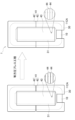
- FIG. 1 is a schematic diagram illustrating a first embodiment of the method for manufacturing a coil component according to the present invention.
- FIG. 2 is a schematic diagram for explaining a third embodiment of the method for manufacturing a coil component according to the present invention.
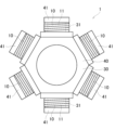
- FIG. 3 is a schematic diagram of a coil component manufactured by the fourth embodiment of the coil component manufacturing method of the present invention.
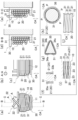
- FIG. 4 is a schematic diagram of one embodiment (fifth embodiment) of the coil component of the present invention.
- 5(a) and 5(b) are cross-sectional photographs of an example of the coil component of the present invention, and
- FIG. 5(c) is a cross-sectional photograph of a coil component of a comparative example.
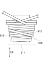
- FIG. 6 is a cross-point diagram of a coil formed by winding windings having a rectangular cross-sectional shape.
- a first embodiment which is an embodiment of a method for manufacturing a coil component according to the present invention, will be described with reference to FIG.
- a coil component 1 of this embodiment has at least one coil 10 and a core member 30 .
- the core member 30 includes at least one core portion 31 arranged inside at least one coil 10 respectively.
- the coil component 1 in FIG. 1 has one coil 10 and one core portion 31, they may be plural.
- the cross-sectional shape of the core portion 31 in FIG. 1 is rectangular, the cross-sectional shape of the core portion 31 is not particularly limited.
- the core portion 31 is made of a compressible material.
- the manufacturing method of the coil component 1 of this embodiment has a winding process and an isostatic pressing process.
- the winding 20 is wound around the core portion 31 in multiple layers to form at least one coil 10 .
- the number of layers of the coil 10 is four in FIG. 1, it may be more or less than four.
- the coil 10 has a cross point 11 at a portion in the circumferential direction where adjacent winding portions 21 in the stacking direction intersect when viewed in the stacking direction.
- the cross-sectional shape of the wire 20 in the winding process of FIG. 1 is circular, the cross-sectional shape of the wire 20 in the winding process of this embodiment may be rectangular.
- the isostatic pressing process is performed after the winding process.
- the isostatic pressing step at least the cross points 11 of the at least one coil 10 are pressed together with the core member 30 by isostatic pressing with the core portion 31 disposed inside the at least one coil 10 .
- the isostatic pressing performed in the isostatic pressing process is isostatic pressing using at least one of a liquid pressure medium, a gas pressure medium, and an elastic solid pressure medium.
- FIG. 1(a) shows an example of isostatic pressing using at least liquid pressure medium.
- the isostatic press in FIG. 1(a) is, for example, a wet cold isostatic press (WET CIP).
- WET CIP wet cold isostatic press
- the coil 10 and the core member 30 are enclosed in a flexible bag 53, and the bag 53 is placed in a liquid pressure medium 52 in a pressurized container 51, and the pressure medium 52 is pressurize.
- the portion of the coil 10 not pressed in the circumferential direction is covered with a cover. Air may remain in bag 53, although a vacuum is preferred. Bag 53 may or may not be made of rubber.
- FIG. 1(b) shows an example of isostatic pressing using at least a gaseous pressure medium.
- the isostatic pressing in FIG. 1(b) is, for example, hot isostatic pressing (HIP).
- the coil 10 and the core member 30 are enclosed in a flexible bag 63 , the bag 63 is placed in the pressurized container 61 , and the gas pressure medium 62 in the pressurized container 61 is pressurized.
- the bag 63 may preferably contain air, although a vacuum is preferred. Bag 63 may or may not be made of rubber.
- FIG. 1(c) shows an example of isostatic pressing using at least a liquid pressure medium and an elastic solid pressure medium.
- the isostatic press in FIG. 1(c) is, for example, a wet cold isostatic press (WET CIP).
- a rubber mold 73 in which the coil 10 and the core member 30 are arranged is enclosed in a flexible bag 74, and the bag 53 is placed in a liquid pressure medium 72 in a pressurized container 71 to pressurize the pressure medium 72. pressurize.
- the bag 73 may contain air.
- the rubber mold 73 corresponds to an elastic solid pressure medium. Instead of using the rubber mold 73 and the bag 74, a rubber bag may be used.
- FIG. 1(d) shows an example of isostatic pressing using a solid pressure medium having at least elasticity.
- the isostatic press in FIG. 1(d) is a rubber isostatic press (RIP).
- the coil 10 and the core member 30 are arranged in the rubber mold 82 arranged in the pressurized container 81 , and the rubber mold 82 is directly pressurized by the piston of the pressurized container 51 .
- the portion of the coil 10 not pressed in the circumferential direction is covered with a cover.
- the rubber mold 82 corresponds to an elastic solid pressure medium.
- FIGS. 1(e) and 1(f) show two examples of isostatic pressing situations with at least a liquid pressure medium and an elastic solid pressure medium.
- the isostatic press of FIGS. 1(e) and 1(f) is, for example, a dry cold isostatic press (DRY CIP).
- 1(e) and 1(f) is partitioned by a pressurized rubber mold 93 into a space in which a liquid pressure medium 92 is arranged and a space in which a molding rubber mold 94 is arranged. It is The coil 10 and the core member 30 are arranged in a molding rubber mold 94 and receive pressure from the pressure medium 92 via the molding rubber mold 94 and the pressure rubber mold 93 .
- the unpressed portion of the coil 10 in the circumferential direction is covered with a cover.
- the method of pressurizing the gas or liquid pressure medium in the pressurization containers 51, 61, 71, 91 is, for example, pushing the pressure medium pressurized by a pressurization device into the pressurization containers 51, 61, 71, 91.
- the pressure medium may be pressurized by the pistons of the pressurization containers 51, 61, 71, and 91.
- the cross-sectional area of the winding 20 is not locally reduced even though at least the cross points 11 of the coil 10 are pressed, and at least the cross points 11 are pressed. , the cross-sectional area of the winding 20 can be made larger than before pressing. Therefore, the electrical resistance of the coil 10 can be reduced.
- the following effects can be obtained. Since deformation of the winding 20 that locally reduces the cross-sectional area of the winding 20 does not occur, damage to the insulating coating of the winding 20 can be suppressed.
- the gaps between the winding portions 21 adjacent to each other in the coil axial direction CA may become large at the crosspoints 11 .
- the method of manufacturing the coil component 1 of the present embodiment it is possible to suppress the disturbance of the positions of the windings 20 at the cross points 11 . Therefore, the gap between the winding portions 21 at the cross point 11 and the gap between the winding portion 21 and the core portion 31 at the cross point 11 can be made smaller than when the cross point 11 is pressed with a mold. Therefore, the coil component 1 can be made smaller than when the cross points 11 are pressed with a die.
- the thermal conductivity of the coil component 1 can be improved as compared with the case where the cross points 11 are pressed with a mold.
- the leakage magnetic flux of the coil component 1 can be suppressed as compared with the case where the cross point 11 is pressed with a die.
- the core member 30 may have two flange portions 32 facing both ends of the cross point 11 in the coil axial direction CA in the coil axial direction CA.
- the cross point 11 cannot be pressed in the coil axial direction CA with a die. Therefore, in this case, although the gap between the winding portions 21 of adjacent layers at the cross point 11 and the gap between the winding portion 21 and the core portion 31 at the cross point 11 can be made smaller than before pressing, the cross point 11 cannot be made small.
- the core member 30 has two flange portions 32 facing each other in the coil axial direction CA and both ends of the cross point 11 in the coil axial direction CA.
- the gap between the winding portions 21 on adjacent layers at the crosspoint 11, the gap between the winding portion 21 and the core portion 31 at the crosspoint 11, and the winding portions 21 on the same layer at the crosspoint 11 can be made smaller than before pressing. Therefore, when the core member 30 has two flange portions 32, the difference in thermal conductivity of the coil component 1 between the manufacturing method of the coil component 1 of the present embodiment and the case where the cross points 11 are pressed with a mold is get bigger.
- the pressing force when pressing at least the cross points 11 of the coil 10 together with the core member 30 by isostatic pressing is not particularly limited.
- the pressure is preferably a pressure that can make the cross-sectional area of the winding 20 at least at the cross points 11 of the coil 10 larger than before pressing.
- the applied pressure may be, for example, 10 MPa or more, 20 MPa or more, or 30 MPa or more. If the conductor of the winding 20 is aluminum or an aluminum alloy, the applied pressure may be, for example, 10 MPa or more. If the conductor of the winding 20 is copper or a copper alloy, the applied pressure may be, for example, 20 MPa or more.
- the pressure may be such a pressure that the cross-sectional shape of the wire 20 is maintained circular.
- the method for manufacturing the coil component 1 of the present embodiment may include an insulating tape winding step of winding an insulating tape around the outer peripheral surface of the coil 10 after the winding step and before the isostatic pressing step. .
- the insulating tape may be impregnated with a thermosetting resin in advance. After winding the insulating tape, the insulating tape may be impregnated with a thermosetting resin. The insulating tape may not be impregnated with thermosetting resin. Both the insulating tape and the thermosetting resin have insulating properties.
- the thermosetting resin may be a resin that can be cured only at a temperature higher than room temperature, or a resin that can be cured even at room temperature.
- the adhesion between the insulating tape and the coil 10 is increased, so that the insulation of the coil 10 is improved. Further, in the isostatic pressing step, if the isostatic pressing is performed using a liquid or gas pressure medium having a temperature higher than normal temperature, curing of the thermosetting resin can be accelerated. Note that the method for manufacturing the coil component 1 of the present embodiment may not include such an insulating tape winding step.
- the inside of the core portion 31 is filled with, for example, rubber in the isostatic pressing process. Isostatic pressing may be performed in this state. As a result, the inner peripheral surface of the core portion 31 is isostatically pressed while suppressing deformation of the core portion 31 such that a portion of the inner peripheral surface of the core portion 31 protrudes or the inner diameter of the core portion 31 becomes smaller. can be done.
- the case where the portion of the core member 30 disposed inside the coil 10 is only the cylindrical core portion 31 means, for example, the case where the coil component 1 is used for a stator of a rotating electric machine and the core member 30 is an insulating bobbin. is.
- a second embodiment which is an embodiment of the method for manufacturing a coil component according to the present invention, will be described.
- the second embodiment has the following configuration in addition to the configuration of the first embodiment.
- the isostatic pressing step in the method for manufacturing the coil component 1 of the present embodiment the entire circumference of the coil 10 is pressed by isostatic pressing together with the core member 30 while the core portion 31 is arranged inside the coil 10. be.
- the pressurizing force when isostatically pressing the entire circumference of the coil 10 together with the core member 30 There is no particular limitation on the pressurizing force when isostatically pressing the entire circumference of the coil 10 together with the core member 30 .
- the cross-sectional shape of the winding 20 in the winding process is circular, increasing the pressure in the isostatic pressing process eventually results in six windings at a portion of the coil 10 in the circumferential direction that is not the cross point 11.
- the cross-sectional shape of the winding portion 21 surrounded by the wire portion 21 is deformed into a hexagon.
- the applied pressure may be smaller than the applied pressure that deforms the cross-sectional shape of the winding portion 21 surrounded by the six winding portions 21 into a hexagonal shape.
- the pressure may be such a pressure that the cross-sectional shape of the wire 20 is maintained circular.
- a third embodiment which is a method of manufacturing a coil component according to the present invention, will be described with reference to FIG.
- the third embodiment has the following configuration in addition to the configuration of the second embodiment.
- the core portion 31 of the present embodiment includes at least a portion of each of a plurality of components arranged side by side in a direction intersecting the coil axial direction CA and mechanically joined.
- the coil component 1 in FIG. 2 is a coil component 1 used in a stator of an outer rotor type or inner rotor type rotating electric machine, but the application of the coil component 1 of the present embodiment is not limited to this.
- the coil component 1 of the present embodiment may be the coil component 1 used in the stator of an axial gap type rotary electric machine or other electrical equipment.
- the core member 30 in FIG. 2 is composed of an insulating bobbin 41 and a stator core component 43 that is part of the stator core.
- Core portion 31 may be a portion of insulating bobbin 41 .
- core portion 31 may be composed of a portion of insulating bobbin 41 and a portion of stator core component 43 arranged inside insulating bobbin 41 .
- the stator core component 43 is composed of a plurality of electromagnetic steel plates 44 .
- the plurality of electromagnetic steel sheets 44 are arranged in a direction perpendicular to the coil axial direction CA.
- a plurality of electromagnetic steel plates 44 are mechanically joined by caulking.
- the insulating bobbin 41 is composed of two bobbin parts 42 .
- a stator core component 43 is arranged between two bobbin components 42 .
- the direction in which the two bobbin parts 42 are arranged is the same as the direction in which the plurality of electromagnetic steel plates 44 are arranged.
- the bobbin component 42 and the stator core component 43 may not be joined or may be mechanically joined by caulking or the like.
- the core portion 31 of FIG. 2 includes a plurality of parts 44, 44, . . . (or a plurality of parts 42, 42, 44, . 44, 44).
- the core portion 31 includes at least a portion of each of a plurality of components that are arranged side by side in a direction intersecting the coil axial direction CA and are mechanically joined together, the direction intersecting the coil axial direction CA is achieved by isostatic pressing.
- the length of the core portion 31 in can be shortened. Therefore, the lengths of the inner and outer circumferences of the coil 10 can be made shorter. As a result, the cross-sectional area of the winding 20 can be made larger, and the electrical resistance of the coil 10 can be further reduced.
- the coil component 1 can be further miniaturized.
- the gap between the winding portions 21 and the gap between the winding portion 21 and the core portion 31 can be made smaller. Therefore, the thermal conductivity of the coil component 1 can be further enhanced, and the leakage magnetic flux of the coil component 1 can be further suppressed.
- a fourth embodiment which is a method for manufacturing a coil component according to the present invention, will be described with reference to FIG.
- the fourth embodiment has the following configuration in addition to at least one configuration of the first to third embodiments.
- a coil component 1 of this embodiment has a core member 30 including a plurality of core portions 31 and a plurality of coils 10 .
- the plurality of coils 10 is formed by winding the plurality of windings 20 around the plurality of core portions 31 in multiple layers.
- Each coil 10 has cross points 11 in a portion of the circumferential direction.
- the cross points 11 of the plurality of coils 10 are arranged in a state in which the plurality of core portions 31 are arranged inside the plurality of coils 10. It is pressed together with the member 30 by an isostatic press.
- the core member 30 of this embodiment may be an annular member.
- a plurality of core portions 31 may be provided along the circumferential direction of the core member 30 .
- the coil component 1 of FIG. 3 is a coil component 1 used in a stator of an outer rotor type rotary electric machine, but the application of the coil component 1 of the present embodiment is not limited to this.
- the coil component 1 of the present embodiment may be a stator of an inner rotor type rotating electrical machine, a stator of an axial gap type rotating electrical machine, or a coil component 1 used in other electrical equipment.
- a core member 30 in FIG. 3 is composed of a stator core 40 and a plurality of insulating bobbins 41 .
- Core portion 31 may be a portion of insulating bobbin 41 .
- core portion 31 may be composed of a portion of insulating bobbin 41 and a portion of stator core 40 arranged inside insulating bobbin 41 .
- the structure of the core portion 31 may be the same as the structure of the core portion 31 in FIG.
- the stator core 40 may be of an integral type or a split type.
- Stator core 40 is an annular member.
- a plurality of insulating bobbins 41 are arranged on the outer peripheral portion of stator core 40 along the circumferential direction of stator core 40 .
- isostatic pressing may be performed in a state where the interior of the annular core member 30 is filled with, for example, rubber in the isostatic pressing step.
- the inner peripheral surface of the core member 30 is isostatically pressed while suppressing deformation of the core member 30 such that a part of the inner peripheral surface of the core member 30 protrudes or the inner diameter of the core member 30 becomes smaller. can be done.
- a fifth embodiment which is an embodiment of the coil component of the present invention, will be described with reference to FIG.
- a coil component 1 of the present embodiment has a coil 10 and a core member 30 including a core portion 31 arranged inside the coil 10 .
- the coil 10 is formed of windings 20 wound around a core portion 31 in multiple layers. 4(a), 4(c) to 4(e), the number of layers of the coil 10 is four, but may be more or less than four.
- An end portion of the winding 20 that is not wound around the core portion 31 is referred to as a lead portion 22 .
- the cross-sectional shape of the lead-out portion 22 is circular.
- the cross-sectional shape of the winding wire 20 is circular when the winding wire 20 is wound around the core portion 31 .
- the cross-sectional shape of the portion other than the ends of the windings 20 may be circular or may not be circular.
- the shape of the surface of the winding portion 21 forming the outer peripheral surface of the coil 10 is arcuate.
- the coil 10 has cross points 11 at a portion in the circumferential direction where adjacent winding portions 21 in the stacking direction intersect when viewed in the stacking direction.
- the coil 10 has parallel regions 12 in the other part in the circumferential direction, in which the upper winding portions 21 are arranged along the grooves formed by the lower winding portions 21 . have.
- the cross-sectional shape of the core portion 31 is not particularly limited.
- the core portion 31 is made of a compressible material.
- the core portion 31 is not molded integrally with the coil 10 . Therefore, the core portion 31 is not a core portion formed after the entire circumference of the coil 10 is pressed by isostatic pressing while nothing is arranged inside the coil 10 .
- the outer peripheral surface of the core portion 31 may have two parallel planes 33a and 33b.
- these two planes 33a and 33b are in contact with the winding 20.
- the core portion 31 is not a core portion arranged inside the coil 10 after the entire circumference of the coil 10 is pressed by the isostatic pressing while nothing is arranged inside the coil 10 .
- these two planes 33a and 33b may contact the winding 20 in one cross section orthogonal to the coil axial direction CA. 4(f) shows only the winding portion 21 of the lowest layer among the windings 20. As shown in FIG.
- the outer peripheral surface of the core portion 31 may have two non-parallel planes instead of two parallel planes.
- the planes 34a, 34b are not parallel
- the planes 34b, 34c are not parallel
- the planes 34c, 34a are not parallel.
- illustration is omitted, the outer peripheral surface of the core portion 31 may have two non-parallel planes and one curved surface instead of having two parallel planes.
- the core portion 31 is not a core portion arranged inside the coil 10 after the entire circumference of the coil 10 is pressed by the isostatic pressing while nothing is arranged inside the coil 10 .
- the plane or curved surface and the corner may contact the winding 20 (see, for example, FIG. 4(g)).
- FIG. 4G shows only the winding portion 21 of the lowest layer among the windings 20 .
- the cross-sectional shape of the core portion 31 may be circular or elliptical.
- the cross-sectional shape of the core portion 31 is circular or elliptical, three or more points P including both ends in the circumferential direction within the region 36 of 180° or more on the outer peripheral surface of the core portion 31 come into contact with the winding 20 . Therefore, the core portion 31 is not a core portion arranged inside the coil 10 after the entire circumference of the coil 10 is pressed by the isostatic pressing while nothing is arranged inside the coil 10 .
- FIG. 4(h) displays only the winding portion 21 of the lowest layer among the windings 20 .
- Plane 37 may be, for example, plane 33a or plane 33b of FIG. 4(f). Plane 37 may be, for example, any one of planes 34a to 34c in FIG. 4(g).
- a plurality of recesses 23 recessed in the stacking direction are formed in the circumferential direction in a portion of the outer peripheral surface of the coil 10 that covers the flat surface 37. They may exist side by side.
- the outermost winding portion 21a wound on the flat surface 37 may be bent to form the plurality of recesses 23.
- FIG. 4(i) in one cross section orthogonal to the coil axial direction CA, a plurality of recesses 23 recessed in the stacking direction are formed in the circumferential direction in a portion of the outer peripheral surface of the coil 10 that covers the flat surface 37. They may exist side by side.
- the outermost winding portion 21a wound on the flat surface 37 may be bent to form the plurality of recesses 23.
- the winding 20 is bent in the coil axial direction CA. Therefore, coil 10 is not an unpressed coil at all. Also, the coil 10 is not a coil in which only a part of the coil 10 in the circumferential direction except for the cross points 11 is pressed with a mold.
- a plurality of winding portions 21 arranged in the coil axial direction CA are It may bend in the coil axial direction CA while contacting the adjacent winding portions 21 .
- the plurality of winding portions 21 may be two winding portions 21 or three or more winding portions 21 .
- any cross section perpendicular to the circumferential direction of the coil component 1 and passing through the cross point 11 a plurality of winding portions located at ends in the coil axial direction CA
- a plurality of winding portions 21 excluding 21 do not include winding portions 21 having recesses that contact adjacent winding portions 21 at two opposing positions on the outer peripheral edge. Therefore, the coil 10 is not a coil with the crosspoints 11 pressed with a die.
- a point Q in FIG. 4E indicates a point where the winding portions 21 of adjacent layers are in point contact with each other at the cross point 11 .
- the cross-sectional shape of the winding portion 21 at 1 is apt to be deformed so as to have concave portions at two opposing locations on the outer peripheral edge.
- the cross-sectional area of the winding portion 21 deformed in this way is smaller than the cross-sectional area of the other winding portions 21 .
- the entire circumference of the coil 10 having the cross points 11 is pressed together with the core member 30 by an isostatic press while the core portion 31 is arranged inside the coil 10. It is the coil component 1 obtained by.
- the coil component 1 of the present embodiment may be manufactured, for example, by the method of manufacturing the coil component 1 of the second embodiment or the third embodiment. To prevent the cross-sectional area of a winding 20 from being locally reduced even though the entire circumference of a coil 10 having a cross point 11 is pressed, and to make the cross-sectional area of the winding 20 larger than before pressing. can be done. Therefore, the electric resistance of the coil 10 of the coil component 1 can be reduced. Moreover, since deformation of the winding 20 that locally reduces the cross-sectional area of the winding 20 does not occur, damage to the insulation coating of the winding 20 can be suppressed.
- the coil component 1 of this embodiment may further have the following features.
- a plurality of winding portions located at ends in the coil axial direction CA
- Each of the plurality of winding portions 21 excluding 21 is adjacent to the winding portion 21 in the coil axial direction CA and contacts the winding portion 21 not located at the end in the coil axial direction CA. Since the positional disturbance of the windings 20 is suppressed in this manner, the windings 20 are less likely to be deformed such that the cross-sectional area of the windings 20 is locally reduced at the cross points 11 during pressing.
- the gaps between the winding portions 21 at the cross points 11 and the A gap between the winding portion 21 and the core portion 31 can be reduced. Therefore, it is possible to reduce the size of the coil component 1, improve the thermal conductivity of the coil component 1, and suppress leakage magnetic flux of the coil component 1, as compared with the case where the cross points 11 are pressed with a die.
- the outer peripheral surface of the coil 10 of the coil component 1 of the present embodiment may be covered with an insulating tape, or with an insulating tape and a thermosetting resin, or may not be covered.
- FIGS. 5(a) and 5(b) are cross-sectional photographs of the cross points of the coil components of two Examples 1 and 2 of the present invention.
- FIG. 5(c) is a cross-sectional photograph of the cross point of the coil component of the comparative example.
- the entire periphery is pressed with a mold while the core portion is arranged inside the coil.
- the coil of Example 2 is isostatically pressed with a higher pressure than the coil of Example 1.
- the configurations of the coils before pressing in Example 1, Example 2, and Comparative Example are the same.
- the windings were hardened with resin so that the windings would not move, and then cut at the positions of the cross points. As shown in FIG.
- the cross-section of the crosspoint of the comparative example has a winding portion 901 having recesses 902 at two opposing positions on the outer peripheral edge.
- the two recesses 902 of the winding portion 901 contact adjacent winding portions.
- the winding portion 901 is a winding portion that is not positioned at an end in the coil axial direction CA.
- the maximum cross-sectional length of the winding portion 901 is longer than the maximum cross-sectional lengths of the other winding portions. This is because the position of the winding portion 901 is moved by pressing, and the inclination of the winding portion 901 in the wire length direction with respect to the circumferential direction of the coil is increased.
- the cross-sections of the crosspoints of Examples 1 and 2 do not have winding portions having recesses at two opposite positions on the outer periphery.
Landscapes
- Engineering & Computer Science (AREA)
- Power Engineering (AREA)
- Manufacturing & Machinery (AREA)
- Coils Or Transformers For Communication (AREA)
- Coil Winding Methods And Apparatuses (AREA)
- Coils Of Transformers For General Uses (AREA)
- Manufacture Of Motors, Generators (AREA)
- Manufacturing Cores, Coils, And Magnets (AREA)
Abstract
コイル部品(1)は、コイル(10)と、コイルの内部に配置されるコア部(31)を含むコア部材(30)とを有する。このコイル部品の製造方法は、巻回工程と、巻回工程の後の等方圧プレス工程とを有する。巻回工程において、巻線(20)がコア部(31)に多層に巻かれて、積層方向に隣り合う巻線部(21)が積層方向に見て交差するクロスポイント(11)を周方向の一部分に有するコイル(10)が形成される。等方圧プレス工程において、コイル(10)の内部にコア部(31)が配置された状態で、コイル(10)の少なくともクロスポイント(11)が、コア部材(30)と共に等方圧プレスによってプレスされる。
Description
本発明は、コイルと、コイルの内部に配置されるコア部を含むコア部材とを有するコイル部品の製造方法、および、コイル部品に関する。
従来、巻線が多層に巻かれて形成されたコイルが電機機器に使用されている。例えば、このコイルと、コイルの内部に配置されるコア部を含むコア部材とを有するコイル部品が、電機機器に含まれる。巻線を多層に巻く際、コイルの周方向の一部分において、上層の巻線部が積層方向に見て下層の巻線部と交差するように配置される。この部分をクロスポイントという。コイルのクロスポイントではない部分において、上層の巻線部は下層の巻線部の線長方向に沿って配置される。巻線の断面形状が円形の場合、コイルのクロスポイントではない部分において、上層の巻線部は下層の2つの巻線部によって形成される溝に沿って配置される。
特許文献1には、モータに使用されるコイル部品の製造方法が記載されている。特許文献1では、断面形状が円形の巻線がコア部(分割ステータコアの一部分とボビン)に多層に巻かれてコイルが形成された後、コイルの内部にコア部が配置された状態で、コイルのコイルエンドを除く部分が金型でプレスされている。コイルエンドとは、ステータのスロット内に配置されないコイルの周方向一部分である。モータ用コイルの場合、一般的に、コイルエンドがクロスポイントを含む。つまり、特許文献1では、クロスポイントは金型でプレスされていないと推定される。
断面形状が円形の巻線を巻いてコイルを形成した場合、コイルのクロスポイントではない部分において、上層の巻線部は下層の巻線部に線長方向に沿って線接触することができる。また、断面形状が矩形の巻線を巻いてコイルを形成した場合、コイルのクロスポイントではない部分において、上層の巻線部は下層の巻線部に線長方向に沿って面接触することができる。一方、断面形状が円形の巻線を巻いてコイルを形成した場合、クロスポイントにおいて、上層の巻線部は、交差する下層の巻線部に対して点接触でしか接触することができない。また、例えば図6に示すように、断面形状が矩形の巻線を巻いて層ごとのターン数が異なるコイル910を形成した場合、クロスポイント911において、ある層の複数の巻線部のうちコイル軸方向CAの端に位置する巻線部912が、下層の複数の巻線部のうちコイル軸方向CAの端に位置する巻線部913に対して線接触でしか接触しない場合がある。なお、図6中の破線が、線接触部を示す。このように、クロスポイントにおいて隣り合う層の巻線部同士が接触する面積は、クロスポイントではない部分において隣り合う層の巻線部同士が接触する面積よりも小さくなる。
コイルの外周面が金型でプレスされた場合、コイルの外周面は一方向の力だけを受ける。そのため、仮にクロスポイントが金型でプレスされると、クロスポイントにおいて巻線部同士が接触する面積の小さい箇所に力が集中的に作用する。その結果、力を集中的に受けた巻線部は、断面積が小さくなるように変形しやすい。このように局所的に巻線の断面積が小さくなると、コイルの電気抵抗が高くなる。つまり、仮に、コイルの少なくともクロスポイントを金型でプレスすると、コイルの電気抵抗が高くなりやすいと考えられる。しかし、コイルは電気抵抗が低いことが望ましい。
本発明は、コイルの少なくともクロスポイントをプレスしつつコイルの電気抵抗を低くすることが可能なコイル部品の製造方法およびコイル部品を提供することを目的とする。
本願の発明者らは、コイルの少なくともクロスポイントをプレスしつつコイルの電気抵抗を低減させるために、様々な試験を行った。その結果、コイルの内部にコア部が配置された状態で、コイルの少なくともクロスポイントをコア部材と共に等方圧プレスによってプレスした場合、局所的に巻線の断面積が小さくなることがなく、少なくともクロスポイントにおいて巻線の断面積をプレス前よりも大きくすることが可能であることに気付いた。それにより、コイルの電気抵抗を低減できる。本発明はこの知見に基づいている。なお、本明細書において、巻線(または巻線部)の断面積とは、巻線(または巻線部)の線長方向に直交する断面の面積を意味する。
本発明の一実施形態のコイル部品の製造方法は、以下の構成を有する。
コイルと前記コイルの内部に配置されるコア部を含むコア部材とを有するコイル部品の製造方法であって、巻線が前記コア部に多層に巻かれて、積層方向に隣り合う巻線部が前記積層方向に見て交差するクロスポイントを周方向の一部分に有する前記コイルが形成される巻回工程と、前記巻回工程の後、前記コイルの内部に前記コア部が配置された状態で、前記コイルの少なくとも前記クロスポイントが、前記コア部材と共に等方圧プレスによってプレスされる等方圧プレス工程とを有する。
コイルと前記コイルの内部に配置されるコア部を含むコア部材とを有するコイル部品の製造方法であって、巻線が前記コア部に多層に巻かれて、積層方向に隣り合う巻線部が前記積層方向に見て交差するクロスポイントを周方向の一部分に有する前記コイルが形成される巻回工程と、前記巻回工程の後、前記コイルの内部に前記コア部が配置された状態で、前記コイルの少なくとも前記クロスポイントが、前記コア部材と共に等方圧プレスによってプレスされる等方圧プレス工程とを有する。
この構成によると、コイルの少なくともクロスポイントが、コア部材と共に等方圧プレスによってプレスされる。ここで、等方圧プレス成形は、セラミックスの成形などに用いられ、等方的に圧力が作用するために、密度が均一で方向性の少ない成形体が得られる成形法である。コイルに対して等方圧プレスを掛けていくと、コイルおよびコア部材の内部の密度を均一に近づける方向に向かうため、内部空間(巻線部同士の隙間、巻線部とコア部材との隙間)が減少し、部材(巻線部またはコア部材)がお互いに近づく方向に巻線が動く。そのため、接触していない箇所が近くの部材(巻線部またはコア部材)に接触していく。そのため、クロスポイントにおいて巻線部同士が接触する面積の小さい箇所に力が集中的に作用することを抑制できる。したがって、クロスポイントが金型でプレスされたコイルとは異なり、クロスポイントにおいて局所的に巻線の断面積が小さくなることがない。
また、コイルの内部にコア部が配置された状態で、コイルの少なくともクロスポイントがコア部材と共に等方圧プレスによってプレスされるため、少なくともクロスポイントにおいて最下層の巻線部はコア部に向かう方向に移動し、少なくともクロスポイントにおいて最上層の巻線部もコア部に向かう方向に移動する。それにより、少なくともクロスポイントにおける巻線部は線長方向の圧縮力を受ける。そのため、少なくともクロスポイントにおいて巻線の断面積をプレス前よりも大きくすることができる。これに対して、仮に、コイルの内部に何も配置されていない状態でコイルの少なくともクロスポイントが等方圧プレスによってプレスされた場合、少なくともクロスポイントにおいて最上層の巻線部は下層に向かう方向に移動して巻線部の線長方向の圧縮力を受ける。しかし、コイル内部に部材が配置されていないと内部の密度が均一になる方向に動くため、少なくともクロスポイントにおいて最下層の巻線部は上層に向かう方向に移動して巻線部の線長方向の引張力を受ける。それにより、少なくともクロスポイントにおいて、少なくとも最下層の巻線部の断面積が小さくなる。そのため、コイルの内部にコア部が配置された状態で少なくともクロスポイントが等方圧プレスによってプレスされたコイルは、コイルの内部に何も配置されていない状態で少なくともクロスポイントが等方圧プレスによってプレスされたコイル比べて、少なくともクロスポイントにおいて巻線の断面積を大きくすることができる。
このように、コイルの少なくともクロスポイントがプレスされるにも関わらず局所的に巻線の断面積が小さくなることがなく、しかも、少なくともクロスポイントにおいて巻線の断面積をプレス前よりも大きくすることができる。そのため、コイルの電気抵抗を低減できる。
また、コイルの内部にコア部が配置された状態で、コイルの少なくともクロスポイントがコア部材と共に等方圧プレスによってプレスされるため、少なくともクロスポイントにおいて最下層の巻線部はコア部に向かう方向に移動し、少なくともクロスポイントにおいて最上層の巻線部もコア部に向かう方向に移動する。それにより、少なくともクロスポイントにおける巻線部は線長方向の圧縮力を受ける。そのため、少なくともクロスポイントにおいて巻線の断面積をプレス前よりも大きくすることができる。これに対して、仮に、コイルの内部に何も配置されていない状態でコイルの少なくともクロスポイントが等方圧プレスによってプレスされた場合、少なくともクロスポイントにおいて最上層の巻線部は下層に向かう方向に移動して巻線部の線長方向の圧縮力を受ける。しかし、コイル内部に部材が配置されていないと内部の密度が均一になる方向に動くため、少なくともクロスポイントにおいて最下層の巻線部は上層に向かう方向に移動して巻線部の線長方向の引張力を受ける。それにより、少なくともクロスポイントにおいて、少なくとも最下層の巻線部の断面積が小さくなる。そのため、コイルの内部にコア部が配置された状態で少なくともクロスポイントが等方圧プレスによってプレスされたコイルは、コイルの内部に何も配置されていない状態で少なくともクロスポイントが等方圧プレスによってプレスされたコイル比べて、少なくともクロスポイントにおいて巻線の断面積を大きくすることができる。
このように、コイルの少なくともクロスポイントがプレスされるにも関わらず局所的に巻線の断面積が小さくなることがなく、しかも、少なくともクロスポイントにおいて巻線の断面積をプレス前よりも大きくすることができる。そのため、コイルの電気抵抗を低減できる。
本発明の一実施形態のコイル部品の製造方法は、以下の構成を有してもよい。
前記コア部が、圧縮性材料で形成されている。
前記コア部が、圧縮性材料で形成されている。
仮にコア部が非圧縮性材料で形成されている場合、等方圧プレス工程において、コア部がコイル軸方向の力を受けることでコイル軸方向に直交する方向に膨らむように変形する。それにより、コイルの最下層の巻線部が上層に向かう方向に移動してしまう。これに対して、コア部が圧縮性材料で形成されているため、等方圧プレス工程において、コイルの最下層の巻線部は上層に向かう方向に移動しない。そのため、巻線の断面積をプレス前よりも大きくすることができ、コイルの電気抵抗を低減できる。
本発明の一実施形態のコイル部品の製造方法は、以下の構成を有してもよい。
前記等方圧プレス工程において、前記コイルの内部に前記コア部が配置された状態で、前記コイルの全周が前記コア部材と共に等方圧プレスによってプレスされる。
前記等方圧プレス工程において、前記コイルの内部に前記コア部が配置された状態で、前記コイルの全周が前記コア部材と共に等方圧プレスによってプレスされる。
この構成によると、コイルの内部にコア部が配置された状態で、クロスポイントを有するコイルの全周がコア部材と共に等方圧プレスによってプレスされる。そのため、コイルの内部にコア部が配置された状態で、コイルのクロスポイントを含む周方向一部分だけがコア部材と共に等方圧プレスによってプレスされた場合に比べて、巻線の断面積が大きくなる箇所を増やすことができる。また、巻線の断面積をより大きくすることができる場合がある。したがって、コイルの電気抵抗をより低減できる。
本発明の一実施形態のコイル部品の製造方法は、以下の構成を有してもよい。
前記コア部が、コイル軸方向に交差する方向に並んで配置され且つ機械的に接合された複数の部品の各々の少なくとも一部分を含む。
前記コア部が、コイル軸方向に交差する方向に並んで配置され且つ機械的に接合された複数の部品の各々の少なくとも一部分を含む。
この構成によると、等方圧プレス工程の直前において、コイル軸方向に交差する方向に並んで配置され且つ機械的に接合された複数の部品の間に、コイル軸方向に交差する方向の微小な隙間が生じている場合がある。この場合、等方圧プレス工程において、コイルの内部にコア部が配置された状態でコイルの全周がコア部材と共に等方圧プレスによってプレスされることによって、複数の部品の間のコイル軸方向に交差する方向の隙間を小さくできる。それにより、コイル軸方向に交差する方向におけるコア部の長さを短くできる。そのため、コイルの内周部および外周部の周長をより短くできる。その結果、巻線の断面積をより大きくすることができ、コイルの電気抵抗をより低減できる。
本発明の一実施形態のコイル部品の製造方法は、以下の構成を有してもよい。
前記コイル部品が、複数のコイルを有し、前記コア部材は、複数のコア部を有し、前記巻回工程において、複数の巻線が前記複数のコア部にそれぞれ多層に巻かれて、前記クロスポイントを各々の周方向の一部分に有する前記複数のコイルが形成され、前記等方圧プレス工程において、前記複数のコイルの内部に前記複数のコア部がそれぞれ配置された状態で、前記複数のコイルの少なくとも前記クロスポイントが、前記コア部材と共に等方圧プレスによってプレスされる。
前記コイル部品が、複数のコイルを有し、前記コア部材は、複数のコア部を有し、前記巻回工程において、複数の巻線が前記複数のコア部にそれぞれ多層に巻かれて、前記クロスポイントを各々の周方向の一部分に有する前記複数のコイルが形成され、前記等方圧プレス工程において、前記複数のコイルの内部に前記複数のコア部がそれぞれ配置された状態で、前記複数のコイルの少なくとも前記クロスポイントが、前記コア部材と共に等方圧プレスによってプレスされる。
この構成によると、複数のコイルの少なくともクロスポイントが同時にプレスされるにも関わらず局所的に巻線の断面積が小さくなることがなく、複数のコイルにおいて巻線の断面積をプレス前よりも大きくすることができる。そのため、複数のコイルの電気抵抗を低減できる。
本発明の一実施形態のコイル部品の製造方法は、以下の構成を有してもよい。
前記巻回工程において、断面形状が円形の巻線が巻かれて前記コイルが形成される。
前記巻回工程において、断面形状が円形の巻線が巻かれて前記コイルが形成される。
断面形状が円形の巻線を巻いてコイルを形成した場合、断面形状が矩形の巻線を巻いてコイルを形成した場合よりも、クロスポイントにおいて巻線部同士の隙間の容積が大きくなりやすい。そのため、コイルの内部にコア部が配置された状態で、コイルの少なくともクロスポイントがコア部材と共に等方圧プレスによってプレスされた場合、少なくともクロスポイントにおいてコイルの最上層の巻線部がコア部に向かう方向に移動する距離が、巻線の断面形状が矩形の場合よりも長くなりやすい。つまり、少なくともクロスポイントにおける巻線部は、巻線の断面形状が矩形の場合よりも大きい線長方向の圧縮力を受けることができる。そのため、少なくともクロスポイントにおける巻線の断面積を、巻回工程において断面形状が矩形の巻線を巻いてコイルを形成した場合よりも大きくすることができる。
本発明の一実施形態のコイル部品の製造方法は、以下の構成を有してもよい。
前記等方圧プレス工程で行われる前記等方圧プレスが、液体の圧力媒体、気体の圧力媒体、および弾性を有する固体の圧力媒体の少なくとも1つを用いた等方圧プレスである。
前記等方圧プレス工程で行われる前記等方圧プレスが、液体の圧力媒体、気体の圧力媒体、および弾性を有する固体の圧力媒体の少なくとも1つを用いた等方圧プレスである。
本発明の一実施形態のコイル部品は、以下の構成を有する。
コイルと前記コイルの内部に配置されるコア部を含むコア部材とを有するコイル部品である。前記コイルは、前記コア部に多層に巻かれた巻線で形成され、前記巻線の端部であって前記コア部に巻かれていない引き出し部の断面形状は円形であり、前記コイルは、周方向の一部分に、積層方向に隣り合う巻線部が前記積層方向に見て交差するクロスポイントを有し、前記周方向の他の一部分に、上層の巻線部が下層の巻線部によって形成される溝に沿って配置される並列領域を有する。前記コア部は、前記コイルと一体成形されていない。前記コア部の外周面が平行な2つの平面を有する場合、前記平行な2つの平面が前記巻線と接触し、前記コア部の外周面が平行な2つの平面を有さず平行でない2つの平面を有する場合、前記コア部の外周面の前記2つの平面の一方の平面とこの平面の端ではない角部が前記巻線と接触するか、または、前記コア部の外周面が有する曲面とこの曲面の端ではない角部が前記巻線と接触し、前記コア部の断面形状が円形または楕円形の場合、前記コア部の外周面の180°以上の領域内の前記周方向の両端を含む3点以上が前記巻線と接触する。前記コア部の外周面が1つの平面を有する場合、前記コイルの外周面のうち前記コア部の前記1つの平面を覆う部分において、前記積層方向に凹んだ複数の凹みが前記周方向に並んで存在するように前記巻線が曲がっており、前記コア部の断面形状が円形または楕円形の場合、前記クロスポイントではなく前記クロスポイントと前記並列領域との境界でもない前記コイルの一部分において、前記巻線がコイル軸方向に曲がっている。前記コイル部品の前記周方向に直交し前記クロスポイントを通るどの断面においても、前記コイル軸方向の端に位置する複数の巻線部を除く複数の巻線部が、隣り合う巻線部と接触する凹部を外周縁における対向する2つの位置に有する巻線部を含まない。
コイルと前記コイルの内部に配置されるコア部を含むコア部材とを有するコイル部品である。前記コイルは、前記コア部に多層に巻かれた巻線で形成され、前記巻線の端部であって前記コア部に巻かれていない引き出し部の断面形状は円形であり、前記コイルは、周方向の一部分に、積層方向に隣り合う巻線部が前記積層方向に見て交差するクロスポイントを有し、前記周方向の他の一部分に、上層の巻線部が下層の巻線部によって形成される溝に沿って配置される並列領域を有する。前記コア部は、前記コイルと一体成形されていない。前記コア部の外周面が平行な2つの平面を有する場合、前記平行な2つの平面が前記巻線と接触し、前記コア部の外周面が平行な2つの平面を有さず平行でない2つの平面を有する場合、前記コア部の外周面の前記2つの平面の一方の平面とこの平面の端ではない角部が前記巻線と接触するか、または、前記コア部の外周面が有する曲面とこの曲面の端ではない角部が前記巻線と接触し、前記コア部の断面形状が円形または楕円形の場合、前記コア部の外周面の180°以上の領域内の前記周方向の両端を含む3点以上が前記巻線と接触する。前記コア部の外周面が1つの平面を有する場合、前記コイルの外周面のうち前記コア部の前記1つの平面を覆う部分において、前記積層方向に凹んだ複数の凹みが前記周方向に並んで存在するように前記巻線が曲がっており、前記コア部の断面形状が円形または楕円形の場合、前記クロスポイントではなく前記クロスポイントと前記並列領域との境界でもない前記コイルの一部分において、前記巻線がコイル軸方向に曲がっている。前記コイル部品の前記周方向に直交し前記クロスポイントを通るどの断面においても、前記コイル軸方向の端に位置する複数の巻線部を除く複数の巻線部が、隣り合う巻線部と接触する凹部を外周縁における対向する2つの位置に有する巻線部を含まない。
この構成によると、巻線の端部であってコア部に巻かれていない引き出し部の断面形状は円形である。つまり、コア部に巻線を巻いた時点での巻線の断面形状は円形である。
また、この構成によると、コア部はコイルと一体成形されていない。したがって、コア部は、コイルの内部に何も配置されていない状態でコイルの全周が等方圧プレスによってプレスされた後に成形されたコア部ではない。
また、この構成によると、コア部の外周面が平行な2つの平面を有する場合、平行な2つの平面が巻線と接触する。コア部の外周面が平行な2つの平面を有さず平行でない2つの平面を有する場合、コア部の外周面の2つの平面のうちの一方の平面とこの平面の端ではない角部が巻線と接触するか、または、コア部の外周面が有する曲面とこの曲面の端ではない角部が巻線と接触する。コア部の断面形状が円形または楕円形の場合、コア部の外周面の180°以上の領域内の周方向の両端を含む3点以上が巻線と接触する。したがって、コア部は、コイルの内部に何も配置されていない状態でコイルの全周が等方圧プレスによってプレスされた後に、コイルの内部に配置されたコア部ではない。
また、この構成によると、コア部の外周面が1つの平面を有する場合、コイルの外周面のうちこの平面を覆う部分において、積層方向に凹んだ複数の凹みが周方向に並んで存在するように巻線が曲がっている。コア部の断面形状が円形または楕円形の場合、クロスポイントではなくクロスポイントと並列領域との境界でもないコイルの一部分において、巻線がコイル軸方向に曲がっている。したがって、コイルは、全くプレスされていないコイルではない。また、コイルは、クロスポイントを除くコイルの周方向一部分だけが金型でプレスされたコイルでもない。
また、この構成によると、コイル部品の周方向に直交しクロスポイントを通るどの断面においても、コイル軸方向の端に位置する複数の巻線部を除く複数の巻線部が、隣り合う巻線部と接触する凹部を外周縁における対向する2つの位置に有する巻線部を含まない。したがって、コイルは、クロスポイントが金型でプレスされたコイルではない。仮にクロスポイントが金型でプレスされた場合、クロスポイントにおいて巻線部の点接触する箇所に力が集中的に作用するため、クロスポイントにおいてコイルの軸方向の端ではない位置にある巻線部の断面形状が、外周縁の対向する2箇所に凹部を有するように変形しやすい。このように変形した巻線部の断面積は、他の巻線部の断面積よりも小さくなる。
したがって、上記の構成を有するコイル部品は、コイルの内部にコア部が配置された状態で、クロスポイントを有するコイルの全周がコア部材と共に等方圧プレスによってプレスされることで得られるコイル部品である。等方圧プレス成形は、セラミックスの成形などに用いられ、等方的に圧力が作用するために、密度が均一で方向性の少ない成形体が得られる成形法である。コイルに対して等方圧プレスを掛けていくと、コイルおよびコア部材の内部の密度を均一に近づける方向に向かうため、内部空間(巻線部同士の隙間、巻線部とコア部材との隙間)が減少し、部材(巻線部またはコア部材)がお互いに近づく方向に巻線が動く。そのため、接触していない箇所が近くの部材(巻線部またはコア部材)に接触していく。そのため、クロスポイントにおいて巻線部の点接触する箇所に力が集中的に作用することを抑制できる。したがって、クロスポイントが金型でプレスされたコイルとは異なり、クロスポイントにおいて局所的に巻線の断面積が小さくなることがない。
また、コイルの内部にコア部が配置された状態で、コイルの全周がコア部材と共に等方圧プレスによってプレスされるため、コイルの最下層の巻線部はコア部に向かう方向に移動し、コイルの最上層の巻線部もコア部に向かう方向に移動する。それにより、巻線は線長方向の圧縮力を受ける。そのため、巻線の断面積をプレス前よりも大きくすることができる。これに対して、仮に、コイルの内部に何も配置されていない状態でコイルの全周が等方圧プレスによってプレスされた場合、コイルの最上層の巻線部は下層に向かう方向に移動して巻線部の線長方向の圧縮力を受ける。しかし、コイル内部に部材が配置されていないと内部の密度が均一になる方向に動くため、コイルの最下層の巻線部は上層に向かう方向に移動して巻線部の線長方向の引張力を受ける。ぞれにより、少なくとも最下層の巻線部の断面積が小さくなる。そのため、コイルの内部にコア部が配置された状態で全周が等方圧プレスによってプレスされたコイルは、コイルの内部に何も配置されていない状態で全周が等方圧プレスによってプレスされたコイル比べて、巻線の断面積を大きくすることができる。
このように、クロスポイントを有するコイルの全周がプレスされるにも関わらず局所的に巻線の断面積が小さくなることがなく、しかも、巻線の断面積をプレス前よりも大きくすることができる。そのため、コイルの電気抵抗を低減できる。
また、この構成によると、コア部はコイルと一体成形されていない。したがって、コア部は、コイルの内部に何も配置されていない状態でコイルの全周が等方圧プレスによってプレスされた後に成形されたコア部ではない。
また、この構成によると、コア部の外周面が平行な2つの平面を有する場合、平行な2つの平面が巻線と接触する。コア部の外周面が平行な2つの平面を有さず平行でない2つの平面を有する場合、コア部の外周面の2つの平面のうちの一方の平面とこの平面の端ではない角部が巻線と接触するか、または、コア部の外周面が有する曲面とこの曲面の端ではない角部が巻線と接触する。コア部の断面形状が円形または楕円形の場合、コア部の外周面の180°以上の領域内の周方向の両端を含む3点以上が巻線と接触する。したがって、コア部は、コイルの内部に何も配置されていない状態でコイルの全周が等方圧プレスによってプレスされた後に、コイルの内部に配置されたコア部ではない。
また、この構成によると、コア部の外周面が1つの平面を有する場合、コイルの外周面のうちこの平面を覆う部分において、積層方向に凹んだ複数の凹みが周方向に並んで存在するように巻線が曲がっている。コア部の断面形状が円形または楕円形の場合、クロスポイントではなくクロスポイントと並列領域との境界でもないコイルの一部分において、巻線がコイル軸方向に曲がっている。したがって、コイルは、全くプレスされていないコイルではない。また、コイルは、クロスポイントを除くコイルの周方向一部分だけが金型でプレスされたコイルでもない。
また、この構成によると、コイル部品の周方向に直交しクロスポイントを通るどの断面においても、コイル軸方向の端に位置する複数の巻線部を除く複数の巻線部が、隣り合う巻線部と接触する凹部を外周縁における対向する2つの位置に有する巻線部を含まない。したがって、コイルは、クロスポイントが金型でプレスされたコイルではない。仮にクロスポイントが金型でプレスされた場合、クロスポイントにおいて巻線部の点接触する箇所に力が集中的に作用するため、クロスポイントにおいてコイルの軸方向の端ではない位置にある巻線部の断面形状が、外周縁の対向する2箇所に凹部を有するように変形しやすい。このように変形した巻線部の断面積は、他の巻線部の断面積よりも小さくなる。
したがって、上記の構成を有するコイル部品は、コイルの内部にコア部が配置された状態で、クロスポイントを有するコイルの全周がコア部材と共に等方圧プレスによってプレスされることで得られるコイル部品である。等方圧プレス成形は、セラミックスの成形などに用いられ、等方的に圧力が作用するために、密度が均一で方向性の少ない成形体が得られる成形法である。コイルに対して等方圧プレスを掛けていくと、コイルおよびコア部材の内部の密度を均一に近づける方向に向かうため、内部空間(巻線部同士の隙間、巻線部とコア部材との隙間)が減少し、部材(巻線部またはコア部材)がお互いに近づく方向に巻線が動く。そのため、接触していない箇所が近くの部材(巻線部またはコア部材)に接触していく。そのため、クロスポイントにおいて巻線部の点接触する箇所に力が集中的に作用することを抑制できる。したがって、クロスポイントが金型でプレスされたコイルとは異なり、クロスポイントにおいて局所的に巻線の断面積が小さくなることがない。
また、コイルの内部にコア部が配置された状態で、コイルの全周がコア部材と共に等方圧プレスによってプレスされるため、コイルの最下層の巻線部はコア部に向かう方向に移動し、コイルの最上層の巻線部もコア部に向かう方向に移動する。それにより、巻線は線長方向の圧縮力を受ける。そのため、巻線の断面積をプレス前よりも大きくすることができる。これに対して、仮に、コイルの内部に何も配置されていない状態でコイルの全周が等方圧プレスによってプレスされた場合、コイルの最上層の巻線部は下層に向かう方向に移動して巻線部の線長方向の圧縮力を受ける。しかし、コイル内部に部材が配置されていないと内部の密度が均一になる方向に動くため、コイルの最下層の巻線部は上層に向かう方向に移動して巻線部の線長方向の引張力を受ける。ぞれにより、少なくとも最下層の巻線部の断面積が小さくなる。そのため、コイルの内部にコア部が配置された状態で全周が等方圧プレスによってプレスされたコイルは、コイルの内部に何も配置されていない状態で全周が等方圧プレスによってプレスされたコイル比べて、巻線の断面積を大きくすることができる。
このように、クロスポイントを有するコイルの全周がプレスされるにも関わらず局所的に巻線の断面積が小さくなることがなく、しかも、巻線の断面積をプレス前よりも大きくすることができる。そのため、コイルの電気抵抗を低減できる。
本発明の一実施形態のコイル部品は、以下の構成を有してもよい。
前記コイル部品の前記周方向に直交し前記クロスポイントを通るどの断面においても、前記コイル軸方向の端に位置する複数の巻線部を除く複数の巻線部の各々は、前記コイル軸方向に隣り合い、前記コイル軸方向の端に位置しない巻線部と接触する。
前記コイル部品の前記周方向に直交し前記クロスポイントを通るどの断面においても、前記コイル軸方向の端に位置する複数の巻線部を除く複数の巻線部の各々は、前記コイル軸方向に隣り合い、前記コイル軸方向の端に位置しない巻線部と接触する。
クロスポイントでは隣り合う層の巻線部が交差しており、巻線の位置が乱れやすい。そのため、クロスポイントが金型でプレスされた場合、クロスポイントにおいて、コイル軸方向に隣り合う巻線部の間の隙間が大きくなる場合がある。これに対して、コイルの内部にコア部が配置された状態で全周が等方圧プレスによってプレスされた場合、クロスポイントを通るどの断面においても、コイル軸方向の端に位置する複数の巻線部を除く複数の巻線部の各々は、コイル軸方向に隣り合い、コイル軸方向の端に位置しない巻線部と接触することができる。このように巻線の位置の乱れが抑制されているため、プレス時に、クロスポイントにおいて局所的に巻線の断面積が小さくなるような巻線の変形が生じにくい。そのため、コイルの電気抵抗を低減できる。
なお、コイルの用途によっては、層ごとのターン数が異なるため、コイル軸方向の端に位置しない巻線部は、コイル軸方向に隣り合う巻線部と接触しない場合がある。
なお、コイルの用途によっては、層ごとのターン数が異なるため、コイル軸方向の端に位置しない巻線部は、コイル軸方向に隣り合う巻線部と接触しない場合がある。
本発明のコイル部品の製造方法および本発明のコイル部品において、コア部とは、コイルの内部に配置される部分である。コア部は、コイルの内部に配置されない部分を含まないコア部は、独立した部品でもよい。コア部の少なくとも一部は、コア部材の一部分と分離不能に一体化されていてもよい。
本発明のコイル部品の製造方法および本発明のコイル部品において、コイル部品の用途は、電気機器であれば特に限定されない。コイル部品は、コイルの電磁誘導を利用する電気機器に使用することができる。コイル部品は、例えば、回転電機の電機子、回転電機の界磁、インダクタ、変圧器(トランス)などに用いられてもよい。なお、回転電機は、モータおよび発電機の少なくとも一方として機能する電機機器である。コイル部品が回転電機の電機子に用いられる場合、コイル部品はローター(回転子)に利用されてもよくステータ(固定子)に用いられてもよい。コイル部品が回転電機のローターに用いられる場合、コイル部品のコア部材は、ローターコアを含んでもよく、ローターコアの一部だけを含んでもよく、ローターコアの少なくとも一部を含まなくてもよい。コイル部品が回転電機のステータに用いられる場合、コイル部品のコア部材は、ステータコアを含んでもよく、ステータコアの一部だけを含んでもよく、ステータコアの少なくとも一部を含まなくてもよい。コイル部品が回転電機の電機子に用いられる場合、コイル部品は、例えば、アキシャルギャップ型の回転電機のステータ、ラジアルギャップ型のインナーローター型の回転電機のステータ、または、ラジアルギャップ型のアウターローター型の回転電機のステータのステータに用いられてもよい。これ以降に説明において、回転電機のステータとは、回転電機の電機子であるステータを意味する。コイル部品がアキシャルギャップ型の回転電機のステータに用いられる場合、コア部材の断面形状は、例えば、矩形、二等辺三角形、等脚台形、または扇形である。本明細書において、コア部の断面形状とは、コイル軸方向に直交するコア部の断面の形状を意味する。コイル部品がラジアルギャップ型の回転電機のステータに用いられる場合、コア部の断面形状は、例えば矩形である。コイル部品が変圧器に用いられる場合、コア部材の断面形状は、例えば、矩形、円形、角丸長方形、またはオーバル(楕円形を含む)である。これ以降の説明において、単に回転電機と称する場合、アキシャルギャップ型またはラジアルギャップ型の回転電機を意味する。コイル部品が回転電機のステータに用いられる場合、回転電機のコイルの巻きの形式は集中巻きでもよく、分布巻きでもよい。
本発明のコイル部品の製造方法および本発明のコイル部品において、コイル部品は、複数のコア部を有するコア部材と複数のコイルとを有してもよく、単一のコア部を有するコア部材と単一のコイルとを有してもよい。コイル部品が回転電機のステータに用いられ、ステータが一体型または分割型ステータコアを有する場合、コア部材は、例えば、ステータコアと、複数の絶縁ボビンまたは複数の絶縁紙とを含んでもよい。この場合、コイル部品は、複数のコア部を有するコア部材と複数のコイルとを有する。絶縁ボビンまたは絶縁紙は、ステータコアとコイルとの間に配置される。コイル部品が回転電機のステータに用いられ、ステータが一体型または分割型ステータコアを有する場合、コア部材は、例えば、絶縁ボビンだけでもよい。この場合、コイル部品は、単一のコア部を有するコア部材と単一のコイルとを有する。コイル部品が回転電機のステータに用いられ、ステータが分割型ステータコアを有する場合、コア部材は、分割型ステータコアの一部分と単一の絶縁ボビンまたは単一の絶縁紙とを含んでもよい。この場合、コイル部品は、単一のコア部を有するコア部材と単一のコイルとを有する。コイル部品が回転電機のステータに用いられ、回転電機のコイルの巻きの形式が分布巻きの場合、コイル部品は、複数のコア部を有するコア部材と複数のコイルとを有する。この場合、1つのコア部は、回転電機の中心軸を中心とした周方向に離れた2つの部分で構成される。
本発明のコイル部品の製造方法および本発明のコイル部品において、コア部材は、コア部を含む第1部品と、第1部品と分離可能な第2部品を含んでいてもよい。本発明のコイル部品の製造方法は、第1部品のコア部に巻線を巻いてコイルを形成する巻回工程と、巻回工程の後、等方圧プレス工程の前に、第1部材を第2部材に連結してコア部材を形成する組み立て工程とを有してもよい。例えば、コイル部品が回転電機のステータに用いられる場合、第1部品が絶縁ボビンで、第2部品がステータコアでもよい。
本発明のコイル部品の製造方法および本発明のコイル部品において、コア部材は、コイルの周方向の少なくとも一部分のコイル軸方向の一端とコイル軸方向に向かい合う部分を有してもよい。本発明のコイル部品の製造方法および本発明のコイル部品において、コア部材は、コイルの周方向の少なくとも一部分のコイル軸方向の両端とそれぞれコイル軸方向に向かい合う2つの部分を有してもよい。本発明のコイル部品の製造方法および本発明のコイル部品において、コア部材は、コイルのコイル軸方向の一端と全周にわたってコイル軸方向に向かい合う部分を有してもよい。本発明のコイル部品の製造方法および本発明のコイル部品において、コア部材は、コイルのコイル軸方向の両端と全周にわたってコイル軸方向に向かい合う2つの部分を有してもよい。
本発明のコイル部品の製造方法において、コイルの少なくともクロスポイントを、コア部材と共に等方圧プレスによってプレスするとは、コイルの全周をコア部材と共に等方圧プレスによってプレスする場合と、コイルのクロスポイントを含む周方向一部分をコア部材と共に等方圧プレスによってプレスする場合を含む。コイルのクロスポイントを含む周方向一部分をコア部材と共に等方圧プレスによってプレスする場合、例えば、コイルのプレスしない周方向一部分をカバーで覆った状態で等方圧プレスによってプレスしてもよい。カバーは、例えば剛性の高い圧縮性材料で形成される。カバーは、例えばコア部材に固定される。カバーは、等方圧プレス工程中にコイルに押し付けられない。具体的には例えば、等方圧プレスはカバーが変形しないような加圧力で行われる。もしくは、カバーは、等方圧プレスの力を受けて多少変形してもコイルに接触しないように設けられる。また、どちらの場合も、カバーは、等方圧プレス工程中に、カバーとコイルとの間に、圧力媒体および/または後述する可撓性を有する袋が変形して入り込むことがないように設けられる。
本発明のコイル部品の製造方法において、液体の圧力媒体、気体の圧力媒体、および弾性を有する固体の圧力媒体の少なくとも1つを用いた等方圧プレスとは、コイルに等方的に圧力を付与する圧力媒体として、液体の圧力媒体、気体の圧力媒体、および弾性を有する固体の圧力媒体の少なくとも1つを用いることを意味する。液体の圧力媒体、気体の圧力媒体、および弾性を有する固体の圧力媒体の少なくとも1つを用いた等方圧プレスとは、液体の圧力媒体と気体の圧力媒体を用いた等方圧プレスでもよく、液体の圧力媒体と弾性を有する固体の圧力媒体を用いた等方圧プレスでもよく、気体の圧力媒体と弾性を有する固体の圧力媒体を用いた等方圧プレスでもよく、気体の圧力媒体と液体圧力媒体と弾性を有する固体の圧力媒体を用いた等方圧プレスでもよい。液体の圧力媒体とは、常温の液体の圧力媒体でもよく、常温より高温の液体の圧力媒体でもよい。気体の圧力媒体とは、常温の気体の圧力媒体でもよく、常温より高温の気体の圧力媒体でもよい。弾性を有する固体の圧力媒体は、ゴム弾性を有する固体の圧力媒体が好ましい。弾性を有する固体の圧力媒体は、ゴムでもよく、ゴム以外のエラストマーでもよい。液体の圧力媒体または気体の圧力媒体が用いられる場合、等方圧プレス工程において、コイルとコア部材は、可撓性を有する袋に封入される。可撓性を有する袋は、弾性を有する固体の圧力媒体であってもなくてもよい。例えば、可撓性を有する袋の厚みがごく薄い場合は、可撓性を有する袋は弾性を有する固体の圧力媒体ではない。可撓性を有する袋の中は真空が好ましいが空気が残っていてもよい。コイルの外周面は、液体の圧力媒体に接触しない。コイルの外周面は、気体の圧力媒体に接触しない。コイルの外周面は、弾性を有する固体の圧力媒体または可撓性を有する袋に接触する。圧力媒体として少なくとも液体の圧力媒体を用いた等方圧プレスとは、例えば、湿式冷間等方圧プレス(WET CIP:Wet type Cold Isostatic PressingまたはWet-Bag Cold Isostatic Pressing)、乾式冷間等方圧プレス(DRY CIP:Dry type Cold Isostatic Pressing またはDry-Bag Cold Isostatic Pressing)、または、常温よりも高温の液体の圧力媒体を用いた等方圧プレスが該当する。圧力媒体として少なくとも気体の圧力媒体を用いた等方圧プレスとは、例えば、熱間等方圧プレス(HIP:Hot Isostatic Pressing)、または、常温の気体の圧力媒体を用いる等方圧プレスが該当する。圧力媒体として少なくとも弾性を有する固体の圧力媒体を用いた等方圧プレスとは、例えば、乾式冷間等方圧プレス(DRY CIP:Dry type Cold Isostatic Pressing またはDry-Bag Cold Isostatic Pressing)、または、ゴム等方圧プレス(RIP:Rubber Isostatic Pressing)が該当する。湿式冷間等方圧プレス(WET CIP)および乾式冷間等方圧プレス(DRY CIP)では、常温の液体の圧力媒体が用いられる。熱間等方圧プレス(HIP)では、高温の気体の圧力媒体が用いられる。熱間等方圧プレスは、プレスと加熱処理を同時に行えるプレス加工法である。熱間等方圧プレスにおける気体の圧力媒体の温度は、常温よりも高温であれば特に限定されない。
本発明のコイル部品の製造方法および本発明のコイル部品において、巻線は、導体と、導体の外周面を覆う絶縁皮膜とを有する。巻線は、単線でもよく撚線でもよい。本発明のコイル部品の製造方法および本発明のコイル部品において、巻線部とは、巻線の一部分を意味する。本発明のコイル部品の製造方法および本発明のコイル部品において、積層方向とは、巻線によって形成された複数の層が積層される方向である。本明細書において上層と下層は、複数の層のうち積層方向に隣り合ういずれか2つの層を指す。下層は上層よりもコア部に近い層である。本発明のコイル部品の製造方法および本発明のコイル部品において、クロスポイントは、積層方向に隣り合う2つの巻線部が積層方向に見て交差する箇所だけを意味する用語ではない。クロスポイントは、少なくとも、ある層の複数の巻線部と積層方向に見て交差する隣りの層の1つの巻線部を含む。クロスポイントにおいて、各層の少なくとも1つの巻線部が、隣りの層の巻線部と積層方向に見て交差していてもよい。本発明のコイル部品の製造方法および本発明のコイル部品におけるコイルは、周方向一部分にクロスポイントを有する。コイルのクロスポイントではない周方向一部分において、上層の巻線部は下層の巻線部の線長方向に沿って配置される。本発明のコイル部品の製造方法および本発明のコイル部品において、コイルは、2つのクロスポイントを有してもよく、単一のクロスポイントを有してもよい。本発明のコイル部品において、並列領域は、少なくとも、ある層の2つの巻線部によって形成される溝に沿って配置される、それより上層の1つの巻線部を含む。並列領域において、最下層以外の各層の少なくとも1つの巻線部が、隣りの層の2つの巻線部によって形成される溝に沿って配置されてもよい。本発明のコイル部品において、コイルの巻き方式は、直交巻き(Orthocyclic winding)である。本発明のコイル部品のコイルの製造方法において、コイルの巻き方式は、直交巻き(Orthocyclic winding)でもよい。本発明のコイル部品の製造方法において、コイルの巻き方式は、乱巻き(Wild winding)でもなく、螺旋巻き(Helical winding)でもない。
本発明のコイル部品の製造方法において、圧縮性材料で形成されたコア部とは、0.49よりも小さいポアソン比の圧縮性材料で形成されたコア部を意味する。本発明のコイル部品において、コア部は、0.49よりも小さいポアソン比の圧縮性材料で形成されてもよい。
本発明のコイル部品の製造方法において、機械的に接合された複数の部品とは、例えば、ねじやボルトなどの締結部材を用いて接合された複数の部品であってもよく、かしめによって接合された複数の部品であってもよい。かしめによって接合された複数の部品は、例えば、複数の電磁鋼鈑でもよい。本発明のコイル部品の製造方法において、コア部が、コイル軸方向に交差する方向に並んで配置され且つ機械的に接合された複数の部品を含む場合、この複数の部品は、コイル軸方向に直交する方向に並んでいてもよい。
本発明のコイル部品の製造方法において、断面形状が円形の巻線とは、巻線の線長方向に直交する断面の形状が円形である巻線を意味する。本明細書において、巻線の断面形状とは、巻線の線長方向に直交する断面の形状を意味する。本明細書において、巻線部の断面形状とは、巻線部の線長方向に直交する断面の形状を意味する。
本発明のコイル部品において、断面形状が円形の引き出し部とは、引き出し部の線長方向に直交する断面の形状が円形である引き出し部を意味する。本発明のコイル部品において、巻線の端部である引き出し部は、巻線の引き出し部を除く部分に溶接等で接続されたものではなく、巻線の引き出し部を除く部分と同じ構造を有する。
本発明のコイル部品において、断面形状が円形の引き出し部とは、引き出し部の線長方向に直交する断面の形状が円形である引き出し部を意味する。本発明のコイル部品において、巻線の端部である引き出し部は、巻線の引き出し部を除く部分に溶接等で接続されたものではなく、巻線の引き出し部を除く部分と同じ構造を有する。
本発明のコイル部品において、コイルと一体成形されていないコア部は、空芯のコイルが配置された型に磁性材料を充填して加圧成形されたコア部ではないコア部を意味する。コア部がコイルと一体成形されているかどうかは、コア部の外周面の形状を観察することで判断できる。コア部がコイルと一体成形される場合、例えば磁性体粉末と樹脂を混合した成形材料が、最下層の巻線部同士の隙間に入り込んだ状態で固化する。そのため、コア部がコイルと一体成形されている場合、コア部の外周面に、隣り合う巻線部同士の隙間に配置される突起が形成されている。
本発明のコイル部品において、コア部の外周面が平行な2つの平面を有する場合とは、例えば、コア部のコイル軸方向に直交する断面の形状が、矩形、角丸長方形、台形などの場合である。本発明のコイル部品において、コア部の外周面が平行な2つの平面を有さず平行でない2つの平面を有する場合とは、例えば、コア部のコイル軸方向に直交する断面の形状が、三角形または扇形などの場合である。本発明のコイル部品において、断面形状が円形または楕円形のコア部とは、コイル軸方向に直交するコア部の断面の形状が円形または楕円形のコア部を意味する。
本発明のコイル部品において、コア部の外周面が平行な2つの平面を有さず平行でない2つの平面を有する場合、コア部の外周面は曲面を有してもよく有さなくてもよい。コア部の外周面が平行な2つの平面を有さず平行でない2つの平面と1つの曲面を有する場合、平行でない2つの平面のうちの一方の平面とこの平面の端ではない角部が巻線と接触してもよく、この曲面とこの曲面の端ではない角部が巻線と接触してもよい。
本発明のコイル部品において、コア部の外周面の180°以上の領域内の周方向の両端を含む3点以上が巻線と接触する場合とは、この3つ以上の点がコア部の外周面における180°より小さい領域内に収まる場合を含まない。本発明のコイル部品において、コア部の外周面における3点以上が巻線と接触するとは、コア部の外周面における周方向に離れた3つ以上の箇所が、巻線と接触することを意味する。接触は、点接触でも線接触でも面接触でもよい。
本発明のコイル部品は、コア部の外周面が1つの平面を有する場合、コイルの外周面のうちこの1つの平面を覆う部分において、積層方向に凹んだ複数の凹みが前記周方向に並んで存在するように巻線が曲がっているという特徴を有する。この場合、コイルの外周面のうちコア部の1つの平面を覆う部分において、巻線が積層方向に曲がっている。コイルの外周面の一部分において巻線が積層方向に曲がっているとは、コイルの外周面の一部分を構成するいずれかの巻線部が積層方向に曲がっていることを意味する。また、この特徴において、コイルの外周面のうちコア部の1つの平面を覆う部分とは、積層方向に見て、コイルの外周面のうちコア部の1つの平面と重なる部分を意味する。
本発明のコイル部品において、クロスポイントではなくクロスポイントと並列領域との境界でもないコイルの一部分とは、並列領域でもよく、並列領域ではない領域でもよい。ここでの並列領域ではない領域は、例えば、巻線を巻いてコイルを形成した時点では並列領域であって、等方圧プレスの後に並列領域ではなくなった領域である。
本発明のコイル部品は、コイル部品の前記周方向に直交しクロスポイントを通るどの断面においても、コイル軸方向の端に位置する複数の巻線部を除く複数の巻線部が、隣り合う巻線部と接触する凹部を外周縁における対向する2つの位置に有する巻線部を含まないという特徴を有する。この特徴において、コイル軸方向の端に位置する複数の巻線部を除く複数の巻線部とは、コイル軸方向の一端に位置する複数の巻線部とコイル軸方向の他端に位置する複数の巻線部との間に位置する複数の巻線部を意味する。また、この特徴において、凹部を外周縁における対向する2つの位置に有する巻線部とは、例えば、巻線部の断面のほぼ中心を通る直線と巻線部の外周縁との2つの交点に凹部を有する巻線部でもよい。また、凹部を外周縁における対向する2つの位置に有する巻線部とは、例えば、巻線部の断面を、2つの凹部の一方である第1凹部を含む第1の領域と、第1の領域と同じ面積の第2の領域に分割した場合に、2つの凹部の他方である第2凹部が必ず第2の領域に存在し、第2凹部が第1の領域に存在するように分割できないような、2つの凹部を有する巻線部でもよい。
請求の範囲において、ある構成要素の数を明確に特定しておらず、英語に翻訳された場合にこの構成要素が単数で表示される場合、本発明はこの構成要素を複数有してもよい。また、本発明はこの構成要素を1つだけ有してもよい。
なお、本発明および実施の形態において、含む(including)、有する(comprising)、備える(having)およびこれらの派生語は、列挙されたアイテム及びその等価物に加えて追加的アイテムをも包含することが意図されて用いられている。
他に定義されない限り、本明細書および請求の範囲で使用される全ての用語(技術用語および科学用語を含む)は、本発明が属する当業者によって一般的に理解されるのと同じ意味を有する。一般的に使用される辞書に定義された用語のような用語は、関連する技術および本開示の文脈における意味と一致する意味を有すると解釈されるべきであり、理想化されたまたは過度に形式的な意味で解釈されることはない。
本明細書において、「しても良い」という用語は非排他的なものである。「しても良い」は、「しても良いがこれに限定されるものではない」という意味である。本明細書において、「してもよい」は、「しない」場合があることを暗黙的に含む。
本発明の実施形態を詳細に説明する前に、本発明は、以下の説明に記載されたまたは図面に図示された構成要素の構成および配置の詳細に制限されないことが理解されるべきである。本発明は、後述する実施形態以外の実施形態でも可能である。本発明は、後述する実施形態に様々な変更を加えた実施形態でも可能である。
本発明のコイル部品の製造方法および本発明のコイル部品によると、コイルの少なくともクロスポイントをプレスしつつコイルの電気抵抗を低くすることができる。
<第1実施形態>
本発明のコイル部品の製造方法の実施形態である第1実施形態について、図1を参照しつつ説明する。本実施形態のコイル部品1は、少なくとも1つのコイル10と、コア部材30とを有する。コア部材30は、少なくとも1つのコイル10の内部にそれぞれ配置される少なくとも1つのコア部31を含む。図1におけるコイル部品1が有するコイル10とコア部31の数はそれぞれ1つであるが、複数でもよい。図1におけるコア部31の断面形状は矩形であるが、コア部31の断面形状は特に限定されない。コア部31は、圧縮性材料で形成されている。
本発明のコイル部品の製造方法の実施形態である第1実施形態について、図1を参照しつつ説明する。本実施形態のコイル部品1は、少なくとも1つのコイル10と、コア部材30とを有する。コア部材30は、少なくとも1つのコイル10の内部にそれぞれ配置される少なくとも1つのコア部31を含む。図1におけるコイル部品1が有するコイル10とコア部31の数はそれぞれ1つであるが、複数でもよい。図1におけるコア部31の断面形状は矩形であるが、コア部31の断面形状は特に限定されない。コア部31は、圧縮性材料で形成されている。
本実施形態のコイル部品1の製造方法は、巻回工程と等方圧プレス工程とを有する。巻回工程では、巻線20がコア部31に多層に巻かれて少なくとも1つのコイル10が形成される。図1では、コイル10の層数は4つであるが4つよりも多くても少なくてもよい。コイル10は、周方向の一部分に、積層方向に隣り合う巻線部21が積層方向に見て交差するクロスポイント11を有する。図1の巻回工程における巻線20の断面形状は円形であるが、本実施形態の巻回工程における巻線20の断面形状は矩形でもよい。
等方圧プレス工程は、巻回工程の後に行われる。等方圧プレス工程では、少なくとも1つのコイル10の内部にコア部31が配置された状態で、少なくとも1つのコイル10の少なくともクロスポイント11が、コア部材30と共に等方圧プレスによってプレスされる。
等方圧プレス工程で行われる等方圧プレスは、液体の圧力媒体、気体の圧力媒体、および弾性を有する固体の圧力媒体の少なくとも1つを用いた等方圧プレスである。
図1(a)は、少なくとも液体の圧力媒体を用いた等方圧プレスを行っている状況の一例を示す。図1(a)の等方圧プレスは、例えば、湿式冷間等方圧プレス(WET CIP)である。図1(a)では、コイル10とコア部材30を、可撓性を有する袋53に封入し、この袋53を加圧容器51内の液体の圧力媒体52の中に入れて、圧力媒体52を加圧する。但し、コイル10の周方向の一部分のみをプレスする場合は、コイル10のプレスしない周方向一部分をカバーで覆っておく。袋53の中は真空が好ましいが空気が残っていてもよい。袋53はゴム製であってもなくてもよい。
図1(b)は、少なくとも気体の圧力媒体を用いた等方圧プレスを行っている状況の一例を示す。図1(b)の等方圧プレスは、例えば、熱間等方圧プレス(HIP)である。コイル10とコア部材30を、可撓性を有する袋63に封入し、この袋63を加圧容器61内に配置し、加圧容器61内の気体の圧力媒体62を加圧する。但し、コイル10の周方向の一部分のみをプレスする場合は、コイル10のプレスしない周方向一部分をカバーで覆っておく。袋63の中は真空が好ましいが空気が残っていてもよい。袋63はゴム製であってもなくてもよい。
図1(c)は、少なくとも液体の圧力媒体と弾性を有する固体の圧力媒体を用いた等方圧プレスを行っている状況の一例を示す。図1(c)の等方圧プレスは、例えば、湿式冷間等方圧プレス(WET CIP)である。コイル10とコア部材30が配置されたゴム型73を、可撓性を有する袋74に封入し、この袋53を加圧容器71内の液体の圧力媒体72の中に入れて、圧力媒体72を加圧する。但し、コイル10の周方向の一部分のみをプレスする場合は、コイル10のプレスしない周方向一部分をカバーで覆っておく。袋73の中は真空が好ましいが空気が残っていてもよい。ゴム型73は弾性を有する固体の圧力媒体に該当する。なお、ゴム型73および袋74を用いる代わりに、ゴム製の袋を用いてもよい。
図1(d)は、少なくとも弾性を有する固体の圧力媒体を用いた等方圧プレスを行っている状況の一例を示す。図1(d)の等方圧プレスは、ゴム等方圧プレス(RIP)である。加圧容器81内に配置されたゴム型82にコイル10とコア部材30を配置し、加圧容器51が有するピストンによってゴム型82を直接加圧する。但し、コイル10の周方向の一部分のみをプレスする場合は、コイル10のプレスしない周方向一部分をカバーで覆っておく。ゴム型82は弾性を有する固体の圧力媒体に該当する。
図1(e)および図1(f)は、少なくとも液体の圧力媒体と弾性を有する固体の圧力媒体を用いた等方圧プレスを行っている状況の2つの例を示す。図1(e)および図1(f)の等方圧プレスは、例えば、乾式冷間等方圧プレス(DRY CIP)である。図1(e)および図1(f)の加圧容器91の内部空間は、加圧ゴム型93によって、液体の圧力媒体92が配置される空間と成形ゴム型94が配置される空間に仕切られている。コイル10とコア部材30は成形ゴム型94に配置され、成形ゴム型94と加圧ゴム型93を介して圧力媒体92の圧力を受ける。コイル10の周方向の一部分のみをプレスする場合は、コイル10のプレスしない周方向一部分をカバーで覆っておく。
なお、加圧容器51、61、71、91内の気体または液体の圧力媒体を加圧する方法は、例えば、昇圧装置によって加圧された圧力媒体を加圧容器51、61、71、91に押し込むという方法でもよく、加圧容器51、61、71、91が有するピストンによって圧力媒体を加圧するという方法でもよい。
なお、加圧容器51、61、71、91内の気体または液体の圧力媒体を加圧する方法は、例えば、昇圧装置によって加圧された圧力媒体を加圧容器51、61、71、91に押し込むという方法でもよく、加圧容器51、61、71、91が有するピストンによって圧力媒体を加圧するという方法でもよい。
本実施形態のコイル部品1の製造方法によると、コイル10の少なくともクロスポイント11がプレスされるにも関わらず局所的に巻線20の断面積が小さくなることがなく、しかも、少なくともクロスポイント11において巻線20の断面積をプレス前よりも大きくすることができる。そのため、コイル10の電気抵抗を低減できる。
本実施形態のコイル部品1の製造方法によると、さらに以下の効果を得ることができる。局所的に巻線20の断面積が小さくなるような巻線20の変形が生じないため、巻線20の絶縁皮膜が破損することを抑制できる。
クロスポイント11が金型でプレスされた場合、クロスポイント11において、コイル軸方向CAに隣り合う巻線部21の間の隙間が大きくなる場合がある。これに対して、本実施形態のコイル部品1の製造方法によると、クロスポイント11における巻線20の位置の乱れを抑制できる。そのため、クロスポイント11を金型でプレスした場合に比べて、クロスポイント11における巻線部21同士の隙間と、クロスポイント11における巻線部21とコア部31との隙間を小さくできる。そのため、クロスポイント11を金型でプレスした場合に比べて、コイル部品1を小型化することができる。また、クロスポイント11を金型でプレスした場合に比べて、コイル部品1の熱伝導性を高めることができる。また、クロスポイント11を金型でプレスした場合に比べて、コイル部品1の漏れ磁束を抑制できる。
例えば図1に示すように、コア部材30は、クロスポイント11のコイル軸方向CAの両端とコイル軸方向CAに向かい合う2つのつば部32を有していてもよい。コイル10の内部にコア部31が配置され、且つ、2つのつば部32の間にクロスポイント11が配置された状態で、クロスポイント11をコイル軸方向CAに金型でプレスすることはできない。そのため、この場合には、クロスポイント11における隣り合う層の巻線部21同士の隙間と、クロスポイント11における巻線部21とコア部31との隙間はプレス前よりも小さくできるものの、クロスポイント11における同じ層の巻線部21同士の隙間は小さくできない。一方、本実施形態のコイル部品1の製造方法の等方圧プレス工程によると、コア部材30が、クロスポイント11のコイル軸方向CAの両端とコイル軸方向CAに向かい合う2つのつば部32を有していても、クロスポイント11における隣り合う層の巻線部21同士の隙間と、クロスポイント11における巻線部21とコア部31との隙間と、クロスポイント11における同じ層の巻線部21同士の隙間を、プレス前よりも小さくすることができる。そのため、コア部材30が2つのつば部32を有する場合には、本実施形態のコイル部品1の製造方法とクロスポイント11を金型でプレスする場合とのコイル部品1の熱伝導性の差がより大きくなる。
なお、本実施形態において、コイル10の少なくともクロスポイント11をコア部材30と共に等方圧プレスによってプレスするときの加圧力は、特に限定されない。加圧力は、コイル10の少なくともクロスポイント11の巻線20の断面積をプレス前よりも大きくすることができる加圧力が好ましい。加圧力は例えば10MPa以上でもよく、20MPa以上でもよく、30MPa以上でもよい。巻線20の導体がアルミニウムまたはアルミニウム合金の場合、加圧力は例えば10MPa以上でもよい。巻線20の導体が銅または銅合金の場合、加圧力は例えば20MPa以上でもよい。巻回工程における巻線20の断面形状が円形の場合、加圧力は、巻線20の断面形状が円形で維持される程度の加圧力でもよい。
なお、本実施形態のコイル部品1の製造方法は、巻回工程の後、等方圧プレス工程の前に、絶縁テープをコイル10の外周面に巻く絶縁テープ巻回工程を有してもよい。絶縁テープには予め熱硬化性樹脂が含侵されていてもよい。絶縁テープを巻回した後に、熱硬化性樹脂を絶縁テープに含侵させてもよい。絶縁テープには熱硬化性樹脂が含侵されなくてもよい。絶縁テープおよび熱硬化性樹脂はどちらも絶縁性を有する。熱硬化性樹脂は、常温より高い温度でのみ硬化が可能な樹脂でもよく、常温でも硬化可能な樹脂でもよい。コイル10の少なくともクロスポイント11が等方圧プレスによってプレスされることで、絶縁テープとコイル10との密着性が高まるため、コイル10の絶縁性が向上する。また、等方圧プレス工程において、常温より高温の液体または気体の圧力媒体を用いた等方圧プレスを行った場合は、熱硬化性樹脂の硬化を早めることができる。なお、本実施形態のコイル部品1の製造方法は、このような絶縁テープ巻回工程を有さなくてもよい。
なお、本実施形態において、コア部材30におけるコイル10の内部に配置される部分が、筒状のコア部31のみの場合、等方圧プレス工程において、コア部31の内部を例えばゴムなどで埋めた状態で等方圧プレスを行ってもよい。これにより、コア部31の内周面の一部分が突出したりコア部31の内径が小さくなるようなコア部31の変形を抑制しつつ、コア部31の内周面に等方圧プレスをかけることができる。なお、コア部材30におけるコイル10の内部に配置される部分が筒状のコア部31のみの場合とは、例えば、コイル部品1が回転電機のステータに用いられ、コア部材30が絶縁ボビンの場合である。
<第2実施形態>
本発明のコイル部品の製造方法の実施形態である第2実施形態について説明する。第2実施形態は、第1実施形態の構成に加えて以下の構成を有する。本実施形態のコイル部品1の製造方法における等方圧プレス工程では、コイル10の内部にコア部31が配置された状態で、コイル10の全周がコア部材30と共に等方圧プレスによってプレスされる。コイル10の全周をコア部材30と共に等方圧プレスによってプレスするときの加圧力は、特に限定されない。巻回工程における巻線20の断面形状が円形の場合、等方圧プレス工程の加圧力を高くしていくと、最終的に、コイル10のクロスポイント11ではない周方向一部分において、6つの巻線部21によって囲まれた巻線部21の断面形状は六角形に変形する。加圧力は、6つの巻線部21によって囲まれた巻線部21の断面形状が六角形に変形する加圧力よりも小さくてよい。巻回工程における巻線20の断面形状が円形の場合、加圧力は、巻線20の断面形状が円形で維持される程度の加圧力でもよい。
本発明のコイル部品の製造方法の実施形態である第2実施形態について説明する。第2実施形態は、第1実施形態の構成に加えて以下の構成を有する。本実施形態のコイル部品1の製造方法における等方圧プレス工程では、コイル10の内部にコア部31が配置された状態で、コイル10の全周がコア部材30と共に等方圧プレスによってプレスされる。コイル10の全周をコア部材30と共に等方圧プレスによってプレスするときの加圧力は、特に限定されない。巻回工程における巻線20の断面形状が円形の場合、等方圧プレス工程の加圧力を高くしていくと、最終的に、コイル10のクロスポイント11ではない周方向一部分において、6つの巻線部21によって囲まれた巻線部21の断面形状は六角形に変形する。加圧力は、6つの巻線部21によって囲まれた巻線部21の断面形状が六角形に変形する加圧力よりも小さくてよい。巻回工程における巻線20の断面形状が円形の場合、加圧力は、巻線20の断面形状が円形で維持される程度の加圧力でもよい。
<第3実施形態>
本発明のコイル部品の製造方法の実施形態である第3実施形態について、図2を参照しつつ説明する。第3実施形態は、第2実施形態の構成に加えて以下の構成を有する。本実施形態のコア部31は、コイル軸方向CAに交差する方向に並んで配置され且つ機械的に接合された複数の部品の各々の少なくとも一部分を含む。図2のコイル部品1は、アウターローター型またはインナーローター型の回転電機のステータに用いられるコイル部品1であるが、本実施形態のコイル部品1の用途はこれに限らない。本実施形態のコイル部品1は、アキシャルギャップ型の回転電機のステータまたはその他の電気機器に用いられるコイル部品1でもよい。
本発明のコイル部品の製造方法の実施形態である第3実施形態について、図2を参照しつつ説明する。第3実施形態は、第2実施形態の構成に加えて以下の構成を有する。本実施形態のコア部31は、コイル軸方向CAに交差する方向に並んで配置され且つ機械的に接合された複数の部品の各々の少なくとも一部分を含む。図2のコイル部品1は、アウターローター型またはインナーローター型の回転電機のステータに用いられるコイル部品1であるが、本実施形態のコイル部品1の用途はこれに限らない。本実施形態のコイル部品1は、アキシャルギャップ型の回転電機のステータまたはその他の電気機器に用いられるコイル部品1でもよい。
図2のコア部材30は、絶縁ボビン41と、ステータコアの一部分であるステータコア部品43とで構成される。コア部31は、絶縁ボビン41の一部分でもよい。もしくは、コア部31は、絶縁ボビン41の一部分と絶縁ボビン41の内部に配置されるステータコア部品43の一部分で構成されてもよい。ステータコア部品43は、複数の電磁鋼鈑44で構成される。複数の電磁鋼鈑44は、コイル軸方向CAに直交する方向に並んでいる。複数の電磁鋼鈑44は、かしめによって機械的に接合されている。具体的には、複数の電磁鋼鈑44は、電磁鋼鈑44に形成された凹部に隣り合う電磁鋼鈑44に形成された凸部が嵌め込まれることによって接合されている。絶縁ボビン41は、2つのボビン部品42で構成される。ステータコア部品43は2つのボビン部品42の間に配置される。2つのボビン部品42の並ぶ方向は複数の電磁鋼鈑44の並ぶ方向と同じである。ボビン部品42とステータコア部品43は、接合されていなくてもよく、かしめなどによって機械的に接合されていてもよい。図2のコア部31は、コイル軸方向CAに直交する方向に並んで配置され且つ機械的に接合された複数の部品44、44、・・・・(または複数の部品42、42、44、44、44・・・)の各々の少なくとも一部分を含む。
コア部31がコイル軸方向CAに交差する方向に並んで配置され且つ機械的に接合された複数の部品の各々の少なくとも一部分を含むことにより、等方圧プレスによりコイル軸方向CAに交差する方向におけるコア部31の長さを短くできる。そのため、コイル10の内周部および外周部の周長をより短くできる。その結果、巻線20の断面積をより大きくすることができ、コイル10の電気抵抗をより低減できる。また、コイル軸方向CAに交差する方向におけるコア部31とコイル10の長さを短くできるので、コイル部品1をより小型化することができる。また、巻線20の断面積が大きくなることで、巻線部21同士の隙間および巻線部21とコア部31との隙間をより小さくできる。そのため、コイル部品1の熱伝導性をより高めることができるとともに、コイル部品1の漏れ磁束をより抑制できる。
<第4実施形態>
本発明のコイル部品の製造方法の実施形態である第4実施形態について、図3を参照しつつ説明する。第4実施形態は、第1実施形態~第3実施形態の少なくとも1つの構成に加えて以下の構成を有する。本実施形態のコイル部品1は、複数のコア部31を含むコア部材30と、複数のコイル10とを有する。本実施形態のコイル部品1の製造方法における巻回工程では、複数の巻線20が複数のコア部31にそれぞれ多層に巻かれて複数のコイル10が形成される。各コイル10は、周方向の一部分にクロスポイント11を有する。本実施形態のコイル部品1の製造方法における等方圧プレス工程では、複数のコイル10の内部に複数のコア部31がそれぞれ配置された状態で、複数のコイル10の少なくともクロスポイント11が、コア部材30と共に等方圧プレスによってプレスされる。
本発明のコイル部品の製造方法の実施形態である第4実施形態について、図3を参照しつつ説明する。第4実施形態は、第1実施形態~第3実施形態の少なくとも1つの構成に加えて以下の構成を有する。本実施形態のコイル部品1は、複数のコア部31を含むコア部材30と、複数のコイル10とを有する。本実施形態のコイル部品1の製造方法における巻回工程では、複数の巻線20が複数のコア部31にそれぞれ多層に巻かれて複数のコイル10が形成される。各コイル10は、周方向の一部分にクロスポイント11を有する。本実施形態のコイル部品1の製造方法における等方圧プレス工程では、複数のコイル10の内部に複数のコア部31がそれぞれ配置された状態で、複数のコイル10の少なくともクロスポイント11が、コア部材30と共に等方圧プレスによってプレスされる。
例えば図3のように、本実施形態のコア部材30は、環状の部材でもよい。複数のコア部31は、コア部材30の周方向に沿って設けられてもよい。図3のコイル部品1は、アウターローター型の回転電機のステータに用いられるコイル部品1であるが、本実施形態のコイル部品1の用途はこれに限らない。本実施形態のコイル部品1は、インナーローター型の回転電機のステータ、アキシャルギャップ型の回転電機のステータ、またはその他の電気機器に用いられるコイル部品1でもよい。図3のコア部材30は、ステータコア40と複数の絶縁ボビン41で構成される。コア部31は、絶縁ボビン41の一部分でもよい。もしくは、コア部31は、絶縁ボビン41の一部分と絶縁ボビン41の内部に配置されるステータコア40の一部分で構成されてもよい。コア部31の構造は、図2のコア部31の構造と同じであってもよい。ステータコア40は一体型でも分割型でもよい。ステータコア40は環状の部材である。複数の絶縁ボビン41は、ステータコア40の外周部に、ステータコア40の周方向に沿って配置される。
コア部材30が環状の部材の場合、等方圧プレス工程において、環状のコア部材30の内部を例えばゴムなどで埋めた状態で等方圧プレスを行ってもよい。これにより、コア部材30の内周面の一部分が突出したりコア部材30の内径が小さくなるようなコア部材30の変形を抑制しつつ、コア部材30の内周面に等方圧プレスをかけることができる。
<第5実施形態>
本発明のコイル部品の実施形態である第5実施形態について、図4を参照しつつ説明する。本実施形態のコイル部品1は、コイル10と、コイル10の内部に配置されるコア部31を含むコア部材30とを有する。コイル10は、コア部31に多層に巻かれた巻線20で形成される。図4(a)、図4(c)~図4(e)では、コイル10の層数は4つであるが4つよりも多くても少なくてもよい。コア部31に巻かれていない巻線20の端部を、引き出し部22と称する。図4(b)に示すように、引き出し部22の断面形状は円形である。つまり、コア部31に巻線20を巻いた時点での巻線20の断面形状は円形である。コイル部品1において、巻線20の端部以外の部分の断面形状は、円形でもよく、円形でなくてもよい。但し、コイル10の外周面を構成する巻線部21の表面の形状は円弧状である。図4(a)に示すように、コイル10は、周方向の一部分に、積層方向に隣り合う巻線部21が積層方向に見て交差するクロスポイント11を有する。図4(c)に示すように、コイル10は、周方向の他の一部分に、上層の巻線部21が下層の巻線部21によって形成される溝に沿って配置される並列領域12を有する。
本発明のコイル部品の実施形態である第5実施形態について、図4を参照しつつ説明する。本実施形態のコイル部品1は、コイル10と、コイル10の内部に配置されるコア部31を含むコア部材30とを有する。コイル10は、コア部31に多層に巻かれた巻線20で形成される。図4(a)、図4(c)~図4(e)では、コイル10の層数は4つであるが4つよりも多くても少なくてもよい。コア部31に巻かれていない巻線20の端部を、引き出し部22と称する。図4(b)に示すように、引き出し部22の断面形状は円形である。つまり、コア部31に巻線20を巻いた時点での巻線20の断面形状は円形である。コイル部品1において、巻線20の端部以外の部分の断面形状は、円形でもよく、円形でなくてもよい。但し、コイル10の外周面を構成する巻線部21の表面の形状は円弧状である。図4(a)に示すように、コイル10は、周方向の一部分に、積層方向に隣り合う巻線部21が積層方向に見て交差するクロスポイント11を有する。図4(c)に示すように、コイル10は、周方向の他の一部分に、上層の巻線部21が下層の巻線部21によって形成される溝に沿って配置される並列領域12を有する。
コア部31の断面形状は特に限定されない。コア部31は、圧縮性材料で形成されている。コア部31はコイル10と一体成形されていない。そのため、コア部31は、コイル10の内部に何も配置されていない状態でコイル10の全周が等方圧プレスによってプレスされた後に成形されたコア部ではない。
例えば図4(f)に示すように、コア部31の外周面は、平行な2つの平面33a、33bを有してもよい。コア部31の外周面が平行な2つの平面33a、33bを有する場合、この2つの平面33a、33bが巻線20と接触する。したがって、コア部31は、コイル10の内部に何も配置されていない状態でコイル10の全周が等方圧プレスによってプレスされた後に、コイル10の内部に配置されたコア部ではない。例えば図4(f)に示すように、コイル軸方向CAに直交する1つの断面において、この2つの平面33a、33bが巻線20と接触してもよい。なお、図4(f)は、巻線20のうち最下層の巻線部21のみを表示している。
例えば図4(g)に示すように、コア部31の外周面は、平行な2つの平面を有さず平行でない2つの平面を有してよい。図4(g)において、平面34a、34bは平行でなく、平面34b、34cは平行でなく、平面34c、34aは平行でない。図示は省略するが、コア部31の外周面は、平行な2つの平面を有さず平行でない2つの平面と1つの曲面を有してもよい。コア部31の外周面が、平行な2つの平面を有さず平行でない2つの平面を有する場合、コア部31の外周面の平行でない2つの平面のうちの一方の平面とこの平面の端ではない角部が巻線20と接触するか、または、コア部31の外周面が有する曲面とこの曲面の端ではない角部が巻線20と接触する。図4(g)の例では、平面34aとこの平面34aの端ではない角部35が巻線20と接触する。したがって、コア部31は、コイル10の内部に何も配置されていない状態でコイル10の全周が等方圧プレスによってプレスされた後に、コイル10の内部に配置されたコア部ではない。コイル軸方向CAに直交する1つの断面において、平面または曲面と角部が巻線20と接触してもよい(例えば図4(g)参照)。なお、図4(g)は、巻線20のうち最下層の巻線部21のみを表示している。
例えば図4(h)に示すように、コア部31の断面形状は円形または楕円形でもよい。コア部31の断面形状は円形または楕円形の場合、コア部31の外周面の180°以上の領域36内の周方向の両端を含む3つ以上の点Pが巻線20と接触する。したがって、コア部31は、コイル10の内部に何も配置されていない状態でコイル10の全周が等方圧プレスによってプレスされた後に、コイル10の内部に配置されたコア部ではない。例えば図4(h)に示すように、コイル軸方向CAに直交する1つの断面において、領域36内の周方向の両端を含む3つ以上の点Pが巻線20と接触してもよい。なお、図4(h)は、巻線20のうち最下層の巻線部21のみを表示している。
例えば図4(i)に示すように、コア部31の外周面が1つの平面37を有する場合、コイル10の外周面のうち平面37を覆う部分において、積層方向に凹んだ複数の凹み23が周方向に並んで存在するように巻線20が曲がっている。したがって、コイル10は、全くプレスされていないコイルではない。また、コイル10は、クロスポイント11を除くコイル10の周方向一部分だけが金型でプレスされたコイル10でもない。平面37は、例えば図4(f)の平面33aまたは平面33bでもよい。平面37は、例えば図4(g)の平面34a~34cのいずれかでもよい。例えば図4(i)に示すように、コイル軸方向CAに直交する1つの断面において、コイル10の外周面のうち平面37を覆う部分に、積層方向に凹んだ複数の凹み23が周方向に並んで存在してもよい。例えば図4(i)に示すように、平面37に巻かれた最外層の巻線部21aが、この複数の凹み23を形成するように曲がっていてもよい。
例えば図4(j)に示すように、コア部31の断面形状が円形または楕円形の場合、クロスポイント11ではなくクロスポイント11と並列領域12との境界でもないコイル10の一部分において、巻線20がコイル軸方向CAに曲がっている。したがって、コイル10は、全くプレスされていないコイルではない。また、コイル10は、クロスポイント11を除くコイル10の周方向一部分だけが金型でプレスされたコイルでもない。例えば図4(j)に示すように、クロスポイント11ではなくクロスポイント11と並列領域12との境界でもないコイル10の一部分において、コイル軸方向CAに並んだ複数の巻線部21が、各々隣り合う巻線部21と接触しつつ、コイル軸方向CAに曲がっていてもよい。この複数の巻線部21は、2つの巻線部21でもよく、3つ以上の巻線部21でもよい。
例えば図4(d)および図4(e)に示すように、コイル部品1の周方向に直交しクロスポイント11を通るどの断面においても、コイル軸方向CAの端に位置する複数の巻線部21を除く複数の巻線部21は、隣り合う巻線部21と接触する凹部を外周縁における対向する2つの位置に有する巻線部21を含まない。したがって、コイル10は、クロスポイント11が金型でプレスされたコイルではない。図4(e)中の点Qは、クロスポイント11において隣り合う層の巻線部21同士が点接触している箇所を示す。仮にクロスポイント11が金型でプレスされた場合、クロスポイント11において巻線部21の点接触する箇所に力が集中的に作用するため、クロスポイント11においてコイル10の軸方向の端ではない位置にある巻線部21の断面形状が、外周縁の対向する2箇所に凹部を有するように変形しやすい。このように変形した巻線部21の断面積は、他の巻線部21の断面積よりも小さくなる。
したがって、本実施形態のコイル部品1は、コイル10の内部にコア部31が配置された状態で、クロスポイント11を有するコイル10の全周がコア部材30と共に等方圧プレスによってプレスされることで得られるコイル部品1である。本実施形態のコイル部品1は、例えば、第2実施形態または第3実施形態のコイル部品1の製造方法で製造されていてもよい。クロスポイント11を有するコイル10の全周がプレスされるにも関わらず局所的に巻線20の断面積が小さくなることがなく、しかも、巻線20の断面積をプレス前よりも大きくすることができる。そのため、コイル部品1のコイル10の電気抵抗を低減できる。また、局所的に巻線20の断面積が小さくなるような巻線20の変形が生じないため、巻線20の絶縁皮膜が破損することを抑制できる。
本実施形態のコイル部品1は、以下の特徴をさらに有してもよい。例えば図4(d)および図4(e)に示すように、コイル部品1の周方向に直交しクロスポイント11を通るどの断面においても、コイル軸方向CAの端に位置する複数の巻線部21を除く複数の巻線部21の各々は、コイル軸方向CAに隣り合い、コイル軸方向CAの端に位置しない巻線部21と接触する。このように巻線20の位置の乱れが抑制されているため、プレス時に、クロスポイント11において局所的に巻線20の断面積が小さくなるような巻線20の変形が生じにくい。また、クロスポイント11における巻線の位置の乱れが抑制されているため、クロスポイント11を金型でプレスした場合に比べて、クロスポイント11における巻線部21同士の隙間と、クロスポイント11における巻線部21とコア部31との隙間を小さくできる。そのため、クロスポイント11を金型でプレスした場合に比べて、コイル部品1の小型化、コイル部品1の熱伝導性の向上、および、コイル部品1の漏れ磁束の抑制が可能である。
なお、本実施形態のコイル部品1のコイル10の外周面は、絶縁テープ、または、絶縁テープと熱硬化性樹脂で覆われていてもよく、覆われていなくてもよい。
図5(a)および図5(b)は、本発明の2つの実施例1、2のコイル部品のクロスポイントの断面の写真である。図5(c)は、比較例のコイル部品のクロスポイントの断面の写真である。比較例のコイルは、コイルの内部にコア部が配置された状態で、全周が金型でプレスされている。実施例2のコイルは、実施例1のコイルよりも高い加圧力で等方圧プレスされている。実施例1と実施例2と比較例のプレス前のコイルの構成は同じである。実施例1と実施例2と比較例のコイル部品は、巻線が移動しないように巻線を樹脂で固めてから、クロスポイントの位置で切断された。図5(c)に示すように、比較例のクロスポイントの断面には、外周縁における対向する2つの位置に凹部902を有する巻線部901が存在する。巻線部901の2つの凹部902は、隣り合う巻線部と接触する。巻線部901は、コイル軸方向CAの端に位置しない巻線部である。図5(c)において巻線部901の断面の最大長さは、他の巻線部の断面の最大長さよりも長い。これは、プレスによって巻線部901の位置が移動し、コイルの周方向に対する巻線部901の線長方向の傾きが大きくなっているためである。図5(a)および図5(b)に示すように、実施例1、2のクロスポイントの断面には、外周縁における対向する2つの位置に凹部を有する巻線部は存在しない。
1:コイル部品、10:コイル、11:クロスポイント、12:並列領域、20:巻線、21:巻線部、22:引き出し部、30:コア部材、31:コア部、33a、33b、34a、34b、34c、37:平面、35:角部、36:領域、CA:コイル軸方向
Claims (9)
- コイルと前記コイルの内部に配置されるコア部を含むコア部材とを有するコイル部品の製造方法であって、
巻線が前記コア部に多層に巻かれて、積層方向に隣り合う巻線部が前記積層方向に見て交差するクロスポイントを周方向の一部分に有する前記コイルが形成される巻回工程と、
前記巻回工程の後、前記コイルの内部に前記コア部が配置された状態で、前記コイルの少なくとも前記クロスポイントが、前記コア部材と共に等方圧プレスによってプレスされる等方圧プレス工程と
を有することを特徴とするコイル部品の製造方法。 - 前記コア部が、圧縮性材料で形成されていることを特徴とする請求項1に記載のコイル部品の製造方法。
- 前記等方圧プレス工程において、前記コイルの内部に前記コア部が配置された状態で、前記コイルの全周が前記コア部材と共に等方圧プレスによってプレスされることを特徴とする請求項1または2に記載のコイル部品の製造方法。
- 前記コア部が、コイル軸方向に交差する方向に並んで配置され且つ機械的に接合された複数の部品の各々の少なくとも一部分を含むことを特徴とする請求項3に記載のコイル部品の製造方法。
- 前記コイル部品が、前記コイルを含む複数のコイルを有し、
前記コア部材は、前記コア部を含む複数のコア部を有し、
前記巻回工程において、複数の巻線が前記複数のコア部にそれぞれ多層に巻かれて、前記クロスポイントを各々の周方向の一部分に有する前記複数のコイルが形成され、
前記等方圧プレス工程において、前記複数のコイルの内部に前記複数のコア部がそれぞれ配置された状態で、前記複数のコイルの少なくとも前記クロスポイントが、前記コア部材と共に等方圧プレスによってプレスされることを特徴とする請求項1~4のいずれか1項に記載のコイル部品の製造方法。 - 前記巻回工程において、断面形状が円形の巻線が巻かれて前記コイルが形成されることを特徴とする請求項1~5のいずれか1項に記載のコイル部品の製造方法。
- 前記等方圧プレス工程で行われる前記等方圧プレスが、液体の圧力媒体、気体の圧力媒体、および弾性を有する固体の圧力媒体の少なくとも1つを用いた等方圧プレスであることを特徴とする請求項1~6のいずれか1項に記載のコイル部品の製造方法。
- コイルと前記コイルの内部に配置されるコア部を含むコア部材とを有するコイル部品であって、
前記コイルは、前記コア部に多層に巻かれた巻線で形成され、
前記巻線の端部であって前記コア部に巻かれていない引き出し部の断面形状は円形であり、
前記コイルは、周方向の一部分に、積層方向に隣り合う巻線部が前記積層方向に見て交差するクロスポイントを有し、前記周方向の他の一部分に、上層の巻線部が下層の巻線部によって形成される溝に沿って配置される並列領域を有し、
前記コア部は、前記コイルと一体成形されておらず、
前記コア部の外周面が平行な2つの平面を有する場合、前記平行な2つの平面が前記巻線と接触し、前記コア部の外周面が平行な2つの平面を有さず平行でない2つの平面を有する場合、前記コア部の外周面の前記2つの平面の一方の平面とこの平面の端ではない角部が前記巻線と接触するか、または、前記コア部の外周面が有する曲面とこの曲面の端ではない角部が前記巻線と接触し、前記コア部の外周面の1つの平面または曲面とこの平面または曲面の端ではない角部が前記巻線と接触し、前記コア部の断面形状が円形または楕円形の場合、前記コア部の外周面の180°以上の領域内の前記周方向の両端を含む3点以上が前記巻線と接触し、
前記コア部の外周面が1つの平面を有する場合、前記コイルの外周面のうち前記コア部の前記1つの平面を覆う部分において、前記積層方向に凹んだ複数の凹みが前記周方向に並んで存在するように前記巻線が曲がっており、前記コア部の断面形状が円形または楕円形の場合、前記クロスポイントではなく前記クロスポイントと前記並列領域との境界でもない前記コイルの一部分において、前記巻線がコイル軸方向に曲がっており、
前記コイル部品の前記周方向に直交し前記クロスポイントを通るどの断面においても、前記コイル軸方向の端に位置する複数の巻線部を除く複数の巻線部が、隣り合う巻線部と接触する凹部を外周縁における対向する2つの位置に有する巻線部を含まないことを特徴とするコイル部品。 - 前記コイル部品の前記周方向に直交し前記クロスポイントを通るどの断面においても、前記コイル軸方向の端に位置する複数の巻線部を除く複数の巻線部の各々は、前記コイル軸方向に隣り合い、前記コイル軸方向の端に位置しない巻線部と接触することを特徴とする請求項8に記載のコイル部品。
Priority Applications (3)
| Application Number | Priority Date | Filing Date | Title |
|---|---|---|---|
| PCT/JP2021/046388 WO2023112232A1 (ja) | 2021-12-15 | 2021-12-15 | コイル部品の製造方法およびコイル部品 |
| DE112021008516.6T DE112021008516T5 (de) | 2021-12-15 | 2021-12-15 | Verfahren zur Herstellung eines Spulenteils und Spulenteil |
| TW111139619A TWI888759B (zh) | 2021-12-15 | 2022-10-19 | 線圈零件之製造方法及線圈零件 |
Applications Claiming Priority (1)
| Application Number | Priority Date | Filing Date | Title |
|---|---|---|---|
| PCT/JP2021/046388 WO2023112232A1 (ja) | 2021-12-15 | 2021-12-15 | コイル部品の製造方法およびコイル部品 |
Publications (1)
| Publication Number | Publication Date |
|---|---|
| WO2023112232A1 true WO2023112232A1 (ja) | 2023-06-22 |
Family
ID=86773881
Family Applications (1)
| Application Number | Title | Priority Date | Filing Date |
|---|---|---|---|
| PCT/JP2021/046388 Ceased WO2023112232A1 (ja) | 2021-12-15 | 2021-12-15 | コイル部品の製造方法およびコイル部品 |
Country Status (3)
| Country | Link |
|---|---|
| DE (1) | DE112021008516T5 (ja) |
| TW (1) | TWI888759B (ja) |
| WO (1) | WO2023112232A1 (ja) |
Citations (6)
| Publication number | Priority date | Publication date | Assignee | Title |
|---|---|---|---|---|
| JPH04245412A (ja) * | 1991-01-30 | 1992-09-02 | Aichi Electric Co Ltd | 静止誘導電気機器及びその製造方法 |
| JP2007288983A (ja) * | 2006-04-20 | 2007-11-01 | Sumitomo Electric Ind Ltd | ステータ及びその製造方法 |
| JP2009225597A (ja) * | 2008-03-18 | 2009-10-01 | Nissan Motor Co Ltd | 集中巻線ステータおよびその製造方法 |
| JP2010258201A (ja) * | 2009-04-24 | 2010-11-11 | Railway Technical Res Inst | 磁気浮上式鉄道用地上コイルの製作方法 |
| US20110198951A1 (en) * | 2008-10-24 | 2011-08-18 | Hessenberger Jeffrey C | Motor armature |
| CN202930206U (zh) * | 2012-12-06 | 2013-05-08 | 广西仙河电气有限公司 | 变压器绕组压紧装置 |
Family Cites Families (4)
| Publication number | Priority date | Publication date | Assignee | Title |
|---|---|---|---|---|
| TW201248660A (en) * | 2011-05-26 | 2012-12-01 | Innotrans Technology Co Ltd | Winding structure consisted of multilayered insulating line |
| JP6287755B2 (ja) * | 2014-10-23 | 2018-03-07 | 株式会社村田製作所 | インダクタ |
| TWI555045B (zh) * | 2015-12-18 | 2016-10-21 | 達方電子股份有限公司 | 變壓器 |
| JP6256635B1 (ja) * | 2017-01-16 | 2018-01-10 | Tdk株式会社 | インダクタ素子およびインダクタ素子の製造方法 |
-
2021
- 2021-12-15 DE DE112021008516.6T patent/DE112021008516T5/de active Pending
- 2021-12-15 WO PCT/JP2021/046388 patent/WO2023112232A1/ja not_active Ceased
-
2022
- 2022-10-19 TW TW111139619A patent/TWI888759B/zh active
Patent Citations (6)
| Publication number | Priority date | Publication date | Assignee | Title |
|---|---|---|---|---|
| JPH04245412A (ja) * | 1991-01-30 | 1992-09-02 | Aichi Electric Co Ltd | 静止誘導電気機器及びその製造方法 |
| JP2007288983A (ja) * | 2006-04-20 | 2007-11-01 | Sumitomo Electric Ind Ltd | ステータ及びその製造方法 |
| JP2009225597A (ja) * | 2008-03-18 | 2009-10-01 | Nissan Motor Co Ltd | 集中巻線ステータおよびその製造方法 |
| US20110198951A1 (en) * | 2008-10-24 | 2011-08-18 | Hessenberger Jeffrey C | Motor armature |
| JP2010258201A (ja) * | 2009-04-24 | 2010-11-11 | Railway Technical Res Inst | 磁気浮上式鉄道用地上コイルの製作方法 |
| CN202930206U (zh) * | 2012-12-06 | 2013-05-08 | 广西仙河电气有限公司 | 变压器绕组压紧装置 |
Also Published As
| Publication number | Publication date |
|---|---|
| TW202331758A (zh) | 2023-08-01 |
| TWI888759B (zh) | 2025-07-01 |
| DE112021008516T5 (de) | 2024-12-12 |
Similar Documents
| Publication | Publication Date | Title |
|---|---|---|
| CN104737422B (zh) | 旋转电机的电枢 | |
| JP4583798B2 (ja) | 回転電機のコイル、回転電機およびコイルの製造方法 | |
| JP5488421B2 (ja) | 回転電機の固定子 | |
| EP1432100B1 (en) | Insulating member for electric machine coil and use thereof as a slot liner of rotating electric machine | |
| WO2019176254A1 (ja) | 集合導線、集合導線の製造方法およびセグメントコイル | |
| CN106655577A (zh) | 旋转电机定子 | |
| US10096420B2 (en) | Reactor | |
| CN104620474B (zh) | 旋转电机的定子 | |
| JP6092862B2 (ja) | コイル状部材及びコイル装置 | |
| US11916454B2 (en) | Stator and motor | |
| JPWO2020121806A1 (ja) | ステータ及びそれを用いたモータ | |
| JP2004103624A (ja) | トランス及びその製造方法 | |
| JP6539024B2 (ja) | コイル、及びコイル部品 | |
| JP5257780B2 (ja) | リアクトル集合体、及びコンバータ | |
| JP2008043106A (ja) | モータ用分割コア | |
| JP2013074250A (ja) | モールド変圧器のシールド | |
| US12308701B2 (en) | Motor | |
| WO2023112232A1 (ja) | コイル部品の製造方法およびコイル部品 | |
| JP2010245456A (ja) | リアクトル集合体 | |
| JPH07111747A (ja) | 電動機のステータ | |
| JP2013055279A (ja) | 静止誘導電器 | |
| US20230208239A1 (en) | Rotor, rotary electric machine and axial retaining device | |
| KR102310477B1 (ko) | 인덕터 및 이의 제조 방법 | |
| JP4757466B2 (ja) | コイル装置、及び、コイル装置の製造方法 | |
| JP2020202647A (ja) | 並列巻き用のインシュレータと巻線方法 |
Legal Events
| Date | Code | Title | Description |
|---|---|---|---|
| 121 | Ep: the epo has been informed by wipo that ep was designated in this application |
Ref document number: 21968147 Country of ref document: EP Kind code of ref document: A1 |
|
| WWE | Wipo information: entry into national phase |
Ref document number: 112021008516 Country of ref document: DE |
|
| 122 | Ep: pct application non-entry in european phase |
Ref document number: 21968147 Country of ref document: EP Kind code of ref document: A1 |
|
| NENP | Non-entry into the national phase |
Ref country code: JP |