WO2023106412A1 - アルカリ水電解用電解槽 - Google Patents
アルカリ水電解用電解槽 Download PDFInfo
- Publication number
- WO2023106412A1 WO2023106412A1 PCT/JP2022/045519 JP2022045519W WO2023106412A1 WO 2023106412 A1 WO2023106412 A1 WO 2023106412A1 JP 2022045519 W JP2022045519 W JP 2022045519W WO 2023106412 A1 WO2023106412 A1 WO 2023106412A1
- Authority
- WO
- WIPO (PCT)
- Prior art keywords
- catholyte
- gas recovery
- anode
- anolyte
- cathode
- Prior art date
- Legal status (The legal status is an assumption and is not a legal conclusion. Google has not performed a legal analysis and makes no representation as to the accuracy of the status listed.)
- Ceased
Links
Images


Classifications
-
- C—CHEMISTRY; METALLURGY
- C25—ELECTROLYTIC OR ELECTROPHORETIC PROCESSES; APPARATUS THEREFOR
- C25B—ELECTROLYTIC OR ELECTROPHORETIC PROCESSES FOR THE PRODUCTION OF COMPOUNDS OR NON-METALS; APPARATUS THEREFOR
- C25B9/00—Cells or assemblies of cells; Constructional parts of cells; Assemblies of constructional parts, e.g. electrode-diaphragm assemblies; Process-related cell features
- C25B9/60—Constructional parts of cells
- C25B9/65—Means for supplying current; Electrode connections; Electric inter-cell connections
-
- C—CHEMISTRY; METALLURGY
- C25—ELECTROLYTIC OR ELECTROPHORETIC PROCESSES; APPARATUS THEREFOR
- C25B—ELECTROLYTIC OR ELECTROPHORETIC PROCESSES FOR THE PRODUCTION OF COMPOUNDS OR NON-METALS; APPARATUS THEREFOR
- C25B1/00—Electrolytic production of inorganic compounds or non-metals
- C25B1/01—Products
- C25B1/02—Hydrogen or oxygen
- C25B1/04—Hydrogen or oxygen by electrolysis of water
-
- C—CHEMISTRY; METALLURGY
- C25—ELECTROLYTIC OR ELECTROPHORETIC PROCESSES; APPARATUS THEREFOR
- C25B—ELECTROLYTIC OR ELECTROPHORETIC PROCESSES FOR THE PRODUCTION OF COMPOUNDS OR NON-METALS; APPARATUS THEREFOR
- C25B13/00—Diaphragms; Spacing elements
- C25B13/02—Diaphragms; Spacing elements characterised by shape or form
-
- C—CHEMISTRY; METALLURGY
- C25—ELECTROLYTIC OR ELECTROPHORETIC PROCESSES; APPARATUS THEREFOR
- C25B—ELECTROLYTIC OR ELECTROPHORETIC PROCESSES FOR THE PRODUCTION OF COMPOUNDS OR NON-METALS; APPARATUS THEREFOR
- C25B13/00—Diaphragms; Spacing elements
- C25B13/04—Diaphragms; Spacing elements characterised by the material
- C25B13/08—Diaphragms; Spacing elements characterised by the material based on organic materials
-
- C—CHEMISTRY; METALLURGY
- C25—ELECTROLYTIC OR ELECTROPHORETIC PROCESSES; APPARATUS THEREFOR
- C25B—ELECTROLYTIC OR ELECTROPHORETIC PROCESSES FOR THE PRODUCTION OF COMPOUNDS OR NON-METALS; APPARATUS THEREFOR
- C25B15/00—Operating or servicing cells
- C25B15/08—Supplying or removing reactants or electrolytes; Regeneration of electrolytes
-
- C—CHEMISTRY; METALLURGY
- C25—ELECTROLYTIC OR ELECTROPHORETIC PROCESSES; APPARATUS THEREFOR
- C25B—ELECTROLYTIC OR ELECTROPHORETIC PROCESSES FOR THE PRODUCTION OF COMPOUNDS OR NON-METALS; APPARATUS THEREFOR
- C25B9/00—Cells or assemblies of cells; Constructional parts of cells; Assemblies of constructional parts, e.g. electrode-diaphragm assemblies; Process-related cell features
- C25B9/60—Constructional parts of cells
- C25B9/63—Holders for electrodes; Positioning of the electrodes
-
- C—CHEMISTRY; METALLURGY
- C25—ELECTROLYTIC OR ELECTROPHORETIC PROCESSES; APPARATUS THEREFOR
- C25B—ELECTROLYTIC OR ELECTROPHORETIC PROCESSES FOR THE PRODUCTION OF COMPOUNDS OR NON-METALS; APPARATUS THEREFOR
- C25B9/00—Cells or assemblies of cells; Constructional parts of cells; Assemblies of constructional parts, e.g. electrode-diaphragm assemblies; Process-related cell features
- C25B9/70—Assemblies comprising two or more cells
- C25B9/73—Assemblies comprising two or more cells of the filter-press type
- C25B9/77—Assemblies comprising two or more cells of the filter-press type having diaphragms
-
- Y—GENERAL TAGGING OF NEW TECHNOLOGICAL DEVELOPMENTS; GENERAL TAGGING OF CROSS-SECTIONAL TECHNOLOGIES SPANNING OVER SEVERAL SECTIONS OF THE IPC; TECHNICAL SUBJECTS COVERED BY FORMER USPC CROSS-REFERENCE ART COLLECTIONS [XRACs] AND DIGESTS
- Y02—TECHNOLOGIES OR APPLICATIONS FOR MITIGATION OR ADAPTATION AGAINST CLIMATE CHANGE
- Y02E—REDUCTION OF GREENHOUSE GAS [GHG] EMISSIONS, RELATED TO ENERGY GENERATION, TRANSMISSION OR DISTRIBUTION
- Y02E60/00—Enabling technologies; Technologies with a potential or indirect contribution to GHG emissions mitigation
- Y02E60/30—Hydrogen technology
- Y02E60/36—Hydrogen production from non-carbon containing sources, e.g. by water electrolysis
Definitions
- the present invention relates to an electrolytic cell for alkaline water electrolysis, and more particularly to an electrolytic cell that can be suitably used for alkaline water electrolysis using an unstable power source such as renewable energy.
- Alkaline water electrolysis is known as a method for producing hydrogen gas and oxygen gas.
- a basic aqueous solution (alkaline water) in which an alkali metal hydroxide (e.g., NaOH, KOH, etc.) is dissolved is used as an electrolytic solution to electrolyze water to generate hydrogen gas from the cathode. Then, oxygen gas is generated from the anode.
- alkali metal hydroxide e.g., NaOH, KOH, etc.
- the electrolytic cell for alkaline water electrolysis is equipped with an anode chamber and a cathode chamber separated by an ion-permeable diaphragm, and a plurality of electrolytic cells in which the anode is arranged in the anode chamber and the cathode is arranged in the cathode chamber are stacked in series. electrolyzers are known.
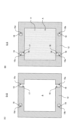
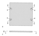
- FIG. 1 is a cross-sectional view schematically explaining a conventional alkaline water electrolytic bath 900 according to one embodiment
- FIG. 2 is a view taken along line AA in FIG.
- the up-down direction on the paper corresponds to the vertical up-down direction.
- an anode chamber cell 910 containing an anode 914 and a cathode chamber cell 920 containing a cathode 924 are arranged between an anode end unit 901e and a cathode end unit 902e via an ion permeable diaphragm 930. It comprises a plurality of structures arranged alternately.
- the electrolytic cell 900 comprises an anode end unit 901e, a cathode end unit 902e, a plurality of anode compartment cells 910 each having a conductive back partition 911 and containing an anode 914, each a conductive back partition 921; It comprises a plurality of cathode chamber cells 920 containing cathodes 924 and a plurality of ion-permeable diaphragms 930 each sandwiched at its perimeter by a gasket 940 . Between each adjacent pair of diaphragms 930 , 930 , a pair of anode chamber cell 910 and cathode chamber cell 920 are positioned such that back partition 911 and back partition 921 are adjacent.
- the anode end unit 901e comprises an anode-side press frame 961, an anode-side insulating plate 951, and an anode end cell 910e, which are arranged in order from the anode-side end of the electrolytic cell (the right side of the paper surface of FIG. 1).
- the cathode end unit 902e comprises a cathode-side press frame 962, a cathode-side insulating plate 952, and a cathode end cell 920e, which are arranged in order from the cathode-side end of the electrolytic cell (the left side of the paper surface of FIG. 1).
- the anode end cell 910e, the anode chamber cells 910, the cathode chamber cells 920, the cathode end cells 920e, and the gaskets 940 each have an anolyte supply flow section 971 at the bottom thereof, and an anode liquid/gas recovery flow section at the top thereof. 973 is provided, and the anolyte is supplied to each anode chamber A from the anolyte supply circulation portion 971, and the anolyte and the anode 914 are supplied from each anode chamber A to the anolyte/gas recovery circulation portion 973. Evolved gas is recovered.
- Catholyte end cells 920e, anode chamber cells 910, cathode chamber cells 920, and gaskets 940 are each provided with a catholyte supply flow section 972 at the bottom thereof, and a catholyte/gas recovery flow section 974 at the top thereof.
- the catholyte is supplied to each cathode chamber C from the catholyte supply circulation portion 972, and the catholyte and the gas generated at the cathode 924 are recovered from each cathode chamber C to the cathode liquid/gas recovery circulation portion 974. be done.
- An anolyte supply pipe 981 for supplying anolyte to the anolyte supply circulation portion passes through a first through hole (not shown) provided in the cathode-side press frame 962 and the cathode-side insulating plate 952 . 971.
- a catholyte supply pipe 982 for supplying the catholyte to the catholyte supply circulation portion passes through a second through hole (not shown) provided in the cathode-side press frame 962 and the cathode-side insulating plate 952 . 972.
- An anolyte/gas recovery pipe 983 for recovering the anolyte and gas from the anolyte/gas recovery passageway passes through a third through hole (not shown) provided in the cathode-side press frame 962 and the cathode-side insulating plate 952 . , and the anolyte/gas recovery flow section 973 .
- a catholyte/gas recovery pipe 984 for recovering the catholyte and gas from the catholyte/gas recovery channel is passed through a fourth through-hole (not shown) provided in the cathode-side press frame 962 and the cathode-side insulating plate 952 . , to the catholyte/gas recovery flow section 974 .
- the anode end cell 910e, each anode chamber cell 910, each cathode chamber cell 920, and cathode end cell 920e are made of metal, and are provided with an anolyte supply pipe 981, a catholyte supply pipe 982, an anolyte/gas recovery pipe 983, and a catholyte/gas recovery pipe 983.
- the gas recovery pipe 984 is also made of metal.
- An anode terminal is connected to the anode end cell 910e, and a cathode terminal is connected to the cathode end cell 920e.
- the anode-side press frame 961, the cathode-side press frame 962, the anolyte supply pipe 981, the catholyte supply pipe 982, the anolyte/gas recovery pipe 983, and the catholyte/gas recovery pipe 984 are all electrically connected for safety. grounded to
- the anolyte is continuous between the anolyte supply pipe 981, the anolyte supply circulation portion 971, each anode chamber A, the anolyte/gas recovery circulation portion 973, and the anolyte/gas recovery pipe 983, , the portions of the cathode chamber cells 920 and the cathode end cells 920e facing the anolyte supply circulation portion 971 and the anolyte/gas recovery circulation portion 973 are counter electrodes (counter electrodes) with respect to the anode 914, which is the working electrode.
- the reverse reaction of the anode reaction occurs inside the anolyte supply circulation portion 971 and the anolyte/gas recovery circulation portion 973 .
- the catholyte is continuous between the catholyte supply pipe 982, the catholyte supply conduit 972, each cathode chamber C, the catholyte/gas recovery conduit 974, and the catholyte/gas recovery conduit 984. Therefore, the portions of each of the anode chamber cells 910 and the anode end cells 910e facing the catholyte supply circulation portion 972 and the catholyte/gas recovery circulation portion 974 are counter electrodes (counter electrodes) with respect to the cathode 924, which is the working electrode. ), and the reverse reaction of the cathodic reaction occurs inside the catholyte supply flow section 972 and the catholyte/gas recovery flow section 974 . The current that flows in response to these reverse reactions is called leakage current.
- oxygen gas is generated by the main reaction (anodic reaction) in each anode chamber A, and the oxygen gas generated in each anode chamber A is recovered through the anode fluid/gas recovery passage 973. Since hydrogen gas is generated in the reverse reaction of the anodic reaction where it is recovered from the tube 983, if a leak current occurs, the hydrogen gas is mixed with the oxygen gas recovered from the anolyte/gas recovery tube 983, resulting in the oxygen being recovered. The purity of the gas is lowered.
- hydrogen gas is generated by the main reaction (cathode reaction) in each cathode chamber C, and the hydrogen gas generated in each cathode chamber C is passed through the catholyte/gas recovery passage 974 to the catholyte/gas. Since oxygen gas is generated in the reverse reaction of the cathodic reaction where it is recovered from the recovery tube 984, if a leak current occurs, the oxygen gas is mixed with the hydrogen gas recovered from the catholyte/gas recovery tube 984 and recovered. The purity of the hydrogen gas is lowered.
- the reverse reaction of the anodic reaction can occur even if the anolyte supply pipe 981 and the anolyte/gas recovery pipe 983 are used as opposite electrodes of the anode 914 . While the liquid resistance is relatively high between each anode 914 and each cathode chamber cell 920 and the cathode end cell 920e, the liquid resistance is small due to the short distance, so each cathode chamber cell 920 and the leakage current resulting from the reverse reaction in the cathode end cell 920e tends to account for a larger proportion of the total leakage current.
- the reverse reaction of the cathodic reaction can occur with the catholyte supply tube 982 and the catholyte/gas recovery tube 984 as counter electrodes to the cathodes 924, but from each cathode 924, the catholyte supply tube 982 and the catholyte/gas recovery tube 984 While the liquid resistance is relatively large between each cathode 924 and each anode chamber cell 910 and the anode end cell 910e, the liquid resistance is small due to the short distance, so each anode chamber cell Leakage currents resulting from reverse reactions in 910 and anode end cell 910e are likely to account for a larger proportion of the total leakage current.
- renewable energy production is generally unstable.
- photovoltaic power fluctuates greatly depending on the time of day and the weather.
- the power generation amount is extremely small in the morning and evening hours, and during cloudy weather and rainy weather.
- the current value of the main reaction will greatly fluctuate depending on the power supplied from the power supply.
- the leak current value does not change significantly.
- the current of the main reaction is small, so the amount of hydrogen gas and oxygen gas generated by the main reaction is small, but the leakage current value is proportional to the current value of the main reaction. Since it does not decrease as much, the amount of gas generated in the reverse reaction does not decrease significantly. As a result, the oxygen gas concentration in the obtained hydrogen gas and the hydrogen gas concentration in the obtained oxygen gas increase, and the quality of the obtained gas deteriorates. Also, depending on the conditions, the composition of the resulting gas may fall within the explosive range.
- An object of the present invention is to provide an electrolytic cell for alkaline water electrolysis that can reduce or suppress the influence of leakage current. Also provided is a gas production method using the electrolytic cell for alkaline water electrolysis.
- An electrolytic cell for obtaining oxygen and hydrogen by electrolyzing an electrolytic solution made of alkaline water It comprises a conductive first rear partition, a first flange portion provided on the outer peripheral portion of the first rear partition, and an oxygen generating anode electrically connected to the first rear partition. , an anodic end cell defining an anodic chamber; A conductive second back partition, a second flange provided on the outer periphery of the second back partition, and a cathode for hydrogen generation electrically connected to the second back partition.
- a cathode end cell defining a cathode chamber
- a plurality of diaphragm elements disposed between the anode end cell and the cathode end cell, each comprising an ion-permeable diaphragm and a protective member holding at least a peripheral edge of the diaphragm
- a conductive third back partition a third flange portion provided on the outer peripheral portion of the third back partition, and an oxygen generating anode electrically connected to the third back partition
- a plurality of anode compartment cells defining an anode compartment, each of the plurality of anode compartment cells being disposed between respective adjacent said diaphragm elements
- a conductive fourth back partition, a fourth flange portion provided on the outer peripheral portion of the fourth back partition, and a cathode for hydrogen generation electrically connected to the fourth back partition
- a plurality of cathode compartment cells defining a cathode compartment, each of the plurality of cathode compartment cells being
- the flange portion may or may not be integrally formed, the plurality of diaphragm elements includes a first diaphragm element adjacent to the anode end cell and a second diaphragm element adjacent to the cathode end cell; Diaphragm elements other than the lower portion of the first flange portion of the anode end cell, the lower portion of the third flange portion of each anode chamber cell, the lower portion of the fourth flange portion of each cathode chamber cell, and the second diaphragm element
- an anolyte supply circulation part is provided or not provided at the lower part of the second flange part of the cathode end cell and the lower part of the protective member of the second diaphragm element, each of the anode end cells and each of the anode chamber cells includes an anode liquid supply branch flow path provided in fluid communication with the anode liquid supply flow section and the anode chamber;
- the anolyte/gas recovery circulation part is provided or not provided on the upper part of the second flange part of the cathode end cell and the upper part of the protective member of the second diaphragm element,
- Each of the anode end cells and each of the anode chamber cells includes an anode fluid/gas recovery branch channel provided in fluid communication with the anode fluid/gas recovery circulation portion and the anode chamber,
- the anolyte and the gas in the anode chamber are recovered from each anode chamber through the branch passages for recovering the anolyte and the gas into the circulation portion for recovering the anolyte and the gas,
- a catholyte supply circulation part At the bottom of the protective member of is
- All or part of the surface is covered with an electrically insulating resin material, the anolyte supply circulation portion, the anolyte supply branch channel, the anolyte/gas recovery circulation portion, and the anolyte/gas recovery branch channel of the third flange portion of the anode chamber cell; all or part of each surface facing the catholyte supply flow section and the catholyte/gas recovery flow section is covered with an electrically insulating resin material; the catholyte supply circulation portion, the catholyte supply branch channel, the catholyte/gas recovery circulation portion, the catholyte/gas recovery branch channel, of the fourth flange portion of the cathode chamber cell; Alkaline water electrolysis, characterized in that all or part of each surface facing the anolyte supply circulation part and the anolyte/gas recovery circulation part is covered with an electrically insulating resin material.
- each anode chamber cell is an anolyte-supplying circulation hole and a catholyte-supplying circulation hole provided through the lower portion of the third flange portion in the stacking direction; an anode liquid/gas recovery circulation hole and a cathode liquid/gas recovery circulation hole provided through the upper portion of the third flange portion in the stacking direction; with The anode fluid supply branch channel provided in the anode chamber cell is in fluid communication with the anode chamber defined by the anode chamber cell and the anode fluid supply flow hole provided in the anode chamber cell.
- the anode fluid/gas recovery branch channel provided in the anode chamber cell is connected to the anode chamber defined by the anode chamber cell and the anode fluid/gas recovery circulation hole provided in the anode chamber cell.
- Each cathode chamber cell is an anolyte-supplying circulation hole and a catholyte-supplying circulation hole provided through the lower portion of the fourth flange portion in the stacking direction; an anode liquid/gas recovery circulation hole and a cathode liquid/gas recovery circulation hole provided through the upper portion of the fourth flange portion in the stacking direction; with The catholyte-supplying branch channel provided in the cathode chamber cell is in fluid communication with the cathode chamber defined by the cathode chamber cell and the catholyte-supplying flow hole provided in the cathode chamber cell.
- the catholyte/gas recovery branch channel provided in the cathode chamber cell is connected to the cathode chamber defined by the cathode chamber cell and the catholyte/gas recovery circulation hole provided in the cathode chamber cell.
- the first diaphragm element is an anolyte supply flow hole provided through the lower portion of the protective member in the stacking direction; an anolyte/gas recovery flow hole provided through the upper portion of the protective member in the stacking direction; with When the catholyte supply flow part is provided in the first flange part of the anode end cell
- the protective member of the first diaphragm element penetrates the lower portion of the protective member in the stacking direction.
- the second diaphragm element is a flow hole for supplying a catholyte provided through the lower portion of the protective member in the stacking direction; a catholyte/gas recovery flow hole provided through the upper portion of the protective member in the stacking direction; with When the second flange portion of the cathode end cell is provided with the anolyte supply circulation portion, the protective member of the second diaphragm element is provided so as to penetrate the lower portion of the protective member in the stacking direction.
- anolyte and gas recovery holes each of the anolyte supply through holes provided in the plurality of anode chamber cells, each of the anolyte supply through holes provided in the plurality of cathode chamber cells, and each of the anolyte provided in the plurality of diaphragm elements;
- An integrally continuous anolyte supply circulation portion formed by fluidly communicating with the supply circulation holes is formed by the anolyte supply circulation portion of the anode end cell, and the anode end cell has the anolyte supply circulation portion of the cathode end cell.
- the anolyte fluid/gas recovery circulating portion formed by fluidly communicating with the respective anolyte fluid/gas recovery circulating holes is connected to the anolyte fluid/gas recovery circulating portion of the anode end cell and the anode end cell.
- the cathode end cell When the cathode end cell is provided with an anolyte/gas recovery flow section, the anode end cell is in fluid communication with the anolyte/gas recovery flow section, Catholyte supply flow holes provided in the plurality of anode compartment cells, Catholyte supply flow holes provided in the plurality of cathode compartment cells, Catholyte supply flow holes provided in the plurality of diaphragm elements
- An integral and continuous catholyte supply passage formed by fluidly communicating with the supply passage holes includes a catholyte supply passage of the cathode end cell and a catholyte supply passage of the anode end cell.
- each catholyte/gas recovery flow hole provided in the plurality of anode chamber cells; each catholyte/gas recovery flow hole provided in the plurality of cathode chamber cells; The catholyte/gas recovery passages of the cathode end cell and the catholyte/gas recovery passages of the cathode end cell and the When the anode end cell is provided with a catholyte/gas recovery flow section, the anode end cell is further in fluid communication with the catholyte/gas recovery flow section, The anolyte supply flow hole, the catholyte supply flow hole, the anolyte/gas recovery flow hole, the catholyte/gas recovery flow hole, and the anode of the third flange portion of each anode chamber cell All or part of each surface facing the liquid supply branch channel and the anode liquid/gas recovery branch channel is covered with an electrically
- each bipolar electrolytic element is an anolyte-supplying circulation hole and a catholyte-supplying circulation hole provided through the lower portions of the third flange portion and the fourth flange portion in the stacking direction; an anode liquid/gas recovery circulation hole and a cathode liquid/gas recovery circulation hole provided through the upper portions of the third flange portion and the fourth flange portion in the stacking direction; with The anolyte supply branch channel of each bipolar electrolytic element is provided in fluid communication with the anode chamber defined by the bipolar electrolytic element and the anolyte supply flow hole provided in the bipolar electrolytic element.
- the anode fluid/gas recovery branch channel of each bipolar electrolytic element is in fluid communication with the anode chamber defined by the bipolar electrolytic element and the anode fluid/gas recovery flow hole provided in the bipolar electrolytic element.
- the catholyte supply branch channel of each bipolar electrolytic element is provided in fluid communication with the cathode chamber defined by the bipolar electrolytic element and the catholyte supply flow hole provided in the bipolar electrolytic element.
- the catholyte/gas recovery branch channel of each bipolar electrolytic element is in fluid communication with the cathode chamber defined by the bipolar electrolytic element and the catholyte/gas recovery flow hole provided in the bipolar electrolytic element.
- the first diaphragm element is an anolyte supply flow hole provided through the lower portion of the protective member in the stacking direction; an anolyte/gas recovery flow hole provided through the upper portion of the protective member in the stacking direction; with When the catholyte supply flow part is provided in the first flange part of the anode end cell, the protection member of the first diaphragm element is provided so as to penetrate the lower part of the protection member in the stacking direction.
- the protective member of the first diaphragm element penetrates the lower portion of the protective member in the stacking direction.
- the second diaphragm element is a flow hole for supplying a catholyte provided through the lower portion of the protective member in the stacking direction; a catholyte/gas recovery flow hole provided through the upper portion of the protective member in the stacking direction; with When the second flange portion of the cathode end cell is provided with the anolyte supply circulation portion, the protective member of the second diaphragm element is provided so as to penetrate the lower portion of the protective member in the stacking direction.
- anolyte-supplying hole formed by fluidly communicating the anolyte-supplying through hole provided in each bipolar electrolytic element with each of the anolyte-supplying through-holes provided in the plurality of diaphragm elements.
- the flow section is in fluid communication with the anolyte supply flow section of the anode end cell, and with the anolyte supply flow section of the cathode end cell if the cathode end cell is provided with the anolyte supply flow section. and
- An integrated continuous body formed by fluidly communicating the anolyte/gas recovery flow holes provided in each bipolar electrolytic element with the anolyte/gas recovery flow holes provided in the plurality of diaphragm elements.
- the anolyte/gas recovery circulating portion is the anolyte/gas circulating portion of the anode end cell, and when the anolyte/gas circulating portion is provided in the cathode end cell, the anode of the cathode end cell.
- An integrated and continuous catholyte-supplying channel formed by fluidly communicating the catholyte-supplying through-holes provided in each bipolar electrolytic element with the catholyte-supplying through-holes provided in the plurality of diaphragm elements.
- the flow section is in fluid communication with the catholyte supply flow section of the cathode end cell and with the catholyte supply flow section of the anode end cell if the catholyte supply flow section is provided in the anode end cell.
- the anolyte supply circulating portion, the anolyte supply branch channel, the anolyte/gas recovery circulating portion, and the anolyte/gas recovery branch of the first flange portion of the anode end cell 99.0% or more of the area of each surface facing the flow path is covered with the electrically insulating resin material
- the catholyte supply circulation part is provided in the first flange part of the anode end cell
- the area of the surface of the first flange part of the anode end cell facing the catholyte supply circulation part is 99.0% or more is covered with the electrically insulating resin material
- the catholyte/gas recovery circulation part is provided in the first flange part of the anode end cell
- the cathode liquid/gas recovery circulation part of the first flange part of the anode end cell 99.0% or more of the surface area is covered with the electrically insulating resin material
- the catholyte supply circulation part the catholyte
- the anolyte supply flow section and the anolyte/gas recovery flow section are provided through a first flange portion of the anode end cell
- the catholyte supply circulation part is also provided under the protective member of the first diaphragm element and under the first flange part of the anode end cell so as to penetrate the first flange part
- the catholyte/gas recovery flow passage is also provided above the protective member of the first diaphragm element and above the first flange portion of the anode end cell, penetrating through the first flange portion.
- An anolyte is supplied from the outside of the electrolytic cell to each anode chamber through the anolyte supply flow section provided in the anode end cell
- Catholyte is supplied from the outside of the electrolytic cell to each cathode chamber through the catholyte supply flow section provided in the anode end cell
- the anolyte and the gas in each anode chamber are taken out from each anode chamber to the outside of the electrolytic cell through the anode fluid/gas recovery flow section provided in the anode end cell, [1] to [7], wherein the catholyte and the gas in each cathode chamber are taken out from each cathode chamber to the outside of the electrolytic cell through the catholyte/gas recovery flow section provided in the anode end cell.
- the catholyte supply flow section and the catholyte/gas recovery flow section are provided through a second flange portion of the cathode end cell,
- the anolyte supply circulation part is also provided below the protective member of the second diaphragm element and below the second flange part of the cathode end cell so as to penetrate the second flange part,
- the anolyte/gas recovery passages are also provided above the protective member of the second diaphragm element and above the second flange portion of the cathode end cell, penetrating through the second flange portion.
- An anolyte is supplied from the outside of the electrolytic cell to each anode chamber through the anolyte supply flow section provided in the cathode end cell
- Catholyte is supplied from the outside of the electrolytic cell to each cathode chamber through the catholyte supply flow section provided in the cathode end cell
- the anolyte and the gas in each anode chamber are taken out of the electrolytic cell from each anode chamber through the anolyte/gas recovery flow section provided in the cathode end cell, [1] to [7], wherein the catholyte and the gas in each cathode chamber are taken out from each cathode chamber to the outside of the electrolytic cell through the catholyte/gas recovery flow section provided in the cathode end cell.
- an anode-side press frame disposed adjacent to the anode end cell; a cathode-side press frame disposed adjacent to the cathode end cell; further comprising The electrolytic cell according to any one of [1] to [10], wherein the laminated structure is sandwiched and tightened between the anode-side press frame and the cathode-side press frame.
- [12] A method for producing at least hydrogen gas by electrolyzing alkaline water, (a) A step of recovering hydrogen gas from the catholyte/gas recovery flow section by applying a fluctuating direct current to the electrolytic cell for alkaline water electrolysis according to any one of [1] to [11]. including In the step (a), the amount of hydrogen gas generated in the main reaction per unit time when the electrolytic cell is operated at the minimum value of the fluctuating direct current is equal to the maximum value of the fluctuating direct current in the electrolytic cell. is less than 15% of the amount of hydrogen gas generated in the main reaction per unit time when operated at .
- step (a) further includes recovering oxygen gas from the anolyte/gas recovery circulation section.
- the first flange portion of the anode end cell includes an anolyte supply flow section, an anolyte supply branch flow path, an anolyte/gas recovery flow section, and an anolyte/gas recovery flow section.
- each surface facing the gas recovery branch channel is covered with an electrically insulating resin material;
- all or part of the surface of the first flange portion of the anode end cell facing the catholyte supply flow portion is covered with an electrically insulating resin material; the first flange of the anode end cell
- the catholyte/gas recovery circulation part is provided in the part, all or part of the surface facing the catholyte/gas recovery circulation part of the first flange part of the anode end cell is electrically insulated.
- a catholyte supply channel a catholyte supply branch channel, a catholyte/gas recovery channel, and a catholyte/gas recovery channel of the second flange of the cathode end cell;
- an electrically insulating resin material When all or part of each surface facing the branch flow path is covered with an electrically insulating resin material;
- the second flange portion of the cathode end cell When the second flange portion of the cathode end cell is provided with an anolyte supply circulation portion all or part of the surface of the second flange portion of the cathode end cell facing the anolyte supply flow portion is covered with an electrically insulating resin material;
- the anolyte/gas recovery passage When the anolyte/gas recovery passage is provided, all or part of the surface facing the anolyte/gas recovery passage of the second flange portion of the cathode end cell is made of an electrically insulating resin.
- anolyte supply conduit, anolyte supply branch channel, anolyte/gas recovery conduit, anolyte/gas recovery branch of the third flange of the anode chamber cell All or part of each surface facing the channel, the catholyte supply channel, and the catholyte/gas recovery channel is covered with an electrically insulating resin material;
- Catholyte supply channel, catholyte supply branch channel, catholyte/gas recovery channel, catholyte/gas recovery branch channel, anolyte supply channel, and anolyte/gas channel of the flange portion All or part of each surface facing the collecting distribution section is covered with an electrically insulating resin material.
- the ion conduction resistance (liquid resistance) from the working electrode to the counter electrode is increased and/or the electrode area of the counter electrode is reduced when the reverse reaction occurs due to the leakage current. Therefore, the influence of leakage current can be reduced or suppressed.
- the electrolytic cell for alkaline water electrolysis of the present invention by using the electrolytic cell for alkaline water electrolysis of the present invention, it is possible to reduce or suppress the influence of leakage current, so that the purity is improved while using an unstable power supply. It becomes possible to produce gas with
- FIG. 3 is a cross-sectional view schematically illustrating a conventional alkaline water electrolytic bath 900;
- FIG. 2 is a view taken along the line AA in FIG. 1;
- BRIEF DESCRIPTION OF THE DRAWINGS It is sectional drawing which illustrates typically the electrolytic cell 100 which concerns on embodiment of 1 of this invention.
- 4 is a view taken along line BB of FIG. 3;
- FIG. (A) is a view of only the cathode-side press frame 62 extracted from FIG.
- FIG. (B) is a cross-sectional view taken along the line BB in (A);
- 4A is a view of only the cathode-side insulating member 52 extracted from FIG. 3;
- (B) is a cross-sectional view taken along the line BB in (A);
- (A) is a view of only the cathode end cell 20e extracted from FIG.
- (B) is a cross-sectional view taken along the line BB in (A);
- (C) is a cross-sectional view taken along line CC of (A).
- (A) is a cross-sectional view taken along line DD of FIG. 7(A).
- (B) is a view taken along line EE of FIG. 7(A).
- (A) A view of only the second diaphragm element 30C, which is a diaphragm element adjacent to the cathode end cell 20e, extracted from FIG.
- (B) is a cross-sectional view taken along the line BB in (A);
- (C) is a cross-sectional view taken along line CC of (A).
- (A) It is the figure which extracted only the anode chamber cell 10 from FIG. (B) is a cross-sectional view taken along the line BB in (A);
- (C) is a cross-sectional view taken along line CC of (A).
- (A) is a cross-sectional view taken along line DD of FIG. 10(A);
- (B) is a view taken along line EE of FIG. 10(A).
- (A) is a view of only the diaphragm elements 30 other than the first diaphragm element 30A and the second diaphragm element 30C extracted from FIG.
- (B) is a cross-sectional view taken along the line BB in (A);
- (C) is a cross-sectional view taken along line CC of (A).
- (A) It is the figure which extracted only the cathode chamber cell 20 from FIG. (B) is a cross-sectional view taken along the line BB in (A);
- (C) is a cross-sectional view taken along line CC of (A).
- (A) is a cross-sectional view along line DD of FIG. 13(A), and (B) is a view along line EE of FIG. 13(A).
- (A) is a view of only the first diaphragm element 30A, which is a diaphragm element adjacent to the anode end cell 10e, extracted from FIG.
- FIG. 16 is a cross-sectional view taken along the line BB in (A);
- C is a cross-sectional view taken along line CC of (A).
- A) is a view of only the anode end cell 10e extracted from FIG. 3;
- B) is a cross-sectional view taken along the line BB in (A);
- C) is a cross-sectional view taken along line CC of (A).
- A) is a cross-sectional view taken along line DD of FIG. 16(A);
- (B) is a view taken along line EE of FIG. 16(A).
- 4A is a view of only the anode-side insulating member 51 extracted from FIG. 3;
- (B) is a cross-sectional view taken along the line BB in (A);
- (A) is a view of only the anode end cell 210e extracted from FIG. 20;
- (B) is a cross-sectional view taken along the line BB in (A);
- (C) is a cross-sectional view taken along line CC of (A).
- (A) is a cross-sectional view taken along line DD of FIG. 24(A).
- (B) is a view taken along line EE of FIG. 24(A).
- (A) is a view of only the first diaphragm element 230A, which is a diaphragm element adjacent to the anode end cell 210e, extracted from FIG.
- (B) is a cross-sectional view taken along the line BB in (A);
- (C) is a cross-sectional view taken along line CC of (A).
- (A) is a view of only the second diaphragm element 230C, which is a diaphragm element adjacent to the cathode end cell 220e, extracted from FIG.
- (B) is a cross-sectional view taken along the line BB in (A);
- (C) is a cross-sectional view taken along line CC of (A).
- (A) is a view of only the cathode end cell 220e extracted from FIG.
- FIG. 20 is a cross-sectional view taken along the line BB in (A);
- (C) is a cross-sectional view taken along line CC of (A).
- (A) is a cross-sectional view taken along line DD of FIG. 28(A);
- (B) is a view taken along line EE of FIG. 28(A).
- 21A is a view of only a cathode-side insulating member 252 extracted from FIG. 20;
- FIG. (B) is a cross-sectional view taken along the line BB in (A);
- 21A is a view of only the cathode-side press frame 262 extracted from FIG. 20;
- FIG. (B) is a cross-sectional view taken along the line BB in (A);
- FIG. 3 is a cross-sectional view schematically illustrating an electrolytic cell 300 according to another embodiment
- 33A is a view of only the integrated pole chamber cell 310 extracted from FIG. 32
- FIG. (B) is a cross-sectional view taken along the line BB in (A)
- (A) is a cross-sectional view taken along line CC of FIG. 33(A);
- (B) is a cross-sectional view taken along line DD of FIG. 33(A).
- (A) is a cross-sectional view taken along line EE of FIG. 33(A);
- B) is a view taken along line FF of FIG. 33(A).
- A) is a cross-sectional view taken along line GG of FIG.
- FIG. 4 is a cross-sectional view schematically illustrating an electrolytic cell 400 according to another embodiment;
- (A) is a view of only the cathode end cell 420e extracted from FIG. 37;
- (B) is a cross-sectional view taken along the line BB in (A);
- (C) is a CC arrow view of (A).
- (A) is a view of only the anode end cell 410e extracted from FIG. 37;
- (B) is a cross-sectional view taken along the line BB in (A);
- (C) is a CC arrow view of (A).
- (A) is a view of only the integrated pole chamber cell 440 extracted from FIG.
- FIG. 3 is a cross-sectional view schematically explaining an electrolytic cell 500 according to another embodiment;
- a view of diaphragm element 530/530C extracted from FIG. (B) is a cross-sectional view taken along the line BB in (A);
- (C) is a CC arrow view of (A).
- A) is a view of the first diaphragm element 530A extracted from FIG.
- FIG. 6 is a cross-sectional view schematically illustrating an electrolytic cell 600 according to another embodiment;
- a view of diaphragm element 630/630C extracted from FIG. (B) is a cross-sectional view taken along the line BB in (A);
- A) is a cross-sectional view taken along line CC of FIG. 46(A);
- B) is a cross-sectional view taken along line DD of FIG. 46(A).
- A) is a view of the first diaphragm element 630A extracted from FIG.
- (B) is a cross-sectional view taken along the line BB in (A);
- (A) is a cross-sectional view taken along line CC of FIG. 48(A);
- (B) is a cross-sectional view taken along line DD of FIG. 48(A).
- (A) is a cross-sectional view showing an exploded posture of protective members 640/640C and 640A in the electrolytic bath 600;
- (B) is a cross-sectional view showing a posture in which the gasket 641 is received in the receiving portions 6421a of the base frames 6421/6421C and 6421A and supported by the support portions 6421b from the stacking direction.
- (C) is a cross-sectional view showing the posture in which the cover frame 6422 is received in the step between the surface 6421c of the base frame 6421/6421C, 6421A and the surface 641a of the gasket in (B).
- the notation " E1 and/or E2 " for the elements E1 and E2 means “ E1 or E2 , or a combination thereof", and the elements E1 , ..., EN (N is 3 above integers), the notation "E 1 , ..., E N-1 , and/or E N “ shall mean “E 1 , ..., E N-1 , or E N , or combinations thereof.” do.
- FIG. N (N is an integer of 4 or more), elements that have already appeared in FIGS. may be omitted.
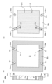
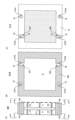
- FIG. 3 is a cross-sectional view schematically illustrating an electrolytic cell 100 according to one embodiment of the invention.
- the electrolytic cell 100 is an electrolytic cell for alkaline water electrolysis.
- 4 is a view taken along line BB of FIG. 3.
- FIG. In FIGS. 3 and 4, the up-down direction on the paper corresponds to the vertical up-down direction.
- the electrolytic cell 100 includes a conductive first rear partition wall 11e, a first flange portion 12e provided on the outer peripheral portion of the first rear partition wall 11e, and the first rear partition wall.
- an anode end-cell 10e comprising an oxygen evolution anode 14 electrically connected to 11e and defining an anode chamber A; a conductive second rear partition 21e and a peripheral portion of said second rear partition 21e. a cathode end cell 20e that defines a cathode chamber C; and an anode end cell 10e. a plurality of diaphragm elements 30, 30, . a third rear partition wall 11, a third flange portion 12 provided on the outer peripheral portion of the third rear partition wall 11, and an oxygen generating anode 14 electrically connected to the third rear partition wall defining an anode chamber A, each of said plurality of anode chamber cells 10, 10, ...
- protective member 32 is a gasket.
- the plurality of diaphragm elements 30, 30, . . . include a first diaphragm element 30A adjacent to the anode end cell 10e and a second diaphragm element 30C adjacent to the cathode end cell 20e.
- anode chamber cell 10 with the third rear partition 11 facing the anode end cell 10e side and a fourth rear partition 21 facing the cathode end cell 20e side.
- a set with one cathode chamber cell 20 is arranged such that the third rear partition 11 and the fourth rear partition 21 are adjacent to each other.
- the adjacently arranged third rear partition 11 and fourth rear partition 21 are separate (that is, not integrally formed) members.
- Each anode chamber cell 10 is joined or integrated with a third rear partition wall 11 and a peripheral edge of the third rear partition wall 11 to define an anode chamber A together with the third rear partition wall 11 and the diaphragm 31 . and conductive ribs 13, 13, .
- Each cathode chamber cell 20 is joined or integrated with a fourth rear partition wall 21 and a peripheral edge portion of the fourth rear partition wall 21 to define a cathode chamber C together with the fourth rear partition wall 21 and the diaphragm 30 . and conductive ribs 23, 23, .
- the anode end cell 10e is included in the anode end unit 101e.
- the anode end unit 101e comprises an anode-side press frame 61, an anode-side insulating member 51, and an anode end cell 10e, which are arranged in order from the anode-side end of the electrolytic cell (the right side of the paper surface of FIG. 3).
- Cathode end cell 20e is included in cathode end unit 102e.
- the cathode end unit 102e comprises a cathode-side press frame 62, a cathode-side insulating member 52, and a cathode end cell 20e, which are arranged in order from the cathode-side end of the electrolytic cell (the left side of the paper surface of FIG. 3).
- the anode end cell 10e is joined or integrated with the first rear partition wall 11e and the peripheral edge of the first rear partition wall 11e, and the first flange defines the anode chamber A together with the first rear partition wall 11e and the diaphragm 31. It has a portion 12e and a conductive rib 13 protruding from the first rear partition wall 11e, and the conductive rib 13 holds an oxygen generating anode 14.
- the cathode end cell 20e is joined or integrated with a second rear partition wall 21e and a peripheral edge portion of the second rear partition wall 21e, and a second flange defining a cathode chamber C together with the second rear partition wall 21e and the diaphragm 31. It has a portion 22e and a conductive rib 23 protruding from the second rear partition wall 21e, and the conductive rib 23 holds a cathode 24 for hydrogen generation.
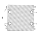
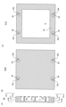
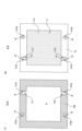
- FIG. 5(A) is a view of only the cathode-side press frame 62 extracted from FIG. 3, and FIG. 5(B) is a cross-sectional view taken along line BB of FIG. 5(A).
- the cathode-side press frame 62 has a first through hole 62a and a second through hole 62b provided in its lower portion, and a third through hole provided in its upper portion. 62c and a fourth through hole 62d.
- the cathode-side press frame 62 is a metal member, and the surfaces facing the first to fourth through holes 62a, 62b, 62c, and 62d are covered with an electrically insulating resin material 68, respectively.
- the electrically insulating resin material 68 a material similar to the electrically insulating resin materials 28, 28e, 18, 18e described later can be used.
- the preferable thickness of the coating with the electrically insulating resin material 68 is the same as the preferable thickness of the coating with the electrically insulating resin materials 28, 28e, 18, 18e, which will be described later.
- the electrically insulating resin material 68 preferably covers 99.0% or more, more preferably 99.5% or more, of the area of each surface. is more preferable, and it is most preferable to cover the entirety of each surface.
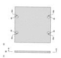
- FIG. 6(A) is a view of only the cathode-side insulating member 52 extracted from FIG. 3, and FIG. 6(B) is a cross-sectional view taken along line BB of FIG. 6(A).
- the cathode-side insulating member 52 has a first through hole 52a and a second through hole 52b provided in its lower portion, and a third through hole provided in its upper portion. 52c and a fourth through hole 52d.
- the first through-hole 52a, the second through-hole 52b, the third through-hole 52c, and the fourth through-hole 52d of the cathode-side insulating member 52 are the first through-holes of the cathode-side press frame 62. It communicates with the hole 62a, the second through hole 62b, the third through hole 62c, and the fourth through hole 62d.
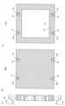
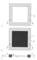
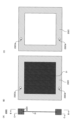
- FIG. 7(A) is a view of only the cathode end cell 20e extracted from FIG. 3
- FIG. 7(B) is a cross-sectional view taken along line BB of FIG. 7(A)
- FIG. 7(C) is a view of FIG. A) CC arrow sectional view
- FIG. 8(A) is a DD arrow sectional view of FIG. 7(A)
- FIG. 8(B) is an EE arrow view of FIG. 7(A) be.
- the conductive ribs 23 and cathodes 24 are omitted. As shown in FIGS. 7(B) and (C) and FIGS.
- the cathode end cell 20e further includes a catholyte-supplying branch channel 26e provided in fluid communication with the catholyte-supplying circulation portion 22eb and the cathode chamber C.
- the catholyte is supplied to the cathode chamber C from the catholyte supply circulation portion 25eb through the catholyte supply branch channel 26e.
- the cathode end cell 20e further includes a catholyte/gas recovery branch channel 27e provided in fluid communication with the catholyte/gas recovery circulation portion 25ed and the cathode chamber C.
- the catholyte and the gas in the cathode chamber are recovered from the cathode chamber C through the branch flow path 27e to the catholyte/gas recovery circulation portion 25ed. As shown in FIGS. 7(B) and (C) and FIGS.
- the surface of the second flange portion 22e of the cathode end cell 20e facing the anolyte supply circulation portion 25ea, the catholyte The surface facing the supply circulation part 25eb, the surface facing the anode liquid/gas recovery circulation part 25ec, the surface facing the catholyte/gas recovery circulation part 22ed, the surface facing the catholyte supply branch channel 26e , and the surface facing the catholyte/gas recovery branch channel 27e are each covered with an electrically insulating resin material 28e.
- the thickness of the coating of the electrically insulating resin material 28e is preferably 50 ⁇ m or more, more preferably 100 ⁇ m or more, and still more preferably 300 ⁇ m or more, from the viewpoint of ensuring electrical insulation and mechanical strength. , also, from the viewpoint of coating thickness accuracy and coating construction cost, it is preferably 1500 ⁇ m or less, more preferably 1000 ⁇ m or less, and still more preferably 800 ⁇ m or less. It can be 800 ⁇ m. Moreover, it is most preferable that the electrically insulating resin material 28e covers the entire surface. may not be covered with the electrically insulating resin material 28e.
- the electrically insulating resin material 28e preferably covers 99.0% or more of the area of each of the surfaces, and covers 99.0% of the area of each of the surfaces. It is more preferable to cover 5% or more.
- an electrically insulating resin material having alkali resistance can be preferably used as the electrically insulating resin material 28e. Examples of such resin materials include natural rubber (NR), styrene-butadiene rubber (SBR), chloroprene rubber (CR), butadiene rubber (BR), acrylonitrile-butadiene rubber (NBR), ethylene-propylene rubber (EPT).
- Elastomers such as ethylene-propylene-diene rubber (EPDM), isobutylene-isoprene rubber (IIR), chlorosulfonated polyethylene rubber (CSM); rigid vinyl chloride resin, polypropylene resin, polyethylene resin, nylon resin, polyacetal resin, amorphous Polyester resin, polyetheretherketone resin, polyetherimide resin, polyphenylene sulfide resin, polybenzimidazole resin, polytetrafluoroethylene resin, tetrafluoroethylene-perfluoroalkyl vinyl ether copolymer resin, tetrafluoroethylene-ethylene copolymer Resins, tetrafluoroethylene-hexafluoropropylene copolymers, and the like can be mentioned.
- EPDM ethylene-propylene-diene rubber
- IIR isobutylene-isoprene rubber
- CSM chlorosulfonated polyethylene rubber
- rigid vinyl chloride resin polypropylene resin, poly
- a layer of a material having alkali resistance may be provided by coating or the like on the surface of the resin material.
- a method of covering the surface of the second flange portion 22e of the cathode end cell 20e with the electrically insulating resin material 28e the surface of the second flange portion 22e of the cathode end cell 20e is covered with the anolyte supply circulation portion 25ea.
- a surface facing the catholyte supply flow section 25eb; a surface facing the anode liquid/gas recovery flow section 25ec; a surface facing the catholyte/gas recovery flow section 22ed; 26e and the surface facing the catholyte/gas recovery branch channel 27e can be coated with the resin material.
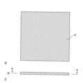
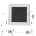
- FIG. 9(A) is a view of only the second diaphragm element 30C, which is a diaphragm element adjacent to the cathode end cell 20e, extracted from FIG. 3, and FIG. 9(C) is a cross-sectional view taken along line CC of FIG. 9(A).
- the second diaphragm element 30C includes an ion-permeable diaphragm 31 and a protective member 32C that holds at least the periphery of the diaphragm 31.
- an anolyte supply flow section 32Ca and a catholyte supply flow section 32Cb are provided below the protective member 32C of the second diaphragm element 30C.
- An anolyte/gas recovery circulation portion 32Cc and a catholyte/gas recovery circulation portion 32Cd are provided above the protective member 32C of the second diaphragm element 30C.
- protective member 32C is a gasket, and is made of an electrically insulating resin material.
- the anolyte supply circulation portion 32Ca of the second diaphragm element 30C communicates with the anolyte supply circulation portion 25ea of the cathode end cell 20e.
- the catholyte supply circulation portion 32Cb of the second diaphragm element 30C communicates with the catholyte supply circulation portion 25eb of the cathode end cell 20e.
- anode liquid/gas recovery circulation portion 32Cc of the second diaphragm element 30C communicates with the anode liquid/gas recovery circulation portion 25ec of the cathode end cell 20e.
- the catholyte/gas recovery circulation portion 32Cd of the second diaphragm element 30C communicates with the catholyte/gas recovery circulation portion 25ed of the cathode end cell 20e.
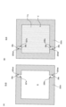
- FIG. 10(A) is a view of only the anode chamber cell 10 extracted from FIG. 3, FIG. 10(B) is a cross-sectional view taken along line BB of FIG. 10(A), and FIG. 10(C) is a cross-sectional view of FIG. (A) is a cross-sectional view along the CC arrow, FIG. 11(A) is a cross-sectional view along the DD arrow in FIG. 10(A), and FIG. 11(B) is a cross-sectional view along the EE arrow in FIG. is.
- the conductive ribs 13 and the anodes 14 are omitted. As shown in FIGS.
- anode chamber cell 10 under the third flange portion 12 of the anode chamber cell 10, an anolyte supply flow portion 15a and a catholyte A supply circulation portion 15b is provided.
- an anolyte/gas recovery circulation portion 15c and a cathode liquid/gas recovery circulation portion 15d are provided.
- the anode chamber cell 10 includes an anode liquid supply branch passage 16 provided in fluid communication with the anode chamber A and an anode liquid supply flow section 15a.
- the anolyte is supplied to the anode chamber A from the anolyte supply circulation portion 15 a through the anolyte supply branch passage 16 .
- the anode chamber cell 10 includes an anode liquid/gas recovery branch passage 17 provided in fluid communication with the anode liquid/gas recovery circulation portion 15c and the anode chamber A. Through the flow path 17, the anode liquid and the gas in the anode chamber are recovered from the anode chamber A to the anode liquid/gas recovery circulation portion 15c. As shown in FIGS. 10B and 10C and FIGS.
- the surface of the third flange portion 12 of the anode chamber cell 10 facing the anolyte supply flow portion 15a The surface facing the liquid supply branch channel 16, the surface facing the anolyte/gas recovery flow channel 15c, the surface facing the anolyte/gas recovery branch channel 17, the surface facing the catholyte supply flow channel 15b
- the surface facing the catholyte/gas recovery circulation portion 15d is covered with an electrically insulating resin material 18, respectively.
- the electrically insulating resin material 18 materials similar to those described above for the electrically insulating resin material 28e can be used.
- the same method as described above as the method for providing the resin material 28e on the flange portion 22e of the cathode end cell 20e can be adopted.
- the preferable thickness of the coating with the electrically insulating resin material 18 is the same as the preferable thickness of the coating with the electrically insulating resin material 28e described above.
- the electrically insulating resin material 18 preferably covers 99.0% or more of the area of each of the surfaces, and covers 99.0% of the area of each of the surfaces. It is more preferable to cover 5% or more.
- FIG. 12(A) is a view of only each diaphragm element 30 other than the first diaphragm element 30A and the second diaphragm element 30C extracted from FIG. 3, and FIG. 12(C) is a cross-sectional view taken along line CC of FIG. 12(A).
- each diaphragm element 30 includes an ion-permeable diaphragm 31 and a protective member 32 that holds at least the periphery of the diaphragm 31 .
- an anolyte supply flow section 32a and a catholyte supply flow section 32b are provided under the protection member 32 of the diaphragm element 30, an anolyte supply flow section 32a and a catholyte supply flow section 32b are provided.
- an anolyte/gas recovery circulation portion 32c and a catholyte/gas recovery circulation portion 32d are provided on the upper portion of the protective member 32 of the diaphragm element 30 .
- the protective member 32 is a gasket and is made of an electrically insulating resin material.
- FIG. 13(A) is a view of only the cathode chamber cell 20 extracted from FIG. 3
- FIG. 13(B) is a cross-sectional view taken along line BB of FIG. 13(A)
- FIG. 13(C) is a cross-sectional view of FIG. (A) is a cross-sectional view along the CC arrow
- FIG. 14(A) is a cross-sectional view along the DD arrow in FIG. 13(A)
- FIG. 14(B) is a cross-sectional view along the EE arrow in FIG. is.
- the conductive ribs 23 and the cathode 24 are omitted. As shown in FIGS.
- the cathode chamber cell 20 further includes a catholyte supply branch channel 26 provided in fluid communication with the cathode chamber C and the catholyte supply circulation portion 25b.
- the catholyte is supplied to the cathode chamber C from the catholyte supply circulation portion 25b through the catholyte supply branch channel 26 .
- the cathode chamber cell 20 further includes a catholyte/gas recovery branch channel 27 provided in fluid communication with the catholyte/gas recovery circulation portion 25d and the cathode chamber C.
- the catholyte and the gas in the cathode chamber are recovered from the cathode chamber C through the recovery branch channel 27 to the catholyte/gas recovery circulation portion 25d.
- the surface of the fourth flange portion 22 of the cathode chamber cell 20 facing the anolyte supply circulation portion 25a, the cathode The surface facing the liquid supply circulation portion 25b, the surface facing the anode liquid/gas recovery circulation portion 25c, the surface facing the catholyte/gas recovery circulation portion 22d, and the catholyte supply branch channel 26
- the surface and the surface facing the catholyte/gas recovery branch channel 27 are each covered with an electrically insulating resin material 28 .
- the electrically insulating resin material 28 materials similar to those described above for the resin material 28e can be used.
- the same method as described above as the method for providing the resin material 28e on the flange portion 22e of the cathode end cell 20e can be adopted.
- the preferable thickness of the coating with the electrically insulating resin material 28 is the same as the preferable thickness of the coating with the electrically insulating resin material 28e described above. It is most preferable that the electrically insulating resin material 28 cover the entire surface, but if the effect of reducing the influence of the leakage current is not significantly impaired, the resin material 28 may partially cover the surface. It does not have to be covered with the electrically insulating resin material 28 .
- the electrically insulating resin material 28 preferably covers 99.0% or more of the area of each of the surfaces, and covers 99.0% of the area of each of the surfaces. It is more preferable to cover 5% or more.
- FIG. 15(A) is a diagram of only the first diaphragm element 30A, which is a diaphragm element adjacent to the anode end cell 10e, extracted from FIG. 3, and FIG. 15(C) is a cross-sectional view taken along line CC of FIG. 15(A).
- the first diaphragm element 30A includes an ion-permeable diaphragm 31 and a protective member 32A that holds at least the periphery of the diaphragm 31.
- an anolyte supply flow section 32Aa is provided, but a catholyte supply flow section is not provided.
- an anolyte/gas recovery flow passage 32Ac is provided on the upper portion of the protective member 32A of the first diaphragm element 30A, but a catholyte/gas recovery passage is not provided.
- the protective member 32A is a gasket and is made of an electrically insulating resin material.
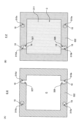
- FIG. 16(A) is a view of only the anode end cell 10e extracted from FIG. 3
- FIG. 16(B) is a cross-sectional view taken along line BB of FIG. A) CC arrow sectional view
- FIG. 17(A) is a DD arrow sectional view of FIG. 16(A), FIG. be.
- the conductive ribs 13 and the anodes 14 are omitted in FIGS. 16(B) and (C) and FIGS. 17(A) and (B).
- an anolyte supply circulation portion 15ea is provided below the first flange portion 12e of the anode end cell 10e.
- anode fluid/gas recovery circulation portion 15ec is provided on the upper portion of the first flange portion 12e of the anode end cell 10e, but a cathode fluid/gas recovery circulation portion is not provided.
- the anode end cell 10e includes an anolyte-supplying branch channel 16e provided in fluid communication with the anolyte-supplying circulation portion 15ea and the anode chamber A, An anolyte is supplied to the anode chamber A from the anolyte supply circulation portion 15ea through the anolyte supply branch channel 16e.
- anode end cell 10e is provided with an anode liquid/gas recovery branch flow path 17e provided in fluid communication with the anode liquid/gas recovery circulation portion 15ec and the anode chamber A.
- the anolyte and the gas in the anode chamber are recovered from the anode chamber A through the passage 17e to the anolyte/gas recovery passage portion 15ec.
- the surface facing the supply branch flow path 16e, the surface facing the anolyte/gas recovery circulation portion 15ec, and the surface facing the anolyte/gas recovery branch flow path 17e are each made of an electrically insulating resin. It is covered with material 18e.
- the electrically insulating resin material 18e the same materials as those described above as the electrically insulating resin material 28e can be used.
- the same method as described above as the method for providing the resin material 28e on the flange portion 22e of the cathode end cell 20e can be employed.
- the preferable thickness of the coating with the electrically insulating resin material 18e is the same as the preferable thickness of the coating with the electrically insulating resin material 28e described above. It is most preferable that the electrically insulating resin material 18e covers the entire surface, but if the effect of reducing the influence of the leakage current is not greatly impaired, the resin material 18e may cover a part of the surface. It does not have to be covered with the electrically insulating resin material 18e.
- the electrically insulating resin material 18e preferably covers 99.0% or more of the area of each of the surfaces, and covers 99.0% of the area of each of the surfaces. It is more preferable to cover 5% or more.
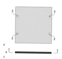
- FIG. 18(A) is a view of only the anode-side insulating member 51 extracted from FIG. 3, and FIG. 18(B) is a cross-sectional view taken along line BB of FIG. 18(A).
- the anode-side insulating member 51 includes an anolyte supply flow section, a catholyte supply flow section, an anolyte/gas recovery flow section, and a catholyte/gas recovery flow section. It does not have a through hole communicating with either.
- FIG. 19(A) is a view of only the anode-side press frame 61 extracted from FIG. 3, and FIG. 19(B) is a cross-sectional view taken along line BB of FIG. 19(A).
- the anode-side press frame 61 includes an anode liquid supply circulation section, a cathode liquid supply circulation section, an anode liquid/gas recovery circulation section, and a cathode liquid/gas recovery circulation section. It does not have a through hole communicating with either.
- the anolyte supply passages 32 a of the diaphragm elements 30 other than the second diaphragm element 30 ⁇ /b>C are in fluid communication with each other to form an integrated anolyte supply passage 71 .
- the anode liquid/gas recovery circulation portion 15ec of the anode end cell 10e, the anode liquid/gas recovery circulation portion 15c of each anode chamber cell 10, and the anode liquid/gas recovery circulation portion 25c of each cathode chamber cell 20 are provided.
- anolyte fluid/gas recovery flow passages 32c of the diaphragm elements 30 other than the first diaphragm element 30A and the second diaphragm element 30C are in fluid communication with each other to form an integral anolyte fluid/gas recovery flow passage. 73 is formed.
- the catholyte supply flow portion 15b of each anode chamber cell 10 the catholyte supply flow portion 25b of each cathode chamber cell 20, the catholyte supply flow portion 25eb of the cathode end cell 20e, and the second diaphragm element
- the catholyte supply circulation portion 32Cb of 30C and the catholyte supply circulation portion 32b of each diaphragm element 30 other than the first diaphragm element 30A and the second diaphragm element 30C are in fluid communication with each other to form an integrated cathode.
- a liquid supply circulation portion 72 is formed.
- the catholyte/gas recovery circulation portion 15d of each anode chamber cell 10 the cathode liquid/gas recovery circulation portion 25d of each cathode chamber cell 20, and the cathode liquid/gas recovery circulation portion 25ed of the cathode end cell 20e.
- the catholyte/gas recovery circulation portion 32Cd of the second diaphragm element 30C and the catholyte/gas recovery circulation portion 32d of each diaphragm element 30 other than the first diaphragm element 30A and the second diaphragm element 30C. They are in fluid communication with each other to form an integral catholyte/gas recovery conduit 74 .
- An anode liquid supply pipe 81 for supplying the anode liquid to the anode liquid supply circulation section 71 is provided in the cathode side press frame 62 and the cathode side insulating member 52 so as to communicate with the anode liquid supply circulation section 71 . Through the holes 62a, 52a, it is connected to the anolyte supply circulation portion 71 (see FIGS. 3 to 6).
- a catholyte supply pipe 82 for supplying catholyte to the catholyte supply passage 72 is provided in the cathode side press frame 62 and the cathode side insulating member 52 so as to communicate with the catholyte supply passage 72 .
- An anolyte/gas recovery pipe 83 for recovering anolyte and gas from the anolyte/gas recovery circulating portion 73 communicates with the anolyte/gas recovering circulating portion 73 through the cathode-side press frame 62 and the cathode-side insulating member 52 .
- Through the third through holes 62c, 52c provided in the anolyte/gas recovery flow section 73 see FIGS. 3 to 6).
- a catholyte/gas recovery pipe 84 for recovering the catholyte and gas from the catholyte/gas recovery circulation portion 74 communicates with the cathode side press frame 62 and the cathode side insulating member 52 with the cathode liquid/gas recovery circulation portion 74 .
- a rigid conductive material having alkali resistance can be used without particular limitation.
- Simple metals such as ordinary steel (i.e. low carbon steel and medium carbon steel), carbon steel such as high carbon steel, steel such as stainless steel (such as SUS304, SUS310, SUS310S, SUS316, SUS316L, etc.), etc.
- a metal material can be preferably employed. These metal materials may be used after being plated with nickel in order to improve corrosion resistance and conductivity.
- a rigid material having alkali resistance can be used without particular limitation.
- Metal metal materials such as carbon steel such as ordinary steel (that is, low carbon steel and medium carbon steel), high carbon steel, etc., stainless steel (such as SUS304, SUS310, SUS310S, SUS316, SUS316L, etc.), etc. are preferred. can be adopted.
- the metal material may be plated with nickel in order to improve corrosion resistance.
- the first rear partition wall 11e and the first flange portion 12e of the anode end cell 10e may be joined by welding, adhesion, or the like, or may be integrally formed of the same material.
- the second rear partition wall 21e and the second flange portion 22e of the cathode end cell 20e may be joined by welding, adhesion, or the like, or may be integrally formed of the same material.
- the third rear partition wall 11 and the third flange portion 12 of each anode chamber cell 10 may be joined by welding, adhesion, or the like, or may be integrally formed of the same material.
- the fourth rear partition wall 21 and the fourth flange portion 22 of each cathode chamber cell 20 may be joined by welding, adhesion, or the like, or may be integrally formed of the same material.
- the first rear partition wall 11e and the first flange portion 12e of the anode end cell 10e are made of the same conductive material (for example, the metal material described above) in that the resistance to the pressure inside the pole chamber can be easily increased.
- the third back partition 11 and the third flange portion 12 of each anode chamber cell 10 are preferably integrally formed of the same conductive material (for example, the above-mentioned metal material), and each cathode chamber It is preferable that the fourth rear partition wall 21 and the fourth flange portion 22 of the cell 20 are integrally formed of the same conductive material (for example, the metal material described above).
- an anode that can be used in an electrolytic cell for alkaline water electrolysis can be used without particular limitation.
- Anode 14 typically comprises a conductive substrate and a catalyst layer coating the surface of the substrate.
- the catalyst layer is preferably porous.
- the conductive substrate of anode 14 can be, for example, nickel, nickel alloys, nickel iron, vanadium, molybdenum, copper, silver, manganese, platinum group elements, graphite, or chromium, or combinations thereof.
- a conductive substrate made of nickel can be preferably used for the anode 14 .
- the catalyst layer contains nickel as an element.
- the catalyst layer preferably comprises nickel oxide, nickel metal, or nickel hydroxide, or combinations thereof, and may comprise alloys of nickel with one or more other metals. It is particularly preferred that the catalyst layer consists of metallic nickel.
- the catalyst layer may further contain chromium, molybdenum, cobalt, tantalum, zirconium, aluminum, zinc, platinum group elements, rare earth elements, or combinations thereof. Rhodium, palladium, iridium, or ruthenium, or a combination thereof, may be further supported on the surface of the catalyst layer as an additional catalyst.
- the conductive substrate of anode 14 may be a rigid substrate or a flexible substrate. Examples of the rigid conductive base material that constitutes the anode 14 include expanded metal and punched metal. As a flexible conductive base material that constitutes the anode 14, for example, a wire mesh woven (or knitted) with metal wires can be used.
- cathode 24 As the cathode 24 for hydrogen generation (hereinafter sometimes simply referred to as "cathode 24"), a cathode that can be used in an electrolytic cell for alkaline water electrolysis can be used without particular limitation.
- Cathode 24 typically comprises a conductive substrate and a catalyst layer coating the surface of the substrate.
- the conductive substrate of the cathode 24 for example, nickel, nickel alloy, stainless steel, mild steel, nickel alloy, or nickel-plated surface of stainless steel or mild steel can be preferably used.
- the catalyst layer of the cathode 24 a catalyst layer made of noble metal oxides, nickel, cobalt, molybdenum, or manganese, oxides thereof, or noble metal oxides can be preferably used.
- the conductive substrate that constitutes the cathode 24 may be, for example, a rigid substrate or a flexible substrate.
- the rigid conductive base material that constitutes the cathode 24 include expanded metal and punched metal.
- a flexible conductive base material that constitutes the cathode 24 for example, a wire mesh woven (or knitted) with metal wires can be used.
- the conductive ribs 13 and 23 known conductive ribs used in alkaline water electrolytic baths can be used without particular limitation.
- the conductive ribs 13 protrude from the rear partition walls 11 of the anode chamber cells 10 and the anode end cells 10e, and the conductive ribs 23 protrude from the rear partition walls 21 of the cathode chamber cells 20 and the cathode end cells 20e. is provided.
- the connection method, shape, number and arrangement of the conductive ribs 13 are not particularly limited.
- the connection method, shape, number and arrangement of the conductive ribs 23 are not particularly limited.
- any rigid conductive material having alkali resistance can be used without particular limitation, such as single metals such as nickel and iron; ), carbon steel such as high carbon steel, and steel such as stainless steel (for example, SUS304, SUS310, SUS310S, SUS316, SUS316L, etc.) can be preferably employed. These metal materials may be plated with nickel in order to improve their corrosion resistance and electrical conductivity.
- an ion-permeable diaphragm 31 that can be used in an electrolytic cell for alkaline water electrolysis can be used without particular limitation. It is desirable that the diaphragm 31 have low gas permeability, low electrical conductivity, and high strength.
- the diaphragm 31 include a porous membrane made of asbestos or modified asbestos, a porous diaphragm using a polysulfone-based polymer, a cloth using a polyphenylene sulfide fiber, a fluorine-based porous membrane, an inorganic material and an organic material.
- a porous membrane such as a porous membrane using a hybrid material containing both of
- an ion exchange membrane such as a fluorine-based ion exchange membrane can also be used as the diaphragm 31 .
- the protective members 32, 32A, 32C are made of gaskets.
- gaskets constituting the protective members 32, 32A, and 32C gaskets that can be used in electrolytic cells for alkaline water electrolysis and have electrical insulation properties can be used without particular limitation.
- FIG. 3 shows a cross section of the gasket.
- the protective member 32 has a flat shape and holds the peripheral edge of the diaphragm 31 while protecting the flange 12 (or 12e) of the adjacent anode chamber cell 10 (or anode end cell 10e) and the cathode chamber cell 20 (or cathode). It is sandwiched between the flange portion 22 (or 22e) of the end cell 20e).
- the gasket that constitutes the protective member 32 is preferably made of an electrically insulating elastomer having alkali resistance.
- electrically insulating elastomers include natural rubber (NR), styrene-butadiene rubber (SBR), chloroprene rubber (CR), butadiene rubber (BR), acrylonitrile-butadiene rubber (NBR), ethylene-propylene rubber. (EPT), ethylene-propylene-diene rubber (EPDM), isobutylene-isoprene rubber (IIR), chlorosulfonated polyethylene rubber (CSM) and the like.
- a layer of a material having alkali resistance may be provided by coating or the like on the surface of the gasket material.
- the anode-side insulating member 51 and the cathode-side insulating member 52 see FIGS. 3, 6, and 18; hereinafter sometimes simply referred to as "insulating members 51 and 52"
- the anode end cell and the Any insulating member that can be used for electrical insulation between the anode-side press frame and electrical insulation between the cathode end cell and the cathode-side press frame can be used without particular limitation.
- Examples of materials for the insulating members 51 and 52 include rigid vinyl chloride resin, polypropylene resin, polyethylene resin, nylon resin, polyacetal resin, amorphous polyester resin, polyetheretherketone resin, polyetherimide resin, polyphenylene sulfide resin, Polybenzimidazole resin, polytetrafluoroethylene resin, tetrafluoroethylene-perfluoroalkyl vinyl ether copolymer resin, tetrafluoroethylene-ethylene copolymer resin and the like can be mentioned.
- the anode-side press frame 61 and the cathode-side press frame 62 are fastened by tie rods (not shown) to form an anode. Insulating members 51 and 52, anode chamber cells 10 and anode end cells 10e, cathode chamber cells 20 and cathode end cells 20e, and diaphragm elements 30 (including first diaphragm element 30A and second diaphragm element 30C).
- the press frames 61 and 62 are made of a metal material having rigidity to withstand the fastening load. Examples of the metal material forming the press frames 61 and 62 include carbon steel such as SS400 and stainless steel such as SUS304 and SUS316.
- the electrolytic cell 100 it is possible to increase the ionic conduction resistance (liquid resistance) from the working electrode to the counter electrode and/or reduce the electrode area of the counter electrode when the reverse reaction occurs due to the leakage current. It becomes possible to reduce or suppress the influence of the current.
- An anolyte supply pipe 81, a catholyte supply pipe 82, an anolyte/gas recovery pipe 83, and a catholyte/gas recovery pipe 84 (hereinafter collectively referred to as "anolyte supply/recovery pipe”), respectively.
- metal materials that constitute the anolyte supply pipe 81, the catholyte supply pipe 82, the anolyte/gas recovery pipe 83, and the catholyte/gas recovery pipe 84 include carbon steel such as SS400, SUS304, SUS310, SUS316, and the like.
- Tetrafluoroethylene-perfluoroalkyl vinyl ether is used as the electrically insulating resin that coats the inner surfaces of the anolyte supply pipe 81, the catholyte supply pipe 82, the anolyte/gas recovery pipe 83, and the catholyte/gas recovery pipe 84.
- Resin materials having electrical insulation and alkali resistance such as copolymer resins and tetrafluoroethylene-ethylene copolymer resins, can be used without particular limitations.
- the anolyte supply pipe 81, the catholyte supply pipe 82, the anolyte/gas recovery pipe 83, and the catholyte/gas recovery pipe 84 are respectively formed through the first through holes 62a, 52a, the second through holes 62b, 52b, and the second through holes 62b, 52b. 3 through-holes 62c, 52c and fourth through-holes 62d, 52d (hereinafter collectively referred to as "each through-hole”), the anolyte supply flow section 71 and the catholyte supply flow section, respectively.
- anolyte supply/recovery circulation unit For example, known connection methods such as threaded connection, socket welding, butt welding, flange connection, etc. can be used without particular limitation.
- the area of the cross section perpendicular to the longitudinal direction of the pipe.) (unit: m 2 ) is not particularly limited, but is preferably 100 m/m 2 or more, more It is preferably 1,000 m/m 2 or more.
- the upper limit is not particularly limited, but may be, for example, less than 20,000 m/m 2 .
- the length of the shortest path inside the bent metal tube can be determined, for example, by passing the thread through the metal tube over the entire length of the metal tube and pulling the thread from both ends so that there is no slack in the thread. known as length.
- length the length of the shortest path inside the bent metal tube
- cross-sectional area if the cross-sectional area varies depending on the location inside the pipe, the maximum value shall be adopted.
- An anode terminal is connected to the anode end cell 10e, and a cathode terminal is connected to the cathode end cell 20e.
- the anode-side press frame 61, the cathode-side press frame 62, the anolyte flow pipe 81, the catholyte supply pipe 82, the anolyte/gas recovery pipe 83, and the catholyte/gas recovery pipe 84 are all electrically grounded. ing.
- the anolyte is supplied at the connection between the anolyte supply pipe 81 and the anolyte supply circulation portion 71 and at the connection between the anolyte solution/gas recovery pipe 83 and the anolyte/gas recovery circulation portion 73:
- the catholyte is supplied to the catholyte supply pipe at the connecting portion between the catholyte supply pipe 82 and the catholyte supply circulation portion 72 and at the connection portion between the catholyte/gas recovery pipe 84 and the catholyte/gas recovery circulation portion 74.
- the electrolytic cell 100 is particularly effective in suppressing leak current when an unstable power source is used as a direct current source. From such a point of view, the amount of hydrogen gas generated in the main reaction per unit time when the electrolytic cell of the present invention is operated at the minimum current is the same as the unit time when the electrolytic cell of the present invention is operated at the maximum current preferably less than 15%, more preferably less than 10%, still more preferably less than 5%, in one embodiment 1% or more, in another embodiment can be 2% or more.
- the terms "maximum current” and “minimum current” mean the maximum and minimum values of the current that flows through the electrolytic cell.
- an electrolytic cell 100 an electrolytic system comprising the electrolytic cell 100 and a DC current source that supplies a DC current to the electrolytic cell
- a DC current source that supplies a DC current to the electrolytic cell
- each anolyte supply channel and recovery channel for supplying the anolyte to the electrolytic cell and recovering the anolyte and the gas from the electrolytic cell flexible hoses or other resin pipes are branched from each electrode chamber to a collective pipe. If a long channel length is ensured for the branched channel by using it in the channel, the liquid resistance to the leakage current can be easily increased.
- resin pipes such as flexible hoses are convenient in terms of handling of pipes.
- each anolyte supply channel and recovery channel is also pressurized, so that each anolyte supply channel and recovery channel or each branch channel is flexible. It is difficult to use a resin pipe such as a hose in terms of strength. Therefore, from the viewpoint of strength, in an electrolytic cell that performs electrolysis under pressurized conditions, the through-holes passing through the flange portions of the metal electrolytic cells are communicated with each other to form an integrated anolyte supply circulation portion. , a catholyte supply channel, an anolyte/gas recovery channel, and a catholyte/gas recovery channel, respectively.
- the metal member constituting the flange portion of each electrolytic cell is exposed facing each circulation portion. Therefore, it is difficult to increase the liquid resistance against leakage current by securing a long channel length from the working electrode to the counter electrode, since the metal member exposed to each flow path acts as a counter electrode.
- the electrolytic cell 100 the through-holes penetrating through the flange portions of the metallic electrolytic cells are communicated with each other to form the integral circulation portions. Even when performing electrolysis, it is possible to reduce or suppress the influence of leak current. In addition, even when electrolysis is performed using an unstable power source as a DC current source that supplies DC current to the electrolytic cell, it is possible to reduce or suppress the influence of leak current.
- the pressure inside the cathode chamber is preferably 20 kPa or higher, more preferably 400 kPa or higher, relative to the atmospheric pressure. More preferably, the pressure is 800 kPa or higher.
- the upper limit of the pressure inside the cathode chamber depends on the strength of the members constituting the electrolytic cell, it can be, for example, less than atmospheric pressure +3000 kPa.
- the pressure inside the cathode chamber is equal to or higher than the above lower limit value
- the compression ratio in the pressurization step after recovering the hydrogen gas from the cathode chamber can be reduced or the pressurization step can be omitted, thereby reducing equipment costs and It is possible to save space and save energy for the entire facility.
- the effect of reducing the electrolysis voltage can be obtained by setting the pressure inside the cathode chamber to be equal to or higher than the above lower limit. It is considered that this is due to the fact that the air bubble resistance between the anode and the cathode decreases due to the smaller size of air bubbles generated in the cathode chamber.
- the pressure inside the anode chamber is preferably 20 kPa or higher, more preferably 400 kPa or higher, relative to the atmospheric pressure. is more preferable, and a high pressure of 800 kPa or more is even more preferable.
- the upper limit of the pressure inside the anode chamber depends on the strength of the members constituting the electrolytic cell, it can be, for example, less than atmospheric pressure +3000 kPa.
- the compression ratio in the pressure increasing step after recovering the oxygen gas from the anode chamber can be reduced or the pressure increasing step can be omitted, thereby further reducing equipment costs. , it is possible to achieve further space saving and energy saving for the entire facility.
- the effect of reducing the electrolysis voltage can be obtained by setting the pressure inside the anode chamber to be equal to or higher than the above lower limit. It is believed that this is due to the fact that the air bubble resistance between the anode and the cathode is further reduced by reducing the size of air bubbles generated in the anode chamber.
- the difference between the pressure inside the cathode chamber and the pressure inside the anode chamber is, for example, preferably less than 5.0 kPa, more preferably less than 1.0 kPa.
- the difference between the pressure inside the cathode chamber and the pressure inside the anode chamber is less than the above upper limit value, the gas permeates the diaphragm due to the pressure difference between the anode chamber and the cathode chamber and flows from the anode chamber to the cathode chamber.
- each of the anolyte supply/recovery pipes 81-84 is connected to the first through fourth through holes 62a/52a-62d/52d provided in the cathode-side press frame 62 and the cathode-side insulating member 52.
- the electrolytic cell 100 is connected to the anode liquid supply/recovery flow sections 71 to 74 through the electrodes, the present invention is not limited to this embodiment.
- one or more of the anolyte supply pipes/recovery pipes are connected to the corresponding anolyte supply/recovery passages through through-holes provided in the anode-side press frame and the anode-side insulating member. It is also possible to set it as the electrolytic cell of a form.
- FIG. 20 is a cross-sectional view schematically explaining an electrolytic cell 200 according to such another embodiment.
- the electrolytic bath 200 is an electrolytic bath for alkaline water electrolysis.
- 21 is a view taken along line BB of FIG. 20.
- elements that have already appeared in FIGS. 3-19 are assigned the same reference numerals as those in FIGS. 3-19, and description thereof is omitted.
- the electrolytic cell 200 includes an anode end unit 201e in place of the anode end unit 101e, a cathode end unit 202e in place of the cathode end unit 102e, and the cathode end unit 201e is provided with anode liquid supply/recovery tubes 81 to 84. It differs from the electrolytic cell 100 in that it is connected.
- the anode end unit 201e includes an anode end cell 210e instead of the anode end cell 10e, an anode side insulating member 251 instead of the anode side insulating member 51, and an anode side press frame 261 instead of the anode side press frame 61. , is different from the anode end unit 101e.
- the cathode end unit 202e includes a cathode end cell 220e instead of the cathode end cell 20e, a cathode side insulating member 252 instead of the cathode side insulating member 52, and a cathode side press frame 262 instead of the cathode side press frame 62. , is different from the cathode end unit 102e.
- the cathode side press frame 262 differs from the cathode side press frame 62 in that it does not have the first to fourth through holes 62a to 62d.
- the cathode-side insulating member 252 differs from the cathode-side insulating member 52 in that it does not have the first to fourth through holes 52a to 52d.
- FIG. 22(A) is a view of only the anode-side press frame 261 extracted from FIG. 20, and FIG. 22(B) is a cross-sectional view taken along line BB of FIG. 22(A).
- the anode-side press frame 261 has a first through hole 261a and a second through hole 261b provided in its lower portion, and a third through hole provided in its upper portion. 261c and a fourth through hole 261d.
- the anode-side press frame 261 is a metal member, and the surfaces facing the first to fourth through holes 261a to 261d are covered with an electrically insulating resin material 68, respectively.
- the same material as the anode-side press frame 61 described above can be used.
- the electrically insulating resin material 68 can be configured in the same manner as the electrically insulating resin material 68 in the electrolytic cell 100 described above, and its preferred embodiment is also the same as described above.
- FIG. 23(A) is a view of only the anode-side insulating member 251 extracted from FIG. 20, and FIG. 23(B) is a cross-sectional view taken along line BB of FIG. 23(A).
- the anode-side insulating member 251 has a first through hole 251a and a second through hole 251b provided in its lower portion, and a third through hole provided in its upper portion. 251c and a fourth through hole 251d.
- the first to fourth through holes 52a, 52b, 52c and 52d of the anode side insulating member 251 correspond to the first to fourth through holes 62a, 62b, 62c and 62d of the anode side press frame 261. , are in communication with each other.
- As a material constituting the anode-side insulating member 251 the same material as that of the anode-side insulating member 51 described above can be used.
- FIG. 24(A) is a view of only the anode end cell 210e extracted from FIG. 20, FIG. 24(B) is a cross-sectional view taken along line BB of FIG. 24(A), and FIG. A) CC arrow sectional view, FIG. 25(A) is a DD arrow sectional view of FIG. 24(A), FIG. be.
- the conductive ribs 13 and the anodes 14 are omitted.
- the anode end cell 210e differs from the anode end cell 10e (FIGS. 3, 16, 17) in that it has a first flange portion 212e instead of the first flange portion 12e.
- the same material as that for the first flange portion 12e of the anode end cell 10e described above can be used.
- an anolyte supply flow portion 215ea and a catholyte supply flow portion 215ea are provided under the first flange portion 212e of the anode end cell 210e.
- a flow section 215eb is provided under the first flange portion 212e of the anode end cell 210e.
- anode liquid/gas recovery circulation part 215ec and a cathode liquid/gas recovery circulation part 215ed are provided on the upper part of the first flange part 212e of the anode end cell 210e.
- the anode end cell 210e includes an anode liquid supply branch channel 216e provided in fluid communication with the anode liquid supply circulation part 215ea and the anode chamber A, An anolyte is supplied to the anode chamber A from the anolyte supply circulation portion 215ea through the anolyte supply branch channel 216e.
- anode end cell 210e is provided with an anode liquid/gas recovery branch flow path 217e provided in fluid communication with the anode liquid/gas recovery circulation portion 215ec and the anode chamber A.
- anode liquid/gas recovery branch flow path 217e provided in fluid communication with the anode liquid/gas recovery circulation portion 215ec and the anode chamber A.
- the path 217e Through the path 217e, the anode liquid and the gas in the anode chamber are recovered from the anode chamber A to the anode liquid/gas recovery circulation portion 215ec.
- the surface of the first flange portion 212e of the anode end cell 210e facing the anolyte supply circulation portion 215ea The surface facing the supply branch channel 216e, the surface facing the anolyte/gas recovery flow channel 215ec, the surface facing the anolyte/gas recovery branch channel 217e, and the catholyte supply flow channel 215eb
- the surface and the surface facing the catholyte/gas recovery circulation portion 215ed are each covered with an electrically insulating resin material 18e.
- the preferable thickness of the coating of the electrically insulating resin material 18e in the anode end cell 210e is the same as the preferable thickness of the coating of the electrically insulating resin material 18e in the electrolytic cell 100 described above. It is most preferable that the electrically insulating resin material 18e covers all of the surfaces of the anode end cell 210e. A part of each of the above surfaces of may not be covered with the electrically insulating resin material 18 . From the viewpoint of enhancing the effect of reducing the influence of leakage current, the electrically insulating resin material 18 preferably covers 99.0% or more of the area of each surface of the anode end cell 210e. It is more preferable to cover 99.5% or more of each.
- FIG. 26(A) is a view of only the first diaphragm element 230A, which is a diaphragm element adjacent to the anode end cell 210e, extracted from FIG. 20, and FIG. 26(C) is a cross-sectional view taken along line CC of FIG. 26(A).
- the first diaphragm element 230A includes an ion-permeable diaphragm 31 and a protective member 232A that holds at least the peripheral portion of the diaphragm 31.
- the first diaphragm element 230A differs from the above-described first diaphragm element 30A (FIGS.
- protective member 232A is a gasket, and is made of an electrically insulating resin material. As a material constituting the protection member 232A, the same material as that of the protection member 32A described above can be used.
- FIG. 27(A) is a view of only the second diaphragm element 230C, which is a diaphragm element adjacent to the cathode end cell 220e, extracted from FIG. 20, and FIG. 27(C) is a cross-sectional view taken along line CC of FIG. 27(A).
- the second diaphragm element 230C includes an ion-permeable diaphragm 31 and a protective member 232C that holds at least the peripheral edge of the diaphragm 31.
- the second diaphragm element 230C differs from the above-described second diaphragm element 30C (FIGS.
- protective member 232C is a gasket, and is made of an electrically insulating resin material. As a material constituting the protection member 232C, the same material as that of the protection member 32C described above can be used.
- FIG. 28(A) is a view of only the cathode end cell 220e extracted from FIG. 20, FIG. 28(B) is a cross-sectional view taken along line BB of FIG. 28(A), and FIG. A) CC arrow sectional view, FIG. 29(A) is a DD arrow sectional view of FIG. 28(A), FIG. be.
- the conductive ribs 23 and the cathodes 24 are omitted.
- the cathode end cell 220e differs from the above-described cathode end cell 20e (FIGS.
- a second flange portion 222e is provided instead of the second flange portion 22e.
- a material forming the second flange portion 222e the same material as the second flange portion 22e described above can be used.
- a catholyte supply flow portion 225eb is provided below the second flange portion 222e of the cathode end cell 220e. However, no anolyte supply passage is provided.
- a catholyte/gas recovery circulation part 225ed is provided on the upper part of the second flange part 222e of the cathode end cell 220e, but an anode liquid/gas recovery circulation part is not provided.
- the cathode end cell 220e includes a catholyte supply branch channel 226e provided in fluid communication with the catholyte supply circulation portion 225eb and the cathode chamber C, The catholyte is supplied to the cathode chamber C from the catholyte supply circulation portion 225eb through the catholyte supply branch channel 226e.
- the cathode end cell 220e is provided with a catholyte/gas recovery branch channel 227e provided in fluid communication with the cathode liquid/gas recovery circulation portion 225ed and the cathode chamber C.
- a catholyte/gas recovery branch channel 227e provided in fluid communication with the cathode liquid/gas recovery circulation portion 225ed and the cathode chamber C.
- the surface facing the supply branch channel 226e, the surface facing the catholyte/gas recovery circulation part 225ed, and the surface facing the catholyte/gas recovery branch channel 227e are each made of an electrically insulating resin. It is covered with material 28e.
- the preferable thickness of the coating of the electrically insulating resin material 28e in the cathode end cell 220e is the same as the preferable thickness of the coating of the electrically insulating resin material 28e in the electrolytic cell 100 described above.
- the electrically insulating resin material 28e covers all of the surfaces of the cathode end cell 220e. It is not necessary that part of each of the surfaces of is covered with the electrically insulating resin material 28e. From the viewpoint of enhancing the effect of reducing the influence of leakage current, the electrically insulating resin material 28e preferably covers 99.0% or more of the area of each surface of the cathode end cell 220e. It is more preferable to cover 99.5% or more of each.
- FIG. 30(A) is a view of only the cathode-side insulating member 252 extracted from FIG. 20, and FIG. 30(B) is a cross-sectional view taken along line BB of FIG. 30(A).
- the cathode-side insulating member 252 includes an anolyte supply flow section, a catholyte supply flow section, an anolyte/gas recovery flow section, and a catholyte/gas recovery flow section. It does not have a through hole communicating with either.
- a material for forming the cathode-side insulating member 252 the same material as that for the cathode-side insulating member 52 described above can be used.
- FIG. 31(A) is a view of only the cathode-side press frame 262 extracted from FIG. 20, and FIG. 31(B) is a cross-sectional view taken along line BB of FIG. 31(A).
- the cathode-side press frame 262 includes an anode liquid supply circulation section, a cathode liquid supply circulation section, an anode liquid/gas recovery circulation section, and a cathode liquid/gas recovery circulation section. It does not have a through hole communicating with either.
- As a material for forming the cathode-side press frame 262 the same material as that for the cathode-side press frame 62 described above can be used.
- the anolyte/gas recovery circulation portion 215ec of the anode end cell 210e, the anode liquid/gas recovery circulation portion 15c of each anode chamber cell 10, and the anode fluid/gas recovery circulation portion 25c of each cathode chamber cell 20 are provided.
- the anolyte/gas recovery circulation portion 32Ac of the first diaphragm element 30A and the anolyte/gas recovery circulation portion 32c of each diaphragm element 30 other than the first diaphragm element 230A and the second diaphragm element 230C They are in fluid communication with each other to form an integrated anolyte/gas recovery conduit 273 .
- the catholyte supply flow portion 215eb of the anode end cell 210e, the catholyte supply flow portion 15b of each anode chamber cell 10, the catholyte supply flow portion 25b of each cathode chamber cell 20, and the cathode of the cathode end cell 220e A liquid supply flow portion 225eb, a catholyte supply flow portion 232Ab of the first diaphragm element 230A, a catholyte supply flow portion 232Cb of the second diaphragm element 230C, the first diaphragm element 230A and the second diaphragm element 230A.
- the catholyte supply circulation portion 32b of each diaphragm element 30 other than the diaphragm element 230C is in fluid communication with each other to form an integrated catholyte supply circulation portion 272.
- the catholyte/gas recovery circulation portion 215ed of the anode end cell 210e, the catholyte/gas recovery circulation portion 15d of each anode chamber cell 10, and the cathode liquid/gas recovery circulation portion 25d of each cathode chamber cell 20 are provided.
- the catholyte/gas recovery passage 32 d of the diaphragm element 30 is in fluid communication with each other to form an integral catholyte/gas recovery passage 274 .
- the anode-side press frame 261 and the anode-side insulating member 251 are provided with the anode-side press frame 261 and the anode-side insulating member 251 so as to communicate with the anode-liquid supply circulation portion 271 .
- the catholyte supply pipe 82 for supplying the catholyte to the catholyte supply passage 272 is provided in the anode side press frame 261 and the anode side insulating member 251 so as to communicate with the catholyte supply passage 272 .
- An anolyte/gas recovery pipe 83 for recovering anolyte and gas from the anolyte/gas recovery circulating portion 273 communicates with the anode-side press frame 261 and the anode-side insulating member 251 with the anolyte/gas recovering circulating portion 273 . 20 to 23, through the third through holes 261c and 251c provided in the anolyte/gas recovery flow section 273. As shown in FIGS.
- a catholyte/gas recovery pipe 84 for recovering the catholyte and gas from the catholyte/gas recovery circulation section communicates with the anode side press frame 261 and the anode side insulating member 251 with the cathode liquid/gas recovery circulation section 274 . Through the provided fourth through-holes 261d and 251d, it is connected to the catholyte/gas recovery circulation portion 274 (FIGS. 20 to 23).
- An anode terminal is connected to the anode end cell 210e, and a cathode terminal is connected to the cathode end cell 220e.
- the anode-side press frame 261, the cathode-side press frame 262, the anolyte flow pipe 81, the catholyte supply pipe 82, the anolyte/gas recovery pipe 83, and the catholyte/gas recovery pipe 84 are all electrically grounded. ing.
- the electrolytic cell 200 it is possible to increase the ionic conduction resistance (liquid resistance) from the working electrode to the counter electrode and/or reduce the electrode area of the counter electrode when the reverse reaction occurs due to the leakage current, so that the leakage It becomes possible to reduce or suppress the influence of the current.
- the anolyte is supplied at the connection between the anolyte supply pipe 81 and the anolyte supply circulation portion 271 and at the connection between the anolyte solution/gas recovery pipe 83 and the anolyte/gas recovery circulation portion 273.
- the catholyte is supplied to the catholyte supply pipe at the connecting portion between the catholyte supply pipe 82 and the catholyte supply circulation portion 272 and at the connection portion between the catholyte/gas recovery pipe 84 and the catholyte/gas recovery circulation portion 274.
- an electrolytic cell 200 it is possible to further increase the ionic conduction resistance (liquid resistance) from the working electrode to the counter electrode when the reverse reaction occurs due to the leakage current, so even when an unstable power supply is used, However, it is possible to further reduce or suppress the influence of leakage current.
- the anolyte is supplied from the outside of the electrolytic cell to each anode chamber A through the anolyte supply circulation portion 25ea (71) provided in the cathode end cell 20e.
- the anolyte and the gas in each anode chamber A are taken out from the anode chamber A to the outside of the electrolytic cell through the anolyte/gas recovery circulation portion 25ec (73), and supplied to the catholyte supply provided in the cathode end cell 20e.
- Catholyte is supplied to each cathode chamber C from the outside of the electrolytic cell through the flow passage 25eb (72) for the electrolytic cell, and the catholyte and each cathode chamber C are supplied through the flow passage 25ed for recovering the catholyte and gas provided in the cathode end cell 20e.
- the gas inside the electrolytic cell 100 is taken out from each cathode chamber C to the outside of the electrolytic cell;
- the liquid is supplied to each anode chamber A, and the anode liquid and the gas in each anode chamber A are supplied from each anode chamber A to the electrolytic cell through the anode liquid/gas recovery circulation portion 215ec (273) provided in the anode end cell 210e.
- the catholyte is supplied from the outside of the electrolytic cell to each cathode chamber C through the catholyte supply flow part 215eb (272) provided in the anode end cell 210e, and the catholyte provided in the anode end cell 210e
- the electrolytic cell 200 in which the catholyte and the gas in each cathode chamber C are taken out from each cathode chamber C to the outside of the electrolytic cell through the gas recovery circulation part 215ed (274) was taken as an example, but this The invention is not limited to these forms.
- the anolyte and the gas in each anode chamber A are transferred from each anode chamber A to the outside of the electrolytic cell through an anolyte/gas recovery flow section provided in the anode end cell instead of the cathode end cell 20e.
- the electrolytic cell in a modified form so that it can be taken out at
- a modification is made such that the anolyte is supplied from the outside of the electrolytic cell to each of the anode chambers A through an anolyte supply flow section provided in the anode end cell instead of the cathode end cell 20e.
- An electrolytic bath is also possible.
- the catholyte and the gas in each cathode chamber C are transferred from each cathode chamber C to the electrolytic cell through a catholyte/gas recovery flow section provided in the anode end cell instead of the cathode end cell 20e. It is also possible to make the electrolytic cell in a modified form so that it can be taken out to the outside. Further, for example, it is also possible to combine two or more alterations selected from these and apply them to the electrolytic cell 100 .
- the catholyte and the gas in each cathode chamber C are transferred from each cathode chamber C to the electrolytic cell through a catholyte/gas recovery flow section provided in the cathode end cell instead of the anode end cell 210e. It is also possible to make the electrolytic cell in a modified form so that it can be taken out to the outside. Further, for example, in the electrolytic cell 200, a modification is made such that the catholyte is supplied from the outside of the electrolytic cell to each cathode chamber C through a catholyte supply flow section provided in the cathode end cell instead of the anode end cell 210e. An electrolytic bath is also possible.
- the anolyte and the gas in each anode chamber A are transferred from each anode chamber A to the electrolytic cell through an anolyte/gas recovery flow section provided in a cathode end cell instead of the anode end cell 210e. It is also possible to make the electrolytic cell in a modified form so that it can be taken out to the outside. Further, for example, it is also possible to combine two or more alterations selected from these and apply them to the electrolytic cell 200 .
- the anolyte may be supplied from the outside of the electrolytic cell to each anode chamber A through the anolyte supply flow section provided in the anode end cell, and through the anolyte supply flow section provided in the cathode end cell, It may be supplied to each anode chamber A from the outside of the electrolytic cell.
- the catholyte may be supplied from the outside of the electrolytic cell to each cathode chamber C through a catholyte supply flow section provided in the cathode end cell, or may be supplied to each cathode chamber C through a catholyte supply flow section provided in the anode end cell.
- Each cathode chamber C may be supplied from outside the cell.
- each anode chamber A may be taken out from each anode chamber A to the outside of the electrolytic cell through an anolyte/gas recovery flow passage provided in the anode end cell, or may be taken out of the electrolytic cell provided in the cathode end cell. It may be taken out from each anode chamber A to the outside of the electrolytic cell through the anolyte/gas recovery flow section.
- the first flange portion of the anode end cell is provided with the catholyte supply flow portion
- the surface of the first flange portion of the anode end cell facing the catholyte supply flow portion must be electrically insulating. of resin material.
- the surface of the first flange portion of the anode end cell facing the catholyte/gas recovery passage portion is , covered with an electrically insulating resin material.
- the surface of the second flange portion of the cathode end cell facing the anolyte supply passage portion is electrically insulating. of resin material.
- the surface of the second flange portion of the cathode end cell facing the anode liquid/gas recovery circulation portion is , covered with an electrically insulating resin material.
- the electrolytic cell of the form in which the third rear partition wall 11 of the anode chamber cell 10 and the fourth rear partition wall 21 of the cathode chamber cell 20, which are adjacent to each other without sandwiching the diaphragm element 30, are separate members.
- 100 and 200 are given as examples, the present invention is not limited to these forms.
- FIG. 32 is a cross-sectional view schematically explaining an electrolytic cell 300 according to such another embodiment.
- the electrolytic bath 300 is an electrolytic bath for alkaline water electrolysis.
- the up-down direction on the page corresponds to the vertical up-down direction.
- the electrolytic cell 300 differs from the electrolytic cell 100 (FIG. 3) in that instead of the set of the anode chamber cell 10 and the cathode chamber cell 20, an integrated pole chamber cell (bipolar electrolytic element) 310 is provided.
- FIG. 33(A) is a view of only the integrated pole chamber cell 310 extracted from FIG. 32
- FIG. 33(B) is a cross-sectional view taken along line BB of FIG. 33(A)
- FIG. 33(A) is a cross-sectional view along CC arrows
- FIG. 34(B) is a cross-sectional view along DD arrows in FIG. 33(A)
- FIG. 35(A) is an EE arrow in FIG. 33(A).
- 35(B) is a FF arrow view of FIG. 33(A)
- FIG. 36(A) is a GG arrow directional view of FIG. 33(A)
- FIG. 33(A) is a view taken along line HH.
- the conductive ribs 13, 23, anode 14, and the cathode 24 are omitted.
- the back partition 11 of the anode chamber cell 10 and the back partition 21 of the cathode chamber cell 20 are integrally formed to form an integral back partition 311 .
- the rear partition wall 311 As a material forming the rear partition wall 311, the same material as the rear partition walls 11 and 21 described above can be used.
- the flange portion 12 of the adjacent anode chamber cell 10 and the flange portion 22 of the cathode chamber cell 20 are integrally formed so that the anode chamber side of the rear partition wall 311 (FIGS. 20 and 33 ( A) and the cathode chamber side (right side of the paper of FIGS. 20 and 33A).
- anolyte supply flow portion 315a and a catholyte supply flow portion 315b are provided so as to penetrate the flange portion 312 in the stacking direction.
- An anode liquid/gas recovery circulation part 315c and a cathode liquid/gas recovery circulation part 315d are provided in the upper part of the flange part 312 of the integrated pole chamber cell 310 so as to penetrate the flange part 312 in the stacking direction. ing. As shown in FIGS.
- the integrated electrode chamber cell 310 includes an anolyte supply branch passage 316 provided in fluid communication with the anolyte supply circulation portion 315a and the anode chamber A. , and the anolyte is supplied to the anode chamber A from the anolyte supply circulation portion 315 a through the anolyte supply branch channel 316 .
- the integrated anode chamber cell 310 also includes an anode fluid/gas recovery branch channel 317 provided in fluid communication with the anode fluid/gas recovery circulation portion 315c and the anode chamber A.
- the integrated pole chamber cell 310 includes a catholyte supply branch channel 326 provided in fluid communication with the catholyte supply flow portion 315b and the cathode chamber C. , and the catholyte is supplied to the cathode chamber C from the catholyte supply circulation portion 315 b through the catholyte supply branch channel 326 .
- the cathode chamber cell 20 further includes a catholyte/gas recovery branch channel 327 provided in fluid communication with the catholyte/gas recovery circulation portion 315d and the cathode chamber C.
- the catholyte and the gas in the cathode chamber are recovered from the cathode chamber C through the recovery branch channel 327 to the catholyte/gas recovery circulation portion 315d.
- the surface of the flange portion 312 of the integrated pole chamber cell 310 facing the anolyte supply circulation portion 315a, the surface facing the anolyte/gas recovery circulation portion 315c, and the surface facing the anolyte supply branch channel 316 , the surface facing the anolyte/gas recovery branch channel 317, the surface facing the catholyte supply circulation part 315b, the surface facing the catholyte/gas recovery circulation part 315d, the catholyte supply branch channel 326 and the surface facing the catholyte/gas recovery branch channel 327 are each covered with an electrically insulating resin material 18 .
- the same method as described above for providing the resin material 28e on the flange portion 22e of the cathode end cell 20e can be employed.
- the preferred thickness of the coating of the electrically insulating resin material 18 on each surface of the integrated pole chamber cell 310 is the same as the thickness of each anode chamber cell 10 and each cathode chamber cell 20 of the electrolytic cells 100 and 200 described above. is the same as the preferred thickness of the coating with the electrically insulating resin material 18, 28 in .
- the electrically insulating resin material 18 covers all of the surfaces of the integrated pole chamber cell 310, but the effect of reducing the influence of leakage current is greatly impaired. A part of each surface of the integrated pole chamber cell 310 may not be covered with the electrically insulating resin material 18 as long as it is not covered with the insulating resin material 18 . From the viewpoint of enhancing the effect of reducing the influence of leakage current, the electrically insulating resin material 18 preferably covers 99.0% or more of the area of each surface of the integrated pole chamber cell 310. More preferably, they each cover 99.5% or more of the surface area.
- the anolyte supply circulation portion 32a is in fluid communication with the anolyte supply circulation portion 32a to form an integrated anolyte supply circulation portion 371.
- the anode liquid/gas recovery circulation portion 15ec of the anode end cell 10e As shown in FIG.
- the anolyte/gas recovery passage portion 32Ac of the first diaphragm element 30A the anolyte/gas recovery passage portion 32Cc of the second diaphragm element 30C, the first diaphragm element 30A and the second diaphragm element 30C.
- the anolyte/gas recovery circulation portions 32 c of the diaphragm elements 30 other than the above are in fluid communication with each other to form an integrated anolyte/gas recovery circulation portion 373 .
- the catholyte supply flow portion 315b of each integrated pole cell 310, the catholyte supply flow portion 25eb of the cathode end cell 20e, the catholyte supply flow portion 32Cb of the second diaphragm element 30C, the first The catholyte supply passage 32b of each diaphragm element 30 other than the diaphragm element 30A and the second diaphragm element 30C are in fluid communication with each other to form an integrated catholyte supply passage 372. As shown in FIG.
- a catholyte/gas recovery circulation portion 315d of each integral pole cell 310, a catholyte/gas recovery circulation portion 25ed of the cathode end cell 20e, and a catholyte/gas recovery circulation portion of the second diaphragm element 30C are provided.
- the portion 32Cd and the catholyte/gas recovery passage portion 32d of each diaphragm element 30 other than the first diaphragm element 30A and the second diaphragm element 30C are in fluid communication with each other to form an integrated catholyte/gas recovery flow path.
- a circulation portion 374 is formed.
- the anode liquid supply pipe 81 for supplying the anode liquid to the anode liquid supply circulation section 371 is provided in the cathode side press frame 62 and the cathode side insulating member 52 to communicate with the anode liquid supply circulation section 371 . Through the holes 62a, 52a, it is connected to the anolyte supply circulation part 371. As shown in FIG.
- the catholyte supply pipe 82 for supplying the catholyte to the catholyte supply circulation portion 372 is provided in the cathode side press frame 62 and the cathode side insulating member 52 so as to communicate with the catholyte supply circulation portion 372 .
- An anolyte/gas recovery pipe 83 for recovering anolyte and gas from the anolyte/gas recovery circulating portion 373 communicates with the anolyte/gas recovering circulating portion 373 through the cathode-side press frame 62 and the cathode-side insulating member 52 .
- a catholyte/gas recovery pipe 84 for recovering the catholyte and gas from the catholyte/gas recovery circulation portion 374 communicates with the cathode side press frame 62 and the cathode side insulating member 52 with the cathode liquid/gas recovery circulation portion 374 . Through the fourth through holes 62d, 52d provided at the same time, it is connected to the catholyte/gas recovery circulation portion 374. As shown in FIG.
- the present invention is not limited to this form.
- the surfaces of the anode end cells, the cathode end cells, the anode chamber cells, the cathode chamber cells, and/or the flange portions of the integrated pole chamber cells that contact the diaphragm element or the gasket are further covered with an electrically insulating resin material. It is also possible to use an electrolytic cell in the form of
- FIG. 37 is a cross-sectional view schematically explaining an electrolytic cell 400 according to such another embodiment.
- the electrolytic bath 400 is an electrolytic bath for alkaline water electrolysis.
- the up-down direction on the page corresponds to the vertical up-down direction.
- the electrolytic cell 400 includes an anode end cell 410e instead of the anode end cell 10e, a cathode end cell 420e instead of the cathode end cell 20e, and an integrated electrode chamber cell 410 instead of the integrated electrode chamber cell 310. Differs from tank 300 (FIGS. 32-36).
- FIG. 38(A) is a view of only the cathode end cell 420e extracted from FIG. 37
- FIG. 38(B) is a cross-sectional view taken along line BB of FIG. 38(A)
- FIG. A) is a CC arrow view.
- the conductive ribs 23 and cathodes 24 are omitted.
- the cathode end cell 420e differs from the cathode end cell 20e (FIGS. 3, 7, 8, 32) in that it has a flange portion 422e instead of the flange portion 22e.
- the flange portion 422e of the cathode end cell 420e is further covered with an electrically insulating resin material 28e on the surface in contact with (the protective member 32C of) the second diaphragm element 30C. is different from As a method for covering the surface of the flange portion 422e in contact with the second diaphragm element 30C with the electrically insulating resin material 28e, a technique such as coating can be adopted as described above. Also, the preferable range of the thickness of the coating of the electrically insulating resin material 28e on the surface is the same as described above.
- the electrically insulating resin material 28e is applied to the surface of the flange portion 422e of the cathode end cell 20e that contacts the second diaphragm element 30C (protective member 32C).
- 99.0% or more of the area is covered, more preferably 99.5% or more, and most preferably the entire surface.
- FIG. 39(A) is a view of only the anode end cell 410e extracted from FIG. 37
- FIG. 39(B) is a cross-sectional view taken along line BB of FIG. 39(A)
- FIG. A) is a CC arrow view.
- the conductive ribs 13 and the anodes 14 are omitted.
- the anode end cell 410e differs from the anode end cell 10e (FIGS. 3, 16, 17, 32) in that it has a flange portion 412e instead of the flange portion 12e.
- the flange portion 412e of the anode end cell 410e has a surface that contacts the first diaphragm element 30A (protective member 32A thereof) and is further covered with an electrically insulating resin material 18e. is different from As a method for covering the surface of the flange portion 412e in contact with the first diaphragm element 30A with the electrically insulating resin material 18e, a technique such as coating can be adopted as described above. Also, the preferable range of the thickness of the coating of the electrically insulating resin material 18e on the surface is the same as described above.
- the electrically insulating resin material 18e is applied to the surface of the flange portion 412e of the anode end cell 410e that contacts the first diaphragm element 30A (protective member 32A).
- 99.0% or more of the area is covered, more preferably 99.5% or more, and most preferably the entire surface.
- FIG. 40(A) is a view of only the integrated pole chamber cell 440 extracted from FIG. 37
- FIG. 40(B) is a cross-sectional view taken along line BB of FIG. 40(A) CC arrow view
- FIG. 41(A) is a DD arrow cross-sectional view of FIG. 40(A)
- FIG. 41(B) is an EE arrow view of FIG. 40(A) It is a diagram.
- the conductive ribs 13, 23, the anode 14, and the cathode 24 are omitted.
- Integral pole chamber cell 440 differs from integral pole chamber cell 310 (FIGS.
- the flange portion 442 of the integral pole chamber cell 440 is similar to the flange portion 442 of the integral pole chamber cell 310 in that the surfaces in contact with the diaphragm elements 30 (30A, 30C) are further covered with the electrically insulating resin material 18. 312 is different.
- a technique such as coating can be adopted as described above.
- the preferable range of the thickness of the coating of the electrically insulating resin material 18 on the surface is the same as described above.
- the electrically insulating resin material 18 is applied to the surfaces of the flange portion 442 of the integral pole chamber cell 440 that come into contact with the diaphragm elements 30 (30A, 30C). It is preferable to cover 99.0% or more of the area, more preferably to cover 99.5% or more of the area, and most preferably to cover the entire surface.
- the anolyte supply circulation portion 32 a is in fluid communication with the anode fluid supply circulation portion 471 to form an integrated anolyte supply circulation portion 471 .
- anode liquid/gas recovery circulation portion 15ec of the anode end cell 410e the anode liquid/gas recovery circulation portion 315c of each of the integrated pole chamber cells 440, and the anode liquid/gas recovery circulation portion 25ec of the cathode end cell 420e.
- the anolyte/gas recovery passage portion 32Ac of the first diaphragm element 30A the anolyte/gas recovery passage portion 32Cc of the second diaphragm element 30C, the first diaphragm element 30A and the second diaphragm element 30C.
- the anolyte/gas recovery circulation portions 32 c of the diaphragm elements 30 other than the above are in fluid communication with each other to form an integrated anolyte/gas recovery circulation portion 473 .
- the catholyte supply flow portion 315b of each integrated pole chamber cell 440, the catholyte supply flow portion 25eb of the cathode end cell 420e, the catholyte supply flow portion 32Cb of the second diaphragm element 30C, the first The catholyte supply passages 32b of the diaphragm elements 30 other than the diaphragm element 30A and the second diaphragm element 30C are in fluid communication with each other to form an integrated catholyte supply passage 472 .
- each integrated pole chamber cell 440 the catholyte/gas recovery flow section 315d of each integrated pole chamber cell 440, the catholyte/gas recovery flow section 25ed of the cathode end cell 420e, and the catholyte/gas recovery flow of the second diaphragm element 30C.
- the portion 32Cd and the catholyte/gas recovery passage portion 32d of each diaphragm element 30 other than the first diaphragm element 30A and the second diaphragm element 30C are in fluid communication with each other to form an integrated catholyte/gas recovery flow path.
- a circulation portion 474 is formed.
- the anode liquid supply pipe 81 for supplying the anode liquid to the anode liquid supply circulation section 471 is provided in the cathode side press frame 62 and the cathode side insulating member 52 to communicate with the anode liquid supply circulation section 471 . Through the holes 62a, 52a, it is connected to the anolyte supply circulation part 471. As shown in FIG. A catholyte supply pipe 82 for supplying catholyte to the catholyte supply passage 472 is provided in the cathode-side press frame 62 and the cathode-side insulating member 52 so as to communicate with the catholyte supply passage 472 .
- An anolyte/gas recovery pipe 83 for recovering anolyte and gas from the anolyte/gas recovery circulating portion 473 communicates with the cathode-side press frame 62 and the cathode-side insulating member 52 with the anolyte/gas recovering circulating portion 473 .
- the anode fluid/gas recovery flow part 473 is connected.
- a catholyte/gas recovery pipe 84 for recovering the catholyte and gas from the catholyte/gas recovery circulation portion 474 communicates with the cathode side press frame 62 and the cathode side insulating member 52 with the cathode liquid/gas recovery circulation portion 474 . Through the fourth through holes 62d and 52d provided on the bottom, the catholyte/gas recovery circulation portion 474 is connected.
- the electrolytic bath 400 having such a configuration, it is possible to obtain the same effects as those described above for the electrolytic bath 100 (FIGS. 3 to 19). Furthermore, according to the electrolytic cell 400 of such a configuration, the contact portion between the flange portion 412 of the anode end cell 410e and the first diaphragm element 30A and the contact portion between the flange portion 422 of the cathode end cell 420e and the second diaphragm element 30C and the contacts between the flange portion 442 of each integral pole chamber cell 440 and the two diaphragm elements 30, 30 adjacent to the integral pole chamber cell 440, these contacts remain intact. Since it acts as a counter electrode to reduce or suppress the progress of the reverse reaction, it is possible to further reduce or suppress the influence of the leak current.
- the electrolytic cells 100, 200, 300, 400 having the diaphragm element 30 (30A, 30C) provided with the protective member 32 made of a gasket were exemplified, but the present invention is limited to this form. not.
- FIG. 42 is a cross-sectional view schematically explaining an electrolytic cell 500 according to such another embodiment.
- the electrolytic bath 500 is an electrolytic bath for alkaline water electrolysis.
- the up-down direction on the paper corresponds to the vertical up-down direction.
- Electrolytic bath 500 differs from electrolytic bath 100 (FIGS. 3 to 19) in that diaphragm elements 530, 530A, and 530C are provided instead of diaphragm elements 30, 30A, and 30C, respectively.
- Diaphragm elements 530, 530A and 530C differ from diaphragm elements 30, 30A and 30C, respectively, in that protective members 532, 532A and 532C are provided instead of protective members 32, 32A and 32C.
- FIG. 43(A) is a view of the diaphragm element 530/530C extracted from FIG. 42
- FIG. 43(B) is a cross-sectional view taken along line BB of FIG. 43(A)
- FIG. 43(C) is a view of FIG. It is a CC arrow view of (A).
- the protective member 532/532C differs from the protective members 32, 32C in that it comprises a metal plate 533/533C and an electrically insulating elastomer coating 534/534C provided on the surface of the metal plate 533/533C.
- the lower portion of the protective member 532/532C is provided with an anolyte supply flow portion 532a/532Ca and a catholyte supply flow portion 532b/532Cb.
- 532c/532Cc for anolyte/gas recovery and 532d/532Cd for catholyte/gas recovery are provided.
- the catholyte/gas recovery circulation portions 532d/532Cd are covered with an electrically insulating resin material 538, respectively.
- the surfaces of the metal plates 533/533C facing the anolyte supply circulation portions 532a/532Ca, the surfaces facing the catholyte supply circulation portions 532b/532Cb, and the anolyte/gas recovery circulation portions 532c/532Cc are covered with an electrically insulating resin material 538, respectively.
- the peripheral edge of the diaphragm 31 is held in slits provided in communication with the elastomer coatings 534/534C and the metal plates 533/533C of the protective members 532/532C.
- the electrically insulating resin material 538 the same materials as those described above as the electrically insulating resin material 28e can be used.
- FIG. 44(A) is a view of the first diaphragm element 530A extracted from FIG. 42
- FIG. 44(B) is a cross-sectional view taken along line BB of FIG. 44(A)
- FIG. 44(A) is a CC arrow view.
- the protection member 532A differs from the protection member 32A in that it includes a metal plate 533A and an electrically insulating elastomer coating 534A provided on the surface of the metal plate 533A. Similar to the protective member 32A, the lower portion of the protective member 532A is provided with an anolyte supply flow section 532Aa, but is not provided with a catholyte supply flow section.
- An anolyte/gas recovery circulation portion 532Ac is provided on the upper portion of the protective member 532A, but a catholyte/gas recovery circulation portion is not provided.
- the surface of the protective member 532A facing the anolyte supply circulation portion 532Aa and the surface facing the anolyte/gas recovery circulation portion 532Ac are covered with an electrically insulating resin material 538, respectively.
- the surface of the metal plate 533A facing the anolyte supply circulation portion 532Aa and the surface facing the anolyte/gas recovery circulation portion 532Ac are each covered with an electrically insulating resin material 538.
- a peripheral portion of the diaphragm 31 is held in a slit provided in communication with the elastomer coating 534A and the metal plate 533A of the protective member 532A.
- the protective member for the diaphragm element includes a metal member, and the metal member has a surface facing the anolyte supply flow section, a surface facing the catholyte supply flow section, and an anolyte/gas recovery flow section. and/or the surface facing the catholyte/gas recovery passage, those surfaces are also preferably covered with an electrically insulating resin material (538).
- an electrically insulating resin material 538
- a method for covering the above surface of the metal member of the diaphragm element with the electrically insulating resin material (538) a method such as coating can be adopted as described above.
- the metal member acts as a counter electrode to cause the reverse reaction. Since the progression can be suppressed, it is possible to further reduce or suppress the influence of the leakage current.
- the preferred thickness of the coating of the electrically insulating resin material (538) on the surface of the metal member provided in the protective member of each diaphragm element facing the circulation part is determined by the electrically insulating resin material 28e described above. Similar to the preferred thickness of the coating.
- the electrically insulating resin material (538) is used to reduce the area of the surface of the metal member provided in the protective member of each diaphragm element facing the flow passage. Coverage of 99.0% or more of each is preferred, coverage of 99.5% or more of each is more preferred, and coverage of the entire surface is most preferred.
- the anolyte supply flow portions 532a of the diaphragm elements 530 other than the second diaphragm element 530C are in fluid communication with each other to form an integrated anolyte supply flow portion 571.
- the anode liquid/gas recovery circulation portion 15ec of the anode end cell 10e, the anode liquid/gas recovery circulation portion 15c of each anode chamber cell 10, and the anode liquid/gas recovery circulation portion 25c of each cathode chamber cell 20 are provided.
- each diaphragm element 530 other than the first diaphragm element 530A and the second diaphragm element 530C are in fluid communication with each other to form an integrated anolyte fluid/gas recovery circulation portion. 573 is formed.
- the catholyte supply flow portion 15b of each anode chamber cell 10 the catholyte supply flow portion 25b of each cathode chamber cell 20, the catholyte supply flow portion 25eb of the cathode end cell 20e, and the second diaphragm element
- the catholyte supply circulation portion 532Cb of 530C and the catholyte supply circulation portion 532b of each diaphragm element 530 other than the first diaphragm element 530A and the second diaphragm element 530C are in fluid communication with each other to form an integrated cathode.
- a liquid supply circulation portion 572 is formed.
- the catholyte/gas recovery circulation portion 15d of each anode chamber cell 10 the cathode liquid/gas recovery circulation portion 25d of each cathode chamber cell 20, and the cathode liquid/gas recovery circulation portion 25ed of the cathode end cell 20e.
- the catholyte/gas recovery circulation portion 532Cd of the second diaphragm element 530C and the catholyte/gas recovery circulation portion 532d of each diaphragm element 530 other than the first diaphragm element 530A and the second diaphragm element 530C. They are in fluid communication with each other to form an integral catholyte and gas recovery conduit 574 .
- the anode liquid supply pipe 81 for supplying the anode liquid to the anode liquid supply circulation section 571 is provided in the cathode side press frame 62 and the cathode side insulating member 52 so as to communicate with the anode liquid supply circulation section 571 . Through the holes 62a, 52a, it is connected to the anolyte supply circulation portion 571. As shown in FIG.
- the catholyte supply pipe 82 for supplying the catholyte to the catholyte supply circulation portion 572 is provided in the cathode side press frame 62 and the cathode side insulating member 52 so as to communicate with the catholyte supply circulation portion 572 .
- the anode liquid/gas recovery pipe 83 for recovering the anode liquid and gas from the anode liquid/gas recovery circulation section 573 communicates with the cathode side press frame 62 and the cathode side insulating member 52 with the anode liquid/gas recovery circulation section 573 .
- the third through holes 62c, 52c provided at the same time, it is connected to the anolyte/gas recovery circulation portion 573.
- a catholyte/gas recovery pipe 84 for recovering the catholyte and gas from the catholyte/gas recovery circulation portion 574 communicates with the cathode side press frame 62 and the cathode side insulating member 52 with the cathode liquid/gas recovery circulation portion 574 . It is connected to the catholyte/gas recovery circulation portion 574 through the fourth through holes 62d, 52d.
- a rigid metal material having alkali resistance can be preferably used as the metal material constituting the metal plates 533, 533A, and 533C.
- a metal material such as stainless steel can be preferably employed. These metal materials may be plated with nickel in order to improve their corrosion resistance.
- an elastomer having electrical insulation and alkali resistance can be preferably used as the elastomer constituting the elastomer coatings 534, 534A, 534C.
- elastomers include natural rubber (NR), styrene butadiene rubber (SBR), chloroprene rubber (CR), butadiene rubber (BR), acrylonitrile-butadiene rubber (NBR), ethylene-propylene rubber (EPT), Elastomers such as ethylene-propylene-diene rubber (EPDM), isobutylene-isoprene rubber (IIR) and chlorosulfonated polyethylene rubber (CSM) can be mentioned.
- NR natural rubber
- SBR styrene butadiene rubber
- CR chloroprene rubber
- BR butadiene rubber
- NBR acrylonitrile-butadiene rubber
- EPT ethylene-propylene rubber
- EPDM ethylene-propylene-diene rubber
- FIG. 45 is a cross-sectional view schematically explaining an electrolytic cell 600 according to still another embodiment of the present invention.
- the electrolytic bath 600 is an electrolytic bath for alkaline water electrolysis.
- the up-down direction on the page corresponds to the vertical up-down direction.
- Electrolytic bath 600 differs from electrolytic bath 100 (FIGS. 3 to 19) in that diaphragm elements 630, 630A, and 630C are provided in place of diaphragm elements 30, 30A, and 30C, respectively.
- Diaphragm elements 630, 630A, 630C differ from diaphragm elements 30, 30A, 30C, respectively, in that protective members 640, 640A, 640C are provided instead of protective members 32, 32A, 32C.
- the second diaphragm element 630C and the diaphragm elements 630 other than the first and second diaphragm elements 630A and 630C have the same configuration. /630C", and the elements included in the diaphragm elements 630/630C may be collectively described in the same way.
- FIG. 46(A) is a view of diaphragm elements 630/630C extracted from FIG. 45
- FIG. 46(B) is a cross-sectional view taken along the line BB of FIG. 46(A)
- FIG. 47(A) is a cross-sectional view of FIG. 47(A) is a cross-sectional view along CC arrows
- FIG. 47(B) is a cross-sectional view along DD arrows in FIG. 46(A).
- the protection members 640/640C differ from the protection members 32 and 32C in that they include a gasket 641 that holds the peripheral edge of the diaphragm 31 and a resin holding member 642/642C that holds the gasket 641. As shown in FIG.
- the lower portion of the protective member 640/640C is provided with an anolyte supply flow portion 640a/640Ca and a catholyte supply flow portion 640b/640Cb.
- 640c/640Cc for anolyte/gas recovery and 640d/640Cd for catholyte/gas recovery are provided.
- FIG. 48(A) is a view of the first diaphragm element 630A extracted from FIG. 45
- FIG. 48(B) is a cross-sectional view taken along line BB of FIG. 48(A)
- FIG. 48(A) is a cross-sectional view along CC arrows
- FIG. 49(B) is a cross-sectional view along DD arrows in FIG. 48(A).
- the protection member 640A differs from the protection member 32A in that it includes a gasket 641 that holds the peripheral edge of the diaphragm 31 and a resin holding member 642A that holds the gasket 641 .
- the lower portion of the protective member 642A is provided with an anolyte supply flow section 640Aa, but is not provided with a catholyte supply flow section.
- An anolyte/gas recovery circulation section 640Ac is provided on the upper portion of the protective member 640A, but a cathode liquid/gas recovery circulation section is not provided.
- FIG. 50 is a cross-sectional view explaining in further detail the protection members 640/640C, 640A in the electrolytic bath 600.
- FIG. 50(A) is a sectional view showing an exploded posture of the protection members 640/640C, 640A.
- the protective members 640/640C, 640A include a gasket 641 that holds the peripheral edge of the diaphragm 31, and resin-made holding members 642/642C, 642A that hold the gasket 641.
- the holding members 642/642C, 642A include base frames 6421/6421C, 6421A and a lid frame 6422, respectively.
- the base frame 6421/6421C, 6421A On the outer peripheral side of the base frame 6421/6421C, 6421A, respective anolyte supply/recovery flow sections are provided.
- the base frame 6421/6421C, 6421A is provided on the inner peripheral side of the base frame 6421/6421C, 6421A, and has a receiving portion 6421a having dimensions capable of receiving the gasket 641, and the base frame 6421/6421C from the receiving portion 6421a.
- 6421A and when the gasket 641 is received in the receiving portion 6421a, the gasket 641 is positioned in the stacking direction of the pole chamber cells and the diaphragm element 630 (horizontal direction in FIG. 50). and a support portion 6421b for supporting in the "stacking direction").
- 50B is a cross-sectional view showing a posture in which the gasket 641 is received by the receiving portions 6421a of the base frames 6421/6421C and 6421A and supported by the supporting portions 6421b from the stacking direction. Since the depth in the stacking direction of the receiving portion 6421a is greater than the thickness in the stacking direction of the gasket 641 holding the peripheral portion of the diaphragm 31, the gasket 641 holding the diaphragm 31 is received by the receiving portion 6421a and supported by the supporting portion 6421b.
- the surface 641a of the gasket 641 received in the receiving portion 6421a opposite to the supporting portion 6421b and the surface 6421c of the base frame 6421/6421C, 6421A opposite to the supporting portion 6421b A step is generated between and (FIG. 50(B)).
- the lid frame 6422 has a dimension that allows it to be received in the step between the surface 6421c of the base frame 6421/6421C, 6421A receiving the gasket 641 in the receiving portion 6421a and the surface 641a of the gasket.
- the outer peripheral portion of the lid frame 6422 has substantially the same dimensions as the inner peripheral portion of the receiving portion 6421a of the base frames 6421/6421C and 6421A, and the inner peripheral portion of the lid frame 6422 has the same dimensions as the base frame 6421/6421C.
- 6421A, and the thickness of the lid frame 6422 in the stacking direction is equal to the thickness of the gasket 641 holding the diaphragm 31 in the stacking direction and the thickness of the lid frame 6422 in the stacking direction.
- the sum of the thicknesses in the direction and the depth in the stacking direction of the receiving portions 6421a of the base frames 6421/6421C and 6421A is approximately the same.
- 50(C) is a sectional view showing a posture in which the cover frame 6422 is received in the step between the surface 6421c of the base frame 6421/6421C, 6421A and the surface 641a of the gasket in FIG. 50(B).
- the gasket 641 is held by the holding members 642/642C and 642A by receiving the gasket 641 and the lid frame 6422 in the receiving portions 6421a of the base frames 6421/6421C and 6421A.
- the protective members 640/640C and 640A of the diaphragm elements 630/630C and 630A apply a pressing force in the stacking direction from the adjacent anode end cell 10e or cathode end cell 20e or each anode chamber cell 10 or each cathode chamber cell 20.
- the gasket 641 received in the receiving portion 6421a of the base frame 6421/6421C, 6421A is sandwiched and fixed in the stacking direction by the support portion 6421b of the base frame 6421/6421C, 6421A and the cover frame 6422.
- the same material as the material described above for the gasket 32 can be used as the material forming the gasket 641.
- the resin material constituting the base frame 6421/6421C, 6421A and the cover frame 6422 of the holding members 642/642C, 642A the resin material having alkali resistance and strength to withstand the pressing force applied in the stacking direction is particularly limited.
- resin materials include rigid vinyl chloride resin, polypropylene resin, polyethylene resin, polyetherimide resin, polyphenylene sulfide resin, polybenzimidazole resin, polytetrafluoroethylene resin, tetrafluoroethylene-perfluoroalkyl vinyl ether Polymer resins, tetrafluoroethylene-ethylene copolymer resins, and the like can be mentioned.
- the anolyte supply circulation portion 640a of each diaphragm element 630 other than the second diaphragm element 630C is in fluid communication with each other to form an integrated anolyte supply circulation portion 671.
- the anode liquid/gas recovery circulation portion 15ec of the anode end cell 10e, the anode liquid/gas recovery circulation portion 15c of each anode chamber cell 10, and the anode liquid/gas recovery circulation portion 25c of each cathode chamber cell 20 are provided.
- each diaphragm element 630 other than the first diaphragm element 630A and the second diaphragm element 630C are in fluid communication with each other to form an integrated anolyte/gas recovery circulation portion. 673 is formed.
- the catholyte supply flow portion 15b of each anode chamber cell 10 the catholyte supply flow portion 25b of each cathode chamber cell 20, the catholyte supply flow portion 25eb of the cathode end cell 20e, and the second diaphragm element
- the catholyte supply circulation portion 640Cb of 530C and the catholyte supply circulation portion 640b of each diaphragm element 630 other than the first diaphragm element 630A and the second diaphragm element 630C are in fluid communication with each other to form an integrated cathode.
- a liquid supply circulation portion 672 is formed.
- the catholyte/gas recovery circulation portion 15d of each anode chamber cell 10 the cathode liquid/gas recovery circulation portion 25d of each cathode chamber cell 20, and the cathode liquid/gas recovery circulation portion 25ed of the cathode end cell 20e.
- the catholyte/gas recovery flow portion 640Cd of the second diaphragm element 630C and the catholyte/gas recovery flow portion 640d of each diaphragm element 630 other than the first diaphragm element 630A and the second diaphragm element 630C. They are in fluid communication with each other to form an integral catholyte and gas recovery conduit 674 .
- the anode liquid supply pipe 81 for supplying the anode liquid to the anode liquid supply circulation section 671 is provided in the cathode side press frame 62 and the cathode side insulating member 52 so as to communicate with the anode liquid supply circulation section 671 . Through the holes 62a, 52a, it is connected to the anolyte supply circulation portion 671. As shown in FIG. A catholyte supply pipe 82 for supplying catholyte to the catholyte supply passage 672 is provided in the cathode side press frame 62 and the cathode side insulating member 52 so as to communicate with the catholyte supply passage 672 .
- the anode liquid/gas recovery pipe 83 for recovering the anode liquid and gas from the anode liquid/gas recovery circulation section 673 communicates with the cathode side press frame 62 and the cathode side insulating member 52 with the anode liquid/gas recovery circulation section 673 .
- the anode liquid/gas recovery flow section 673 is connected.
- a catholyte/gas recovery pipe 84 for recovering the catholyte and gas from the catholyte/gas recovery circulation portion 674 communicates with the cathode side press frame 62 and the cathode side insulating member 52 with the cathode liquid/gas recovery circulation portion 674 . Through the fourth through holes 62d, 52d provided on the bottom, the catholyte/gas recovery circulation portion 674 is connected.
- the gas production method of the present invention is a method of electrolyzing alkaline water to produce at least hydrogen gas, comprising: (a) an electrolytic cell for alkaline water electrolysis of the present invention (100, 200, 300, 400, 500, 600); (2) includes a step of recovering hydrogen gas from the catholyte/gas recovery tube circulation portion (74, 274, 374, 474, 574, 674) by applying a fluctuating direct current.
- the above effect of the present invention is remarkably exhibited, and the amount of hydrogen gas generated in the main reaction per unit time when the electrolytic cell is operated at the minimum value of the fluctuating direct current is It is preferably less than 15%, more preferably less than 10%, more preferably less than 5% of the amount of hydrogen gas generated by the main reaction per unit time when the tank is operated at the maximum value of the fluctuating direct current. is more preferable, and may be 1% or more in one embodiment, and 2% or more in another embodiment.
- the step (a) may further include recovering oxygen gas from the anolyte/gas recovery flow section (73, 273, 373, 473, 573, 673).
- the anolyte is further supplied from the anolyte supply passages (71, 271, 371, 471, 571, 671) to the catholyte supply passages (72, 272, 372, 472, 572, 672). While supplying the catholyte from each of the catholyte/gas recovery circulation units (73, 273, 373, 473, 573, 673), the anode liquid is supplied from the catholyte/gas recovery circulation units (74, 274, 374, 74, 274, 374, 474, 574, 674) respectively. It is preferable that the fluctuation width of the fluctuating direct current is within a predetermined range.
- the gas production method of the present invention by using the electrolytic cell for alkaline water electrolysis of the present invention, the influence of leakage current can be suppressed even when an unstable power source is used. However, it is possible to produce hydrogen gas and oxygen gas with improved purity.
Landscapes
- Chemical & Material Sciences (AREA)
- Engineering & Computer Science (AREA)
- Chemical Kinetics & Catalysis (AREA)
- Electrochemistry (AREA)
- Materials Engineering (AREA)
- Metallurgy (AREA)
- Organic Chemistry (AREA)
- Inorganic Chemistry (AREA)
- Electrolytic Production Of Non-Metals, Compounds, Apparatuses Therefor (AREA)
Priority Applications (5)
| Application Number | Priority Date | Filing Date | Title |
|---|---|---|---|
| ES202490039A ES2982351R1 (es) | 2021-12-10 | 2022-12-09 | Recipiente de electrolisis para electrolisis de agua alcalina |
| CN202280080395.3A CN118434920A (zh) | 2021-12-10 | 2022-12-09 | 碱性水电解用电解槽 |
| KR1020247018891A KR20240121742A (ko) | 2021-12-10 | 2022-12-09 | 알칼리수 전해용 전해조 |
| JP2023523179A JP7330422B1 (ja) | 2021-12-10 | 2022-12-09 | アルカリ水電解用電解槽 |
| JP2023067917A JP2023086830A (ja) | 2021-12-10 | 2023-04-18 | アルカリ水電解用電解槽 |
Applications Claiming Priority (2)
| Application Number | Priority Date | Filing Date | Title |
|---|---|---|---|
| JP2021-200688 | 2021-12-10 | ||
| JP2021200688 | 2021-12-10 |
Publications (1)
| Publication Number | Publication Date |
|---|---|
| WO2023106412A1 true WO2023106412A1 (ja) | 2023-06-15 |
Family
ID=86730658
Family Applications (1)
| Application Number | Title | Priority Date | Filing Date |
|---|---|---|---|
| PCT/JP2022/045519 Ceased WO2023106412A1 (ja) | 2021-12-10 | 2022-12-09 | アルカリ水電解用電解槽 |
Country Status (6)
| Country | Link |
|---|---|
| JP (2) | JP7330422B1 (https=) |
| KR (1) | KR20240121742A (https=) |
| CN (1) | CN118434920A (https=) |
| ES (1) | ES2982351R1 (https=) |
| TW (1) | TW202334508A (https=) |
| WO (1) | WO2023106412A1 (https=) |
Cited By (1)
| Publication number | Priority date | Publication date | Assignee | Title |
|---|---|---|---|---|
| WO2025180771A1 (de) * | 2024-02-27 | 2025-09-04 | Siemens Energy Global GmbH & Co. KG | Zellkonzept mit einer neuartigen kathodenstruktur sowie eines entsprechenden zellrahmens für die alkalische wasserelektrolyse |
Families Citing this family (1)
| Publication number | Priority date | Publication date | Assignee | Title |
|---|---|---|---|---|
| JP2026022886A (ja) * | 2024-07-31 | 2026-02-13 | 三菱重工業株式会社 | セパレータおよび水電解セル |
Citations (6)
| Publication number | Priority date | Publication date | Assignee | Title |
|---|---|---|---|---|
| JPH04154980A (ja) * | 1990-10-17 | 1992-05-27 | Tosoh Corp | 電解槽 |
| WO2013191140A1 (ja) * | 2012-06-18 | 2013-12-27 | 旭化成株式会社 | 複極式アルカリ水電解ユニット、及び電解槽 |
| JP2019099845A (ja) * | 2017-11-29 | 2019-06-24 | 株式会社トクヤマ | 電解槽 |
| JP6621970B1 (ja) * | 2018-03-27 | 2019-12-18 | 株式会社トクヤマ | アルカリ水電解用電解槽 |
| JP2021161498A (ja) * | 2020-03-31 | 2021-10-11 | 旭化成株式会社 | 電解槽、電解装置、電解方法 |
| JP2021195597A (ja) * | 2020-06-15 | 2021-12-27 | 旭化成株式会社 | 内部マニホールド型複極式水電解エレメント |
Family Cites Families (14)
| Publication number | Priority date | Publication date | Assignee | Title |
|---|---|---|---|---|
| JPS5628059U (https=) | 1979-08-06 | 1981-03-16 | ||
| JPS6093351U (ja) | 1983-11-30 | 1985-06-26 | アンリツ株式会社 | 信号受信装置 |
| JP3128269B2 (ja) * | 1991-07-04 | 2001-01-29 | 旭化成工業株式会社 | 塩化アルカリ水溶液電解槽 |
| KR100405163B1 (ko) | 2001-05-08 | 2003-11-12 | 키펙스솔루션스 주식회사 | 전해조 |
| EP2039806B1 (en) | 2002-11-27 | 2015-08-19 | Asahi Kasei Chemicals Corporation | Bipolar, zero-gap type electrolytic cell |
| JP2012064254A (ja) | 2010-09-14 | 2012-03-29 | Toshiba Corp | 不揮発性半導体記憶装置 |
| JP2013191140A (ja) | 2012-03-15 | 2013-09-26 | Tokai Rika Co Ltd | 操作装置 |
| JP2013194296A (ja) | 2012-03-21 | 2013-09-30 | Asahi Kasei Chemicals Corp | 電解槽の保護部材及びそれを用いた電解槽 |
| JP5939574B2 (ja) | 2012-09-21 | 2016-06-22 | 内海工業株式会社 | 植物生長促進剤及びその製造方法 |
| US9194704B2 (en) | 2013-03-13 | 2015-11-24 | Freescale Semiconductor, Inc. | Angular rate sensor having multiple axis sensing capability |
| JP6438205B2 (ja) | 2014-03-25 | 2018-12-12 | 旭化成株式会社 | 水電解セル |
| RU2623437C1 (ru) * | 2016-08-15 | 2017-06-26 | Общество с ограниченной ответственностью "Завод электрохимических преобразователей" (ООО "ЗЭП") | Электролизер для получения водорода и кислорода из воды |
| MY207723A (en) * | 2018-03-27 | 2025-03-14 | Tokuyama Corp | Separating membrane-gasket-protecting member assembly, electrolysis element, and electrolysis vessel |
| JPWO2021200374A1 (https=) * | 2020-03-31 | 2021-10-07 |
-
2022
- 2022-12-09 WO PCT/JP2022/045519 patent/WO2023106412A1/ja not_active Ceased
- 2022-12-09 KR KR1020247018891A patent/KR20240121742A/ko active Pending
- 2022-12-09 ES ES202490039A patent/ES2982351R1/es active Pending
- 2022-12-09 JP JP2023523179A patent/JP7330422B1/ja active Active
- 2022-12-09 CN CN202280080395.3A patent/CN118434920A/zh active Pending
- 2022-12-09 TW TW111147469A patent/TW202334508A/zh unknown
-
2023
- 2023-04-18 JP JP2023067917A patent/JP2023086830A/ja active Pending
Patent Citations (6)
| Publication number | Priority date | Publication date | Assignee | Title |
|---|---|---|---|---|
| JPH04154980A (ja) * | 1990-10-17 | 1992-05-27 | Tosoh Corp | 電解槽 |
| WO2013191140A1 (ja) * | 2012-06-18 | 2013-12-27 | 旭化成株式会社 | 複極式アルカリ水電解ユニット、及び電解槽 |
| JP2019099845A (ja) * | 2017-11-29 | 2019-06-24 | 株式会社トクヤマ | 電解槽 |
| JP6621970B1 (ja) * | 2018-03-27 | 2019-12-18 | 株式会社トクヤマ | アルカリ水電解用電解槽 |
| JP2021161498A (ja) * | 2020-03-31 | 2021-10-11 | 旭化成株式会社 | 電解槽、電解装置、電解方法 |
| JP2021195597A (ja) * | 2020-06-15 | 2021-12-27 | 旭化成株式会社 | 内部マニホールド型複極式水電解エレメント |
Cited By (1)
| Publication number | Priority date | Publication date | Assignee | Title |
|---|---|---|---|---|
| WO2025180771A1 (de) * | 2024-02-27 | 2025-09-04 | Siemens Energy Global GmbH & Co. KG | Zellkonzept mit einer neuartigen kathodenstruktur sowie eines entsprechenden zellrahmens für die alkalische wasserelektrolyse |
Also Published As
| Publication number | Publication date |
|---|---|
| CN118434920A (zh) | 2024-08-02 |
| JPWO2023106412A1 (https=) | 2023-06-15 |
| TW202334508A (zh) | 2023-09-01 |
| ES2982351A2 (es) | 2024-10-15 |
| JP2023086830A (ja) | 2023-06-22 |
| JP7330422B1 (ja) | 2023-08-21 |
| ES2982351R1 (es) | 2026-03-10 |
| KR20240121742A (ko) | 2024-08-09 |
Similar Documents
| Publication | Publication Date | Title |
|---|---|---|
| KR102631673B1 (ko) | 알칼리수 전해용 전해조 | |
| CN111433391B (zh) | 碱性水电解用膜-电极-垫片复合体 | |
| KR102656452B1 (ko) | 격막-개스킷-보호 부재 복합체, 전해 엘리먼트, 및 전해조 | |
| JP7330422B1 (ja) | アルカリ水電解用電解槽 | |
| JP2019099845A (ja) | 電解槽 | |
| CN115349033A (zh) | 电解槽 | |
| CN115335551B (zh) | 碱性水电解槽 | |
| JP7585558B1 (ja) | 電解エレメント、および、アルカリ水電解槽 | |
| WO2024128196A1 (ja) | 隔膜エレメント、電解槽およびガス製造方法 | |
| WO2023054576A1 (ja) | 電解槽 |
Legal Events
| Date | Code | Title | Description |
|---|---|---|---|
| WWE | Wipo information: entry into national phase |
Ref document number: 2023523179 Country of ref document: JP |
|
| 121 | Ep: the epo has been informed by wipo that ep was designated in this application |
Ref document number: 22904339 Country of ref document: EP Kind code of ref document: A1 |
|
| WWE | Wipo information: entry into national phase |
Ref document number: 202417038769 Country of ref document: IN |
|
| WWE | Wipo information: entry into national phase |
Ref document number: 202280080395.3 Country of ref document: CN |
|
| WWE | Wipo information: entry into national phase |
Ref document number: P202490039 Country of ref document: ES |
|
| NENP | Non-entry into the national phase |
Ref country code: DE |
|
| 122 | Ep: pct application non-entry in european phase |
Ref document number: 22904339 Country of ref document: EP Kind code of ref document: A1 |