WO2023106340A1 - Feuille décorative et procédé de production d'une feuille décorative - Google Patents
Feuille décorative et procédé de production d'une feuille décorative Download PDFInfo
- Publication number
- WO2023106340A1 WO2023106340A1 PCT/JP2022/045138 JP2022045138W WO2023106340A1 WO 2023106340 A1 WO2023106340 A1 WO 2023106340A1 JP 2022045138 W JP2022045138 W JP 2022045138W WO 2023106340 A1 WO2023106340 A1 WO 2023106340A1
- Authority
- WO
- WIPO (PCT)
- Prior art keywords
- decorative sheet
- protective layer
- surface protective
- less
- ionizing radiation
- Prior art date
Links
- 238000004519 manufacturing process Methods 0.000 title claims abstract description 11
- 229920005989 resin Polymers 0.000 claims abstract description 91
- 239000011347 resin Substances 0.000 claims abstract description 91
- OKTJSMMVPCPJKN-UHFFFAOYSA-N Carbon Chemical compound [C] OKTJSMMVPCPJKN-UHFFFAOYSA-N 0.000 claims abstract description 44
- 229910052799 carbon Inorganic materials 0.000 claims abstract description 44
- 230000005865 ionizing radiation Effects 0.000 claims abstract description 43
- 239000000463 material Substances 0.000 claims abstract description 28
- IAYPIBMASNFSPL-UHFFFAOYSA-N Ethylene oxide Chemical group C1CO1 IAYPIBMASNFSPL-UHFFFAOYSA-N 0.000 claims abstract description 16
- 239000004925 Acrylic resin Substances 0.000 claims abstract description 15
- GOOHAUXETOMSMM-UHFFFAOYSA-N Propylene oxide Chemical group CC1CO1 GOOHAUXETOMSMM-UHFFFAOYSA-N 0.000 claims abstract description 9
- PAPBSGBWRJIAAV-UHFFFAOYSA-N ε-Caprolactone Chemical group O=C1CCCCCO1 PAPBSGBWRJIAAV-UHFFFAOYSA-N 0.000 claims abstract description 9
- 229920000178 Acrylic resin Polymers 0.000 claims abstract description 4
- 239000011241 protective layer Substances 0.000 claims description 113
- 239000010410 layer Substances 0.000 claims description 98
- 239000002245 particle Substances 0.000 claims description 41
- 239000004744 fabric Substances 0.000 claims description 23
- 238000000034 method Methods 0.000 claims description 23
- 230000001678 irradiating effect Effects 0.000 claims description 6
- 238000013461 design Methods 0.000 abstract description 11
- 238000011109 contamination Methods 0.000 abstract description 3
- 238000000576 coating method Methods 0.000 description 21
- 238000011156 evaluation Methods 0.000 description 18
- 239000007788 liquid Substances 0.000 description 16
- 239000011248 coating agent Substances 0.000 description 15
- 239000007789 gas Substances 0.000 description 14
- 239000012790 adhesive layer Substances 0.000 description 12
- -1 wooden boards Substances 0.000 description 12
- 238000006243 chemical reaction Methods 0.000 description 11
- 230000007423 decrease Effects 0.000 description 11
- 239000000758 substrate Substances 0.000 description 10
- NIXOWILDQLNWCW-UHFFFAOYSA-M Acrylate Chemical compound [O-]C(=O)C=C NIXOWILDQLNWCW-UHFFFAOYSA-M 0.000 description 9
- 239000003795 chemical substances by application Substances 0.000 description 9
- 230000000052 comparative effect Effects 0.000 description 9
- 238000005452 bending Methods 0.000 description 8
- 229920001577 copolymer Polymers 0.000 description 8
- 238000007639 printing Methods 0.000 description 8
- 239000000853 adhesive Substances 0.000 description 7
- 230000001070 adhesive effect Effects 0.000 description 7
- 229920001971 elastomer Polymers 0.000 description 7
- 229910052751 metal Inorganic materials 0.000 description 7
- 239000002184 metal Substances 0.000 description 7
- 239000003607 modifier Substances 0.000 description 7
- 239000000123 paper Substances 0.000 description 7
- 239000005060 rubber Substances 0.000 description 7
- 230000002123 temporal effect Effects 0.000 description 7
- VGGSQFUCUMXWEO-UHFFFAOYSA-N Ethene Chemical compound C=C VGGSQFUCUMXWEO-UHFFFAOYSA-N 0.000 description 6
- 239000005977 Ethylene Substances 0.000 description 6
- JUJWROOIHBZHMG-UHFFFAOYSA-N Pyridine Chemical compound C1=CC=NC=C1 JUJWROOIHBZHMG-UHFFFAOYSA-N 0.000 description 6
- ZJCCRDAZUWHFQH-UHFFFAOYSA-N Trimethylolpropane Chemical compound CCC(CO)(CO)CO ZJCCRDAZUWHFQH-UHFFFAOYSA-N 0.000 description 6
- DAKWPKUUDNSNPN-UHFFFAOYSA-N Trimethylolpropane triacrylate Chemical compound C=CC(=O)OCC(CC)(COC(=O)C=C)COC(=O)C=C DAKWPKUUDNSNPN-UHFFFAOYSA-N 0.000 description 6
- 125000000217 alkyl group Chemical group 0.000 description 6
- 230000001588 bifunctional effect Effects 0.000 description 6
- 125000004432 carbon atom Chemical group C* 0.000 description 6
- 239000000049 pigment Substances 0.000 description 6
- 238000012360 testing method Methods 0.000 description 6
- 230000002087 whitening effect Effects 0.000 description 6
- GWEVSGVZZGPLCZ-UHFFFAOYSA-N Titan oxide Chemical compound O=[Ti]=O GWEVSGVZZGPLCZ-UHFFFAOYSA-N 0.000 description 5
- 239000000654 additive Substances 0.000 description 5
- 230000003666 anti-fingerprint Effects 0.000 description 5
- 239000004611 light stabiliser Substances 0.000 description 5
- 239000002932 luster Substances 0.000 description 5
- JRZJOMJEPLMPRA-UHFFFAOYSA-N olefin Natural products CCCCCCCC=C JRZJOMJEPLMPRA-UHFFFAOYSA-N 0.000 description 5
- XLYOFNOQVPJJNP-UHFFFAOYSA-N water Substances O XLYOFNOQVPJJNP-UHFFFAOYSA-N 0.000 description 5
- JOYRKODLDBILNP-UHFFFAOYSA-N Ethyl urethane Chemical compound CCOC(N)=O JOYRKODLDBILNP-UHFFFAOYSA-N 0.000 description 4
- UQSXHKLRYXJYBZ-UHFFFAOYSA-N Iron oxide Chemical compound [Fe]=O UQSXHKLRYXJYBZ-UHFFFAOYSA-N 0.000 description 4
- 239000004743 Polypropylene Substances 0.000 description 4
- VYPSYNLAJGMNEJ-UHFFFAOYSA-N Silicium dioxide Chemical compound O=[Si]=O VYPSYNLAJGMNEJ-UHFFFAOYSA-N 0.000 description 4
- RHQDFWAXVIIEBN-UHFFFAOYSA-N Trifluoroethanol Chemical compound OCC(F)(F)F RHQDFWAXVIIEBN-UHFFFAOYSA-N 0.000 description 4
- 238000004833 X-ray photoelectron spectroscopy Methods 0.000 description 4
- 239000012298 atmosphere Substances 0.000 description 4
- TZCXTZWJZNENPQ-UHFFFAOYSA-L barium sulfate Chemical compound [Ba+2].[O-]S([O-])(=O)=O TZCXTZWJZNENPQ-UHFFFAOYSA-L 0.000 description 4
- 125000002915 carbonyl group Chemical group [*:2]C([*:1])=O 0.000 description 4
- 230000001186 cumulative effect Effects 0.000 description 4
- 238000010586 diagram Methods 0.000 description 4
- 238000009826 distribution Methods 0.000 description 4
- 238000007646 gravure printing Methods 0.000 description 4
- 238000012545 processing Methods 0.000 description 4
- 238000000926 separation method Methods 0.000 description 4
- 239000002344 surface layer Substances 0.000 description 4
- LFQSCWFLJHTTHZ-UHFFFAOYSA-N Ethanol Chemical compound CCO LFQSCWFLJHTTHZ-UHFFFAOYSA-N 0.000 description 3
- 239000004698 Polyethylene Substances 0.000 description 3
- 229910000831 Steel Inorganic materials 0.000 description 3
- 235000010724 Wisteria floribunda Nutrition 0.000 description 3
- NIXOWILDQLNWCW-UHFFFAOYSA-N acrylic acid group Chemical group C(C=C)(=O)O NIXOWILDQLNWCW-UHFFFAOYSA-N 0.000 description 3
- 230000000996 additive effect Effects 0.000 description 3
- 150000001336 alkenes Chemical class 0.000 description 3
- 229910052782 aluminium Inorganic materials 0.000 description 3
- XAGFODPZIPBFFR-UHFFFAOYSA-N aluminium Chemical compound [Al] XAGFODPZIPBFFR-UHFFFAOYSA-N 0.000 description 3
- QVGXLLKOCUKJST-UHFFFAOYSA-N atomic oxygen Chemical compound [O] QVGXLLKOCUKJST-UHFFFAOYSA-N 0.000 description 3
- 239000011230 binding agent Substances 0.000 description 3
- 125000003178 carboxy group Chemical group [H]OC(*)=O 0.000 description 3
- 230000008859 change Effects 0.000 description 3
- 238000004140 cleaning Methods 0.000 description 3
- 239000003086 colorant Substances 0.000 description 3
- 238000013329 compounding Methods 0.000 description 3
- 238000004132 cross linking Methods 0.000 description 3
- 230000006866 deterioration Effects 0.000 description 3
- 238000007756 gravure coating Methods 0.000 description 3
- 238000010030 laminating Methods 0.000 description 3
- IDVWLLCLTVBSCS-UHFFFAOYSA-N n,n'-ditert-butylmethanediimine Chemical compound CC(C)(C)N=C=NC(C)(C)C IDVWLLCLTVBSCS-UHFFFAOYSA-N 0.000 description 3
- 239000004745 nonwoven fabric Substances 0.000 description 3
- 239000003960 organic solvent Substances 0.000 description 3
- 229910052760 oxygen Inorganic materials 0.000 description 3
- 239000001301 oxygen Substances 0.000 description 3
- 229920001200 poly(ethylene-vinyl acetate) Polymers 0.000 description 3
- 229920000728 polyester Polymers 0.000 description 3
- 229920001155 polypropylene Polymers 0.000 description 3
- 229920002635 polyurethane Polymers 0.000 description 3
- 239000004814 polyurethane Substances 0.000 description 3
- UMJSCPRVCHMLSP-UHFFFAOYSA-N pyridine Natural products COC1=CC=CN=C1 UMJSCPRVCHMLSP-UHFFFAOYSA-N 0.000 description 3
- 239000010959 steel Substances 0.000 description 3
- 230000003746 surface roughness Effects 0.000 description 3
- 229920003002 synthetic resin Polymers 0.000 description 3
- 239000000057 synthetic resin Substances 0.000 description 3
- 210000002268 wool Anatomy 0.000 description 3
- VXNZUUAINFGPBY-UHFFFAOYSA-N 1-Butene Chemical compound CCC=C VXNZUUAINFGPBY-UHFFFAOYSA-N 0.000 description 2
- ZGEGCLOFRBLKSE-UHFFFAOYSA-N 1-Heptene Chemical compound CCCCCC=C ZGEGCLOFRBLKSE-UHFFFAOYSA-N 0.000 description 2
- AFFLGGQVNFXPEV-UHFFFAOYSA-N 1-decene Chemical compound CCCCCCCCC=C AFFLGGQVNFXPEV-UHFFFAOYSA-N 0.000 description 2
- CRSBERNSMYQZNG-UHFFFAOYSA-N 1-dodecene Chemical compound CCCCCCCCCCC=C CRSBERNSMYQZNG-UHFFFAOYSA-N 0.000 description 2
- ADOBXTDBFNCOBN-UHFFFAOYSA-N 1-heptadecene Chemical compound CCCCCCCCCCCCCCCC=C ADOBXTDBFNCOBN-UHFFFAOYSA-N 0.000 description 2
- GQEZCXVZFLOKMC-UHFFFAOYSA-N 1-hexadecene Chemical compound CCCCCCCCCCCCCCC=C GQEZCXVZFLOKMC-UHFFFAOYSA-N 0.000 description 2
- LIKMAJRDDDTEIG-UHFFFAOYSA-N 1-hexene Chemical compound CCCCC=C LIKMAJRDDDTEIG-UHFFFAOYSA-N 0.000 description 2
- KWKAKUADMBZCLK-UHFFFAOYSA-N 1-octene Chemical compound CCCCCCC=C KWKAKUADMBZCLK-UHFFFAOYSA-N 0.000 description 2
- PJLHTVIBELQURV-UHFFFAOYSA-N 1-pentadecene Chemical compound CCCCCCCCCCCCCC=C PJLHTVIBELQURV-UHFFFAOYSA-N 0.000 description 2
- HFDVRLIODXPAHB-UHFFFAOYSA-N 1-tetradecene Chemical compound CCCCCCCCCCCCC=C HFDVRLIODXPAHB-UHFFFAOYSA-N 0.000 description 2
- DCTOHCCUXLBQMS-UHFFFAOYSA-N 1-undecene Chemical compound CCCCCCCCCC=C DCTOHCCUXLBQMS-UHFFFAOYSA-N 0.000 description 2
- PUGOMSLRUSTQGV-UHFFFAOYSA-N 2,3-di(prop-2-enoyloxy)propyl prop-2-enoate Chemical compound C=CC(=O)OCC(OC(=O)C=C)COC(=O)C=C PUGOMSLRUSTQGV-UHFFFAOYSA-N 0.000 description 2
- KUDUQBURMYMBIJ-UHFFFAOYSA-N 2-prop-2-enoyloxyethyl prop-2-enoate Chemical compound C=CC(=O)OCCOC(=O)C=C KUDUQBURMYMBIJ-UHFFFAOYSA-N 0.000 description 2
- WSSSPWUEQFSQQG-UHFFFAOYSA-N 4-methyl-1-pentene Chemical compound CC(C)CC=C WSSSPWUEQFSQQG-UHFFFAOYSA-N 0.000 description 2
- KWOLFJPFCHCOCG-UHFFFAOYSA-N Acetophenone Chemical compound CC(=O)C1=CC=CC=C1 KWOLFJPFCHCOCG-UHFFFAOYSA-N 0.000 description 2
- VTYYLEPIZMXCLO-UHFFFAOYSA-L Calcium carbonate Chemical compound [Ca+2].[O-]C([O-])=O VTYYLEPIZMXCLO-UHFFFAOYSA-L 0.000 description 2
- 239000004593 Epoxy Substances 0.000 description 2
- OAKJQQAXSVQMHS-UHFFFAOYSA-N Hydrazine Chemical compound NN OAKJQQAXSVQMHS-UHFFFAOYSA-N 0.000 description 2
- XEEYBQQBJWHFJM-UHFFFAOYSA-N Iron Chemical compound [Fe] XEEYBQQBJWHFJM-UHFFFAOYSA-N 0.000 description 2
- CPLXHLVBOLITMK-UHFFFAOYSA-N Magnesium oxide Chemical compound [Mg]=O CPLXHLVBOLITMK-UHFFFAOYSA-N 0.000 description 2
- BQCADISMDOOEFD-UHFFFAOYSA-N Silver Chemical compound [Ag] BQCADISMDOOEFD-UHFFFAOYSA-N 0.000 description 2
- MCMNRKCIXSYSNV-UHFFFAOYSA-N Zirconium dioxide Chemical compound O=[Zr]=O MCMNRKCIXSYSNV-UHFFFAOYSA-N 0.000 description 2
- 238000002835 absorbance Methods 0.000 description 2
- PNEYBMLMFCGWSK-UHFFFAOYSA-N aluminium oxide Inorganic materials [O-2].[O-2].[O-2].[Al+3].[Al+3] PNEYBMLMFCGWSK-UHFFFAOYSA-N 0.000 description 2
- 150000001412 amines Chemical class 0.000 description 2
- RWCCWEUUXYIKHB-UHFFFAOYSA-N benzophenone Chemical compound C=1C=CC=CC=1C(=O)C1=CC=CC=C1 RWCCWEUUXYIKHB-UHFFFAOYSA-N 0.000 description 2
- 239000012965 benzophenone Substances 0.000 description 2
- 239000003054 catalyst Substances 0.000 description 2
- 238000003851 corona treatment Methods 0.000 description 2
- 238000012937 correction Methods 0.000 description 2
- 238000001035 drying Methods 0.000 description 2
- 238000010894 electron beam technology Methods 0.000 description 2
- 239000005038 ethylene vinyl acetate Substances 0.000 description 2
- 239000011888 foil Substances 0.000 description 2
- 239000011521 glass Substances 0.000 description 2
- PCHJSUWPFVWCPO-UHFFFAOYSA-N gold Chemical compound [Au] PCHJSUWPFVWCPO-UHFFFAOYSA-N 0.000 description 2
- 229910052737 gold Inorganic materials 0.000 description 2
- 239000010931 gold Substances 0.000 description 2
- 239000012760 heat stabilizer Substances 0.000 description 2
- 239000011256 inorganic filler Substances 0.000 description 2
- 229910003475 inorganic filler Inorganic materials 0.000 description 2
- 238000001840 matrix-assisted laser desorption--ionisation time-of-flight mass spectrometry Methods 0.000 description 2
- 150000002739 metals Chemical class 0.000 description 2
- 239000000203 mixture Substances 0.000 description 2
- 238000012986 modification Methods 0.000 description 2
- 230000004048 modification Effects 0.000 description 2
- 239000000178 monomer Substances 0.000 description 2
- VAMFXQBUQXONLZ-UHFFFAOYSA-N n-alpha-eicosene Natural products CCCCCCCCCCCCCCCCCCC=C VAMFXQBUQXONLZ-UHFFFAOYSA-N 0.000 description 2
- 229910052756 noble gas Inorganic materials 0.000 description 2
- NHLUYCJZUXOUBX-UHFFFAOYSA-N nonadec-1-ene Chemical compound CCCCCCCCCCCCCCCCCC=C NHLUYCJZUXOUBX-UHFFFAOYSA-N 0.000 description 2
- CCCMONHAUSKTEQ-UHFFFAOYSA-N octadec-1-ene Chemical compound CCCCCCCCCCCCCCCCC=C CCCMONHAUSKTEQ-UHFFFAOYSA-N 0.000 description 2
- YWAKXRMUMFPDSH-UHFFFAOYSA-N pentene Chemical compound CCCC=C YWAKXRMUMFPDSH-UHFFFAOYSA-N 0.000 description 2
- 210000002381 plasma Anatomy 0.000 description 2
- 229920000573 polyethylene Polymers 0.000 description 2
- 230000001681 protective effect Effects 0.000 description 2
- 238000011002 quantification Methods 0.000 description 2
- 238000007493 shaping process Methods 0.000 description 2
- 239000000377 silicon dioxide Substances 0.000 description 2
- 229910052709 silver Inorganic materials 0.000 description 2
- 239000004332 silver Substances 0.000 description 2
- 239000002904 solvent Substances 0.000 description 2
- OGIDPMRJRNCKJF-UHFFFAOYSA-N titanium oxide Inorganic materials [Ti]=O OGIDPMRJRNCKJF-UHFFFAOYSA-N 0.000 description 2
- 239000002023 wood Substances 0.000 description 2
- 229910052724 xenon Inorganic materials 0.000 description 2
- FHNFHKCVQCLJFQ-UHFFFAOYSA-N xenon atom Chemical compound [Xe] FHNFHKCVQCLJFQ-UHFFFAOYSA-N 0.000 description 2
- 239000004711 α-olefin Substances 0.000 description 2
- JYEUMXHLPRZUAT-UHFFFAOYSA-N 1,2,3-triazine Chemical compound C1=CN=NN=C1 JYEUMXHLPRZUAT-UHFFFAOYSA-N 0.000 description 1
- MYWOJODOMFBVCB-UHFFFAOYSA-N 1,2,6-trimethylphenanthrene Chemical compound CC1=CC=C2C3=CC(C)=CC=C3C=CC2=C1C MYWOJODOMFBVCB-UHFFFAOYSA-N 0.000 description 1
- 229940106006 1-eicosene Drugs 0.000 description 1
- FIKTURVKRGQNQD-UHFFFAOYSA-N 1-eicosene Natural products CCCCCCCCCCCCCCCCCC=CC(O)=O FIKTURVKRGQNQD-UHFFFAOYSA-N 0.000 description 1
- GRWZFPFQSHTXHM-UHFFFAOYSA-N 11-methyldodec-1-ene Chemical compound CC(C)CCCCCCCCC=C GRWZFPFQSHTXHM-UHFFFAOYSA-N 0.000 description 1
- LPWUGKDQSNKUOQ-UHFFFAOYSA-N 12-ethyltetradec-1-ene Chemical compound CCC(CC)CCCCCCCCCC=C LPWUGKDQSNKUOQ-UHFFFAOYSA-N 0.000 description 1
- YIJYFLXQHDOQGW-UHFFFAOYSA-N 2-[2,4,6-trioxo-3,5-bis(2-prop-2-enoyloxyethyl)-1,3,5-triazinan-1-yl]ethyl prop-2-enoate Chemical class C=CC(=O)OCCN1C(=O)N(CCOC(=O)C=C)C(=O)N(CCOC(=O)C=C)C1=O YIJYFLXQHDOQGW-UHFFFAOYSA-N 0.000 description 1
- NLGDWWCZQDIASO-UHFFFAOYSA-N 2-hydroxy-1-(7-oxabicyclo[4.1.0]hepta-1,3,5-trien-2-yl)-2-phenylethanone Chemical compound OC(C(=O)c1cccc2Oc12)c1ccccc1 NLGDWWCZQDIASO-UHFFFAOYSA-N 0.000 description 1
- CAAMSDWKXXPUJR-UHFFFAOYSA-N 3,5-dihydro-4H-imidazol-4-one Chemical compound O=C1CNC=N1 CAAMSDWKXXPUJR-UHFFFAOYSA-N 0.000 description 1
- OLGHJTHQWQKJQQ-UHFFFAOYSA-N 3-ethylhex-1-ene Chemical compound CCCC(CC)C=C OLGHJTHQWQKJQQ-UHFFFAOYSA-N 0.000 description 1
- YPVPQMCSLFDIKA-UHFFFAOYSA-N 3-ethylpent-1-ene Chemical compound CCC(CC)C=C YPVPQMCSLFDIKA-UHFFFAOYSA-N 0.000 description 1
- YHQXBTXEYZIYOV-UHFFFAOYSA-N 3-methylbut-1-ene Chemical compound CC(C)C=C YHQXBTXEYZIYOV-UHFFFAOYSA-N 0.000 description 1
- LDTAOIUHUHHCMU-UHFFFAOYSA-N 3-methylpent-1-ene Chemical compound CCC(C)C=C LDTAOIUHUHHCMU-UHFFFAOYSA-N 0.000 description 1
- KLCNJIQZXOQYTE-UHFFFAOYSA-N 4,4-dimethylpent-1-ene Chemical compound CC(C)(C)CC=C KLCNJIQZXOQYTE-UHFFFAOYSA-N 0.000 description 1
- OPMUAJRVOWSBTP-UHFFFAOYSA-N 4-ethyl-1-hexene Chemical compound CCC(CC)CC=C OPMUAJRVOWSBTP-UHFFFAOYSA-N 0.000 description 1
- SUWJESCICIOQHO-UHFFFAOYSA-N 4-methylhex-1-ene Chemical compound CCC(C)CC=C SUWJESCICIOQHO-UHFFFAOYSA-N 0.000 description 1
- QNJMAPUHMGDDBE-UHFFFAOYSA-N 9-methyldec-1-ene Chemical compound CC(C)CCCCCCC=C QNJMAPUHMGDDBE-UHFFFAOYSA-N 0.000 description 1
- IJGRMHOSHXDMSA-UHFFFAOYSA-N Atomic nitrogen Chemical compound N#N IJGRMHOSHXDMSA-UHFFFAOYSA-N 0.000 description 1
- 238000012935 Averaging Methods 0.000 description 1
- RYGMFSIKBFXOCR-UHFFFAOYSA-N Copper Chemical compound [Cu] RYGMFSIKBFXOCR-UHFFFAOYSA-N 0.000 description 1
- 239000004606 Fillers/Extenders Substances 0.000 description 1
- 239000000020 Nitrocellulose Substances 0.000 description 1
- CBENFWSGALASAD-UHFFFAOYSA-N Ozone Chemical compound [O-][O+]=O CBENFWSGALASAD-UHFFFAOYSA-N 0.000 description 1
- ISWSIDIOOBJBQZ-UHFFFAOYSA-N Phenol Chemical compound OC1=CC=CC=C1 ISWSIDIOOBJBQZ-UHFFFAOYSA-N 0.000 description 1
- OAICVXFJPJFONN-UHFFFAOYSA-N Phosphorus Chemical compound [P] OAICVXFJPJFONN-UHFFFAOYSA-N 0.000 description 1
- 239000004952 Polyamide Substances 0.000 description 1
- 239000004793 Polystyrene Substances 0.000 description 1
- 239000004372 Polyvinyl alcohol Substances 0.000 description 1
- NRCMAYZCPIVABH-UHFFFAOYSA-N Quinacridone Chemical compound N1C2=CC=CC=C2C(=O)C2=C1C=C1C(=O)C3=CC=CC=C3NC1=C2 NRCMAYZCPIVABH-UHFFFAOYSA-N 0.000 description 1
- NINIDFKCEFEMDL-UHFFFAOYSA-N Sulfur Chemical compound [S] NINIDFKCEFEMDL-UHFFFAOYSA-N 0.000 description 1
- RTAQQCXQSZGOHL-UHFFFAOYSA-N Titanium Chemical compound [Ti] RTAQQCXQSZGOHL-UHFFFAOYSA-N 0.000 description 1
- 229920002433 Vinyl chloride-vinyl acetate copolymer Polymers 0.000 description 1
- HVVWZTWDBSEWIH-UHFFFAOYSA-N [2-(hydroxymethyl)-3-prop-2-enoyloxy-2-(prop-2-enoyloxymethyl)propyl] prop-2-enoate Chemical compound C=CC(=O)OCC(CO)(COC(=O)C=C)COC(=O)C=C HVVWZTWDBSEWIH-UHFFFAOYSA-N 0.000 description 1
- 239000006096 absorbing agent Substances 0.000 description 1
- 238000010521 absorption reaction Methods 0.000 description 1
- 238000010306 acid treatment Methods 0.000 description 1
- BAPJBEWLBFYGME-UHFFFAOYSA-N acrylic acid methyl ester Natural products COC(=O)C=C BAPJBEWLBFYGME-UHFFFAOYSA-N 0.000 description 1
- 230000009471 action Effects 0.000 description 1
- SOGAXMICEFXMKE-UHFFFAOYSA-N alpha-Methyl-n-butyl acrylate Natural products CCCCOC(=O)C(C)=C SOGAXMICEFXMKE-UHFFFAOYSA-N 0.000 description 1
- 150000001408 amides Chemical class 0.000 description 1
- PYKYMHQGRFAEBM-UHFFFAOYSA-N anthraquinone Natural products CCC(=O)c1c(O)c2C(=O)C3C(C=CC=C3O)C(=O)c2cc1CC(=O)OC PYKYMHQGRFAEBM-UHFFFAOYSA-N 0.000 description 1
- 150000004056 anthraquinones Chemical class 0.000 description 1
- 239000003242 anti bacterial agent Substances 0.000 description 1
- 229940121375 antifungal agent Drugs 0.000 description 1
- 239000003429 antifungal agent Substances 0.000 description 1
- 238000000149 argon plasma sintering Methods 0.000 description 1
- 125000004429 atom Chemical group 0.000 description 1
- 230000002238 attenuated effect Effects 0.000 description 1
- 125000000751 azo group Chemical group [*]N=N[*] 0.000 description 1
- 230000004888 barrier function Effects 0.000 description 1
- WPYMKLBDIGXBTP-UHFFFAOYSA-N benzoic acid Chemical compound OC(=O)C1=CC=CC=C1 WPYMKLBDIGXBTP-UHFFFAOYSA-N 0.000 description 1
- QRUDEWIWKLJBPS-UHFFFAOYSA-N benzotriazole Chemical compound C1=CC=C2N[N][N]C2=C1 QRUDEWIWKLJBPS-UHFFFAOYSA-N 0.000 description 1
- 239000012964 benzotriazole Substances 0.000 description 1
- 230000015572 biosynthetic process Effects 0.000 description 1
- 230000000903 blocking effect Effects 0.000 description 1
- QYMGIIIPAFAFRX-UHFFFAOYSA-N butyl prop-2-enoate;ethene Chemical compound C=C.CCCCOC(=O)C=C QYMGIIIPAFAFRX-UHFFFAOYSA-N 0.000 description 1
- 229910000019 calcium carbonate Inorganic materials 0.000 description 1
- 239000001913 cellulose Substances 0.000 description 1
- 229920002678 cellulose Polymers 0.000 description 1
- 238000007385 chemical modification Methods 0.000 description 1
- 239000003153 chemical reaction reagent Substances 0.000 description 1
- 239000012459 cleaning agent Substances 0.000 description 1
- 238000004581 coalescence Methods 0.000 description 1
- 229910017052 cobalt Inorganic materials 0.000 description 1
- 239000010941 cobalt Substances 0.000 description 1
- GUTLYIVDDKVIGB-UHFFFAOYSA-N cobalt atom Chemical compound [Co] GUTLYIVDDKVIGB-UHFFFAOYSA-N 0.000 description 1
- 239000002131 composite material Substances 0.000 description 1
- 239000000470 constituent Substances 0.000 description 1
- 238000010276 construction Methods 0.000 description 1
- 239000000356 contaminant Substances 0.000 description 1
- 238000007334 copolymerization reaction Methods 0.000 description 1
- 229910052802 copper Inorganic materials 0.000 description 1
- 239000010949 copper Substances 0.000 description 1
- 239000002537 cosmetic Substances 0.000 description 1
- 238000005520 cutting process Methods 0.000 description 1
- 238000005034 decoration Methods 0.000 description 1
- 239000003599 detergent Substances 0.000 description 1
- CMMUKUYEPRGBFB-UHFFFAOYSA-L dichromic acid Chemical compound O[Cr](=O)(=O)O[Cr](O)(=O)=O CMMUKUYEPRGBFB-UHFFFAOYSA-L 0.000 description 1
- 238000007607 die coating method Methods 0.000 description 1
- 235000014113 dietary fatty acids Nutrition 0.000 description 1
- 229910001873 dinitrogen Inorganic materials 0.000 description 1
- 229940069096 dodecene Drugs 0.000 description 1
- 239000000975 dye Substances 0.000 description 1
- 230000000694 effects Effects 0.000 description 1
- 238000004049 embossing Methods 0.000 description 1
- 239000000839 emulsion Substances 0.000 description 1
- 230000007613 environmental effect Effects 0.000 description 1
- 229920006245 ethylene-butyl acrylate Polymers 0.000 description 1
- 238000002474 experimental method Methods 0.000 description 1
- 239000000194 fatty acid Substances 0.000 description 1
- 229930195729 fatty acid Natural products 0.000 description 1
- 150000004665 fatty acids Chemical class 0.000 description 1
- 238000009408 flooring Methods 0.000 description 1
- 239000012530 fluid Substances 0.000 description 1
- 239000006260 foam Substances 0.000 description 1
- 239000013538 functional additive Substances 0.000 description 1
- 230000004313 glare Effects 0.000 description 1
- 230000005283 ground state Effects 0.000 description 1
- 229910052736 halogen Inorganic materials 0.000 description 1
- 150000002367 halogens Chemical class 0.000 description 1
- 229910052739 hydrogen Inorganic materials 0.000 description 1
- 239000001257 hydrogen Substances 0.000 description 1
- 239000003999 initiator Substances 0.000 description 1
- 238000007641 inkjet printing Methods 0.000 description 1
- 229910010272 inorganic material Inorganic materials 0.000 description 1
- 239000011147 inorganic material Substances 0.000 description 1
- 229910052742 iron Inorganic materials 0.000 description 1
- 239000012948 isocyanate Substances 0.000 description 1
- 150000002513 isocyanates Chemical class 0.000 description 1
- ZFSLODLOARCGLH-UHFFFAOYSA-N isocyanuric acid Chemical compound OC1=NC(O)=NC(O)=N1 ZFSLODLOARCGLH-UHFFFAOYSA-N 0.000 description 1
- GWVMLCQWXVFZCN-UHFFFAOYSA-N isoindoline Chemical compound C1=CC=C2CNCC2=C1 GWVMLCQWXVFZCN-UHFFFAOYSA-N 0.000 description 1
- 239000000395 magnesium oxide Substances 0.000 description 1
- 238000012423 maintenance Methods 0.000 description 1
- 238000001819 mass spectrum Methods 0.000 description 1
- 238000005259 measurement Methods 0.000 description 1
- 238000000691 measurement method Methods 0.000 description 1
- 230000007246 mechanism Effects 0.000 description 1
- 239000010445 mica Substances 0.000 description 1
- 229910052618 mica group Inorganic materials 0.000 description 1
- 238000002156 mixing Methods 0.000 description 1
- TVMXDCGIABBOFY-UHFFFAOYSA-N n-Octanol Natural products CCCCCCCC TVMXDCGIABBOFY-UHFFFAOYSA-N 0.000 description 1
- 229920001220 nitrocellulos Polymers 0.000 description 1
- 238000007645 offset printing Methods 0.000 description 1
- 230000003287 optical effect Effects 0.000 description 1
- 239000011368 organic material Substances 0.000 description 1
- 239000005416 organic matter Substances 0.000 description 1
- 229910000489 osmium tetroxide Inorganic materials 0.000 description 1
- 229910052698 phosphorus Inorganic materials 0.000 description 1
- 239000011574 phosphorus Substances 0.000 description 1
- IEQIEDJGQAUEQZ-UHFFFAOYSA-N phthalocyanine Chemical compound N1C(N=C2C3=CC=CC=C3C(N=C3C4=CC=CC=C4C(=N4)N3)=N2)=C(C=CC=C2)C2=C1N=C1C2=CC=CC=C2C4=N1 IEQIEDJGQAUEQZ-UHFFFAOYSA-N 0.000 description 1
- 238000009832 plasma treatment Methods 0.000 description 1
- 229920002037 poly(vinyl butyral) polymer Polymers 0.000 description 1
- 229920002647 polyamide Polymers 0.000 description 1
- 229920001083 polybutene Polymers 0.000 description 1
- 229920001748 polybutylene Polymers 0.000 description 1
- 229920000515 polycarbonate Polymers 0.000 description 1
- 239000004417 polycarbonate Substances 0.000 description 1
- 229920001225 polyester resin Polymers 0.000 description 1
- 239000004645 polyester resin Substances 0.000 description 1
- 229920005672 polyolefin resin Polymers 0.000 description 1
- 229920002223 polystyrene Polymers 0.000 description 1
- 229920000346 polystyrene-polyisoprene block-polystyrene Polymers 0.000 description 1
- 229920002451 polyvinyl alcohol Polymers 0.000 description 1
- QQONPFPTGQHPMA-UHFFFAOYSA-N propylene Natural products CC=C QQONPFPTGQHPMA-UHFFFAOYSA-N 0.000 description 1
- 125000004805 propylene group Chemical group [H]C([H])([H])C([H])([*:1])C([H])([H])[*:2] 0.000 description 1
- 239000012508 resin bead Substances 0.000 description 1
- 239000011342 resin composition Substances 0.000 description 1
- 238000007650 screen-printing Methods 0.000 description 1
- 229920002050 silicone resin Polymers 0.000 description 1
- 239000002356 single layer Substances 0.000 description 1
- 239000000243 solution Substances 0.000 description 1
- 238000001179 sorption measurement Methods 0.000 description 1
- 238000004544 sputter deposition Methods 0.000 description 1
- 238000010186 staining Methods 0.000 description 1
- 239000004575 stone Substances 0.000 description 1
- 229920003048 styrene butadiene rubber Polymers 0.000 description 1
- 229920000468 styrene butadiene styrene block copolymer Polymers 0.000 description 1
- 229910052717 sulfur Inorganic materials 0.000 description 1
- 239000011593 sulfur Substances 0.000 description 1
- 239000004094 surface-active agent Substances 0.000 description 1
- 230000001360 synchronised effect Effects 0.000 description 1
- 238000010345 tape casting Methods 0.000 description 1
- YRHRIQCWCFGUEQ-UHFFFAOYSA-N thioxanthen-9-one Chemical compound C1=CC=C2C(=O)C3=CC=CC=C3SC2=C1 YRHRIQCWCFGUEQ-UHFFFAOYSA-N 0.000 description 1
- 239000010936 titanium Substances 0.000 description 1
- 229910052719 titanium Inorganic materials 0.000 description 1
- 229910000349 titanium oxysulfate Inorganic materials 0.000 description 1
- VQOXUMQBYILCKR-UHFFFAOYSA-N tridecaene Natural products CCCCCCCCCCCC=C VQOXUMQBYILCKR-UHFFFAOYSA-N 0.000 description 1
- 230000001960 triggered effect Effects 0.000 description 1
- 239000006097 ultraviolet radiation absorber Substances 0.000 description 1
- 238000007740 vapor deposition Methods 0.000 description 1
- 230000000007 visual effect Effects 0.000 description 1
- 239000001993 wax Substances 0.000 description 1
- 230000037303 wrinkles Effects 0.000 description 1
Images


Classifications
-
- B—PERFORMING OPERATIONS; TRANSPORTING
- B32—LAYERED PRODUCTS
- B32B—LAYERED PRODUCTS, i.e. PRODUCTS BUILT-UP OF STRATA OF FLAT OR NON-FLAT, e.g. CELLULAR OR HONEYCOMB, FORM
- B32B27/00—Layered products comprising a layer of synthetic resin
-
- B—PERFORMING OPERATIONS; TRANSPORTING
- B32—LAYERED PRODUCTS
- B32B—LAYERED PRODUCTS, i.e. PRODUCTS BUILT-UP OF STRATA OF FLAT OR NON-FLAT, e.g. CELLULAR OR HONEYCOMB, FORM
- B32B27/00—Layered products comprising a layer of synthetic resin
- B32B27/30—Layered products comprising a layer of synthetic resin comprising vinyl (co)polymers; comprising acrylic (co)polymers
Definitions
- the present invention relates to a decorative sheet used for surface decoration of interiors and exteriors of buildings, fittings, furniture, fitting materials, flooring materials, etc., and a method for manufacturing the decorative sheet.
- Decorative sheets are attached to the surface of wood, wooden boards, metal plates, non-combustible boards, paper substrates, or resin substrates via adhesives, etc., in order to give design and durability to the surfaces of the above-mentioned buildings. By combining them into decorative boards, they are widely used in general.
- a pattern such as wood grain or stone grain is formed using various printing methods, or a plain surface without a pattern is selected according to the requirements and application.
- surface glossiness is also an important item in terms of design, and is selected according to requirements and applications, ranging from high glossiness like a mirror surface to low glossiness with no glare.
- the imparting of durability is mentioned as an important function of the decorative sheet along with the design. Durability is a comprehensive evaluation of scratch resistance, stain resistance, and whether they can be guaranteed over a long period of time. There is always a demand for decorative sheets with high performance.
- the decorative sheet For imparting durability, it is common to form a surface protective layer on the outermost surface of the decorative sheet. Further, in order to adjust the above-described glossiness, particularly to achieve low glossiness, it is common to add a glossiness adjusting agent (matting additive) to the surface protective layer. Furthermore, since the decorative sheet is generally subjected to processing such as cutting and bending in order to form a decorative plate or decorative material, it is preferable that the decorative sheet have workability that can withstand such processing. As a decorative sheet considering designability (low gloss), scratch resistance, and stain resistance, for example, there is a decorative sheet described in Patent Document 1.
- the present invention provides a cosmetic product that has excellent low gloss design, fingerprint resistance, high durability (especially scratch resistance and stain resistance), and workability.
- An object of the present invention is to provide a sheet and a manufacturing method thereof.
- the present inventor optimized the uneven shape of the surface protective layer in order to achieve low gloss, and repeated experiments to find the necessary structural elements for the material used for the surface protective layer.
- the present inventors have found that it is possible to provide a decorative sheet and a method for producing the same that exhibit anti-fingerprint properties, high durability (particularly resistance to scratches and stains), and workability.
- a decorative sheet includes a raw fabric layer and a surface protective layer provided on one surface of the raw fabric layer, the surface protective layer
- the surface has a ridge-shaped portion protruding in a ridge-like shape, and an uneven shape is formed, and the RSm/Ra of the uneven shape of the surface protective layer is in the range of 10 or more and 300 or less
- the main material of the surface protective layer is an ionizing radiation-curable resin
- the ionizing radiation-curable resin is a trifunctional acrylic resin containing a repeating structure as a main component
- the repeating structure is ethylene oxide or propylene oxide.
- the gist is that the ratio of the number of carbon atoms (number of carbon atoms having only single bonds/total number of carbon atoms) is in the range of 0.725 or more and 0.955 or less.
- a decorative sheet that is low in gloss and has both fingerprint resistance, scratch resistance, stain resistance, and bending workability, and a method for producing the same.
- FIG. 1 is a schematic cross-sectional view illustrating one configuration of a surface protective layer of a decorative sheet according to an embodiment of the present invention
- FIG. 2 is a plan photograph showing one structural example of the surface of the surface protective layer of the decorative sheet according to the embodiment of the present invention.
- FIG. 4 is a schematic diagram illustrating temporal changes in irradiation light amounts of each irradiation light in the manufacturing process of the decorative sheet according to the embodiment of the present invention.
- FIG. 1 A configuration of a decorative sheet according to an embodiment of the present invention will be described below with reference to the drawings.
- the drawings are schematic, and the relationship between the thickness and the planar dimension, the ratio of the thickness of each layer, and the like are different from the actual ones.
- the embodiments shown below are examples of configurations for embodying the technical idea of the present invention. Various modifications can be made within the technical scope.
- the decorative sheet 1 of the present embodiment includes a pattern layer 3 and an adhesive layer 7 (a heat-sensitive adhesive layer, an anchor coat layer) on the surface side, which is one surface of a raw fabric layer (base material layer) 2. , dry laminate adhesive layer), a transparent resin layer 4 and a surface protective layer 5 are laminated in this order.
- a concealing layer 8 and a primer layer 6 are provided on the back surface side, which is the other surface of the raw fabric layer 2 .
- the pattern layer 3, the adhesive layer 7, the transparent resin layer 4, the concealing layer 8, and the primer layer 6 may be omitted.
- the decorative sheet 1 of the present embodiment constitutes a decorative material 11 by being attached to a substrate B, as shown in FIG.
- the substrate B is not particularly limited, but is composed of, for example, wooden boards, inorganic boards, metal plates, composite plates made of a plurality of materials, and the like.
- a material selected arbitrarily from paper, synthetic resin, synthetic resin foam, rubber, non-woven fabric, synthetic paper, metal foil, and the like can be used.
- paper include thin paper, titanium paper, and resin-impregnated paper.
- synthetic resins include polyethylene, polypropylene, polybutylene, polystyrene, polycarbonate, polyester, polyamide, ethylene-vinyl acetate copolymer, polyvinyl alcohol, and acrylic.
- Examples of rubber include ethylene-propylene copolymer rubber, ethylene-propylene-diene copolymer rubber, styrene-butadiene copolymer rubber, styrene-isoprene-styrene block copolymer rubber, styrene-butadiene-styrene block copolymer rubber, polyurethane, and the like.
- Organic or inorganic nonwoven fabrics can be used as the nonwoven fabric.
- Examples of the metal of the metal foil include aluminum, iron, gold, and silver.
- the surface of the raw fabric layer 2 is often in an inactive state. It is preferable to provide in order to improve the adhesiveness between the raw fabric layer 2 made of an olefin-based material and the base material B, the raw fabric layer 2 may be treated with, for example, corona treatment, plasma treatment, ozone treatment, or electron beam treatment. , ultraviolet treatment, dichromic acid treatment, or other surface modification treatment may be applied.
- the primer layer 6 the same material as the pattern layer 3, which will be described later, can be used.
- the primer layer 6 is applied to the back surface of the decorative sheet 1, considering that the decorative sheet 1 is wound in a web shape, the primer layer 6 is applied to avoid blocking and to enhance adhesion to the adhesive. 6 may be added with an inorganic filler.
- inorganic fillers include silica, alumina, magnesia, titanium oxide and barium sulfate.
- the layer thickness of the raw fabric layer 2 is preferably in the range of 20 ⁇ m or more and 250 ⁇ m or less in consideration of printing workability, cost, and the like.
- the pattern layer 3 is a pattern-printed layer applied to the raw fabric layer 2 using ink.
- the binder for the ink for example, nitrocellulose, cellulose, vinyl chloride-vinyl acetate copolymer, polyvinyl butyral, polyurethane, acrylic, polyester, and the like can be used alone or modified from among them.
- the binder may be of water-based, solvent-based or emulsion type, and may be of one-liquid type or two-liquid type using a curing agent.
- a method of using curable ink and curing the ink by irradiation with ultraviolet rays, electron beams, or the like may be used.
- urethane-based ink and cure it with isocyanate.
- coloring agents such as pigments and dyes contained in ordinary ink, extender pigments, solvents, and various additives are added to the pattern layer 3 .
- highly versatile pigments include condensed azo, insoluble azo, quinacridone, isoindoline, anthraquinone, imidazolone, cobalt, phthalocyanine, carbon, titanium oxide, iron oxide, and pearl pigments such as mica.
- ink In addition to the application of ink, it is also possible to design the pattern layer 3 by vapor deposition or sputtering of various metals. In particular, it is preferable to add a light stabilizer to the ink, so that deterioration of the decorative sheet 1 itself caused by light deterioration of the ink can be suppressed and the life of the decorative sheet 1 can be extended.
- the adhesive layer 7 is a layer also called a heat-sensitive adhesive layer, an anchor coat layer, or a dry laminate adhesive layer.
- the resin material of the adhesive layer 7 is not particularly limited, but can be appropriately selected and used from, for example, acrylic, polyester, polyurethane, epoxy, and other resin materials.
- the coating method can be appropriately selected depending on the viscosity of the adhesive, etc., but generally, gravure coating is used, and after coating the upper surface of the pattern layer 3 with the gravure coating, the transparent resin layer is applied. 4 and laminated.
- the adhesive layer 7 can be omitted if sufficient adhesive strength can be obtained between the transparent resin layer 4 and the pattern layer 3 .
- olefin resin As the resin material for the transparent resin layer 4, an olefin resin is preferably used.
- olefinic resins include polypropylene, polyethylene, polybutene, ⁇ -olefins (eg, propylene, 1-butene, 1-pentene, 1-hexene, 1-heptene, 1-octene, 1-nonene, 1 -decene, 1-undecene, 1-dodecene, tridecene, 1-tetradecene, 1-pentadecene, 1-hexadecene, 1-heptadecene, 1-octadecene, 1-nonadecene, 1-eicosene, 3-methyl-1-butene, 3 -methyl-1-pentene, 3-ethyl-1-pentene, 4-methyl-1-pentene, 4-methyl-1-hexene, 4,4-dimethyl-1-pentene, 4-ethyl
- the resin of the transparent resin layer 4 in order to improve the surface strength of the decorative sheet 1, it is preferable to use highly crystalline polypropylene as the resin of the transparent resin layer 4.
- Various additives such as heat stabilizers, light stabilizers, antiblocking agents, catalyst scavengers, coloring agents, light scattering agents, and luster modifiers are added to the transparent resin layer 4 as necessary. You can also As heat stabilizers, phenol, sulfur, phosphorus, hydrazine, etc., and as light stabilizers, hindered amines, etc. are generally added in arbitrary combinations.
- the surface protective layer 5 has a core portion 5A and a ridged portion 5B protruding from one surface of the core portion 5A. As a result, the surface of the surface protective layer 5 is formed with an uneven shape.
- the term “ridged” refers to a shape in which the ridges are elongated and linearly connected in a plan view.
- the ridges 5B may be curved or linear in plan view, but are preferably curved from the viewpoint of fingerprint resistance of the surface of the decorative sheet 1 .
- the ridged portion 5B is, for example, the portion from the lowest portion of the uneven shape provided on the surface of the surface protective layer 5 to the tip, and the core portion 5A is the ridged portion of the surface protective layer 5. It shall refer to the portion excluding 5B.
- FIG. 2 is a cross-sectional view schematically showing the cross section of the ridged portion 5B of the surface protective layer 5 (the cross section in the thickness direction of the surface protective layer 5), and FIG. It is a plane photograph showing.
- FIG. 3 is a plane photograph obtained by a laser microscope (OLS-4000 manufactured by Olympus).
- OLS-4000 manufactured by Olympus
- the ridge-shaped portion 5B is elongated and rises, and has a linear shape in a plan view.
- the ridges 5B are formed by irradiating the surface of the ionizing radiation curable resin with light of a specific wavelength to cause buckling deformation of the surface of the ionizing radiation curable resin.
- the shape of such ridges 5B is determined by the surface roughness index RSm ( ⁇ m) in the horizontal direction (the horizontal direction in FIG. 2, which is the plane direction of the surface protective layer 5) and the vertical direction (the ridges 5B) and the thickness direction of the surface protective layer 5 (vertical direction in FIG. 2). 10 or more and 300 or less. More preferably, it is 10 or more and 250 or less. If RSm/Ra is less than 10, the shape of the ridges 5B is too fine, making it difficult to wipe off stains, resulting in poor stain resistance. If RSm/Ra is greater than 300, the ridges are too widely spaced to provide low gloss. RSm/Ra is more preferably 50 or more and 200 or less.
- RSm/Ra is within this numerical range, the ridge-shaped intervals are appropriately wide, so the affinity for water or detergent (water containing surfactant or alcohol) is improved. Therefore, if the decorative sheet has RSm/Ra within this numerical range, even if the surface of the decorative sheet becomes dirty, it is easy to wipe off the dirt with water or a cleaning agent.
- RSm/Ra is most preferably 100 or more and 150 or less. If RSm/Ra is within this numerical range, the surface roughness of the surface protective layer 5 is close to the surface roughness of a generally commercially available cleaning sponge. Therefore, it becomes easier for the cleaning sponge to enter between the ridges, and even if the surface of the decorative sheet becomes dirty, it becomes easy to wipe off the dirt using a generally commercially available cleaning sponge. .
- Ra and RSm are measured values when measured using a line roughness meter (based on JIS B0601).
- the cross-sectional shape of the ridge portion 5B in the thickness direction of the surface protective layer 5 may be sinusoidal.
- the "sine wave shape” refers to a shape in which a line from the lowest position C to the highest position (apex) D of the ridge 5B can be represented by a sine wave, as shown in FIG.
- acrylate When acrylate is irradiated with light having a wavelength of 200 nm or less as the first irradiation light, acrylate can be self-excited. Therefore, by irradiating the acrylate with light of 200 nm or less, the acrylate can be crosslinked. Light of 200 nm or less reaches a depth of several tens to several hundred nm in acrylate. As a result, only the surface is crosslinked, and the portion below it has fluidity, so that a fine uneven shape that continues in a wavy shape like folding wrinkles occurs.
- the core portions 5A and the ridged portions 5B are formed in an integrally continuous state.
- Light of 200 nm or less is absorbed by oxygen in the atmosphere and greatly attenuated. Therefore, when treating acrylate, it is necessary to introduce nitrogen gas to control the reaction atmosphere.
- the residual oxygen concentration in the reaction atmosphere is preferably suppressed to 2000 ppm or less. More preferably, the residual oxygen concentration in the reaction atmosphere is 1000 ppm or less.
- the integrated light quantity of the first irradiation light is 0.1 mJ/cm 2 or more and 200 mJ/cm 2 or less. More preferably, the integrated amount of light is 0.5 mJ/cm 2 or more and 100 mJ/cm 2 or less. More preferably, the integrated amount of light is 10 mJ/cm 2 or more and 50 mJ/cm 2 or less. Most preferably, the integrated amount of light is 20 mJ/cm 2 or more and 30 mJ/cm 2 or less.
- the curing reaction If the integrated amount of light is less than 0.1 mJ/cm 2 , the curing reaction is weak and the uneven shape is not sufficiently formed, so the gloss does not decrease. If the cumulative amount of light is more than 200 mJ/cm 2 , the curing reaction becomes too strong and the surface condition deteriorates.
- Excimer VUV light can be produced from noble gas or noble gas halide compound lamps.
- a gas such as a rare gas or a rare gas halide compound is sealed
- a large number of discharge plasmas are generated.
- Atoms of the discharge gas (rare gas) are excited by this plasma discharge and instantaneously enter an excimer state.
- the excimer When returning from the excimer state to the ground state, the excimer emits light in a wavelength range peculiar to that excimer.
- the gas used for the excimer lamp may be any conventionally used gas as long as it emits light of 200 nm or less.
- a rare gas such as Xe, Ar, or Kr, or a mixed gas of a rare gas such as ArBr or ArF and a halogen gas can be used.
- the excimer laser has different wavelengths (central wavelengths) depending on the gas, such as about 172 nm (Xe), about 126 nm (Ar), about 146 nm (Kr), about 165 nm (ArBr), and about 193 nm (ArF).
- a xenon lamp emitting an excimer laser with a central wavelength of 172 nm is preferable to use. Also, taking into account the cost of equipment maintenance and availability of materials, it is preferable to use a xenon lamp as the light source.
- UV light having a longer wavelength than ionizing radiation or light of 200 nm or less, which is the first irradiation light, should be used as the second irradiation light. can be done.
- ionizing radiation of a type different from the second irradiation light or UV light having a longer wavelength than the second irradiation light may be irradiated, but it is preferable to form the surface protective layer 5 having the ridged portions 5B only by irradiation with two kinds of light, the first irradiation light and the second irradiation light.
- the integrated light quantity of the second irradiation light is 0.1 mJ/cm 2 or more and 200 mJ/cm 2 or less. More preferably, the integrated amount of light is 0.5 mJ/cm 2 or more and 100 mJ/cm 2 or less. More preferably, the integrated amount of light is 10 mJ/cm 2 or more and 50 mJ/cm 2 or less. If the integrated amount of light is less than 0.1 mJ/cm 2 , the curing reaction is weak and sufficient strength cannot be imparted to the entire surface protective layer 5, so the scratch resistance tends to decrease. On the other hand, if the cumulative amount of light is more than 200 mJ/cm 2 , the curing reaction tends to be too strong and the surface condition tends to deteriorate.
- the integrated light intensity of the second irradiation light is preferably larger than the integrated light intensity of the first irradiation light.
- the integrated amount of light of the second irradiation light is preferably 1.1 times or more and 3.0 times or less, more preferably 1.5 times or more and 2.0 times or less of the total amount of light of the first irradiation light. If the cumulative light quantity of the second irradiation light is less than 1.1 times the cumulative light quantity of the first irradiation light, the curing reaction may be weak and the surface protective layer 5 as a whole may not be sufficiently strong.
- the integrated light amount of the second irradiation light is more than 3.0 times the integrated light amount of the first irradiation light, the curing reaction for the entire surface protective layer 5 becomes too strong, and the shape of the ridges 5B is deformed. It may deform.
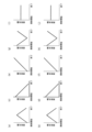
- FIG. 5 is a diagram schematically showing temporal changes in the irradiation light intensity of the first irradiation light and temporal changes in the irradiation light intensity of the second irradiation light.
- FIGS. 5(a), (c), (e), (g) and (i) are diagrams schematically showing temporal changes in the irradiation light intensity of the first irradiation light.
- 5(b), (d), (f), (h) and (j) are diagrams schematically showing temporal changes in the amount of irradiation light of the second irradiation light.
- the irradiation light amount of the first irradiation light may gradually increase as the irradiation time elapses, and then gradually decrease as the irradiation time elapses, as shown in FIG. 5(a). Further, the irradiation light amount of the first irradiation light may gradually decrease as the irradiation time elapses, as shown in FIG. 5(c). Further, the irradiation light amount of the first irradiation light may gradually increase as the irradiation time elapses, as shown in FIG. 5(e).
- the irradiation light amount of the first irradiation light may gradually decrease as the irradiation time elapses, and then gradually increase as the irradiation time elapses, as shown in FIG. 5(g). Further, the irradiation light amount of the first irradiation light may be constant from the start of irradiation to the end of irradiation, as shown in FIG. 5(i).
- the irradiation light amount of the second irradiation light may gradually increase as the irradiation time elapses and then gradually decrease as the irradiation time elapses, as shown in FIG. 5(b). Also, the irradiation light amount of the second irradiation light may gradually decrease as the irradiation time elapses, as shown in FIG. 5(d). Further, the irradiation light amount of the second irradiation light may gradually increase as the irradiation time elapses, as shown in FIG. 5(f). Moreover, as shown in FIG.
- the irradiation light amount of the second irradiation light may gradually decrease as the irradiation time elapses and then gradually increase as the irradiation time elapses. Further, the irradiation light amount of the second irradiation light may be constant from the start of irradiation to the end of irradiation, as shown in FIG. 5(j).
- the first irradiation modes shown in FIGS. 5(a), (c), (e), (g) and (i) and FIGS. ), (f), (h), and (j) can be used in appropriate combination with the irradiation modes of the second irradiation light.
- the irradiation mode of the first irradiation light shown in FIG. 5A and the irradiation mode of the second irradiation light shown in FIG. 5F may be used in combination.
- the irradiation mode of the first irradiation light shown in FIG. 5(g) and the irradiation mode of the second irradiation light shown in FIG. 5(f) may be used in combination.
- the irradiation form of the first irradiation light shown in FIG. It is preferable to use it in combination with the irradiation form of the second irradiation light.
- the ridges 5B formed by irradiation with light having a wavelength of 200 nm or less have a finer structure and a finer structure than an uneven shape formed on the surface of the surface protective layer 5 by mechanical processing such as embossing. It's becoming By forming such fine irregularities on the surface of the surface protective layer 5, it is possible to improve fingerprint resistance while maintaining the matte feel of the surface of the decorative sheet 1.
- the layer thickness of the surface protective layer 5 is preferably in the range of 2 ⁇ m or more and 20 ⁇ m or less. More preferably, the layer thickness of the surface protective layer 5 is in the range of 5 ⁇ m or more and 20 ⁇ m or less. More preferably, the layer thickness of the surface protective layer 5 is in the range of 8 ⁇ m or more and 15 ⁇ m or less. Most preferably, the layer thickness of the surface protective layer 5 is in the range of 10 ⁇ m or more and 12 ⁇ m or less. If the layer thickness of the surface protective layer 5 is less than 2 ⁇ m, the shaping by vacuum ultraviolet light cannot be deepened, and the glossiness cannot be reduced.
- the layer thickness of the surface protective layer 5 is such that the ratio of the layer thickness of the ridged portion 5B to the layer thickness of the core portion 5A (layer thickness of the ridged portion 5B/layer thickness of the core portion 5A) is 0.01 or more and 2 It is preferably set to 0.0 or less, and more preferably set to 0.1 or more and 1.0 or less.
- the pattern layer 3 and the surface protective layer 5 can be formed by various printing methods such as gravure printing, offset printing, screen printing, electrostatic printing, and inkjet printing.
- the surface protective layer 5 covers the entire surface of the raw fabric layer 2 on the surface side, it can be coated by various coating methods such as roll coating, knife coating, micro gravure coating, and die coating. can be formed. These printing methods or coating methods may be selected separately depending on the layers to be formed, or the same method may be selected for collective processing.
- the pattern layer 3 and the surface protective layer 5 may be synchronized from the viewpoint of design. In the case of synchronization, it is preferable to use the gravure printing method because it is necessary to collectively form the surface protective layer 5 after forming the pattern layer 3 .
- the gravure printing method is advantageous in terms of cost and is preferable because it can handle relatively high speeds.
- the alignment means that 50% or more, preferably 70% or more, and most preferably 90% or more of the portion where the surface protective layer 5 is formed overlaps with the pattern portion of the pattern layer 3 in plan view. do.
- the coating amount may be adjusted in the above-described printing method and coating method.
- the coating amount can be calculated from the mass difference between a base material (original fabric layer) with and without a surface protective layer formed in various printing methods and coating methods.
- the main material of the surface protective layer 5 is an ionizing radiation curable resin.
- the main material means that it contains 60 parts by mass or more, more preferably 70 parts by mass or more, and most preferably 80 parts by mass or more based on 100 parts by mass of the surface protective layer.
- the ionizing radiation curable resin constituting the surface protective layer 5 known ones such as various monomers and commercially available oligomers can be used.
- (meth)acrylic resin silicone resin, polyester resin , urethane-based resins, amide-based resins, and epoxy-based resins
- the ionizing radiation-curable resin may be either a water-based resin or a non-aqueous (organic solvent-based) resin.
- the main component of the ionizing radiation-curable resin forming the surface protective layer 5 is a trifunctional acrylate resin containing a repeating structure.
- trifunctional acrylate resins that can be used include trimethylolpropane triacrylate, glycerin triacrylate, isocyanurate triacrylate, and pentaerythritol triacrylate.
- trimethylolpropane triacrylate is used as the main component of the ionizing radiation curable resin constituting the surface protective layer 5, even if the integrated light intensity of the first irradiation light is low (for example, the integrated light intensity is 0 .1 mJ/cm 2 ), the curing reaction proceeds.
- trimethylolpropane triacrylate has a relatively high absorbance (absorbance coefficient) for light having a wavelength of 200 nm or less, which is the first irradiation light.
- the main component refers to 60 parts by mass or more, more preferably 70 parts by mass or more, and most preferably 80 parts by mass or more based on 100 parts by mass of the constituent resin component.
- a bifunctional acrylate resin is not preferable because the degree of cross-linking is insufficient and the scratch resistance is lowered. In the case of a tetrafunctional or higher acrylate resin, the degree of cross-linking becomes too high, which is not preferable because the workability is lowered.
- the ionizing radiation curable resin has a suitable viscosity range of 10 to 500 mPa ⁇ s and an optimum viscosity range of 100 to 200 mPa ⁇ s when gravure printing is used as the coating method. Therefore, it is preferable to use trimethylolpropane triacrylate or glycerin triacrylate as the trifunctional acrylate resin, because it is possible to keep the viscosity within a suitable or optimum viscosity range.
- a resin having a skeleton that causes hydrogen bonding or ⁇ - ⁇ stacking often has a high viscosity of 500 mPa ⁇ s or more, which is not preferable.
- an organic solvent or a low-viscosity bifunctional acrylate resin can be added to adjust the viscosity.
- organic solvents it is preferable not to use organic solvents.
- a bifunctional acrylate resin is not preferable because a large amount of the bifunctional acrylate resin decreases scratch resistance. Therefore, when a bifunctional acrylate resin is used by adding it to a trifunctional acrylate resin, the content of the bifunctional acrylate resin is in the range of 10% by mass or more and 30% by mass or less of the content (mass) of the trifunctional acrylate resin. is preferred, and a range of 15% by mass or more and 20% by mass or less is more preferable.
- the repeating structure of the main component of the ionizing radiation curable resin is any one of ethylene oxide (EO) structure, propylene oxide (PO) structure, and ⁇ -caprolactone (CL) structure. More preferably, the repeating structure is ethylene oxide or propylene oxide. Since the ethylene oxide structure, propylene oxide structure, and ⁇ -caprolactone structure have molecules that can rotate freely and have high flexibility, the surface hardened layer formed by light irradiation of 200 nm or less is subjected to buckling deformation for shaping. less stress required for Therefore, it is more preferable because the hardened surface layer (the surface layer of the surface protective layer) is easily formed with fine irregularities.
- EO ethylene oxide
- PO propylene oxide
- CL ⁇ -caprolactone
- the number of repetitions of the repeating structure in the main component of the ionizing radiation-curable resin is preferably 3 or more, more preferably 6 or more and 20 or less, and most preferably 9 or more and 15 or less. If the number of repetitions is 2 or less, the cross-linking density of the ionizing radiation curable resin constituting the surface protective layer 5 increases when the vacuum ultraviolet light (VUV light) is irradiated, so that the surface is not sufficiently shaped and the surface is protected. Layer 5 does not become low gloss. When the number of repetitions is more than 30, the crosslink density is lowered and the scratch resistance of the surface protective layer 5 is deteriorated.
- VUV light vacuum ultraviolet light
- the ionizing radiation curable resin having the repeating structure main component of the ionizing radiation curable resin
- the ratio of the number of carbon atoms containing only single bonds is hereinafter defined as "single bond carbon ratio".
- a formula for calculating the single bond carbon ratio can be expressed as the following formula (1).
- a resin having a single bond carbon ratio within the range of 0.725 or more and 0.955 or less is used.
- the single bond carbon content is more preferably in the range of 0.820 or more and 0.930 or less, and most preferably in the range of 0.860 or more and 0.920 or less. If the single-bond carbon ratio is less than 0.725, the ionizing radiation-curable resin constituting the surface protective layer 5 becomes too hard, so that the surface protective layer 5 does not have a sufficiently ridged shape, and the surface protective layer 5 does not have a low gloss.
- the single bond carbon ratio is greater than 0.955, the resin becomes too soft, and the scratch resistance of the surface protective layer 5 deteriorates. Moreover, if the single bond carbon ratio is within the range of 0.820 or more and 0.930 or less, the design and scratch resistance of the decorative sheet are further improved. Further, when the single bond carbon content is within the range of 0.860 or more and 0.920 or less, the design of the decorative sheet is further improved.
- the above single bond carbon ratio can be calculated by analyzing the molecular structure of the main component of the ionizing radiation curable resin and applying formula (1) to the molecular structure.
- NMR, MALDI-TOF-MS, IR, etc. can be used as methods for analyzing the main component of the ionizing radiation curable resin.
- the ionizing radiation curable resin may have a molecular weight distribution due to the difference in the number of repetitions of the repeating structure. If there is a molecular weight distribution, the main component is the molecular weight having the strongest peak in the mass spectrum of MALDI-TOF-MS.
- the ratio of carbon having only single bonds (so-called single-bond carbon) on the surface protective layer 5 can be measured using X-ray photoelectron spectroscopy (XPS) or X-ray absorption fine structure (XAFS).
- XPS X-ray photoelectron spectroscopy
- XAFS X-ray absorption fine structure
- a chemical modification method is used to replace the peak of another element, the peak area of C1s, the peak area of another element corresponding to the carbonyl group, and the other element for the alkyl moiety
- the ratio of the derived peak areas can be used to calculate the ratio of single-bonded carbons to double-bonded carbons.
- carboxyl groups trifluoroethanol (TFE), di-t-butylcarbodiimide (Di-t-BuC), and pyridine are used, and pyridine is used as a catalyst to add trifluoroethanol to carboxyl groups. method can be used.
- reagents TFE: 0.9 ml, Di-t-BuC: 0.3 ml, pyridine: 0.4 ml
- TFE 0.9 ml
- Di-t-BuC 0.3 ml
- pyridine 0.4 ml
- the content of carbon having a carbonyl group can be calculated from each peak area of C1s and F1s on the surface.
- the alkyl moiety is substituted with OsO4 by the gas phase method, and the content of carbon that was the alkyl moiety is calculated from the peak area derived from the 4f orbital of Os and the peak area of C1s. can.
- the ratio of single-bonded carbon can be calculated by comparing the content of carbon having a carboxyl group, the content of carbon that is the alkyl portion, or the content of other carbon.
- the quantitative determination of single-bonded carbon described above can be performed using, for example, the following equipment.
- the accuracy of quantification of single-bonded carbon can be improved by performing the following correction, peak separation, and the like.
- Measuring device JPS-9010MX (manufactured by JEOL Ltd.)
- X-ray source MgK ⁇ (10 kV)
- Peak position correction The peak due to sp3-derived CC bond is corrected to 285.5 eV.
- Peak separation can be performed using known methods such as the Lorentzian function and the Gaussian function. Those skilled in the art can easily understand that a function with a high fitting rate may be appropriately used when separating peaks.
- the surface protective layer 5 may contain particles.
- a uniform surface can be formed by adding particles of optimum particle size and optimum content.
- the particles for example, organic materials such as PE wax, PP wax, and resin beads, or inorganic materials such as silica, glass, alumina, titania, zirconia, calcium carbonate, and barium sulfate can be used.
- the average particle size of the particles is preferably 10 ⁇ m or less. It is more preferably 1 ⁇ m or more and 8 ⁇ m or less, still more preferably 2 ⁇ m or more and 6 ⁇ m or less, and most preferably 4 ⁇ m or more and 5 ⁇ m or less. If it is larger than 10 ⁇ m, the scratch resistance is lowered due to particle shedding, which is not preferable. If it is less than 1 ⁇ m, the effect of making the surface uniform is small, which is not preferable.
- the amount of the particles to be added is preferably 0.5 parts by mass or more and 10 parts by mass or less with respect to 100 parts by mass of the ionizing radiation-curable resin. More preferably, the amount of particles added is 2 to 8 parts by mass, more preferably 2 to 6 parts by mass, and most preferably 4 to 5 parts by mass.
- the surface protective layer 5 can form a uniform surface state by containing the particles in the above-mentioned amount, which is preferable.
- the "particle diameter (average particle diameter)" may be a value (average value) obtained by measuring the particle size distribution of the particles used, or the particle diameters of a plurality of particles obtained by observing the cross section of the obtained decorative material. may be a value obtained by actually measuring and averaging.
- the obtained particle size values are substantially the same.
- the average particle size of the particles added to the surface protective layer 5 may be the median size (D50) measured with a laser diffraction/scattering particle size distribution analyzer.
- the photoinitiator is not particularly limited, examples thereof include benzophenone-based, acetophenone-based, benzoin ether-based, and thioxanthone-based initiators. Functional additives such as antibacterial agents and antifungal agents may optionally be added to the surface protective layer 5 in order to impart required functions. Moreover, an ultraviolet absorber and a light stabilizer can be added to the surface protective layer 5 as necessary. It is common to add UV absorbers such as benzotriazole, benzoate, benzophenone, and triazine, and light stabilizers such as hindered amines in any combination.
- Such a decorative sheet 1 has a glossiness of 5.0 or less, even though it does not contain a glossiness adjusting agent (matting additive), and is a decorative sheet with extremely low glossiness.
- a glossiness adjusting agent such additive
- the content of the gloss modifier in the surface protective layer is high and the surface protective layer becomes cloudy. For this reason, there is a risk that the colors and patterns of the colored pattern layer will not be clearly expressed, or that the design of the decorative sheet will be deteriorated.
- the content of the gloss modifier in the surface protective layer is even higher, so that the surface can be smoothed without causing streaks, unevenness, etc.
- the decorative sheet 1 can provide a low-gloss decorative sheet with a glossiness of 5.0 or less while maintaining performance comparable to that of a decorative sheet having a glossiness of 20 or more.
- glossiness is a value measured at an incident angle of 60 degrees using a gloss meter conforming to JIS Z8741.
- the concealing layer 8 can basically be made of the same material as the pattern layer 3. However, since the concealing property is intended, for example, an opaque pigment, titanium oxide, iron oxide, or the like is used as the pigment. is preferred. Moreover, in order to improve hiding power, it is also possible to add metals such as gold, silver, copper and aluminum. In general, flaky aluminum is often added.
- a manufacturing example of the decorative sheet 1 will be described.
- a resin film is used as the original fabric layer 2, and the surface protective layer 5 is formed on the upper surface of the original fabric layer 2 by printing.
- the surface protective layer 5 is formed by irradiating the surface of the applied ionizing radiation curable resin with light having a wavelength of 200 nm or less (first irradiation light) to cure the surface of the ionizing radiation curable resin, and is seated by internal stress. Shaped by bending. Subsequently, in order to further cure the ionizing radiation curable resin, ionizing radiation or UV light having a longer wavelength than light having a wavelength of 200 nm or less, which is the first irradiation light, is applied.
- the decorative sheet 1 including the surface protective layer 5 having the core portion 5A and the ridged portion 5B protruding from one surface (upper surface) of the core portion 5A is formed.
- the decorative sheet 1 according to this embodiment includes a surface protective layer 5 having an uneven surface.
- the luster (glossiness) of the surface protective layer can be adjusted even if the surface protective layer does not contain a glossiness adjusting agent (matting additive). Since the luster modifier reduces the oil repellency of the layer formed of the resin material, fingerprints tend to stick to it. Since the surface protective layer 5 according to the present embodiment does not contain a luster adjusting agent, it does not absorb oil and has relatively improved oil repellency. Therefore, fingerprints are less likely to adhere to the decorative sheet 1 having the surface protective layer 5 in various situations during site construction, furniture assembly, and residents' daily lives.
- the oil repellency of the surface protective layer 5 is improved, and it is possible to suppress oil stains and adsorption of contaminants on the surface of the decorative sheet 1.
- the structure of the surface protective layer 5 that does not contain the glossiness adjusting agent when the surface of the decorative sheet 1 is scratched, the particles of the glossiness adjusting agent do not come off, and the glossiness of the surface of the decorative sheet 1 changes and scratches occur. It is possible to make it harder.
- the surface protective layer 5 is formed of a single layer in this embodiment, it is not limited to such a structure.
- a structure in which the surface protective layer 5 is multi-layered may be used. That is, the surface protective layer 5 may be formed by laminating a plurality of layers of the same ionizing radiation curable resin or laminating a plurality of layers of different ionizing radiation curable resins to form an uneven shape on the surface.
- the outermost layer of the surface protective layer 5 is made of an ionizing radiation-curable resin as a main material, and the ionizing radiation-curable resin has a repeating structure as a main component.
- the repeating structure is one of the structures of ethylene oxide, propylene oxide, and ⁇ -caprolactone, and the single bond carbon content is 0.725 or more and 0.955 or less.
- the layer located on the raw fabric layer 2 side of the surface protective layer 5 (that is, the layer located under the outermost layer of the surface protective layer 5) is not particularly limited.
- Example 1 A 55 ⁇ m-thick olefin film (manufactured by Riken Technos Co., Ltd.) was used as a base layer, one side of the base layer was subjected to corona treatment, and the following surface protective layer coating liquid was applied to one side.
- the layer thickness of the coating liquid for the surface protective layer was set to 5 ⁇ m.
- the surface of the surface protective layer coating liquid was irradiated with a Xe excimer laser with a wavelength of 172 nm to shape the surface.
- the surface protective layer 5 was formed by irradiating ionizing radiation to cure the surface protective layer coating liquid, and the decorative sheet of Example 1 having a total thickness of 60 ⁇ m was obtained.
- the surface protective layer coating liquid was prepared by blending the following particles with the following ionizing radiation curable resin.
- ⁇ Ionizing radiation curable resin Type Trimethylolpropane EO modified triacrylate (EO 6 moles added)
- Particle size 5 ⁇ m
- Compounding 0.5 parts by mass
- Example 2 A decorative sheet of Example 2 was obtained in the same manner as in Example 1, except that the ionizing radiation-curable resin of Example 1 was replaced with the following.
- ⁇ Ionizing radiation curable resin Type Trimethylolpropane EO-modified triacrylate (EO 15 moles added)
- Example 3 A decorative sheet of Example 3 was obtained in the same manner as in Example 1, except that the ionizing radiation-curable resin of Example 1 was replaced with the following.
- ⁇ Ionizing radiation curable resin Type trimethylolpropane EO-modified triacrylate (3 moles of EO added)
- Example 4 A decorative sheet of Example 4 was obtained in the same manner as in Example 1, except that the ionizing radiation-curable resin of Example 1 was replaced with the following.
- ⁇ Ionizing radiation curable resin Type trimethylolpropane PO-modified triacrylate (6 moles of PO added)
- Example 5 A decorative sheet of Example 5 was obtained in the same manner as in Example 1, except that the ionizing radiation-curable resin of Example 1 was replaced with the following.
- ⁇ Ionizing radiation curable resin Type caprolactone-modified tris(2-acryloxyethyl) isocyanurate (3 mol of caprolactone (CL) added)
- Example 6> A decorative sheet of Example 6 having a total thickness of 56 ⁇ m was obtained in the same manner as in Example 1, except that the layer thickness of the surface protective layer coating liquid of Example 1 was changed to 1 ⁇ m.
- Example 7> A decorative sheet of Example 7 having a total thickness of 57 ⁇ m was obtained in the same manner as in Example 1, except that the layer thickness of the surface protective layer coating liquid of Example 1 was changed to 2 ⁇ m.
- Example 8> A decorative sheet of Example 8 having a total thickness of 75 ⁇ m was obtained in the same manner as in Example 1 except that the layer thickness of the surface protective layer coating liquid of Example 1 was changed to 20 ⁇ m.
- Example 9> A decorative sheet of Example 9 having a total thickness of 80 ⁇ m was obtained in the same manner as in Example 1, except that the layer thickness of the surface protective layer coating liquid of Example 1 was changed to 25 ⁇ m.
- Example 10> A decorative sheet of Example 10 was obtained in the same manner as in Example 9 except that the particles of Example 9 were not blended.
- Example 11> A decorative sheet of Example 11 was obtained in the same manner as in Example 3, except that the particles of Example 3 were not blended.
- Example 12 A decorative sheet of Example 12 was obtained in the same manner as in Example 1 except that the particles of Example 1 were replaced with the following.
- Example 13 A decorative sheet of Example 13 was obtained in the same manner as in Example 1, except that the particles of Example 1 were replaced with the following.
- Example 14> A decorative sheet of Example 14 was obtained in the same manner as in Example 1 except that the amount of the particles of Example 1 was changed to 10 parts by mass.
- Example 15> A decorative sheet of Example 15 was obtained in the same manner as in Example 1, except that the amount of the particles of Example 1 was changed to 11 parts by mass.
- Example 16> A decorative sheet of Example 16 having a total thickness of 56 ⁇ m was obtained in the same manner as in Example 1, except that the surface protective layer coating liquid of Example 1 had a layer thickness of 1 ⁇ m and no particles were used.
- Example 17 A decorative sheet of Example 17 was obtained in the same manner as in Example 1, except that the ionizing radiation-curable resin of Example 1 was replaced with the following.
- ⁇ Ionizing radiation curable resin Type Trimethylolpropane EO-modified triacrylate (20 moles of EO added)
- Example 18 A decorative sheet of Example 18 was obtained in the same manner as in Example 1, except that the ionizing radiation-curable resin of Example 1 was replaced with the following.
- ⁇ Ionizing radiation curable resin Type Trimethylolpropane EO-modified triacrylate (30 moles of EO added)
- ⁇ Comparative Example 1> A decorative sheet of Comparative Example 1 was obtained in the same manner as in Example 1, except that the excimer laser irradiation of Example 1 was omitted and the amount of the particles was changed to 15 parts by mass.
- ⁇ Comparative Example 2> A decorative sheet of Comparative Example 2 was obtained in the same manner as in Example 1, except that the ionizing radiation-curable resin of Example 1 was replaced with the following.
- ⁇ Ionizing radiation curable resin Type Ethylene glycol diacrylate (addition of 9 moles of EO)
- Comparative Example 3 A decorative sheet of Comparative Example 3 was obtained in the same manner as in Example 1, except that the ionizing radiation-curable resin of Example 1 was replaced with the following.
- ⁇ Ionizing radiation curable resin Type Pentaerythritol tetraacrylate (35 moles of EO added)
- Single bond carbon ratio 0.96
- Comparative Example 4 A decorative sheet of Comparative Example 4 was obtained in the same manner as in Example 1, except that the ionizing radiation-curable resin of Example 1 was replaced with the following.
- ⁇ Ionizing radiation curable resin Type Trimethylolpropane triacrylate Product name: NK Ester A-TMPT (manufactured by Shin-Nakamura Chemical Co., Ltd.) Single bond carbon ratio: 0.4
- ⁇ Surface condition> As for the surface condition, the uniformity of the surface was evaluated by visual observation. The evaluation criteria were as follows. ⁇ : Uniform surface condition ⁇ : Partially uneven ⁇ : Overall uneven surface condition
- Glossiness was measured at 60 degrees using Rhopoint IQ (manufactured by Konica Minolta). In Tables 1 to 3, this 60° glossiness is indicated as "60° gloss value”. Incidentally, if the glossiness is 15 or less, it is generally recognized as low gloss.
- ⁇ Fingerprint resistance evaluation of wiping property>
- a fingerprint wiping off evaluation was performed.
- the 60-degree glossiness of the surface of each decorative sheet was measured and defined as [initial glossiness].
- the anti-fingerprint evaluation liquid adhering to the surface of the decorative sheet was wiped off.
- the 60-degree glossiness of the portion from which the anti-fingerprint evaluation liquid was wiped off was measured and referred to as [glossiness after wiping].
- a higher fatty acid was used as the anti-fingerprint evaluation liquid.
- the fingerprint wiping rate was calculated as follows.
- Fingerprint wiping rate (%) (glossiness after wiping/initial glossiness) x 100
- the evaluation criteria were as follows. ⁇ : 70% or more and less than 250% ⁇ : 50% or more and less than 70%, or 250% or more and less than 300% ⁇ : Less than 50%, or 300% or more
- ⁇ Stain resistance> As a contamination resistance evaluation, a line with a width of 10 mm is drawn with blue ink, black quick-drying ink and red crayon by the contamination A test specified in Japanese Agricultural Standards (JAS), left for 4 hours, ethanol was soaked in a cloth and wiped off the blue ink, black quick-drying ink and red crayon lines to evaluate the resistance to staining by the ink.
- the evaluation criteria were as follows. ⁇ : The lines of each color could be easily wiped off. ⁇ : Some of the lines of each color could be wiped off, but some stains remained. ⁇ : The lines of each color could not be wiped off.
- ⁇ Scratch resistance test steel wool rubbing test> After the obtained decorative sheet was attached to the wooden substrate B using a urethane-based adhesive, a steel wool rubbing test was carried out as a scratch resistance evaluation. A load of 100 g was applied to steel wool, and the sheet was rubbed back and forth 20 times. The evaluation criteria were as follows. ⁇ : No scratches or change in gloss on the surface ⁇ : Slight scratches or change in gloss on the surface ⁇ : Significant scratches or change in gloss on the surface
- ⁇ Bendability test> The resulting decorative sheet is attached to the woody substrate B using a urethane-based adhesive so that the raw fabric layer side surface (that is, the back side of the decorative sheet) faces the woody substrate B side, and then the decorative sheet is applied.
- a V-shaped groove is formed up to the boundary where the wooden substrate B and the decorative sheet 1 are stuck together so as not to damage the sheet.
- the wooden substrate B is bent up to 90 degrees along the V-shaped groove so that the surface of the decorative sheet on the surface protection layer side (that is, the surface of the decorative sheet) is folded into a mountain, and the surface of the decorative sheet is bent.
- An optical microscope was used to observe whether whitening or cracks occurred in the bent portion, and the state of bending workability was evaluated. The evaluation criteria were as follows. ⁇ : Whitening and cracks are not seen ⁇ : Whitening is seen in part ⁇ : Whitening is seen on the entire surface or cracks are seen in part
- the decorative sheets of Examples 1 to 18 provide a decorative sheet having both fingerprint resistance, scratch resistance, stain resistance, and bending workability while maintaining low gloss. be able to.
- the layer thickness of the surface protective layer and the particle size and addition amount of the particles to be blended can be optimized to further improve performance.
Landscapes
- Laminated Bodies (AREA)
Abstract
La présente invention concerne : une feuille décorative à faible brillance qui présente d'excellentes propriétés de conception, tout en ayant une résistance aux empreintes digitales, une durabilité élevée (en particulier une résistance aux rayures et une résistance à la contamination) et une aptitude au traitement élevée ; et un procédé de production de cette feuille décorative. Une feuille décorative (1) selon un mode de réalisation de la présente invention comprend une couche maître (2) et une couche de protection de surface (5) qui est disposée sur une surface de la couche maître (2). La surface de la couche de protection de surface (5) est pourvue de parties d'arête qui font saillie sous la forme de crêtes, formant ainsi un motif en relief. Le motif en relief de la couche de protection de surface (5) a un rapport RSm/Ra dans la plage allant de 10 à 300 (inclus). Le matériau principal de la couche de protection de surface (5) est une résine durcissable par rayonnement ionisant. La principale composante de la résine durcissable par rayonnement ionisant est une résine acrylique trifonctionnelle qui comprend une structure répétitive. La structure répétitive est l'une quelconque d'une structure d'oxyde d'éthylène, d'une structure d'oxyde de propylène et d'une structure d'ε-caprolactone. Le rapport carbone lié simple dans la composante principale de la résine durcissable par rayonnement ionisant dans la plage allant de 0,725 à 0,955 (inclus).
Applications Claiming Priority (2)
| Application Number | Priority Date | Filing Date | Title |
|---|---|---|---|
| JP2021-198489 | 2021-12-07 | ||
| JP2021198489 | 2021-12-07 |
Publications (1)
| Publication Number | Publication Date |
|---|---|
| WO2023106340A1 true WO2023106340A1 (fr) | 2023-06-15 |
Family
ID=86730581
Family Applications (1)
| Application Number | Title | Priority Date | Filing Date |
|---|---|---|---|
| PCT/JP2022/045138 WO2023106340A1 (fr) | 2021-12-07 | 2022-12-07 | Feuille décorative et procédé de production d'une feuille décorative |
Country Status (1)
| Country | Link |
|---|---|
| WO (1) | WO2023106340A1 (fr) |
Cited By (1)
| Publication number | Priority date | Publication date | Assignee | Title |
|---|---|---|---|---|
| WO2024010066A1 (fr) * | 2022-07-06 | 2024-01-11 | Toppanホールディングス株式会社 | Feuille décorative et procédé de fabrication de feuille décorative |
Citations (16)
| Publication number | Priority date | Publication date | Assignee | Title |
|---|---|---|---|---|
| US6663952B1 (en) * | 1998-10-09 | 2003-12-16 | Wkp Wurttembergische Kunststoffplatten-Werke Gmbh & Co. Kg | Stratified material and a method for producing the same |
| US20150354132A1 (en) * | 2013-01-17 | 2015-12-10 | Armstrong World Industries, Inc | Curing methods and products produced therefrom |
| JP2016099671A (ja) * | 2014-11-18 | 2016-05-30 | 大日本印刷株式会社 | スライドパッド用シート、突起部付きスライドパッド用シート、及びこれらを用いたスライドパッド、並びに突起部付きスライドパッド用シートの製造方法 |
| US20160152833A1 (en) * | 2013-06-14 | 2016-06-02 | Covestro Deutschland Ag | Direction-independently impact-resistant 3-d molded parts |
| JP2017171794A (ja) * | 2016-03-24 | 2017-09-28 | 東洋インキScホールディングス株式会社 | 紫外線硬化型コート剤組成物および積層体 |
| WO2019244791A1 (fr) * | 2018-06-21 | 2019-12-26 | 三菱ケミカル株式会社 | Film de résine acrylique mat |
| US20200024439A1 (en) * | 2017-05-22 | 2020-01-23 | Lg Hausys, Ltd. | Low-gloss cured product having excellent stain resistance, and manufacturing method therefor |
| KR20200031282A (ko) * | 2018-09-14 | 2020-03-24 | (주)엘지하우시스 | 촉감이 우수한 저광택의 데코 시트 |
| KR20200059905A (ko) * | 2018-11-22 | 2020-05-29 | (주)엘지하우시스 | 내오염성 및 심미적 효과가 우수한 장식재 및 이의 제조방법 |
| JP2020111715A (ja) * | 2019-01-17 | 2020-07-27 | 三菱ケミカル株式会社 | 硬化物 |
| JP2021053996A (ja) * | 2019-09-30 | 2021-04-08 | 大日本印刷株式会社 | 化粧シート |
| JP2021115701A (ja) * | 2020-01-22 | 2021-08-10 | 凸版印刷株式会社 | 化粧シート、化粧板及び化粧シートの製造方法 |
| JP2021137990A (ja) * | 2020-03-03 | 2021-09-16 | 凸版印刷株式会社 | 化粧シート、化粧板及び化粧シートの製造方法 |
| WO2021201105A1 (fr) * | 2020-03-31 | 2021-10-07 | 大日本印刷株式会社 | Article mat et procédé de production d'un article mat |
| WO2022145137A1 (fr) * | 2020-12-28 | 2022-07-07 | 凸版印刷株式会社 | Feuille décorative et procédé de fabrication d'une feuille décorative |
| WO2022239270A1 (fr) * | 2021-05-12 | 2022-11-17 | 凸版印刷株式会社 | Feuille décorative et procédé de production d'une feuille décorative |
-
2022
- 2022-12-07 WO PCT/JP2022/045138 patent/WO2023106340A1/fr active Application Filing
Patent Citations (16)
| Publication number | Priority date | Publication date | Assignee | Title |
|---|---|---|---|---|
| US6663952B1 (en) * | 1998-10-09 | 2003-12-16 | Wkp Wurttembergische Kunststoffplatten-Werke Gmbh & Co. Kg | Stratified material and a method for producing the same |
| US20150354132A1 (en) * | 2013-01-17 | 2015-12-10 | Armstrong World Industries, Inc | Curing methods and products produced therefrom |
| US20160152833A1 (en) * | 2013-06-14 | 2016-06-02 | Covestro Deutschland Ag | Direction-independently impact-resistant 3-d molded parts |
| JP2016099671A (ja) * | 2014-11-18 | 2016-05-30 | 大日本印刷株式会社 | スライドパッド用シート、突起部付きスライドパッド用シート、及びこれらを用いたスライドパッド、並びに突起部付きスライドパッド用シートの製造方法 |
| JP2017171794A (ja) * | 2016-03-24 | 2017-09-28 | 東洋インキScホールディングス株式会社 | 紫外線硬化型コート剤組成物および積層体 |
| US20200024439A1 (en) * | 2017-05-22 | 2020-01-23 | Lg Hausys, Ltd. | Low-gloss cured product having excellent stain resistance, and manufacturing method therefor |
| WO2019244791A1 (fr) * | 2018-06-21 | 2019-12-26 | 三菱ケミカル株式会社 | Film de résine acrylique mat |
| KR20200031282A (ko) * | 2018-09-14 | 2020-03-24 | (주)엘지하우시스 | 촉감이 우수한 저광택의 데코 시트 |
| KR20200059905A (ko) * | 2018-11-22 | 2020-05-29 | (주)엘지하우시스 | 내오염성 및 심미적 효과가 우수한 장식재 및 이의 제조방법 |
| JP2020111715A (ja) * | 2019-01-17 | 2020-07-27 | 三菱ケミカル株式会社 | 硬化物 |
| JP2021053996A (ja) * | 2019-09-30 | 2021-04-08 | 大日本印刷株式会社 | 化粧シート |
| JP2021115701A (ja) * | 2020-01-22 | 2021-08-10 | 凸版印刷株式会社 | 化粧シート、化粧板及び化粧シートの製造方法 |
| JP2021137990A (ja) * | 2020-03-03 | 2021-09-16 | 凸版印刷株式会社 | 化粧シート、化粧板及び化粧シートの製造方法 |
| WO2021201105A1 (fr) * | 2020-03-31 | 2021-10-07 | 大日本印刷株式会社 | Article mat et procédé de production d'un article mat |
| WO2022145137A1 (fr) * | 2020-12-28 | 2022-07-07 | 凸版印刷株式会社 | Feuille décorative et procédé de fabrication d'une feuille décorative |
| WO2022239270A1 (fr) * | 2021-05-12 | 2022-11-17 | 凸版印刷株式会社 | Feuille décorative et procédé de production d'une feuille décorative |
Cited By (1)
| Publication number | Priority date | Publication date | Assignee | Title |
|---|---|---|---|---|
| WO2024010066A1 (fr) * | 2022-07-06 | 2024-01-11 | Toppanホールディングス株式会社 | Feuille décorative et procédé de fabrication de feuille décorative |
Similar Documents
| Publication | Publication Date | Title |
|---|---|---|
| WO2022145137A1 (fr) | Feuille décorative et procédé de fabrication d'une feuille décorative | |
| WO2022239270A1 (fr) | Feuille décorative et procédé de production d'une feuille décorative | |
| JP4658749B2 (ja) | 耐衝撃性及び耐スクラッチ性に優れた床材用化粧シート | |
| WO2008044398A1 (fr) | film pour revêtement dur, son procédé de fabrication et film antireflet | |
| JP5429129B2 (ja) | 耐衝撃性及び耐スクラッチ性に優れた床材用化粧シート | |
| WO2023106340A1 (fr) | Feuille décorative et procédé de production d'une feuille décorative | |
| JP5691150B2 (ja) | 床材用化粧シート及び床用化粧材 | |
| KR20220113746A (ko) | 화장 시트, 화장판 및 화장 시트의 제조 방법 | |
| JP2011067975A (ja) | 化粧シート及び化粧材 | |
| JP2009235791A (ja) | 床材用化粧シート及び床用化粧材 | |
| WO2023095914A1 (fr) | Feuille décorative et procédé de production d'une feuille décorative | |
| WO2023136304A1 (fr) | Feuille décorative et procédé de production d'une feuille décorative | |
| WO2023282295A1 (fr) | Feuille décorative et procédé de production d'une feuille décorative | |
| WO2023191052A1 (fr) | Feuille décorative et procédé de fabrication d'une feuille décorative | |
| JP6963273B2 (ja) | 化粧シート及び化粧シートの製造方法 | |
| WO2023171805A1 (fr) | Feuille décorative et procédé de production de feuille décorative | |
| WO2023224115A1 (fr) | Feuille décorative et procédé de fabrication de la feuille décorative | |
| WO2024019096A1 (fr) | Feuille décorative et procédé de fabrication de feuille décorative | |
| US20240173937A1 (en) | Decorative sheet and method for producing decorative sheet | |
| WO2023238893A1 (fr) | Feuille décorative et procédé de fabrication de la feuille décorative | |
| WO2023249080A1 (fr) | Feuille décorative | |
| WO2023249082A1 (fr) | Feuille décorative | |
| WO2023249081A1 (fr) | Feuille décorative | |
| WO2024010066A1 (fr) | Feuille décorative et procédé de fabrication de feuille décorative | |
| JP6736844B2 (ja) | 化粧シート及び化粧板 |
Legal Events
| Date | Code | Title | Description |
|---|---|---|---|
| 121 | Ep: the epo has been informed by wipo that ep was designated in this application |
Ref document number: 22904268 Country of ref document: EP Kind code of ref document: A1 |
|
| WWE | Wipo information: entry into national phase |
Ref document number: 2023566343 Country of ref document: JP |