WO2023106295A1 - 血圧測定装置及び血圧測定システム - Google Patents
血圧測定装置及び血圧測定システム Download PDFInfo
- Publication number
- WO2023106295A1 WO2023106295A1 PCT/JP2022/044935 JP2022044935W WO2023106295A1 WO 2023106295 A1 WO2023106295 A1 WO 2023106295A1 JP 2022044935 W JP2022044935 W JP 2022044935W WO 2023106295 A1 WO2023106295 A1 WO 2023106295A1
- Authority
- WO
- WIPO (PCT)
- Prior art keywords
- blood pressure
- value
- pressure value
- unit
- measured
- Prior art date
- Legal status (The legal status is an assumption and is not a legal conclusion. Google has not performed a legal analysis and makes no representation as to the accuracy of the status listed.)
- Ceased
Links
Images




Classifications
-
- A—HUMAN NECESSITIES
- A61—MEDICAL OR VETERINARY SCIENCE; HYGIENE
- A61B—DIAGNOSIS; SURGERY; IDENTIFICATION
- A61B5/00—Measuring for diagnostic purposes; Identification of persons
- A61B5/02—Detecting, measuring or recording for evaluating the cardiovascular system, e.g. pulse, heart rate, blood pressure or blood flow
- A61B5/021—Measuring pressure in heart or blood vessels
- A61B5/022—Measuring pressure in heart or blood vessels by applying pressure to close blood vessels, e.g. against the skin; Ophthalmodynamometers
- A61B5/02208—Measuring pressure in heart or blood vessels by applying pressure to close blood vessels, e.g. against the skin; Ophthalmodynamometers using the Korotkoff method
-
- A—HUMAN NECESSITIES
- A61—MEDICAL OR VETERINARY SCIENCE; HYGIENE
- A61B—DIAGNOSIS; SURGERY; IDENTIFICATION
- A61B5/00—Measuring for diagnostic purposes; Identification of persons
- A61B5/72—Signal processing specially adapted for physiological signals or for diagnostic purposes
- A61B5/7235—Details of waveform analysis
- A61B5/7246—Details of waveform analysis using correlation, e.g. template matching or determination of similarity
-
- A—HUMAN NECESSITIES
- A61—MEDICAL OR VETERINARY SCIENCE; HYGIENE
- A61B—DIAGNOSIS; SURGERY; IDENTIFICATION
- A61B5/00—Measuring for diagnostic purposes; Identification of persons
- A61B5/02—Detecting, measuring or recording for evaluating the cardiovascular system, e.g. pulse, heart rate, blood pressure or blood flow
- A61B5/0205—Simultaneously evaluating both cardiovascular conditions and different types of body conditions, e.g. heart and respiratory condition
-
- A—HUMAN NECESSITIES
- A61—MEDICAL OR VETERINARY SCIENCE; HYGIENE
- A61B—DIAGNOSIS; SURGERY; IDENTIFICATION
- A61B5/00—Measuring for diagnostic purposes; Identification of persons
- A61B5/02—Detecting, measuring or recording for evaluating the cardiovascular system, e.g. pulse, heart rate, blood pressure or blood flow
- A61B5/021—Measuring pressure in heart or blood vessels
- A61B5/02108—Measuring pressure in heart or blood vessels from analysis of pulse wave characteristics
- A61B5/02125—Measuring pressure in heart or blood vessels from analysis of pulse wave characteristics of pulse wave propagation time
-
- A—HUMAN NECESSITIES
- A61—MEDICAL OR VETERINARY SCIENCE; HYGIENE
- A61B—DIAGNOSIS; SURGERY; IDENTIFICATION
- A61B5/00—Measuring for diagnostic purposes; Identification of persons
- A61B5/02—Detecting, measuring or recording for evaluating the cardiovascular system, e.g. pulse, heart rate, blood pressure or blood flow
- A61B5/021—Measuring pressure in heart or blood vessels
- A61B5/022—Measuring pressure in heart or blood vessels by applying pressure to close blood vessels, e.g. against the skin; Ophthalmodynamometers
- A61B5/02225—Measuring pressure in heart or blood vessels by applying pressure to close blood vessels, e.g. against the skin; Ophthalmodynamometers using the oscillometric method
-
- A—HUMAN NECESSITIES
- A61—MEDICAL OR VETERINARY SCIENCE; HYGIENE
- A61B—DIAGNOSIS; SURGERY; IDENTIFICATION
- A61B5/00—Measuring for diagnostic purposes; Identification of persons
- A61B5/02—Detecting, measuring or recording for evaluating the cardiovascular system, e.g. pulse, heart rate, blood pressure or blood flow
- A61B5/024—Measuring pulse rate or heart rate
- A61B5/0245—Measuring pulse rate or heart rate by using sensing means generating electric signals, i.e. ECG signals
- A61B5/025—Measuring pulse rate or heart rate by using sensing means generating electric signals, i.e. ECG signals within occluders, e.g. responsive to Korotkoff sounds
-
- A—HUMAN NECESSITIES
- A61—MEDICAL OR VETERINARY SCIENCE; HYGIENE
- A61B—DIAGNOSIS; SURGERY; IDENTIFICATION
- A61B5/00—Measuring for diagnostic purposes; Identification of persons
- A61B5/24—Detecting, measuring or recording bioelectric or biomagnetic signals of the body or parts thereof
- A61B5/25—Bioelectric electrodes therefor
- A61B5/279—Bioelectric electrodes therefor specially adapted for particular uses
- A61B5/28—Bioelectric electrodes therefor specially adapted for particular uses for electrocardiography [ECG]
- A61B5/282—Holders for multiple electrodes
-
- A—HUMAN NECESSITIES
- A61—MEDICAL OR VETERINARY SCIENCE; HYGIENE
- A61B—DIAGNOSIS; SURGERY; IDENTIFICATION
- A61B5/00—Measuring for diagnostic purposes; Identification of persons
- A61B5/68—Arrangements of detecting, measuring or recording means, e.g. sensors, in relation to patient
- A61B5/6801—Arrangements of detecting, measuring or recording means, e.g. sensors, in relation to patient specially adapted to be attached to or worn on the body surface
- A61B5/6813—Specially adapted to be attached to a specific body part
- A61B5/6824—Arm or wrist
-
- A—HUMAN NECESSITIES
- A61—MEDICAL OR VETERINARY SCIENCE; HYGIENE
- A61B—DIAGNOSIS; SURGERY; IDENTIFICATION
- A61B5/00—Measuring for diagnostic purposes; Identification of persons
- A61B5/68—Arrangements of detecting, measuring or recording means, e.g. sensors, in relation to patient
- A61B5/6801—Arrangements of detecting, measuring or recording means, e.g. sensors, in relation to patient specially adapted to be attached to or worn on the body surface
- A61B5/683—Means for maintaining contact with the body
- A61B5/6831—Straps, bands or harnesses
-
- A—HUMAN NECESSITIES
- A61—MEDICAL OR VETERINARY SCIENCE; HYGIENE
- A61B—DIAGNOSIS; SURGERY; IDENTIFICATION
- A61B5/00—Measuring for diagnostic purposes; Identification of persons
- A61B5/74—Details of notification to user or communication with user or patient; User input means
- A61B5/742—Details of notification to user or communication with user or patient; User input means using visual displays
-
- A—HUMAN NECESSITIES
- A61—MEDICAL OR VETERINARY SCIENCE; HYGIENE
- A61B—DIAGNOSIS; SURGERY; IDENTIFICATION
- A61B2560/00—Constructional details of operational features of apparatus; Accessories for medical measuring apparatus
- A61B2560/02—Operational features
- A61B2560/0223—Operational features of calibration, e.g. protocols for calibrating sensors
- A61B2560/0228—Operational features of calibration, e.g. protocols for calibrating sensors using calibration standards
-
- A—HUMAN NECESSITIES
- A61—MEDICAL OR VETERINARY SCIENCE; HYGIENE
- A61B—DIAGNOSIS; SURGERY; IDENTIFICATION
- A61B2560/00—Constructional details of operational features of apparatus; Accessories for medical measuring apparatus
- A61B2560/02—Operational features
- A61B2560/0223—Operational features of calibration, e.g. protocols for calibrating sensors
- A61B2560/0238—Means for recording calibration data
-
- A—HUMAN NECESSITIES
- A61—MEDICAL OR VETERINARY SCIENCE; HYGIENE
- A61B—DIAGNOSIS; SURGERY; IDENTIFICATION
- A61B2560/00—Constructional details of operational features of apparatus; Accessories for medical measuring apparatus
- A61B2560/04—Constructional details of apparatus
- A61B2560/0462—Apparatus with built-in sensors
- A61B2560/0468—Built-in electrodes
-
- A—HUMAN NECESSITIES
- A61—MEDICAL OR VETERINARY SCIENCE; HYGIENE
- A61B—DIAGNOSIS; SURGERY; IDENTIFICATION
- A61B2562/00—Details of sensors; Constructional details of sensor housings or probes; Accessories for sensors
- A61B2562/02—Details of sensors specially adapted for in-vivo measurements
- A61B2562/0247—Pressure sensors
-
- A—HUMAN NECESSITIES
- A61—MEDICAL OR VETERINARY SCIENCE; HYGIENE
- A61B—DIAGNOSIS; SURGERY; IDENTIFICATION
- A61B2562/00—Details of sensors; Constructional details of sensor housings or probes; Accessories for sensors
- A61B2562/04—Arrangements of multiple sensors of the same type
- A61B2562/043—Arrangements of multiple sensors of the same type in a linear array
-
- A—HUMAN NECESSITIES
- A61—MEDICAL OR VETERINARY SCIENCE; HYGIENE
- A61B—DIAGNOSIS; SURGERY; IDENTIFICATION
- A61B5/00—Measuring for diagnostic purposes; Identification of persons
- A61B5/02—Detecting, measuring or recording for evaluating the cardiovascular system, e.g. pulse, heart rate, blood pressure or blood flow
- A61B5/021—Measuring pressure in heart or blood vessels
- A61B5/02141—Details of apparatus construction, e.g. pump units or housings therefor, cuff pressurising systems, arrangements of fluid conduits or circuits
-
- A—HUMAN NECESSITIES
- A61—MEDICAL OR VETERINARY SCIENCE; HYGIENE
- A61B—DIAGNOSIS; SURGERY; IDENTIFICATION
- A61B5/00—Measuring for diagnostic purposes; Identification of persons
- A61B5/02—Detecting, measuring or recording for evaluating the cardiovascular system, e.g. pulse, heart rate, blood pressure or blood flow
- A61B5/024—Measuring pulse rate or heart rate
- A61B5/0245—Measuring pulse rate or heart rate by using sensing means generating electric signals, i.e. ECG signals
Definitions
- the present invention relates to blood pressure measurement devices and blood pressure measurement systems.
- Patent Document 1 electrodes as an ECG (ElectroCardioGraphic) sensor and a pulse wave sensor such as a PPG (PhotoPlethysmoGraphic) sensor are provided on a belt portion wrapped around a user's site to be measured.
- a blood pressure measurement device is disclosed that measures blood pressure by calculating PTT based on the time difference from waveform feature points of a signal.
- the electrodes and the pulse wave sensor can be attached to the user by wrapping the belt portion around the user. Therefore, according to the technique described in Patent Document 1, a blood pressure measurement device is provided that is easy to wear on the user and can greatly reduce the burden on the user when performing non-invasive continuous blood pressure measurement on a daily basis. can do.
- Patent Literature 1 it is determined whether or not the conditions for recommending measurement of the user's blood pressure for calibration are satisfied, and if the conditions are satisfied, the information instructing the blood pressure measurement is output. is described.
- the present invention optimizes the frequency of calibrating the blood pressure value calculation algorithm according to the user when estimating the blood pressure of the human body using the feature value related to blood pressure value estimation.
- the purpose is to provide possible technology.
- a feature quantity acquisition unit that acquires one or more feature quantities related to estimation of a blood pressure value of a human body
- a blood pressure value calculation unit that calculates an estimated blood pressure value based on the feature quantity
- a measured blood pressure value acquisition unit that acquires a measured blood pressure value that is measured by a method different from the calculation by the blood pressure value calculation unit
- Calibration determination for determining whether or not the feature amount acquired by the feature amount acquisition unit deviates from a predetermined reference value, and determining to acquire the measured blood pressure value when it is determined that the feature amount has deviated.
- the blood pressure measuring device is characterized by:
- the feature values here include waveform-related values such as the height at an inflection point, the slope between inflection points, and the area of a predetermined portion of the waveform obtained from an electrocardiogram (ECG) or a pulse waveform.
- ECG electrocardiogram
- PTT pulse arrival time
- other data related to heartbeat and other biometric information are included, but are not limited to these.
- information related to patient individual attributes such as height, age, weight, medication history, etc., and environmental information such as season and temperature are also included.
- calculating an estimated blood pressure value based on a feature quantity does not mean only calculating one estimated value from one specific feature quantity, but combining a plurality of feature quantities to estimate the blood pressure value. It also includes calculating
- the blood pressure value can be calculated according to the individual characteristics of the user. Algorithm calibration can be repeated to improve the accuracy of blood pressure estimation, and the frequency of calibration of the blood pressure value calculation algorithm can be optimized.
- the calibration processing unit determines that the difference between the measured blood pressure value obtained by the determination by the calibration determination unit and the estimated blood pressure value calculated using the feature amount deviating from the reference value is a predetermined value. If it is equal to or less than the threshold value, the reference value may be changed to a value that reduces the frequency of determining that the measured blood pressure value is obtained. Alternatively, the calibration processing unit determines that the difference between the measured blood pressure value obtained by the determination by the calibration determination unit and the estimated blood pressure value calculated using the feature amount deviating from the reference value is a predetermined value. If the threshold value is exceeded, the reference value may be changed to a value that increases the frequency with which the measured blood pressure value is determined to be acquired.
- the reference value of the feature value is set so that the frequency of calibration is increased (for example, set as the upper threshold value). If so, change it to decrease its value).
- the frequency of calibration is reduced in order to reduce the burden on the user (for example, the upper limit threshold If it is set as , you can change it to increase that value). In this way, it is possible to easily optimize the number of times calibration processing is performed without performing complicated processing.
- the blood pressure measurement device further includes output means, and when the calibration determination unit determines to acquire the measured blood pressure value, the output means should acquire the measured blood pressure value. information may be output.
- the output means here may be, for example, a liquid crystal display, but may be other display means such as an LED light, or output means other than the display means such as a speaker or vibration mechanism. With such a configuration, the user can easily recognize that it is necessary to acquire the measured blood pressure value.
- the blood pressure measuring device further includes blood pressure measuring means and operation input means for measuring the measured blood pressure value, and the measured blood pressure value acquiring unit obtains the measured blood pressure value via the operation input means.
- the measured blood pressure value may be acquired by measuring the measured blood pressure value by the blood pressure measuring means when an input instructing the measurement of is received.
- the user can perform the blood pressure measurement after fully preparing for the actual blood pressure value measurement. That is, it is possible to prevent the actual blood pressure value from being measured at unexpected or inconvenient timing for the user.
- the present invention can also be regarded as a blood pressure measurement system having the following configuration. Namely a feature value acquiring means for acquiring one or more feature values related to estimation of a blood pressure value of a human body; Blood pressure value calculation means for calculating an estimated blood pressure value based on the feature amount; a measured blood pressure value acquisition means for acquiring a measured blood pressure value measured by a method different from the calculation by the blood pressure value calculation means; Calibration determination for determining whether or not the feature amount acquired by the feature amount acquisition unit deviates from a predetermined reference value, and determining to acquire the measured blood pressure value when it is determined that the feature amount has deviated.
- This blood pressure measurement system is characterized by:
- the component processing means for performing complex arithmetic processing can be a separate terminal dedicated to information processing, and a server or the like installed at a location remote from the measuring instrument used by the user can be used.
- Communication also makes it possible to build a cloud system that can calibrate the algorithms of individual users' measuring instruments.
- the measuring device may further include blood pressure measuring means for measuring the measured blood pressure value.
- the measuring device may be a wearable device that can be permanently attached to the human body. The present invention is suitable for daily non-invasive continuous blood pressure measurement using a system having such a configuration.
- the technique which can optimize the frequency of calibrating a blood-pressure value calculation algorithm according to a user when estimating the blood pressure of a human body using the feature-value concerning blood-pressure-value estimation. can do.
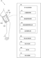
- FIG. 1 is a schematic diagram showing a blood pressure measuring device according to Embodiment 1 of the present invention.
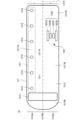
- FIG. 2 is a first diagram illustrating the appearance of the blood pressure measuring device according to the first embodiment.
- FIG. 3 is a second diagram illustrating the appearance of the blood pressure measurement device according to the first embodiment.
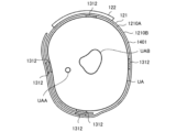
- FIG. 4 is a diagram illustrating a cross section of the blood pressure measurement device according to Embodiment 1.
- FIG. 5 is a block diagram illustrating the hardware configuration of the control system of the blood pressure measurement device according to the first embodiment;
- FIG. 6 is a block diagram illustrating the software configuration of the blood pressure measurement device according to the first embodiment;
- FIG. 7 is a flowchart illustrating an example of the flow of processing by the blood pressure measurement device according to the first embodiment;
- FIG. 8 is a schematic diagram showing a blood pressure measurement system according to Embodiment 2 of the present invention.
- FIG. 9 is a block diagram showing a schematic functional configuration of each element of the blood pressure measurement system according to the second embodiment.
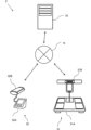
- FIG. 10 is a schematic diagram showing a blood pressure measurement system according to Embodiment 3 of the present invention.
- FIG. 11 is a block diagram showing a schematic functional configuration of each element of the blood pressure measurement system according to the third embodiment.
- FIG. 1 is a schematic diagram illustrating a blood pressure measurement device 10 according to one embodiment.
- the blood pressure measurement device 10 is a wearable device and is worn on the user's upper arm, which is the part to be measured.
- the blood pressure measurement device 10 generally includes a belt section 120 , a first blood pressure measurement section 130 , a second blood pressure measurement section 140 , a calibration determination section 150 , an instruction section 160 and a calibration processing section 170 .
- the belt portion 120 includes a belt 121 and a main body 122.
- the belt 121 refers to a belt-like member worn around the upper arm, and is also called by another name such as a band or a cuff.
- Belt 121 has an inner peripheral surface and an outer peripheral surface.
- the inner peripheral surface is the surface that contacts the user's upper arm when the user wears the blood pressure measuring device 10 (hereinafter simply referred to as the "wearing state")
- the outer peripheral surface is the surface on the opposite side of the inner peripheral surface. be.
- the first blood pressure measurement unit 130 noninvasively measures the user's pulse wave transit time and calculates the blood pressure value based on the measured pulse wave transit time (PTT).
- PTT pulse wave transit time
- the blood pressure value calculated based on the pulse wave transit time is also referred to as an estimated blood pressure value.
- the first blood pressure measurement unit 130 may perform continuous blood pressure measurement to obtain a blood pressure value for each heartbeat.
- the second blood pressure measurement unit 140 measures blood pressure using a method different from that of the first blood pressure measurement unit 130 . Specifically, the second blood pressure measurement unit 140 measures blood pressure, for example, by the oscillometric method or the Korotkoff method, at a specific timing, for example, in response to an operation by the user. The second blood pressure measurement unit 140 cannot measure blood pressure continuously, but it can measure blood pressure more accurately than the first blood pressure measurement unit 130 . Below, the blood pressure value measured by the second blood pressure measurement unit 140 is also referred to as a measured blood pressure value.
- the first blood pressure measurement unit 130 includes functional modules of an electrocardiogram acquisition unit 131, a pulse wave signal acquisition unit 132, a pulse wave propagation time calculation unit 133, and a blood pressure value calculation unit .
- the electrocardiogram acquisition unit 131 has a plurality of electrodes and acquires the user's electrocardiogram (ECG) using these electrodes.
- An electrocardiogram represents the electrical activity of the heart.
- Electrodes are provided on the belt portion 120 .
- the electrodes are arranged on the inner peripheral surface of the belt 121 so that the electrodes are in contact with the skin of the user's upper arm when worn.
- the pulse wave signal acquisition unit 132 includes a pulse wave sensor and acquires a pulse wave signal representing the user's pulse wave using the pulse wave sensor.
- a pulse wave sensor is provided on the belt portion 120 .
- the pulse wave sensor is arranged on the inner peripheral surface of the belt 121 so that the pulse wave sensor contacts the skin of the user's upper arm when worn.
- Some types of pulse wave sensors such as pulse wave sensors based on the Radio Law, which will be described later, do not need to be in contact with the skin of the user's upper arm when worn.
- the pulse wave transit time calculation unit 133 calculates the pulse wave based on the time difference between the waveform feature point of the electrocardiogram acquired by the electrocardiogram acquisition unit 131 and the waveform feature point of the pulse wave signal acquired by the pulse wave signal acquisition unit 132. Calculate the propagation time. For example, the pulse wave transit time calculator 133 calculates the time difference between the waveform feature point of the electrocardiogram and the waveform feature point of the pulse wave signal, and outputs the calculated time difference as the pulse wave transit time.
- the pulse wave propagation time corresponds to the time required for the pulse wave to propagate through the artery from the heart to the upper arm (specifically, the position where the pulse wave sensor is arranged).
- the blood pressure value calculator 134 calculates the blood pressure value based on the pulse wave transit time calculated by the pulse wave transit time calculator 133 and the blood pressure calculation formula.
- the blood pressure calculation formula is a relational expression representing the correlation between the pulse wave transit time and the blood pressure.
- SBP represents systolic blood pressure
- PTT represents pulse wave transit time
- a 1 and A 2 are parameters.
- the pulse wave propagation time calculation unit 133 can calculate the pulse wave propagation time for each heartbeat, and therefore the blood pressure value calculation unit 134 can calculate the blood pressure value for each heartbeat.
- the calibration determination unit 150 monitors a predetermined feature amount (for example, PTT in this embodiment) acquired by the first blood pressure measurement unit 130, and the feature amount deviates from a predetermined reference value (for example, upper and lower threshold values). Determine whether or not Then, when it is determined that the feature amount deviates from the predetermined reference value, it is determined to acquire the measured blood pressure value of the user.
- a predetermined feature amount for example, PTT in this embodiment
- the instruction unit 160 outputs information instructing execution of blood pressure measurement by the second blood pressure measurement unit 140 when the calibration determination unit 150 determines to acquire the measured blood pressure value. For example, the instruction unit 160 outputs a notification sound (for example, a melody) through a sounding body and causes the display unit 1222 to display a message “Please perform blood pressure measurement”. When the user presses a predetermined button in response to an instruction from instruction unit 160, blood pressure measurement by second blood pressure measurement unit 140 is performed. Blood pressure measurement by the second blood pressure measurement unit 140 will be described later.
- the calibration processing unit 170 calibrates the blood pressure calculation formula (1) based on the measured blood pressure value measured by the second blood pressure measurement unit 140 . Since the correlation between the pulse wave transit time and the blood pressure represented by the blood pressure calculation formula differs for each individual user, it is necessary to calibrate the blood pressure calculation formula for each user. Calibration of the blood pressure calculation formula (specifically, determination of parameters A 1 and A 2 ) is performed based on measured blood pressure values obtained by second blood pressure measurement section 140 . The details of the calibration of the blood pressure calculation formula will be described later.
- the time difference between the waveform characteristic point of the electrocardiogram and the waveform characteristic point of the pulse wave signal related to the upper arm is calculated as the pulse wave propagation time.
- the pulse wave transit time obtained by the blood pressure measuring device 10 is a large value compared to the case of measuring the pulse wave transit time between two points on the upper arm. In other words, a longer pulse wave propagation distance is ensured. Therefore, the influence of the error generated when calculating the time difference between the waveform characteristic point of the electrocardiogram and the waveform characteristic point of the pulse wave signal on the pulse wave transit time is reduced, and the pulse wave transit time can be measured accurately. be able to. As a result, the reliability of the blood pressure value obtained by blood pressure measurement based on the pulse wave transit time is improved.
- the belt 121 has a mounting member that allows the belt 121 to be attached to and detached from the upper arm.
- the mounting member is a hook and loop fastener having a loop surface 1213 with multiple loops and a hook surface 1214 with multiple hooks.
- the loop surface 1213 is arranged on the outer peripheral surface 1211 of the belt 121 and at the longitudinal end portion 1215A of the belt 121 .
- the longitudinal direction corresponds to the circumferential direction of the upper arm when worn.
- the hook surface 1214 is arranged on the inner peripheral surface 1212 of the belt 121 and at the longitudinal end portion 1215B of the belt 121 . End 1215B faces end 1215A in the longitudinal direction of belt 121 .
- the number of electrodes 1312 is not limited to six, and may be two to five or seven or more. If two or three electrodes 1312 are in contact with the upper arm, the electrocardiogram may not be measured well depending on the wearing state. If the electrocardiogram cannot be measured successfully, it is necessary to display a message on the display unit 1222 or the like to have the user wear the blood pressure measurement device 10 again. In order to avoid a situation in which an electrocardiogram cannot be measured, it is desired that at least four electrodes 1312 are in contact with the upper arm when worn.
- the electrode 1312 is located on the central portion 1217A of the belt 121, as shown in FIG.
- the center side portion 1217A is a portion located closer to the center (shoulder side) than the center line 1216 in the worn state. More preferably, the electrode 1312 is arranged at the center side end 1218A of the belt 121 .
- the center side end portion 1218A is an end portion located on the center side in the worn state, and the width of the center side end portion 1218A is, for example, one third of the total width of the belt 121 .
- a sensor portion 1322 of a pulse wave sensor 1321 for measuring pulse waves is further arranged on the inner peripheral surface 1212 of the belt 121 .
- sensor unit 1322 includes a pair of electrodes 1323A and 1323D for energizing the upper arm and a pair of electrodes 1323B and 1323C for detecting voltage.
- Electrodes 1323A, 1323B, 1323C, and 1323D are arranged in the width direction of belt 121 in this order.
- the width direction of the belt 121 is the direction along the brachial artery UAA in the worn state.
- sensor portion 1322 is located on distal portion 1217B of belt 121 .
- the distal side portion 1217B is a portion located on the distal side (elbow side) of the center line 1216 in the worn state. More preferably, sensor portion 1322 is arranged at distal end portion 1218C of belt 121 .
- the distal end portion 1218C is the end portion located on the distal side in the worn state, and the width of the distal end portion 1218C is, for example, one-third of the total width of the belt 121 .
- the portion between the central end 1218A and the distal end 1218C is referred to as the intermediate portion 1218B.
- the belt 121 includes an inner cloth 1210A, an outer cloth 1210B, and a pressure cuff 1401 provided between the inner cloth 1210A and the outer cloth 1210B.
- the pressure cuff 1401 is a long band in the longitudinal direction of the belt 121 so as to enclose the upper arm.
- the pressure cuff 1401 is configured as a fluid bag by arranging two stretchable polyurethane sheets facing each other in the thickness direction and welding their peripheries.
- the electrode group 1311 and the sensor section 1322 are provided on the inner cloth 1210A so as to be positioned between the pressure cuff 1401 and the upper arm UA in the worn state.
- FIG. 5 illustrates an example of the hardware configuration of the control system of the blood pressure measurement device 10 according to this embodiment.
- the main body 122 includes a control unit 1501, a storage unit 1505, a battery 1506, a switch circuit 1313, a subtraction circuit 1314, and an analog front end (AFE) 1315.
- AFE analog front end
- a pressure sensor 1402, a pump 1403, a valve 1404, an oscillator circuit 1405, and a pump drive circuit 1406 are mounted.
- the pulse wave sensor 1321 includes an energization and voltage detection circuit 1324 in addition to the sensor section 1322 described above. In this example, the energization and voltage detection circuit 1324 is mounted on the belt 121 .
- a control unit 1501 includes a CPU (Central Processing Unit) 1502, a RAM (Random Access Memory) 1503, a ROM (Read Only Memory) 1504, etc., and controls each component according to information processing.
- Storage unit 1505 is, for example, an auxiliary storage device such as a hard disk drive (HDD) or a semiconductor memory (e.g., flash memory), and contains programs executed by control unit 1501 (e.g., pulse wave transit time measurement program and blood pressure measurement program). ), setting data necessary for executing the program, blood pressure measurement results, etc. are stored in a non-volatile manner.
- a storage medium included in the storage unit 1505 stores information such as a program electrically, magnetically, optically, mechanically, or chemically so that the information such as the program recorded can be read by a computer, other device, machine, or the like. It is a medium that accumulates due to the action of Note that part or all of the program may be stored in the ROM 1504 .
- a battery 1506 supplies power to components such as the control unit 1501 .
- Battery 1506 is, for example, a rechargeable battery.
- Each electrode 1312 included in the electrode group 1311 is connected to an input terminal of a switch circuit 1313 .
- Two output terminals of the switch circuit 1313 are connected to two input terminals of the subtraction circuit 1314, respectively.
- the switch circuit 1313 receives a switch signal from the control section 1501 and connects two electrodes 1312 specified by the switch signal to the subtraction circuit 1314 .
- the subtraction circuit 1314 subtracts the potential input from one input terminal from the potential input from the other input terminal.
- Subtraction circuit 1314 outputs a potential difference signal representing the potential difference between two electrodes 1312 connected to AFE 1315 .
- the subtraction circuit 1314 is, for example, an instrumentation amplifier.
- AFE 1315 includes, for example, a low pass filter (LPF), an amplifier, and an analog-to-digital converter.
- the potential difference signal is filtered by an LPF, amplified by an amplifier, and converted to a digital signal by an analog-to-digital converter.
- the potential difference signal converted into a digital signal is provided to control section 1501 .
- the control unit 1501 acquires the potential difference signal output from the AFE 1315 in time series as an electrocardiogram.
- the energization and voltage detection circuit 1324 causes a high-frequency constant current to flow between the electrodes 1323A and 1323D.
- the current frequency is 50 kHz and the current value is 1 mA.
- the energization and voltage detection circuit 1324 detects the voltage between the electrodes 1323B and 1323C while the electrodes 1323A and 1323D are energized, and generates a detection signal.
- the detection signal represents a change in electrical impedance caused by a pulse wave propagating through the arterial portion facing electrodes 1323B and 1323C.
- the energization and voltage detection circuit 1324 subjects the detection signal to signal processing including rectification, amplification, filtering, and analog-to-digital conversion, and supplies the detection signal to the control section 1501 .
- the control unit 1501 acquires detection signals output in time series from the energization and voltage detection circuit 1324 as pulse wave signals.
- valve 1404 When the valve 1404 is open, the pressure cuff 1401 communicates with the atmosphere and the air in the pressure cuff 1401 is exhausted to the atmosphere. In addition, the valve 1404 has a function of a check valve, and air does not flow back.
- Pump drive circuit 1406 drives pump 1403 based on a control signal received from control section 1501 .
- the pressure sensor 1402 detects the pressure (also referred to as cuff pressure) within the pressing cuff 1401 and generates an electrical signal representing the cuff pressure.
- the cuff pressure is, for example, pressure based on atmospheric pressure.
- Pressure sensor 1402 is, for example, a piezoresistive pressure sensor.
- Oscillation circuit 1405 oscillates based on the electrical signal from pressure sensor 1402 and outputs a frequency signal having a frequency corresponding to the electrical signal to control section 1501 .
- the output of pressure sensor 1402 is used to control the pressure of pressure cuff 1401 and to calculate blood pressure values (including systolic and diastolic pressure) by oscillometric methods.
- the pressing cuff 1401 may be used to adjust the contact state between the electrode 1312 or the sensor unit 1322 of the pulse wave sensor 1321 and the upper arm UA. For example, when performing blood pressure measurement based on the pulse wave transit time, the pressure cuff 1401 is kept in a state containing a certain amount of air. As a result, the electrode 1312 and the sensor portion 1322 of the pulse wave sensor 1321 are brought into contact with the upper arm UA without fail.
- the electrode group 1311, the switch circuit 1313, the subtraction circuit 1314, and the AFE 1315 correspond to the electrocardiogram acquisition unit 131 of the first blood pressure measurement unit 130 shown in FIG. 1321 (the electrode 1323 and the energization and voltage detection circuit 1324 ) corresponds to the pulse wave signal acquisition section 132 of the first blood pressure measurement section 130 .
- the pressure cuff 1401 , the pressure sensor 1402 , the pump 1403 , the valve 1404 , the oscillation circuit 1405 and the pump drive circuit 1406 correspond to the second blood pressure measurement section 140 .
- the controller 1501 may include multiple processors.
- the blood pressure measurement device 10 may include a communication unit 1507 for communicating with an external device such as a user's mobile terminal (for example, smart phone).
- Communication unit 1507 includes a wired communication module and/or a wireless communication module.
- a wireless communication method for example, Bluetooth (registered trademark), BLE (Bluetooth Low Energy), or the like can be adopted.
- FIG. 6 illustrates an example of the software configuration of the blood pressure measurement device 10 according to this embodiment.
- the blood pressure measurement apparatus 10 includes an electrocardiogram measurement control unit 1601, an electrocardiogram storage unit 1602, a pulse wave measurement control unit 1603, a pulse wave signal storage unit 1604, a pulse wave transit time calculation unit 133, and a blood pressure value calculation unit 134.
- blood pressure calculation formula storage unit 1605 estimated blood pressure value storage unit 1606, calibration determination unit 150, instruction unit 160, blood pressure measurement control unit 1608, measured blood pressure value storage unit 1609, display control unit 1607, instruction input unit 1610, calibration processing unit 170 and a calibration judgment reference value storage unit 1611 .
- Electrocardiogram measurement control unit 1601, pulse wave measurement control unit 1603, pulse wave transit time calculation unit 133, blood pressure value calculation unit 134, calibration determination unit 150, instruction unit 160, blood pressure measurement control unit 1608, display control unit 1607, instruction input unit 1610 and the calibration processing unit 170 execute the following processes when the control unit 1501 of the blood pressure measurement device 10 executes the program stored in the storage unit 1505 .
- the control unit 1501 executes the program, the control unit 1501 develops the program on the RAM 1503 . Then, the control unit 1501 interprets and executes the program developed in the RAM 1503 by the CPU 1502 to control each component.
- the electrocardiogram storage unit 1602, the pulse wave signal storage unit 1604, the blood pressure calculation formula storage unit 1605, the estimated blood pressure value storage unit 1606, the measured blood pressure value storage unit 1609, and the calibration judgment reference value storage unit 1611 are realized by the storage unit 1505. .
- the electrocardiogram measurement control unit 1601 controls the switch circuit 1313 to acquire an electrocardiogram. Specifically, electrocardiogram measurement control section 1601 generates a switch signal for selecting two electrodes 1312 out of six electrodes 1312 and provides this switch signal to switch circuit 1313 . The electrocardiogram measurement control unit 1601 acquires potential difference signals obtained using the two selected electrodes 1312, and stores time-series data of the acquired potential difference signals as an electrocardiogram in the electrocardiogram storage unit 1602.
- the electrocardiogram measurement control unit 1601 determines the optimum electrode pair for obtaining an electrocardiogram. For example, the electrocardiogram measurement control unit 1601 acquires an electrocardiogram for each of all electrode pairs, and determines the electrode pair that provides the electrocardiogram with the largest R-wave amplitude as the optimum electrode pair. After that, the electrocardiogram measurement control unit 1601 uses the optimum electrode pair to measure the electrocardiogram.
- a pulse wave measurement control unit 1603 controls an energization and voltage detection circuit 1324 to acquire a pulse wave signal. Specifically, the pulse wave measurement control unit 1603 instructs the energization and voltage detection circuit 1324 to apply a current between the electrodes 1323A and D, and the detected electrode 1323B with the current applied between the electrodes 1323A and D. , 1323C. Pulse wave measurement control section 1603 causes pulse wave signal storage section 1604 to store the time-series data of the detection signal as a pulse wave signal.
- the pulse wave propagation time calculation unit 133 reads the electrocardiogram from the electrocardiogram storage unit 1602, reads the pulse wave signal from the pulse wave signal storage unit 1604, and calculates the time difference between the waveform characteristic point of the electrocardiogram and the waveform characteristic point of the pulse wave signal.
- pulse wave transit time is calculated based on For example, the pulse wave propagation time calculation unit 133 detects the time (time) of the peak point corresponding to the R wave from the electrocardiogram, detects the time (time) of the rising point from the pulse wave signal, and detects the peak time from the time of the rising point.
- the pulse wave transit time is calculated by subtracting the point time.
- the pulse wave transit time calculation unit 133 may correct the above time difference based on the pre-ejection period (PEP) and output the corrected time difference as the pulse wave transit time. For example, assuming that the pre-ejection period is constant, the pulse wave transit time calculator 133 may calculate the pulse wave transit time by subtracting a predetermined value from the above time difference.
- PEP pre-ejection period
- the peak point corresponding to the R wave is an example of the waveform characteristic point of the electrocardiogram.
- the waveform characteristic point of the electrocardiogram may be a peak point corresponding to the Q wave or a peak point corresponding to the S wave. Since the R-wave appears as a distinct peak compared to the Q-wave or S-wave, the time of the R-wave peak point can be identified more accurately. Therefore, preferably, the R-wave peak point is used as the waveform feature point of the electrocardiogram.
- the rising point is an example of a waveform characteristic point of the pulse wave signal.
- the waveform feature point of the pulse wave signal may be a peak point. Since the pulse wave signal slowly changes over time, an error is likely to occur when identifying the time of the waveform feature point in the pulse wave signal.
- the blood pressure value calculator 134 calculates an estimated blood pressure value based on the pulse wave transit time calculated by the pulse wave transit time calculator 133 and the blood pressure calculation formula.
- the blood pressure value calculation unit 134 uses the blood pressure value calculation algorithm (specifically, for example, the above formula (1)) stored in the blood pressure calculation formula storage unit 1605 as the blood pressure calculation formula.
- the blood pressure value calculation unit 134 stores the calculated blood pressure value in the estimated blood pressure value storage unit 1606 in association with the time information.
- the blood pressure calculation formula is not limited to the above formula (1).
- the calibration determination unit 150 calculates a predetermined feature amount related to blood pressure estimation, for example, the pulse wave transit time calculated by the pulse wave transit time calculation unit 133, and the feature amount stored in the calibration determination reference value storage unit 1611. Based on a predetermined reference value, it is determined whether or not conditions for recommending measurement of the user's blood pressure have been met. Even if the blood pressure calculation formula has been calibrated when the device is first used, the estimated It is also conceivable that the accuracy of the blood pressure value will be low.
- the calibration determination unit 150 may determine whether or not the blood pressure change rate exceeds a threshold value as a predetermined feature amount.
- the blood pressure change rate is, for example, the amount of change in blood pressure value per unit time. Specifically, the calibration determination unit 150 determines whether the difference obtained by subtracting the blood pressure value a unit time ago from the latest blood pressure value exceeds a threshold.
- the calibration determination unit 150 satisfies the conditional expression SBP 0 ⁇ SBP 1 >V th Determine whether or not
- the unit time is, for example, 30 seconds
- the threshold is, for example, 20 [mmHg].
- the above conditional expression can be transformed using equation (1) to be A 1 (1/PTT 0 2 ⁇ 1/PTT 1 2 )> Vth .
- the instruction unit 160 outputs information instructing execution of blood pressure measurement by the second blood pressure measurement unit 140 when the calibration determination unit 150 determines to acquire the measured blood pressure value. For example, the instruction unit 160 gives an instruction signal to the display control unit 1607 to cause the display unit 1222 to display a message prompting execution of blood pressure measurement. Furthermore, the instruction unit 160 outputs a control signal for controlling a driving circuit that drives the sounding body in order to generate notification sound. Note that the instruction unit 160 may transmit an instruction signal to the user's portable terminal via the communication unit 1507, thereby prompting the user to perform blood pressure measurement through the portable terminal.
- the instruction input unit 1610 accepts instructions input by the user using the operation unit 1221 .
- instruction input section 1610 gives a blood pressure measurement start instruction to blood pressure measurement control section 1608 .
- the instruction input unit 1610 and the operation unit 1221 correspond to operation input means according to the present invention.
- Blood pressure values include, but are not limited to, systolic blood pressure (SBP) and diastolic blood pressure (DBP).
- SBP systolic blood pressure
- DBP diastolic blood pressure
- the blood pressure measurement control unit 1608 associates the calculated blood pressure value with the time information and stores it in the actually measured blood pressure value storage unit 1609 .
- the blood pressure measurement control unit 1608 can calculate the pulse rate at the same time as the blood pressure value.
- Blood pressure measurement control section 1608 stops pump 1403 via pump drive circuit 1406 when the calculation of the blood pressure value is completed. Air is thereby exhausted from the pressure cuff 1401 through the valve 1404 .
- the display control unit 1607 controls the display unit 1222.
- the display control unit 1607 receives an instruction signal from the instruction unit 160 and causes the display unit 1222 to display a message included in the instruction signal. Further, the display control unit 1607 causes the display unit 1222 to display the blood pressure measurement result after the blood pressure measurement by the blood pressure measurement control unit 1608 is completed.
- the calibration processing unit 170 calibrates the blood pressure calculation formula based on the estimated blood pressure value obtained by the blood pressure value calculation unit 134 and the measured blood pressure value obtained by the blood pressure measurement control unit 1608 .
- the calibration of the blood pressure calculation formula by the calibration processing unit 170 may be performed as an initial setting, for example, when the user wears the blood pressure measurement device 10 .
- the correlation between pulse wave transit time and blood pressure values varies from individual to individual.
- the correlation changes according to the state in which the blood pressure measurement device 10 is worn on the upper arm of the user. For example, even for the same user, the correlation changes when the blood pressure measurement device 10 is placed closer to the shoulder and when the blood pressure measurement device 10 is placed closer to the elbow.
- the blood pressure calculation formula is calibrated to reflect such changes in correlation.
- the calibration processing unit 170 also changes the reference values stored in the calibration judgment reference value storage unit 1611 . Specifically, for example, the difference between the estimated blood pressure value when the calibration determination unit 150 decides to acquire the measured blood pressure value and the measured blood pressure value is calculated. Change the reference value to increase, and if the difference is small, change the reference value to perform calibration less frequently.
- this embodiment describes an example in which all functions of the blood pressure measurement device 10 are realized by a general-purpose processor. However, part or all of the functionality may be implemented by one or more dedicated processors.
- FIG. 7 is a flowchart showing an example of the flow of processing performed by the blood pressure measurement device 10.
- the blood pressure calculation formula is calibrated for the first time (S101).
- the controller 1501 operates as the calibration processor 170 .
- the number of parameters included in the blood pressure calculation formula is N, N or more pairs of pulse wave transit time measurement values and blood pressure measurement values are required.
- the above blood pressure calculation formula (1) has two parameters A 1 and A 2 .
- the control unit 1501 acquires a set of measured values of pulse wave transit time and blood pressure when the user is at rest, then causes the user to exercise, Obtain a set of measurements and blood pressure measurements. As a result, two sets of measured value of pulse wave transit time and measured value of blood pressure are obtained. The control unit 1501 determines the parameters A 1 and A 2 based on the obtained two sets of the pulse wave transit time measurement value and the blood pressure measurement value.
- a reference value is also set for determining the necessity of acquisition of the measured blood pressure value (S102).
- the reference value at this time may be calculated according to the determined parameters A 1 and A 2 , or may be set as a general-purpose reference value.
- the reference value set here is stored in the calibration judgment reference value storage unit 1611 .
- the blood pressure measurement (estimation) based on the pulse wave transit time becomes executable, and the following loop processing L1 is repeated until a predetermined termination condition is satisfied, whereby continuous and non-invasive blood pressure measurement is performed. is executed.
- the control unit 1501 continuously calculates the pulse wave transit time for calculating the estimated blood pressure value (S103). Further, an estimated blood pressure value is calculated based on the calculated pulse wave propagation time and the blood pressure calculation formula stored in the blood pressure calculation formula storage unit (S104). Then, it is determined whether or not the calculated pulse wave propagation time deviates from the reference value stored in the calibration determination reference value storage unit 1611 (S105).
- the reference value may be, for example, an upper threshold value or a lower threshold value of the pulse wave propagation time. Alternatively, it may be an upper and lower limit threshold that defines a predetermined numerical range.
- step S105 if the reference value is the upper threshold, whether or not it exceeds the reference value, if the reference value is the lower threshold, whether it is less than the reference value, and if the reference value is the upper and lower threshold, is within a predetermined numerical range therebetween.
- step S105 If it is determined in step S105 that the value does not deviate from the reference value, the process returns to step S103 and the subsequent processes are repeated. On the other hand, if it is determined in step S105 that the value deviates from the reference value, the process advances to step S106 to determine that the measured blood pressure value by the second blood pressure measurement unit 140 should be acquired for calibration of the blood pressure calculation formula. . Note that the control unit 1501 functions as the calibration determination unit 150 in the process of step S105.
- step S106 the control unit 1501 performs control for outputting information instructing the second blood pressure measurement unit 140 to perform blood pressure measurement.
- the control unit 1501 operates as the instruction unit 160 .
- a process of acquiring the measured blood pressure value by the second blood pressure measurement unit 140 is performed (S107).
- control section 1501 operates as blood pressure measurement control section 1608 .
- control unit 1501 calibrates the blood pressure calculation formula stored in the blood pressure calculation formula storage unit 1605 based on this (S108), and compares the estimated blood pressure value and the measured blood pressure value. A process of determining whether or not the difference is equal to or greater than a predetermined threshold is executed (S109).
- the reference value stored in the calibration determination reference value storage unit 1611 is changed so as to increase the frequency with which the instruction unit 160 instructs acquisition of the measured blood pressure value (S110). .
- the reference value is the upper and lower thresholds of the pulse wave transit time
- the upper threshold is decreased and the lower threshold is increased, that is, the numerical range determined by the upper and lower thresholds is reduced. . This makes it easier for the calculated pulse wave propagation time to deviate from the upper and lower thresholds than before the reference value is changed, and as a result, the instruction unit 160 instructs acquisition of the measured blood pressure value more frequently.
- step S111 if it is determined in step S108 that the difference is less than the threshold, the reference value is changed so that the frequency with which the instruction unit 160 instructs acquisition of the measured blood pressure value is decreased (S111).
- the reference value is the upper and lower thresholds of the pulse wave propagation time
- the upper threshold is increased and the lower threshold is decreased, that is, the upper and lower thresholds Change to expand the numerical range to be determined.
- the calculated pulse wave transit time is less likely to deviate from the upper and lower thresholds than before the change in the reference value, and as a result, the frequency with which instruction unit 160 instructs acquisition of the measured blood pressure value is reduced.
- step S110 or step S111 When the processing of step S110 or step S111 is executed, the series of loop processing L1 ends, and the loop processing L1 is returned to the start point (that is, step S103) and a new loop processing L1 is executed.
- the control unit 1501 functions as the calibration processing unit 170 in the processing from step S108 to step S111.
- step S109 it is determined whether or not the difference between the measured blood pressure value and the estimated blood pressure value is equal to or greater than a predetermined threshold.
- the order may be changed so that the process of determining whether or not the difference between the measured blood pressure value and the estimated blood pressure value is equal to or greater than a predetermined threshold value may be performed first.
- the difference is less than a predetermined threshold, it is possible not to calibrate the blood pressure calculation formula.
- the reference value is changed so as to increase the frequency of calibration; otherwise, the reference value is changed so as to decrease the frequency of calibration.
- the threshold may be set as an upper limit and a lower limit. That is, if the difference is equal to or greater than the upper threshold, the reference value is changed to increase the frequency of calibration; if the difference is equal to or less than the lower threshold, the reference value is changed to decrease the frequency of calibration; If it does not deviate from the threshold, the reference value may not be changed.
- both the electrode group 1311 and the sensor section 1322 of the pulse wave sensor 1321 are provided on the belt 121 . Therefore, both the electrode group 1311 and the pulse wave sensor 1321 are attached to the user by simply wrapping the belt 121 around the upper arm. Therefore, the user can easily wear the blood pressure measuring device 10 . Since the user only needs to wear one device, the user's reluctance to wear the blood pressure measurement device 10 is reduced.
- the blood pressure measurement device 10 since the blood pressure measurement device 10 is worn on the upper arm, blood pressure measurement is performed at approximately the same height as the heart. This eliminates the need to perform height correction on the acquired blood pressure measurement result. Moreover, when the blood pressure measurement device 10 is an upper arm type, the blood pressure measurement device 10 can be hidden by the sleeve of the clothes, and the blood pressure measurement device 10 can be worn inconspicuously.
- the pulse wave transit time is calculated based on the electrocardiogram and the pulse wave signal obtained for the upper arm, the pulse wave transit time for the long distance from the heart to the upper arm can be obtained. This improves robustness against errors that occur when calculating the time difference between the waveform characteristic point of the electrocardiogram and the waveform characteristic point of the pulse wave signal.
- the electrode group 1311 is arranged on the central side portion 1217A of the belt 121, and the sensor portion 1322 of the pulse wave sensor 1321 is arranged on the peripheral side portion 1217B of the belt 121. This arrangement ensures a longer pulse wave propagation distance and obtains a high signal-to-noise electrocardiogram. This further improves robustness. As a result, it is possible to accurately measure the pulse wave transit time, improving the reliability of the blood pressure value calculated based on the pulse wave transit time.
- blood pressure measurement based on the pulse wave transit time and blood pressure measurement by the oscillometric method can be performed with one device, which is highly convenient for the user. Since the second blood pressure measurement unit 140 is integrated with the first blood pressure measurement unit 130 and the blood pressure calculation formula is calibrated based on the measured blood pressure value obtained by the second blood pressure measurement unit 140, the blood pressure measurement device 10 alone can calibrate the blood pressure calculation formula. Therefore, it is possible to easily calibrate the blood pressure calculation formula.
- the first blood pressure measurement unit 130 determines whether or not the measured blood pressure value of the user should be acquired (that is, whether or not the algorithm for calculating the blood pressure value needs to be calibrated). If the determination is made and the condition is satisfied, the user is notified that blood pressure measurement should be performed by the second blood pressure measurement unit 140 . Therefore, it is possible to allow the user to perform accurate blood pressure measurement under circumstances where blood pressure measurement is recommended.
- the reference value of the predetermined feature amount which is the criterion for determining whether or not the measured blood pressure value should be acquired, is changed according to the difference value between the measured blood pressure value and the estimated blood pressure value (that is, the accuracy of the estimated blood pressure value). Therefore, the frequency of acquiring the measured blood pressure value can be optimized. In this way, it is possible to repeatedly calibrate the blood pressure value calculation algorithm to improve the accuracy of blood pressure estimation according to the user, and to provide a technique capable of optimizing the frequency of calibrating the blood pressure value calculation algorithm. can be done.
- the blood pressure measuring device 10 includes a pressure cuff for adjusting the contact state between the sensor portion 1322 of the pulse wave sensor 1321 and the upper arm, a pump for supplying air to the pressure cuff, a pump drive circuit for driving the pump, and the and a pressure sensor that detects pressure within the pressure cuff.
- This pressure cuff is provided at the distal end 1218C of the belt 121 .
- the pressure cuff 1401 is provided at the intermediate portion 1218B of the belt 121, for example.
- a pulse wave transit time measuring device comprising a belt unit 120, an electrocardiogram acquiring unit 131, a pulse wave signal acquiring unit 132, and a pulse wave transit time calculating unit 133.
- This pulse wave transit time measurement device may further include a calibration determination section 150 and an instruction section 160 .
- the pulse wave transit time measurement device may further comprise a pressure cuff, a pump, and a pump drive circuit to press the electrode 1312 and pulse wave sensor 1321 against the upper arm.
- the blood pressure measurement device 10 does not have to include the second blood pressure measurement section 140 .
- a blood pressure value obtained by measuring with another blood pressure monitor is input to the blood pressure measurement device 10 in order to calibrate the blood pressure calculation formula. There is a need.
- Embodiment 2 In Embodiment 1, the present invention is applied as a blood pressure measuring device, and all functions including the storage unit, blood pressure value calculation unit, display unit, etc. are integrated into one device. can also be applied as a blood pressure measurement system in which some of these configurations and functions are separated. 8 and 9 show examples of such a blood pressure measurement system.
- FIG. 8 shows an outline of the blood pressure measurement system 2 according to this embodiment.
- the blood pressure measurement system 2 includes a sensor device 21 worn on the user's upper arm, and an information processing terminal 22 that processes biological information acquired by the sensor device 21 .
- the sensor device 21 is a wearable device that includes a plurality of electrodes (electrocardiographic sensor) and a pulse wave sensor (not shown), and is used by being fixed to the user's upper arm by a fixing means such as a belt.
- the information processing terminal 22 may be of any type as long as it can communicate with the sensor device 21.
- a smart phone can be used as the information processing terminal 22 as shown in FIG.
- the storage unit 213 only has main storage devices such as RAM and ROM, and its storage capacity is limited.
- the operation unit 214 also has a limited configuration such as a power switch, and is simply configured.
- the power supply unit 215 can be, for example, a rechargeable secondary battery.
- the communication unit 216 includes a wired communication module and/or a wireless communication module. Note that the connection terminal for wired communication may also serve as the charging terminal of the power supply unit 215 .
- the sensor device 21 in this embodiment is configured to have only a very limited function for acquiring biological information for calculating an estimated blood pressure value. Therefore, the electrocardiogram signal and the pulse wave signal measured by each sensor unit are transmitted to the information processing terminal 22 via the communication unit 216 in real time.
- the information processing terminal 22 includes functional units such as a control unit 220 , a display unit 225 , an operation unit 226 , a communication unit 227 and a storage unit 228 .
- the control unit 220 also includes functional modules of a blood pressure value calculation unit 221 , a calibration determination unit 222 , a measured blood pressure value acquisition unit 223 , and a calibration processing unit 224 .
- the information processing terminal 22 communicates with the sensor device 21 via the communication unit 227 and receives the user's electrocardiogram signal and pulse wave signal measured by the sensor device 21 .
- the communication standard is not particularly limited, communication can be performed according to wireless communication standards such as Bluetooth (registered trademark), Wi-Fi (registered trademark), and infrared communication.
- the hardware configuration of the information processing terminal 22 is the same as that of a smartphone, and for example, the touch panel display serves both as the display unit 225 and the operation unit 226 .
- the biological information received from the sensor device 21 via the communication unit 227 is stored in the storage unit 228, and each process such as calculation of the estimated blood pressure value is performed based on the stored information.
- the storage unit 228 stores not only an electrocardiogram and a pulse wave signal, but also an algorithm for calculating a blood pressure value, a reference value for determining whether or not calibration is necessary, an estimated Information such as blood pressure values and measured blood pressure values is stored.
- the blood pressure value calculation unit 221, the calibration determination unit 222, and the calibration processing unit 224 similarly to the blood pressure measurement device 10 of the first embodiment, each perform processing for calculating an estimated blood pressure value and determination of necessity of algorithm calibration using actual blood pressure values.
- This is a functional module that performs determination processing, algorithm calibration processing for blood pressure calculation, and reference value change processing for determining whether or not calibration is necessary. Since these processes are the same as those of the first embodiment, a repeated description is omitted here.
- the measured blood pressure value acquisition unit 223 executes a process of acquiring the measured blood pressure value when the calibration determination unit 222 determines that calibration of the blood pressure calculation algorithm using the measured blood pressure value is necessary.
- the user is notified that the measured blood pressure value should be input via the display unit 225 or a speaker (not shown).
- the user measures the actual blood pressure value using another device (not shown) capable of accurate blood pressure measurement such as an oscillometric method, and inputs the blood pressure value to the information processing terminal 22 by operating the operation unit 226. do. That is, the measured blood pressure value acquisition unit 223 acquires the measured blood pressure value via the operation unit 226 .
- the acquired measured blood pressure value is stored in the storage unit 228 .
- the sensor device 21 senses biological information (for example, an electrocardiogram and a pulse wave signal) for continuously calculating an estimated blood pressure value.
- Judgment processing, algorithm calibration processing, and the like are configured to be performed by the information processing terminal 22 .
- the configuration of the wearable device can be simplified, and the user's burden associated with wearing the device can be further reduced.
- existing information processing terminals such as smartphones can be used, the cost for users to introduce the system can be reduced.
- the blood pressure measurement device 32 is a general home-use blood pressure measurement device having a main body portion 32A and a cuff portion 32B. and an input unit such as an operation button.
- FIG. 11 is a block diagram showing the functional configuration of the blood pressure measurement system 3.
- the body composition analyzer includes an electrocardiogram acquisition unit 311 , a pulse wave signal acquisition unit 312 , a pulse wave propagation time calculation unit 313 , a blood pressure value calculation unit 314 , a calibration determination unit 315 , a storage unit 316 and a communication unit 317 .
- the electrocardiogram acquisition unit 311 acquires the electrocardiogram of the user via the electrodes arranged on the upper surface of the body part 31A and the handle part 31B of the body composition monitor 31.
- the pulse wave signal acquisition unit 312 acquires the user's pulse wave signal (peripheral pulse wave) via a pulse wave sensor arranged on the handle portion 31B.
- the pulse wave sensor may be of an impedance type or of a photoelectric type.
- the acquired electrocardiogram and pulse wave signal are stored in the storage unit 316 .
- the storage unit 316 stores a blood pressure calculation algorithm, a judgment reference value for whether or not calibration is necessary, and the like, similarly to the blood pressure measurement device 10 of the first embodiment.
- the pulse wave transit time calculation unit 313 reads the electrocardiogram and the pulse wave signal from the storage unit 316, and calculates the pulse wave transit time based on the time difference between the waveform feature point of the electrocardiogram and the waveform feature point of the pulse wave signal.
- the blood pressure value calculation unit 314 also calculates the blood pressure value based on the calculated pulse wave propagation time and the blood pressure calculation algorithm stored in the storage unit 316 .
- the calibration determination unit 315 determines whether the blood pressure calculation algorithm should be calibrated based on the calculated pulse wave transit time and the predetermined reference value stored in the storage unit 316 . Since each of these processes is the same as in the case of the blood pressure measurement device 10 of Embodiment 1, detailed description thereof will be omitted here.
- the blood pressure measurement device 32 includes a blood pressure measurement unit 321 and a communication unit 322 as functional units.
- the blood pressure measurement unit 321 is a functional unit that performs accurate blood pressure measurement by means such as an oscillometric method, and can have the same configuration as the second blood pressure measurement unit 140 in the blood pressure measurement device 10 of form 1. Description here is omitted.
- the measured blood pressure value measured by the blood pressure measurement unit 321 is transmitted to the server 33 via the communication unit 322 and the network N.
- the server 33 includes functional units of a calibration processing unit 331 , a storage unit 332 and a communication unit 333 .
- Information (estimated blood pressure value, measured blood pressure value, etc.) transmitted from the body composition monitor 31 and the blood pressure measurement device 32 and received by the communication unit 333 is stored in the storage unit 332 .
- the calibration processing unit 331 performs processing for calibrating the blood pressure calculation algorithm of the body composition meter 31 based on the estimated blood pressure value and the measured blood pressure value stored in the storage unit 332 . Specifically, a more appropriate parameter value is calculated based on the estimated blood pressure value and the measured blood pressure value, and the data of the new parameter calculated in this way is sent to the body composition analyzer via the communication unit 333 and the network N. 31. Then, the blood pressure calculation algorithm stored in the storage unit 316 of the body composition meter 31 is updated to a new algorithm using new parameters, thereby calibrating the blood pressure calculation algorithm.
- the calibration processing unit 331 also executes processing for changing the reference value used in the determination processing performed by the calibration determination unit 315, as in the first and second embodiments. Also for this, as in the calibration of the algorithm, the server 33 calculates a new reference value, transmits the calculated new reference value to the body composition analyzer 31, and stores the new reference value in the storage unit 316. Thus, the reference value is changed.
- the general-purpose body composition analyzer 31 is used to acquire biological information for calculating the estimated blood pressure value, instead of using a dedicated device. Also, the function of the calibration processing unit 331 is executed in the server 33 , not in the body composition analyzer 31 . This eliminates the need for complicated arithmetic processing on the measuring device side for algorithm calibration, so blood pressure values can be measured (estimated) using a general-purpose body composition analyzer, and the algorithm can be calibrated as appropriate. can also be done. That is, even if a general-purpose body composition meter is used, it is possible to keep the estimated blood pressure value highly accurate.
- the body composition monitor 31 is configured to include the handle portion 31B, but it is also possible to use a body composition monitor that does not include the handle portion 31B.
- the height at the point of inflection of the pulse wave or electrocardiogram, the slope between the two points of inflection, the area between the two points of inflection, the ratio of these points, etc. are the calibration requirements for the algorithm. It is good also as a feature-value for negative determination.
- information related to heartbeat for example, difference from previous beat, average value and difference of beat, etc.
- user individual attribute information for example, difference from previous beat, average value and difference of beat, etc.
- information related to the situation at the time of measurement user activity amount, posture, etc.
- environmental information season, external temperature, etc.
- both the upper and lower limit values are changed when the reference value is the upper and lower limit threshold value for the pulse wave transit time.
- pattern can be set.
- the reference value can be set as only the upper threshold or only the lower threshold.
- the frequency of calibration can be increased by increasing the reference value, and the frequency of calibration can be decreased by decreasing the reference value.
- the reference value is the upper and lower thresholds, only the upper threshold or only the lower threshold may be changed. Even in such a case, it is possible to change the width of the numerical range in which the feature amount should fall, and accordingly it is possible to change the frequency of calibration.
- 10 blood pressure measuring device, 120... Belt part, 121... Belt, 122... Main body, 130 first blood pressure measurement unit 131 electrocardiogram acquisition unit 132 pulse wave signal acquisition unit 133 pulse wave propagation time calculation unit 134 blood pressure value calculation unit 140... second blood pressure measurement unit, 150... calibration determination unit, 160... instruction unit, 1210A... Inner fabric 1210B... Outer fabric 1213... Loop surface 1214... Hook surface 1221... Operation part 1222... Display part 1311 ... electrode group, 1312 ... electrode, 1313 ... switch circuit, 1314 ... subtraction circuit, 1315 ... analog front end, 1321 ... pulse wave sensor, 1322 ... sensor unit, 1323A to 1323D ... electrode, 1324 ...
Landscapes
- Health & Medical Sciences (AREA)
- Life Sciences & Earth Sciences (AREA)
- Engineering & Computer Science (AREA)
- Cardiology (AREA)
- Medical Informatics (AREA)
- Animal Behavior & Ethology (AREA)
- Veterinary Medicine (AREA)
- Biophysics (AREA)
- Pathology (AREA)
- Public Health (AREA)
- Biomedical Technology (AREA)
- Heart & Thoracic Surgery (AREA)
- General Health & Medical Sciences (AREA)
- Molecular Biology (AREA)
- Surgery (AREA)
- Physics & Mathematics (AREA)
- Physiology (AREA)
- Vascular Medicine (AREA)
- Signal Processing (AREA)
- Ophthalmology & Optometry (AREA)
- Pulmonology (AREA)
- Artificial Intelligence (AREA)
- Computer Vision & Pattern Recognition (AREA)
- Psychiatry (AREA)
- Dentistry (AREA)
- Measuring Pulse, Heart Rate, Blood Pressure Or Blood Flow (AREA)
- Measurement And Recording Of Electrical Phenomena And Electrical Characteristics Of The Living Body (AREA)
Priority Applications (3)
| Application Number | Priority Date | Filing Date | Title |
|---|---|---|---|
| DE112022005870.6T DE112022005870T5 (de) | 2021-12-09 | 2022-12-06 | Blutdruckmessvorrichtung und blutdruckmesssystem |
| CN202280052469.2A CN117794443A (zh) | 2021-12-09 | 2022-12-06 | 血压测定装置和血压测定系统 |
| US18/442,775 US20240268766A1 (en) | 2021-12-09 | 2024-02-15 | Blood-pressure-measuring device and blood-pressure-measuring system |
Applications Claiming Priority (2)
| Application Number | Priority Date | Filing Date | Title |
|---|---|---|---|
| JP2021-199787 | 2021-12-09 | ||
| JP2021199787A JP7775682B2 (ja) | 2021-12-09 | 2021-12-09 | 血圧測定装置及び血圧測定システム |
Related Child Applications (1)
| Application Number | Title | Priority Date | Filing Date |
|---|---|---|---|
| US18/442,775 Continuation US20240268766A1 (en) | 2021-12-09 | 2024-02-15 | Blood-pressure-measuring device and blood-pressure-measuring system |
Publications (1)
| Publication Number | Publication Date |
|---|---|
| WO2023106295A1 true WO2023106295A1 (ja) | 2023-06-15 |
Family
ID=86730382
Family Applications (1)
| Application Number | Title | Priority Date | Filing Date |
|---|---|---|---|
| PCT/JP2022/044935 Ceased WO2023106295A1 (ja) | 2021-12-09 | 2022-12-06 | 血圧測定装置及び血圧測定システム |
Country Status (5)
| Country | Link |
|---|---|
| US (1) | US20240268766A1 (enExample) |
| JP (1) | JP7775682B2 (enExample) |
| CN (1) | CN117794443A (enExample) |
| DE (1) | DE112022005870T5 (enExample) |
| WO (1) | WO2023106295A1 (enExample) |
Families Citing this family (1)
| Publication number | Priority date | Publication date | Assignee | Title |
|---|---|---|---|---|
| CN120808653B (zh) * | 2025-09-12 | 2025-11-18 | 天津天堰科技股份有限公司 | 一种基于水银血压计进行模拟血压测量的方法及装置 |
Citations (4)
| Publication number | Priority date | Publication date | Assignee | Title |
|---|---|---|---|---|
| JP2007007077A (ja) * | 2005-06-29 | 2007-01-18 | Fukuda Denshi Co Ltd | 血圧監視装置 |
| JP2017170014A (ja) * | 2016-03-25 | 2017-09-28 | 京セラ株式会社 | 血圧推定装置、血圧計、血圧推定システム、及び血圧推定方法 |
| JP2020006089A (ja) * | 2018-07-12 | 2020-01-16 | オムロンヘルスケア株式会社 | 脈波伝播時間測定装置及び血圧測定装置 |
| JP2020028478A (ja) * | 2018-08-23 | 2020-02-27 | オムロンヘルスケア株式会社 | 脈波伝播時間測定装置及び血圧測定装置 |
Family Cites Families (9)
| Publication number | Priority date | Publication date | Assignee | Title |
|---|---|---|---|---|
| JP3858379B2 (ja) * | 1997-10-08 | 2006-12-13 | セイコーエプソン株式会社 | 心拍出量検出装置および心機能診断装置 |
| JP4754915B2 (ja) * | 2005-09-21 | 2011-08-24 | フクダ電子株式会社 | 血圧監視装置 |
| KR100820159B1 (ko) * | 2005-11-29 | 2008-04-10 | 엘지전자 주식회사 | 혈압측정 방법 및 장치 |
| JP5176849B2 (ja) * | 2008-10-06 | 2013-04-03 | オムロンヘルスケア株式会社 | 血圧情報表示装置、血圧情報表示システム、血圧情報表示方法および血圧情報表示プログラム |
| US9204809B2 (en) * | 2012-02-01 | 2015-12-08 | Hong Kong Applied Science and Technology Research Institute Company Limited | Blood pressure measuring device and method of calibrating thereof |
| KR102486700B1 (ko) * | 2015-08-11 | 2023-01-11 | 삼성전자주식회사 | 혈압 추정 방법 및 장치 |
| JP2017158610A (ja) * | 2016-03-07 | 2017-09-14 | セイコーエプソン株式会社 | 血圧測定装置および血圧測定方法 |
| CN107126201A (zh) * | 2017-03-31 | 2017-09-05 | 悦享趋势科技(北京)有限责任公司 | 非入侵式的连续血压检测方法、设备和装置 |
| JP7023752B2 (ja) * | 2018-03-14 | 2022-02-22 | オムロンヘルスケア株式会社 | 脈波伝播時間測定装置及び血圧測定装置 |
-
2021
- 2021-12-09 JP JP2021199787A patent/JP7775682B2/ja active Active
-
2022
- 2022-12-06 DE DE112022005870.6T patent/DE112022005870T5/de active Pending
- 2022-12-06 CN CN202280052469.2A patent/CN117794443A/zh active Pending
- 2022-12-06 WO PCT/JP2022/044935 patent/WO2023106295A1/ja not_active Ceased
-
2024
- 2024-02-15 US US18/442,775 patent/US20240268766A1/en active Pending
Patent Citations (4)
| Publication number | Priority date | Publication date | Assignee | Title |
|---|---|---|---|---|
| JP2007007077A (ja) * | 2005-06-29 | 2007-01-18 | Fukuda Denshi Co Ltd | 血圧監視装置 |
| JP2017170014A (ja) * | 2016-03-25 | 2017-09-28 | 京セラ株式会社 | 血圧推定装置、血圧計、血圧推定システム、及び血圧推定方法 |
| JP2020006089A (ja) * | 2018-07-12 | 2020-01-16 | オムロンヘルスケア株式会社 | 脈波伝播時間測定装置及び血圧測定装置 |
| JP2020028478A (ja) * | 2018-08-23 | 2020-02-27 | オムロンヘルスケア株式会社 | 脈波伝播時間測定装置及び血圧測定装置 |
Also Published As
| Publication number | Publication date |
|---|---|
| US20240268766A1 (en) | 2024-08-15 |
| JP7775682B2 (ja) | 2025-11-26 |
| CN117794443A (zh) | 2024-03-29 |
| DE112022005870T5 (de) | 2024-10-02 |
| JP2023085645A (ja) | 2023-06-21 |
Similar Documents
| Publication | Publication Date | Title |
|---|---|---|
| CN112584758B (zh) | 脉搏波传播时间测定装置以及血压测定装置 | |
| US12171530B2 (en) | Pulse transit time measuring apparatus and blood pressure measuring apparatus | |
| US11369276B2 (en) | Blood pressure measurement device | |
| US9326692B2 (en) | Blood pressure measurement device and blood pressure measurement method | |
| US11925442B2 (en) | Blood pressure information measuring system, blood pressure information measuring method, blood pressure information measuring program, blood pressure information measuring device, server device, computation method, and computation program | |
| CN112584763B (zh) | 测定装置 | |
| JP7118784B2 (ja) | 脈波伝播時間測定装置及び血圧測定装置 | |
| WO2021024460A1 (ja) | 血圧計 | |
| US20220218217A1 (en) | Blood pressure measurement system and blood pressure measurement method using the same | |
| US20240268766A1 (en) | Blood-pressure-measuring device and blood-pressure-measuring system | |
| JP7666248B2 (ja) | 生体状態推定装置 | |
| WO2023080143A1 (ja) | 生体情報測定装置 | |
| WO2023013720A1 (ja) | 生体情報測定装置および生体情報処理システム |
Legal Events
| Date | Code | Title | Description |
|---|---|---|---|
| 121 | Ep: the epo has been informed by wipo that ep was designated in this application |
Ref document number: 22904223 Country of ref document: EP Kind code of ref document: A1 |
|
| WWE | Wipo information: entry into national phase |
Ref document number: 202280052469.2 Country of ref document: CN |
|
| WWE | Wipo information: entry into national phase |
Ref document number: 202417007762 Country of ref document: IN |
|
| 122 | Ep: pct application non-entry in european phase |
Ref document number: 22904223 Country of ref document: EP Kind code of ref document: A1 |