WO2023106136A1 - センサシステムおよびそれを備えた車両並びに電波送受信方法 - Google Patents
センサシステムおよびそれを備えた車両並びに電波送受信方法 Download PDFInfo
- Publication number
- WO2023106136A1 WO2023106136A1 PCT/JP2022/043601 JP2022043601W WO2023106136A1 WO 2023106136 A1 WO2023106136 A1 WO 2023106136A1 JP 2022043601 W JP2022043601 W JP 2022043601W WO 2023106136 A1 WO2023106136 A1 WO 2023106136A1
- Authority
- WO
- WIPO (PCT)
- Prior art keywords
- vibration
- sensor
- frequency
- radio wave
- sampling frequency
- Prior art date
- Legal status (The legal status is an assumption and is not a legal conclusion. Google has not performed a legal analysis and makes no representation as to the accuracy of the status listed.)
- Ceased
Links
Images



Classifications
-
- G—PHYSICS
- G01—MEASURING; TESTING
- G01S—RADIO DIRECTION-FINDING; RADIO NAVIGATION; DETERMINING DISTANCE OR VELOCITY BY USE OF RADIO WAVES; LOCATING OR PRESENCE-DETECTING BY USE OF THE REFLECTION OR RERADIATION OF RADIO WAVES; ANALOGOUS ARRANGEMENTS USING OTHER WAVES
- G01S7/00—Details of systems according to groups G01S13/00, G01S15/00, G01S17/00
- G01S7/02—Details of systems according to groups G01S13/00, G01S15/00, G01S17/00 of systems according to group G01S13/00
- G01S7/41—Details of systems according to groups G01S13/00, G01S15/00, G01S17/00 of systems according to group G01S13/00 using analysis of echo signal for target characterisation; Target signature; Target cross-section
- G01S7/415—Identification of targets based on measurements of movement associated with the target
-
- G—PHYSICS
- G01—MEASURING; TESTING
- G01S—RADIO DIRECTION-FINDING; RADIO NAVIGATION; DETERMINING DISTANCE OR VELOCITY BY USE OF RADIO WAVES; LOCATING OR PRESENCE-DETECTING BY USE OF THE REFLECTION OR RERADIATION OF RADIO WAVES; ANALOGOUS ARRANGEMENTS USING OTHER WAVES
- G01S7/00—Details of systems according to groups G01S13/00, G01S15/00, G01S17/00
- G01S7/02—Details of systems according to groups G01S13/00, G01S15/00, G01S17/00 of systems according to group G01S13/00
- G01S7/40—Means for monitoring or calibrating
- G01S7/4004—Means for monitoring or calibrating of parts of a radar system
- G01S7/4008—Means for monitoring or calibrating of parts of a radar system of transmitters
- G01S7/4013—Means for monitoring or calibrating of parts of a radar system of transmitters involving adjustment of the transmitted power
-
- G—PHYSICS
- G01—MEASURING; TESTING
- G01S—RADIO DIRECTION-FINDING; RADIO NAVIGATION; DETERMINING DISTANCE OR VELOCITY BY USE OF RADIO WAVES; LOCATING OR PRESENCE-DETECTING BY USE OF THE REFLECTION OR RERADIATION OF RADIO WAVES; ANALOGOUS ARRANGEMENTS USING OTHER WAVES
- G01S13/00—Systems using the reflection or reradiation of radio waves, e.g. radar systems; Analogous systems using reflection or reradiation of waves whose nature or wavelength is irrelevant or unspecified
- G01S13/02—Systems using reflection of radio waves, e.g. primary radar systems; Analogous systems
- G01S13/50—Systems of measurement based on relative movement of target
-
- G—PHYSICS
- G01—MEASURING; TESTING
- G01S—RADIO DIRECTION-FINDING; RADIO NAVIGATION; DETERMINING DISTANCE OR VELOCITY BY USE OF RADIO WAVES; LOCATING OR PRESENCE-DETECTING BY USE OF THE REFLECTION OR RERADIATION OF RADIO WAVES; ANALOGOUS ARRANGEMENTS USING OTHER WAVES
- G01S13/00—Systems using the reflection or reradiation of radio waves, e.g. radar systems; Analogous systems using reflection or reradiation of waves whose nature or wavelength is irrelevant or unspecified
- G01S13/86—Combinations of radar systems with non-radar systems, e.g. sonar, direction finder
- G01S13/862—Combination of radar systems with sonar systems
-
- G—PHYSICS
- G01—MEASURING; TESTING
- G01S—RADIO DIRECTION-FINDING; RADIO NAVIGATION; DETERMINING DISTANCE OR VELOCITY BY USE OF RADIO WAVES; LOCATING OR PRESENCE-DETECTING BY USE OF THE REFLECTION OR RERADIATION OF RADIO WAVES; ANALOGOUS ARRANGEMENTS USING OTHER WAVES
- G01S13/00—Systems using the reflection or reradiation of radio waves, e.g. radar systems; Analogous systems using reflection or reradiation of waves whose nature or wavelength is irrelevant or unspecified
- G01S13/88—Radar or analogous systems specially adapted for specific applications
-
- G—PHYSICS
- G01—MEASURING; TESTING
- G01S—RADIO DIRECTION-FINDING; RADIO NAVIGATION; DETERMINING DISTANCE OR VELOCITY BY USE OF RADIO WAVES; LOCATING OR PRESENCE-DETECTING BY USE OF THE REFLECTION OR RERADIATION OF RADIO WAVES; ANALOGOUS ARRANGEMENTS USING OTHER WAVES
- G01S7/00—Details of systems according to groups G01S13/00, G01S15/00, G01S17/00
- G01S7/02—Details of systems according to groups G01S13/00, G01S15/00, G01S17/00 of systems according to group G01S13/00
- G01S7/28—Details of pulse systems
- G01S7/285—Receivers
- G01S7/292—Extracting wanted echo-signals
-
- G—PHYSICS
- G01—MEASURING; TESTING
- G01S—RADIO DIRECTION-FINDING; RADIO NAVIGATION; DETERMINING DISTANCE OR VELOCITY BY USE OF RADIO WAVES; LOCATING OR PRESENCE-DETECTING BY USE OF THE REFLECTION OR RERADIATION OF RADIO WAVES; ANALOGOUS ARRANGEMENTS USING OTHER WAVES
- G01S7/00—Details of systems according to groups G01S13/00, G01S15/00, G01S17/00
- G01S7/02—Details of systems according to groups G01S13/00, G01S15/00, G01S17/00 of systems according to group G01S13/00
- G01S7/35—Details of non-pulse systems
- G01S7/352—Receivers
- G01S7/354—Extracting wanted echo-signals
-
- G—PHYSICS
- G01—MEASURING; TESTING
- G01S—RADIO DIRECTION-FINDING; RADIO NAVIGATION; DETERMINING DISTANCE OR VELOCITY BY USE OF RADIO WAVES; LOCATING OR PRESENCE-DETECTING BY USE OF THE REFLECTION OR RERADIATION OF RADIO WAVES; ANALOGOUS ARRANGEMENTS USING OTHER WAVES
- G01S7/00—Details of systems according to groups G01S13/00, G01S15/00, G01S17/00
- G01S7/02—Details of systems according to groups G01S13/00, G01S15/00, G01S17/00 of systems according to group G01S13/00
- G01S7/40—Means for monitoring or calibrating
-
- A—HUMAN NECESSITIES
- A61—MEDICAL OR VETERINARY SCIENCE; HYGIENE
- A61B—DIAGNOSIS; SURGERY; IDENTIFICATION
- A61B5/00—Measuring for diagnostic purposes; Identification of persons
- A61B5/103—Measuring devices for testing the shape, pattern, colour, size or movement of the body or parts thereof, for diagnostic purposes
- A61B5/11—Measuring movement of the entire body or parts thereof, e.g. head or hand tremor or mobility of a limb
-
- A—HUMAN NECESSITIES
- A61—MEDICAL OR VETERINARY SCIENCE; HYGIENE
- A61B—DIAGNOSIS; SURGERY; IDENTIFICATION
- A61B5/00—Measuring for diagnostic purposes; Identification of persons
- A61B5/16—Devices for psychotechnics; Testing reaction times ; Devices for evaluating the psychological state
- A61B5/18—Devices for psychotechnics; Testing reaction times ; Devices for evaluating the psychological state for vehicle drivers or machine operators
Definitions
- the present invention relates to a sensor system that emits electromagnetic waves from a radio wave sensor and receives reflected waves that return from a measurement object, a vehicle equipped with the system, and a radio wave transmission/reception method.
- Patent Document 1 Conventionally, there is one disclosed in Patent Document 1, for example, as this type of sensor system.
- This sensor system includes a radio wave sensor, a vibration sensor, and a signal processor.
- the radio wave sensor transmits radio waves within a detection area, receives radio waves reflected by an object, and outputs a radio wave sensor signal corresponding to the state of the object to the signal processing device.
- the vibration sensor detects vibration of at least one of the radio wave sensor and the object, and outputs a vibration sensor signal corresponding to the detected vibration to the signal processing device.
- the signal processing device attenuates the vibration component detected in the vibration sensor signal from the radio wave sensor signal to generate a signal mainly containing the component of the object.
- the conventional sensor system disclosed in Patent Document 1 empirically determines the upper limit of the frequency of the vibration sensor signal detected by the vibration sensor. Then, the radio wave sensor is operated with the sampling frequency of the radio waves emitted from the radio wave sensor being set to a sampling frequency at which the vibration sensor signal of the empirically determined frequency can be sufficiently acquired. Therefore, in the above conventional sensor system, depending on the vibration component superimposed on the radio wave sensor signal, the sampling frequency of the radio wave emitted from the radio wave sensor is excessively increased, resulting in wasted power consumption.
- the present invention was made to solve such problems, a radio wave sensor that emits an electromagnetic wave toward an object to be measured and receives a reflected wave that is reflected by the electromagnetic wave from the object to be measured; a vibration sensor that detects vibration superimposed as noise on the reflected wave; The frequency range of vibration is recognized, the upper limit of the frequency of vibration is specified, the sampling frequency of the electromagnetic wave emitted by the radio wave sensor is determined at the sampling frequency where the specified upper limit frequency is the Nyquist frequency, and the determined sampling frequency is set. and a sampling frequency setting unit for setting the sampling frequency of the electromagnetic wave emitted by the radio wave sensor.
- a vibration detection step in which an electromagnetic wave is emitted from a radio wave sensor toward an object to be measured, and vibration superimposed as noise on a reflected wave reflected by the electromagnetic wave from the object to be measured is detected by the vibration sensor; a vibration frequency upper limit identifying step of recognizing the vibration frequency range and identifying the upper limit of the vibration frequency; a sampling frequency determining step of determining the sampling frequency of the electromagnetic wave emitted from the radio wave sensor at the sampling frequency at which the specified upper limit frequency is the Nyquist frequency; and a sampling frequency setting step of setting the sampling frequency of the electromagnetic wave to the sampling frequency determined in the sampling frequency determining step.
- the frequency range of vibration superimposed as noise on the reflected wave of the electromagnetic wave received by the radio wave sensor is recognized by the sampling frequency setting unit or the vibration frequency upper limit specifying step, and the frequency of vibration superimposed as noise. is specified. Then, the sampling frequency of the electromagnetic wave emitted from the radio wave sensor is determined by the sampling frequency setting unit or the sampling frequency determining step at the sampling frequency at which the specified upper limit frequency is the Nyquist frequency. The sampling frequency of the electromagnetic waves emitted from the radio wave sensor is set to the determined sampling frequency by the sampling frequency setting unit or the sampling frequency setting step.
- the radio wave sensor emits an electromagnetic wave with a sampling frequency determined based on the vibration actually detected by the vibration sensor. Therefore, the power consumption of the sensor system can be reduced by avoiding wasteful power consumption caused by the electromagnetic wave having an excessively high sampling frequency emitted from the radio wave sensor as in the conventional technology.
- the present invention constitutes a vehicle equipped with the sensor system described above.
- the present invention it is possible to provide a sensor system in which power consumption is reduced by suppressing the sampling frequency of electromagnetic waves emitted by a radio wave sensor, a vehicle equipped with the sensor system, and a radio wave transmission/reception method.
- FIG. 1 is a block diagram showing a schematic configuration of a sensor system according to a first embodiment of the invention
- FIG. 4 is a flow chart showing processing of a radio wave transmission/reception method according to an embodiment of the present invention
- 2 is a diagram showing an example of the relationship between the frequency of vibration measured by the sensor system shown in FIG. 1 and the frequency of vital signs
- FIG. 2 is a perspective view showing the interior of a vehicle equipped with the sensor system shown in FIG. 1 as a driver monitoring system
- FIG. FIG. 7 is a block diagram showing the schematic configuration of a sensor system and the configuration of a vibration component removing section according to a second embodiment of the present invention
- FIG. 11 is a block diagram showing a schematic configuration of a sensor system according to a third embodiment of the present invention
- FIG. FIG. 11 is a block diagram showing a schematic configuration of a sensor system according to a fourth embodiment of the present invention
- FIG. 1 is a block diagram showing a schematic configuration of a sensor system 1 according to the first embodiment of the invention.
- a sensor system 1 includes a radio wave sensor 2 , a vibration sensor 3 , and a signal processing device 4 .
- the radio wave sensor 2 emits electromagnetic waves toward the object 5 to be measured, receives reflected waves (reflection is incident) of the electromagnetic waves hitting the object 5 to be measured, and outputs the received reflected wave data to the signal processing device 4 .
- the radio wave sensor 2 detects the state of the object 5 to be measured, such as body surface displacement of a human body, from the reflected waves.
- the radio wave sensor 2 is configured by, for example, a Doppler radar, FMCW (Frequency Modulated Continuous Wave radar) radar, pulse radar, or the like.
- the electromagnetic waves emitted by the radio wave sensor 2 are described as radio waves, but the electromagnetic waves include a wide range of sound waves, light waves, and the like.
- the vibration sensor 3 detects vibration superimposed as noise on the reflected wave received by the radio wave sensor 2 and outputs the detected vibration data to the signal processing device 4 .
- the vibration sensor 3 is composed of, for example, a 6-axis inertial sensor, a 3-axis acceleration sensor, or the like.
- the signal processing device 4 includes a sampling frequency setting section 4a.
- the sampling frequency setting unit 4a recognizes the frequency range of vibration detected by the vibration sensor 3, and specifies the upper limit of the vibration frequency as described later. Then, the sampling frequency of the electromagnetic wave emitted by the radio wave sensor 3 is determined at the sampling frequency at which the identified upper limit frequency is the Nyquist frequency. Then, the determined sampling frequency is set as the sampling frequency of the radio waves emitted by the radio wave sensor 2 . It should be noted that the sampling frequency may not be calculated each time, but if the object to which the sensor system 1 is applied is determined, the value measured according to the object may be stored in advance.
- FIG. 2 is a schematic flowchart of a radio wave transmission/reception method when the radio wave transmission/reception method according to one embodiment of the present invention is applied to the sensor system 1 described above. Steps S101 to S104 performed in this radio wave transmission/reception method are performed by a CPU (Central Processing Unit) provided in the signal processing device 4 according to a computer program stored in a memory provided in the signal processing device 4.
- CPU Central Processing Unit
- a vibration detection step S101 is performed in which the vibration sensor 3 detects vibration. That is, the vibration sensor 3 detects the vibration superimposed as noise on the reflected wave received by the radio wave sensor 2 when the electromagnetic wave emitted from the radio wave sensor 2 hits the object 5 to be measured.
- the detected vibration data is output by the vibration sensor 3 to the sampling frequency setting section 4a.
- a vibration frequency upper limit identification step S102 is performed to recognize the vibration frequency and identify the upper limit of the frequency. That is, the frequency range of vibration detected by the vibration sensor 3 is recognized by the sampling frequency setting unit 4a, and the upper limit of the frequency of vibration superimposed as noise on the reflected wave received by the radio wave sensor 2 is specified.
- a sampling frequency determination step S103 is performed to determine the sampling frequency fs of the radio wave sensor 2 from the specified upper limit of the frequency. That is, the sampling frequency fs of the radio wave emitted by the radio wave sensor 2 is determined at the sampling frequency fs at which the upper limit frequency fupper specified in the vibration frequency upper limit specifying step S102 becomes the Nyquist frequency fn.
- a sampling frequency setting step S104 for setting the determined sampling frequency fs to the radio wave sensor 2 is performed. That is, the sampling frequency fs of the radio waves emitted by the radio wave sensor 2 is set to the sampling frequency fs determined in the sampling frequency determination step S103. As a result, the radio wave sensor 2 emits radio waves to the measurement target 5 at the sampling frequency fs.
- the radio wave sensor 2 emits radio waves toward the measurement target 5 , and the radio wave sensor 2 receives the reflected waves that are reflected by the radio waves hitting the measurement target 5 .
- the received reflected wave data is output by the radio wave sensor 2 to the sampling frequency setting section 4a.
- the upper limit of the vibration frequency is specified in the vibration frequency upper limit specifying step S102, for example, by analyzing the frequency information obtained by Fourier transforming the vibration data and the intensity of the vibration data at each frequency.
- the measurement object 5 is a human body and the displacement of the body surface of the human body is measured to detect the vital signs such as respiration and heartbeat of the human body, as shown in FIG. It is approximately 0 to 10 Hz.
- the frequency to be measured 5 for example, the frequency of body surface displacement, is often lower than the vibration frequency of 0 to several 100 Hz or several 1,000 Hz.
- the frequency component of approximately 0 to 10 Hz, which is the measurement target 5 is extracted from the reflected wave data through a low-pass filter, and the reflected wave data is analyzed.
- the vibration component is removed or attenuated from the reflected wave data containing the vibration as noise to the extent that the body surface displacement data and the like can be sufficiently extracted.
- Signal processing is performed with this reduced vibration data. Therefore, in the frequency range of the vibration recognized by the vibration sensor 3, among the frequency information obtained by the Fourier transform, the frequency component exceeding the threshold value Pth of the intensity that can sufficiently extract the body surface displacement data etc. by the signal processing Find the highest vibrational frequency among Then, the highest vibration frequency is specified as the upper limit of the vibration frequency.
- the vibration frequency upper limit specifying step S102 the frequency range of vibration superimposed as noise on the reflected wave of the radio wave received by the radio wave sensor 2 is recognized, and the upper limit of the frequency of vibration superimposed as noise is specified.
- the sampling frequency fs of the radio waves emitted by the radio wave sensor 2 is determined by the sampling frequency setting unit 4a and the sampling frequency determination step S103 at the sampling frequency fs at which the identified upper limit frequency fupper is the Nyquist frequency fn.
- the sampling frequency fs of the radio waves emitted from the radio wave sensor 2 is set to the determined sampling frequency fs by the sampling frequency setting unit 4a and the sampling frequency setting step S104.
- the radio wave sensor 2 emits radio waves with a sampling frequency fs determined based on the vibration actually detected by the vibration sensor 3 . Therefore, the frequency range of radio waves emitted from the radio wave sensor 2 can be suppressed. Therefore, it is possible to shorten the time for irradiating radio waves from the radio wave sensor 2 and the operation time of an analog-to-digital conversion (ADC) circuit in the signal processing device 4 and the like. As a result, radio waves with an excessively high sampling frequency fs will not be emitted from the radio wave sensor 2 as in the conventional case. Therefore, power is not wasted, and the power consumption of the sensor system 1 can be reduced.
- ADC analog-to-digital conversion
- FIG. 4 is a perspective view showing the interior of a vehicle 11 equipped with such a sensor system 1 as a driver monitoring system (DMS).
- DMS driver monitoring system
- the radio wave sensor 2 is installed on the seat back 11a, the seat 11b, the dashboard 11c, the ceiling 11d of the vehicle interior, and the like, and the human body sitting on the seat is the measurement target 5.
- radio waves are irradiated (radiated) to the human body.
- the vibration sensor 3 is installed on the backrest 11a and the seat portion 11b of the seat, the floor 11e inside the vehicle compartment, and the like.
- the vibration sensor 3 is installed on the backrest 11a or the seat portion 11b of the seat, the body motion of the human body and the vibration of the vehicle are detected as vibration, and when installed on the floor 11e of the vehicle interior, the vibration of the vehicle is detected.
- the sensor system 1 can also be configured with a radio wave sensor, a vibration sensor, and a CPU included in a wearable device such as a smartwatch or a smartphone.
- the radio wave sensor, vibration sensor, and CPU included in the wearable device or smartphone function as the radio wave sensor 2, vibration sensor 3, and signal processing device 4 shown in FIG.
- the program of the flowchart shown in FIG. 2 is downloaded from the Internet network or the like as an application, for example, and installed in a wearable device or a smart phone.
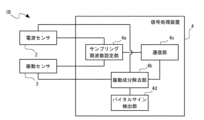
- FIG. 5(a) is a block diagram showing a schematic configuration of a sensor system 1A according to the second embodiment of the present invention.
- the sensor system 1A is different from the sensor system 1 according to the first embodiment in that the signal processing device 4 is provided with a vibration component removing section 4b and a communication section 4c. is similar to the sensor system 1 by
- the vibration component removal unit 4b removes or attenuates the vibration data component as noise detected by the vibration sensor 3 from the reflected wave data received by the radio wave sensor 2.
- the communication unit 4c transmits the extracted body surface displacement data wirelessly or by wire to an external device such as a personal computer or an ECU (Electronic Control Unit) in a vehicle.
- the external device performs predetermined processing using the received body surface displacement data and the like.
- the vibration component removal unit 4b uses blind sound source separation techniques such as independent component analysis (ICA) and independent vector analysis (IVA) to extract the vibration sensor 3 from the reflected wave data input from the radio wave sensor 2. isolate the input vibration data from At this time, the dimension of the reflected wave data is m in the SI unit system, and the dimension of the vibration data is m/ s2 in the SI unit system. After the times integration, independent component analysis and independent vector analysis are performed.
- ICA independent component analysis
- IVA independent vector analysis
- the vibration component removing unit 4b may be an adaptive filter using an algorithm such as LMS (Least Mean Square).
- the adaptive filter can separate the vibration data input from the vibration sensor 3 from the reflected wave data input from the radio wave sensor 2 .
- FIG. 5(b) is a block diagram showing the circuit configuration of the vibration component removing section 4b configured using such an adaptive filter 4b1.
- the noise (vibration data) that is superimposed on the reflected wave data input from the radio wave sensor 2 propagates and superimposes over a distance away from the source, so it is affected by the transmission characteristics in between. Therefore, the vibration component remover 4b obtains the difference between the reflected wave data and the vibration data using the subtractor 4b2, and feeds back the difference from the output of the subtractor 4b2 to the adaptive filter 4b1. Then, by adjusting the magnitude of the transmission coefficient W1 of the adaptive filter 4b1, the vibration data is separated from the reflected wave data, and the body surface displacement and the like are extracted.
- the vibration component removing unit 4b may use Demucs, Sepformer, Conv-TasNet, etc. used for speech separation, or machine learning methods based on modifications thereof. By these techniques, the vibration data input from the vibration sensor 3 can be separated from the reflected wave data input from the radio wave sensor 2 .
- the vibration sensor 3 can be detected from the reflected wave data received by the radio wave sensor 2 with reduced power consumption and without changing the vibration component removal performance. can remove or attenuate components of the vibration data sensed at .
- the sensor system 1A according to the second embodiment can also be applied to a driver monitoring system by appropriately arranging the radio wave sensor 2 and the vibration sensor 3 in the vehicle interior of the vehicle 11 as described with reference to FIG. . In this case, the power consumption can be reduced, and the vehicle 11 provided with the sensor system 1A that does not change the vibration component removal performance can be provided.
- FIG. 6 is a block diagram showing a schematic configuration of a sensor system 1B according to the third embodiment of the invention.
- the sensor system 1B differs from the sensor system 1A according to the second embodiment in that the signal processing device 4 is provided with a vital sign detection unit 4d, and the measurement target 5 is a human body. is the same as the sensor system 1A according to the embodiment.
- the vital sign detection unit 4d detects the vital signs of the human body from the reflected wave data from which the vibration data component has been removed or attenuated by the vibration component removal unit 4b.
- the vital signs are the heart rate, heart rate variability, respiration rate, respiration depth, and the like of the human body that is the object 5 to be measured.
- vital signs are detected from the body surface displacement of the human body, which is measured as a change in the distance from the radio wave sensor 2 to the radio wave irradiation point on the human body.
- the vibration component is removed or attenuated by the vibration component removal unit 4b, and the vibration component is removed or reduced from the reflected wave data without changing the performance of removing the vibration component from the vital signs.
- the vital signs of the human body can be detected.
- the sensor system 1B according to the third embodiment can also be applied to a driver monitoring system by appropriately arranging the radio wave sensor 2 and the vibration sensor 3 in the vehicle interior of the vehicle 11 as described with reference to FIG. . In this case, the power consumption can be reduced, and the vehicle 11 provided with the sensor system 1B that does not change the performance of removing the vibration component from the vital signs can be provided.
- FIG. 7 is a block diagram showing a schematic configuration of a sensor system 1C according to the fourth embodiment of the invention.
- the sensor system 1 ⁇ /b>C differs from the sensor system 1 according to the first embodiment in that the vibration sensor 3 is configured by a vibration sensor built into a wearable device such as a smartwatch or a smartphone 6 . Other points are the same as the sensor system 1 according to the first embodiment.
- the wearable device or smart phone 6 is not limited to these, and may be any mobile device having a communication function with the vibration sensor 3 . In this configuration, communication between the vibration sensor 3 and the signal processing device 4 is performed wirelessly, such as Bluetooth (registered trademark), or wired.
- the radio wave sensor 2 emits a radio wave with a sampling frequency f based on the vibration actually detected using the vibration sensor built into the wearable device or the smartphone 6. become. Therefore, it is possible to provide the sensor system 1C that can reduce the power consumption by suppressing the frequency range of the radio waves emitted from the radio wave sensor 2 while simplifying the configuration of the sensor system 1C to reduce the product price. .
- the vibration sensor 3 is a wearable device such as a smart watch or a smartphone. 6 can be configured by a vibration sensor built in. Also in this case, the same effects as those of the sensor system 1C according to the fourth embodiment are obtained. Also, in the sensor system 1C according to the fourth embodiment, the radio wave sensor 2 and the wearable device or smartphone 6 serving as the vibration sensor 3 are appropriately arranged inside the vehicle 11 as described with reference to FIG. and can be applied to driver monitoring systems. Also in this case, it is possible to provide the vehicle 11 having the sensor system 1C capable of reducing power consumption.
Landscapes
- Engineering & Computer Science (AREA)
- Radar, Positioning & Navigation (AREA)
- Remote Sensing (AREA)
- Physics & Mathematics (AREA)
- Computer Networks & Wireless Communication (AREA)
- General Physics & Mathematics (AREA)
- Electromagnetism (AREA)
- Measurement Of Mechanical Vibrations Or Ultrasonic Waves (AREA)
Priority Applications (4)
| Application Number | Priority Date | Filing Date | Title |
|---|---|---|---|
| DE112022004891.3T DE112022004891T5 (de) | 2021-12-10 | 2022-11-25 | Sensorsystem, fahrzeug mit dem sensorsystem und funkwellen-sende- und -empfangsverfahren |
| CN202280081398.9A CN118355292A (zh) | 2021-12-10 | 2022-11-25 | 传感器系统、具备该传感器系统的车辆以及电波发送接收方法 |
| JP2023566238A JP7658460B2 (ja) | 2021-12-10 | 2022-11-25 | センサシステムおよびそれを備えた車両並びに電波送受信方法 |
| US18/661,709 US20240295630A1 (en) | 2021-12-10 | 2024-05-13 | Sensor system, vehicle comprising said sensor system, and radio wave transmitting and receiving method |
Applications Claiming Priority (2)
| Application Number | Priority Date | Filing Date | Title |
|---|---|---|---|
| JP2021200762 | 2021-12-10 | ||
| JP2021-200762 | 2021-12-10 |
Related Child Applications (1)
| Application Number | Title | Priority Date | Filing Date |
|---|---|---|---|
| US18/661,709 Continuation US20240295630A1 (en) | 2021-12-10 | 2024-05-13 | Sensor system, vehicle comprising said sensor system, and radio wave transmitting and receiving method |
Publications (1)
| Publication Number | Publication Date |
|---|---|
| WO2023106136A1 true WO2023106136A1 (ja) | 2023-06-15 |
Family
ID=86730211
Family Applications (1)
| Application Number | Title | Priority Date | Filing Date |
|---|---|---|---|
| PCT/JP2022/043601 Ceased WO2023106136A1 (ja) | 2021-12-10 | 2022-11-25 | センサシステムおよびそれを備えた車両並びに電波送受信方法 |
Country Status (5)
| Country | Link |
|---|---|
| US (1) | US20240295630A1 (https=) |
| JP (1) | JP7658460B2 (https=) |
| CN (1) | CN118355292A (https=) |
| DE (1) | DE112022004891T5 (https=) |
| WO (1) | WO2023106136A1 (https=) |
Cited By (1)
| Publication number | Priority date | Publication date | Assignee | Title |
|---|---|---|---|---|
| WO2025100208A1 (ja) * | 2023-11-07 | 2025-05-15 | 積水ハウス株式会社 | 生体情報検出システム、生体情報検出方法及び情報記憶媒体 |
Citations (3)
| Publication number | Priority date | Publication date | Assignee | Title |
|---|---|---|---|---|
| JPH06167565A (ja) * | 1992-08-14 | 1994-06-14 | Vorad Safety Syst Inc | デジタル信号処理を用いる多周波数・多目標車両用レーダシステム |
| JP2013539854A (ja) * | 2010-09-13 | 2013-10-28 | オランジュ | 物体を検出するための方法、デバイス、及びシステム |
| US20130328726A1 (en) * | 2012-06-08 | 2013-12-12 | Qualcomm Incorporated | Oscillating mobile device position determination |
Family Cites Families (1)
| Publication number | Priority date | Publication date | Assignee | Title |
|---|---|---|---|---|
| JP2021071326A (ja) | 2019-10-29 | 2021-05-06 | パナソニックIpマネジメント株式会社 | 信号処理システム、及びセンサシステム |
-
2022
- 2022-11-25 WO PCT/JP2022/043601 patent/WO2023106136A1/ja not_active Ceased
- 2022-11-25 CN CN202280081398.9A patent/CN118355292A/zh active Pending
- 2022-11-25 JP JP2023566238A patent/JP7658460B2/ja active Active
- 2022-11-25 DE DE112022004891.3T patent/DE112022004891T5/de active Pending
-
2024
- 2024-05-13 US US18/661,709 patent/US20240295630A1/en active Pending
Patent Citations (3)
| Publication number | Priority date | Publication date | Assignee | Title |
|---|---|---|---|---|
| JPH06167565A (ja) * | 1992-08-14 | 1994-06-14 | Vorad Safety Syst Inc | デジタル信号処理を用いる多周波数・多目標車両用レーダシステム |
| JP2013539854A (ja) * | 2010-09-13 | 2013-10-28 | オランジュ | 物体を検出するための方法、デバイス、及びシステム |
| US20130328726A1 (en) * | 2012-06-08 | 2013-12-12 | Qualcomm Incorporated | Oscillating mobile device position determination |
Cited By (1)
| Publication number | Priority date | Publication date | Assignee | Title |
|---|---|---|---|---|
| WO2025100208A1 (ja) * | 2023-11-07 | 2025-05-15 | 積水ハウス株式会社 | 生体情報検出システム、生体情報検出方法及び情報記憶媒体 |
Also Published As
| Publication number | Publication date |
|---|---|
| JP7658460B2 (ja) | 2025-04-08 |
| CN118355292A (zh) | 2024-07-16 |
| JPWO2023106136A1 (https=) | 2023-06-15 |
| DE112022004891T5 (de) | 2024-08-08 |
| US20240295630A1 (en) | 2024-09-05 |
Similar Documents
| Publication | Publication Date | Title |
|---|---|---|
| US10779427B2 (en) | Method for measuring electromagnetic signal radiated from device and electronic device thereof | |
| EP3852105B1 (en) | Noise reduction method and apparatus for on-board environment, electronic device and storage medium | |
| EP3682651B1 (en) | Low latency audio enhancement | |
| EP3125237A1 (en) | Active noise cancellation apparatus and method for improving voice recognition performance | |
| US20160071526A1 (en) | Acoustic source tracking and selection | |
| KR20200086476A (ko) | 전자기 신호를 측정하기 위한 방법 및 그 전자 장치 | |
| KR102926603B1 (ko) | 음성 인식의 활성화 | |
| CN109346075A (zh) | 通过人体振动识别用户语音以控制电子设备的方法和系统 | |
| US9582121B2 (en) | Signal processing for acoustic user input | |
| EP3493206A2 (en) | Electronic apparatus and control method thereof | |
| CN115071613A (zh) | 车辆控制方法、电子设备及存储介质 | |
| EP2945156A1 (en) | Audio signal recognition method and electronic device supporting the same | |
| JP2021071326A (ja) | 信号処理システム、及びセンサシステム | |
| JP2015506491A (ja) | 音響信号の修正 | |
| JP6367691B2 (ja) | 報知音感知・識別装置、報知音感知・識別方法、報知音感知・識別プログラム | |
| WO2023106136A1 (ja) | センサシステムおよびそれを備えた車両並びに電波送受信方法 | |
| CN112509571A (zh) | 信息处理装置和记录介质 | |
| CN115703388A (zh) | 座椅嵌入式言语传感器 | |
| JP7687442B2 (ja) | センサシステムおよびそれを備えた車両 | |
| CN115331672B (zh) | 设备控制方法、装置、电子设备及存储介质 | |
| JP7831427B2 (ja) | 生体情報取得装置、及び生体情報取得方法 | |
| CN110728990B (zh) | 基音检测方法、装置、终端设备和介质 | |
| CN113160790A (zh) | 回声消除方法、装置、电子设备及存储介质 | |
| CN121768352A (zh) | 路噪主动降噪方法、装置、设备及存储介质 | |
| CN119649804A (zh) | 车内语音助手的控制方法、装置、电子设备及车辆 |
Legal Events
| Date | Code | Title | Description |
|---|---|---|---|
| 121 | Ep: the epo has been informed by wipo that ep was designated in this application |
Ref document number: 22904067 Country of ref document: EP Kind code of ref document: A1 |
|
| ENP | Entry into the national phase |
Ref document number: 2023566238 Country of ref document: JP Kind code of ref document: A |
|
| WWE | Wipo information: entry into national phase |
Ref document number: 202280081398.9 Country of ref document: CN |
|
| WWE | Wipo information: entry into national phase |
Ref document number: 112022004891 Country of ref document: DE |
|
| 122 | Ep: pct application non-entry in european phase |
Ref document number: 22904067 Country of ref document: EP Kind code of ref document: A1 |