WO2023106037A1 - 液圧トランスミッション - Google Patents
液圧トランスミッション Download PDFInfo
- Publication number
- WO2023106037A1 WO2023106037A1 PCT/JP2022/042034 JP2022042034W WO2023106037A1 WO 2023106037 A1 WO2023106037 A1 WO 2023106037A1 JP 2022042034 W JP2022042034 W JP 2022042034W WO 2023106037 A1 WO2023106037 A1 WO 2023106037A1
- Authority
- WO
- WIPO (PCT)
- Prior art keywords
- pressure chamber
- hydraulic
- pressure
- piston
- rod
- Prior art date
- Legal status (The legal status is an assumption and is not a legal conclusion. Google has not performed a legal analysis and makes no representation as to the accuracy of the status listed.)
- Ceased
Links
Images


Classifications
-
- F—MECHANICAL ENGINEERING; LIGHTING; HEATING; WEAPONS; BLASTING
- F15—FLUID-PRESSURE ACTUATORS; HYDRAULICS OR PNEUMATICS IN GENERAL
- F15B—SYSTEMS ACTING BY MEANS OF FLUIDS IN GENERAL; FLUID-PRESSURE ACTUATORS, e.g. SERVOMOTORS; DETAILS OF FLUID-PRESSURE SYSTEMS, NOT OTHERWISE PROVIDED FOR
- F15B11/00—Servomotor systems without provision for follow-up action; Circuits therefor
- F15B11/06—Servomotor systems without provision for follow-up action; Circuits therefor involving features specific to the use of a compressible medium, e.g. air, steam
- F15B11/072—Combined pneumatic-hydraulic systems
- F15B11/076—Combined pneumatic-hydraulic systems with pneumatic drive or displacement and speed control or stopping by hydraulic braking
-
- F—MECHANICAL ENGINEERING; LIGHTING; HEATING; WEAPONS; BLASTING
- F15—FLUID-PRESSURE ACTUATORS; HYDRAULICS OR PNEUMATICS IN GENERAL
- F15B—SYSTEMS ACTING BY MEANS OF FLUIDS IN GENERAL; FLUID-PRESSURE ACTUATORS, e.g. SERVOMOTORS; DETAILS OF FLUID-PRESSURE SYSTEMS, NOT OTHERWISE PROVIDED FOR
- F15B3/00—Intensifiers or fluid-pressure converters, e.g. pressure exchangers; Conveying pressure from one fluid system to another, without contact between the fluids
-
- F—MECHANICAL ENGINEERING; LIGHTING; HEATING; WEAPONS; BLASTING
- F15—FLUID-PRESSURE ACTUATORS; HYDRAULICS OR PNEUMATICS IN GENERAL
- F15B—SYSTEMS ACTING BY MEANS OF FLUIDS IN GENERAL; FLUID-PRESSURE ACTUATORS, e.g. SERVOMOTORS; DETAILS OF FLUID-PRESSURE SYSTEMS, NOT OTHERWISE PROVIDED FOR
- F15B7/00—Systems in which the movement produced is definitely related to the output of a volumetric pump; Telemotors
- F15B7/02—Systems with continuously-operating input and output apparatus
-
- F—MECHANICAL ENGINEERING; LIGHTING; HEATING; WEAPONS; BLASTING
- F15—FLUID-PRESSURE ACTUATORS; HYDRAULICS OR PNEUMATICS IN GENERAL
- F15B—SYSTEMS ACTING BY MEANS OF FLUIDS IN GENERAL; FLUID-PRESSURE ACTUATORS, e.g. SERVOMOTORS; DETAILS OF FLUID-PRESSURE SYSTEMS, NOT OTHERWISE PROVIDED FOR
- F15B7/00—Systems in which the movement produced is definitely related to the output of a volumetric pump; Telemotors
- F15B7/06—Details
- F15B7/10—Compensation of the liquid content in a system
Definitions
- the present invention relates to a hydraulic transmission that drives a hydraulic actuator.
- Non-Patent Documents 1 and 2 As a hydraulic drive method using tap water or the like as a hydraulic fluid, for example, a hydrostatic transmission consisting of a pair of master cylinder and slave cylinder described in Non-Patent Documents 1 and 2 is known. A completely harmless remotely driven robot can be realized by using tap water. When using this in an automatically controlled hydraulically driven robot, the problem is how to configure the master cylinder.
- Non-Patent Documents 1 and 2 use an electric actuator as the master cylinder, but there is a problem that an electric actuator that can generate a large force that can withstand the use of a robot or the like is expensive.
- Patent Literature 1 discloses a method of obtaining high hydraulic pressure by configuring the master cylinder with an air-liquid pressure booster.
- the hydraulic drive device described in Patent Document 1 includes first and second air-liquid pressure boosters for converting air pressure supplied from an air pressure source into hydraulic pressure, a hydraulic actuator having first and second pressure chambers, An operating state acquisition unit that acquires the operating state of the hydraulic actuator, and first and second air pressures provided in the first and second air supply passages that supply air from the air pressure source to the first and second air-liquid pressure boosters, respectively.
- the control device controls the first and second air pressure valves based on the acquisition result of the operating state acquiring section.
- the control device controls the first and second air pressure valves based on the acquisition result of the operating state acquiring section.
- two air-liquid pressure boosters and two pneumatic servo valves are used, there is a problem that not only the size of the driving device increases, but also the cost increases.
- the present invention provides a hydraulic transmission that is smaller and less expensive than conventional ones, and that can easily control various high-load hydraulic actuators, such as hydraulic actuators. It is an object.
- the hydraulic transmission according to claim 1 includes a drive means (drive section 3) driven by fluid pressure (for example, air pressure or hydraulic pressure), a hydraulic actuator (4) driven by the hydraulic fluid supplied from the driving means (driving section 3);
- the driving means (3) is a hollow cylinder chamber (30); a piston (31) reciprocally provided in the cylinder chamber (30); a rod (left rod 32, right rod 33) provided on the piston (31), One end (left end 32a) of the rod (left rod 32) is provided with a first pressure chamber (left pressure chamber 34) filled with liquid (working fluid L1), A second pressure chamber (right pressure chamber 35) filled with liquid (working fluid L2) is provided at the other end (right end 33a) of the rod (right rod 33),
- the piston (31) partitions the inside of the cylinder chamber (30) into a first driving pressure chamber (left driving pressure chamber 36) and a second driving pressure chamber (right driving pressure chamber 37), The area of the ends (left end 31a, right end 31b) of the piston (31) is larger than the area of the ends
- the hydraulic pressure transmission is connected to the hydraulic actuator (4) and the drive means (drive section 3).
- the preload is adjusted according to the state of the hydraulic actuator (4), and the liquids (working fluids L1, L2 ) is provided (for example, a pump 15 and a tank T).
- a hydraulic hydraulic transmission according to claim 3 is the hydraulic transmission (1B) according to claim 1 or 2, wherein the hydraulic actuator (4) and the driving means (driving section 3) are connected to each other.
- the supply paths (first supply path 13, second supply path 14) are characterized by being provided with a hydraulic cylinder (4B) or a rotary pump.
- the hydraulic actuator (4) can be driven only by driving the driving means (driving section 3) using fluid pressure (for example, air pressure or hydraulic pressure).
- the hydraulic actuator (4) can be driven only by the drive means (drive section 3) without preparing the first and second pneumatic-liquid converters as in the prior art.
- the area of the ends (left end 31a, right end 31b) of the piston (31) is made larger than the area of the ends (left end 32a, right end 33a) of the rods (left rod 32, right rod 33).
- various high-load hydraulic actuators can be easily controlled, and the size and cost can be made smaller and cheaper than before.
- the supply passages (first supply passage 13, second supply passage 14) connected to the hydraulic actuator (4) and the drive means (drive section 3) are provided with the hydraulic pressure Since a mechanism is provided to adjust the preload according to the state of the actuator (4) and to supply the liquids (working fluids L1 and L2) that are insufficient due to leakage, the preload can be adjusted simply and easily. Therefore, it is possible to prevent the liquids (working liquids L1 and L2) from becoming negative pressure. Furthermore, the amount of leakage can be compensated.
- the supply paths (first supply path 13, second supply path 14) connected to the hydraulic actuator (4) and the drive means (drive section 3) have a hydraulic pressure
- the presence of a cylinder (4B) or rotary pump facilitates precise control of the hydraulic actuator (4).
- bilateral control and power assist control can be realized by operating the hydraulic cylinder (4B) or the rotary pump with another actuator or human power.
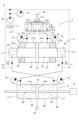
- FIG. 1 is a schematic diagram of a hydraulic transmission according to one embodiment of the present invention
- FIG. FIG. 5 is a schematic diagram of a hydraulic transmission according to another embodiment of the present invention
- FIG. 5 is a schematic diagram of a hydraulic transmission according to another embodiment of the present invention
- FIG. 5 is a schematic diagram of a hydraulic transmission according to another embodiment of the present invention
- the hydraulic transmission in this embodiment is used for underwater work such as fisheries, harbors, rivers, and dams, high-pressure washing, waste disposal, medicines and cosmetics, food processing, sinks such as restaurants, markets, toilets, hospitals and nursing facilities, and agriculture and forestry. , livestock industry, power generation facilities, firefighting equipment, etc.
- the hydraulic transmission 1 is mainly composed of a servo valve 2, a driving section 3, and a hydraulic actuator 4. As shown in FIG. Each configuration will be described in detail below.
- the servo valve 2 is a 3-position, 5-port servo valve. Furthermore, the control port 2c communicates with the second control path 12, and the discharge ports 2d and 2e communicate with the outside.
- the servo valve 2 has a spool driven by a solenoid, and depending on the position of the spool, it is possible to steplessly change the supply/cutoff of the air pressure with good responsiveness. ing. That is, when the spool is positioned on the left side in FIG. 1, the supply port 2a communicates with the first control path 11 and the discharge port 2e communicates with the second control path 12. FIG. As a result, the air pressure supplied from the air pressure source 10 is supplied to the first control path 11 .
- the supply port 2a is communicated with the second control path 12 and the discharge port 2d is communicated with the first control path 11.
- the air pressure supplied from the air pressure source 10 is supplied to the second control path 12 .
- the drive unit 3 includes a hollow cylinder chamber 30, a piston 31 reciprocally provided in the cylinder chamber 30, a left rod 32 provided at a left end portion 31a of the piston 31, a piston and a right rod 33 provided at the right end portion 31b of 31 .
- a left pressure chamber 34 in which the left rod 32 can freely move is provided on the left end portion 32a side of the left rod 32.
- the left pressure chamber 34 contains water. Hydraulic fluid L1 such as is enclosed.
- a right pressure chamber 35 in which the right rod 33 can freely move is provided on the right end portion 33a side of the right rod 33.
- the right pressure chamber 35 contains water. Hydraulic fluid L2 such as is enclosed.
- the first supply passage 13 connected to the hydraulic actuator 4 is connected to the left pressure chamber 34, and the hydraulic actuator 4 is connected to the right pressure chamber 35.
- a second supply path 14 is connected.
- the inside of the cylinder chamber 30 is divided into a left driving pressure chamber 36 and a right driving pressure chamber 37 by the piston 31.
- the left driving pressure chamber 36 is connected to the first control path 11.
- a second control path 12 is connected to the right drive pressure chamber 37 .
- the left drive pressure chamber 36 and the right drive pressure chamber 37 are filled with air, and as shown in FIG.
- the right rod 33 is arranged and fixed to 37 as shown in FIG.
- the pressure increase ratio of the hydraulic fluid L1 is expressed by the area of the left end portion 31a of the piston 31/the area of the left end portion 32a of the left rod 32
- the pressure increase ratio of the hydraulic fluid L2 is expressed by the right end portion of the piston 31.
- the area of the right end portion 33a of the right rod 33 is represented by the area of 31b. Therefore, unless the relationship of the area of the left end portion 31a of the piston 31>the area of the left end portion 32a of the left rod 32, the area of the right end portion 31b of the piston 31>the area of the right end portion 33a of the right rod 33, the hydraulic fluid L1 , L2 are not boosted.
- the hydraulic fluid L3 such as water stored in the tank T is discharged at a constant pressure (for example, pressure P 0 ) by the pump 15, and the check valve 16 is added to the first supply line 13 via the , and is added to the second supply line 14 via the check valve 17 .
- This can prevent the hydraulic fluids L1 and L2 from becoming negative pressure. That is, when the right rod 33 enters the right pressure chamber 35 and the hydraulic fluid L2 sealed in the right pressure chamber 35 is supplied to the hydraulic actuator 4 through the second supply passage 14, the vacuum effect , the hydraulic fluid L1 in the left pressure chamber 34 tends to have a negative pressure.
- a constant pressure (for example, pressure P 0 ) is applied to the first supply path 13 and the second supply path 14 as preload.
- the pressure of the hydraulic fluid L1 flowing through the first supply passage 13 fluctuates, and the pressure of the hydraulic fluid L2 flowing through the second supply passage 14 fluctuates with respect to this constant pressure (for example, the pressure P 0 ). It will happen. Therefore, by applying this constant pressure (for example, pressure P 0 ), it is possible to prevent the hydraulic fluids L1 and L2 from becoming negative pressure. Thus, by doing so, it is possible to easily adjust the preload, thereby preventing the hydraulic fluids L1 and L2 from becoming negative pressure.
- the check valve 16 prevents the hydraulic fluid L1 flowing through the first supply passage 13 from flowing to the pump 15 side
- the check valve 17 prevents the hydraulic fluid L2 flowing through the second supply passage 14 from flowing toward the pump 15 side. It is intended to prevent
- the hydraulic actuator 4 includes a hollow cylinder chamber 40, a piston 41 reciprocally provided in the cylinder chamber 40, a left rod 42 provided at a left end portion 41a of the piston 41, and a right rod 43 provided at the right end portion 41 b of the piston 41 .
- the cylinder chamber 40 is partitioned into a left pressure chamber 44 and a right pressure chamber 45 by the piston 41.
- the left pressure chamber 44 is connected to the second supply passage 14, A first supply path 13 is connected to the pressure chamber 45 .
- the left pressure chamber 44 is filled with a hydraulic fluid L4 such as water
- the right pressure chamber 45 is filled with a hydraulic fluid L5 such as water.
- the left pressure chamber 44 has the left rod 42 fixed therein
- the right pressure chamber 45 has the right rod 43 fixed therein, as shown in FIG.
- a second pressure sensor P2 is connected to the second control path 12 to detect the pressure of the air pressure flowing through the second control path 12 .
- a fourth pressure sensor Pb is connected to the first supply path 13 to detect the pressure of the hydraulic fluid flowing through the first supply path 13, and the second supply path 14 is connected to the second supply path.
- a third pressure sensor P a is connected to detect the pressure of the hydraulic fluid flowing through the passage 14 .
- a fifth pressure sensor P0 is connected to the discharge side of the pump 15 to detect the pressure of the discharged hydraulic fluid L3.
- the hydraulic actuator 4 is provided with a position detection sensor 18 that detects the position of the piston 41 .
- the servo valve 2 is controlled, the supply port 2 a and the first control path 11 are communicated, and air pressure is supplied from the air pressure source 10 to the first control path 11 .
- the piston 31 moves rightward in FIG. 1, and the right rod 33 accordingly moves rightward in FIG.
- the right rod 33 enters the right pressure chamber 35, thereby pushing out the hydraulic fluid L2 enclosed in the right pressure chamber 35 and supplying it to the left pressure chamber 44 through the second supply passage 14. be done.
- the hydraulic fluid L2 is supplied from the second supply passage 14 to the left pressure chamber 44, the amount of the hydraulic fluid L4 sealed in the left pressure chamber 44 is increased. Move to the right as indicated. Accordingly, the right rod 43 and the left rod 42 move rightward in FIG.
- the servo valve 2 is controlled, the supply port 2a and the second control path 12 are communicated, and air pressure is supplied from the air pressure source 10 to the second control path 12.
- the piston 31 moves leftward in FIG. 1, and the left rod 32 accordingly moves leftward in FIG.
- the left rod 32 enters the left pressure chamber 34, thereby pushing out the hydraulic fluid L1 enclosed in the left pressure chamber 34 and supplying it to the right pressure chamber 45 through the first supply passage 13. be done.
- the hydraulic fluid L1 is supplied from the first supply passage 13 to the right pressure chamber 45, the amount of the hydraulic fluid L5 sealed in the right pressure chamber 45 is increased. to the left as indicated.
- control unit (not shown). Specifically, first, arbitrary target values (or trajectories) are set for the position, velocity, and force of the piston 41 of the hydraulic actuator 4 by the user or a higher-level controller. Control is performed so that the error between the target value and the actual value or estimated value detected by the sensors (position detection sensor 18, third pressure sensor P a , fourth pressure sensor P b ) is small. A section (not shown) controls the servo valve 2 and feedback-controls the drive section 3 . At this time, the control unit (not shown) operates the fifth pressure sensor P 0 so that a constant pressure (for example, pressure P 0 ) is applied to the first supply path 13 and the second supply path 14 as preload. I am watching.
- a constant pressure for example, pressure P 0
- Each estimated value is calculated by a control unit (not shown).
- force estimation The thrust of the piston 41 is calculated by multiplying the pressure difference by the pressure receiving area of the piston 41 .
- the pressure difference is the value detected by the third pressure sensor P a ⁇ the value detected by the fourth pressure sensor P b , and can be positive or negative.
- This calculation is based on the differential pressure of the air pressure sensor (that is, the detected value detected by the first pressure sensor P1 - the detected value detected by the second pressure sensor P2 ) and the pressure increase ratio (the above-described piston 31 divided by the area of the left end 32a of the left rod 32). In that case, the third pressure sensor P a and the fourth pressure sensor P b are unnecessary.
- position estimation will be described.
- the drive unit 3 may be provided with a position detection sensor 19 for detecting the position of the piston 31, as shown in FIG. Thereby, the position of the piston 41 can be estimated by detecting the position of the piston 31 . In this way, the position and force of the hydraulic actuator 4 can be remotely controlled without attaching a separate sensor to the hydraulic actuator 4 and without using the third pressure sensor P a and the fourth pressure sensor P b . It will be possible.
- hydraulic fluids L1 to L5 are denoted by different reference numerals, but they are all the same hydraulic fluid.
- the hydraulic actuator 4 can be driven only by driving the driving portion 3 using air pressure.
- the hydraulic actuator 4 can be driven only by the drive section 3 without preparing a liquid converter.
- the hydraulic fluid supplied to the hydraulic actuator 4 is increased.
- L1 and L2 can be boosted.
- the leakage amount is compensated as follows.
- a magnetic sensor is arranged on the piston 41 of the hydraulic actuator 4 so that the corresponding relationship can be found, and the switch is set to be turned on at a certain reference position.
- the positional relationship between the drive unit 3 and the piston 31 (left side, right side, etc.) can be known. Therefore, the hydraulic fluid L3 such as water stored in the tank T is temporarily pumped by the pump 15 so that the piston 41 of the hydraulic actuator 4 returns to the desired position (to the right if leftward, and to the left if rightward).
- the higher the differential pressure the larger the supply amount. This makes it possible to compensate for the amount of leakage. If a sensor capable of continuously acquiring the position of the hydraulic actuator 4 on the side of the piston 41 is available, such leakage compensation can be realized more easily.
- the first supply path 13 is connected to the right pressure chamber 45, and the second supply path 14 is connected to the right pressure chamber 45. is connected to the left pressure chamber 44 , but the first supply passage 13 may be connected to the left pressure chamber 44 and the second supply passage 14 may be connected to the right pressure chamber 45 .
- the present invention is not limited to this.
- the left driving pressure chamber 36 and the right driving pressure chamber 37 may be filled with oil instead of air, and hydraulic servo valves may be used instead of the pneumatic servo valves 2 .
- the pump 15 and the tank T are merely examples, and may be driven by a hand pump, an electric pump, an air-hydro converter, an air-hydro booster, or the like.
- check valves 16 and 17 are provided, but they are not essential and may be provided as necessary.
- a hydraulic transmission 1A shown in FIG. 3 has the same configuration except that the servo valve 2 shown in FIG. . It should be noted that the type of pump to be employed is not limited to this.
- Both rotary pumps 2A are fluid pressure pumps, and as shown in FIG. 3, can be rotated in the direction of arrow Y1 (horizontal direction in the drawing) by a servomotor SM. More specifically, when the servomotor SM is rotated leftward in the figure using a control unit (not shown), the fluid is pressure-fed to the first control path 11 . At this time, since the left drive pressure chamber 36 is filled with the fluid, the piston 31 moves rightward in FIG. 3, and accordingly the right rod 33 moves rightward in FIG. As a result, the right rod 33 enters the right pressure chamber 35, and the hydraulic fluid L2 enclosed in the right pressure chamber 35 is pressure-fed to the hydraulic actuator 4 through the second supply passage 14. becomes. As the piston 31 moves rightward in FIG. 3, the fluid filling the right drive pressure chamber 37 is discharged to the second control path 12 . As a result, the fluid passes through the second control path 12 and is discharged to both rotary pumps 2A.
- the fluid is pressure-fed to the second control path 12 .
- the piston 31 moves leftward in FIG. 2, and the left rod 32 moves leftward in FIG.
- the left rod 32 enters the left pressure chamber 34, thereby pushing out the hydraulic fluid L1 sealed in the left pressure chamber 34, passing through the first supply passage 13, and pumping it to the hydraulic actuator 4. It will be done.
- the fluid filling the left driving pressure chamber 36 is discharged to the first control path 11 .
- the fluid passes through the first control path 11 and is discharged to both rotary pumps 2A.
- the hydraulic actuator 4 can be driven only by driving the driving portion 3 using the fluid, and the conventional first and second pneumatic-liquid converters can be used. It is possible to drive the hydraulic actuator 4 only by the driving section 3 without any preparation. Furthermore, by making the area of the left end portion 31a and the right end portion 31b of the piston 31 larger than the area of the left end portion 32a and the right end portion 33a of the left rod 32 and the right rod 33, the hydraulic fluid supplied to the hydraulic actuator 4 is increased. L1 and L2 can be boosted. Therefore, even in this way, various high-load hydraulic actuators can be easily controlled, and the size and cost can be made smaller and cheaper than before. Further, when liquid is used as the fluid, if the dual rotary pump 2A is used, the liquid is circulated as described above, so a tank for storing the liquid is unnecessary.
- the hydraulic transmission 1B shown in FIG. 4 only has a small hydraulic cylinder 4B newly provided between the first supply passage 13 and the second supply passage 14, and the rest of the configuration is similar to that shown in FIG. 1 has the same configuration as the hydraulic transmission 1 shown in FIG. Therefore, the same reference numerals are given to the other configurations, and description thereof is omitted.
- the small hydraulic cylinder 4B includes a hollow cylinder chamber 40B, a piston 41B reciprocatingly provided in the cylinder chamber 40B, and a rod 42B provided in the piston 41B. have.
- the inside of the cylinder chamber 40B is divided into a left fluid chamber 43B and a right fluid chamber 44B by a piston 41B.
- the left fluid chamber 43B is filled with hydraulic fluid L6B such as water.
- a hydraulic fluid L7B such as water is enclosed.
- the left fluid chamber 43B is connected to the left pressure chamber 44 of the hydraulic actuator 4 via the second supply path 14, and the right fluid chamber 44B is connected to the hydraulic actuator 4 via the first supply path 13. is connected to the right pressure chamber 45 of the .
- FIG. 4 shows a modification of the hydraulic transmission 1 shown in FIG. 1, but it is also applicable to the hydraulic transmission 1 shown in FIG. 2 and the hydraulic transmission 1A shown in FIG. Moreover, although FIG. 4 shows an example in which a small hydraulic cylinder 4B is provided, it may be changed to a small rotary motor instead.
- 1, 1A, 1B hydraulic transmission 3 driving unit (driving means) 15 pump (mechanism) 30 cylinder chamber 31 piston 31a left end (end) 31b right end (end) 32 left rod (rod) 32a left end (one end, end) 33 right rod (rod) 33a right end (other end, end) 34 left pressure chamber (first pressure chamber) 35 right pressure chamber (second pressure chamber) 36 left drive pressure chamber (first drive pressure chamber) 37 right drive pressure chamber (second drive pressure chamber) 4 hydraulic actuator 40 cylinder chamber 41 piston 42 left rod 43 right rod 44 left pressure chamber 45 right pressure chamber 13 first supply path (supply path) 14 second supply channel (supply channel) 4B Hydraulic cylinders 16, 17 Check valves L1, L2, L4, L5 Hydraulic fluid (liquid) T tank (mechanism)
Landscapes
- Engineering & Computer Science (AREA)
- Physics & Mathematics (AREA)
- Fluid Mechanics (AREA)
- Mechanical Engineering (AREA)
- General Engineering & Computer Science (AREA)
- Fluid-Pressure Circuits (AREA)
- Actuator (AREA)
Priority Applications (1)
| Application Number | Priority Date | Filing Date | Title |
|---|---|---|---|
| JP2023566183A JP7725094B2 (ja) | 2021-12-10 | 2022-11-11 | 液圧トランスミッション |
Applications Claiming Priority (2)
| Application Number | Priority Date | Filing Date | Title |
|---|---|---|---|
| JP2021-200869 | 2021-12-10 | ||
| JP2021200869 | 2021-12-10 |
Publications (1)
| Publication Number | Publication Date |
|---|---|
| WO2023106037A1 true WO2023106037A1 (ja) | 2023-06-15 |
Family
ID=86730386
Family Applications (1)
| Application Number | Title | Priority Date | Filing Date |
|---|---|---|---|
| PCT/JP2022/042034 Ceased WO2023106037A1 (ja) | 2021-12-10 | 2022-11-11 | 液圧トランスミッション |
Country Status (2)
| Country | Link |
|---|---|
| JP (1) | JP7725094B2 (https=) |
| WO (1) | WO2023106037A1 (https=) |
Citations (1)
| Publication number | Priority date | Publication date | Assignee | Title |
|---|---|---|---|---|
| JPS6241905U (https=) * | 1985-09-02 | 1987-03-13 |
-
2022
- 2022-11-11 JP JP2023566183A patent/JP7725094B2/ja active Active
- 2022-11-11 WO PCT/JP2022/042034 patent/WO2023106037A1/ja not_active Ceased
Patent Citations (1)
| Publication number | Priority date | Publication date | Assignee | Title |
|---|---|---|---|---|
| JPS6241905U (https=) * | 1985-09-02 | 1987-03-13 |
Also Published As
| Publication number | Publication date |
|---|---|
| JPWO2023106037A1 (https=) | 2023-06-15 |
| JP7725094B2 (ja) | 2025-08-19 |
Similar Documents
| Publication | Publication Date | Title |
|---|---|---|
| US20130333366A1 (en) | Hydraulic device for actuating a clutch | |
| US4659294A (en) | Hydrualic pressure amplifier | |
| US10184540B2 (en) | Liquid pressure device | |
| US11085466B2 (en) | Electrohydraulic system for use under water, comprising an electrohydraulic actuator | |
| EP1167778B1 (en) | Rotary servo valve and punch press hydraulic servo device using the rotary servo valve | |
| US10920796B2 (en) | Hydraulic pressure intensifier | |
| JP4786638B2 (ja) | インナースコーピング油圧装置 | |
| US20110073203A1 (en) | Flow channel switching device | |
| US6817067B2 (en) | Tandem electrohydrostatic actuator | |
| WO2023106037A1 (ja) | 液圧トランスミッション | |
| KR20060117577A (ko) | 전기-유압 일체제어형 하이브리드 액추에이터 시스템 | |
| US20230182808A1 (en) | Hydraulic steering system and traveling crane | |
| JP7195557B2 (ja) | 液圧駆動装置 | |
| US9897228B2 (en) | Valve having opposing right-angle actuators | |
| CN116006543A (zh) | 数字液压缸 | |
| JP4965762B2 (ja) | 液圧多重駆動装置およびゲート制御装置並びに翼状体制御装置 | |
| KR101123040B1 (ko) | 유압 편로드 실린더를 구비한 산업용 전기유압 일체형 구동기 시스템 | |
| US9915368B2 (en) | Electrohydraulic valve having dual-action right-angle pilot actuator | |
| CN115929719B (zh) | 数字大流量直接机械反馈式双级电液方向阀 | |
| KR20220012880A (ko) | 모듈 로봇 | |
| CN108351041B (zh) | 多功能卫生阀及其操作方法 | |
| KR102941468B1 (ko) | 액추에이터 제어 장치 | |
| IT202200023787A1 (it) | Apparato di sterzatura con valvola di sterzatura | |
| CN219606196U (zh) | 用于手动阀的控制系统 | |
| JP2006063804A (ja) | 液体供給装置 |
Legal Events
| Date | Code | Title | Description |
|---|---|---|---|
| 121 | Ep: the epo has been informed by wipo that ep was designated in this application |
Ref document number: 22903968 Country of ref document: EP Kind code of ref document: A1 |
|
| ENP | Entry into the national phase |
Ref document number: 2023566183 Country of ref document: JP Kind code of ref document: A |
|
| NENP | Non-entry into the national phase |
Ref country code: DE |
|
| 122 | Ep: pct application non-entry in european phase |
Ref document number: 22903968 Country of ref document: EP Kind code of ref document: A1 |