WO2023105880A1 - ロボットハンド - Google Patents
ロボットハンド Download PDFInfo
- Publication number
- WO2023105880A1 WO2023105880A1 PCT/JP2022/034771 JP2022034771W WO2023105880A1 WO 2023105880 A1 WO2023105880 A1 WO 2023105880A1 JP 2022034771 W JP2022034771 W JP 2022034771W WO 2023105880 A1 WO2023105880 A1 WO 2023105880A1
- Authority
- WO
- WIPO (PCT)
- Prior art keywords
- strain sensor
- flexible finger
- robot hand
- finger
- flexible
- Prior art date
- Legal status (The legal status is an assumption and is not a legal conclusion. Google has not performed a legal analysis and makes no representation as to the accuracy of the status listed.)
- Ceased
Links
Images










Classifications
-
- B—PERFORMING OPERATIONS; TRANSPORTING
- B25—HAND TOOLS; PORTABLE POWER-DRIVEN TOOLS; MANIPULATORS
- B25J—MANIPULATORS; CHAMBERS PROVIDED WITH MANIPULATION DEVICES
- B25J15/00—Gripping heads and other end effectors
- B25J15/08—Gripping heads and other end effectors having finger members
-
- B—PERFORMING OPERATIONS; TRANSPORTING
- B25—HAND TOOLS; PORTABLE POWER-DRIVEN TOOLS; MANIPULATORS
- B25J—MANIPULATORS; CHAMBERS PROVIDED WITH MANIPULATION DEVICES
- B25J15/00—Gripping heads and other end effectors
- B25J15/08—Gripping heads and other end effectors having finger members
- B25J15/12—Gripping heads and other end effectors having finger members with flexible finger members
Definitions
- the present invention relates to a robot hand that transports objects to be transported.
- Patent Document 1 describes a robot gripper control system.
- An object of the present invention is to provide a robot hand capable of transporting a fragile object to be transported without damaging it and transporting the object to be transported at high speed.
- a robot hand includes: a flexible finger configured by an elastic body for carrying an object to be carried; a strain sensor having flexibility, attached to the flexible finger, and detecting deformation of the flexible finger; It has
- a robot hand can transport a fragile object to be transported without damaging it, and can transport the object to be transported at high speed.
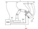
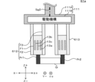
- FIG. 1 is a diagram showing a robot hand 1 according to the first embodiment.
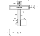
- FIG. 2 is a diagram showing the hand section 11 of the robot hand 1.
- FIG. 3 is a diagram showing the hand part 11 gripping the object to be transported Gr.
- FIG. 4 is a diagram showing a hand portion 11a included in a robot hand 1a according to a modification of the first embodiment.
- FIG. 5 is a diagram showing the hand section 21 provided in the robot hand 2 according to the second embodiment.
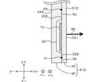
- FIG. 6 is an enlarged view of the first flexible finger 212 of the hand portion 21.
- FIG. 7 is a diagram showing the hand section 31 provided in the robot hand 3 according to the third embodiment.
- FIG. 8 is a diagram showing the hand section 41 provided in the robot hand 4 according to the fourth embodiment.
- FIG. 9 is a diagram showing the first flexible finger 412 of the hand portion 41.
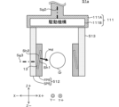
- FIG. 10 is a diagram showing a hand portion 51 included in the robot hand 5 according to the fifth embodiment.
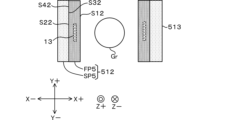
- FIG. 11 is a diagram of the first flexible finger 512 and the second flexible finger 513 viewed in the negative direction of the Z-axis.
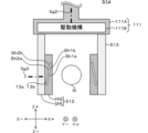
- FIG. 12 is a diagram showing a hand portion 51a according to Modified Example 1 of the hand portion 51.
- FIG. FIG. 13 is a diagram showing a hand portion 51b according to Modified Example 2 of the hand portion 51.
- FIG. 14 is a diagram showing a hand portion 51c according to Modified Example 3 of the hand portion 51.
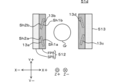
- FIG. 15 is a diagram showing a hand portion 51d according to Modified Example 4 of the hand portion 51.
- FIG. 16 is a diagram of the first flexible finger 512 and the second flexible finger 513 of the hand portion 51d viewed in the negative direction of the Z axis.
- FIG. 17 is a diagram showing a hand portion 51e according to Modified Example 5 of the hand portion 51.
- FIG. 18 is a diagram showing a hand portion 51f according to Modified Example 6 of the hand portion 51.
- FIG. 19 is a diagram showing a recess Hf2 provided in the second member SP5 of the hand portion 51e.
- FIG. 20 is a diagram showing the recess Hf3 provided in the second member SP5 of the hand portion 51e.
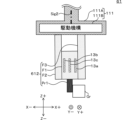
- FIG. 21 is a diagram showing a hand portion 61 provided in the robot hand 6 according to the sixth embodiment.
- FIG. 22 is a diagram of the first soft finger 612 viewed in the positive direction of the Z-axis.
- FIG. 23 is a diagram showing a hand portion 61a according to Modification Example 1 of the hand portion 61. As shown in FIG.
- FIG. 1 is a diagram showing a robot hand 1 according to the first embodiment.
- FIG. 2 is a diagram showing the hand section 11 of the robot hand 1.
- FIG. 3 is a diagram showing the hand part 11 gripping the object to be transported Gr.
- the transport object Gr is an object transported by the robot hand 1 .
- the object to be transported Gr is, for example, an object such as food, or an object such as a precision part that is easily damaged when receiving a strong force.
- the directions are defined as shown in Fig. 2 in order to make the explanation easier to understand.
- the direction in which the first flexible finger 112 and the second flexible finger 113 are arranged is defined as the X-axis direction.
- the direction in which the first flexible finger 112 and the second flexible finger 113 are arranged in the order of the first flexible finger 112 and the second flexible finger 113 is defined as the positive direction of the X axis.
- the direction in which the first flexible finger 112 and the second flexible finger 113 are arranged in the order of the second flexible finger 113 and the first flexible finger 112 is defined as the negative direction of the X axis.
- the direction in which the first flexible finger 112 and the second flexible finger 113 extend is defined as the Z-axis direction.
- a direction orthogonal to the X-axis direction and the Z-axis direction is defined as the Y-axis direction.
- the X-axis direction, Y-axis direction, and Z-axis direction are defined for convenience of explanation. Therefore, the X-axis direction, Y-axis direction, and Z-axis direction do not have to match the X-axis direction, Y-axis direction, and Z-axis direction when the robot hand 1 is actually used.
- the robot hand 1 in this embodiment carries the object Gr to be carried, as shown in FIGS.
- the robot hand 1 includes an arm section 10 , a hand section 11 , a control section 12 and a strain sensor 13 .
- the control unit 12 controls the arm unit 10 and the hand unit 11 so that the robot hand 1 conveys the object to be conveyed Gr. A detailed description will be given below.
- the arm section 10 has multiple arms and multiple joints. Each of the multiple joints rotates on three axes. Thereby, the robot hand 1 adjusts the positional relationship between the robot hand 1 and the object to be transported Gr.
- the hand section 11 includes a driving section 111, a first flexible finger 112, and a second flexible finger 113, as shown in FIG.
- the hand section 11 has a plurality of flexible fingers. Therefore, in this embodiment, the robot hand 1 has a plurality of flexible fingers.
- the drive unit 111 drives each of the flexible fingers.
- the drive section 111 has a housing 111A and a drive mechanism 111B.
- the housing 111A surrounds the driving mechanism 111B.
- the housing 111A protects the drive mechanism 111B from external shocks and the like.
- the material of the housing 111A is, for example, metal (such as steel or aluminum).
- the drive mechanism 111B drives each of the flexible fingers. That is, in this embodiment, the drive mechanism 111B drives the first flexible finger 112 and the second flexible finger 113, respectively. Specifically, the drive mechanism 111B holds a first flexible finger 112 and a second flexible finger 113. As shown in FIG. The drive mechanism 111B moves the first flexible finger 112 and the second flexible finger 113, for example, in the X-axis direction.
- the drive mechanism 111B includes, for example, a motor, gears and racks.
- the rack is, for example, a member having teeth arranged at equal intervals in the X-axis direction. In this case, the motor and gear are coupled. The motor rotates around the Z-axis direction.
- the gear rotates around the Z-axis direction.
- the gear and the rack are in mesh. This causes the rack to move in the X-axis direction when the gear rotates.
- the rack and the first soft finger 112 are connected. Therefore, as the rack moves in the X-axis direction, the first flexible finger 112 moves in the X-axis direction.
- the rack and the second soft finger 113 are connected. Therefore, as the rack moves in the X-axis direction, the second flexible finger 113 moves in the X-axis direction. That is, the distance between the first flexible finger 112 and the second flexible finger 113 changes. For example, as shown in FIG.
- the drive mechanism 111B moves the first flexible finger 112 along the X axis. move in the positive direction. As a result, the first soft finger 112 comes into contact with the transport object Gr (see FIG. 3).
- the drive mechanism 111B moves the second flexible finger 113 in the negative direction of the X axis. As a result, the second flexible finger 113 comes into contact with the transport object Gr (see FIG. 3). That is, the first flexible fingers 112 and the second flexible fingers 113 grip the object Gr as the first flexible fingers 112 and the second flexible fingers 113 contact the object Gr.
- the object to be transported Gr is the object to be grasped.
- a plurality of flexible fingers grip a gripping object.
- the direction in which the drive unit 111 and the first flexible finger 112 are arranged in the order of the first flexible finger 112 and the drive unit 111 is defined as the positive direction of the Z axis.
- the direction in which the drive unit 111 and the first flexible finger 112 are arranged in the order of the drive unit 111 and the first flexible finger 112 is defined as the negative direction of the Z-axis.
- the first flexible finger 112 and the second flexible finger 113 have plate-like bodies extending in the Z-axis direction, for example.
- the first flexible finger 112 has a plate-like body having a first main surface S1 and a second main surface S2.
- the first main surface S1 and the second main surface S2 are the surfaces having the largest areas of the surfaces of the first flexible finger 112 .
- the first main surface S1 and the second main surface S2 are arranged in the order of the second main surface S2 and the first main surface S1 along the positive direction of the X-axis.
- the first main surface S1 faces the transport object Gr.
- the first main surface S1 and the object to be transported Gr come into contact with each other.
- the first soft finger 112 is thin in the X-axis direction, it bends in the negative direction of the X-axis.
- the first flexible finger 112 has a shape elongated in the Y-axis direction and the Z-axis direction, it deforms in a direction perpendicular to the first main surface S1 and the second main surface S2 (the Y-axis direction shown in FIGS. 2 and 3). hard to do.
- the first soft finger 112 does not necessarily have to be a plate-like body.
- the first flexible finger 112 may have, for example, a polygonal prism shape.
- the first flexible finger 112 and the second flexible finger 113 are made of an elastic body made of polymer material.
- the plurality of soft fingers are made of elastic bodies made of polymer material.
- Polymer materials are, for example, epoxy resins or elastomer resins. Therefore, the first flexible finger 112 and the second flexible finger 113 are elastically deformed.
- the first flexible finger 112 and the second flexible finger 113 may be made of a material other than a polymeric material.
- the first flexible finger 112 and the second flexible finger 113 may be metal such as aluminum, for example.
- the control unit 12 controls the arm unit 10 and the hand unit 11.
- the control unit 12 generates, for example, a signal for controlling the arm unit 10 (hereinafter referred to as first control signal) and a signal for controlling the hand unit 11 (hereinafter referred to as second control signal).
- the control unit 12 includes a CPU (Central Processing Unit), a ROM, a RAM, a communication interface, etc. (not shown).
- the CPU of the control unit 12 performs generation processing of the first control signal and the second control signal by reading the program stored in the ROM into the RAM.
- the control section 12 controls the arm section 10 by transmitting the first control signal to the arm section 10 .
- the control section 12 is connected to the arm section 10 via a signal line Sig1.
- the control unit 12 transmits the first control signal to the arm unit 10 via the signal line Sig1.
- the control unit 12 transmits to the arm unit 10 a first control signal for rotating each of the joints.
- Each of the multiple joints rotates based on the first control signal.
- the robot hand 1 adjusts the positional relationship between the robot hand 1 and the object to be transported Gr.
- the control unit 12 controls the hand unit 11 by transmitting the second control signal to the hand unit 11 .
- the control section 12 is connected to the hand section 11 via a signal line Sig2.
- the control unit 12 transmits the second control signal to the hand unit 11 via the signal line Sig2.
- the control unit 12 transmits to the hand unit 11, for example, a second control signal for driving the motor of the driving mechanism 111B.
- the driving mechanism 111B moves each of the first flexible finger 112 and the second flexible finger 113 in the X-axis direction based on the second control signal.
- control unit 12 and the arm unit 10 do not necessarily have to be connected via the signal line Sig1.
- the control unit 12 and the arm unit 10 may be connected by wireless such as a wireless LAN, for example.
- the control unit 12 and the hand unit 11 may be connected by radio such as a wireless LAN.
- the robot hand 1 since the robot hand 1 according to the present embodiment includes the strain sensor 13, even if the object to be transported Gr is easily damaged, the object to be transported Gr can be transported without being damaged. And, the object to be transported Gr can be transported at high speed. A detailed description will be given below.
- the strain sensor 13 detects deformation of at least one flexible finger among the plurality of flexible fingers. Specifically, the strain sensor 13 is attached to at least one flexible finger among the plurality of flexible fingers. Then, deformation of at least one flexible finger among the plurality of flexible fingers is detected.
- strain sensor 13 is attached to first flexible finger 112 .
- the strain sensor 13 is attached to the second main surface S2.
- the strain sensor 13 has a thin plate shape. A main surface of the strain sensor 13 is attached to the second main surface S2. That is, the main surface of the strain sensor 13 and the second main surface S2 are in contact with each other.
- the strain sensor 13 is attached to the end of the first flexible finger 112 in the negative direction of the Z axis.
- the strain sensor 13 need not be attached to the end of the first soft finger 112 in the negative direction of the Z axis.
- the strain sensor 13 may be attached to the end of the first soft finger 112 in the positive direction of the Z axis.
- the first soft finger 112 bends in the negative direction of the X-axis. Therefore, the first main surface S1 of the first flexible finger 112 expands along the Z-axis direction, and the second main surface S2 contracts along the Z-axis direction. As a result, the main surface of the strain sensor 13 contracts as the first soft finger 112 bends and deforms.
- the mounting position of the strain sensor 13 is not limited to this example.
- the strain sensor 13 may be attached to the first main surface S1. In this case, the main surface of the strain sensor 13 shrinks as the first soft finger 112 bends and deforms.
- the strain sensor 13 has flexibility. Therefore, the strain sensor 13 deforms as the first flexible finger 112 deforms. That is, when the second main surface S2 contracts, the main surface of the strain sensor 13 also contracts.
- the strain sensor 13 has an output corresponding to contraction of the main surface of the strain sensor 13 .
- the strain sensor 13 is, for example, either a strain gauge or a piezoelectric sensor.
- the piezoelectric sensor When the strain sensor 13 is a piezoelectric sensor, the piezoelectric sensor generates an electric charge according to the displacement speed of the second main surface S2. Specifically, the piezoelectric sensor generates an electric charge corresponding to the differential value of the displacement amount of the second main surface S2.
- the piezoelectric sensor has a charge amplifier.
- a piezoelectric sensor converts an electric charge into a voltage signal (hereinafter referred to as a first signal) by a charge amplifier.
- the first signal is proportional to the displacement speed of the second main surface S2.
- the piezoelectric sensor can estimate the amount of contraction of the second main surface S2 (that is, the amount of bending deformation of the first flexible finger 112) by integrating the value of the first signal.
- a piezoelectric sensor contains a piezoelectric film.
- the piezoelectric film is, for example, polylactic acid (PLA) or polyvinylidene fluoride (PVDF).
- PLA polylactic acid
- PVDF polyvinylidene fluoride
- the strain sensor 13 is a piezoelectric sensor
- the piezoelectric sensor contains polylactic acid or PVDF.
- Piezoelectricity is generated in polylactic acid by orientation treatment of molecules by stretching.
- the piezoelectric film is polylactic acid
- the piezoelectric film is attached to the first flexible finger 112 such that the stretching direction forms an angle of 45 degrees with respect to the Z-axis direction.
- the piezoelectric film is polyvinylidene fluoride
- the piezoelectric film (the piezoelectric film having the piezoelectric tensor d33) that generates electric charges according to deformation in the plane direction is attached to the second main surface S2.
- the strain gauge detects the amount of deformation of the second main surface S2 (the position of the second main surface S2).
- the strain gauge is attached to the second main surface S2 so that the resistance value decreases according to the amount of contraction of the second main surface S2.
- the piezoelectric sensor outputs detection results based on the displacement speed. Therefore, the piezoelectric sensor can detect, with high sensitivity, the displacement of the measurement object (first flexible finger 112 in this embodiment) that frequently deforms. Therefore, the piezoelectric sensor is suitable when the frequency of deformation of the first flexible finger 112 is relatively high and the amount of deformation is relatively small. On the other hand, strain gauges are suitable for detecting relatively large deformations because the deformation frequency of the object to be measured is relatively low.
- the strain sensor 13 has a plate shape.
- the one or more strain sensors include plate-shaped strain sensors. Therefore, the strain sensor 13 has thickness in the normal direction ND.
- the contact portion C ⁇ b>1 is arranged along the normal direction ND of the strain sensor 13 . This makes it difficult for the strain sensor 13 to bend in directions perpendicular to the thickness direction (Y-axis direction and Z-axis direction in FIG. 2). Therefore, when the strain sensor 13 is attached to the first flexible finger 112, the first flexible finger 112 tends to bend in the normal direction ND, but it becomes difficult to bend in the Y-axis direction and the Z-axis direction.
- the first flexible finger 112 is not bent in directions (for example, the Y-axis direction and the Z-axis direction).
- the soft finger 112 can be made difficult to bend.
- the control unit 12 controls the operations of the first flexible finger 112 and the second flexible finger 113 based on the output result of the strain sensor 13, for example.
- the controller 12 is connected to the strain sensor 13 via the signal line Sig3, for example.
- the control unit 12 receives the output result of the strain sensor 13 (hereinafter referred to as output result R) via the signal line Sig3. Then, based on the output result R, the control unit 12 acquires displacement information related to the displacement of the first flexible finger 112 . In other words, the control unit 12 acquires displacement information related to the displacement of at least one of the flexible fingers based on the output results of one or more strain sensors.
- the displacement information is a physical quantity or the like that indicates the displacement of the first flexible finger 112 .
- the displacement information is, for example, the displacement amount of the first flexible finger 112, the displacement speed of the first flexible finger 112, or the acceleration in the displacement of the first flexible finger 112, or the like.
- the displacement information includes displacement speed of at least one of the plurality of flexible fingers.
- the control unit 12 controls the motions of the flexible fingers based on the displacement information. For example, the control unit 12 changes the positions of the first flexible finger 112 and the second flexible finger 113 based on the displacement information. Specifically, based on the displacement information, the control unit 12 drives the first flexible finger 112 to move in the negative direction of the X axis, or moves the second flexible finger 113 in the positive direction of the X axis. to drive. For example, the control unit 12 stores in advance a target value of the amount of displacement of the first flexible finger 112 (hereinafter referred to as a target amount of displacement). The control unit 12 estimates the amount of displacement of the first flexible finger 112 based on the output result of the strain sensor 13 .
- a target amount of displacement The control unit 12 estimates the amount of displacement of the first flexible finger 112 based on the output result of the strain sensor 13 .
- the control unit 12 controls the first flexible finger 112 and the second flexible finger 113 (feedback control such as PID) so that the estimated displacement amount of the first flexible finger 112 approaches the target displacement amount. As a result, the amount of displacement of the first soft finger 112 becomes constant, and damage to the object to be transported Gr can be prevented.
- control unit 12 does not necessarily have to control the motions of the first flexible finger 112 and the second flexible finger 113 based on the output result of the strain sensor 13.
- the control unit 12 may generate an alert by, for example, lighting an LED or outputting a warning sound based on the output result of the strain sensor 13 .
- the control unit 12 stores in advance a limit value of the amount of displacement of the first flexible finger 112 (hereinafter referred to as a limit amount of displacement).
- the control unit 12 estimates the amount of displacement of the first flexible finger 112 based on the output result of the strain sensor 13 .
- the control unit 12 generates an alert when the estimated amount of displacement of the first flexible finger 112 exceeds the limit amount of displacement.
- the transport object Gr can be prevented from being damaged.
- the robot hand 1 includes one strain sensor (strain sensor 13).
- the robot hand 1 may have two or more strain sensors. Each of the two or more strain sensors may be attached to the first flexible finger 112 and the second flexible finger 113 .
- the robot hand 1 may include one or more strain sensors.
- One or more strain sensors may detect deformation of at least one of the plurality of flexible fingers.
- the two or more strain sensors are either strain gauges or piezoelectric sensors.
- the one or more strain sensors 13 are either strain gauges or piezoelectric sensors.
- the strain sensor 13 does not necessarily have to be plate-shaped.
- the strain sensor 13 may have any shape as long as it does not hinder the movement of the first flexible finger 112 to which the strain sensor 13 is attached.
- the strain sensor 13 may be filamentous.
- the robot hand 1 can transport the fragile transport object Gr without damaging it.
- the first flexible finger 112 to which the strain sensor 13 is attached is made of an elastic material.
- the first soft finger 112 is likely to deform when the object to be transported Gr is transported. Therefore, it becomes easier for the strain sensor 13 to detect the deformation of the first flexible finger 112 .
- the control unit 12 can improve the accuracy of feedback control such as PID based on the deformation amount of the first soft finger 112 .
- the first flexible finger 112 and the second flexible finger 113 can carry the object Gr without damaging it.
- the control unit 12 may generate an alert based on the deformation amount of the first soft finger 112 .
- the operator who notices the alert may stop the movement of the robot hand 1 and stop the movement of the first flexible finger 112 and the second flexible finger 113 . In this case as well, damage to the transport object Gr can be prevented.
- the control unit 12 can perform feedback control such as PID based on the displacement of the first flexible finger 112 caused by vibration. Therefore, the robot hand 1 can carry the object Gr to be carried at high speed.
- FIG. 4 is a diagram showing a hand portion 11a included in a robot hand 1a according to a modification of the first embodiment.
- the robot hand 1a differs from the robot hand 1 in that the second soft finger 113 is not provided.
- the first soft finger 112 pushes the object Gr to carry the object Gr.
- the first flexible finger 112 carries the object to be carried Gr, the first flexible finger 112 is deformed. Therefore, like the robot hand 1, the robot hand 1a can prevent the transport object Gr from being damaged.
- FIG. 5 is a diagram showing the hand section 21 provided in the robot hand 2 according to the second embodiment.
- FIG. 6 is an enlarged view of the first flexible finger 212 of the hand portion 21.
- the robot hand 2 differs from the robot hand 1 in that it has a first flexible finger 212 having a structure different from that of the first flexible finger 112 . Further, the robot hand 2 differs from the robot hand 1 in that the strain sensor 13 is attached at a different position.
- the same reference numerals are given to the same structures as those of the robot hand 1, and the description thereof is omitted.
- the first soft finger 212 includes a first member FP, which is a plate-like body extending in the Z-axis direction, and a second member SP, which is a plate-like body extending in the Z-axis direction. have.
- at least one of the plurality of flexible fingers includes a first flexible finger 212 having a plate-like first member FP and a plate-like second member SP.
- the first member FP has a first main surface S12 and a second main surface S22.
- the first main surface S12 and the second main surface S22 are surfaces having the largest area among the surfaces of the first member FP.
- the first main surface S12 and the second main surface S22 are arranged in the order of the second main surface S22 and the first main surface S12 in the positive direction of the X-axis.
- the first main surface S12 has a contact portion C21.
- the contact portion C21 contacts the transport object Gr. More specifically, the first soft finger 212 moves in the normal direction ND of the first main surface S12. The first soft finger 212 comes into contact with the transport object Gr at the contact portion C21 by moving in the normal direction ND. In this case, the normal direction ND and the X-axis direction match.
- the second member SP has a first main surface S32 and a second main surface S42.
- the first main surface S32 and the second main surface S42 are surfaces having the largest area among the surfaces of the second member SP.
- the first main surface S32 and the second main surface S42 are arranged in the positive direction of the X-axis in the order of the second main surface S42 and the first main surface S32.
- the first principal surface S32 is in contact with the second principal surface S22.
- a recess is provided in the second member SP. Specifically, the first main surface S32 side of the second member SP is recessed. Therefore, part of the first principal surface S32 does not contact the second principal surface S22. Due to the recess, a gap VD is formed in the first flexible finger 212 as shown in FIGS. A gap VD is formed between the first member FP and the second member SP. At this time, the gap VD is formed at a position overlapping the contact portion C21 when the first member FP is viewed in the normal direction ND of the first main surface S1. As a result, when the first member FP comes into contact with the object to be transported Gr at the contact portion C21, the first member FP deforms so as to protrude toward the gap VD.
- the second member SP supports the first member FP.
- the first main surface S32 of the second member SP supports the first member FP by being in contact with the second main surface S22.
- the second member SP is provided with a recess, part of the first principal surface S32 does not contact the second principal surface S22. Therefore, of the second main surface S22, the surface SU located on the positive side of the Z-axis with respect to the gap VD and the surface SD located on the negative side of the Z-axis with respect to the gap VD are the first main surfaces S32. are in contact with At this time, the entire surface SU and the entire surface SD need not be in contact with second main surface S22. At least one point on the surface SU (for example, the second point P2 in FIG.
- the second member SP can support the first member FP as long as it is in contact with the second main surface S22. In other words, the second member SP supports the first member FP by contacting at least two points on the second main surface S2.
- the strain sensor 13 detects deformation of the first member FP.
- the strain sensor 13 is attached to the second main surface S22.
- first flexible finger 212 has a second major surface S22 to which one or more strain sensors are attached.
- the strain sensor 13 is arranged in the air gap VD. Therefore, when the first member FP comes into contact with the transport object Gr, the second main surface S22 of the first member FP expands, and the strain attached to the second main surface S22 accompanies the expansion of the second main surface S22. Sensor 13 expands. Thereby, the strain sensor 13 detects deformation of the second main surface S22. In other words, one or more strain sensors are attached to the first member FP and detect deformation of the first member FP.
- the elastic modulus of the first member FP is lower than that of the second member SP. Therefore, when the robot hand 2 transports the object Gr to be transported, the first member FP is easily deformed. This makes it easier for the strain sensor 13 to detect deformation of the first member FP.
- the material of the first member FP is, for example, urethane resin or the like.
- the material of the second member SP is epoxy resin or the like.
- the robot hand 2 can transport the fragile transportation object Gr without damaging it. Specifically, a gap VD is formed between the first member FP and the second member SP. As a result, when the first member FP comes into contact with the transport object Gr, the first member FP deforms toward the gap VD. At this time, since the strain sensor 13 is attached to the second main surface S22, the strain sensor 13 can easily detect the deformation of the first member FP. Therefore, the accuracy of feedback control by the control unit 12 is improved. Alternatively, since the amount of deformation of the first member FP can be easily detected, the controller 12 can generate an alert more accurately. By stopping the operation of the robot hand 2 by the operator who has noticed the alert, the transport object Gr can be prevented from being damaged.
- the robot hand 2 can carry the object to be carried Gr at high speed, like the robot hand 1.
- the robot hand 2 does not have to have the second flexible finger 113 .
- the robot hand 2 carries the object to be transported Gr by pushing the object to be transported Gr with the first flexible finger 212 .
- the robot hand 2 can carry the fragile object Gr to be carried without damaging it, and can carry the object Gr at high speed.
- the second flexible finger 113 may have the same structure as the first flexible finger 212 .
- the control unit 12 may use the output result of the strain sensor 13 of the second flexible finger 113 in addition to the output result of the strain sensor 13 of the first flexible finger 212 . Thereby, the accuracy of the feedback control of the control unit 12 can be improved. Alternatively, the controller 12 can generate an alert more accurately. Therefore, the robot hand 2 can transport the fragile transport object Gr without damaging it.
- the recess may be provided in the first member FPb. That is, the gap VD may be formed in the first flexible finger 212 by providing the recess in the first member FPb.
- the gap VD may not be formed in the first soft finger 212 .
- the first flexible finger 212 may be formed by stacking multiple layers. Each of the multiple layers has a different softness.
- Strain sensors 13 are located between layers in the plurality of layers. The strain sensor 13 deforms as the layers deform.
- FIG. 7 is a diagram showing the hand section 31 provided in the robot hand 3 according to the third embodiment.
- the robot hand 3 differs from the robot hand 1 in that it has a first flexible finger 312 having a structure different from that of the first flexible finger 112 .
- a detailed description will be given below.
- the same reference numerals are given to the same structures as those of the robot hand 1, and the description thereof is omitted.
- the first flexible finger 312 has a polygonal prism-shaped first member FP3 and a second member SP3.
- at least one of the plurality of flexible fingers includes the first flexible finger 312 having the polygonal prism-shaped first member FP3.
- the first member FP3 and the second member SP3 are arranged in the negative direction of the Z-axis in the order of the second member SP3 and the first member FP3.
- the first member FP3 has a triangular prism shape having a first side surface T1, a second side surface T2, a third side surface T3 and two bottom surfaces (not shown).
- the first side surface T1 faces the positive direction of the X-axis.
- the second side surface T2 faces obliquely with respect to the positive direction of the X-axis and the positive direction of the Z-axis.
- the third side surface T3 faces the negative direction of the Z axis.
- the first side T1 and the third side T3 are orthogonal.
- the shape of the two bases is a right triangle.
- the two bottom surfaces are orthogonal to the first side surface T1, the second side surface T2 and the third side surface T3.
- the first side surface T1 has a contact portion C31.
- the contact portion C31 contacts the transport object Gr.
- the first flexible finger 312 comes into contact with the transport object Gr at the contact portion C31 by moving in the normal direction NDT of the first side surface T1.
- the second member SP3 has a polygonal prism shape.
- the second member SP3 has a rectangular parallelepiped shape in which the end in the negative direction of the Z axis is obliquely cut.
- the obliquely cut first side surface T4 faces obliquely with respect to the positive direction of the X-axis and the negative direction of the Z-axis. That is, the obliquely cut first side surface T4 faces the second side surface T2.
- the first side surface T4 is in contact with the second side surface T2.
- a recess is provided in the second member SP3. Specifically, a portion of the second member SP3 on the first side surface T4 side is recessed. Therefore, part of the first side surface T4 is not in contact with the second side surface T2.
- a void VD3 is formed in the first flexible finger 312 by the recess.
- a gap VD3 is formed between the first member FP3 and the second member SP3. The gap VD3 is formed at a position overlapping the contact portion C31 when the first member FP3 is viewed in the normal direction NDT. Therefore, when the first flexible finger 312 and the second flexible finger 313 carry the object Gr, the space VD3, the contact portion C31, and the object Gr overlap when viewed in the normal direction NDT.
- the air gap VD3 is located between the first point P13 and the second point P23 in the X-axis direction. In addition, the air gap VD3 is positioned between the first location P13 and the second location P23 in the Z-axis direction.
- the second member SP3 supports the first member FP3. Specifically, the first side surface T4 of the second member SP3 supports the first member FP3 by being in contact with the second side surface T2. However, since the second member SP3 is provided with a recess, a portion of the first side surface T4 does not contact the second side surface T2. Therefore, of the first side surface T4, the surface SU3 located on the positive side of the Z-axis with respect to the gap VD3 and the surface SD3 located on the negative side of the Z-axis with respect to the gap VD3 are in contact with the second side surface T2. are doing. At this time, the entire surface of surface SU3 and the entire surface of surface SD3 need not be in contact with second side surface T2.
- At least one point on the surface SU3 (for example, the second point P23 in FIG. 7) is in contact with the second side surface T2, and at least one point on the surface SD3 (for example, the first point P13 in FIG. 7) is in contact with the second side surface T2.
- the second member SP3 can support the first member FP3.
- the second member SP3 supports the first member FP3 by contacting at least two points on the second side surface T2.
- a strain sensor 13 is attached to the second side surface T2.
- one or more strain sensors are attached to the second side surface T2.
- the strain sensor 13 is arranged within the air gap VD3. Therefore, when the first member FP3 comes into contact with the object to be transported Gr, the second side surface T2 of the first member FP3 expands, and the strain sensor 13 attached to the second side surface T2 expands along with the expansion of the second side surface T2. Stretch. Accordingly, the strain sensor 13 detects deformation of the first member FP3 by detecting deformation of the second side surface T2. In other words, one or more strain sensors are attached to the first member FP3 and detect deformation of the first member FP3.
- the elastic modulus of the first member FP3 is lower than that of the second member SP3. Therefore, when the robot hand 3 carries the object Gr to be carried, the first member FP3 is likely to deform. This makes it easier for the strain sensor 13 to detect the deformation of the first member FP3.
- the second flexible finger 313 has a symmetrical structure with the first flexible finger 312 . Specifically, an axis AS extending in the Z-axis direction is defined. In this case, when viewing the hand portion 31 in the Y-axis direction, the second flexible finger 313 is symmetrical with the first flexible finger 312 about the axis AS. However, the second flexible finger 313 differs from the first flexible finger 312 in that no strain sensor is attached and no gap is provided.
- the structure of the second flexible finger 313 is the same as the structure of the first flexible finger 312 except for the differences described above, so the description is omitted.
- the robot hand 3 can transport the fragile transport object Gr without damaging it. Specifically, a gap VD3 is formed between the first member FP3 and the second member SP3. Thus, when the first member FP3 comes into contact with the transport object Gr, the first member FP3 deforms toward the gap VD3. At this time, since the strain sensor 13 is attached to the second side surface T2, the strain sensor 13 can easily detect the deformation of the first member FP3. Therefore, the accuracy of feedback control by the control unit 12 is improved. Alternatively, since the amount of deformation of the first member FP3 can be easily detected, the controller 12 can generate an alert more accurately. By stopping the operation of the robot hand 3 by the worker who has noticed the alert, it is possible to prevent damage to the object to be transported Gr.
- the robot hand 3 can carry the object to be carried Gr at high speed in the same way as the robot hand 1.
- the robot hand 3 does not have to have the second flexible finger 313 .
- the robot hand 3 carries the transport object Gr by pushing the transport object Gr with the first flexible finger 312 .
- the robot hand 3 can prevent damage to the transport object Gr and transport the transport object Gr at high speed.
- the recess may be provided in the first member FP3. That is, the first flexible finger 312 may have a void VD3 formed by providing a recess in the first member FP3.
- a plurality of strain sensors 13 may be attached to the second side surface T2.
- the robot hand 1 includes a first piezoelectric sensor and a second piezoelectric sensor.
- the first piezoelectric sensor for example, generates an electric charge in response to deformation in the plane direction (for example, it has a piezoelectric tensor d33).
- the second piezoelectric sensor for example, generates a charge according to the twist orientation of the second piezoelectric sensor (eg, has a piezoelectric tensor d14).
- the magnitude of the X-axis direction force and the magnitude of the Z-axis direction force applied to the first soft finger 312 can be estimated.
- FIG. 8 is a diagram showing the hand section 41 provided in the robot hand 4 according to the fourth embodiment.
- FIG. 9 is a diagram showing the details of the first flexible finger 412 of the hand portion 41.
- the robot hand 4 is different from the robot hand 1 in that it has a first flexible finger 412 that differs in structure from the first flexible finger 112 and a second flexible finger 413 that differs in structure from the second flexible finger 113 . different.
- a detailed description will be given below. It should be noted that structures similar to those of the robot hand 1 are denoted by the same reference numerals, and descriptions thereof are omitted.
- the first flexible finger 412 and the second flexible finger 413 are tubular bodies provided with a hollow CAV inside (see FIG. 9).
- the plurality of flexible fingers includes a first flexible finger 412 which is a cylindrical body with a hollow CAV inside.
- the first soft finger 412 has a tubular inner surface IS and a tubular outer surface OS.
- the outer surface OS has a contact portion C41 that contacts the transport object Gr (see FIG. 9).
- the first flexible finger 412 curves according to changes in the air pressure of the hollow CAV. Specifically, the first soft finger 412 curves toward the contact portion C41. More specifically, the first soft finger 412 has a bellows structure portion Be which is a polymer elastic body. Portion Be is located on the opposite side of contact portion C41 on outer surface OS. Specifically, the portion Be has a plurality of inner walls IB arranged along the Z-axis direction. The plurality of inner walls IB have a plurality of convex shapes protruding in the positive direction of the X-axis. When the air pressure in the cavity CAV increases, the increased air pressure pushes the plurality of inner walls IB toward the negative direction of the X-axis.
- the intervals between the plurality of inner walls IB arranged in the Z-axis direction are widened. Therefore, the portion Be side of the outer surface OS extends along the Z-axis direction.
- the inner surface IS on the contact portion C41 side is flat. Therefore, even if the air pressure in the cavity CAV increases, it will not expand along the Z-axis direction. As a result, the first soft finger 412 curves toward the contact portion C41.
- the portion Be side of the outer surface OS does not shrink. Accordingly, the first flexible finger 412 returns to its pre-curved shape when the air pressure in the cavity CAV is reduced.
- the second flexible finger 413 bends in response to changes in air pressure in the cavity CAV.
- the first flexible finger 412 and the second flexible finger 413 bend to carry the object to be carried Gr.
- the drive mechanism 111B has, for example, an electromagnetic valve, a vent valve, a compressor, and the like.
- the control unit 12 changes the air pressure of the cavity CAV by opening and closing the solenoid valve to send the air of the compressor into the cavity CAV, or extract the air of the cavity CAV from the vent valve.
- the first soft finger 412 has an elastic plate material ST.
- the plate material ST has, for example, a plate shape extending in the Z-axis direction.
- the plate material ST has a first main surface SS1 and a second main surface SS2.
- the first main surface SS1 and the second main surface SS2 are arranged in the positive direction of the X-axis in the order of the second main surface SS2 and the first main surface SS1.
- the plate material ST is attached to the contact portion C41 side of the inner surface IS of the first flexible finger 412 . Specifically, the plate material ST is attached to the inner surface IS such that the first main surface SS1 and the inner surface IS are in contact with each other. Therefore, the plate material ST bends toward the contact portion C41 according to changes in the air pressure in the cavity CAV.
- the strain sensor 13 is attached to the plate material ST. Specifically, the main surface of the strain sensor 13 is attached to the plate material ST so as to be in contact with the second main surface SS2. Therefore, the strain sensor 13 detects deformation of the plate material ST. Specifically, the strain sensor 13 attached to the second main surface SS2 expands as the second main surface SS2 expands. Thereby, the strain sensor 13 detects deformation of the second main surface SS2. In other words, the strain sensor 13 detects deformation of the first flexible finger 412 to which the plate member ST is attached by detecting deformation of the plate member ST.
- a cavity may be provided inside the plate material ST.
- a jamming layer is provided in the cavity of the plate material ST.
- the jamming layer has multiple layers such as one or more films or one or more sheets.
- the jamming layer changes its stiffness in response to changes in the frictional force between the layers. For example, when the air pressure in the cavity of the plate material ST is lowered, the frictional force between the plurality of layers increases. In this case, the stiffness of the jamming layer is increased. Therefore, the rigidity of the first flexible finger 412 to which the plate material ST is attached is increased. On the other hand, when the air pressure in the cavity of the plate material ST is increased, the jamming layer reduces the frictional force between the layers. In this case, the stiffness of the jamming layer is reduced. Therefore, the rigidity of the first soft finger 412 to which the plate material ST is attached is lowered.
- control unit 12 may adjust the air pressure of the plate material ST.
- the drive mechanism 111B feeds the air of the compressor into the cavity of the plate material ST in the same manner as the cavity CAV.
- the control unit 12 adjusts the air pressure of the plate material ST by controlling the drive mechanism 111B.
- the robot hand 4 transports the object Gr to be transported in a state in which the grip force of the first flexible finger 412 and the second flexible finger 413 is low in order to prevent damage to the object Gr to be transported.
- the robot hand 4 moves the object to be transported Gr at high speed, centrifugal force may be applied to the object to be transported Gr. Therefore, when the grasping force by the first flexible fingers 412 and the second flexible fingers 413 is low, the object to be transported Gr may come off the first flexible fingers 412 and the second flexible fingers 413 due to the centrifugal force. Therefore, in this embodiment, when the first flexible finger 412 and the second flexible finger 413 move at high speed while gripping the transport object Gr, the control unit 12 performs control to reduce the air pressure of the plate material ST.
- the control unit 12 restores the air pressure of the plate material ST. As a result, it is possible to prevent a high gripping force from being applied to the object to be transported Gr for a long period of time.
- the control unit 12 may change the air pressure of the plate material ST based on the output result of the strain sensor 13. For example, the control unit 12 stores a threshold for the amount of deformation of the first soft finger 412 in advance. When the amount of deformation of the first flexible finger 412 detected by the strain sensor 13 is less than the threshold value (for example, when force is applied to the first flexible finger 412 by centrifugal force and the amount of deformation of the first flexible finger 412 becomes small) ), the controller 12 reduces the air pressure of the plate material ST. As a result, the rigidity of the first flexible finger 412 and the second flexible finger 413 is increased, and an increase in the distance between the first flexible finger 412 and the second flexible finger 413 can be prevented.
- the threshold value for example, when force is applied to the first flexible finger 412 by centrifugal force and the amount of deformation of the first flexible finger 412 becomes small
- the controller 12 restores the air pressure of the plate ST.
- the threshold is set, for example, based on the amount of deformation of the first flexible finger 412 when the object to be transported Gr is separated from the first flexible finger 412 and the second flexible finger 413 .
- the robot hand 4 can transport the fragile transport object Gr without damaging it.
- the plate material ST is attached to the contact portion C41 side of the inner surface IS, and the strain sensor 13 is attached to the plate material ST.
- the strain sensor 13 can detect deformation of the first flexible finger 412 by detecting deformation of the plate material ST. Therefore, the accuracy of feedback control by the control unit 12 is improved.
- the controller 12 can generate an alert more accurately. By stopping the operation of the robot hand 4 by the operator who has noticed the alert, the transport object Gr can be prevented from being damaged.
- the robot hand 4 can carry the object to be carried Gr at high speed in the same way as the robot hand 1.
- the robot hand 4 does not have to have the second flexible finger 413 .
- the robot hand 4 carries the object to be transported Gr by pushing the object to be transported Gr with the first flexible finger 412 .
- the robot hand 4 can prevent damage to the transport object Gr and transport the transport object Gr at high speed.
- FIG. 10 is a diagram showing a hand portion 51 included in the robot hand 5 according to the fifth embodiment.
- FIG. 11 is a diagram of the first flexible finger 512 and the second flexible finger 513 viewed in the negative direction of the Z-axis. 10 and 11, the strain sensor 13 is seen through.
- the hand portion 51 is different from the hand portion 21 in that it includes a first flexible finger 512 having a configuration different from that of the first flexible finger 212 and a second flexible finger 513 having a configuration different from that of the second flexible finger 113 .
- the first flexible finger 512 includes a first member FP5 having a configuration different from that of the first member FP, and a second member SP5 having a configuration different from that of the second member SP.
- the second member SP5 differs from the second member SP in that no void VD is formed.
- the material of such second member SP5 is epoxy resin, elastomer resin, or the like.
- the first member FP5 differs from the first member FP in that it is not held by the drive mechanism 111B.
- the first member FP5 is in contact with the end of the second member SP5 in the negative direction of the Z axis.
- the first member FP5 is not in contact with the end of the second member SP5 in the positive direction of the Z axis.
- the elastic modulus of the first member FP5 is smaller than the elastic modulus of the second member SP5.
- the material of such first member FP5 is, for example, silicone rubber.
- the strain sensor 13 is provided inside the first member FP5.
- the strain sensor 13 extends in the Z-axis direction.
- the strain sensor 13 has a main surface Sh1 and a main surface Sh2 (the surface having the largest area among the surfaces of the strain sensor 13) arranged in the X-axis direction.
- a normal direction Hd of the main surfaces Sh1 and Sh2 coincides with the X-axis direction.
- the strain sensor 13 is not tilted with respect to the Z-axis direction.
- the strain sensor 13 detects deformation of the first member FP5. Specifically, in the example shown in FIG. 10, when the robot hand 5 grips the object to be transported Gr, a force directed in the negative direction of the X axis is applied to the first member FP5. As a result, the first member FP5 deforms so as to protrude in the negative direction of the X axis.
- the strain sensor 13 detects deformation of the first member FP5.
- the second flexible finger 513 has a shape symmetrical with the first flexible finger 512 .
- Other configurations of the second flexible finger 513 are the same as those of the first flexible finger 512 . Therefore, description of other configurations of the second flexible finger 513 is omitted.
- the strain sensor 13 does not necessarily have to be provided on the second flexible finger 513.
- FIG. 12 is a diagram showing a hand portion 51a according to Modified Example 1 of the hand portion 51. As shown in FIG. In FIG. 12, the strain sensor 13 is seen through.
- the hand portion 51a differs from the hand portion 51 in that the strain sensor 13 is inclined with respect to the X-axis direction. Specifically, the normal direction Hd of the main surfaces Sh1 and Sh2 of the strain sensor 13 is inclined at an angle larger than 0° and smaller than 90° with respect to the X-axis direction. As shown in FIG. 12, the main surface Sh1 of the strain sensor 13 faces the positive direction of the X-axis. Thereby, the strain sensor 13 can detect the force applied to the strain sensor 13 in the X-axis direction. Moreover, the main surface Sh1 of the strain sensor 13 faces the negative direction of the Z-axis. Thereby, the strain sensor 13 can detect the force applied to the strain sensor 13 in the Z-axis direction.
- the hand portion 51a can detect both the force applied to the strain sensor 13 in the X-axis direction and the force in the Z-axis direction.
- the signal output from the strain sensor 13 is a combination of the signal output when the strain sensor 13 deforms in the X-axis direction and the signal output when the strain sensor 13 deforms in the Z-axis direction. Synthetic wave.
- the strain sensor 13 is controlled by the force in the X-axis direction and the force in the Z-axis direction. can be detected more evenly.
- the configuration of the second flexible finger 513 is the same as the configuration of the first flexible finger 512 except that it has a symmetrical shape with the first flexible finger 512 . Therefore, description of the second soft finger 513 is omitted.
- FIG. 13 is a diagram showing a hand portion 51b according to Modified Example 2 of the hand portion 51. As shown in FIG. FIG. 13 is a diagram of the first flexible finger 512 and the second flexible finger 513 of the hand portion 51b viewed in the negative direction of the Z axis. In FIG. 13, the strain sensors 13a and 13b are seen through.
- the hand portion 51b differs from the hand portion 51 in that a plurality of strain sensors are provided on the first flexible finger 512.
- strain sensor 13 a and strain sensor 13 b are provided on first flexible finger 512 .
- the normal direction of the main surfaces Sh1a and Sh2a of the strain sensor 13a coincides with the X-axis direction.
- the normal direction of the main surfaces Sh1b and Sh2b of the strain sensor 13b coincides with the X-axis direction.
- the strain sensor 13a is provided at the end of the first member FP5 in the negative direction of the Y axis. Therefore, the strain sensor 13a can easily detect deformation of the end portion of the first member FP5 in the negative direction of the Y-axis.
- the strain sensor 13b is provided at the end of the first member FP5 in the positive direction of the Y-axis. Therefore, the strain sensor 13b can easily detect deformation of the end portion of the first member FP5 in the positive direction of the Y-axis.
- the configuration of the second flexible finger 513 is the same as the configuration of the first flexible finger 512 except that it has a symmetrical shape with the first flexible finger 512 . Therefore, description of the second soft finger 513 is omitted.
- first flexible finger 512 may be provided with three or more strain sensors.
- second flexible finger 513 may be provided with three or more strain sensors.
- FIG. 14 is a diagram showing a hand portion 51c according to Modified Example 3 of the hand portion 51. As shown in FIG. In FIG. 14, the strain sensors 13a and 13b are seen through.
- the hand portion 51c differs from the hand portion 51b in that the strain sensor 13a is inclined with respect to the Y-axis direction and the strain sensor 13b is inclined with respect to the Y-axis direction. different.
- the main surface Sh1a of the strain sensor 13a faces the positive direction of the X-axis and the positive direction of the Y-axis. Therefore, the strain sensor 13a can detect both the X-axis direction force and the Y-axis direction force applied to the strain sensor 13a in the same manner as the strain sensor 13 in the hand portion 51a.
- the main surface Sh1b of the strain sensor 13b faces the positive direction of the X-axis and faces the negative direction of the Y-axis. Therefore, the strain sensor 13b can detect both the X-axis direction force and the Y-axis direction force applied to the strain sensor 13b in the same manner as the strain sensor 13 in the hand portion 51a. The same applies to the strain sensor 13c and the strain sensor 13d.
- the configuration of the second flexible finger 513 is the same as the configuration of the first flexible finger 512 except that it has a symmetrical shape with the first flexible finger 512 . Therefore, description of the second soft finger 513 is omitted.
- FIG. 15 is a diagram showing a hand portion 51d according to Modified Example 4 of the hand portion 51.
- FIG. 16 is a diagram of the first flexible finger 512 and the second flexible finger 513 of the hand portion 51d viewed in the negative direction of the Z axis. 15 and 16, the strain sensors 13a, 13b, 13c and 13d are seen through.
- the hand portion 51d has principal surfaces Sh1a and Sh2a of the strain sensor 13a that are inclined with respect to the Z-axis direction, and principal surfaces Sh1b and Sh2b of the strain sensor 13b that are inclined with respect to the Z-axis direction. It differs from the hand portion 51c in that it is inclined with respect to the axial direction.
- the main surface Sh1a of the strain sensor 13a faces the positive direction of the X-axis, faces the positive direction of the Y-axis, and faces the negative direction of the Z-axis.
- the strain sensor 13a detects the force in the Z-axis direction applied to the strain sensor 13a in addition to the force in the X-axis direction and the force in the Y-axis direction applied to the strain sensor 13a.
- the main surface Sh1b of the strain sensor 13b faces the positive direction of the X-axis, faces the negative direction of the Y-axis, and faces the negative direction of the Z-axis.
- the strain sensor 13b detects the force in the Z-axis direction applied to the strain sensor 13b in addition to the force in the X-axis direction and the force in the Y-axis direction applied to the strain sensor 13b.
- the hand portion 51d can detect forces in three directions applied to the first member FP5.
- the configuration of the second flexible finger 513 is the same as the configuration of the first flexible finger 512 except that it has a symmetrical shape with the first flexible finger 512 . Therefore, description of the second soft finger 513 is omitted.
- the main surface of the strain sensor 13a faces the positive direction of the X-axis, the positive direction of the Y-axis, and the negative direction of the Z-axis.
- the main surface of the strain sensor 13b faces the positive direction of the X-axis, the negative direction of the Y-axis, and the negative direction of the Z-axis.
- the main surface of the strain sensor 13c attached to the second flexible finger 513 faces the negative direction of the X-axis, the positive direction of the Y-axis, and the negative direction of the Z-axis.
- the main surface of the strain sensor 13d attached to the second flexible finger 513 faces the negative direction of the X axis, the negative direction of the Y axis, and the negative direction of the Z axis.
- the strain sensors 13a and 13b are extended.
- the strain sensor 13c and the strain sensor 13d of the second soft finger 513 are also stretched by the force in the Z-axis rotation direction. Therefore, in this modified example, it can be determined whether or not a force in the Z-axis rotation direction is applied to the first member FP5 of the first flexible finger 512 and the first member of the second flexible finger 513 .
- FIG. 17 is a diagram showing a hand portion 51e according to Modified Example 5 of the hand portion 51. As shown in FIG. In FIG. 17, the strain sensor 13 and the through hole He are seen through.
- the hand part 51e differs from the hand part 51 in that a through hole He is provided in the second member SP5.
- the through hole He penetrates the second member SP5 in the X-axis direction.
- the through hole He overlaps the strain sensor 13 when viewed in the X-axis direction.
- the operator can adjust the magnitude of the signal output from the strain sensor 13.
- the operator prepares a member (hereinafter referred to as a first adjustment member) having a size smaller than the cross-sectional size of the through hole He when viewed in the X-axis direction.
- the operator adjusts the magnitude of the signal by partially filling the through hole He with the first adjustment member.
- the first adjusting member has a semicircular shape.
- the operator fills the negative direction side of the X axis and the negative direction side of the Z axis in the through hole He with a semicircular first adjusting member. This reduces the depth of the through hole He.
- the amount of deformation of the first member FP5 is smaller than the amount of deformation of the first member FP5 in which the through hole He is not filled with the first adjustment member. Therefore, the amount of deformation of the strain sensor 13 is reduced.
- the shape of the through hole He is semicircular when viewed in the X axis direction. is.
- the operator can adjust the magnitude of the signal output from the strain sensor 13 by adjusting the thickness of the first adjustment member. For example, if the operator wants to reduce the magnitude of the signal from the strain sensor 13, he/she partially fills the through hole He with a thick first adjustment member. On the other hand, if the operator wishes to increase the magnitude of the signal from the strain sensor 13, he/she partially fills the through hole He with a thin first adjustment member.
- the configuration of the second flexible finger 513 is the same as the configuration of the first flexible finger 512 except that it has a symmetrical shape with the first flexible finger 512 . Therefore, description of the second soft finger 513 is omitted.
- FIG. 18 is a diagram showing a hand portion 51f according to Modified Example 6 of the hand portion 51. As shown in FIG. In FIG. 18, the strain sensor 13 and the recess Hf1 are seen through.
- the hand part 51f differs from the hand part 51e in that the second member SP5 is provided with a recess Hf1 instead of the through hole He.
- the recess Hf1 does not penetrate the second member SP5.
- the first main surface S32 of the second member SP5 is recessed in the negative direction of the X-axis by the depression Hf1.
- the depression Hf1 overlaps the strain sensor 13 when viewed in the X-axis direction.
- the strain sensor 13 in the hand portion 51f can easily detect the deformation of the first member FP5 in the same manner as the strain sensor 13 in the hand portion 51e.
- the configuration of the second flexible finger 513 is the same as the configuration of the first flexible finger 512 except that it has a symmetrical shape with the first flexible finger 512 . Therefore, description of the second soft finger 513 is omitted.
- the recess Hf1 may be provided in the second member SP5 by the method described below.
- a through hole (hereinafter referred to as a first through hole) is provided in the second member SP5 to penetrate the second member SP5 in the X-axis direction.
- the operator prepares a member having the same shape as the first through-hole when viewed in the X-axis direction (hereinafter referred to as a second adjustment member).
- the operator fills the negative direction side of the X-axis in the first through hole with the second adjustment member.
- the operator can provide the recess Hf1 in the second member SP5 instead of the first through hole.
- the operator can adjust the magnitude of the signal output from the strain sensor 13 by adjusting the thickness of the second adjusting member. For example, when the operator wants to reduce the magnitude of the signal from the strain sensor 13, the first through hole is filled with a thick second adjustment member. On the other hand, when the operator wants to increase the magnitude of the signal from the strain sensor 13, the first through hole is filled with a thin second adjusting member.
- FIG. 19 is a diagram showing a recess Hf2 provided in the second member SP5 of the hand portion 51e.
- FIG. 20 is a diagram showing the recess Hf3 provided in the second member SP5 of the hand portion 51e.
- the strain sensor 13 and the recess Hf2 are seen through.
- the strain sensor 13 and the recess Hf3 are seen through.
- the second member SP5 may be provided with a recess Hf2 or a recess Hf3 having a different shape from the recess Hf1 instead of the recess Hf1.
- the inner side surface of the second member SP5 formed by the recess Hf2 is tapered.
- the cross-sectional area of the depression Hf2 becomes smaller as it approaches the second main surface S42 of the second member SP5.
- the first member FP5 deforms, the first member FP5 contacts the inner side surface of the second member SP5 formed by the recess Hf2.
- the first member FP5 is less likely to deform after coming into contact with the inner side surface of the second member SP5 formed by the depression Hf2. Therefore, the output value from the strain sensor 13 in the robot hand 5 having the recess Hf2 in the second member SP5 is compared with the output value from the strain sensor 13 in the robot hand 5 having the recess Hf1 in the second member SP5.
- the inner side surface of the second member SP5 formed by the recess Hf3 is tapered. Furthermore, the inner side surface of the second member SP5 formed by the recess Hf3 forms an arc when viewed in the Y-axis direction. The cross-sectional area of the recess Hf3 becomes smaller as it approaches the second main surface S42 of the second member SP5. Accordingly, when the first member FP5 is deformed, the first member FP5 contacts the inner side surface of the second member SP5 formed by the depression Hf3. The first member FP5 is less likely to deform after contacting the inner side surface of the second member SP5 formed by the depression Hf3.
- the output value from the strain sensor 13 in the robot hand 5 in which the second member SP5 is provided with the recess Hf3 is compared with the output value of the strain sensor 13 in the robot hand 5 in which the second member SP5 is provided with the recess Hf1. and tend to be small.
- the magnitude of the signal output from the strain sensor 13 changes depending on the shape of the recess provided in the second member SP5. Therefore, the operator can adjust the magnitude of the signal output from the strain sensor 13 by changing the shape of the depression provided in the second member SP5.
- FIG. 21 is a diagram showing a hand portion 61 provided in the robot hand 6 according to the sixth embodiment.
- FIG. 22 is a diagram of the first soft finger 612 viewed in the positive direction of the Z-axis.
- the hand part 61 differs from the hand part 11a in that it includes a first flexible finger 612 having a different configuration from the first flexible finger 112 .
- the first flexible finger 612 has a first portion F1, a second portion F2, a third portion F3 and a measuring sensor Pr1.
- the first portion F1, the second portion F2, and the third portion F3 are arranged in the order of the second portion F2, the first portion F1, and the third portion F3 in the positive direction of the X-axis.
- the second portion F2 extends from the driving portion 111 in the negative direction of the Z axis.
- the second portion F2 is in contact with the driving portion 111.
- the second portion F2 is held by the driving portion 111 .
- the third portion F3 extends from the driving portion 111 in the negative direction of the Z axis.
- the third portion F3 is in contact with the driving portion 111.
- the third portion F3 is held by the driving portion 111 .
- the first portion F1 is in contact with part of the main surface of the second portion F2 and part of the main surface of the third portion F3.
- the first portion F1 is fixed to the end of the second portion F2 in the negative direction of the Z-axis and to the end of the third portion F3 in the negative direction of the Z-axis.
- the first portion F1, as shown in FIG. 22, includes an outer peripheral portion F1a and an inner peripheral portion F1b.
- the outer peripheral portion F1a has a cylindrical shape having an inner peripheral surface and an outer peripheral surface.
- the outer peripheral portion F1a has a cylindrical shape.
- the outer peripheral surface of the outer peripheral portion F1a is in contact with part of the main surface of the second portion F2 and part of the main surface of the third portion F3.
- the material of such outer peripheral portion F1a is epoxy resin, elastomer resin, or the like. Note that the outer peripheral portion F1a does not necessarily have to be cylindrical as long as it is cylindrical.
- the inner peripheral portion F1b has a cylindrical shape having an inner peripheral surface and an outer peripheral surface.
- the inner peripheral portion F1b has a cylindrical shape.
- the inner peripheral portion F1b is surrounded by the outer peripheral portion F1a.
- the outer peripheral surface of the inner peripheral portion F1b is in contact with the inner peripheral surface of the outer peripheral portion F1a.
- the inner peripheral portion F1b is fixed to the outer peripheral portion F1a.
- the material of such inner peripheral portion F1b is, for example, silicone rubber. Note that the inner peripheral portion F1b does not necessarily have to be cylindrical as long as it is cylindrical.
- the measurement sensor Pr1 is, for example, a probe for measuring a physical quantity such as the surface roughness of an object. As shown in FIGS. 21 and 22, the end of the measuring sensor Pr1 in the positive direction of the Z-axis is surrounded by an inner peripheral portion F1b and an outer peripheral portion F1a. An end of the measuring sensor Pr in the positive direction of the Z-axis is fixed by an inner peripheral portion F1b. An end portion of the measuring sensor Pr1 in the negative direction of the Z axis is exposed from the inner peripheral portion F1b and the outer peripheral portion F1a.
- the measurement sensor Pr1 comes into contact with the transport object Gr. At this time, the measurement sensor Pr1 can measure the surface roughness and the like of the transport object Gr.
- the robot hand 6 has three strain sensors 13a, 13b, and 13c. As shown in FIG. 22, the strain sensors 13a, 13b, 13c are provided inside the inner peripheral portion F1b. The strain sensors 13a, 13b, 13c surround the measuring sensor Pr1. The main surfaces of the strain sensors 13a, 13b, 13 face the direction in which the measuring sensor Pr1 is positioned.
- the strain sensors 13a, 13b, and 13c detect deformation of the inner peripheral portion F1b.
- the measuring sensor Pr1 comes into contact with the surface of an object such as the transport object Gr and moves along the surface of the object in the X-axis direction.
- a force in the X-axis direction is applied to the measurement sensor Pr1.
- the inner peripheral portion F1b deforms in the positive direction of the X-axis or the negative direction of the X-axis.
- the main surface of the strain sensor 13a faces the negative direction of the X-axis and the positive direction of the Y-axis.
- the main surface of the strain sensor 13b faces the positive direction of the X-axis and the positive direction of the Y-axis. Therefore, the strain sensors 13a and 13b detect deformation of the inner peripheral portion F1b in the positive direction of the X axis or the negative direction of the X axis and deformation of the inner peripheral portion F1b in the positive direction of the Y axis or the negative direction of the X axis. I can.
- a force in the Y-axis direction is applied to the measurement sensor Pr1.
- the inner peripheral portion F1b deforms in the positive direction of the Y-axis or the negative direction of the Y-axis.
- a main surface of the strain sensor 13c faces the Y-axis direction. Therefore, the strain sensor 13c can detect deformation of the inner peripheral portion F1b in the positive direction of the Y-axis or the negative direction of the Y-axis.
- the robot hand 6 can also measure the surface roughness of an object such as the transport object Gr based on the outputs of the strain sensors 13a, 13b, and 13c.
- the robot hand 6 may be used to transport the transport object Gr.
- the robot hand 6 may carry the object Gr by pushing the object Gr with the first soft finger 612 .
- FIG. 23 is a diagram showing a hand portion 61a according to Modification Example 1 of the hand portion 61. As shown in FIG.
- the hand section 61a differs from the hand section 61 in that it has a second flexible finger 613.
- the configuration of the second flexible finger 613 is the same as the configuration of the first flexible finger 612 except that it has a symmetrical shape with the first flexible finger 612 .
- the measurement sensor Pr1 and the measurement sensor Pr2 provided on the second soft finger 613 sandwich the transport object Gr. Thereby, the hand part 61a carries the object Gr to be carried. At this time, the measuring sensor Pr2 comes into contact with the transport object Gr.
- the measurement sensor Pr2 measures, for example, the surface roughness of the transport object Gr in the same manner as the measurement sensor Pr1.
- the main surfaces of the strain sensors 13a, 13b, and 13c may be inclined with respect to the Z-axis direction.
- the control unit 12 in this modified example determines whether or not a force in the Z-axis rotation direction is applied to the first portion F1 in the same manner as the control unit 12 in the robot hand 5 having the hand unit 51d. can be done.
- the number of strain sensors included in the robot hands 1, 1a, 2, 3, 4, 5, and 6 described above is an example. Therefore, the robot hands 1, 1a, 2, 3, 4, 5, 6 may be equipped with more strain sensors than the number mentioned above.
- the robot hands 1, 1a, 2, 3, 4 may have two or more strain sensors.
- the robot hand 5 including the hand portion 51, the hand portion 51a, the hand portion 51e, or the hand portion 51f may include three or more strain sensors.
- the robot hand 5 including the hand portion 51b, the hand portion 51c, or the hand portion 51d may include five or more strain sensors.
- the robot hand 6 having the hand portion 61 may have four or more strain sensors.
- the robot hand 6 having the hand portion 61a may have seven or more strain sensors.
- the number of flexible fingers provided in the robot hands 1, 1a, 2, 3, 4, 5, and 6 described above is an example. Therefore, the robot hands 1, 1a, 2, 3, 4, 5, 6 may have more flexible fingers than those mentioned above.
- robot hands 1, 2, 3, 4, 5 may have three or more flexible fingers.
- the robot hand 6 having the hand portion 61a may have three or more flexible fingers.
- the drive mechanism 11B holds each of the three or more flexible fingers.
- the driving mechanism 11B has a mechanism capable of driving each of three or more flexible fingers. The three or more flexible fingers grip the object Gr so as to surround the object Gr when viewed in the Z-axis direction.
- Robot hand 13 Strain sensors 112, 212, 312, 412, 512, 612: First flexible fingers 113, 313, 413, 513, 613: Second flexible fingers Gr: Object to be transported
Landscapes
- Engineering & Computer Science (AREA)
- Robotics (AREA)
- Mechanical Engineering (AREA)
- Manipulator (AREA)
Priority Applications (1)
| Application Number | Priority Date | Filing Date | Title |
|---|---|---|---|
| JP2023566096A JP7607300B2 (ja) | 2021-12-08 | 2022-09-16 | ロボットハンド |
Applications Claiming Priority (2)
| Application Number | Priority Date | Filing Date | Title |
|---|---|---|---|
| JP2021199013 | 2021-12-08 | ||
| JP2021-199013 | 2021-12-08 |
Publications (1)
| Publication Number | Publication Date |
|---|---|
| WO2023105880A1 true WO2023105880A1 (ja) | 2023-06-15 |
Family
ID=86730106
Family Applications (1)
| Application Number | Title | Priority Date | Filing Date |
|---|---|---|---|
| PCT/JP2022/034771 Ceased WO2023105880A1 (ja) | 2021-12-08 | 2022-09-16 | ロボットハンド |
Country Status (2)
| Country | Link |
|---|---|
| JP (1) | JP7607300B2 (https=) |
| WO (1) | WO2023105880A1 (https=) |
Cited By (2)
| Publication number | Priority date | Publication date | Assignee | Title |
|---|---|---|---|---|
| CN118123886A (zh) * | 2024-05-06 | 2024-06-04 | 四川大学 | 一种有感知功能的柔性夹爪及其夹持方法 |
| US20240293938A1 (en) * | 2023-03-03 | 2024-09-05 | Ford Global Technologies, Llc | Robotic arm assembly for electric vehicle charger |
Citations (2)
| Publication number | Priority date | Publication date | Assignee | Title |
|---|---|---|---|---|
| JP2006159319A (ja) * | 2004-12-03 | 2006-06-22 | Sharp Corp | アクチュエータ及びロボットハンド |
| JP2019181643A (ja) * | 2018-04-16 | 2019-10-24 | 株式会社日立製作所 | ロボットハンド |
Family Cites Families (3)
| Publication number | Priority date | Publication date | Assignee | Title |
|---|---|---|---|---|
| GB9120379D0 (en) * | 1991-09-25 | 1991-11-06 | Univ Bristol | Robotic gripper |
| US9492930B2 (en) * | 2013-10-18 | 2016-11-15 | President And Fellows Of Harvard College | Mechanically programmed soft actuators with conforming sleeves |
| JP7198475B2 (ja) * | 2018-06-07 | 2023-01-04 | ロボセンサー技研株式会社 | 稼働ユニット |
-
2022
- 2022-09-16 JP JP2023566096A patent/JP7607300B2/ja active Active
- 2022-09-16 WO PCT/JP2022/034771 patent/WO2023105880A1/ja not_active Ceased
Patent Citations (2)
| Publication number | Priority date | Publication date | Assignee | Title |
|---|---|---|---|---|
| JP2006159319A (ja) * | 2004-12-03 | 2006-06-22 | Sharp Corp | アクチュエータ及びロボットハンド |
| JP2019181643A (ja) * | 2018-04-16 | 2019-10-24 | 株式会社日立製作所 | ロボットハンド |
Cited By (2)
| Publication number | Priority date | Publication date | Assignee | Title |
|---|---|---|---|---|
| US20240293938A1 (en) * | 2023-03-03 | 2024-09-05 | Ford Global Technologies, Llc | Robotic arm assembly for electric vehicle charger |
| CN118123886A (zh) * | 2024-05-06 | 2024-06-04 | 四川大学 | 一种有感知功能的柔性夹爪及其夹持方法 |
Also Published As
| Publication number | Publication date |
|---|---|
| JPWO2023105880A1 (https=) | 2023-06-15 |
| JP7607300B2 (ja) | 2024-12-27 |
Similar Documents
| Publication | Publication Date | Title |
|---|---|---|
| US12023818B2 (en) | Systems and methods for providing contact detection in an articulated arm | |
| US8260458B2 (en) | Robot, robot hand, and method of controlling robot hand | |
| JP7607300B2 (ja) | ロボットハンド | |
| JP7225563B2 (ja) | ロボット、制御装置およびロボットの制御方法 | |
| US8857258B2 (en) | Inertial force sensor | |
| CN110549330A (zh) | 机器人、控制装置以及机器人的控制方法 | |
| US8122766B2 (en) | Inertia force sensor | |
| US11623340B2 (en) | Robot system, control apparatus, and control method | |
| JP4929918B2 (ja) | 複合センサ | |
| KR20130129140A (ko) | 취성판의 내구 시험 방법 및 취성판의 내구 시험 장치 | |
| US12611769B2 (en) | Robot | |
| US20260036480A1 (en) | Transducer system | |
| US12151362B2 (en) | Axial force sensor assembly, robot gripper and robot | |
| JP2007256234A (ja) | 慣性力センサ |
Legal Events
| Date | Code | Title | Description |
|---|---|---|---|
| 121 | Ep: the epo has been informed by wipo that ep was designated in this application |
Ref document number: 22903814 Country of ref document: EP Kind code of ref document: A1 |
|
| WWE | Wipo information: entry into national phase |
Ref document number: 2023566096 Country of ref document: JP |
|
| NENP | Non-entry into the national phase |
Ref country code: DE |
|
| 122 | Ep: pct application non-entry in european phase |
Ref document number: 22903814 Country of ref document: EP Kind code of ref document: A1 |