WO2023105565A1 - マイクロダイアフラムポンプ - Google Patents
マイクロダイアフラムポンプ Download PDFInfo
- Publication number
- WO2023105565A1 WO2023105565A1 PCT/JP2021/044691 JP2021044691W WO2023105565A1 WO 2023105565 A1 WO2023105565 A1 WO 2023105565A1 JP 2021044691 W JP2021044691 W JP 2021044691W WO 2023105565 A1 WO2023105565 A1 WO 2023105565A1
- Authority
- WO
- WIPO (PCT)
- Prior art keywords
- diaphragm
- pump
- electrode
- micro
- pump chamber
- Prior art date
- Legal status (The legal status is an assumption and is not a legal conclusion. Google has not performed a legal analysis and makes no representation as to the accuracy of the status listed.)
- Ceased
Links
Images


Classifications
-
- F—MECHANICAL ENGINEERING; LIGHTING; HEATING; WEAPONS; BLASTING
- F04—POSITIVE - DISPLACEMENT MACHINES FOR LIQUIDS; PUMPS FOR LIQUIDS OR ELASTIC FLUIDS
- F04B—POSITIVE-DISPLACEMENT MACHINES FOR LIQUIDS; PUMPS
- F04B43/00—Machines, pumps, or pumping installations having flexible working members
- F04B43/02—Machines, pumps, or pumping installations having flexible working members having plate-like flexible members, e.g. diaphragms
- F04B43/04—Pumps having electric drive
- F04B43/043—Micropumps
-
- F—MECHANICAL ENGINEERING; LIGHTING; HEATING; WEAPONS; BLASTING
- F04—POSITIVE - DISPLACEMENT MACHINES FOR LIQUIDS; PUMPS FOR LIQUIDS OR ELASTIC FLUIDS
- F04B—POSITIVE-DISPLACEMENT MACHINES FOR LIQUIDS; PUMPS
- F04B43/00—Machines, pumps, or pumping installations having flexible working members
- F04B43/02—Machines, pumps, or pumping installations having flexible working members having plate-like flexible members, e.g. diaphragms
- F04B43/04—Pumps having electric drive
-
- F—MECHANICAL ENGINEERING; LIGHTING; HEATING; WEAPONS; BLASTING
- F04—POSITIVE - DISPLACEMENT MACHINES FOR LIQUIDS; PUMPS FOR LIQUIDS OR ELASTIC FLUIDS
- F04B—POSITIVE-DISPLACEMENT MACHINES FOR LIQUIDS; PUMPS
- F04B43/00—Machines, pumps, or pumping installations having flexible working members
- F04B43/02—Machines, pumps, or pumping installations having flexible working members having plate-like flexible members, e.g. diaphragms
- F04B43/04—Pumps having electric drive
- F04B43/043—Micropumps
- F04B43/046—Micropumps with piezoelectric drive
-
- F—MECHANICAL ENGINEERING; LIGHTING; HEATING; WEAPONS; BLASTING
- F04—POSITIVE - DISPLACEMENT MACHINES FOR LIQUIDS; PUMPS FOR LIQUIDS OR ELASTIC FLUIDS
- F04B—POSITIVE-DISPLACEMENT MACHINES FOR LIQUIDS; PUMPS
- F04B45/00—Pumps or pumping installations having flexible working members and specially adapted for elastic fluids
- F04B45/04—Pumps or pumping installations having flexible working members and specially adapted for elastic fluids having plate-like flexible members, e.g. diaphragms
-
- F—MECHANICAL ENGINEERING; LIGHTING; HEATING; WEAPONS; BLASTING
- F04—POSITIVE - DISPLACEMENT MACHINES FOR LIQUIDS; PUMPS FOR LIQUIDS OR ELASTIC FLUIDS
- F04B—POSITIVE-DISPLACEMENT MACHINES FOR LIQUIDS; PUMPS
- F04B45/00—Pumps or pumping installations having flexible working members and specially adapted for elastic fluids
- F04B45/04—Pumps or pumping installations having flexible working members and specially adapted for elastic fluids having plate-like flexible members, e.g. diaphragms
- F04B45/047—Pumps having electric drive
Definitions
- the present invention relates to micro diaphragm pumps.
- micropumps In the fields of biotechnology and medicine, the development of micropumps is actively progressing with the aim of enabling the analysis of small samples and enabling precise control of the amount of sample and reagents.
- ⁇ -TAS micro total analysis systems
- ⁇ -TAS micro total analysis systems
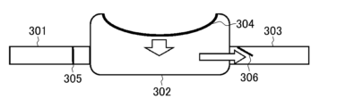
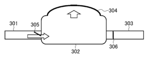
- the diaphragm pump consists of a suction port 301 , a pump main body 302 and a discharge port 303 .
- Pump body 302 includes diaphragm 304 . Due to the change in volume of the pump body 302 caused by the deformation of the diaphragm 304, gas or liquid is taken in through the suction port 301, and the gas or liquid taken in is discharged through the discharge port 303 according to the change in volume.
- an intake valve 305 and an exhaust valve 306 are provided at the intake port 301 and the exhaust port 303 in order to easily control the flow of gas or liquid according to volume changes.
- the function as a pump is realized by causing the volume change of the pump body 302 caused by vibrating the diaphragm (partition wall) 304 to cause the gas or liquid to flow from the suction port toward the discharge port.
- Micro-diaphragm pumps already on the market use piezo-electric materials and MEMS (Micro Electro Mechanical Systems) to miniaturize the parts corresponding to the diaphragm, and even if the pump has a structure without intake/exhaust valves, which makes it difficult to keep up with the response speed.
- MEMS Micro Electro Mechanical Systems
- a valveless design is adopted that can control the flow direction of gas and liquid inside (Non-Patent Document 1).
- Micro-diaphragm pumps that use MEMS have problems with partial wear due to repeated shrinkage of semiconductor devices, which are MEMS materials, and wear failure due to pressure loads applied to the MEMS itself by flowing gas or liquid.
- MEMS semiconductor devices
- wear failure due to pressure loads applied to the MEMS itself by flowing gas or liquid.
- such a countermeasure has a trade-off with other characteristics, and is a difficult subject.
- conventionally there has been the problem that it is not easy to improve the performance of minute microdiaphragm pumps.
- the present invention was made to solve the above problems, and aims to improve the performance of minute micro-diaphragm pumps.
- a micro-diaphragm pump comprises a main body having a recess, a diaphragm covering an opening of the recess and defining a pump chamber together with the main body and made of a crystal material having an electrostrictive effect, and a diaphragm on one side of the diaphragm. It has a first electrode ohmically connected and a second electrode ohmically connected to the other surface of the diaphragm.
- the diaphragm is made of a crystal material having an electrostrictive effect
- the first electrode is ohmically connected to one surface of the diaphragm
- the second electrode is ohmically connected to the other surface. Therefore, it is possible to realize high performance of a minute microdiaphragm pump.
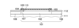
- FIG. 1A is a cross-sectional view showing the configuration of a micro-diaphragm pump according to an embodiment of the invention.
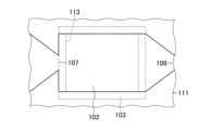
- FIG. 1B is a plan view showing a partial configuration of the micro-diaphragm pump according to the embodiment of the invention.
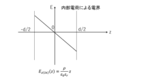
- FIG. 2A is a characteristic diagram showing the relationship between the position of the KTN crystal in the direction perpendicular to the electrode surface and the electric field due to internal charges.
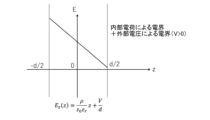
- FIG. 2B is a characteristic diagram showing the relationship between the position in the direction perpendicular to the electrode surface of the KTN crystal when the electric field due to the external voltage is added to the electric field due to the internal charge.
- FIG. 1A is a cross-sectional view showing the configuration of a micro-diaphragm pump according to an embodiment of the invention.
- FIG. 1B is a plan view showing a partial configuration of the micro-diaphragm pump according to the embodiment of the invention.
- FIG. 2A is a characteristic diagram showing the relationship between the
- FIG. 3 is an explanatory diagram for explaining the relationship between the amount of crystal shrinkage in the x and y directions and the position z in a KTN crystal obtained by adding an electric field due to an internal charge to an electric field due to an external voltage.
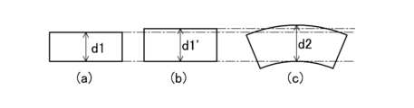
- FIG. 4 is an explanatory diagram for explaining the distortion change of a KTN crystal with and without warping due to charge injection.
- FIG. 5 is a characteristic diagram showing the difference in displacement of the KTN crystal between (a) with charge injection and (b) without charge injection.
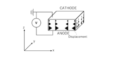
- FIG. 6A is a perspective view showing the configuration of a diaphragm pump.
- FIG. 6B is a cross-sectional view showing the configuration of the diaphragm pump.
- FIG. 6C is a cross-sectional view showing the configuration of the diaphragm pump.
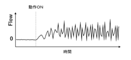
- FIG. 7A is a characteristic diagram showing a pulsating state in which the discharge flow rate of the diaphragm pump is not constant.
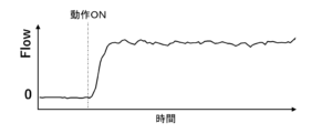
- FIG. 7B is a characteristic diagram showing a state where there is no pulsation in the discharge flow rate of the diaphragm pump.
- This microdiaphragm pump comprises a main body 101 having a recess, a diaphragm 103 covering the opening of the recess and defining a pump chamber 102 together with the main body 101, a first electrode 104 and a second electrode 105.
- the first electrode 104 can be the anode electrode and the second electrode 105 can be the cathode electrode.
- Diaphragm 103 is made of a crystal material having an electrostrictive effect. Diaphragm 103 may be constructed from a transparent crystalline material with an electrostrictive effect.
- the diaphragm 103 is made of cubic KTN [KTa 1- ⁇ Nb ⁇ O 3 (0 ⁇ 1)] crystal or cubic KLTN [K 1- ⁇ Li ⁇ Ta 1- ⁇ Nb ⁇ O with added lithium. 3 (0 ⁇ 1, 0 ⁇ 1)] crystals.
- the first electrode 104 is ohmic-connected to one surface of the diaphragm 103
- the second electrode 105 is ohmic-connected to the other surface of the diaphragm 103
- the first electrode 104 and the second electrode 105 can have a laminated structure of a metal such as titanium or nickel and a metal such as platinum or gold-A.
- a metal such as titanium or nickel is deposited at each electrode formation location by vapor deposition or the like, and then a metal such as platinum or gold A is deposited at each electrode formation location by vapor deposition or the like to obtain the first electrode 104, the second electrode 104, or the like.
- the first electrode 104 and the second electrode 105 thus formed can be ohmic-connected to the diaphragm 103 .
- heat treatment for example, 400° C./min is performed to adjust the ohmic resistance between the deposited metal material and the diaphragm 103, Can be ohmic connected.
- the first electrode 104 and the second electrode 105 perform voltage application in the plate thickness direction of the diaphragm 103 and charge injection into the diaphragm 103 .
- the first electrode 104 and the second electrode 105 can be formed around the diaphragm 103 excluding the central portion of the diaphragm 103 .
- the fluid flowing through the pump chamber 102 can be optically observed from the outside.
- each electrode by forming each electrode from a multilayer film made of a material such as tin or indium and making it transparent at a target wavelength, a configuration in which the inside of the pump chamber 102 can be observed can be realized.
- the main body 101 can be composed of, for example, a substrate 111 made of single crystal Si and an upper plate 112 made of single crystal Si fixed on the substrate 111 .
- the upper plate 112 is provided with an opening 113 at the position of the concave portion that serves as the pump chamber 102 of the substrate 111 .
- a diaphragm 103 is formed to close the opening 113 of the upper plate 112 .
- the distance (interval) between the bottom surface and the diaphragm 103 serving as the ceiling is about 50 ⁇ m
- the width in plan view is 200 ⁇ m
- the depth in the direction of flow path is 3000 ⁇ m.
- a first electrode 104 is formed on the upper surface of the upper plate 112 around the opening 113 , and the first electrode 104 is sandwiched between the upper plate 112 and the peripheral portion of the diaphragm 103 .
- a second electrode 105 is formed at a position facing the first electrode 104 with the diaphragm 103 interposed therebetween.
- forming the second electrode 105 on the diaphragm 103 is facilitated by making the diaphragm 103 in the initial state recessed toward the pump chamber 102 side.
- This micro-diaphragm pump also has an intake port 107 formed in the pump chamber 102 for sucking the target fluid into the pump chamber 102 and an exhaust port 107 formed in the pump chamber 102 for pushing out the fluid from the pump chamber 102 . and an outlet 108 .
- the cross-sectional size of the pump chamber 102 perpendicular to the transfer direction is reduced as it approaches the discharge port 108 .
- the width of the pump chamber 102 in plan view can be 200 ⁇ m, and the opening width of the discharge port 108 can be 50 ⁇ m. With this configuration, the discharge pressure at the discharge port 108 can be made smaller than that at the suction port 107 .
- a flow path 109 is connected to the suction port 107 .
- the flow path 109 has a smaller cross-sectional size perpendicular to the transfer direction as it approaches the suction port 107 .
- the width of the pump chamber 102 in plan view can be set to 200 ⁇ m, and the opening width of the suction port 107 can be set to 50 ⁇ m. With this configuration, backflow from the pump chamber 102 side to the suction port 107 side is less likely to occur.
- first electrode 104 and the second electrode 105 are ohmic-connected to the diaphragm 103, voltage application in the thickness direction of the diaphragm 103 and charge injection into the diaphragm 103 can be realized. .
- the diaphragm 103 is made of a crystal material having an electrostrictive effect such as KTN, which can be expected to have a high-speed response on the order of MHz.
- the electrostrictive effect is smaller than the piezoelectric effect, and it is considered disadvantageous to use a crystal material such as KTN that exhibits electrostrictive properties for the diaphragm 103 .
- a KTN crystal is a cubic crystal, and an electrostrictive effect occurs when an electric field exists inside the crystal.
- This electrostrictive effect will be explained using a KTN crystal as an example.
- forming an electrode on a KTN crystal and applying a voltage causes an electrostrictive effect, causing the KTN crystal to expand in the direction of the electric field and contract in the direction perpendicular to the electric field.
- the distortion due to the electrostrictive effect is expressed by the following formula, where e is the distortion, Q is the electrostrictive coefficient, and P is the polarization.
- the polarization P is proportional to the electric field E.
- E the electric field E due to the external voltage
- V the voltage
- d the distance between the electrodes
- this electrostrictive effect is a phenomenon that occurs only when the KTN crystal is a cubic crystal.
- the crystal structure of the KTN crystal is temperature dependent, and becomes cubic when the KTN crystal is above the Curie temperature.
- the polarization P can be considered to be proportional to the dielectric constant ⁇ r . Since the relative dielectric constant ⁇ r has temperature dependence, temperature control is also important for stably generating the electrostrictive effect.
- the polarization P z satisfies the following relationship.
- the amount of crystal shrinkage in the x and y directions varies depending on the position z.
- the crystal is warped such that the cathode side is convex.
- d1(a) is the distance from the center of gravity of the bottom surface of the KTN crystal to the center of top surface of the KTN crystal with no voltage applied
- d1' is the distance from the center of gravity of the bottom surface of the KTN crystal to the center of top surface of the KTN crystal with no internal charge and voltage applied
- d2(c) is the distance from the center of gravity of the bottom surface of the KTN crystal to the center of gravity of the top surface when there is an internal voltage and voltage is applied.
- the cathode electrode (second electrode 105) is fixed at the ground level and the potential of the anode electrode (first electrode 104) is driven in the range of 0V to 100V
- the volume of the pump chamber 102 increases compared to the state at 0V. In this state, gas or liquid is taken into the pump chamber 102 from the suction port 107 due to the pressure difference between the suction port 107 and the discharge port 108 as seen from the pump chamber 102 .
- the volume of the pump chamber 102 is set to the initial state, and the gas or liquid drawn into the pump chamber 102 flows out of the pump chamber 102. Ejected. In this state, a large amount of gas or liquid is discharged from the discharge port 108 having a smaller discharge resistance than the suction port 107 .
- the voltage signal applied to the diaphragm 103 to operate it, it can be driven as a diaphragm pump.
- the voltage control applied to the diaphragm 103 it is not always necessary to fix either the cathode electrode/anode electrode to the ground potential.
- the diaphragm 103 made of KTN is capable of a high-speed response of about 1 MHz, enabling control faster than the generally used response speed (several tens of kHz to 100 kHz) due to the piezo effect.
- By controlling the operation of the diaphragm 103 at high speed it is possible to suppress pulsation, which is a problem in diaphragm pumps without mechanical valves, and to control the flow rate of gas or liquid more precisely.
- flow rate control for a gas that has a small frictional resistance against the inner wall of the pump chamber 102 or the like in other words, a large drop in pump efficiency due to the return of the fluid to the suction port 107 side, and a large pump loss.
- the diaphragm 103 made of KTN at high speed it is important to reduce the capacitance of the diaphragm 103 .
- KTN crystals are used in a temperature range in which they become cubic, but cubic KTN crystals are colorless and transparent (reference document 3).
- a part of the electrode of the diaphragm 103 made of KTN is provided with a portion through which light is transmitted, or the electrode is made of a transparent material, so that the pump chamber 102 portion can be exposed to light, and the pump chamber 102 can be It becomes possible to detect the reflected light of
- Such an optical method makes it possible to analyze the components of the gas or liquid passing through the pump chamber 102, monitor foreign substances contained in the gas or liquid, and detect changes in the density of the gas or liquid.
- the microdiaphragm pump can be applied as a biomedical device, such as a ⁇ -TAS having a pump function.
- the diaphragm 103 may dissolve in the fluid to be transferred (transported), or deteriorate due to chemical reaction with the fluid or substances in the fluid.
- the surface of the diaphragm 103 on the pump chamber 102 side can be further provided with a protective film that protects the diaphragm 103 from the fluid.
- a protective film that protects the diaphragm 103 at a portion where the diaphragm 103 contacts the fluid. It can be composed of non-reactive substances. Degradation of the diaphragm 103 can be prevented by forming the protective film.
- a protective film may be formed on the surface of the diaphragm 103 or the electrode surface inside the diaphragm 103 for the purpose of making it difficult for the fluid to stay on the surface of the diaphragm 103 .
- the diaphragm is made of a crystal material having an electrostrictive effect
- the first electrode is ohmically connected to one surface of the diaphragm
- the second electrode is ohmically connected to the other surface.
Landscapes
- Engineering & Computer Science (AREA)
- Mechanical Engineering (AREA)
- General Engineering & Computer Science (AREA)
- Reciprocating Pumps (AREA)
Priority Applications (3)
| Application Number | Priority Date | Filing Date | Title |
|---|---|---|---|
| PCT/JP2021/044691 WO2023105565A1 (ja) | 2021-12-06 | 2021-12-06 | マイクロダイアフラムポンプ |
| US18/699,720 US20240410350A1 (en) | 2021-12-06 | 2021-12-06 | Micro diaphragm pump |
| JP2023565673A JPWO2023105565A1 (cg-RX-API-DMAC7.html) | 2021-12-06 | 2021-12-06 |
Applications Claiming Priority (1)
| Application Number | Priority Date | Filing Date | Title |
|---|---|---|---|
| PCT/JP2021/044691 WO2023105565A1 (ja) | 2021-12-06 | 2021-12-06 | マイクロダイアフラムポンプ |
Publications (1)
| Publication Number | Publication Date |
|---|---|
| WO2023105565A1 true WO2023105565A1 (ja) | 2023-06-15 |
Family
ID=86729803
Family Applications (1)
| Application Number | Title | Priority Date | Filing Date |
|---|---|---|---|
| PCT/JP2021/044691 Ceased WO2023105565A1 (ja) | 2021-12-06 | 2021-12-06 | マイクロダイアフラムポンプ |
Country Status (3)
| Country | Link |
|---|---|
| US (1) | US20240410350A1 (cg-RX-API-DMAC7.html) |
| JP (1) | JPWO2023105565A1 (cg-RX-API-DMAC7.html) |
| WO (1) | WO2023105565A1 (cg-RX-API-DMAC7.html) |
Citations (11)
| Publication number | Priority date | Publication date | Assignee | Title |
|---|---|---|---|---|
| JPH05172672A (ja) * | 1991-12-26 | 1993-07-09 | Showa Denko Kk | 半導体圧電素子 |
| JPH0893721A (ja) * | 1994-09-22 | 1996-04-09 | Aisin Kosumosu Kenkyusho:Kk | マイクロアクチュエ−タ |
| JP2001132646A (ja) * | 1999-11-10 | 2001-05-18 | Hitachi Ltd | ダイヤフラムポンプ |
| JP2001263486A (ja) * | 2000-03-22 | 2001-09-26 | Matsushita Electric Works Ltd | ダイヤフラム及びダイヤフラムポンプ並びにダイヤフラムの製造方法 |
| JP2003074475A (ja) * | 2001-04-06 | 2003-03-12 | Ngk Insulators Ltd | マイクロポンプ |
| WO2003033399A1 (en) * | 2001-10-15 | 2003-04-24 | Ngk Insulators, Ltd. | Drive device |
| JP2007529113A (ja) * | 2003-11-26 | 2007-10-18 | ザ・ペン・ステート・リサーチ・ファンデーション | Idt電極を持つ圧電ダイアフラム |
| JP2010163929A (ja) * | 2009-01-14 | 2010-07-29 | Tokai Rubber Ind Ltd | ダイヤフラム式ポンプ |
| JP2011008227A (ja) * | 2009-05-29 | 2011-01-13 | Nippon Telegr & Teleph Corp <Ntt> | 電気光学デバイス |
| WO2011007646A1 (ja) * | 2009-07-17 | 2011-01-20 | 株式会社村田製作所 | 金属板と圧電体との接着構造及び接着方法 |
| WO2021214865A1 (ja) * | 2020-04-21 | 2021-10-28 | 日本電信電話株式会社 | 波長可変光フィルタ |
Family Cites Families (3)
| Publication number | Priority date | Publication date | Assignee | Title |
|---|---|---|---|---|
| US4264838A (en) * | 1979-10-01 | 1981-04-28 | Sperry Corporation | Force balanced piezoelectric vibratory rate sensor |
| JP3629405B2 (ja) * | 2000-05-16 | 2005-03-16 | コニカミノルタホールディングス株式会社 | マイクロポンプ |
| US7094040B2 (en) * | 2002-03-27 | 2006-08-22 | Minolta Co., Ltd. | Fluid transferring system and micropump suitable therefor |
-
2021
- 2021-12-06 JP JP2023565673A patent/JPWO2023105565A1/ja active Pending
- 2021-12-06 WO PCT/JP2021/044691 patent/WO2023105565A1/ja not_active Ceased
- 2021-12-06 US US18/699,720 patent/US20240410350A1/en not_active Abandoned
Patent Citations (11)
| Publication number | Priority date | Publication date | Assignee | Title |
|---|---|---|---|---|
| JPH05172672A (ja) * | 1991-12-26 | 1993-07-09 | Showa Denko Kk | 半導体圧電素子 |
| JPH0893721A (ja) * | 1994-09-22 | 1996-04-09 | Aisin Kosumosu Kenkyusho:Kk | マイクロアクチュエ−タ |
| JP2001132646A (ja) * | 1999-11-10 | 2001-05-18 | Hitachi Ltd | ダイヤフラムポンプ |
| JP2001263486A (ja) * | 2000-03-22 | 2001-09-26 | Matsushita Electric Works Ltd | ダイヤフラム及びダイヤフラムポンプ並びにダイヤフラムの製造方法 |
| JP2003074475A (ja) * | 2001-04-06 | 2003-03-12 | Ngk Insulators Ltd | マイクロポンプ |
| WO2003033399A1 (en) * | 2001-10-15 | 2003-04-24 | Ngk Insulators, Ltd. | Drive device |
| JP2007529113A (ja) * | 2003-11-26 | 2007-10-18 | ザ・ペン・ステート・リサーチ・ファンデーション | Idt電極を持つ圧電ダイアフラム |
| JP2010163929A (ja) * | 2009-01-14 | 2010-07-29 | Tokai Rubber Ind Ltd | ダイヤフラム式ポンプ |
| JP2011008227A (ja) * | 2009-05-29 | 2011-01-13 | Nippon Telegr & Teleph Corp <Ntt> | 電気光学デバイス |
| WO2011007646A1 (ja) * | 2009-07-17 | 2011-01-20 | 株式会社村田製作所 | 金属板と圧電体との接着構造及び接着方法 |
| WO2021214865A1 (ja) * | 2020-04-21 | 2021-10-28 | 日本電信電話株式会社 | 波長可変光フィルタ |
Also Published As
| Publication number | Publication date |
|---|---|
| US20240410350A1 (en) | 2024-12-12 |
| JPWO2023105565A1 (cg-RX-API-DMAC7.html) | 2023-06-15 |
Similar Documents
| Publication | Publication Date | Title |
|---|---|---|
| Linnemann et al. | A self-priming and bubble-tolerant piezoelectric silicon micropump for liquids and gases | |
| US4938742A (en) | Piezoelectric micropump with microvalves | |
| CN107735573B (zh) | 泵 | |
| US6869275B2 (en) | Piezoelectrically driven fluids pump and piezoelectric fluid valve | |
| US8353682B2 (en) | Microfluidic-device systems and methods for manufacturing microfluidic-device systems | |
| JP5850208B1 (ja) | 流体制御装置およびポンプ | |
| US11454232B2 (en) | Micro-electromechanical systems pump | |
| Zhou et al. | Discrete microfluidics based on aluminum nitride surface acoustic wave devices | |
| BR112012022433B1 (pt) | Método para fabricação de um transdutor de dobra, uma microbomba e uma microválvula, microbomba e microválvula | |
| US11835041B2 (en) | Thin MEMS pump with membrane and valve lip structure | |
| Chen et al. | A normally-closed piezoelectric micro-valve with flexible stopper | |
| JP2001322099A (ja) | マイクロポンプ | |
| CN111659479A (zh) | 一种用于微粒子分离的超声表面驻波微流控芯片设计方法 | |
| WO2026011720A1 (zh) | Mems传感器和电子雾化装置 | |
| US20100059127A1 (en) | Piezoelectric pump and fluid transferring system | |
| WO2018181023A1 (ja) | キャピラリーおよびそれを用いたピペット | |
| US20090314062A1 (en) | Fluid Actuator, and Heat Generating Device and Analysis Device Using the Same | |
| US8668474B2 (en) | Electro-active valveless pump | |
| US20240410350A1 (en) | Micro diaphragm pump | |
| JP2019171329A (ja) | ピペットおよびそれを用いた液体採取方法 | |
| CN115350395A (zh) | 一种可变流向的压电无阀泵及其控制装置 | |
| JP6089560B2 (ja) | 気体制御装置 | |
| JP6974245B2 (ja) | キャピラリーおよびそれを用いたピペット | |
| CN115178314B (zh) | 一种微机电系统微流体装置及其制作方法 | |
| TWI861533B (zh) | 電子裝置 |
Legal Events
| Date | Code | Title | Description |
|---|---|---|---|
| 121 | Ep: the epo has been informed by wipo that ep was designated in this application |
Ref document number: 21967072 Country of ref document: EP Kind code of ref document: A1 |
|
| ENP | Entry into the national phase |
Ref document number: 2023565673 Country of ref document: JP Kind code of ref document: A |
|
| NENP | Non-entry into the national phase |
Ref country code: DE |
|
| 122 | Ep: pct application non-entry in european phase |
Ref document number: 21967072 Country of ref document: EP Kind code of ref document: A1 |