WO2023101013A1 - 露光システム、配向膜の形成方法、光学素子の製造方法、および、光学素子 - Google Patents
露光システム、配向膜の形成方法、光学素子の製造方法、および、光学素子 Download PDFInfo
- Publication number
- WO2023101013A1 WO2023101013A1 PCT/JP2022/044588 JP2022044588W WO2023101013A1 WO 2023101013 A1 WO2023101013 A1 WO 2023101013A1 JP 2022044588 W JP2022044588 W JP 2022044588W WO 2023101013 A1 WO2023101013 A1 WO 2023101013A1
- Authority
- WO
- WIPO (PCT)
- Prior art keywords
- light
- liquid crystal
- optical
- optical element
- exposure system
- Prior art date
- Legal status (The legal status is an assumption and is not a legal conclusion. Google has not performed a legal analysis and makes no representation as to the accuracy of the status listed.)
- Ceased
Links
Images







Classifications
-
- G—PHYSICS
- G03—PHOTOGRAPHY; CINEMATOGRAPHY; ANALOGOUS TECHNIQUES USING WAVES OTHER THAN OPTICAL WAVES; ELECTROGRAPHY; HOLOGRAPHY
- G03F—PHOTOMECHANICAL PRODUCTION OF TEXTURED OR PATTERNED SURFACES, e.g. FOR PRINTING, FOR PROCESSING OF SEMICONDUCTOR DEVICES; MATERIALS THEREFOR; ORIGINALS THEREFOR; APPARATUS SPECIALLY ADAPTED THEREFOR
- G03F7/00—Photomechanical, e.g. photolithographic, production of textured or patterned surfaces, e.g. printing surfaces; Materials therefor, e.g. comprising photoresists; Apparatus specially adapted therefor
- G03F7/70—Microphotolithographic exposure; Apparatus therefor
- G03F7/70216—Mask projection systems
- G03F7/70225—Optical aspects of catadioptric systems, i.e. comprising reflective and refractive elements
-
- G—PHYSICS
- G02—OPTICS
- G02B—OPTICAL ELEMENTS, SYSTEMS OR APPARATUS
- G02B13/00—Optical objectives specially designed for the purposes specified below
- G02B13/18—Optical objectives specially designed for the purposes specified below with lenses having one or more non-spherical faces, e.g. for reducing geometrical aberration
-
- G—PHYSICS
- G02—OPTICS
- G02B—OPTICAL ELEMENTS, SYSTEMS OR APPARATUS
- G02B3/00—Simple or compound lenses
- G02B3/02—Simple or compound lenses with non-spherical faces
-
- G—PHYSICS
- G02—OPTICS
- G02B—OPTICAL ELEMENTS, SYSTEMS OR APPARATUS
- G02B5/00—Optical elements other than lenses
- G02B5/04—Prisms
-
- G—PHYSICS
- G02—OPTICS
- G02B—OPTICAL ELEMENTS, SYSTEMS OR APPARATUS
- G02B5/00—Optical elements other than lenses
- G02B5/30—Polarising elements
-
- G—PHYSICS
- G02—OPTICS
- G02B—OPTICAL ELEMENTS, SYSTEMS OR APPARATUS
- G02B5/00—Optical elements other than lenses
- G02B5/32—Holograms used as optical elements
-
- G—PHYSICS
- G02—OPTICS
- G02F—OPTICAL DEVICES OR ARRANGEMENTS FOR THE CONTROL OF LIGHT BY MODIFICATION OF THE OPTICAL PROPERTIES OF THE MEDIA OF THE ELEMENTS INVOLVED THEREIN; NON-LINEAR OPTICS; FREQUENCY-CHANGING OF LIGHT; OPTICAL LOGIC ELEMENTS; OPTICAL ANALOGUE/DIGITAL CONVERTERS
- G02F1/00—Devices or arrangements for the control of the intensity, colour, phase, polarisation or direction of light arriving from an independent light source, e.g. switching, gating or modulating; Non-linear optics
- G02F1/01—Devices or arrangements for the control of the intensity, colour, phase, polarisation or direction of light arriving from an independent light source, e.g. switching, gating or modulating; Non-linear optics for the control of the intensity, phase, polarisation or colour
- G02F1/13—Devices or arrangements for the control of the intensity, colour, phase, polarisation or direction of light arriving from an independent light source, e.g. switching, gating or modulating; Non-linear optics for the control of the intensity, phase, polarisation or colour based on liquid crystals, e.g. single liquid crystal display cells
- G02F1/133—Constructional arrangements; Operation of liquid crystal cells; Circuit arrangements
- G02F1/1333—Constructional arrangements; Manufacturing methods
- G02F1/1337—Surface-induced orientation of the liquid crystal molecules, e.g. by alignment layers
- G02F1/133753—Surface-induced orientation of the liquid crystal molecules, e.g. by alignment layers with different alignment orientations or pretilt angles on a same surface, e.g. for grey scale or improved viewing angle
- G02F1/133757—Surface-induced orientation of the liquid crystal molecules, e.g. by alignment layers with different alignment orientations or pretilt angles on a same surface, e.g. for grey scale or improved viewing angle with different alignment orientations
-
- G—PHYSICS
- G02—OPTICS
- G02F—OPTICAL DEVICES OR ARRANGEMENTS FOR THE CONTROL OF LIGHT BY MODIFICATION OF THE OPTICAL PROPERTIES OF THE MEDIA OF THE ELEMENTS INVOLVED THEREIN; NON-LINEAR OPTICS; FREQUENCY-CHANGING OF LIGHT; OPTICAL LOGIC ELEMENTS; OPTICAL ANALOGUE/DIGITAL CONVERTERS
- G02F1/00—Devices or arrangements for the control of the intensity, colour, phase, polarisation or direction of light arriving from an independent light source, e.g. switching, gating or modulating; Non-linear optics
- G02F1/01—Devices or arrangements for the control of the intensity, colour, phase, polarisation or direction of light arriving from an independent light source, e.g. switching, gating or modulating; Non-linear optics for the control of the intensity, phase, polarisation or colour
- G02F1/13—Devices or arrangements for the control of the intensity, colour, phase, polarisation or direction of light arriving from an independent light source, e.g. switching, gating or modulating; Non-linear optics for the control of the intensity, phase, polarisation or colour based on liquid crystals, e.g. single liquid crystal display cells
- G02F1/133—Constructional arrangements; Operation of liquid crystal cells; Circuit arrangements
- G02F1/1333—Constructional arrangements; Manufacturing methods
- G02F1/1337—Surface-induced orientation of the liquid crystal molecules, e.g. by alignment layers
- G02F1/13378—Surface-induced orientation of the liquid crystal molecules, e.g. by alignment layers by treatment of the surface, e.g. embossing, rubbing or light irradiation
- G02F1/133788—Surface-induced orientation of the liquid crystal molecules, e.g. by alignment layers by treatment of the surface, e.g. embossing, rubbing or light irradiation by light irradiation, e.g. linearly polarised light photo-polymerisation
-
- G—PHYSICS
- G02—OPTICS
- G02F—OPTICAL DEVICES OR ARRANGEMENTS FOR THE CONTROL OF LIGHT BY MODIFICATION OF THE OPTICAL PROPERTIES OF THE MEDIA OF THE ELEMENTS INVOLVED THEREIN; NON-LINEAR OPTICS; FREQUENCY-CHANGING OF LIGHT; OPTICAL LOGIC ELEMENTS; OPTICAL ANALOGUE/DIGITAL CONVERTERS
- G02F1/00—Devices or arrangements for the control of the intensity, colour, phase, polarisation or direction of light arriving from an independent light source, e.g. switching, gating or modulating; Non-linear optics
- G02F1/29—Devices or arrangements for the control of the intensity, colour, phase, polarisation or direction of light arriving from an independent light source, e.g. switching, gating or modulating; Non-linear optics for the control of the position or the direction of light beams, i.e. deflection
- G02F1/294—Variable focal length devices
-
- G—PHYSICS
- G03—PHOTOGRAPHY; CINEMATOGRAPHY; ANALOGOUS TECHNIQUES USING WAVES OTHER THAN OPTICAL WAVES; ELECTROGRAPHY; HOLOGRAPHY
- G03F—PHOTOMECHANICAL PRODUCTION OF TEXTURED OR PATTERNED SURFACES, e.g. FOR PRINTING, FOR PROCESSING OF SEMICONDUCTOR DEVICES; MATERIALS THEREFOR; ORIGINALS THEREFOR; APPARATUS SPECIALLY ADAPTED THEREFOR
- G03F7/00—Photomechanical, e.g. photolithographic, production of textured or patterned surfaces, e.g. printing surfaces; Materials therefor, e.g. comprising photoresists; Apparatus specially adapted therefor
- G03F7/20—Exposure; Apparatus therefor
Definitions
- the present invention relates to an exposure system that generates interference light, a method for forming an alignment film using this exposure system, a method for manufacturing an optical element using this alignment film, and an optical element.
- Optical elements that control the direction of light are used in many optical systems.
- the backlight of the liquid crystal display device AR (Augmented Reality) glasses that display virtual images and various information superimposed on the actual scene, and the artificially created virtual space.
- Head Mounted Display HMD (Head Mounted Display)
- VR Virtual Reality
- Optical elements that control the direction of light are used in various optical devices, such as sensors in .
- Non-Patent Document 1 and Patent Document 1 disclose an optical element ( In a liquid crystal diffractive lens), an optical element having regions with different focal lengths within a plane has been proposed.
- an optical element having a concentric liquid crystal alignment pattern as described above acts as a condensing or diverging lens by gradually shortening one period from the inner side (optical axis) to the outer side.
- the shorter the period the greater the diffraction, so the shorter the focal length.
- the decrease in the length of one period is an inversely proportional monotonic decrease, and the focal length is almost constant over the entire surface in the plane, that is, in the direction perpendicular to the optical axis. is.
- regions with different focal lengths can be formed within the plane of the optical element.
- An optical element is usually produced by forming an alignment film having an alignment pattern corresponding to the liquid crystal alignment pattern, and forming an optically anisotropic layer containing a liquid crystal compound on the alignment film. Therefore, in order to produce an optical element having the desired optical characteristics, it is necessary to form an alignment pattern corresponding to the liquid crystal alignment pattern for realizing the desired optical characteristics on the alignment film.
- a photo-alignment film that forms an alignment pattern by light irradiation, that is, exposure is preferably used.
- an alignment pattern having regions with different focal lengths in the plane Patent Document 2 and a direct writing exposure method as described in Non-Patent Document 2, and an exposure method using a mask as described in Patent Document 3 and Non-Patent Document 1 are known.
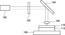
- a light beam emitted from a light source 100 is transmitted through a rotatable polarization conversion element 102 (half-wave plate) to rotate the polarization direction.
- Linearly polarized light is reflected by a mirror 104 as necessary, condensed by a condensing lens 106, and formed into an image on an unexposed photo-alignment film 110 placed on an xy stage 108.
- the unexposed photo-alignment film 110 is supported by the glass substrate 112 .
- the unexposed photo-alignment film 110 (photo-alignment film) can be exposed to, for example, A desired orientation pattern is formed corresponding to an optical element having regions with different focal lengths in the plane.
- this direct drawing exposure method it is possible to manufacture an alignment film having various alignment patterns according to the purpose with a high degree of freedom, that is, an optical element having various liquid crystal alignment patterns.
- this direct writing exposure method has the problem that it takes a lot of time to write the intended pattern, resulting in low productivity.
- Patent Document 3 as an exposure method using a mask, a birefringent mask corresponding to a liquid crystal alignment pattern to be formed is used, and an unexposed alignment film is exposed through this mask to achieve the desired result.
- a method is described for forming an alignment pattern that In this exposure method, a birefringent mask is formed by a direct writing exposure method, and the alignment film is exposed using the birefringent mask to form an alignment pattern, thereby achieving both design flexibility and productivity. ing.
- this exposure method light that cannot be completely bent by the birefringent mask becomes noise light, making it difficult to form an orientation pattern with high accuracy.
- Non-Patent Document 1 describes an exposure method using a mask in exposure of an alignment pattern using interference.
- this interference exposure method light transmitted through a linear polarizer is split into two by a polarization beam splitter, and the split light is converted into circularly polarized light by a quarter-wave plate.
- both circularly polarized lights are combined by a beam combiner (beam splitter) to cause interference, and the unexposed alignment film is exposed by the interference light.
- a concentric alignment pattern as described above can be formed on the alignment film.
- the length of one period in the alignment pattern is determined by the focal length of the lens.
- the alignment pattern having regions with different focal lengths in the plane is repeated by adjusting the focal length of the lens and exposing unnecessary portions to light with a mask. forming
- this exposure method cannot form an area where the focal length changes continuously within the plane.
- a non-uniform boundary region (Boundary) occurs at the boundary between regions with different focal lengths, making it impossible to form an appropriate liquid crystal alignment pattern. There is a problem of difficulty. Such non-uniform boundary regions and alignment pattern disturbances cause unnecessary images called ghosts and multiple images.
- An object of the present invention is to solve such problems of the prior art, and to easily form an alignment film for manufacturing an optical element having a region where the focal length continuously changes without a boundary region. It is an object of the present invention to provide an exposure system capable of controlling the exposure system, a method of forming an alignment film using this exposure system, a method of manufacturing an optical element using this alignment film, and an optical element capable of suppressing the occurrence of ghosts and multiple images.
- the present invention has the following configurations.
- a light source a beam splitter element that splits the light emitted by the light source; A first surface that receives light split by the beam splitter element and transmits at least a portion of the incident light, and another surface that receives light split by the beam splitter element and reflects at least a portion of the incident light.
- a beam combiner element having a second surface and emitting light obtained by superimposing the light transmitted through the first surface and the light reflected by the second surface; A condensing light provided in at least one of the optical path of the first light incident on the first surface of the beam combiner element and the optical path of the second light incident on the second surface of the beam combiner element.
- At least one of the condensing elements is a focus changing condensing element having a focal length fL that continuously changes in a direction orthogonal to the optical axis, and the ratio between the maximum value fLmax and the minimum value fLmin of the focal length fL is "fLmax /fLmin” is greater than 1.1.
- a beam expander element at least one of between the light source and the beam splitter element, between the beam splitter element and the beam combiner element, and at a position where light is not condensed. , [1].
- At least part of the light emitted from the beam combiner element forms an angle of 15° or more with respect to the optical axis of the focus-changing light-collecting element when parallel light is incident on the focus-changing light-collecting element, [ 1] The exposure system according to any one of [5]. [7] The ratio of the maximum value to the minimum value of the intensity of light in the direction perpendicular to the optical axis of the focal point changing light-collecting element is 25 times or less at the exposure surface, [1]- [6] The exposure system according to any one of [6]. [8] The exposure system according to any one of [1] to [7], wherein the optical path length between the beam splitter element and the beam combiner element is 800 mm or less.
- a method for forming an alignment film comprising exposing a coating film containing a compound having a photoalignment group with the exposure system according to any one of [1] to [11].
- a method for producing an optical element comprising applying a composition containing a liquid crystal compound to an alignment film formed by the method for forming an alignment film according to [12], and drying the composition.
- the optical element has a focal length fG that continuously changes in the outward direction from the center of the concentric circles, A ratio "fGmax/fGmin" between the maximum value fGmax and the minimum value fGmin of the focal length fG is greater than 1.1, Rmax is 3, where Rmax is the ratio of the intensity of the 0th-order light to the intensity of the 1st-order light at the position in the plane of the optical element where the ratio of the intensity of the 0th-order light to the intensity of the 1st-order light is the largest.
- Xmax is the ratio of the intensity of the diffracted light having the highest intensity among the diffracted lights with diffraction angles smaller than the diffraction angle of the 1st-order light to the intensity of the 1st-order light
- the ratio Xmax is the highest in the plane of the optical element.
- An optical element in which the ratio Xmax at the position where it becomes large is 3% or less.
- a first liquid crystal layer in which the bright and dark lines are inclined with respect to the main surface; a second liquid crystal layer in which the direction of inclination of the light and dark lines is opposite to that of the first liquid crystal layer; At least three liquid crystal layers, including a third liquid crystal layer provided between the first liquid crystal layer and the second liquid crystal layer, and a third liquid crystal layer having a larger angle of the light-dark line with respect to the principal surface than the first liquid crystal layer and the second liquid crystal layer;
- the optical element according to [17].
- an alignment film for manufacturing an optical element having a region where the focal length changes continuously without a boundary region it is possible to easily form an alignment film for manufacturing an optical element having a region where the focal length changes continuously without a boundary region. Further, according to the method for manufacturing an optical element and the optical element of the present invention, an optical element that has a liquid crystal alignment pattern that has a region in which the focal length changes continuously without a boundary region, and suppresses the generation of ghosts and multiple images. easily obtained.
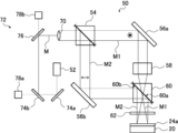
- FIG. 1 is a diagram conceptually showing an example of the exposure system of the present invention.
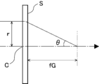
- FIG. 2 is a conceptual diagram for explaining the focal length of the condensing element.
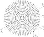
- FIG. 3 is a diagram conceptually showing an example of an orientation pattern by normal interference exposure.
- FIG. 4 conceptually shows the focal length profile of a normal condensing element.
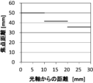
- FIG. 5 is a diagram conceptually showing the focal length profile of the condensing element in the example of the present invention and the focal length profile of the optical element fabricated in the example of the present invention.
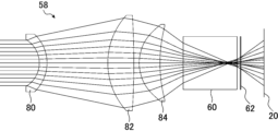
- FIG. 6 is a diagram conceptually showing an example of a condensing element.
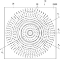
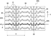
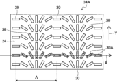
- FIG. 7 is a plan view conceptually showing an example of an optical element having a concentric liquid crystal orientation pattern.
- FIG. 8 is a schematic cross-sectional view of the optical element shown in FIG. 7.
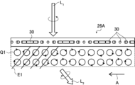
- FIG. 9 is a conceptual diagram for explaining the optical element shown in FIG. 7.
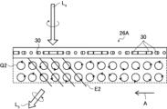
- FIG. 10 is a conceptual diagram for explaining the optical element shown in FIG. 7.
- FIG. 11 is a conceptual diagram for explaining the optical element shown in FIG. 7.
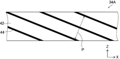
- FIG. 12 is a schematic cross-sectional view of another example of an optical element.
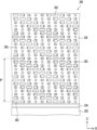
- 13 is a conceptual diagram for explaining the optical element shown in FIG. 12.
- FIG. 14 is a conceptual diagram for explaining the optical element shown in FIG. 12.
- FIG. 15 is a conceptual diagram for explaining the optical element shown in FIG. 12.
- FIG. FIG. 16 is a conceptual diagram for explaining a method of measuring the ratio of focal lengths.
- FIG. 16 is a conceptual diagram for explaining a method of measuring the ratio of focal lengths.
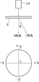
- FIG. 17 is a conceptual diagram for explaining a method of measuring the 0th-order light intensity.
- FIG. 18 is a conceptual diagram for explaining a method of measuring noise light intensity.
- FIG. 19 is a diagram conceptually showing another example of the optical element of the present invention.
- FIG. 20 is a diagram conceptually showing a condensing element in an embodiment of the present invention.
- FIG. 21 is a diagram conceptually showing a focal length profile of an optical element manufactured in a comparative example of the present invention.
- FIG. 22 is a conceptual diagram for explaining the direct drawing exposure method.
- FIG. 1 conceptually shows an example of the exposure system of the present invention.
- Exposure system 50 shown in FIG. also, in the exposure system 50, a beam expander element 70 and an optical path adjustment optical system 72 are provided between the light source 52 and the beam splitter element 54 as a preferred embodiment.
- the optical path adjusting optical system 72 is adjusting means in the present invention, detects the light beam M emitted from the light source 52, and adjusts the optical path of the light beam M. , detectors 78a and 78b.
- the focal length fL of the condensing element 58 in the present invention is defined as follows. As conceptually shown in FIG.
- the condensing element 58 has a distance Ds from the optical axis Oa in a direction orthogonal to the optical axis Oa of the condensing element 58 .
- ⁇ be the angle formed by a light beam parallel to the optical axis Oa, which is incident on the light collecting element 58 at a distance Ds from the optical axis Oa, and the optical axis Oa after passing through the light collecting element 58 .
- the focal length fG of the optical element may be measured by a method described later.
- the exposure system 50 in the illustrated example exposes the unexposed alignment film 24a containing a compound having a photo-alignment group, which serves as an alignment film (photo-alignment film) for aligning the liquid crystal compound, to form an alignment pattern. It is intended to form an alignment film having a That is, the exposure system 50 shown in FIG. 1 implements the method of forming a light distribution film of the present invention.
- the unexposed alignment film 24a containing a compound having a photo-alignment group is also referred to as "unexposed alignment film 24a" for convenience.
- an unexposed alignment film 24 a (an alignment film 24 to be described later) is supported by the substrate 20 .
- the exposure system 50 of the present invention is not limited to exposing the unexposed alignment film 24a as in the illustrated example. That is, the exposure system 50 of the present invention can be used to expose various known materials such as photosensitive materials (photosensitive materials).
- the exposure system 50 expands the diameter of the coherent light beam M emitted by the light source 52 by the beam expander element 70, splits it into mutually orthogonal linearly polarized light beams by the beam splitter element 54, and collects one of the linearly polarized light beams. After being collected by the optical element 58 , the two linearly polarized lights are superimposed by the beam combiner element 60 and converted to circularly polarized light by the polarization conversion element 62 .
- This exposure system 50 generates interference fringes by causing interference between two circularly polarized light beams with opposite rotating directions to be incident on the unexposed alignment film 24a, and exposes the unexposed alignment film 24a with the interference fringes. , to form an alignment pattern by an interference pattern on the unexposed alignment film 24a.
- the light beam M emitted by the light source 52 is adjusted by the optical path adjusting optical system 72 so that the optical path is appropriate before entering the beam expander element 70 .
- the optical path adjusting optical system 72 will be detailed later.
- both the beam expander element 70 and the optical path adjustment optical system 72 are provided as preferred embodiments. Therefore, the exposure system of the present invention may omit one of the beam expander element 70 and the optical path adjusting optical system 72, or omit both of them. That is, in the exposure system of the present invention, the light beam M emitted by the light source 52 may enter the beam expander element 70 directly. Alternatively, the light beam M emitted by the light source 52 may enter the beam splitter element 54 from the optical path adjusting optical system 72 . Alternatively, the light beam M emitted by the light source 52 may enter the beam splitter element 54 directly.
- a known light source can be used as the light source 52 as long as it can emit collimated light (parallel light) having coherence.
- a laser light source that emits collimated light and a combination of a laser light source that emits diffused light and a collimator lens are preferably used as light sources with particularly excellent coherence.
- the wavelength of the light beam M emitted by the light source 52 is not limited. Therefore, the light beam M emitted by the light source 52 may be ultraviolet light, visible light, or infrared light. When the light beam M is visible light, it may be monochromatic light, mixed light of two or more colors such as red light and blue light, or white light.
- the exposure system of the present invention is suitably used for exposure of a coating film (unexposed alignment film 24a) containing a compound having a photo-alignment group and serving as a photo-alignment film.
- the light beam M emitted by the light source 52 is preferably ultraviolet light, and more preferably light with a wavelength of 320 to 410 nm.
- a coherent light beam M emitted by the light source 52 enters the beam splitter element 54 via the optical path adjusting optical system 72 .
- the beam splitter element 54 splits the light beam M into a first light beam M1 and a second light beam M2, which are linearly polarized light beams orthogonal to each other.
- the first light beam M1 is S-polarized and the second light beam M2 is P-polarized.
- the beam splitter element 54 splits, for example, the incident coherent light beam M into a first S-polarized light beam M1 and a second P-polarized light beam M2.
- the first light beam M1 is the first light in the invention
- the second light beam M2 is the second light in the invention.
- terms such as "first" and "second" attached to light, members, etc. are attached for convenience in order to easily distinguish two (plural) things. It's a word and has no technical meaning.
- the beam splitter element 54 various known polarizing beam splitters such as cube type and plate type can be used as long as they can split the coherent light beam M into mutually orthogonal linearly polarized light beams. Also, as the beam splitter element 54, a combination of an optical element that splits the coherent light beam M, such as a half mirror and a non-polarizing beam splitter, and at least one polarizing element can be used. Light split by a half mirror, a non-polarizing beam splitter, or the like does not become linearly polarized light orthogonal to each other, but can be linearly polarized light orthogonal to each other by combining with a polarizing element.
- the polarizing element is not particularly limited, and various known ones such as a reflective polarizer such as a wire grid polarizer, an absorptive polarizing element having dichroism, and a polarizing prism such as a Glan-Thompson prism are suitable. can be used for
- the illustrated exposure system 50 preferably has a beam expander element (beam expansion element) between the light source 52 and the beam splitter element 54 for expanding the diameter of the light beam M.
- a beam expander element beam expansion element
- FIG. 1 By having the beam expander element in the exposure system 50, the exposure area in the unexposed alignment film 24a can be enlarged, and for example, the manufacture of a large optical element (liquid crystal diffraction lens) can be suitably handled. become.
- the beam expander element is not limited, and known beam expanders such as Keplerian beam expanders and Galilean beam expanders can be used as long as they can expand the diameter of the light beam M that is linearly polarized and has coherence. A variety of pandas are available.
- the position of beam expander element 70 is not restricted between light source 52 and beam splitter element 54 .
- beam expander element 70 may be placed in the optical path of first light beam M1 and the optical path of second light beam M2 between beam splitter element 54 and beam combiner element 60 .
- the beam expander element 70 is arranged upstream of the condensing element 58 .
- a plurality of beam expander elements 70 may be arranged in one optical path.
- beam expander element 70 may be positioned both upstream and downstream of beam splitter element 54 .
- upstream and downstream are upstream and downstream in the traveling direction of the light beam M from the light source 52 to the unexposed alignment film 24a.
- First light beam M 1 is reflected by mirror 56 a , collected by collector element 58 and incident on beam combiner element 60 . Therefore, the light transmitted through the condensing element 58 is condensed and expanded after the focal point.
- the condensing element 58 is the focal point changing condensing element in the present invention. That is, the condensing element 58 has a focal length that continuously changes in the plane, that is, in the direction orthogonal to the optical axis.
- the light-condensing element 58 has a ratio "fLmax/fLmin" between the maximum value fLmax and the minimum value fLmin of the focal length fL of 1.1. Super. This point will be described in detail later.
- the exposure system of the present invention which exposes the unexposed alignment film 24a with the interference light by interfering circularly polarized light with opposite rotation directions, uses such a condensing element 58 (focus changing condensing element). to expose the unexposed alignment film 24a.
- the exposure system of the present invention thereby produces the optical element (liquid crystal diffraction lens) of the present invention, which has a region in which the focal length (focal length fG) continuously changes in the plane, that is, in the direction perpendicular to the optical axis. can form an alignment film (photo-alignment film) capable of The condensing element 58 will be detailed later. Further, in the following description, the direction perpendicular to the optical axis of the condensing element 58 and various lenses is also referred to as "in-plane" for the sake of convenience.
- the second light beam M2 is reflected by the mirror 56b and enters the beam combiner element 60.
- the beam combiner element 60 has a first surface 60a that transmits at least a portion of the incident light and a second surface 60b that reflects at least a portion of the incident light.
- the light incident on the first surface 60 a of the beam combiner element 60 and transmitted therethrough and the light incident on the second surface 60 b of the beam combiner element 60 and reflected are superimposed and emitted from the beam combiner element 60 .
- the description of "at least a portion” in descriptions such as “transmit at least a portion of the incident light” and "reflect at least a portion of the incident light” omitted.
- the first light beam M1 condensed after passing through the condensing element 58 is incident on the first surface 60a of the beam combiner element 60 and is transmitted therethrough as parallel light (collimated light).
- a certain second light beam M2 is incident on the second surface 60b and reflected.
- the first light beam M1 incident on the first surface 60a and transmitted therethrough and the second light beam M2 incident on the second surface 60b and reflected are superimposed as shown in FIG.
- the first light beam M1 and the second light beam M2 are obtained by splitting the coherent light beam M which was originally the same. Therefore, the superimposed first light beam M1 and second light beam M2 interfere with each other.
- the beam combiner element 60 is not limited, and has a first surface 60a that transmits incident light and a second surface 60b that reflects incident light, and the light incident on and transmitted through the first surface 60a and the second surface 60b. Any known device can be used as long as it can superimpose the light reflected by the two surfaces 60b.
- the beam combiner element 60 for example, known beam splitters such as cube type and plate type, half mirrors, and the like can be used.
- the beam combiner element 60 may be a polarizing beam splitter or a non-polarizing beam splitter.
- the beam combiner element 60 preferably has the property of transmitting the first light beam M1 without changing its polarization state and reflecting the second light beam M2 without changing its polarization state.
- the first light beam M1 and the second light beam M2 superimposed by the beam combiner element 60 are then converted into circularly polarized light by the polarization conversion element 62 .
- the first light beam M1 and the second light beam M2 are linearly polarized lights orthogonal to each other. Therefore, the first light beam M1 and the second light beam M2 converted by the polarization conversion element 62 are, for example, the first light beam M1 is converted into right-handed circularly polarized light and the second light beam M2 is converted into left-handed circularly polarized light.
- the first light beam M1 is converted into left circularly polarized light and the second light beam M2 is converted into right circularly polarized light.
- the polarization conversion element 62 has a retardation in the plane direction (retardation Re, phase difference) of about 1/4 wavelength at the wavelengths of the incident light, that is, the first light beam M1 and the second light beam M2.
- a /4 wavelength plate (1/4 retardation plate, ⁇ /4 plate) is preferably exemplified.
- a quarter-wave plate having a ratio of retardation to wavelength in the plane direction of 0.24 to 0.26 is preferably exemplified, and is 0.245 to 0.255.
- a quarter-wave plate is more preferably exemplified.
- the polarization conversion element 62 may be a combination of a plurality of optical elements. In this case, the total retardation of the individual optical elements of the plurality of optical elements forming the polarization conversion element 62 should be about 1/4 wavelength.
- the polarization conversion element 62 used in the present invention is not particularly limited. Therefore, the polarization conversion element 62 may be, for example, a layer formed from a composition containing a liquid crystal compound, or a polymer film (a film formed from a polymer (resin), particularly a film that has been stretched). It may be a layer formed from a polymer film).
- Polymer films include polycarbonate films, cycloolefin polymer films, TAC films, polyimide films, and the like. A cycloolefin polymer film is particularly preferable from the viewpoint of being excellent in light resistance and enduring long-term use.
- each layer of the laminated wave plate may be made of different materials independently.
- the polarization conversion element 62 used in the present invention is preferably a layer formed from a composition containing a liquid crystal compound.
- a composition containing a liquid crystal compound is preferably a composition containing a polymerizable liquid crystal compound.
- the layer formed from a composition containing a polymerizable liquid crystal compound is preferably a layer formed by fixing a polymerizable liquid crystal compound by polymerization or the like.
- the type of liquid crystal compound is not particularly limited. Liquid crystal compounds can be classified into rod-like liquid crystal compounds and discotic liquid crystal compounds (discotic liquid crystal compounds) according to their shapes. Furthermore, each liquid crystal compound has a low-molecular-weight type and a high-molecular-weight type. Polymers generally refer to those having a degree of polymerization of 100 or more (Polymer Physics: Phase Transition Dynamics, Masao Doi, p. 2, Iwanami Shoten, 1992). Any liquid crystal compound can be used in the present invention. In the liquid crystal composition, two or more types of rod-like liquid crystal compounds, two or more types of discotic liquid crystal compounds, mixtures of rod-like liquid crystal compounds and discotic liquid crystal compounds, and the like may be used.
- rod-like liquid crystal compound for example, those described in claim 1 of JP-A-11-513019 and paragraphs [0026] to [0098] of JP-A-2005-289980 are preferably used. can be done.
- discotic liquid crystal for example, those described in paragraphs [0020] to [0067] of JP-A-2007-108732 and paragraphs [0013] to [0108] of JP-A-2010-244038 can be preferably used.
- the position of the polarization conversion element 62 is not limited to downstream of the beam combiner element 60 in the illustrated example.
- the polarization conversion element 62 is not downstream of the beam combiner element 60, but instead is the optical path of the first light beam M1 from the beam splitter element 54 to the beam combiner element 60 and the second light beam M1 from the beam splitter element 54 to the beam combiner element 60. It may be arranged in the optical path of the two light beams M2.
- the polarization conversion element 62 is arranged upstream of the beam combiner element 60, circularly polarized light with the same rotation direction is made incident on the first surface 60a and the second surface 60b of the beam combiner element 60.
- the exposure system 50 exposes the unexposed alignment film 24a by generating interference fringes by interfering two circularly polarized light beams with opposite rotating directions to be incident on the unexposed alignment film 24a. to form an interference pattern, that is, an alignment pattern on the unexposed alignment film 24a.
- the alignment pattern formed on the unexposed alignment film 24 a is changed by the condensing element 58 .
- the orientation pattern to be formed on the unexposed orientation film 24a can be selected by selecting the condensing element 58 to be used.
- the exposure system 50 of the present invention uses a condensing element 58 which is a focal point changing condensing element having a focal length that continuously changes in the plane, that is, in the direction orthogonal to the optical axis. That is, the focal length of the condensing element 58 continuously changes in the plane in the direction away from the optical axis.
- a condensing element 58 which is a focal point changing condensing element having a focal length that continuously changes in the plane, that is, in the direction orthogonal to the optical axis. That is, the focal length of the condensing element 58 continuously changes in the plane in the direction away from the optical axis.
- a positive lens is normally used as a condensing element.
- the positive lens used in this exposure system usually has a constant focal length in the plane, that is, in the direction perpendicular to the optical axis.
- the condensing element is a positive lens
- the alignment pattern formed in the unexposed alignment film 24a by the exposure system will have short straight lines, as conceptually shown in FIG.
- the orientation pattern has radially varying patterns while continuously rotating in one direction, as indicated by the arrows in the figure.
- the orientation pattern formed on the unexposed orientation film 24a by the exposure system 50 is a short straight line that changes while continuously rotating, as shown in FIG. It is a concentric circular orientation pattern having one direction to be concentrically directed from the inside to the outside. That is, this alignment pattern is a pattern having concentric circles formed by short straight lines in the same direction.
- the polarization state of the light with which the unexposed alignment film 24a is irradiated changes periodically in the form of interference fringes.
- the first light beam M1 is condensed by a condensing element (positive lens) and diffused after the focal point. Therefore, the intersecting state of the left-handed circularly polarized light and the right-handed circularly polarized light changes from the inner side to the outer side of the concentric circle. As a result, an orientation pattern is obtained in which the period becomes shorter from the inside to the outside.
- the short straight lines extend outward from the center in a number of directions , e.g. It changes while continuously rotating along the indicated directions.
- a short straight line whose orientation changes while rotating is also referred to as a "short line" for the sake of convenience.
- the direction of rotation of the short line is the same in all directions (one direction). In the illustrated example, the direction of rotation of the short line is counterclockwise in all the directions indicated by arrow A1 , the direction indicated by arrow A2 , the direction indicated by arrow A3 , and the direction indicated by arrow A4 . .
- the direction of rotation of the short lines is reversed at the center on this straight line.
- a straight line formed by arrows A1 and A4 is directed to the right in the drawing (direction of arrow A1 ).
- the short line first rotates clockwise from the outside toward the center, reverses the direction of rotation at the center, and then rotates counterclockwise from the center toward the outside.
- the length of one period ⁇ is inside gradually shortens outward.
- the condensing element when a positive lens with a constant in-plane focal length is used as the condensing element, the decrease of one period ⁇ from the inside to the outside monotonically decreases in inverse proportion.
- the obtained optical element has an in-plane focal length as conceptually shown in FIG. Acts as a constant condensing lens.
- the horizontal axis is the optical axis, that is, the distance from the center, and the vertical axis is the focal length.
- the shorter the period ⁇ the greater the diffraction in the optical element, resulting in a shorter focal length.
- the exposure system 50 of the present invention exposure is performed using such interference light.
- a condensing element 58 whose focal length changes continuously in the direction of light is used.
- the exposure system 50 of the present invention can vary the degree of decrease of one period ⁇ in the concentric alignment pattern, including an increase instead of an inversely proportional monotonic decrease.
- the region in which the length of one period ⁇ in the orientation pattern increases may or may not be included. Therefore, by fabricating an optical element using an alignment film having such an alignment pattern, it is possible to obtain an optical element having a region in which the focal length continuously changes in the plane, that is, in the direction perpendicular to the optical axis. Specifically, this optical element has a region in which the focal length continuously changes in the outward direction from the center of the concentric circles in the alignment pattern.
- the unexposed alignment film 24a is exposed using a condensing element 58 having a focal length profile conceptually shown on the left side of FIG. 5, it is possible to fabricate an optical element having a focal length profile having a region in which the focal length continuously changes in the direction away from the optical axis in the plane.
- the focal length profile is specifically a change in focal length in the plane of an optical element such as a lens according to the distance from the optical axis. Therefore, as before, in FIG. 5, the horizontal axis is the distance from the optical axis and the vertical axis is the focal length. Therefore, a general optical element having a constant in-plane focal length as described above has a laterally straight focal length profile as shown in FIG. 4 described above.
- an alignment film from which an optical element having an area in which the focal length changes continuously without having a boundary area or the like can be obtained. It can be formed by sex.
- the light collecting element 58 has a continuously varying focal length in-plane, ie, in a direction perpendicular to the optical axis.
- the focal length profile of the light collecting element 58 is not limited.
- the orientation pattern (interference pattern) of the orientation film formed by the exposure system 50 that is, the focal length profile of the optical element is basically determined by the focal length profile of the condensing element 58 . Therefore, the focal length profile of the condensing element 58 can be appropriately set by design, simulation, etc., according to the focal length profile of the target optical element, so that an optical element having this focal length profile can be obtained. good.
- the light collection element 58 preferably has one or more extrema in the focal length profile.
- the extrema in the focal length profile are the point at which the focal length changes from decreasing to increasing (maximum) and the point at which the focal length changes from increasing to decreasing (minimum).
- Having one or more extrema in the focal length profile of the light collection element 58 allows for the formation of an orientation pattern that can produce optical elements with complex variations in the focal length profile. More preferably, the number of extrema in the focal length profile of the condensing element 58 is two or more.
- the condensing element 58 is a focal length changing condensing element having a focal length profile in which the focal length continuously changes.
- the ratio "fLmax/fLmin" between the value fLmax and the minimum value fLmin is greater than 1.1.
- the condensing element 58 is a lens (optical lens)
- the condensing element 58 is a condensing element described below. That is, as conceptually shown in FIG. 2, the distance from the optical axis Oa of the condensing element 58 in the direction perpendicular to the optical axis Oa is defined as the distance Ds.
- ⁇ be the angle formed by a light beam parallel to the optical axis Oa, which is incident on the light collecting element 58 at a distance Ds from the optical axis Oa, and the optical axis Oa after passing through the light collecting element 58 .
- the condensing element 58 is a lens, it is a focal point changing condensing element in which the focal length fL defined in this manner changes continuously in the direction perpendicular to the optical axis Os.
- the focal length fL of the condensing element 58 defined in this way has a maximum value fLmax and a minimum value fLmin. >1.
- the ratio "fLmax/fLmin” is less than 1.1, problems such as failure to form an alignment film corresponding to an optical element having a sufficient change in focal length profile occur.
- the ratio "fLmax/fLmin” is preferably 1.2 or more, more preferably 1.3 or more, in order to suitably liquidize an alignment film corresponding to an optical element having a sufficient change in focal length profile.
- the upper limit of the ratio "fLmax/fLmin” is not limited, it is preferably 200 or less, and more preferably 100 or less, in consideration of the difficulty of design, production of the condensing element, and production of the optical element.
- the condensing element 58 is not limited, and various optical elements can be used as long as they satisfy the above conditions.
- the condensing element 58 preferably has a plurality of lenses.
- the condensing element 58 preferably has at least one of an aspheric lens and a cylinder lens (cylindrical lens).
- an aspheric lens and a cylinder lens (cylindrical lens).
- a condensing element 58 combining a negative meniscus lens 80, both positive lenses 82 having different curvatures, and a positive meniscus lens 84 having an aspherical surface is exemplified.
- the present invention also utilizes a method of obtaining a non-axisymmetric focal length profile in the light-collecting element 58 by using a cylinder lens as the light-collecting element 58 or by including a cylinder lens in the light-collecting element 58. It is possible. Further, in the present invention, the focal length profile of the condensing element 58 is made non-axisymmetric by a method in which the optical axis of the positive lens serving as the condensing element is tilted with respect to the traveling direction of the first light beam M1. A method is also available.
- the surface (exposed surface) of the unexposed alignment film 24a is tilted with respect to the optical axis of the positive lens serving as the light-condensing element, so that the focal length profile of the light-condensing element 58 is non-axial.
- Symmetrical methods are also available.
- a method of making the focal length profile of the condensing element 58 non-axisymmetric by making the traveling direction of the second light beam M2 inclined with respect to the incident surface of the beam combiner element 60 can also be used. Two or more of the above methods may be used in combination.
- the unexposed alignment film 24a may be positioned downstream or upstream of the focal point of the condensing element 58 .
- a space for arranging the beam combiner element 60, the polarization conversion element 62 and the like can be secured between the condensing element 58 and the object to be irradiated.
- the exposure system 50 can be miniaturized.
- the condensing element 58 is arranged only in the optical path of the first light beam M1 passing through the first surface 60a of the beam combiner element 60, but the present invention is not limited thereto. . That is, the condensing element 58 may be arranged only in the optical path of the second light beam M2 reflected by the second surface 60b of the beam combiner element 60, and may be arranged in the optical path of the first light beam M1 and the second light beam M2. Condensing elements 58 may be placed in both optical paths.
- the condensing element 58 is arranged in both the optical path of the first light beam M1 and the optical path of the second light beam M2, the optical path of the first light beam M1 and the optical path of the second light beam M2 are different.
- a condensing element 58 is arranged.
- an orientation pattern is formed by interference of two spherical waves, so the degree of freedom of the orientation pattern can be increased.
- condensing elements are arranged in both the optical path of the first light beam M1 and the optical path of the second light beam M2, one of them is the condensing element 58, that is, the focal point changing condensing element of the present invention, and the other is A normal positive lens whose focal length does not change in the plane may be used.
- the arrangement position of the condensing element 58 is not limited to the upstream of the beam combiner element 60, and various positions can be used. In this case, a plurality of condensing elements 58 may be arranged. As an example, after providing a condensing element 58 in at least one of the optical path of the first light beam M1 and the optical path of the second light beam M2, further, between the beam combiner element 60 and the polarization conversion element 62, a light condensing element An element 58 may be placed.
- the first light beam M1 is condensed by the condensing element 58 and diffused after the focal point. That is, a part of the first light beam M1 emitted from the beam combiner element 60 has an angle with respect to the optical axis.
- the alignment pattern is formed on the unexposed alignment film 24a.
- the direction perpendicular to the main surface of the unexposed alignment film 24a that is, the normal direction is 0°
- the larger the angle of the first light beam M1 incident on the unexposed alignment film 24a the finer the grains.
- An interference pattern can be obtained.
- the pattern shown in FIG. 3 is such that short lines change while continuously rotating in one direction, the first light beam M1 incident on the unexposed alignment film 24a has a wide angle. The more, the shorter the period .LAMBDA. in which the short line rotates 180.degree. in one direction (the direction of the arrow).
- the main surface is the maximum surface of the sheet-like material (film, layer, plate-like material, membrane).
- the angle of the light transmitted through the light collecting element 58 and exiting the beam combiner element 60 with respect to the optical axis there is no limit to the angle of the light transmitted through the light collecting element 58 and exiting the beam combiner element 60 with respect to the optical axis.
- at least a part of the light that has passed through the condensing element 58 (the first light beam M1 in the illustrated example) is emitted from the beam combiner element 60 when parallel light is incident on the condensing element 58.
- An angle of 15° or more with respect to the optical axis is preferred.
- the maximum angle of the light emitted from the beam combiner element 60 with respect to the optical axis is more preferably 17° or more, and even more preferably 20° or more.
- a fine interference pattern can be formed by having at least part of the light emitted from the beam combiner element 60 at an angle of 15° or more with respect to the optical axis.
- a fine interference pattern can be preferably formed.
- the intensity of light applied to the unexposed alignment film 24a is uniform within the plane of the unexposed alignment film 24a.
- the light intensity is the ratio of the maximum value/minimum value of the light intensity in the plane (direction orthogonal to the optical axis) on the exposure surface of the medium to be exposed. , 25 times or less.
- the intensity of the light on the surface of the unexposed alignment film 24a is preferably 25 times or less in terms of the maximum/minimum ratio.
- the intensity of light in this case is illuminance. Having such a configuration is preferable in that the accuracy of exposure of the unexposed alignment film 24a can be improved.
- the maximum/minimum ratio of the intensity of light within the exposed surface of the medium to be exposed is more preferably 10 times or less, more preferably 5 times or less, and most preferably 1, that is, uniform intensity over the entire surface.
- the optical path length from the light source 52 to the unexposed alignment film 24a is not limited, but the optical path length between the beam splitter element 54 and the beam combiner element 60 is 800 mm or less. is preferred. Such a configuration is preferable in that the exposure system 50 can be miniaturized, and deterioration in exposure precision caused by air fluctuations and other vibrations can be suppressed.
- the optical path length between beam splitter element 54 and beam combiner element 60 is more preferably 600 mm or less, and even more preferably 400 mm or less.
- the light reflected by the surfaces of the optical elements that make up the exposure system 50 becomes noise and lowers the exposure accuracy of the unexposed alignment film 24a.
- at least one optical element of the optical members that make up the exposure system 50 more preferably more optical elements, and even more preferably the beam expander element 70 is included in the beam expander element 70 .
- All downstream optical elements, particularly preferably all optical elements have a surface reflectance of 0.5% or less for light of the wavelength emitted by the light source 52 .
- the surface having a surface reflectance of 0.5% or less may be at least one surface, but preferably both the light entrance surface and the light exit surface.
- the surface reflectance of the optical member is more preferably 0.3% or less, and even more preferably 0.2% or less.
- the method for making the surface reflectance of the optical member there are no restrictions on the method for making the surface reflectance of the optical member 0.5% or less, and various known methods can be used. Examples include a method of providing an AR (Anti Reflection) layer (AR film) on the surface, a method of providing a moth-eye layer (moth-eye film) on the surface, and the like.
- AR Anti Reflection
- moth-eye film moth-eye layer
- the exposure system 50 of the illustrated example detects the light beam M emitted by the light source 52 upstream of the beam expander element 70 between the light source 52 and the beam expander element 70 to detect the light beam M It has an optical path adjusting optical system 72 that adjusts the optical path (optical axis) of M.
- optical path adjustment optics 72 includes actuation mirrors 74a and 74b, mirror 76, and detectors 78a and 78b.
- the working mirror and 74b are known variable angle mirrors whose angles can be adjusted by actuators such as piezo elements.
- the detector 78a is a detector that detects the incident position of the light beam M on the operating mirror 74a.
- the detector 78 b is a detector that detects the incident position of the light beam M on the mirror 76 .
- various known methods such as a method of detecting light transmitted through the operating mirrors 74a and 76 with a diode detector can be used.
- Mirror 76 is a known reflective mirror.
- the optical path adjusting optical system 72 detects the incident position of the light beam M on the working mirror 74a by the detector 78a and detects the incident position of the light beam M on the mirror 76 by the detector 78b during the exposure of the unexposed alignment film 24a. The incident position of the light beam M is detected.
- the optical path adjustment optical system 72 adjusts the angles of the working mirrors 74a and 74b according to the detection result of the light beam M so that the optical path of the light beam M from the light source 52 to the beam expander element 70 is appropriate. Adjust.
- the light source 52 fluctuates over time, causing the optical path of the light beam to shift.
- the incident position of the interference light on the unexposed alignment film 24a is shifted, and the exposure position on the unexposed alignment film 24a is different from the intended position.
- the position and angle of incidence of the light beam M on each optical element are shifted. If the incident position and angle of incidence on the optical elements are deviated, each optical element cannot exhibit a predetermined optical performance, and the exposure accuracy of the unexposed alignment film 24a is lowered.
- the exposure system 50 of the illustrated example preferably has an optical path adjusting optical system 72 that adjusts the optical path of the light beam M, so that the optical path of the light beam M is set at an appropriate position and the unexposed alignment film is exposed. 24a exposure can be performed. As a result, the exposure system 50 can perform high-precision exposure on the target position of the unexposed alignment film 24a.
- the optical path adjusting optical system is not limited to the configuration shown in the drawings, and various known automatic optical path adjusting means for light beams used in various optical systems (optical devices) can be used. , is available.
- various known automatic optical path adjusting means for light beams used in various optical systems can be used.
- the beam splitter element 54 not upstream of the beam splitter element 54 as in the illustrated example, but downstream of the beam combiner element 60, interference fringes due to interference light between the first light beam M1 and the second light beam M2 are detected.
- Means for adjusting the optical paths of the first light beam M1 and/or the second light beam M2 so as to obtain appropriate interference fringes according to the detection result of are exemplified.
- the interference fringes are detected downstream of the polarization conversion element 62, and the angles of the mirror 56a and/or the mirror 56b are adjusted so that appropriate interference fringes are obtained, and the first light beams M1 and/or Alternatively, a method of adjusting the optical path of the second light beam M2 is exemplified.
- this light beam optical path adjusting means interference fringes can be detected by placing the imaging element so that the imaging surface is on the exposure surface. Further, only one of these light beam optical path adjusting means may be used, or a plurality of adjusting means may be used together.
- the unexposed alignment film 24a is a coating film containing a compound having a photo-alignment group. That is, the exposure system 50 shown in FIG. 1 implements the alignment film forming method of the present invention, in which a coating film containing a compound having a photoalignment group is exposed with the exposure system of the present invention.
- the unexposed alignment film 24a that is, the alignment film 24 is supported by the substrate 20 (see FIG. 8). That is, in the method of forming an alignment film of the present invention shown in FIG. 1, as an example, an unexposed alignment film 24a is formed on the substrate 20, and the unexposed alignment film 24a is exposed by the exposure system 50 of the present invention. By doing so, an alignment film 24 made of a photo-alignment film is formed.
- Various sheet materials can be used as the substrate 20 as long as it can support the unexposed alignment film 24a, that is, the alignment film 24, and an optically anisotropic layer 26, which will be described later.
- a transparent support is preferable, and a polyacrylic resin film such as polymethyl methacrylate, a cellulose resin film such as cellulose triacetate, a cycloolefin polymer film (for example, the product name "Arton” manufactured by JSR Corporation, a commercial product name "Zeonor", manufactured by Nippon Zeon Co., Ltd.), polyethylene terephthalate (PET), polycarbonate, and polyvinyl chloride.
- the support is not limited to a flexible film, and may be a non-flexible substrate such as a glass substrate.
- a coating film containing a compound having a photo-alignment group is formed on the surface of the substrate 20, and the coating film is dried to form an unexposed alignment film 24a.
- the dried coating film is irradiated with interference light formed by the above-described exposure system 50 of the present invention, in which the first circularly polarized light beam M1 and the second circularly polarized light beam M2 are overlapped.
- the unexposed alignment film 24a is exposed with an interference pattern, that is, an alignment pattern to form an alignment pattern, thereby forming an alignment film 24 having a concentric alignment pattern.
- the degree of decrease of one period ⁇ in the direction outward from the center of the concentric circles is not an inversely proportional monotonic decrease, but varies, including an increase, according to the focal length profile of the condensing element 58. is as described above.
- Photo-alignment materials used in the photo-alignment film for example, JP-A-2006-285197, JP-A-2007-76839, JP-A-2007- 138138, JP 2007-94071, JP 2007-121721, JP 2007-140465, JP 2007-156439, JP 2007-133184, JP 2009-109831 Publication, the azo compound described in Patent No. 3883848 and Patent No.
- an optical element of the present invention a composition containing a liquid crystal compound is applied to the alignment film thus formed, dried, and, if necessary, the liquid crystal compound is cured.
- an optical element liquid crystal diffraction lens having a concentric liquid crystal orientation pattern as described above can be produced.
- FIG. 7 and 8 show an optical element in which an optically anisotropic layer 26 is formed on the alignment film 24 having the alignment pattern shown in FIG.
- An example of is conceptually shown.
- 7 is a plan view conceptually showing the optical element
- FIG. 8 is a sectional view conceptually showing the optical element.
- the optical element 10 shown in FIGS. 7 and 8 has an optically anisotropic layer 26 which is a liquid crystal layer formed using a composition containing a liquid crystal compound on an alignment film 24 .
- the orientation film 24 has an orientation pattern in which the directions of the short lines change while continuously rotating in one direction, radially from the inside to the outside. , which have a concentric circular orientation pattern.
- the liquid crystal alignment pattern in the optically anisotropic layer 26 follows the alignment pattern formed in the alignment film 24 (unexposed alignment film 24a). Specifically, the liquid crystal compound 30 is oriented with its longitudinal direction aligned with the longitudinal direction of the single lines in the alignment pattern of the alignment film 24 . Therefore, in the optically anisotropic layer 26 formed using a composition containing a liquid crystal compound, which is formed on such an alignment film 24, the direction of the optical axis derived from the liquid crystal compound 30 is unidirectional. It has a liquid crystal alignment pattern that changes while continuously rotating toward the outside radially from the inside to the outside. That is, the liquid crystal alignment pattern of the optically anisotropic layer 26 shown in FIGS.
- FIG. 7 and 8 has a concentric circular pattern in which the direction of the optical axis derived from the liquid crystal compound 30 changes while continuously rotating from the inside to the outside. is a pattern of concentric circles in 7 to 15 (except FIG. 14) exemplify a rod-like liquid crystal compound as the liquid crystal compound 30, so the direction of the optic axis coincides with the longitudinal direction of the liquid crystal compound 30.
- FIG. 14 is a pattern of concentric circles in 7 to 15 (except FIG. 14) exemplify a rod-like liquid crystal compound as the liquid crystal compound 30, so the direction of the optic axis coincides with the longitudinal direction of the liquid crystal compound 30.
- the orientation of the optic axis of the liquid crystal compound 30 is in a number of directions outward from the center of the optically anisotropic layer 26, for example, the direction indicated by arrow A1 , the direction indicated by arrow A It changes while continuously rotating along the direction indicated by 2 , the direction indicated by arrow A3 , the direction indicated by arrow A4 , and so on. Therefore, in the optically anisotropic layer 26, the rotation direction of the optic axis of the liquid crystal compound 30 is the same in all directions (one direction).
- the direction of rotation of the optic axis of the liquid crystal compound 30 in all the directions indicated by arrow A1 , the direction indicated by arrow A2 , the direction indicated by arrow A3 , and the direction indicated by arrow A4 is counterclockwise. That is, if the arrows A 1 and A 4 are regarded as one straight line, the direction of rotation of the optical axis of the liquid crystal compound 30 is reversed at the center of the optically anisotropic layer 26 on this straight line. As an example, it is assumed that a straight line formed by arrows A1 and A4 is directed to the right in the drawing (direction of arrow A1 ).
- the optic axis of the liquid crystal compound 30 initially rotates clockwise from the outer direction toward the center of the optically anisotropic layer 26, and the direction of rotation is reversed at the center of the optically anisotropic layer 26. , and then rotate counterclockwise outward from the center of the optically anisotropic layer 26 .
- the liquid crystal alignment pattern is such that the direction of the optic axis derived from the liquid crystal compound in one direction in which the direction of the optic axis of the liquid crystal compound 30 changes while rotating continuously.
- the length of 180° rotation is defined as one cycle, the length of one cycle gradually decreases from the inside to the outside.
- the alignment film 24 shown in FIG. 3 has an alignment pattern formed by an exposure system using a normal positive lens as a condensing element. Towards the outside, it monotonically decreases inversely proportionally.
- the exposure system 50 of the present invention uses a light collecting element 58 (focal change light collecting element) having a focal length that continuously changes in the direction perpendicular to the optical axis.
- the degree of decrease in one period ⁇ in the concentric alignment pattern is not an inversely proportional monotonous decrease, but includes an increase. fluctuating. Therefore, although not shown in FIG. 7, the length of one period of the optically anisotropic layer 26 formed on the alignment film 24 also fluctuates, including an increase instead of a monotonous decrease from the inside to the outside. .
- the region where the length of one cycle in the liquid crystal alignment pattern increases may or may not be included. For example, in the case of an optical element having a focal length profile as shown on the right side of FIG.
- the degree of reduction in the length of one period varies from the inside to the outside according to this focal length profile. , and also has regions where the length of one period increases.
- the optically anisotropic layer described below, even the optically anisotropic layer 26 produced by the manufacturing method of the present invention, in which the degree of reduction in the length of one period varies, It is the same as the ordinary optically anisotropic layer 23 whose thickness monotonously decreases.
- Circularly polarized light incident on the optically anisotropic layer 26 having this liquid crystal orientation pattern changes its absolute phase in individual local regions where the directions of the optical axes of the liquid crystal compound 30 are different. At this time, the amount of change in each absolute phase differs according to the direction of the optical axis of the liquid crystal compound 30 on which the circularly polarized light is incident.
- the optically anisotropic layer optical element 10 having a liquid crystal alignment pattern in which the direction of the optic axis of the liquid crystal compound 30 changes while continuously rotating in one direction
- the diffraction direction of the transmitted light is determined by the direction of the liquid crystal compound. 30 depends on the direction of rotation of the optical axis.
- the optically anisotropic layer 26 having such a concentric liquid crystal alignment pattern that is, a liquid crystal alignment pattern in which the optic axis rotates continuously and changes radially, is formed in the direction of rotation of the optic axis of the liquid crystal compound 30 and Depending on the direction of rotation of the incident circularly polarized light, the incident light (light beam) can be transmitted divergingly or convergingly.
- the optically anisotropic layer 26 is formed using a composition containing a liquid crystal compound.
- the optically anisotropic layer 26 only covers the liquid crystal compound 30 (liquid crystal compound molecules) on the surface of the alignment film 24. showing.
- the optically anisotropic layer 26, as conceptually shown in FIG. It has a stacked structure.
- the optically anisotropic layer 26 functions as a general ⁇ /2 plate when the value of in-plane retardation (retardation in the plane direction) is set to ⁇ /2. It has the function of giving a phase difference of half a wavelength, that is, 180° to two mutually orthogonal linearly polarized light components contained in incident light.
- the direction of the optic axis derived from the liquid crystal compound continuously rotates in one direction (directions of arrows A 1 to A 4 in FIG. 7, etc.) in the plane of the optically anisotropic layer. It has a liquid crystal alignment pattern that changes radially from the inside to the outside.
- the optical axis 30A derived from the liquid crystal compound 30 is an axis with the highest refractive index in the liquid crystal compound 30, a so-called slow axis.
- the optic axis 30A is along the long axis direction of the rod shape.
- the optic axis 30A derived from the liquid crystal compound 30 is also referred to as "the optic axis 30A of the liquid crystal compound 30" or "the optic axis 30A".
- the optically anisotropic layer 26 has an optically anisotropic layer 26 having a liquid crystal orientation pattern that changes while the optic axis 30A continuously rotates in one direction indicated by an arrow A, the plan view of which is conceptually shown in FIG. Reference is made to layer 26A. Even in the concentric liquid crystal orientation pattern having one direction in which the optical axis changes while continuously rotating as shown in FIG. , the same optical effects as those of the liquid crystal alignment pattern shown in FIG. 9 are exhibited.
- the liquid crystal compound 30 is two-dimensionally aligned in a plane parallel to one direction indicated by arrow A and the Y direction perpendicular to the arrow A direction. 7 and 8, which will be described later, the Y direction is a direction perpendicular to the plane of the paper. In the following description, "one direction indicated by arrow A” is also simply referred to as "arrow A direction”.
- the circumferential direction of concentric circles in the concentric liquid crystal alignment pattern corresponds to the Y direction in FIG.
- the optically anisotropic layer 26A has a liquid crystal orientation pattern in which the direction of the optical axis 30A derived from the liquid crystal compound 30 changes while continuously rotating along the arrow A direction in the plane of the optically anisotropic layer 26A. have. That the direction of the optical axis 30A of the liquid crystal compound 30 changes while continuously rotating in the direction of the arrow A (predetermined one direction) specifically means that the liquid crystal compounds arranged along the direction of the arrow A.
- the angle formed by the optical axis 30A of 30 and the direction of the arrow A varies depending on the position in the direction of the arrow A. This means that the angle changes sequentially up to ⁇ 180°.
- the difference in angle between the optical axes 30A of the liquid crystal compounds 30 adjacent to each other in the direction of the arrow A is preferably 45° or less, more preferably 15° or less, and even more preferably a smaller angle. .
- the direction of the optic axis 30A is Equivalent liquid crystal compounds 30 are arranged at regular intervals.
- the angle between the direction of the optical axis 30A and the direction of the arrow A is the same between the liquid crystal compounds 30 arranged in the Y direction.
- areas having the same direction of the optical axis 30A are formed in circular rings with the same center, forming a concentric liquid crystal alignment pattern.
- the length by which the optic axis 30A of the liquid crystal compound 30 rotates 180° ( distance) is the length ⁇ of one period in the liquid crystal alignment pattern. That is, in the case of the optically anisotropic layer 26A shown in FIG. 9, the optic axis 30A of the liquid crystal compound 30 rotates 180° in the direction of the arrow A in which the direction of the optic axis 30A continuously rotates and changes within the plane.
- the length (distance) is one period ⁇ in the liquid crystal alignment pattern.
- one period ⁇ in the liquid crystal alignment pattern is defined by the distance from ⁇ to ⁇ +180° formed by the optical axis 30A of the liquid crystal compound 30 and the direction of the arrow A. That is, the distance between the centers in the direction of arrow A of two liquid crystal compounds 30 having the same angle with respect to the direction of arrow A is one period ⁇ . Specifically, as shown in FIG. 9, the distance between the centers in the direction of arrow A of two liquid crystal compounds 30 whose direction of arrow A coincides with the direction of the optical axis 30A is one period ⁇ .
- the liquid crystal orientation pattern of the optically anisotropic layer is changed by continuously rotating the direction of the arrow A, that is, the direction of the optical axis 30A, in this one period ⁇ .
- the optical element 10 is also a transmissive liquid crystal diffraction element (liquid crystal diffraction lens), and this one period ⁇ is the period (one period) of the diffraction structure.
- one period ⁇ in the optically anisotropic layer 26 is It is as described above that it gradually becomes shorter toward the outside.
- the liquid crystal compounds arranged in the Y direction have an equal angle between the optical axis 30A and the direction of arrow A (one direction in which the optical axis of the liquid crystal compound 30 rotates).
- a region R is defined as a region where the liquid crystal compound 30 having the same angle formed by the optical axis 30A and the arrow A direction is arranged in the Y direction.
- the value of in-plane retardation (Re) in each region R is preferably half a wavelength, ie, ⁇ /2.
- the refractive index difference associated with the refractive index anisotropy of the region R in the optically anisotropic layer is the refractive index in the direction of the slow axis in the plane of the region R and the direction orthogonal to the direction of the slow axis is the refractive index difference defined by the difference from the refractive index of That is, the refractive index difference ⁇ n associated with the refractive index anisotropy of the region R is the difference between the refractive index of the liquid crystal compound 30 in the direction of the optical axis 30A and the refractive index of the liquid crystal compound 30 in the direction perpendicular to the optical axis 30A in the plane of the region R.
- the refractive index difference ⁇ n is equal to the refractive index difference of the liquid crystal compound.
- the optical axes 30A formed in a circular ring shape with the same center are in the same direction.
- the area corresponds to area R in FIG. This is the same for the reflective optical element 36 having a cholesteric liquid crystal layer, which will be described later.
- FIGS. 10 and 11 When circularly polarized light is incident on such an optically anisotropic layer 26A, the light is diffracted and the direction of the circularly polarized light is changed.
- This action is conceptually shown in FIGS. 10 and 11.
- FIG. Assume that the optically anisotropic layer 26A has a product value of ⁇ /2 between the refractive index difference of the liquid crystal compound and the thickness of the optically anisotropic layer. As described above, this effect is exactly the same in the optical element 10 radially having the liquid crystal alignment pattern in which the optical axis 30A continuously rotates in one direction.
- the optically anisotropic layer 26 has a left circular shape.
- the incident light L 1 is given a phase difference of 180° by passing through the optically anisotropic layer 26A, and the transmitted light L 2 is converted into right-handed circularly polarized light.
- the absolute phase of the incident light L 1 changes according to the direction of the optical axis 30A of each liquid crystal compound 30 when passing through the optically anisotropic layer 26A.
- the direction of the optical axis 30A changes while rotating along the direction of the arrow A, the amount of change in the absolute phase of the incident light L1 differs depending on the direction of the optical axis 30A.
- the liquid crystal alignment pattern formed on the optically anisotropic layer 26A is a periodic pattern in the direction of the arrow A, the incident light L 1 passing through the optically anisotropic layer 26 has a pattern as shown in FIG. , a periodic absolute phase Q1 is given in the direction of arrow A corresponding to the direction of each optical axis 30A.
- an equiphase plane E1 inclined in the direction opposite to the arrow A direction is formed.
- the transmitted light L2 is diffracted so as to be inclined in a direction perpendicular to the equal phase plane E1, and travels in a direction different from the traveling direction of the incident light L1 .
- the left-handed circularly polarized incident light L 1 is converted into right-handed circularly polarized transmitted light L 2 , which is inclined in the direction of arrow A by a certain angle with respect to the incident direction.
- the direction of the optical axis 30A changes while rotating along the direction of the arrow A, the amount of change in the absolute phase of the incident light L4 differs according to the direction of the optical axis 30A. Furthermore, since the liquid crystal alignment pattern formed on the optically anisotropic layer 26A is a periodic pattern in the direction of the arrow A, the incident light L 4 that has passed through the optically anisotropic layer 26 has a , a periodic absolute phase Q2 is given in the direction of arrow A corresponding to the orientation of each optical axis 30A.
- the incident light L 4 is right-handed circularly polarized light
- the periodic absolute phase Q2 in the direction of arrow A corresponding to the direction of the optical axis 30A is opposite to that of the incident light L 1 which is left-handed circularly polarized light.
- the incident light L4 forms an equiphase surface E2 inclined in the direction of the arrow A opposite to the incident light L1 . Therefore, the incident light L4 is diffracted so as to be inclined in a direction perpendicular to the equal phase plane E2, and travels in a direction different from the traveling direction of the incident light L4 . In this way, the incident light L4 is converted into left-handed circularly polarized transmitted light L5 which is inclined by a certain angle in the direction opposite to the direction of the arrow A with respect to the incident direction.
- the in-plane retardation value of the plurality of regions R is preferably a half wavelength.
- ⁇ n 550 is the refractive index difference accompanying the refractive index anisotropy of the region R when the wavelength of the incident light is 550 nm
- d is the thickness of the optically anisotropic layer 26 . 200 nm ⁇ n 550 ⁇ d ⁇ 350 nm (1)
- ⁇ /2 plate it is the optically anisotropic layer 26 that functions as a so-called ⁇ /2 plate.
- a mode in which a laminated body integrally including them functions as a ⁇ /2 plate is included.
- the optically anisotropic layer 26A can adjust the angles of diffraction of the transmitted lights L 2 and L 5 by changing one period ⁇ of the formed liquid crystal alignment pattern. Specifically, the shorter the period ⁇ of the liquid crystal alignment pattern, the stronger the interference between the lights passing through the liquid crystal compounds 30 adjacent to each other, so that the transmitted lights L 2 and L 5 can be greatly diffracted. Also, the angles of diffraction of the transmitted lights L 2 and L 5 with respect to the incident lights L 1 and L 4 differ depending on the wavelengths of the incident lights L 1 and L 4 (transmitted lights L 2 and L 5 ). Specifically, the longer the wavelength of the incident light, the greater the diffraction of the transmitted light.
- the incident light is red light, green light and blue light
- the red light is diffracted the most and the blue light is the least diffracted.
- the direction of rotation of the optical axis 30A of the liquid crystal compound 30 rotating along the direction of arrow A the direction of diffraction of transmitted light can be reversed.
- the optically anisotropic layer 26 is formed using a liquid crystal composition containing a rod-like liquid crystal compound or a discotic liquid crystal compound, and the optical axis of the rod-like liquid crystal compound or the optical axis of the discotic liquid crystal compound is as described above. It has a liquid crystal alignment pattern oriented to An alignment film 24 having an alignment pattern corresponding to the liquid crystal alignment pattern described above is formed on the substrate 20, and a liquid crystal composition is applied onto the alignment film 24 and cured to form a cured layer of the liquid crystal composition. An optically anisotropic layer can be obtained.
- the liquid crystal composition for forming the optically anisotropic layer 26 contains a rod-like liquid crystal compound or a discotic liquid crystal compound, and further includes other additives such as a leveling agent, an alignment control agent, a polymerization initiator and an alignment aid. may contain ingredients.
- the optically anisotropic layer 26 preferably has a wide band with respect to the wavelength of incident light, and is preferably constructed using a liquid crystal material whose birefringence exhibits inverse dispersion.
- Rod-shaped liquid crystal compounds include azomethines, azoxys, cyanobiphenyls, cyanophenyl esters, benzoic acid esters, cyclohexanecarboxylic acid phenyl esters, cyanophenylcyclohexanes, cyano-substituted phenylpyrimidines, alkoxy-substituted phenylpyrimidines, Phenyldioxanes, tolanes and alkenylcyclohexylbenzonitriles are preferably used. Not only low-molecular-weight liquid crystalline molecules as described above, but also high-molecular-weight liquid crystalline molecules can be used.
- the optically anisotropic layer 26 it is more preferable to fix the orientation of the rod-shaped liquid crystal compound by polymerization.
- the polymerizable rod-shaped liquid crystal compound Makromol. Chem. , vol. 190, pp. 2255 (1989), Advanced Materials vol. 5, pp. 107 (1993), US Pat. 95/24455, 97/00600, 98/23580, 98/52905, JP-A-1-272551, JP-A-6-16616, JP-A-7-110469, JP-A-11-80081 No. 2001-64627, etc.
- the rod-like liquid crystal compound for example, those described in JP-A-11-513019 and JP-A-2007-279688 can also be preferably used.
- Discotic Liquid Crystal Compounds for example, those described in JP-A-2007-108732 and JP-A-2010-244038 can be preferably used.
- the liquid crystal compound 30 rises in the thickness direction in the optically anisotropic layer, and the optical axis 30A derived from the liquid crystal compound is aligned with the disc surface. is defined as the axis perpendicular to , the so-called fast axis.
- the liquid crystal compounds are oriented in the same direction in the thickness direction.
- the optically anisotropic layer 26 of the optical element 10 produced by the production method of the present invention is not limited to this. It may also be twisted.
- the diffraction efficiency can be improved by helically twisting the liquid crystal compound 30 in the thickness direction.
- the liquid crystal compound 30 can be helically twisted in the thickness direction so that the optically anisotropic layer can substantially widen the wavelength band of the incident light.
- Japanese Patent Application Laid-Open No. 2014-089476 discloses a method of realizing a broadband patterned ⁇ /2 plate by laminating two layers having different twist directions in the optically anisotropic layer 26. It can be preferably used in the present invention. This configuration will be described in detail later.
- the twist angle of the liquid crystal compound 30 is not limited as long as it does not act as a reflective layer (cholesteric liquid crystal layer). .
- the twist angle of the liquid crystal compound 30 is preferably more than 0° and 180° or less, more preferably more than 0° and 90° or less.
- the optically anisotropic layer 26 in which the liquid crystal compound is twisted in the thickness direction can be formed by adding a chiral agent, which will be described later, to the liquid crystal composition for forming the optically anisotropic layer 26 .
- the twist angle of the liquid crystal compound 30 can be adjusted by the type of chiral agent added, the amount of the chiral agent added, and the like.
- the optical element 10 shown in FIGS. 7 and 8 has the substrate 20 and the alignment film 24, the optical element manufactured by the manufacturing method of the present invention, that is, the optical element of the present invention is not limited to this.
- the optical element of the present invention manufactured by the manufacturing method of the present invention may be composed of an optically anisotropic layer 26 and an alignment film 24 obtained by peeling the substrate 20 from the optical element 10 shown in FIG.
- the substrate 20 and the alignment film 24 may be removed from the optical element 10 shown in FIG. It may be one attached to the body.
- the optical element 10 described above is a transmissive optical element 10 that transmits and diffracts circularly polarized light, but the optical element manufactured by the manufacturing method of the present invention is not limited to this. That is, the optical element manufactured by the manufacturing method of the present invention may be a reflective optical element (liquid crystal diffraction lens) having a cholesteric liquid crystal layer.
- FIG. 12 conceptually shows an example of a reflective optical element manufactured by the manufacturing method of the present invention.
- the optical element 36 shown in FIG. 12 often uses the same members as the transmissive optical element 10 described above. Therefore, the same members are denoted by the same reference numerals, and the following description mainly focuses on different parts.
- FIG. 12 is a diagram conceptually showing the layer structure of the reflective optical element 36.
- the optical element 36 has the substrate 20 and the alignment film 24 described above, and the cholesteric liquid crystal layer 34 that exhibits the action of the reflective optical element 36 .
- the liquid crystal alignment pattern of the liquid crystal compound 30 in the cholesteric liquid crystal layer 34 is a liquid crystal alignment pattern that changes while the optical axis 30A continuously rotates in one direction indicated by the arrow A, as shown in FIG. , radially.
- the cholesteric liquid crystal layer 34 having the normal concentric liquid crystal alignment pattern shown in FIG. 12 and the like monotonously decreases from the inside to the outside.
- the degree of decrease, including increase, in the length of one period varies due to the optical anisotropy described above. It is similar to the sexual layer 26 .
- the cholesteric liquid crystal layer 34 produced by the manufacturing method of the present invention in which the degree of reduction in the length of one period varies, also has a monotonous decrease in the length of one period. It is the same as the normal cholesteric liquid crystal layer 34 that is used.
- FIG. 13 is a schematic diagram for explaining the alignment state of the liquid crystal compound 30 in the plane of the main surface of the cholesteric liquid crystal layer 34.
- FIG. 13 shows the alignment state of the cholesteric liquid crystal layer 34 on the surface facing the alignment film 24.
- FIG. Similar to FIG. 9 described above, the cholesteric liquid crystal layer 34A shown in FIG. showing.
- the one direction in which the optic axis continuously rotates and changes is , exhibits the same optical effect as the liquid crystal orientation pattern shown in FIG. 13, the circumferential direction of the concentric circles in the concentric liquid crystal alignment pattern shown in FIG. 7 corresponds to the Y direction in FIG.
- the cholesteric liquid crystal layer 34 is a layer in which the liquid crystal compound 30 is cholesterically aligned.
- 12 and 13 are examples in which the liquid crystal compound forming the cholesteric liquid crystal layer is a rod-like liquid crystal compound.
- the cholesteric liquid crystal layer is also simply referred to as the liquid crystal layer.
- optical element 36 substrate 20 and alignment film 24 are the same as before.
- the optical element 36 has a liquid crystal layer 34 (cholesteric liquid crystal layer) having the liquid crystal alignment pattern shown in FIG. 7 on the alignment film 24 having the alignment pattern shown in FIG.
- the liquid crystal layer 34 is a cholesteric liquid crystal layer formed by cholesterically aligning a liquid crystal compound and fixing a cholesteric liquid crystal phase.
- the cholesteric liquid crystal layer has a liquid crystal orientation pattern in which the direction of the optic axis derived from the liquid crystal compound changes while continuously rotating along at least one direction in the plane.
- the liquid crystal layer 34 has a helical structure in which the liquid crystal compounds 30 are spirally revolved and stacked in the same manner as a cholesteric liquid crystal layer in which a normal cholesteric liquid crystal phase is fixed.
- a structure in which the liquid crystal compounds 30 are stacked one helically (rotated by 360°) is defined as one helical pitch (helical pitch P), and a structure in which the helically rotating liquid crystal compounds 30 are stacked with a plurality of pitches.
- a cholesteric liquid crystal phase exhibits selective reflectivity for either left or right circularly polarized light at a specific wavelength. Whether the reflected light is right-handed circularly polarized light or left-handed circularly polarized light depends on the twist direction (sense) of the spiral of the cholesteric liquid crystal phase.
- the selective reflection of circularly polarized light by the cholesteric liquid crystal phase reflects right circularly polarized light when the spiral of the cholesteric liquid crystal phase is twisted to the right, and reflects left circularly polarized light when the spiral is twisted to the left.
- the direction of rotation of the cholesteric liquid crystal phase can be adjusted by the type of liquid crystal compound forming the cholesteric liquid crystal layer and/or the type of chiral agent added.
- the liquid crystal compounds 30 are aligned along the arrow A direction and the Y direction perpendicular to the arrow A direction.
- the orientation of the optic axis 30A of the liquid crystal compound 30 changes while continuously rotating in one in-plane direction, ie, the arrow A direction.
- the liquid crystal compounds 30 having the same optical axis 30A are aligned at regular intervals.
- the orientation of the optic axis 30A of the liquid crystal compound 30 changes while continuously rotating in one direction within the plane
- the angle formed by 30A and the direction of arrow A varies depending on the position in the direction of arrow A.
- the angle formed by the optical axis 30A and the direction of arrow A gradually increases from ⁇ to ⁇ +180° or ⁇ 180°. means that it has changed to That is, the plurality of liquid crystal compounds 30 arranged along the arrow A direction change while the optical axis 30A rotates along the arrow A direction by a constant angle as shown in FIG.
- the difference in angle between the optical axes 30A of the liquid crystal compounds 30 adjacent to each other in the direction of the arrow A is preferably 45° or less, more preferably 15° or less, and even more preferably a smaller angle. .
- the liquid crystal is The length (distance) by which the optical axis 30A of the compound 30 is rotated by 180° is defined as the length ⁇ of one period of the liquid crystal alignment pattern.
- the liquid crystal alignment pattern of the liquid crystal layer 34A repeats this one cycle ⁇ in the direction of the arrow A, that is, in one direction in which the direction of the optical axis 30A rotates continuously.
- the optical element 36 is also a reflective liquid crystal diffraction element, and as before, this one period ⁇ is the period (one period) of the diffraction structure.
- the liquid crystal compound 30 forming the liquid crystal layer 34A has an optical The orientation of the axis 30A is the same.
- the Y direction is the circumferential direction of the concentric circles.
- the angle between the optic axis 30A of the liquid crystal compound 30 and the arrow A direction (X direction) is equal in the Y direction.
- the interval between the bright line 42 and the dark line 44 basically depends on the helical pitch P of the cholesteric liquid crystal layer. Therefore, the wavelength band of light selectively reflected by the cholesteric liquid crystal layer correlates with the distance between the bright line 42 and the dark line 44 . That is, the longer the interval between the bright line 42 and the dark line 44 is, the longer the helical pitch P is, so the wavelength band of the light selectively reflected by the cholesteric liquid crystal layer is longer.
- the helical pitch P is short, so the wavelength band of light selectively reflected by the cholesteric liquid crystal layer is short.
- two repetitions of the bright line 42 and the dark line 44 basically correspond to the helical pitch P. Therefore, in a cross section observed with such a SEM, the distance between the adjacent bright lines 42 to the bright lines 42 or the dark lines 44 to the dark lines 44 in the normal direction (perpendicular direction) of the lines formed by the bright lines 42 or the dark lines 44 is corresponds to half the helical pitch P. That is, the helical pitch P can be measured by setting the interval in the normal direction to the line from the bright line 42 to the bright line 42 or from the dark line 44 to the dark line 44 as 1/2 pitch.
- the action of diffraction by the liquid crystal layer 34A will be described below.
- the helical axis derived from the cholesteric liquid crystal phase is perpendicular to the main surface, and the reflective surface is parallel to the main surface.
- the optical axis of the liquid crystal compound is not tilted with respect to the main surface. In other words, the optic axis is parallel to the major surfaces. Therefore, when the XZ plane of a conventional cholesteric liquid crystal layer is observed with an SEM, the alignment direction in which the bright lines and the dark lines are alternately aligned is perpendicular to the main surface. Since the cholesteric liquid crystal phase is specularly reflective, for example, when light is incident on the cholesteric liquid crystal layer in the normal direction, the light is reflected in the normal direction.
- the liquid crystal layer 34A reflects the incident light by tilting it in the direction of the arrow A with respect to the specular reflection.
- the liquid crystal layer 34A has a liquid crystal orientation pattern that changes while the optical axis 30A continuously rotates along the arrow A direction (predetermined one direction) in the plane. Description will be made below with reference to FIG.
- the liquid crystal layer 34A is assumed to be a cholesteric liquid crystal layer that selectively reflects right-handed circularly polarized green light G R . Therefore, when light is incident on the liquid crystal layer 34, the liquid crystal layer 34 reflects only the right circularly polarized green light G R and transmits the other light.
- the optical axis 30A of the liquid crystal compound 30 changes while rotating along the arrow A direction (one direction).
- the liquid crystal alignment pattern formed in the liquid crystal layer 34A is a periodic pattern in the arrow A direction. Therefore, as conceptually shown in FIG. 15, the right-handed circularly polarized green light G R incident on the liquid crystal layer 34 is reflected (diffracted) in a direction corresponding to the period of the liquid crystal alignment pattern, and the reflected red light is The right-handed circularly polarized light RR is reflected (diffracted) in a direction inclined in the direction of the arrow A with respect to the XY plane (main surface of the cholesteric liquid crystal layer).
- the direction of rotation of the optical axis 30A of the liquid crystal compound 30 directed in the direction of arrow A is reversed to reverse the direction of reflection of the circularly polarized light.
- the rotation direction of the optical axis 30A in the direction of arrow A is clockwise, and a certain circularly polarized light is tilted in the direction of arrow A and reflected. , some circularly polarized light is reflected tilted in the opposite direction to the arrow A direction.
- the reflection direction is reversed depending on the helical turning direction of the liquid crystal compound 30, that is, the turning direction of the reflected circularly polarized light.
- the direction of rotation of the spiral of the liquid crystal layer is right-handed
- the right-handed circularly polarized light is selectively reflected.
- the spiral direction of the liquid crystal layer is left-handed, left-handed circularly polarized light is selectively reflected, and the liquid crystal orientation pattern is such that the optical axis 30A rotates clockwise along the arrow A direction.
- the liquid crystal layer tilts and reflects the left-handed circularly polarized light in the direction opposite to the arrow A direction.
- the optical element 36 diffuses the incident light according to the direction of rotation of the optical axis 30A in the liquid crystal layer 34 from the inside to the outside and the direction of rotation of the circularly polarized light selectively reflected by the liquid crystal layer 34. It can be used as a reflecting convex mirror and as a reflecting concave mirror to collect incident light.
- one period ⁇ which is the length of the 180° rotation of the optical axis 30A of the liquid crystal compound 30, is the diffraction It is the period (one period) of the structure.
- one direction (arrow A direction) in which the optical axis 30A of the liquid crystal compound 30 rotates is the periodic direction of the diffraction structure.
- the shorter one period ⁇ the larger the diffraction angle of the reflected light with respect to the incident light. That is, the shorter one period ⁇ , the more the incident light can be diffracted and reflected in a direction significantly different from that of specular reflection.
- One period ⁇ of the liquid crystal layer 34 is preferably 0.1 to 20 ⁇ m, more preferably 0.1 to 10 ⁇ m.
- the liquid crystal layer 34 can be formed by fixing a liquid crystal phase formed by aligning the liquid crystal compound 30 in a predetermined alignment state in a layer.
- a cholesteric liquid crystal layer can be formed by fixing a cholesteric liquid crystal phase in layers.
- the structure in which the cholesteric liquid crystal phase is fixed may be any structure as long as the alignment of the liquid crystal compound forming the liquid crystal phase is maintained.
- the structure is polymerized and cured by UV irradiation, heating, or the like to form a layer having no fluidity, and at the same time, the structure is changed to a state in which the orientation is not changed by an external field or external force.
- the liquid crystal compound 30 does not have to exhibit liquid crystallinity in the liquid crystal layer.
- the polymerizable liquid crystal compound may lose liquid crystallinity due to a high molecular weight due to a curing reaction.
- An example of a material used to form the liquid crystal layer 34 is a liquid crystal composition containing a liquid crystal compound.
- the liquid crystal compound is preferably a polymerizable liquid crystal compound.
- a chiral agent for helically aligning the liquid crystal compound 30 was added to the liquid crystal composition forming the optically anisotropic layer 26 of the transmission type optical element 36 described above.
- a liquid crystal composition is exemplified.
- a chiral agent has a function of inducing a helical structure of a cholesteric liquid crystal phase.
- the chiral agent may be selected depending on the purpose because the helical twist direction or helical pitch P induced by the compound differs.
- the chiral agent is not particularly limited, and known compounds (for example, liquid crystal device handbook, Chapter 3, Section 4-3, chiral agent for TN (twisted nematic), STN (Super Twisted Nematic), page 199, Japan Society for the Promotion of Science 142nd Committee, 1989), isosorbide, isomannide derivatives and the like can be used.
- Chiral agents generally contain an asymmetric carbon atom, but axially chiral compounds or planar chiral compounds that do not contain an asymmetric carbon atom can also be used as chiral agents.
- Examples of axially or planarly chiral compounds include binaphthyl, helicene, paracyclophane, and derivatives thereof.
- the chiral agent may have a polymerizable group. When both the chiral agent and the liquid crystal compound have a polymerizable group, a repeating unit derived from the polymerizable liquid crystal compound and a repeating unit derived from the chiral agent are formed by the polymerization reaction of the polymerizable chiral agent and the polymerizable liquid crystal compound.
- the polymerizable group possessed by the polymerizable chiral agent is preferably the same type of group as the polymerizable group possessed by the polymerizable liquid crystal compound. Therefore, the polymerizable group of the chiral agent is also preferably an unsaturated polymerizable group, an epoxy group or an aziridinyl group, more preferably an unsaturated polymerizable group, and an ethylenically unsaturated polymerizable group. More preferred. Also, the chiral agent may be a liquid crystal compound.
- the chiral agent has a photoisomerizable group
- the photoisomerizable group is preferably an isomerization site of a compound exhibiting photochromic properties, an azo group, an azoxy group, or a cinnamoyl group.
- Specific compounds include JP-A-2002-80478, JP-A-2002-80851, JP-A-2002-179668, JP-A-2002-179669, JP-A-2002-179670, JP-A-2002- 179681, JP-A-2002-179682, JP-A-2002-338575, JP-A-2002-338668, JP-A-2003-313189, and compounds described in JP-A-2003-313292, etc. can be used.
- the content of the chiral agent in the liquid crystal composition is preferably 0.01 to 200 mol%, more preferably 1 to 30 mol%, relative to the content molar amount of the liquid crystal compound.
- a liquid crystal composition is applied to the surface on which the liquid crystal layer 34 is to be formed, and after the liquid crystal compound 30 is aligned in a desired liquid crystal phase state, the liquid crystal compound 30 is cured to form the liquid crystal layer.
- 34 is preferred. That is, when a cholesteric liquid crystal layer is formed on the alignment film 24, a liquid crystal composition is applied to the alignment film 24 to align the liquid crystal compound 30 in a state of a cholesteric liquid crystal phase, and then the liquid crystal compound 30 is cured.
- the liquid crystal layer 34 is formed by fixing the cholesteric liquid crystal phase.
- the applied liquid crystal composition is optionally dried and/or heated and then cured to form a liquid crystal layer. In this drying and/or heating process, the liquid crystal compound 30 in the liquid crystal composition may be oriented in the cholesteric liquid crystal phase. When heating, the heating temperature is preferably 200° C. or lower, more preferably 130° C. or lower.
- the aligned liquid crystal compound 30 is further polymerized as necessary.
- Polymerization may be either thermal polymerization or photopolymerization by light irradiation, but photopolymerization is preferred.
- photopolymerization is preferred.
- the irradiation energy is preferably 20 mJ/cm 2 to 50 J/cm 2 , more preferably 50 to 1500 mJ/cm 2 .
- light irradiation may be performed under heating conditions or under a nitrogen atmosphere.
- the wavelength of the ultraviolet rays to be irradiated is preferably 250 to 430 nm.
- the thickness of the liquid crystal layer 34 is not limited, and the necessary light reflectance can be obtained according to the use of the optical element, the light reflectance required for the liquid crystal layer, the material for forming the liquid crystal layer 34, and the like. It suffices to appropriately set the thickness to be formed.
- the optical element (diffraction element) of the present invention is basically manufactured by the method of manufacturing an optical element of the present invention. Therefore, the optical element of the present invention includes a liquid crystal layer having a concentric liquid crystal alignment pattern in which the direction of the optic axis derived from the liquid crystal compound changes while continuously rotating along at least one direction in the plane. It is an optical element that diffracts and emits incident light. Further, in the case of the optical element of the present invention, in the case of the transmission type having the optically anisotropic layer 26, the incident light is refracted and condensed by diffraction, and the optical element of the present invention is the reflection type having the cholesteric liquid crystal layer 34. In that case, the incident light is diffracted and reflected to collect the light. That is, the optical element of the present invention is a liquid crystal diffraction element, and in the case of a transmissive type, it is, for example, a liquid crystal diffraction lens.
- the liquid crystal alignment pattern in the liquid crystal layer gradually changes in the length of one cycle in which the direction of the optical axis derived from the liquid crystal compound rotates 180° within the plane.
- the liquid crystal alignment pattern in the liquid crystal layer is such that the length of one period in which the direction of the optic axis derived from the liquid crystal compound rotates 180° in the plane is not an inversely proportional monotonic decrease. , including an increase, change gradually.
- the region in which the length of one cycle in the liquid crystal alignment pattern increases may or may not be included.
- the optical element of the present invention continuously focuses in the radial direction from the center of the concentric circles in the liquid crystal alignment pattern, that is, in the radial direction from the center of the concentric circles in the liquid crystal alignment pattern.
- the distance fG changes.
- the center of the concentric circles in the liquid crystal alignment pattern is usually the optical axis. Therefore, in the optical element of the present invention, the focal length fG continuously changes outward from the optical axis.
- various aspects can be used for this continuous change of the focal length.
- the focal length may change continuously over the entire area in the outward direction from the center of the concentric circles.
- a region where the focal length continuously changes and a region where the focal length is constant may coexist in the outward direction from the center of the concentric circles.
- the focal length fG continuously changes in the outward direction from the center of the concentric circles in the liquid crystal alignment pattern, and the maximum value of the focal length fG is fGmax, and the minimum value is fGmin. , the ratio "fGmax/fGmin" between the maximum value fGmax and the minimum value fGmin exceeds 1.1.
- the optical element of the present invention can control the traveling direction of light in a desired direction at each position in the surface direction of the optical element. Therefore, when the optical element of the present invention is used in an HMD such as AR glasses and VR goggles as described above, the angle of incidence of light on each member constituting the optical system of the HMD can be optimized, It is possible to efficiently display high-quality images.
- the ratio "fGmax/fGmin" is preferably 1.2 or more, more preferably 1.3 or more. In the optical element of the present invention, there is no upper limit to the ratio "fGmax/fGmin".
- the maximum value fGmax and the minimum value fGmin of the focal length fG are measured by the following method, and the ratio "fGmax/fGmin" is calculated.
- the above-described liquid crystal is measured every 1 mm over the entire area.
- One period ⁇ (in-plane pitch ⁇ ) of the orientation pattern is measured.
- One period ⁇ may be measured using an optical microscope.
- the focal point for each distance r using the following formula Calculate the distance fG.
- the wavelength ⁇ may be appropriately set according to the wavelength of light targeted by the optical element S, and 530 nm is exemplified as an example.
- the maximum value fGmax and the minimum value fGmin of the focal length fG are selected, and the ratio "fGmax/fGmin" is calculated.
- the focal length fG continuously changes in the direction from the center of the concentric circles in the liquid crystal alignment pattern toward the outside.
- an area in which the focal length continuously changes without a non-uniform boundary area (Boundary), etc. as described in Non-Patent Document 1, Patent Document 3, etc. It is possible to easily form an alignment film with high productivity to obtain an optical element having
- the direct writing exposure method as described in Patent Document 2 and Non-Patent Document 2 if one period of the alignment pattern becomes small, the alignment pattern is likely to be disturbed. In particular, the alignment pattern is likely to be disturbed in the vicinity of the ends where one period needs to be shortened.
- the alignment film is formed by interference exposure using the condensing element 58 (focal point changing condensing element) whose focal length continuously changes in the direction orthogonal to the optical axis. Accordingly, such disturbance of the alignment pattern can be greatly suppressed. Therefore, the optical element of the present invention significantly reduces the generation of 0th-order light of diffraction and the generation of diffracted light having a smaller diffraction angle than that of the 1st-order light, which is generated between the 1st-order light and 0th-order light of diffraction. can be suppressed. As a result, according to the optical element of the present invention, it is possible to suppress the occurrence of unnecessary images called ghosts, multiple images, and the like.
- the ratio of the intensity of the 0th-order light to the intensity of the 1st-order light is the highest in the plane of the optical element.
- the ratio is Rmax
- the ratio Rmax of 0th order light is 3% or less. That is, in the optical element of the present invention, the intensity of the 0th-order light is 3% or less of that of the 1st-order light even at the position in the plane where the ratio of the intensity of the 0th-order light to the 1st-order light is the largest.
- the surface of the diffraction element is within, the ratio Xmax at the position where the ratio Xmax is the largest is 3% or less.
- one or more light beams having a smaller diffraction angle than the first-order light may occur between the first-order light and the zero-order light (see FIG. 18).
- the light generated between the 1st order light and the 0th order light can be said to be noise light in diffraction of light. That is, in the optical element of the present invention, when the ratio of the intensity of the noise light with the highest intensity to the intensity of the first-order light is defined as the ratio Xmax, the ratio Xmax is 3% or less.
- the noise light intensity is 3% or less of the primary light even at the position in the plane where the noise light intensity with respect to the primary light is the highest.
- the ratio Xmax at the position where the ratio Xmax is the largest in the plane of the diffraction element is also referred to as the "maximum ratio Xmax of noise light" for convenience.
- the 0th order light is one of the major causes of the above ghost.
- noise light is one of the major causes of multiple images.
- the optical element of the present invention having the above configuration has a low intensity of 0th-order light relative to the 1st-order light, and a low intensity of noise light relative to the 1st-order light. Therefore, according to the optical element of the present invention, as described above, it is possible to suitably suppress the occurrence of ghosts, multiple images, and the like.
- the ratio Rmax of the 0th order light exceeds 3%, problems such as insufficient suppression of ghosts will occur.
- the ratio Rmax of 0th order light is preferably 2% or less, more preferably 1% or less.
- the maximum ratio Xmax of noise light exceeds 3%, problems such as the inability to sufficiently suppress multiple images will occur.
- the maximum ratio Xmax of noise is preferably 2% or less, more preferably 1% or less.
- the ratio Rmax of 0th order light is measured as follows. As conceptually shown in FIG. 17, measurement light from a light source LS is incident on an optical element S to be measured (sample) from the normal direction, and the first-order light is appropriately diffracted (refracted) by the optical element S. , and the light intensity of the 0th-order light transmitted straight through the optical element S is measured by a photodetector. Such 1st order and 0th order light intensity measurements are performed in the ⁇ x direction and perpendicular to the x direction centered on the center of the concentric circle pattern, i. In ⁇ y direction, it is performed at intervals of 1 mm.
- the ratio of the intensity of the 0th-order light to the 1st-order light is calculated at each position where the measurement is performed.
- the position in the plane of the optical element S where the ratio of the intensity of the 0th-order light to the 1st-order light is the largest is detected, and the ratio of the intensity of the 0th-order light to the 1st-order light at this position, that is, the ratio of the 0th-order light, is detected.
- Detect Rmax the ratio of the intensity of the 0th-order light to the 1st-order light
- the measurement position of the primary light is determined as follows. First, one period ⁇ (in-plane pitch ⁇ ) of the liquid crystal alignment pattern is measured with an optical microscope at the incident position of the measurement light from the light source LS in the measurement every 1 mm described above. Using the measurement result of this one period ⁇ , the wavelength ⁇ of the measurement light emitted from the light source LS, and the incident angle ⁇ in of the measurement light, the emission angle ⁇ out of the primary light is calculated using the following formula. The light intensity at the exit angle ⁇ is measured as the light intensity of the primary light.
- the wavelength ⁇ of the measurement light may be appropriately set according to the wavelength of the light targeted by the optical element S, and 530 nm is exemplified as an example. Also, the position of the photodetector is not limited, but a distance of 30 cm from the optical element S is exemplified as an example.
- the maximum ratio Xmax of noise light is determined as follows. That is, in the measurement of the ratio Rmax of the 0th-order light, the noise light having the highest intensity among the noise lights existing between the 1st-order light and the 0th-order light having a diffraction angle smaller than that of the 1st-order light is The light intensity is measured, and the ratio Xmax of the intensity of this noise light to the primary light is calculated. Accordingly, the ratio Xmax at the position where the ratio Xmax of the noise light to the primary light is the largest in the plane of the optical element S is defined as the maximum ratio Xmax of the noise light.
- the above ratio "fGmax/fGmin”, the ratio Rmax of the 0th order light, and the maximum ratio Xmax of the noise light are all measured using the optical element of the present invention which is a transmissive optical element (liquid crystal diffraction lens).
- the optical element of the present invention is a reflective optical element using a cholesteric liquid crystal layer or the like, the above-mentioned FIGS.
- the ratio "fGmax/fGmin”, the ratio Rmax of zero-order light, and the maximum ratio Xmax of noise light can be measured according to the method shown in .
- ⁇ n (birefringence) of the liquid crystal layer is not limited, but is preferably 0.2 to 0.5.
- ⁇ n of the liquid crystal layer is more preferably 0.24 to 0.45.
- ⁇ n of the liquid crystal layer may be measured as follows. First, a liquid crystal composition for forming a liquid crystal layer is applied onto a separately prepared support with an alignment film for retardation measurement. Next, after the director of the liquid crystal compound is oriented horizontally on the support, it is fixed by irradiating ultraviolet rays.
- the retardation value and film thickness of the liquid crystal layer are measured, and the retardation value is divided by the film thickness to calculate ⁇ n of the liquid crystal layer.
- the retardation value of the liquid crystal layer may be measured at a target wavelength using Axoscan manufactured by Axometrix.
- the film thickness of the liquid crystal layer may be measured using an SEM.
- the liquid crystal compound 30 when the optical element of the present invention is a transmissive type (liquid crystal diffraction lens), the liquid crystal compound 30 is helically twisted and aligned in the thickness direction in the optically anisotropic layer 26, that is, the liquid crystal layer.
- the optical element of the present invention comprises two or more optically anisotropic layers in which the liquid crystal compound is twisted in the thickness direction. It is preferred to have layers.
- the optical axis derived from the liquid crystal compound changes while continuously rotating in at least one direction. It has a concentric liquid crystal alignment pattern.
- the optically anisotropic layer having such a liquid crystal alignment pattern when a cross section cut in the thickness direction along one direction in which the optical axis rotates is observed with a SEM, the cross section image is similar to that of the cholesteric liquid crystal layer described above. , a bright line 42 and a dark line 44 corresponding to the orientation of the liquid crystal compound are observed (see FIG. 19).
- the bright line 42 and the dark line 44 observed in this cross-sectional SEM image will be simply referred to as the bright line 42 and the dark line 44, or the bright and dark line.
- the angle of inclination of the light/dark line with respect to the main plane is the pitch of the spiral, that is, the length of the thickness in which the spiral rotates 360°. Varies accordingly. Specifically, the longer the helical pitch, the greater the angle of inclination of the bright and dark lines with respect to the main surface. If the liquid crystal compound is not twisted orientated, the bright and dark lines are aligned in the thickness direction.
- the twist direction of the helix of the liquid crystal compound is reversed, the direction of inclination of the bright and dark lines with respect to the main surface is reversed. That is, depending on whether the helical twist direction of the liquid crystal compound is right-handed or left-handed, the direction of inclination of the light-dark line with respect to the main surface is, for example, upward to the right or upward to the left.
- the liquid crystal compound when the liquid crystal compound has an optically anisotropic layer in which the liquid crystal compound is twisted in the thickness direction, it is preferable to have a plurality of optically anisotropic layers with mutually different inclinations of light and dark lines with respect to the main surface.
- the expression that the light and dark lines have different inclinations with respect to the main surface indicates a configuration with different angles of inclination with respect to the main surface, a configuration with different directions of inclination with respect to the main surface, and the like.
- a configuration including optically anisotropic layers having different directions of inclination of bright and dark lines with respect to the main surface is preferably used.
- the optical element of the present invention has an optically anisotropic layer in which the liquid crystal compound is twisted in the thickness direction
- at least two optically anisotropic layers in which the liquid crystal compound is twisted in the thickness direction are used. It is preferable to have at least three optically anisotropic layers, including layers, each having a different light-dark line with respect to the main surface.
- the lines 42 and the dark lines 44 have opposite directions of inclination, and the angle of inclination of the light/dark lines of the third optically anisotropic layer 26c between them with respect to the main plane is larger than that of the two layers on both sides.
- the light and dark lines of the third optically anisotropic layer 26c are closer to the thickness direction.
- the diffraction efficiency can be further improved and generation of zero-order light can be suppressed.
- Example 1 (Production of light collecting element X) Consists of three lenses, a negative meniscus lens (lens 1), a biconvex lens (lens 2) with different curvatures, and a positive meniscus lens (lens 3) having an aspherical surface, as shown in FIG.
- the lenses are arranged in order of lens 1, lens 2 and lens 3 from the upstream. Therefore, downstream of the lens 3 are the beam combiner element, the polarization conversion element and the unexposed alignment film (exposed surface) in this order. Further, although not shown, a lens diaphragm is provided upstream of the lens 1 .
- the diameter of the lens diaphragm was set to 60.0 mm.
- the condensing element includes a lens aperture, each lens, an optical element, and the curvature radius R of the optical surfaces a to k of the exposure surface, and the distance D between each optical surface and the surface adjacent to the downstream side (exposure surface side) on the optical axis. , and the refractive index N at a wavelength of 355 nm were designed to be the numerical values shown in Table 1 below.
- the optical surface (output surface) of the lens diaphragm is denoted as optical surface 0.
- the lens 3 which is a positive meniscus lens, has an aspheric entrance surface, that is, an optical surface e.
- the lens 3 is an aspherical lens, and the optical surface e (incident surface) is aspherical.
- This lens 3 was designed such that the aspheric surface has the aspheric coefficients shown in Table 2 below.
- Z is the depth of the aspherical surface, that is, the length of the perpendicular drawn from the point on the aspherical surface of height h to the plane perpendicular to the optical axis where the aspherical vertex is in contact
- h is the height, i.e. the distance from the optical axis of a point on the lens surface
- C is the reciprocal of the paraxial radius of curvature
- K and Ai denote aspheric coefficients, respectively.
- a condensing element X having a focal length profile as shown on the left side of FIG. 5 was produced.
- a glass substrate having a thickness of 1.1 mm was continuously coated with the following coating solution for forming an alignment film using a #2 wire bar.
- the support on which the coating film of the alignment film-forming coating liquid was formed was dried on a hot plate at 60° C. for 60 seconds to form an unexposed alignment film.
- Photo-alignment material A 1.00 parts by mass Water 16.00 parts by mass Butoxy ethanol 42.00 parts by mass Propylene glycol monomethyl ether 42.00 parts by mass ⁇ ⁇
- the unexposed alignment film was exposed using the exposure system shown in FIG. 1 to form an alignment film having an alignment pattern.
- the exposure time was 4 minutes.
- the exposure time was determined by the shortest exposure time that enables alignment of the liquid crystal when an optically anisotropic layer is provided on the prepared alignment film.
- the light source used was a laser light source that emits laser light with an output of 100 mW/m 2 and a wavelength of 355 nm. Further, feedback control (Table 3, Table 3, The optical path of the laser beam was stabilized by adjusting the optical path.
- the exposure system shown in FIG. 1 has a beam expander element on the light source side of the beam splitter element.
- the beam expander element expanded the beam diameter so that the beam diameter of the beam incident on the beam splitter element was 60 mm ⁇ .
- the beam expander element, beam splitter element, beam combiner element, condensing element and polarization conversion element are subjected to antireflection treatment on the entrance surface and the exit surface, and the surface reflectance for light with a wavelength of 355 nm (Table 3, surface reflectance) is 0.3% or less. All the lenses of the condensing element were subjected to antireflection treatment.
- each optical element was arranged such that the optical path length between the beam splitter element and the beam combiner element (Table 3, optical path length) was 450 mm.
- the maximum/minimum intensity of the light emitted from the beam combiner element (Table 3, in-plane intensity ratio) It was 17 times at the position of the face). Also, when parallel light was incident on the condensing element, the maximum angle (incident angle, Table 3) with respect to the optical axis of the light emitted from the beam combiner element was 36.5°.
- compositions B-1, B-2 and B-3 below were prepared as liquid crystal compositions for forming the first, second and third optically anisotropic layers.
- Composition B-1 Liquid crystal compound L-1 100.00 parts by mass Chiral agent C-3 0.23 parts by mass Chiral agent C-4 0.82 parts by mass Polymerization initiator (manufactured by BASF, Irgacure OXE01) 1.00 parts by mass Leveling agent T-1 0.08 parts by mass Methyl ethyl ketone 1050.00 parts by mass ⁇ ⁇
- Composition B-2 Liquid crystal compound L-1 100.00 parts by mass Chiral agent C-3 0.54 parts by mass Chiral agent C-4 0.62 parts by mass Polymerization initiator (manufactured by BASF, Irgacure OXE01) 1.00 parts by mass Leveling agent T-1 0.08 parts by mass Methyl ethyl ketone 1050.00 parts by mass ⁇ ⁇
- Composition B-3 Liquid crystal compound L-1 100.00 parts by mass Chiral agent C-3 0.48 parts by mass Polymerization initiator (manufactured by BASF, Irgacure OXE01) 1.00 parts by mass Leveling agent T-1 0.08 parts by mass Methyl ethyl ketone 1050.00 parts by mass ⁇ ⁇
- a first optically anisotropic layer was formed by coating composition B-1 in multiple layers on an alignment film.
- Multi-layer coating means that the first layer composition B-1 is first applied on the alignment film, heated, cooled, and then UV-cured to prepare a liquid crystal fixing layer. It refers to repeating the process of coating in multiple layers, heating and cooling in the same way, and then UV curing.
- the first layer of the first optically anisotropic layer is formed by coating the composition B-1 on the alignment film, heating the coating film to 80° C. on a hot plate, and then applying the LED-UV.
- the coating film was irradiated with ultraviolet light having a wavelength of 365 nm using an exposure machine. Thereafter, the coating film heated to 80° C. on a hot plate was irradiated with ultraviolet light having a wavelength of 365 nm at a dose of 300 mJ/cm 2 using a high-pressure mercury lamp in a nitrogen atmosphere, thereby aligning the liquid crystal compound. immobilized.
- the second and subsequent layers were overcoated on the liquid crystal fixing layer of the first layer to form liquid crystal fixing layers under the same conditions as above. In this manner, multiple coatings were repeated until the total thickness reached a desired thickness to form a first optically anisotropic layer.
- the first optically anisotropic layer the final ⁇ n 550 ⁇ thickness (Re(550)) of the liquid crystal was 160 nm, and the twist angle in the thickness direction of the liquid crystal compound L-1 was 80° ( ⁇ 80 °).
- the composition B-2 was applied on the first optically anisotropic layer, and the same procedure as for the first optically anisotropic layer was performed, except that the total thickness was changed to a desired thickness. , to form a second optically anisotropic layer.
- the final ⁇ n 550 ⁇ thickness (Re(550)) of the liquid crystal was 355 nm, and the twist angle in the thickness direction of the liquid crystal compound L-2 was 4° ( ⁇ 4 °).
- the second optically anisotropic layer was coated with the composition B-3 in the same manner as for the first optically anisotropic layer, except that the total thickness was changed to a desired thickness.
- a third optically anisotropic layer was formed.
- ⁇ n 550 ⁇ thickness (Re(550)) of the liquid crystal is finally 160 nm, and the twist angle in the thickness direction of the liquid crystal compound L-2 is 80° clockwise ( +80°).
- the optical element (liquid crystal diffraction lens) of Example 1 having the first to third optically anisotropic layers was produced.
- the optically anisotropic layer had a diameter of 60 mm and had an orientation pattern in which the optic axis derived from the liquid crystal compound was continuously rotated in one direction. , confirmed to have a concentric liquid crystal orientation pattern as shown in FIG. However, in the orientation pattern in which the optical axis rotates continuously in one direction, the degree of decrease in the length of one cycle when the optical axis rotates 180° is not an inversely proportional monotonous decrease, but the length of one cycle It was confirmed that regions with different focal lengths were formed in the plane of the optical element according to the change in . When the focal length profile of the manufactured optical element was confirmed from the profile (pitch profile) of the change in one cycle of the liquid crystal alignment pattern observed with an optical microscope, the focal length changed continuously, as shown on the right side of FIG. focal length profile.
- Example 2 The optical element of Example 2 was fabricated in the same manner as in Example 1, except that the optical path length between the beam splitter element and the beam combiner element (Table 3, optical path length) was 1000 mm and the exposure time was 10 minutes. made.
- Example 3 By changing the antireflection treatment applied to the entrance surface and exit surface of the beam expander element, beam splitter element, beam combiner element, condensing element, and polarization conversion element, the surface reflectance for light with a wavelength of 355 nm (Table 3, Surface Reflectance An optical element of Example 3 was produced in the same manner as in Example 1, except that the ratio) was 0.7% and the exposure time was 10 minutes.
- Example 4 Example 1 was performed in the same manner as in Example 1, except that a fixed mirror was used without feedback control (optical path adjustment in Table 3) of the optical path of the light beam M by the optical path adjustment optical system, and the exposure time was set to 15 minutes. 4 optical elements were produced.
- Example 5 designing the light-collecting element (light-collecting element Y) so that the ratio "fLmax/fLmin" becomes 1.2 by changing the aspheric coefficient of the aspherical surface of the lens 3 constituting the light-collecting element X;
- An optical element of Example 5 was produced in the same manner as in Example 1, except that the exposure time was set to 10 minutes.
- the maximum/minimum intensity of the light emitted from the beam combiner element (Table 3, in-plane intensity ratio) was 35 times greater at the in-plane position of the alignment film. rice field.
- Comparative Example 1 An optical element of Comparative Example 1 was produced in the same manner as in Example 1, except that the unexposed alignment film was exposed by the direct writing exposure method shown in FIG. The exposure, ie drawing, of the unexposed alignment film was performed so that the alignment pattern formed on the resulting alignment film was the same as the alignment pattern of Example 1. Therefore, the focal length profile of the resulting optical element is similar to that of Examples 1-5. In this example, it took 3 hours or more to expose (write) the alignment film.
- the concentric liquid crystal alignment pattern of the produced optical element was observed from the center to the end, and the alignment state of the liquid crystal compound was evaluated according to the following evaluation criteria.
- Example 1 satisfies all the preferred aspects, compared to Examples 2 to 4.
- the ratio of the maximum value to the minimum value of the focal length "fGmax/fGmin" and the ratio of the 0th order light were measured by the method shown in FIGS.
- the percentage Rmax and the maximum percentage of noise light Xmax were measured.
- Laser light with a wavelength of 530 nm was used as the measurement light.
- a power meter having a photodiode sensor was used as the photodetector, and was placed at a position of 30 cm from the optical element to be measured.
- the focal length continuously changes in the direction from the center of the concentric circles toward the outside,
- the ratio "fGmax/fGmin” is 1.4,
- the ratio Rmax of 0th order light is 0.7%
- the maximum ratio Xmax of noise light was less than 0.1%
- the zero-order light and noise light were sufficiently suppressed.
- the optical element of Comparative Example 1 by direct writing has a focal length that continuously changes in the direction from the center of the concentric circle to the outside.
- the ratio "fGmax/fGmin” is 1.4,
- the ratio Rmax of 0th order light is 3.5%
- the maximum ratio Xmax of noise light was 3.5%
- the intensity of 0th order light and noise light was large.
- the optical element of Comparative Example 2 by interference exposure using a mask does not have a region in which the focal length continuously changes in the outward direction from the center of the concentric circles.
- the ratio "fGmax/fGmin" is 1.4
- the ratio Rmax of 0th order light is 6.0%
- the maximum ratio Xmax of noise light was 5.0%
- the intensity of 0th order light and noise light was large.
- the ⁇ n of the liquid crystal layer was measured by the method described above using Axoscan and SEM manufactured by Axometrix. As a result, the ⁇ n of the liquid crystal layer was 0.24 for all optical elements.
- a commercially available head-mounted display (manufactured by HTC, VIVE Flow) is disassembled, the optical element produced on the liquid crystal display is bonded, the head-mounted display is reassembled, an image is displayed, and a ghost in the displayed image is displayed. and the occurrence of multiple images were visually evaluated.
- the ghost was within the permissible range, and multiple images were not visually recognized.
- both the head mounted displays using the optical elements of Comparative Examples 1 and 2 ghosts and multiple images were easily visually recognized.
- Reference Signs List 10 36 optical element 20 substrate 24 alignment film 26, 26A optically anisotropic layer 30 liquid crystal compound 30A optical axis 34, 34A (cholesteric) liquid crystal layer 42 bright line 44 dark line 52, 100 light source 54 beam splitter element 56a, 56b, 76 , 104 mirror 58 condensing element 60 beam combiner element 60a first surface 60b second surface 62 polarization conversion element 70 beam expander element 72 optical path adjusting optical system 74a, 74b working mirrors 78a, 78b detector 102 polarization conversion element 106 condensing Lens 108 xy stage 110 Unexposed photo-alignment film 112 Glass substrate M Light beam M1 First light beam M2 Second light beam LS Light source S Optical element
Landscapes
- Physics & Mathematics (AREA)
- General Physics & Mathematics (AREA)
- Nonlinear Science (AREA)
- Optics & Photonics (AREA)
- Spectroscopy & Molecular Physics (AREA)
- Mathematical Physics (AREA)
- Chemical & Material Sciences (AREA)
- Crystallography & Structural Chemistry (AREA)
- Polarising Elements (AREA)
Priority Applications (3)
| Application Number | Priority Date | Filing Date | Title |
|---|---|---|---|
| JP2023565110A JPWO2023101013A1 (cg-RX-API-DMAC7.html) | 2021-12-03 | 2022-12-02 | |
| CN202280079443.7A CN118339518A (zh) | 2021-12-03 | 2022-12-02 | 曝光系统、取向膜的形成方法、光学元件的制造方法及光学元件 |
| US18/680,430 US20240319542A1 (en) | 2021-12-03 | 2024-05-31 | Exposure system, method of forming alignment film, method of manufacturing optical element, and optical element |
Applications Claiming Priority (4)
| Application Number | Priority Date | Filing Date | Title |
|---|---|---|---|
| JP2021196954 | 2021-12-03 | ||
| JP2021-196954 | 2021-12-03 | ||
| JP2022191427 | 2022-11-30 | ||
| JP2022-191427 | 2022-11-30 |
Related Child Applications (1)
| Application Number | Title | Priority Date | Filing Date |
|---|---|---|---|
| US18/680,430 Continuation US20240319542A1 (en) | 2021-12-03 | 2024-05-31 | Exposure system, method of forming alignment film, method of manufacturing optical element, and optical element |
Publications (1)
| Publication Number | Publication Date |
|---|---|
| WO2023101013A1 true WO2023101013A1 (ja) | 2023-06-08 |
Family
ID=86612404
Family Applications (1)
| Application Number | Title | Priority Date | Filing Date |
|---|---|---|---|
| PCT/JP2022/044588 Ceased WO2023101013A1 (ja) | 2021-12-03 | 2022-12-02 | 露光システム、配向膜の形成方法、光学素子の製造方法、および、光学素子 |
Country Status (3)
| Country | Link |
|---|---|
| US (1) | US20240319542A1 (cg-RX-API-DMAC7.html) |
| JP (1) | JPWO2023101013A1 (cg-RX-API-DMAC7.html) |
| WO (1) | WO2023101013A1 (cg-RX-API-DMAC7.html) |
Cited By (2)
| Publication number | Priority date | Publication date | Assignee | Title |
|---|---|---|---|---|
| WO2025176715A1 (en) * | 2024-02-20 | 2025-08-28 | Flexenable Technology Limited | A device, optical lens, headset and system comprising liquid crystal material controllable by electrical elements |
| WO2025197720A1 (ja) * | 2024-03-19 | 2025-09-25 | 富士フイルム株式会社 | 積層体の製造方法および積層体 |
Citations (3)
| Publication number | Priority date | Publication date | Assignee | Title |
|---|---|---|---|---|
| JPH10284369A (ja) * | 1997-04-03 | 1998-10-23 | Nikon Corp | 露光装置 |
| WO2019004336A1 (ja) * | 2017-06-30 | 2019-01-03 | 富士フイルム株式会社 | ウェアラブルディスプレイデバイス |
| WO2020022504A1 (ja) * | 2018-07-27 | 2020-01-30 | 富士フイルム株式会社 | 光学素子の製造方法および光学素子 |
-
2022
- 2022-12-02 JP JP2023565110A patent/JPWO2023101013A1/ja active Pending
- 2022-12-02 WO PCT/JP2022/044588 patent/WO2023101013A1/ja not_active Ceased
-
2024
- 2024-05-31 US US18/680,430 patent/US20240319542A1/en active Pending
Patent Citations (3)
| Publication number | Priority date | Publication date | Assignee | Title |
|---|---|---|---|---|
| JPH10284369A (ja) * | 1997-04-03 | 1998-10-23 | Nikon Corp | 露光装置 |
| WO2019004336A1 (ja) * | 2017-06-30 | 2019-01-03 | 富士フイルム株式会社 | ウェアラブルディスプレイデバイス |
| WO2020022504A1 (ja) * | 2018-07-27 | 2020-01-30 | 富士フイルム株式会社 | 光学素子の製造方法および光学素子 |
Cited By (2)
| Publication number | Priority date | Publication date | Assignee | Title |
|---|---|---|---|---|
| WO2025176715A1 (en) * | 2024-02-20 | 2025-08-28 | Flexenable Technology Limited | A device, optical lens, headset and system comprising liquid crystal material controllable by electrical elements |
| WO2025197720A1 (ja) * | 2024-03-19 | 2025-09-25 | 富士フイルム株式会社 | 積層体の製造方法および積層体 |
Also Published As
| Publication number | Publication date |
|---|---|
| JPWO2023101013A1 (cg-RX-API-DMAC7.html) | 2023-06-08 |
| US20240319542A1 (en) | 2024-09-26 |
Similar Documents
| Publication | Publication Date | Title |
|---|---|---|
| JP7653501B2 (ja) | 光学素子および光偏向装置 | |
| JP7174041B2 (ja) | 光照射装置およびセンサー | |
| WO2019189852A1 (ja) | 光学素子、導光素子および画像表示装置 | |
| WO2021200428A1 (ja) | 光学素子、画像表示ユニットおよびヘッドマウントディスプレイ | |
| US20240319542A1 (en) | Exposure system, method of forming alignment film, method of manufacturing optical element, and optical element | |
| JP7431986B2 (ja) | 画像表示ユニットおよびヘッドマウントディスプレイ | |
| JP7483111B2 (ja) | 光学素子および画像表示装置 | |
| WO2020022504A1 (ja) | 光学素子の製造方法および光学素子 | |
| US20240329418A1 (en) | Beam combiner, method of forming alignment film, and method of manufacturing optical element | |
| JP7541104B2 (ja) | 透過型液晶回折素子 | |
| WO2022215748A1 (ja) | 液晶回折素子、画像表示装置およびヘッドマウントディスプレイ | |
| WO2024057917A1 (ja) | 光学素子および光学センサー | |
| JP2023076530A (ja) | 光偏向装置および光学装置 | |
| JP7297075B2 (ja) | 光偏向装置および光学装置 | |
| US20240027783A1 (en) | Beam combiner, method of forming alignment film, and method of manufacturing optical element | |
| WO2024204408A1 (ja) | 露光装置、回折光学素子の製造方法、光学シート、および、配向膜 | |
| WO2021157598A1 (ja) | 光学素子および画像表示装置 | |
| JP7433434B2 (ja) | 光学異方性膜、光学素子、光学システム | |
| CN118339518A (zh) | 曝光系统、取向膜的形成方法、光学元件的制造方法及光学元件 | |
| US20260016716A1 (en) | Optical unit and image display system | |
| WO2023085257A1 (ja) | 露光方法および露光装置、ならびに、光学異方性層の形成方法 | |
| CN121909413A (zh) | 光学器件及头戴式显示器 | |
| WO2023085308A1 (ja) | 露光方法及び露光装置、並びに光学異方性層の製造方法 | |
| WO2024219425A1 (ja) | 画像表示装置およびarグラス | |
| WO2025013792A1 (ja) | 光学ユニット、画像表示装置およびニアアイディスプレイシステム |
Legal Events
| Date | Code | Title | Description |
|---|---|---|---|
| 121 | Ep: the epo has been informed by wipo that ep was designated in this application |
Ref document number: 22901443 Country of ref document: EP Kind code of ref document: A1 |
|
| ENP | Entry into the national phase |
Ref document number: 2023565110 Country of ref document: JP Kind code of ref document: A |
|
| WWE | Wipo information: entry into national phase |
Ref document number: 202280079443.7 Country of ref document: CN |
|
| NENP | Non-entry into the national phase |
Ref country code: DE |
|
| 122 | Ep: pct application non-entry in european phase |
Ref document number: 22901443 Country of ref document: EP Kind code of ref document: A1 |