WO2023100768A1 - 蓄電装置 - Google Patents
蓄電装置 Download PDFInfo
- Publication number
- WO2023100768A1 WO2023100768A1 PCT/JP2022/043547 JP2022043547W WO2023100768A1 WO 2023100768 A1 WO2023100768 A1 WO 2023100768A1 JP 2022043547 W JP2022043547 W JP 2022043547W WO 2023100768 A1 WO2023100768 A1 WO 2023100768A1
- Authority
- WO
- WIPO (PCT)
- Prior art keywords
- lead
- power storage
- displacement
- storage device
- case
- Prior art date
- Legal status (The legal status is an assumption and is not a legal conclusion. Google has not performed a legal analysis and makes no representation as to the accuracy of the status listed.)
- Ceased
Links
Images





Classifications
-
- H—ELECTRICITY
- H01—ELECTRIC ELEMENTS
- H01G—CAPACITORS; CAPACITORS, RECTIFIERS, DETECTORS, SWITCHING DEVICES, LIGHT-SENSITIVE OR TEMPERATURE-SENSITIVE DEVICES OF THE ELECTROLYTIC TYPE
- H01G11/00—Hybrid capacitors, i.e. capacitors having different positive and negative electrodes; Electric double-layer [EDL] capacitors; Processes for the manufacture thereof or of parts thereof
- H01G11/78—Cases; Housings; Encapsulations; Mountings
- H01G11/80—Gaskets; Sealings
-
- H—ELECTRICITY
- H01—ELECTRIC ELEMENTS
- H01G—CAPACITORS; CAPACITORS, RECTIFIERS, DETECTORS, SWITCHING DEVICES, LIGHT-SENSITIVE OR TEMPERATURE-SENSITIVE DEVICES OF THE ELECTROLYTIC TYPE
- H01G11/00—Hybrid capacitors, i.e. capacitors having different positive and negative electrodes; Electric double-layer [EDL] capacitors; Processes for the manufacture thereof or of parts thereof
- H01G11/14—Arrangements or processes for adjusting or protecting hybrid or EDL capacitors
-
- H—ELECTRICITY
- H01—ELECTRIC ELEMENTS
- H01G—CAPACITORS; CAPACITORS, RECTIFIERS, DETECTORS, SWITCHING DEVICES, LIGHT-SENSITIVE OR TEMPERATURE-SENSITIVE DEVICES OF THE ELECTROLYTIC TYPE
- H01G11/00—Hybrid capacitors, i.e. capacitors having different positive and negative electrodes; Electric double-layer [EDL] capacitors; Processes for the manufacture thereof or of parts thereof
- H01G11/14—Arrangements or processes for adjusting or protecting hybrid or EDL capacitors
- H01G11/16—Arrangements or processes for adjusting or protecting hybrid or EDL capacitors against electric overloads, e.g. including fuses
-
- H—ELECTRICITY
- H01—ELECTRIC ELEMENTS
- H01G—CAPACITORS; CAPACITORS, RECTIFIERS, DETECTORS, SWITCHING DEVICES, LIGHT-SENSITIVE OR TEMPERATURE-SENSITIVE DEVICES OF THE ELECTROLYTIC TYPE
- H01G11/00—Hybrid capacitors, i.e. capacitors having different positive and negative electrodes; Electric double-layer [EDL] capacitors; Processes for the manufacture thereof or of parts thereof
- H01G11/74—Terminals, e.g. extensions of current collectors
-
- H—ELECTRICITY
- H01—ELECTRIC ELEMENTS
- H01G—CAPACITORS; CAPACITORS, RECTIFIERS, DETECTORS, SWITCHING DEVICES, LIGHT-SENSITIVE OR TEMPERATURE-SENSITIVE DEVICES OF THE ELECTROLYTIC TYPE
- H01G11/00—Hybrid capacitors, i.e. capacitors having different positive and negative electrodes; Electric double-layer [EDL] capacitors; Processes for the manufacture thereof or of parts thereof
- H01G11/78—Cases; Housings; Encapsulations; Mountings
-
- H—ELECTRICITY
- H01—ELECTRIC ELEMENTS
- H01G—CAPACITORS; CAPACITORS, RECTIFIERS, DETECTORS, SWITCHING DEVICES, LIGHT-SENSITIVE OR TEMPERATURE-SENSITIVE DEVICES OF THE ELECTROLYTIC TYPE
- H01G11/00—Hybrid capacitors, i.e. capacitors having different positive and negative electrodes; Electric double-layer [EDL] capacitors; Processes for the manufacture thereof or of parts thereof
- H01G11/78—Cases; Housings; Encapsulations; Mountings
- H01G11/82—Fixing or assembling a capacitive element in a housing, e.g. mounting electrodes, current collectors or terminals in containers or encapsulations
-
- H—ELECTRICITY
- H01—ELECTRIC ELEMENTS
- H01G—CAPACITORS; CAPACITORS, RECTIFIERS, DETECTORS, SWITCHING DEVICES, LIGHT-SENSITIVE OR TEMPERATURE-SENSITIVE DEVICES OF THE ELECTROLYTIC TYPE
- H01G2/00—Details of capacitors not covered by a single one of groups H01G4/00-H01G11/00
- H01G2/14—Protection against electric or thermal overload
- H01G2/18—Protection against electric or thermal overload with breakable contacts
-
- H—ELECTRICITY
- H01—ELECTRIC ELEMENTS
- H01M—PROCESSES OR MEANS, e.g. BATTERIES, FOR THE DIRECT CONVERSION OF CHEMICAL ENERGY INTO ELECTRICAL ENERGY
- H01M50/00—Constructional details or processes of manufacture of the non-active parts of electrochemical cells other than fuel cells, e.g. hybrid cells
- H01M50/10—Primary casings; Jackets or wrappings
- H01M50/147—Lids or covers
- H01M50/148—Lids or covers characterised by their shape
- H01M50/152—Lids or covers characterised by their shape for cells having curved cross-section, e.g. round or elliptic
-
- H—ELECTRICITY
- H01—ELECTRIC ELEMENTS
- H01M—PROCESSES OR MEANS, e.g. BATTERIES, FOR THE DIRECT CONVERSION OF CHEMICAL ENERGY INTO ELECTRICAL ENERGY
- H01M50/00—Constructional details or processes of manufacture of the non-active parts of electrochemical cells other than fuel cells, e.g. hybrid cells
- H01M50/10—Primary casings; Jackets or wrappings
- H01M50/183—Sealing members
- H01M50/184—Sealing members characterised by their shape or structure
-
- H—ELECTRICITY
- H01—ELECTRIC ELEMENTS
- H01M—PROCESSES OR MEANS, e.g. BATTERIES, FOR THE DIRECT CONVERSION OF CHEMICAL ENERGY INTO ELECTRICAL ENERGY
- H01M50/00—Constructional details or processes of manufacture of the non-active parts of electrochemical cells other than fuel cells, e.g. hybrid cells
- H01M50/10—Primary casings; Jackets or wrappings
- H01M50/183—Sealing members
- H01M50/186—Sealing members characterised by the disposition of the sealing members
-
- H—ELECTRICITY
- H01—ELECTRIC ELEMENTS
- H01M—PROCESSES OR MEANS, e.g. BATTERIES, FOR THE DIRECT CONVERSION OF CHEMICAL ENERGY INTO ELECTRICAL ENERGY
- H01M50/00—Constructional details or processes of manufacture of the non-active parts of electrochemical cells other than fuel cells, e.g. hybrid cells
- H01M50/50—Current conducting connections for cells or batteries
- H01M50/531—Electrode connections inside a battery casing
- H01M50/533—Electrode connections inside a battery casing characterised by the shape of the leads or tabs
-
- H—ELECTRICITY
- H01—ELECTRIC ELEMENTS
- H01M—PROCESSES OR MEANS, e.g. BATTERIES, FOR THE DIRECT CONVERSION OF CHEMICAL ENERGY INTO ELECTRICAL ENERGY
- H01M50/00—Constructional details or processes of manufacture of the non-active parts of electrochemical cells other than fuel cells, e.g. hybrid cells
- H01M50/50—Current conducting connections for cells or batteries
- H01M50/572—Means for preventing undesired use or discharge
- H01M50/574—Devices or arrangements for the interruption of current
- H01M50/578—Devices or arrangements for the interruption of current in response to pressure
-
- H—ELECTRICITY
- H01—ELECTRIC ELEMENTS
- H01M—PROCESSES OR MEANS, e.g. BATTERIES, FOR THE DIRECT CONVERSION OF CHEMICAL ENERGY INTO ELECTRICAL ENERGY
- H01M2200/00—Safety devices for primary or secondary batteries
- H01M2200/20—Pressure-sensitive devices
-
- H—ELECTRICITY
- H01—ELECTRIC ELEMENTS
- H01M—PROCESSES OR MEANS, e.g. BATTERIES, FOR THE DIRECT CONVERSION OF CHEMICAL ENERGY INTO ELECTRICAL ENERGY
- H01M50/00—Constructional details or processes of manufacture of the non-active parts of electrochemical cells other than fuel cells, e.g. hybrid cells
- H01M50/10—Primary casings; Jackets or wrappings
- H01M50/102—Primary casings; Jackets or wrappings characterised by their shape or physical structure
- H01M50/107—Primary casings; Jackets or wrappings characterised by their shape or physical structure having curved cross-section, e.g. round or elliptic
-
- Y—GENERAL TAGGING OF NEW TECHNOLOGICAL DEVELOPMENTS; GENERAL TAGGING OF CROSS-SECTIONAL TECHNOLOGIES SPANNING OVER SEVERAL SECTIONS OF THE IPC; TECHNICAL SUBJECTS COVERED BY FORMER USPC CROSS-REFERENCE ART COLLECTIONS [XRACs] AND DIGESTS
- Y02—TECHNOLOGIES OR APPLICATIONS FOR MITIGATION OR ADAPTATION AGAINST CLIMATE CHANGE
- Y02E—REDUCTION OF GREENHOUSE GAS [GHG] EMISSIONS, RELATED TO ENERGY GENERATION, TRANSMISSION OR DISTRIBUTION
- Y02E60/00—Enabling technologies; Technologies with a potential or indirect contribution to GHG emissions mitigation
- Y02E60/10—Energy storage using batteries
Definitions
- the force required to separate the lead and the sealing plate can be adjusted by changing conditions such as the welding area and welding depth.
- the welding method is not particularly limited, and laser welding, resistance welding, friction stirring, ultrasonic welding, etc. may be used.
- the displacement portion is displaced in a direction away from the lead in response to an increase in internal pressure within the case, thereby disconnecting the displacement portion from the lead.
- the displacement may occur when the internal pressure within the case exceeds a predetermined value.
- at least one bent portion is formed in the portion of the lead to which the displacement portion is connected, that is, the connection region. Therefore, the connection region has higher strength and is less likely to deform than the region of the lead where the bent portion is not formed. Therefore, even if the lead is pulled by the displacing portion, displacement of the lead is suppressed.
- the displacement portion is separated from the lead whose displacement is suppressed, thereby properly operating the current interrupting mechanism.
- At least one bent portion may have a fold along the longitudinal direction of the lead.
- a crease may be formed, for example, by making a cut in the lead and bending the lead along the longitudinal direction. With this configuration, it is possible to easily ensure sufficient strength in the entire connection region in the longitudinal direction of the lead.
- At least one bent portion may have a fold that is inclined with respect to the longitudinal direction of the lead.
- a crease may be formed, for example, by bending the lead along a straight line that approaches the edge side from the center side in the width direction of the lead as the distance from the tip of the lead increases.
- at least one bent portion can be formed only by the step of bending the lead, so an increase in the number of man-hours for manufacturing the power storage device can be suppressed.
- the angle formed by at least one bent portion and the main surface of the lead may be larger than 0° and smaller than 180°. If the angle is within such a range, it is possible to obtain the effect of improving the strength of the lead by the bent portion. Also, the angle is preferably larger than 45° and smaller than 135°, more preferably larger than 85° and smaller than 95°. The angle may be, for example, 90°.
- one end and the other end of the connection region may each overlap the outer peripheral portion of the sealing plate when viewed from the axial direction of the case.
- the base of the gasket may be sandwiched between one end of the connecting region and the outer periphery and between the other end of the connecting region and the outer periphery. According to this configuration, the base is less likely to be deformed by the connecting region of the lead that is pulled along with the displacement of the displacement portion when the current interrupting mechanism operates. This is because the displacement of one end and the other end of the connecting region is suppressed by the outer peripheral portion of the sealing plate located on the opposite side with the base portion interposed therebetween. Therefore, the operational reliability of the current interrupting mechanism can be further enhanced.
- the insulating resin examples include polyphenylene sulfide (PPS), polybutylene terephthalate (PBT), perfluoroalkoxyalane (PFA), and polyetheretherketone (PEEK).
- the reinforcing member may be integrated with the gasket or its base, or may be separate. In the former case, the reinforcing member may, for example, be insert molded with the gasket. In the latter case, the base portion may mechanically lock the reinforcing member, the reinforcing member may be press-fitted into a hole provided in the base portion, or both may be fixed via an adhesive.
- the base may have at least one opening that covers the first portion of the main surface of the reinforcing member on the power storage element side and exposes the second portion of the main surface.
- the second portion may be used for electrical connection between the displacement portion of the sealing plate and the lead. It is desirable that the first portion cover as much as possible (for example, 70% or more or 90% or more) of the area other than the second portion of the main surface of the reinforcing member on the power storage element side.
- the portion overlapping the reinforcing member may protrude toward the storage element side more than the portion not overlapping the reinforcing member.
- This configuration makes it easy to minimize the thickness of the base portion. Further, thickening of the compressed portion can be suppressed. Therefore, an increase in the size of the sealing member can be suppressed.
- the current interrupting mechanism functions to displace the displacement portion in a direction away from the lead in response to an increase in internal pressure within the case, thereby disconnecting the electric connection between the displacement portion and the lead.
- the displacement may occur when the internal pressure within the case exceeds a predetermined value.
- the base of the gasket is reinforced by the reinforcing member, so that it is difficult to displace. Therefore, even if the lead is pulled along with the displacement, the lead contacts the base of the gasket and the displacement of the lead is suppressed.
- the displacement portion is electrically disconnected from the lead whose displacement is suppressed, thereby properly operating the current interrupting mechanism.
- the base of the gasket covers the first portion of the reinforcing member, so the reinforcing member is less likely to move relative to the base. Since the base is fixed with respect to the case, the reinforcing member is difficult to move with respect to the case as well. Therefore, when the current interrupting mechanism operates, if the reinforcing member is conductive, it can be prevented from contacting the case and short-circuiting due to movement of the reinforcing member within the case. Further, even if the reinforcing member is made of an insulating material, the operation of the current interrupting mechanism tends to be stable.
- the base may cover at least part of the main surface of the reinforcing member on the side of the sealing plate. That is, at least part of the base may be interposed between the sealing plate and the reinforcing member. With this configuration, the base can hold the reinforcing member from both sides in the axial direction. Therefore, the reinforcing member can be more firmly fixed to the base. Furthermore, when the reinforcing member is made of a conductive material, a part of the base is interposed between the reinforcing member and the sealing plate, so that the sealing plate and the reinforcing member are separated after the sealing plate operates as a current interrupting mechanism. can be suppressed from being electrically connected to each other.
- the main surface of the reinforcing member on the side of the sealing plate may be covered with an insulating member separate from the base.
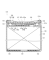
- the power storage device 10 includes a cylindrical case 20 with a bottom, a power storage element 30 disposed in the case 20 and including a pair of electrodes (not shown), and a pair of electrodes (not shown).
- a first lead 41 connected to one of the electrodes, a second lead 45 connected to the other electrode, and a sealing member 50 for sealing the open end 21a of the case 20 are provided.
- Power storage device 10 further includes first and second insulating plates 61 and 62 .
- the first and second insulating plates 61 and 62 are disk-shaped members each having a through hole.
- the case 20 has a cylindrical portion 21 having an open end 21a at one end (upper end in FIG. 1) and a bottom portion 22 closing the other end of the cylindrical portion 21 .
- An annular groove portion 21b protruding radially inward of the tubular portion 21 is formed in the vicinity of the open end portion 21a of the tubular portion 21 .
- the sealing member 50 is arranged on the inner peripheral surface of the groove portion 21b.
- the open end portion 21a of the case 20 is crimped to an outer peripheral portion 58 of a sealing plate 56, which will be described later, via a gasket 51, which will be described later. Thereby, the sealing member 50 is sandwiched between the groove portion 21b and the open end portion 21a, and the case 20 is sealed.
- the power storage element 30 has a generally cylindrical shape.
- the storage element 30 is configured by winding a positive electrode and a negative electrode (not shown) with a separator (not shown) interposed therebetween.
- the first lead 41 is connected to one electrode (positive electrode in this example) of the storage element 30 .
- the first lead 41 is composed of a strip-shaped metal sheet, but is not limited to this.
- a connection region 42 formed with two bent portions 43 is provided at the other end of the first lead 41 .
- This connection area 42 is connected to the projection 57 a of the sealing plate 56 .
- sealing plate 56 functions as a positive terminal of power storage device 10 .
- the first lead 41 is an example of a lead.
- the bent portion 43 is an example of displacement suppressing means.
- each bent portion 43 is formed at each end of the first lead 41 in the width direction (perpendicular to the plane of FIG. 1).
- Each bent portion 43 has a fold along the longitudinal direction of the first lead 41 (horizontal direction in FIG. 1).
- One bent portion 43 is arranged at one end of the first lead 41 in the width direction.
- the other bent portion 43 is arranged at the other widthwise end of the first lead 41 .
- Each bent portion 43 can be formed by making a cut in the first lead 41 and bending the first lead 41 along the longitudinal direction.
- the shape and dimensions of the two bent portions 43 may be the same or different.
- the two bent portions 43 of the present embodiment have symmetrical shapes with respect to a plane perpendicular to the main surface of the first lead 41 and passing through the center of the first lead 41, but two bent portions 43 having asymmetrical shapes with respect to the plane.
- a bent portion 43 may be provided.
- connection region 42 extends from the tip of the first lead 41 over a predetermined length.
- connection region 42 may extend over a predetermined length from a position some distance from the tip of the first lead 41 .
- the bent portion 43 is not formed at the tip of the first lead 41 .
- the second lead 45 is connected to the other electrode (negative electrode in this example) of the storage element 30 .
- the second lead 45 is composed of a strip-shaped metal sheet, but is not limited to this.
- the other end of the second lead 45 is connected to the bottom 22 of the case 20 .
- case 20 functions as a negative terminal of power storage device 10 .
- the projection 57a of the sealing plate 56 is inserted into the through hole 53a.
- a gap may or may not be formed between the projection 57a and the through hole 53a.
- the protrusion 57a is connected to the connection region 42 of the first lead 41 as described above. That is, the displacement portion 57 of the sealing plate 56 and the connection region 42 of the first lead 41 are connected via the through hole 53a.
- the protrusion 57a of the displacement portion 57 is displaced in the direction away from the storage element 30 (that is, in the direction away from the first lead 41).
- displacement of the first lead 41 is suppressed by the connection region 42 with high strength. Therefore, when the displacement of the protrusion 57a becomes large, the connection between the protrusion 57a and the first lead 41 is cut off. As a result, overcharging or the like is suppressed.
- connection region 42 of this embodiment is longer than the connection region 42 of the first embodiment. Specifically, one end and the other end of the connection region 42 respectively overlap the outer peripheral portion 58 of the sealing plate 56 when viewed from the axial direction of the case 20 (viewed from above in FIG. 3). In other words, one end and the other end of the connection region 42 are located outside the inner end of the outer peripheral portion 58 of the sealing plate 56 in the radial direction of the case 20 .
- the base portion 53 of the gasket 51 is sandwiched between one end portion of the connection region 42 and the outer peripheral portion 58 and between the other end portion of the connection region 42 and the outer peripheral portion 58 .
- the power storage device 110 of the present embodiment is a lithium ion secondary battery, but is not limited to this.
- the power storage device 110 may be a lithium ion capacitor, an electric double layer capacitor, an intermediate power storage device between a lithium ion secondary battery and a lithium ion capacitor, or other electrochemical devices.
- the power storage device 110 includes a cylindrical case 120 with a bottom, a power storage element 130 disposed in the case 120 and including a pair of electrodes (not shown), and a pair of electrodes (not shown).
- Power storage device 110 further includes first and second insulating plates 161 and 162 .
- the first and second insulating plates 161 and 162 are disk-shaped members each having a through hole.
- the case 120 has a cylindrical portion 121 having an open end 121a at one end (upper end in FIG. 5) and a bottom portion 122 closing the other end of the cylindrical portion 121.
- An annular groove portion 121b protruding radially inward of the cylindrical portion 121 is formed in the vicinity of the open end portion 121a of the cylindrical portion 121 .
- the sealing member 150 is arranged on the inner peripheral surface of the groove portion 121b.
- An open end portion 121a of the case 120 is crimped to an outer peripheral portion 158 of a sealing plate 156, which will be described later, via a gasket 151, which will be described later. Thereby, the sealing member 150 is sandwiched between the groove portion 121b and the open end portion 121a, and the case 120 is sealed.
- the power storage element 130 has a generally cylindrical shape.
- the storage element 130 is configured by winding a positive electrode and a negative electrode (not shown) with a separator (not shown) interposed therebetween.
- first lead 141 is connected to one electrode (positive electrode in this example) of the storage element 130 .
- the first lead 141 is made of strip-shaped metal foil, but is not limited to this.
- the other end of first lead 141 is connected to reinforcing member 170 .
- reinforcing member 170 is connected to sealing plate 156 , so sealing plate 156 functions as a positive electrode terminal of power storage device 110 .
- the first lead 141 is an example of a lead.
- Reinforcing member 170 is an example of displacement suppressing means.
- the second lead 142 is connected to the other electrode (negative electrode in this example) of the storage element 130 .
- the second lead 142 is made of strip-shaped metal foil, but is not limited to this.
- the other end of second lead 142 is connected to bottom 122 of case 120 .
- case 120 functions as a negative terminal of power storage device 110 .
- the sealing member 150 includes an insulating gasket 151 and a conductive sealing plate 156 .
- the gasket 151 has a compressed portion 152 interposed between the cylindrical portion 121 (groove portion 121 b ) and the sealing plate 156 and a base portion 153 overlapping the sealing plate 156 .
- Base 153 is arranged between sealing plate 156 and power storage element 130 .
- the base portion 153 has a planar shape having substantially the same size as the planar shape (circular shape) of the sealing plate 156 .
- An oval insertion hole 153 a is formed in the central region of the base portion 153 .
- the peripheral portion of the base portion 153 and the peripheral portion 158 of the sealing plate 156 are in close contact with each other.
- a reinforcing member 170 is arranged inside the base 153 .
- Base portion 153 covers the main surface of reinforcing member 170 on the opposite side (upper side in FIG. 5) from storage element 130, except for the region where insertion hole 153a is formed.
- the base portion 153 has a first opening 153c and a second opening 153d that cover the first portion 170a of the main surface of the reinforcing member 170 on the power storage element 130 side (lower side in FIG. 5) and expose the second portion 170b of the main surface.
- the first opening 153c is provided at a position (in this example, the central position of the base 153) corresponding to a first connecting portion 181, which will be described later.
- the second opening 153d is provided at a position corresponding to a second connection portion 182, which will be described later, and accommodates at least part of the other end of the first lead 141.
- First opening 153c and second opening 153d expose the main surface of reinforcing member 170 on the power storage element 130 side as second portion 170b at positions where they are arranged.
- Each of the first opening 153c and the second opening 153d is an example of at least one opening.
- the portion overlapping reinforcing member 170 protrudes toward storage element 130 more than the portion not overlapping reinforcing member 170 .
- the sealing plate 156 has a displacement portion 157 provided at its center, an outer peripheral portion 158 provided around the displacement portion 157 and sandwiched between the compression portions 152 of the gasket 151, and the displacement portion 157 and the outer peripheral portion 158. and a thin portion 159 .
- a protrusion 157 a protruding toward the storage element 130 is formed on the displacement portion 157 .
- the cross-sectional shape of the projection 157a (the cross-sectional shape in the cross section perpendicular to the axial direction of the case 120) is oval, but is not limited to this.
- the thickness of the thin portion 159 is smaller than the thickness of the displacement portion 157 and the thickness of the outer peripheral portion 158 .
- the reinforcing member 170 is provided inside the base 153 to reinforce the base 153 .
- the reinforcing member 170 is a conductive member and is made of metal, for example.
- the reinforcing member 170 of this embodiment is integrated with the gasket 151 by insert molding.
- a main surface (lower surface in FIG. 5) of reinforcing member 170 on the power storage element 130 side has a first portion 170a exposed from first opening 153c and second opening 153d, and a second portion 170b covered with base portion 153. .
- the reinforcing member 170 is connected to the first lead 141 by the second connecting portion 182 at the first portion 170a exposed from the second opening 153d.
- the projection 157a of the sealing plate 156 is inserted into the insertion hole 153a.
- a gap may or may not be formed between the projection 157a and the insertion hole 153a.
- the protrusion 157 a (displacement portion 157 ) of the sealing plate 156 is connected to the reinforcement member 170 at the first connection portion 181 .
- the displacement portion 157 of the sealing plate 156 is electrically connected to the first lead 141 via the conductive reinforcing member 170 .
- a first connecting portion 181 connecting the projection 157a and the reinforcing member 170 and a second connecting portion 182 connecting the reinforcing member 170 and the first lead 141 are arranged in the radial direction of the case 120. away from each other.
- the bonding strength of the first connecting portion 181 may be lower than the bonding strength of the second connecting portion 182 .
- the first connecting portion 181 and the second connecting portion 182 can be separately formed by laser welding, for example.
- the first connecting portion 181 may be formed by laser welding through the first opening 153c
- the second connecting portion 182 may be formed by laser welding through the second opening 153d.
- the base 153 of the gasket 151 is formed with a plurality of ventilation holes (through holes) 53b. Ventilation hole 153 b communicates with displacement portion 157 so that the internal pressure in case 120 is transmitted to displacement portion 157 .
- the projection 157a of the displacement portion 157 is displaced in a direction away from the power storage element 130 (that is, in a direction away from the reinforcing member 170 and the first lead 141).
- the displacement of the reinforcing member 170 and the first lead 141 is suppressed by the base portion 153 reinforced by the reinforcing member 170 . Therefore, when the displacement of the protrusion 157a becomes large, the connection between the protrusion 157a and the reinforcing member 170 is cut off. As a result, electrical connection between the displacement portion 157 and the first lead 141 is cut off, and overcharging and the like are suppressed.
- the power storage device 110 of this embodiment differs from that of the third embodiment in the shape of the reinforcing member 170 . Differences from the third embodiment will be mainly described below.
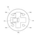
- the reinforcing member 170 of this modified example is formed in a cross-shaped plate shape. With this configuration, the base 153 of the gasket 151 can be reinforced more effectively.
- the power storage device 110 of this embodiment differs from that of the third embodiment in the shape of the reinforcing member 170 . Differences from the third embodiment will be mainly described below.
- the reinforcing member 170 of this embodiment is formed in a disc shape.
- a circular through-hole 170c is formed in the reinforcing member 170 at a position overlapping with the ventilation hole 153b.
- the shape of the through hole 170c is not limited to a circular shape. With this configuration, the base 153 of the gasket 151 can be reinforced more effectively.
- the present disclosure can be used for power storage devices.
Landscapes
- Engineering & Computer Science (AREA)
- Power Engineering (AREA)
- Chemical & Material Sciences (AREA)
- Chemical Kinetics & Catalysis (AREA)
- Electrochemistry (AREA)
- General Chemical & Material Sciences (AREA)
- Microelectronics & Electronic Packaging (AREA)
- Connection Of Batteries Or Terminals (AREA)
- Sealing Battery Cases Or Jackets (AREA)
- Electric Double-Layer Capacitors Or The Like (AREA)
Priority Applications (4)
| Application Number | Priority Date | Filing Date | Title |
|---|---|---|---|
| CN202280077986.5A CN118339713A (zh) | 2021-11-30 | 2022-11-25 | 蓄电装置 |
| JP2023564937A JPWO2023100768A1 (https=) | 2021-11-30 | 2022-11-25 | |
| EP22901201.8A EP4443637A4 (en) | 2021-11-30 | 2022-11-25 | Power storage device |
| US18/708,407 US20250030137A1 (en) | 2021-11-30 | 2022-11-25 | Power storage device |
Applications Claiming Priority (4)
| Application Number | Priority Date | Filing Date | Title |
|---|---|---|---|
| JP2021-194412 | 2021-11-30 | ||
| JP2021-194353 | 2021-11-30 | ||
| JP2021194353 | 2021-11-30 | ||
| JP2021194412 | 2021-11-30 |
Publications (1)
| Publication Number | Publication Date |
|---|---|
| WO2023100768A1 true WO2023100768A1 (ja) | 2023-06-08 |
Family
ID=86612133
Family Applications (1)
| Application Number | Title | Priority Date | Filing Date |
|---|---|---|---|
| PCT/JP2022/043547 Ceased WO2023100768A1 (ja) | 2021-11-30 | 2022-11-25 | 蓄電装置 |
Country Status (4)
| Country | Link |
|---|---|
| US (1) | US20250030137A1 (https=) |
| EP (1) | EP4443637A4 (https=) |
| JP (1) | JPWO2023100768A1 (https=) |
| WO (1) | WO2023100768A1 (https=) |
Cited By (2)
| Publication number | Priority date | Publication date | Assignee | Title |
|---|---|---|---|---|
| JPWO2024116623A1 (https=) * | 2022-12-01 | 2024-06-06 | ||
| WO2025249103A1 (ja) * | 2024-05-31 | 2025-12-04 | パナソニックIpマネジメント株式会社 | 蓄電装置 |
Families Citing this family (1)
| Publication number | Priority date | Publication date | Assignee | Title |
|---|---|---|---|---|
| EP4131592A4 (en) * | 2020-03-31 | 2024-07-31 | SANYO Electric Co., Ltd. | CYLINDRICAL BATTERY |
Citations (5)
| Publication number | Priority date | Publication date | Assignee | Title |
|---|---|---|---|---|
| JP2007287625A (ja) * | 2006-04-20 | 2007-11-01 | Fdk Corp | 密閉型電池およびその製造方法 |
| US20110104523A1 (en) * | 2009-06-15 | 2011-05-05 | Lg Chem, Ltd | Cap assembly of cylindrical rechargeable battery and cylindrical rechargeable battery |
| JP2012138343A (ja) * | 2010-12-10 | 2012-07-19 | Gs Yuasa Corp | 電池及び集電体 |
| JP2014524118A (ja) * | 2011-07-13 | 2014-09-18 | エルジー・ケム・リミテッド | 円筒型二次電池 |
| JP2021125304A (ja) | 2020-01-31 | 2021-08-30 | パナソニックIpマネジメント株式会社 | 蓄電装置 |
Family Cites Families (6)
| Publication number | Priority date | Publication date | Assignee | Title |
|---|---|---|---|---|
| JP2006147180A (ja) * | 2004-11-16 | 2006-06-08 | Toshiba Corp | 非水電解質二次電池 |
| KR100947071B1 (ko) * | 2007-11-23 | 2010-03-12 | 삼성에스디아이 주식회사 | 이차 전지 |
| KR102668193B1 (ko) * | 2016-01-04 | 2024-05-23 | 삼성에스디아이 주식회사 | 캡 조립체 및 이를 포함하는 이차 전지 |
| KR102082914B1 (ko) * | 2017-09-13 | 2020-02-28 | 주식회사 엘지화학 | 안전성이 향상된 이차전지 |
| JP7678526B2 (ja) * | 2020-03-31 | 2025-05-16 | パナソニックIpマネジメント株式会社 | 封口体および電池 |
| CN214336804U (zh) * | 2021-01-25 | 2021-10-01 | 宁德时代新能源科技股份有限公司 | 电池单体、电池以及用电装置 |
-
2022
- 2022-11-25 EP EP22901201.8A patent/EP4443637A4/en active Pending
- 2022-11-25 WO PCT/JP2022/043547 patent/WO2023100768A1/ja not_active Ceased
- 2022-11-25 US US18/708,407 patent/US20250030137A1/en active Pending
- 2022-11-25 JP JP2023564937A patent/JPWO2023100768A1/ja active Pending
Patent Citations (5)
| Publication number | Priority date | Publication date | Assignee | Title |
|---|---|---|---|---|
| JP2007287625A (ja) * | 2006-04-20 | 2007-11-01 | Fdk Corp | 密閉型電池およびその製造方法 |
| US20110104523A1 (en) * | 2009-06-15 | 2011-05-05 | Lg Chem, Ltd | Cap assembly of cylindrical rechargeable battery and cylindrical rechargeable battery |
| JP2012138343A (ja) * | 2010-12-10 | 2012-07-19 | Gs Yuasa Corp | 電池及び集電体 |
| JP2014524118A (ja) * | 2011-07-13 | 2014-09-18 | エルジー・ケム・リミテッド | 円筒型二次電池 |
| JP2021125304A (ja) | 2020-01-31 | 2021-08-30 | パナソニックIpマネジメント株式会社 | 蓄電装置 |
Non-Patent Citations (1)
| Title |
|---|
| See also references of EP4443637A4 |
Cited By (4)
| Publication number | Priority date | Publication date | Assignee | Title |
|---|---|---|---|---|
| JPWO2024116623A1 (https=) * | 2022-12-01 | 2024-06-06 | ||
| WO2024116623A1 (ja) * | 2022-12-01 | 2024-06-06 | 株式会社村田製作所 | 電池 |
| JP7800729B2 (ja) | 2022-12-01 | 2026-01-16 | 株式会社村田製作所 | 電池 |
| WO2025249103A1 (ja) * | 2024-05-31 | 2025-12-04 | パナソニックIpマネジメント株式会社 | 蓄電装置 |
Also Published As
| Publication number | Publication date |
|---|---|
| JPWO2023100768A1 (https=) | 2023-06-08 |
| US20250030137A1 (en) | 2025-01-23 |
| EP4443637A1 (en) | 2024-10-09 |
| EP4443637A4 (en) | 2025-07-30 |
Similar Documents
| Publication | Publication Date | Title |
|---|---|---|
| JP7576747B2 (ja) | 電池 | |
| WO2023100768A1 (ja) | 蓄電装置 | |
| JP7607214B2 (ja) | 蓄電装置 | |
| CN113169398B (zh) | 密封电池 | |
| JP6308071B2 (ja) | 角形二次電池およびその製造方法 | |
| KR20180057362A (ko) | 이차 전지 | |
| JP2016189246A (ja) | 角形二次電池 | |
| CN112368878A (zh) | 二次电池 | |
| WO2023127721A1 (ja) | 蓄電装置 | |
| CN117561645A (zh) | 圆筒形电池 | |
| JP6778641B2 (ja) | 角形二次電池 | |
| WO2023167010A1 (ja) | 円筒形電池 | |
| EP4411975A1 (en) | Electricity storage device and method for manufacturing electricity storage device | |
| JP7398719B2 (ja) | 密閉型電池 | |
| CN118339713A (zh) | 蓄电装置 | |
| CN118451601A (zh) | 集电板和蓄电装置 | |
| US20220271400A1 (en) | Battery | |
| JP7833662B2 (ja) | 蓄電装置および蓄電装置の製造方法 | |
| JP2012038545A (ja) | 円筒型蓄電池 | |
| WO2024203592A1 (ja) | 円筒形電池及び円筒形電池の製造方法 | |
| WO2024157743A1 (ja) | 二次電池 | |
| WO2024135555A1 (ja) | 円筒形電池 | |
| CN121548915A (zh) | 蓄电装置 | |
| CN120712690A (zh) | 圆筒形电池 | |
| JP2019145400A (ja) | 蓄電素子 |
Legal Events
| Date | Code | Title | Description |
|---|---|---|---|
| 121 | Ep: the epo has been informed by wipo that ep was designated in this application |
Ref document number: 22901201 Country of ref document: EP Kind code of ref document: A1 |
|
| WWE | Wipo information: entry into national phase |
Ref document number: 2023564937 Country of ref document: JP |
|
| WWE | Wipo information: entry into national phase |
Ref document number: 18708407 Country of ref document: US |
|
| WWE | Wipo information: entry into national phase |
Ref document number: 202280077986.5 Country of ref document: CN |
|
| NENP | Non-entry into the national phase |
Ref country code: DE |
|
| ENP | Entry into the national phase |
Ref document number: 2022901201 Country of ref document: EP Effective date: 20240701 |