WO2023100712A1 - 光照射装置、細胞培養装置、処理装置、光照射方法、および細胞培養方法 - Google Patents
光照射装置、細胞培養装置、処理装置、光照射方法、および細胞培養方法 Download PDFInfo
- Publication number
- WO2023100712A1 WO2023100712A1 PCT/JP2022/043103 JP2022043103W WO2023100712A1 WO 2023100712 A1 WO2023100712 A1 WO 2023100712A1 JP 2022043103 W JP2022043103 W JP 2022043103W WO 2023100712 A1 WO2023100712 A1 WO 2023100712A1
- Authority
- WO
- WIPO (PCT)
- Prior art keywords
- light
- liquid
- light irradiation
- irradiation device
- illumination light
- Prior art date
- Legal status (The legal status is an assumption and is not a legal conclusion. Google has not performed a legal analysis and makes no representation as to the accuracy of the status listed.)
- Ceased
Links
Images









Classifications
-
- A—HUMAN NECESSITIES
- A23—FOODS OR FOODSTUFFS; TREATMENT THEREOF, NOT COVERED BY OTHER CLASSES
- A23B—PRESERVATION OF FOODS, FOODSTUFFS OR NON-ALCOHOLIC BEVERAGES; CHEMICAL RIPENING OF FRUIT OR VEGETABLES
- A23B2/00—Preservation of foods or foodstuffs, in general
- A23B2/05—Preservation of foods or foodstuffs, in general by heating using irradiation or electric treatment
-
- A—HUMAN NECESSITIES
- A23—FOODS OR FOODSTUFFS; TREATMENT THEREOF, NOT COVERED BY OTHER CLASSES
- A23B—PRESERVATION OF FOODS, FOODSTUFFS OR NON-ALCOHOLIC BEVERAGES; CHEMICAL RIPENING OF FRUIT OR VEGETABLES
- A23B70/00—Preservation of non-alcoholic beverages
- A23B70/50—Preservation of non-alcoholic beverages by irradiation or electric treatment, without heating
-
- A—HUMAN NECESSITIES
- A61—MEDICAL OR VETERINARY SCIENCE; HYGIENE
- A61K—PREPARATIONS FOR MEDICAL, DENTAL OR TOILETRY PURPOSES
- A61K35/00—Medicinal preparations containing materials or reaction products thereof with undetermined constitution
- A61K35/12—Materials from mammals; Compositions comprising non-specified tissues or cells; Compositions comprising non-embryonic stem cells; Genetically modified cells
-
- A—HUMAN NECESSITIES
- A61—MEDICAL OR VETERINARY SCIENCE; HYGIENE
- A61K—PREPARATIONS FOR MEDICAL, DENTAL OR TOILETRY PURPOSES
- A61K41/00—Medicinal preparations obtained by treating materials with wave energy or particle radiation ; Therapies using these preparations
- A61K41/10—Inactivation or decontamination of a medicinal preparation prior to administration to an animal or a person
- A61K41/17—Inactivation or decontamination of a medicinal preparation prior to administration to an animal or a person by ultraviolet [UV] or infrared [IR] light, X-rays or gamma rays
-
- C—CHEMISTRY; METALLURGY
- C12—BIOCHEMISTRY; BEER; SPIRITS; WINE; VINEGAR; MICROBIOLOGY; ENZYMOLOGY; MUTATION OR GENETIC ENGINEERING
- C12M—APPARATUS FOR ENZYMOLOGY OR MICROBIOLOGY; APPARATUS FOR CULTURING MICROORGANISMS FOR PRODUCING BIOMASS, FOR GROWING CELLS OR FOR OBTAINING FERMENTATION OR METABOLIC PRODUCTS, i.e. BIOREACTORS OR FERMENTERS
- C12M1/00—Apparatus for enzymology or microbiology
-
- C—CHEMISTRY; METALLURGY
- C12—BIOCHEMISTRY; BEER; SPIRITS; WINE; VINEGAR; MICROBIOLOGY; ENZYMOLOGY; MUTATION OR GENETIC ENGINEERING
- C12M—APPARATUS FOR ENZYMOLOGY OR MICROBIOLOGY; APPARATUS FOR CULTURING MICROORGANISMS FOR PRODUCING BIOMASS, FOR GROWING CELLS OR FOR OBTAINING FERMENTATION OR METABOLIC PRODUCTS, i.e. BIOREACTORS OR FERMENTERS
- C12M1/00—Apparatus for enzymology or microbiology
- C12M1/12—Apparatus for enzymology or microbiology with sterilisation, filtration or dialysis means
-
- C—CHEMISTRY; METALLURGY
- C12—BIOCHEMISTRY; BEER; SPIRITS; WINE; VINEGAR; MICROBIOLOGY; ENZYMOLOGY; MUTATION OR GENETIC ENGINEERING
- C12M—APPARATUS FOR ENZYMOLOGY OR MICROBIOLOGY; APPARATUS FOR CULTURING MICROORGANISMS FOR PRODUCING BIOMASS, FOR GROWING CELLS OR FOR OBTAINING FERMENTATION OR METABOLIC PRODUCTS, i.e. BIOREACTORS OR FERMENTERS
- C12M1/00—Apparatus for enzymology or microbiology
- C12M1/42—Apparatus for the treatment of microorganisms or enzymes with electrical or wave energy, e.g. magnetism, sonic waves
-
- C—CHEMISTRY; METALLURGY
- C12—BIOCHEMISTRY; BEER; SPIRITS; WINE; VINEGAR; MICROBIOLOGY; ENZYMOLOGY; MUTATION OR GENETIC ENGINEERING
- C12M—APPARATUS FOR ENZYMOLOGY OR MICROBIOLOGY; APPARATUS FOR CULTURING MICROORGANISMS FOR PRODUCING BIOMASS, FOR GROWING CELLS OR FOR OBTAINING FERMENTATION OR METABOLIC PRODUCTS, i.e. BIOREACTORS OR FERMENTERS
- C12M3/00—Tissue, human, animal or plant cell, or virus culture apparatus
-
- C—CHEMISTRY; METALLURGY
- C12—BIOCHEMISTRY; BEER; SPIRITS; WINE; VINEGAR; MICROBIOLOGY; ENZYMOLOGY; MUTATION OR GENETIC ENGINEERING
- C12N—MICROORGANISMS OR ENZYMES; COMPOSITIONS THEREOF; PROPAGATING, PRESERVING, OR MAINTAINING MICROORGANISMS; MUTATION OR GENETIC ENGINEERING; CULTURE MEDIA
- C12N1/00—Microorganisms; Compositions thereof; Processes of propagating, maintaining or preserving microorganisms or compositions thereof; Processes of preparing or isolating a composition containing a microorganism; Culture media therefor
-
- C—CHEMISTRY; METALLURGY
- C12—BIOCHEMISTRY; BEER; SPIRITS; WINE; VINEGAR; MICROBIOLOGY; ENZYMOLOGY; MUTATION OR GENETIC ENGINEERING
- C12N—MICROORGANISMS OR ENZYMES; COMPOSITIONS THEREOF; PROPAGATING, PRESERVING, OR MAINTAINING MICROORGANISMS; MUTATION OR GENETIC ENGINEERING; CULTURE MEDIA
- C12N13/00—Treatment of microorganisms or enzymes with electrical or wave energy, e.g. magnetism, sonic waves
Definitions
- the present disclosure relates to a light irradiation device and the like for performing sterilization.
- Patent Document 1 describes that light specified by a spectrum having a peak wavelength in a wavelength range of 400 nm or more and 410 nm or less can exhibit a high sterilizing effect.
- a light irradiation device includes an illumination unit capable of irradiating an irradiation target with illumination light having an irradiance of 5 mW/cm 2 or more in a wavelength range of 380 nm or more and 420 nm or less.
- a light irradiation method includes an irradiation step of irradiating an irradiation target with illumination light having an irradiance of 5 mW/cm 2 or more in a wavelength range of 380 nm or more and 420 nm or less; and a control step of controlling the irradiance of the illumination light when the object is irradiated with the illumination light and/or the time during which the object is irradiated with the illumination light.
- FIG. 10 is a diagram showing a schematic configuration of a processing apparatus according to Embodiment 3 of the present disclosure. It is an enlarged view which shows the structure of the filter with which the said processing apparatus is provided.
- FIG. 11 is a diagram showing a schematic configuration of a processing apparatus according to Embodiment 4 of the present disclosure; It is a flow chart which shows an example of processing of liquid using the above-mentioned treating device.
- FIG. 11 is a diagram showing a schematic configuration of a processing device 1B according to Embodiment 5 of the present disclosure; It is a sectional view showing composition of a column with which the above-mentioned processing equipment is provided.
- FIG. 4 is a graph showing measurement results of a first test as an experimental example of the present disclosure
- 7 is a graph showing measurement results of a second test as an experimental example of the present disclosure
- 7 is a graph showing measurement results of a third test as an experimental example of the present disclosure
- FIG. 11 is a graph showing measurement results of a fourth test as an experimental example of the present disclosure
- FIG. 1 is a front view showing an example of the configuration of a cell culture device 1 according to this embodiment.
- the cell culture device 1 includes a housing 10 , a controller 20 and a light irradiation device 30 .
- the housing 10 may accommodate a culture container 50 containing cultured cells and a medium for culturing the cultured cells.
- a plurality of support portions 11 may be arranged in the vertical direction inside the housing 10 .
- the culture vessel 50 may be made of a material that is translucent to visible light.
- the culture container 50 can be placed on the support portion 11.
- the cell culture apparatus 1 shown in FIG. 1 includes three support sections 11, the number of support sections 11 is not particularly limited. As will be described later, the supporting portion 11 may be translucent to visible light.
- the control unit 20 controls various functions of the cell culture device 1 .
- the control unit 20 may control the temperature, humidity, O 2 concentration, and/or CO 2 concentration inside the housing 10 using, for example, known methods.
- the light irradiation device 30 may be provided inside the housing 10 so as to be able to irradiate the culture container 50 with illumination light.
- the light irradiation device 30 may include a light emitting element 31 (illumination section) and an ultraviolet light reduction section 32, as shown in FIG. FIG. 1 shows a case where the light irradiation device 30 is provided on the top surface inside the housing 10 .
- the support portion 11 of the housing 10 is translucent, and the illumination light emitted from the light irradiation device 30 can reach all the culture vessels 50 placed on each support portion 11. be.
- the support portion 11 having translucency the number of light irradiation devices 30 mounted on the cell culture device 1 can be reduced. Therefore, the manufacturing cost of the cell culture device 1 can be reduced.
- the light-emitting element 31 can irradiate an irradiation target with illumination light having an irradiance of 5 mW/cm 2 or more in a wavelength range of 380 nm or more and 420 nm or less.
- the inventors of the present invention have found through intensive research that a high antibacterial action can be obtained by irradiating an object to be irradiated with illumination light having the above irradiance. Since a higher antibacterial effect can be obtained, the irradiance to the irradiated object may be 10 mW/cm 2 or more, or may be 20 mW/cm 2 or more.
- the illumination light emitted from the light emitting element 31 does not contain ultraviolet light, or contains ultraviolet light that does not damage the irradiation target.
- the integrated illuminance of the illumination light irradiated to the irradiation target by the light irradiation device 30 may be 1.2 ⁇ 10 5 mJ/cm 2 or more, and may be 2 ⁇ 10 5 mJ/cm 2 . or more.
- the integrated illuminance is obtained from the irradiance of the illumination light when the illumination light is applied to the culture vessel to be irradiated, and the time during which the culture vessel is illuminated with the illumination light.
- the control unit 20 can control the irradiance and the irradiation time of the illumination light.
- the ultraviolet light reducing unit 32 reduces the amount of light in the wavelength band of the ultraviolet region contained in the illumination light emitted from the light emitting element 31 .
- the ultraviolet light reducing section 32 may be, for example, an ultraviolet filter.
- the illumination light from which the amount of light in the wavelength band in the ultraviolet region has been reduced by the ultraviolet light reducing unit 32 has an irradiance of 0.2 mW/cm 2 or less on the irradiation target in a wavelength region of less than 380 nm. There may be. Thereby, it is possible to suppress the decrease in the viability of the cultured cells.
- FIG. 2 is a flow chart showing an example of the processing of the cell culture method according to this embodiment.
- a cell culture medium is prepared (preparation step, step S1).
- the absorbance at 405 nm of the cell culture medium in this embodiment may be 0.33 or less.
- the cell culture device 1 may be used as a device for culturing animal cells that do not contain chlorophyll.
- step S2 the culture container 50 containing the cell culture medium seeded with the cultured cells is placed on the support portion 11 of the housing 10 (step S2).
- the cultured cells are cultured while irradiating the culture vessel with illumination light having an irradiance of 5 mW/cm 2 or more to the irradiation target in the wavelength region of 380 nm or more and 420 nm or less by the light irradiation device 30 (irradiation step, Culture step, step S3).
- the cells can be cultured while killing only bacteria that are not desired to proliferate without damaging the cultured cells to be cultured.
- step S2 the controller 20 controls the irradiance of the illumination light applied to the culture vessel and/or the duration of illumination light irradiation to the culture vessel (control step). Specifically, the control unit 20 controls the integrated illuminance of the illumination light irradiated to the irradiation target by the light irradiation device 30 to be 1.2 ⁇ 10 5 mJ/cm 2 or more.
- the irradiation step and the control step are a light irradiation method according to one aspect of the present disclosure.
- the mode of using the light irradiation device 30 in the cell culture device 1 for culturing cells has been described, but the light irradiation device 30 can also be used for other purposes.
- the light irradiation device 30 can be used as a sterilization device.
- the light irradiation device 30 can be used for blood contained in a transparent container such as blood for transfusion (however, blood from which red blood cells have been removed).
- a transparent container for containing blood for transfusion is usually made of polystyrene, which does not transmit ultraviolet rays, and therefore cannot be sterilized by ultraviolet irradiation.
- the light irradiation device 30 of the present disclosure irradiates visible light in a wavelength range of 380 nm or more and 420 nm or less, so that the light can reach the inside of the transparent container. Therefore, the inside of the transparent container can be sterilized without damaging the cells of the blood components. For the same reason, the light irradiation device 30 may also be used for joint parts used in dialysis.
- the light irradiation device 30 may be used for food and/or beverages. Food and beverages cannot undergo sterilization processes such as gamma sterilization. Therefore, the expiration date is shortened. Also, irradiation of foods and beverages with ultraviolet light destroys their nutritional components. On the other hand, the light irradiation device 30 of the present disclosure irradiates visible light in the wavelength range of 380 nm or more and 420 nm or less, so that sterilization can be performed without destroying the nutritional components of foods and beverages, and consumption Deadlines can be extended.
- FIG. 3 is a front view showing the configuration of the cell culture device 1A according to this embodiment.
- the light irradiation device 30 is provided on the top surface inside the housing 10 .
- an irradiation device 30 is provided in the cell culture apparatus 1A according to the present embodiment.
- the light irradiation device 30 is provided for each stage divided by the support portion 11 of the housing 10, variations in the intensity of the light irradiated to the culture vessel can be reduced. can be done.
- the supporting portion 11 does not have to be translucent.
- Cell preparations are produced by culturing cells taken from donors. Specifically, cell preparations are prepared by first culturing cells collected from a donor to create a master cell bank, expanding the cells in the master cell bank to create a working cell bank, and further expanding and culturing the cells in the working cell bank. It is a liquid containing mass-produced cells. Mass-produced cell preparations are dispensed into small containers. If a cell preparation dispensed into a small container is contaminated with contaminants (eg, bacteria, endotoxin, etc.), it can cause serious infections or fever in the human body. A technique for removing a substance to be removed contained in a liquid is disclosed in Patent Document 2, for example.
- a processing apparatus and a processing method for dispensing a liquid containing cultured cells into small containers will be described.
- the processing apparatus of the present disclosure does not necessarily process liquid containing cultured cells, and can process liquid containing cells collected from a specimen, for example.
- FIG. 4 is a diagram showing a schematic configuration of the processing device 101 in this embodiment.
- the processing apparatus 101 includes a storage container 110, a light irradiation unit 120 (light irradiation device), a filter 130 (removal unit), a pump 140 (liquid delivery unit), and a dispensing unit 150. , tube 160 .
- the processing device 101 is a dispensing device for dispensing the cell preparation as the liquid L containing cells stored in the storage container 110 into the small container 200 .
- the storage container 110 is a container that stores the liquid L containing cultured cells.
- the storage container 110 stores the liquid L mass-produced by the expansion culture from the working cell bank.
- Liquid L may be a suspension of cultured cells in saline.
- the cell density of liquid L may be 1 ⁇ 10 5 cells/kg or more, or 1 ⁇ 10 6 cells/kg or more.
- the storage container 110 is made of a translucent material.
- the light irradiation unit 120 irradiates the liquid L stored in the storage container 110 with irradiation light (illumination light) having a peak wavelength of 380 nm or more and 420 nm or less.
- the light irradiation unit 120 may be configured by, for example, an LED (light emitting diode).
- the light irradiation unit 120 is capable of irradiating an irradiation target with irradiation light having an irradiance of 5 mW/cm 2 or more in a wavelength range of 380 nm or more and 420 nm or less.
- the inventors of the present invention have found through intensive research that a high antibacterial effect can be obtained by irradiating an object to be irradiated with irradiation light having the above irradiance.
- the liquid L may contain anaerobic bacteria (eg, Staphylococcus aureus, Bacillus subtilis, Pseudomonas aeruginosa, etc.), aerobic bacteria (eg, Sporigenus sporigenus). fungi, etc.), fungi (eg, yeast fungi, Aspergillus niger, etc.), and bacteria such as mycoplasma.
- anaerobic bacteria eg, Staphylococcus aureus, Bacillus subtilis, Pseudomonas aeruginosa, etc.
- aerobic bacteria eg, Sporigenus sporigenus
- fungi, etc. fungi
- fungi eg, yeast fungi, Aspergillus niger, etc.
- bacteria such as mycoplasma.
- the irradiance to the object to be irradiated may be 10 mW/cm 2 or more in order to enhance the antibacterial effect. By setting the irradiance to the object to be irradiated to 20 mW/cm 2 or more, the antibacterial action can be further enhanced.
- the irradiation light emitted from the light irradiation unit 120 does not contain ultraviolet light, or contains ultraviolet light to the extent that it does not damage the irradiation target.
- the irradiance is less than 5 mW/cm 2 , the effect of inactivating bacteria is reduced. If the irradiance is higher than 100 mW/cm 2 , the irradiance may be set to 100 mW/cm 2 or less because the effect on the cells is increased.
- the light irradiation unit 120 can inactivate bacteria without affecting cells by irradiating irradiation light having the above configuration.
- the integrated illuminance of the irradiation light irradiated to the irradiation target by the light irradiation unit 120 may be 1.2 ⁇ 10 5 mJ/cm 2 or more, and may be 2 ⁇ 10 5 mJ/cm 2 . or more.
- the integrated illuminance may be 4.0 ⁇ 10 5 mJ/cm 2 or less for the purpose of reducing heat generation and damage to cells.
- the integrated illuminance is obtained from the irradiance of the irradiation light when the liquid L to be irradiated is irradiated with the irradiation light, and the time during which the liquid L is irradiated with the irradiation light.
- the absorbance at 405 nm for irradiation is 0.33 or less. Therefore, the absorbance at 405 nm of the liquid L in this embodiment may be 0.33 or less.
- the irradiation light emitted from the light irradiation unit 120 may further include light with a wavelength longer than 420 nm.
- bacteria can be further inactivated by the influence of molecular vibration caused by the light.
- the wavelength is longer than 10,000 nm, the effect of inactivating bacteria is reduced because bacteria are less susceptible to molecular vibrations caused by infrared light, so it is not necessary to include light with a wavelength longer than 10,000 nm. .
- the filter 130 is provided downstream of the light irradiation section 120 in the path along which the liquid L moves from the storage container 110 to the small container 200 in the processing apparatus 101 .
- the filter 130 is connected to the storage container 110 by a tube 160 made of resin, for example.
- the filter 130 removes the removal target substance contained in the liquid L after being irradiated with the irradiation light by the light irradiation unit 120 .
- endotoxin contained in the liquid L containing cultured cells and/or bacteria inactivated by the light irradiation unit 120 are treated as substances to be removed.
- Endotoxin is a substance containing lipopolysaccharide as a constituent.
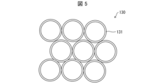
- FIG. 5 is an enlarged view showing the configuration of the filter 130.
- the filter 130 is constructed by bundling a plurality of hollow fibers 131 .
- FIG. 6 is an enlarged view of the hollow fiber 131 viewed from a direction perpendicular to the longitudinal direction. As shown in FIG. 6, the hollow fiber 131 has a plurality of holes 132 formed in the membrane constituting the hollow fiber 131 and having a size that allows endotoxin to pass through but does not allow cells to pass through.
- the hollow fibers 131 may be made of, for example, cellulose, polysulfone, polyethersulfone, polyester-based polymer alloy, ethylene vinyl alcohol copolymer, polymethyl methacrylate, polyacrylonitrile, polyvinyl alcohol, polyolefin, and/or polyamide. good.
- endotoxin is generated from bacteria (for example, Pseudomonas aeruginosa) that have been inactivated and killed by the light irradiation unit 120, when the liquid L inactivated by the light irradiation unit 120 is directly dispensed into the small container 200,
- the liquid L contained in the small container 200 may contain endotoxin.
- the endotoxin contained in the liquid L can be removed by passing the liquid L through the filter 130 before dispensing the liquid L into the small container 200 .
- the filter 130 may have a longitudinal length of 50 to 1000 mm.
- the filter 130 may have a hollow inner diameter of 50-4000 ⁇ m and a diameter of 200-5000 ⁇ m.
- the filter 130 may have a thickness of 150 to 1000 ⁇ m.
- the filter 130 may be composed of an organic material, an inorganic material, or a composite material of an organic material and an inorganic material. If the filter 130 comprises organic materials, it may be a mixture of different organics, such as polymer alloys. Filter 130 may be surface treated with an organic or inorganic material.
- the pump 140 can send the liquid L from the storage container 110 to the filter 130 through the tube 160 .
- the pump 140 may be, for example, a magnetically levitated pump in which the impeller floats contactlessly within a sealed casing and is driven by the rotating magnetic field of the motor.
- the dispensing unit 150 aseptically dispenses the liquid L from which endotoxin has been removed by the filter 130 into a plurality of small containers 200 .
- "aseptically” means that the instrument, device, and/or site to be used is kept sterile.
- the configuration of the pipetting unit 150 is not particularly limited as long as the liquid L can be pipetted aseptically, and conventionally known devices can be used.
- the dispensing unit 150 may dispense 0.5 ml to 20 ml or 1 ml to 15 ml of the liquid L into the small container 200 .
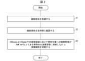
- FIG. 7 is a flow chart showing an example of processing of the liquid L using the processing device 101. As shown in FIG.
- the liquid L containing cultured cells stored in the storage container 110 is exposed to light in the wavelength region of 380 nm or more and 420 nm or less using the light irradiation unit 120. is irradiated with irradiation light having a peak wavelength (step S101, light irradiation step). This inactivates bacteria contained in the liquid L while reducing damage to cells.
- the liquid L is sent from the storage container 110 to the filter 130 by driving the pump 140 (step S102).
- step S103 removal step.
- the endotoxin generated from the bacteria inactivated by the light irradiation in step S101 can be removed from the liquid L through the holes 132 formed in the hollow fibers 131 .
- step S104 the liquid L from which endotoxin has been removed in step S103 is dispensed into a plurality of small containers 200 using the dispensing unit 150 (step S104).
- step S101 bacteria contained in the liquid L can be inactivated while reducing damage to cells. Furthermore, endotoxin generated from the inactivated bacteria can be removed from the liquid L in step S103. As a result, liquid L free of bacteria and endotoxin can be dispensed.
- a cell-containing product can be produced through the above treatment method. That is, the present disclosure also discloses methods for producing cell inclusions, including the processing methods described above.
- FIG. 8 is a diagram showing a schematic configuration of the processing device 101A in this embodiment. As shown in FIG. 8, the processing apparatus 101A differs from the processing apparatus 101 of the third embodiment in the location where the light irradiation unit 120 is arranged.
- the light irradiation unit 120 in this embodiment is arranged near the tube 160 connecting the storage container 110 and the filter 130, and can irradiate the tube 160 with irradiation light.
- the tube 160 in this embodiment has translucency.
- the light irradiation unit 120 irradiates the tube 160 with irradiation light, so that the liquid L in the tube 160 can be irradiated with the irradiation light.
- FIG. 9 is a flowchart showing an example of liquid L processing using the processing apparatus 101A.
- the liquid L is sent from the storage container 110 to the filter 130 by driving the pump 140 (step S111).
- the light irradiation unit 120 irradiates the tube 160 with irradiation light.
- the liquid L in the tube 160 is irradiated with irradiation light (step S112, light irradiation step). This inactivates bacteria contained in the liquid L while reducing damage to cells.
- step S113 removal step
- endotoxin generated from the bacteria inactivated by the light irradiation in step S112 can be removed from the liquid L through the holes 132 formed in the hollow fibers 131 .
- step S113 the liquid L from which endotoxin has been removed in step S113 is dispensed into a plurality of small containers 200 using the dispensing unit 150 (step S114).
- step S112 only bacteria contained in the liquid L can be inactivated while reducing damage to cells. Furthermore, endotoxin generated from the inactivated bacteria can be removed from the liquid L in step S113. As a result, liquid L free of bacteria and endotoxin can be dispensed. As described above, according to the liquid L processing method of the present embodiment, it is possible to dispense the liquid L from which bacteria and endotoxin have been removed while reducing damage to cells.
- FIG. 8 illustrates an example in which the light irradiation unit 120 irradiates the tube 160 connecting the storage container 110 and the pump 140 with irradiation light
- the processing apparatus of the present disclosure is not limited to this.
- the tube 160 connecting the filter 130 and the pump 140 may be irradiated with irradiation light.
- the irradiation light may be applied to the tube 160 connecting the 140 .
- FIG. 10 is a diagram showing a schematic configuration of the processing device 101B in this embodiment. As shown in FIG. 10, the processing apparatus 101B includes a column 170 (removal section) instead of the filter 130 in the third embodiment.
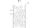
- FIG. 11 is a cross-sectional view showing the configuration of the column 170.
- FIG. FIG. 11 is a schematic diagram for facilitating understanding, and it should be noted that the actual size of each part differs from the size shown in FIG.
- the column 170 has a filling section 172 filled with an adsorbent 171 therein.
- the adsorbent 171 is an adsorbent capable of adsorbing endotoxin.
- the adsorbent 171 may be composed of, for example, an organic material or a composite material of organic and inorganic materials.
- the adsorbent 171 may be fibrous, spherical, sheet-like, or crushed, for example. If the adsorbent 171 comprises an organic material, it may be a mixture of different organics, such as a polymer alloy.
- the adsorbent 171 may be surface-treated with an organic or inorganic substance.
- the filling part 172 is filled with the adsorbent 171 so that the cells can pass through and the endotoxin is difficult to pass through.
- FIG. 12 is a flow chart showing an example of processing of the liquid L using the processing device 101B.
- the liquid L containing cultured cells stored in the storage container 110 is irradiated with the light irradiation unit 120 at a peak wavelength of 380 nm or more and 420 nm or less.
- step S121 light irradiation step. This inactivates only bacteria contained in the liquid L while reducing damage to cells.
- the liquid L is sent from the storage container 110 to the filter 130 by driving the pump 140 (step S122).
- step S123 removal step
- the endotoxin is adsorbed on the adsorbent 171, and the endotoxin generated from the bacteria inactivated by the light irradiation in step S121 can be removed from the liquid L.
- step S123 the liquid L from which endotoxin has been removed in step S123 is dispensed into a plurality of small containers 200 using the dispensing unit 150 (step S124).
- step S121 only bacteria contained in the liquid L can be inactivated while reducing damage to cells. Furthermore, endotoxins generated by the inactivated bacteria can be removed from the liquid L in step S123. As a result, liquid L free of bacteria and endotoxin can be dispensed. As described above, according to the method for treating the liquid L described above, it is possible to dispense the liquid L from which bacteria and endotoxin have been removed while reducing damage to cells.
- a processing apparatus may be configured to include both the filter 130 described in Embodiment 3 and the column 170 described in Embodiment 5 as a removal unit that removes endotoxin. Thereby, the possibility that the liquid L to be dispensed is mixed with endotoxin can be reduced.
- a light source that emits white light including wavelengths in the visible light region (hereinafter referred to as the first light source), or light having a sharp intensity peak at a wavelength of 405 nm (in the present disclosure, a single wavelength of 405 nm) NB (Nutrient Broth), which is considered to have a photosensitizing component, is irradiated with light emitted from an LED light source (hereinafter referred to as a second light source) that emits light),
- the amounts of active oxygen generated by light from both light sources were compared and measured. The measurement was performed multiple times by changing the dilution ratio of the NB medium.
- NB medium a stock solution was prepared by dissolving a commercially available powdered reagent for NB medium in pure water so that the concentration of the NB powder was 8 mg/mL. Using the dilution rate of this stock solution as 1, NB media with various dilution rates were prepared and used for experiments.
- the irradiance was 1.3 mW/cm 2 for the first light source and 31.1 mW/cm 2 for the second light source at 395 to 415 nm, and irradiation was performed for 120 minutes.
- a 96-well plate was used as the culture vessel, and after irradiating 0.1 mL of the medium, the amount of active oxygen generated was measured.
- an apparatus SpectraMax M2 manufactured by Molecular Devices was used, and the measured value obtained was converted to H 2 O 2 concentration.
- ⁇ Second test> The light emitted from the first light source or the light emitted from the second light source is applied to Staphylococcus aureus seeded in the same culture container as the first test containing the NB medium, and the antibacterial activity value Measured measurements. Light irradiation was performed 24 hours after inoculation of Staphylococcus aureus in the culture container, and the irradiation time was 2 hours. Cultivation and measurement were performed multiple times by changing the dilution ratio of the NB medium. In a second test, Staphylococcus aureus was also seeded in a culture vessel containing water containing no NB medium. The measurement of the antibacterial activity value in the second test was performed according to JIS 1702 and JISR1756.
- ⁇ Third test> The absorbance of light with a wavelength of 405 nm was measured while changing the dilution ratio of the NB medium.
- the same culture vessel as in the first test and the apparatus SpectraMax M2 manufactured by Molecular Devices were used.
- FIG. 13 is a graph showing the measurement results of the first test. As shown in FIG. 13, the amount of active oxygen generated increased as the concentration of the NB medium increased, regardless of whether the first light source or the second light source was used.
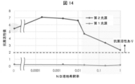
- FIG. 14 is a graph showing the measurement results of the second test. As shown in FIG. 14, the antibacterial activity value was low when the first light source was used. In contrast, when the second light source was used, the antibacterial activity value was high. In the second test, when the second light source was used, the antibacterial activity value decreased when the dilution ratio of the NB medium was 0.02 or more.
- FIG. 15 is a graph showing the measurement results of the third test. As shown in FIG. 15, in the second test, the absorbance at a wavelength of 405 nm was high when the NB medium with a dilution rate of 0.02 or more was used, which reduced the antibacterial activity value.
- the antibacterial activity decreased in the high-concentration NB medium in the second test because the NB medium absorbed light with a wavelength of 405 nm, and the amount of light reaching the cells of Staphylococcus aureus This is thought to be due to a decrease in the intracellular photosensitizing effect of Staphylococcus aureus.
- the antibacterial activity value was also high when water containing no NB medium was used.
- the antibacterial activity value is 2 or more, it is considered to have antibacterial activity, so when the second light source was used in the second test, there was an antibacterial effect in all tests. That is, in other words, it was shown that an antibacterial effect can be obtained by irradiating light on an irradiation target having an absorbance of 0.33 or less for light with a wavelength of 405 nm. From the graph shown in FIG. 15, it is considered that the antibacterial activity value becomes less than 2 when the dilution ratio of the NB medium is greater than 1, that is, when the absorbance is greater than 0.331.
- Ultraviolet light, single-wavelength light with a wavelength of 405 nm, or single-wavelength light with a wavelength of 472 nm is applied to human retinal pigment epithelial cells in a dedicated medium containing commercially available 2% FBS (Fetal Bovine Serum). The viability of human retinal pigment epithelial cells was measured. The integrated illuminance in each test was 2.2 ⁇ 10 5 mJ/cm 2 . Culture and light irradiation were performed for 2 hours, and the number of living cells before and after culture was counted using a commercially available Cell Counting Kit-8 to calculate the survival rate.
- FIG. 16 is a graph showing the measurement results of the fourth test. As shown in FIG. 16, when irradiated with ultraviolet rays, the survival rate of human retinal pigment epithelial cells was almost 0%, whereas light with a single wavelength of 405 nm or single wavelength with a wavelength of 472 nm was used. When exposed to light, the viability of human retinal pigment epithelial cells was approximately 80%.
- a light irradiation device includes an illumination unit capable of irradiating an irradiation target with illumination light having an irradiance of 5 mW/cm 2 or more in a wavelength range of 380 nm or more and 420 nm or less.
- the irradiance may be 10 mW/cm 2 or more.
- the irradiance may be 20 mW/cm 2 or more.
- a light irradiation device is the light irradiation device according to any one of Aspects 1 to 3 above, wherein the integrated illuminance of the illumination light with which the object is irradiated is 1.2 ⁇ 10 5 mJ/cm 2 or more.
- a light irradiation device in any one of Aspects 1 to 3, wherein the integrated illuminance of the illumination light irradiated to the irradiation target is 2 ⁇ 10 5 mJ/cm 2 or more. good.
- the illumination light has an irradiance of 0.2 mW/cm 2 or less on the irradiation target in a wavelength region of less than 380 nm.
- a light irradiation device in any one of Aspects 1 to 6 above, further includes an ultraviolet light reducing unit that reduces the amount of light in a wavelength band of an ultraviolet region included in the illumination light irradiated to the irradiation target. may be
- the absorbance at a wavelength of 405 nm of the irradiation target may be 0.33 or less.
- a light irradiation device is a light irradiation device according to any one of aspects 1 to 8, wherein the irradiation target is a culture container containing cultured cells and a culture medium for culturing the cultured cells. good.
- the irradiation target may be blood from which red blood cells have been removed.
- the irradiation target may be food and/or beverage.
- a cell culture device is a case capable of accommodating the light irradiation device according to any one of aspects 1 to 8, cultured cells, and a culture container containing a culture medium for culturing the cultured cells. and a controller that controls the temperature, humidity, O 2 concentration, and/or CO 2 concentration in the housing, and the light irradiation device can irradiate the culture container with illumination light.
- a light irradiation method includes an irradiation step of irradiating an irradiation target with illumination light having an irradiance of 5 mW/cm 2 or more in a wavelength range of 380 nm or more and 420 nm or less; and a control step of controlling the irradiance of the illumination light when the object is irradiated with the illumination light and/or the time during which the object is irradiated with the illumination light.
- a cell culture method includes a preparation step of preparing a cell medium having an absorbance of 0.33 or less, and an irradiance of 5 mW/cm 2 or more to the cell medium in a wavelength range of 380 nm or more and 420 nm or less. and a culturing step of culturing the cells while irradiating with illumination light.
- the illumination light may have an irradiance of 0.2 mW/cm 2 or less on the cell culture medium in a wavelength region of less than 380 nm. .
- a processing method includes a light irradiation step of irradiating a liquid containing cells with irradiation light having a peak wavelength of 380 nm or more and 420 nm or less, and after the light irradiation step, an object to be removed contained in the liquid and a removal step of removing the material.
- the liquid in the light irradiation step, may be irradiated with the irradiation light at an irradiance of 5 mW/cm 2 or more.
- the integrated illuminance of the irradiation light to the liquid may be 1.2 ⁇ 10 5 mJ/cm 2 or more.
- the liquid in the removing step, (1) the liquid is removed by a filter including hollow fibers having holes through which the substance to be removed can pass. (2) passing the liquid through a filling portion filled with an adsorbent capable of adsorbing the substance to be removed and through which the cells can pass;
- the light irradiation step includes (1) the liquid stored in a predetermined storage container, or (2) the filter or It may be a step of irradiating at least one of the liquid moving to the filling section with the irradiation light.
- the cells may be cultured cells.
- the substance to be removed may be endotoxin.
- the absorbance of the liquid at a wavelength of 405 nm may be 0.33 or less.
- the irradiation light in the light irradiation step may further include light having a wavelength longer than 420 nm.
- the light having a wavelength longer than 420 nm may be light having a wavelength of 10000 nm or less.
- a method for producing a cell-containing material according to aspect 26 of the present disclosure includes the treatment method according to any one of aspects 16 to 25 above.
- the processing apparatus includes a light irradiation unit that irradiates a liquid containing cells with irradiation light having a peak wavelength of 380 nm or more and 420 nm or less, and after the irradiation light is irradiated by the light irradiation unit and a removing unit that removes a substance to be removed contained in the liquid.
- a storage container capable of storing the liquid
- a tube connecting the storage container and the removing unit, and the liquid passing through the tube
- a liquid feeding section capable of feeding liquid from the container to the removing section.
- the light irradiation unit irradiates at least one of the liquid stored in the storage container and the liquid in the tube. It may be possible to irradiate light.
- the processing apparatus in any one of aspects 27 to 29 above, further includes a dispensing unit capable of aseptically dispensing the liquid processed by the removing unit into a plurality of small containers. may be provided.
- Reference Signs List 1 1A cell culture device 10 housing 20 control section 30 light irradiation device 31 light emitting element (illumination section) 32 Ultraviolet reduction unit 50 Culture vessel 101, 101A, 101B Treatment device 131 Hollow fiber 110 Storage container 120 Light irradiation unit 130 Filter (removal unit) 140 pump 150 dispensing unit 160 tube 170 column (removal unit) 171 adsorbent 172 filling part 200 small container
Landscapes
- Life Sciences & Earth Sciences (AREA)
- Health & Medical Sciences (AREA)
- Engineering & Computer Science (AREA)
- Chemical & Material Sciences (AREA)
- Zoology (AREA)
- Bioinformatics & Cheminformatics (AREA)
- Wood Science & Technology (AREA)
- Organic Chemistry (AREA)
- Biotechnology (AREA)
- General Health & Medical Sciences (AREA)
- Biomedical Technology (AREA)
- Genetics & Genomics (AREA)
- General Engineering & Computer Science (AREA)
- Medicinal Chemistry (AREA)
- Microbiology (AREA)
- Biochemistry (AREA)
- Sustainable Development (AREA)
- Virology (AREA)
- Epidemiology (AREA)
- Cell Biology (AREA)
- Polymers & Plastics (AREA)
- Pharmacology & Pharmacy (AREA)
- Food Science & Technology (AREA)
- Animal Behavior & Ethology (AREA)
- Public Health (AREA)
- Veterinary Medicine (AREA)
- Tropical Medicine & Parasitology (AREA)
- Developmental Biology & Embryology (AREA)
- Immunology (AREA)
- Apparatus Associated With Microorganisms And Enzymes (AREA)
Abstract
光照射装置は、照射対象への380nm以上420nm以下の波長領域における放射照度が5mW/cm2以上である照明光を、前記照射対象に照射可能な照明部を備える。
Description
本開示は、滅菌処理を行うための光照射装置などに関する。
近年、可視光領域の波長帯の光に殺菌効果があることが報告されている。例えば、特許文献1には、400nm以上かつ410nm以下の波長領域にピーク波長を有するスペクトルで特定される光が高い殺菌効果を発揮できると記載されている。
本開示の一態様に係る光照射装置は、照射対象への380nm以上420nm以下の波長領域における放射照度が5mW/cm2以上である照明光を、前記照射対象に照射可能な照明部を備える。
本開示の一態様に係る光照射方法は、照射対象への380nm以上420nm以下の波長領域における放射照度が5mW/cm2以上である照明光を、前記照射対象に照射する照射工程と、前記照射対象に前記照明光を照射したときの該照明光による放射照度、及び/又は、前記照射対象に前記照明光を照射する時間を制御する制御工程と、を含む。
〔実施形態1〕
以下、本開示の一実施形態について、詳細に説明する。
以下、本開示の一実施形態について、詳細に説明する。
〔細胞培養装置〕
図1は、本実施形態における細胞培養装置1の構成の一例を示す正面図である。図1に示すように、細胞培養装置1は、筐体10と、制御部20と、光照射装置30と、を備えている。
図1は、本実施形態における細胞培養装置1の構成の一例を示す正面図である。図1に示すように、細胞培養装置1は、筐体10と、制御部20と、光照射装置30と、を備えている。
筐体10は、培養細胞と培養細胞を培養するための培地とを収容した培養容器50を収納可能となっていてもよい。筐体10の内部には、複数の支持部11が上下方向に並んで設けられていてもよい。培養容器50は、可視光に対して透光性を有する材質で構成されていてもよい。
支持部11は、培養容器50が載置可能となっている。図1に示す細胞培養装置1では、3個の支持部11を備えているが、支持部11の個数は特に限定されるものではない。支持部11は、後述するように、可視光に対して透光性を有していてもよい。
制御部20は、細胞培養装置1の各種機能を制御する。制御部20は、例えば、公知の方法を用いて、筐体10の内部の温度、湿度、O2濃度、及び/又は、CO2濃度を制御してもよい。
光照射装置30は、照明光を培養容器50に照射可能なように筐体10の内部に設けられていてもよい。光照射装置30は、図1に示すように、発光素子31(照明部)と、紫外線低減部32とを備えていてもよい。図1には、光照射装置30が、筐体10の内部の天面に備えられている場合を示している。この場合、筐体10の支持部11が透光性を有しており、光照射装置30から照射された照明光は、各支持部11に載置されたすべての培養容器50に到達可能である。このように、透光性を有する支持部11を採用することにより、細胞培養装置1に搭載する光照射装置30の個数を少なくすることができる。よって、細胞培養装置1の製造コストを削減することができる。
発光素子31は、照射対象への380nm以上420nm以下の波長領域における放射照度が5mW/cm2以上である照明光を照射対象に照射可能となっている。本発明者らは、鋭意研究により、上記の放射照度を有する照明光を照射対象に照射することにより、高い抗菌作用を得られることを見出した。より高い抗菌作用を得られることから、照射対象への放射照度は、10mW/cm2以上であってもよく、20mW/cm2以上であってもよい。発光素子31から照射される照明光は、紫外光が含まれていない、または、照射対象に対する損傷を与えない程度の紫外光が含まれている。
抗菌効果を向上させる観点から、光照射装置30による照射対象に照射する照明光の積算照度は、1.2×10⁵mJ/cm2以上であってもよく、2×105mJ/cm2以上であってもよい。積算照度は、照射対象としての培養容器に照明光を照射したときの該照明光による放射照度、及び、培養容器に照明光を照射する時間によって求められる。放射照度および照明光を照射する時間は、制御部20によって制御され得る。
紫外線低減部32は、発光素子31から照射された照明光に含まれる紫外線領域の波長帯の光量を減じる。紫外線低減部32は、例えば、紫外線フィルタであってもよい。本開示の一態様では、紫外線低減部32により紫外線領域の波長帯の光量が減じられた照明光は、380nm未満の波長領域において、前記照射対象への放射照度が0.2mW/cm2以下であってもよい。これにより、培養細胞の生存率が低下することを抑制することができる。
〔細胞培養方法〕
次に、本実施形態における細胞培養方法について説明する。図2は、本実施形態における細胞培養方法の処理の一例を示すフローチャートである。
次に、本実施形態における細胞培養方法について説明する。図2は、本実施形態における細胞培養方法の処理の一例を示すフローチャートである。
本実施形態における細胞倍法方法では、図2に示すように、まず、細胞培地を準備する(準備工程、ステップS1)。ここで、後述する実験例において説明するように、照射対象の波長が405nmにおける吸光度が0.33以下である場合に、抗菌活性があることが実験において示されている。そのため、本実施形態における細胞培地の405nmにおける吸光度は、0.33以下であってもよい。細胞培養装置1は、特に葉緑素を含まない動物細胞を培養する装置として用いられてもよい。
次に、培養細胞が播種された細胞培地を収容した培養容器50を筐体10の支持部11に載置する(ステップS2)。
次に、光照射装置30により、380nm以上420nm以下の波長領域において、照射対象への放射照度が5mW/cm2以上である照明光を培養容器に照射しながら培養細胞を培養する(照射工程、培養工程、ステップS3)。これにより、培養対象の培養細胞に対して損傷を与えることなく、増殖させたくない菌のみを死滅させながら細胞を培養させることができる。
ステップS2では、制御部20によって、培養容器に照射される照明光の放射照度、及び/又は、培養容器に照明光を照射する時間を制御する(制御工程)。具体的には、制御部20は、光照射装置30による照射対象に照射する照明光の積算照度が1.2×105mJ/cm2以上となるように制御する。上記照射工程および上記制御工程は、本開示の一態様に係る光照射方法である。
本実施形態では、細胞を培養する細胞培養装置1において光照射装置30を用いる態様について説明したが、光照射装置30は、それ以外の用途にも用いることができる。例えば、光照射装置30は、殺菌装置として用いることができる。具体的には、例えば、光照射装置30は、輸血用の血液などの透明容器に収容された血液(但し、赤血球が除かれた血液)に対して用いることができる。輸血用の血液を収容する透明容器は、通常紫外線が透過しないポリスチレンを材料として製造された容器であるため、紫外線の照射によっては殺菌を行うことができない。これに対して、本開示の光照射装置30は、380nm以上420nm以下の波長領域の可視光を照射するため、光が透明容器の内部に到達することができる。そのため、血液成分の細胞に損傷を与えることなく、透明容器の内部を殺菌することができる。また、同様の理由により、透析に用いられるジョイント部品などにも光照射装置30を用いてもよい。
また、光照射装置30は、食品、及び/又は、飲料に対して用いられてもよい。食品および飲料は、ガンマ線滅菌処理などの滅菌処理を行うことができない。そのため、消費期限が短くなってしまう。また、食品および飲料に紫外線を照射すると、栄養成分が破壊されてしまう。これに対して、本開示の光照射装置30は、380nm以上420nm以下の波長領域の可視光を照射するため、食品および飲料の栄養成分を破壊することなく、滅菌処理を行うことができ、消費期限を長くすることができる。
〔実施形態2〕
本開示の他の実施形態について、以下に説明する。説明の便宜上、上記実施形態にて説明した部材と同じ機能を有する部材については、同じ符号を付記し、その説明を繰り返さない。
本開示の他の実施形態について、以下に説明する。説明の便宜上、上記実施形態にて説明した部材と同じ機能を有する部材については、同じ符号を付記し、その説明を繰り返さない。
図3は、本実施形態における細胞培養装置1Aの構成を示す正面図である。実施形態1における細胞培養装置1では、光照射装置30が筐体10の内部の天面に備えられていた。これに対して、本実施形態における細胞培養装置1Aは、図3に示すように、筐体10の内部の天面に加えて、最下段の支持部11を除く支持部11の下面にも光照射装置30が備えられている。
上記の構成によれば、筐体10の支持部11により区分けされている各段に対して光照射装置30が設けられているので、培養容器に照射される光の強度のバラツキを低減することができる。
本実施形態における細胞培養装置1Aでは、支持部11が透光性を有していなくてもよい。
〔実施形態3〕
細胞製剤は、ドナーから採取した細胞を培養することにより製造される。具体的には、細胞製剤は、ドナーから採取した細胞を初期培養してマスターセルバンクを作製し、マスターセルバンクの細胞を拡大培養してワーキングセルバンクを作製し、ワーキングセルバンクの細胞をさらに拡大培養して量産される細胞を含む液体である。量産された細胞製剤は、小容器に分注される。小容器に分注された細胞製剤に、汚染物質(例えば、細菌、エンドトキシンなど)が混入していると人体に重篤な感染症を引き起こしたり、発熱を倦起したりする。液体に含まれる除去対象物質を除去する技術が、例えば、特許文献2に開示されている。
細胞製剤は、ドナーから採取した細胞を培養することにより製造される。具体的には、細胞製剤は、ドナーから採取した細胞を初期培養してマスターセルバンクを作製し、マスターセルバンクの細胞を拡大培養してワーキングセルバンクを作製し、ワーキングセルバンクの細胞をさらに拡大培養して量産される細胞を含む液体である。量産された細胞製剤は、小容器に分注される。小容器に分注された細胞製剤に、汚染物質(例えば、細菌、エンドトキシンなど)が混入していると人体に重篤な感染症を引き起こしたり、発熱を倦起したりする。液体に含まれる除去対象物質を除去する技術が、例えば、特許文献2に開示されている。
本実施形態では、培養された細胞を含む液体(例えば、細胞製剤)を小容器に分注する処理装置及び処理方法について説明する。ただし、本開示の処理装置は、必ずしも培養された細胞を含む液体を処理対象とする必要はなく、例えば、検体から採取した細胞を含む液体を処理対象とすることができる。
(処理装置)
図4は、本実施形態における処理装置101の概略構成を示す図である。図4に示すように、処理装置101は、貯留容器110と、光照射部120(光照射装置)と、フィルタ130(除去部)と、ポンプ140(送液部)と、分注部150と、チューブ160とを備えている。処理装置101は、貯留容器110に貯留された、細胞を含む液体Lとしての細胞製剤を小容器200に分注するための分注装置である。
図4は、本実施形態における処理装置101の概略構成を示す図である。図4に示すように、処理装置101は、貯留容器110と、光照射部120(光照射装置)と、フィルタ130(除去部)と、ポンプ140(送液部)と、分注部150と、チューブ160とを備えている。処理装置101は、貯留容器110に貯留された、細胞を含む液体Lとしての細胞製剤を小容器200に分注するための分注装置である。
貯留容器110は、培養された細胞を含む液体Lを貯留する容器である。本実施形態では、貯留容器110には、ワーキングセルバンクから拡大培養することにより量産された液体Lが貯留されている。液体Lは、培養された細胞が生理食塩水に懸濁された懸濁液であってよい。液体Lの細胞密度は、1×10⁵個/kg以上であってもよく、1×106個/kg以上であってもよい。貯留容器110は、透光性を有する材料で構成されている。
光照射部120は、貯留容器110に貯留された液体Lに対して、380nm以上420nm以下のピーク波長を有する照射光(照明光)を照射する。光照射部120は、例えば、LED(light emitting diode)によって構成されてもよい。
光照射部120は、照射対象への380nm以上420nm以下の波長領域における放射照度が5mW/cm2以上である照射光を照射対象に照射可能となっている。本発明者らは、鋭意研究により、上記の放射照度を有する照射光を照射対象に照射することにより、高い抗菌作用を得られることを見出した。光照射部120は、照射光を照射することにより、液体Lに含まれる可能性がある、嫌気性細菌(例えば、黄色ブドウ球菌、枯草菌、緑膿菌など)、好気性細菌(例えば、スポリゲヌス菌など)、真菌(例えば、酵母真菌、クロコウジカビなど)、及び、マイコプラズマなどの細菌を不活性化させることができる。
照射対象への放射照度は、抗菌作用を高めるために、10mW/cm2以上であってもよい。照射対象への放射照度を、20mW/cm2以上にすると、さらに抗菌作用を高めることができる。光照射部120から照射される照射光は、紫外光が含まれていない、又は、照射対象に対する損傷を与えない程度の紫外光が含まれている。
上記放射照度が5mW/cm2未満であると、細菌を不活性化する効果が低下してしまう。上記放射照度が100mW/cm2よりも大きい場合、細胞に対する影響が大きくなってしまうため、上記放射照度は100mW/cm2以下としてもよい。
光照射部120は、上記の構成を有する照射光を照射することにより、細胞に対しては影響を与えずに、細菌を不活性化させることができる。
抗菌効果を向上させる観点から、光照射部120による照射対象に照射する照射光の積算照度は、1.2×10⁵mJ/cm2以上であってもよく、2×105mJ/cm2以上であってもよい。上記積算照度は、発熱及び細胞へのダメージを低減する目的から4.0×105mJ/cm2以下としてもよい。積算照度は、照射対象としての液体Lに照射光を照射したときの該照射光による放射照度、及び、液体Lに照射光を照射する時間によって求められる。
ここで、後述する実験例において説明するように、照射対象の波長が405nmにおける吸光度が0.33以下である場合に、抗菌活性があることが実験において示されている。そのため、本実施形態における液体Lの405nmにおける吸光度は、0.33以下であってもよい。
光照射部120から照射される照射光は、波長が420nmよりも長い光をさらに含んでいてもよい。これにより、当該光による分子振動の影響により細菌をさらに不活性化させることができる。ただし、波長が10000nmよりも長くなると、細菌が赤外光による分子振動の影響を受けにくくなり細菌を不活性化させる効果が低下するため、波長が10000nmよりも長い光を含ませなくてもよい。
フィルタ130は、処理装置101における、貯留容器110から小容器200までの液体Lが移動する経路において、光照射部120の下流に設けられている。フィルタ130は、例えば樹脂によって構成されたチューブ160によって貯留容器110と接続されている。フィルタ130は、光照射部120によって照射光が照射された後の液体Lに含まれる除去対象物質を除去する。本実施形態における処理装置101では、培養された細胞を含む液体Lに含まれるエンドトキシン及び/又は光照射部120にて不活性化された菌を除去対象物質としている。エンドトキシンとは、リポ多糖を構成成分に含む物質である。
図5は、フィルタ130の構成を示す拡大図である。図5に示すように、フィルタ130は、複数の中空糸131を束ねることにより構成されている。図6は、中空糸131を長手方向に垂直な方向から見た拡大図である。図6に示すように、中空糸131は、中空糸131を構成する膜に、エンドトキシンを通過させるとともに、細胞を通過させない大きさを有する複数の孔132が形成されている。中空糸131は、例えば、セルロース、ポリスルホン、ポリエーテルスルフォン、ポリエステル系ポリマーアロイ、エチレンビニルアルコール共重合体、ポリメチルメタクリレート、ポリアクリルニトリル、ポリビニルアルコール、ポリオレフィン、及び/又はポリアミドなどによって構成されてもよい。
光照射部120によって不活性化されて死滅した細菌(例えば、緑膿菌)からエンドトキシンが発生するため、光照射部120によって不活性化された液体Lをそのまま小容器200に分注した場合、小容器200に含まれる液体Lにエンドトキシンが含まれてしまう虞がある。これに対して、本実施形態における処理装置101では、小容器200に液体Lを分注する前に、液体Lをフィルタ130に通すことにより、液体Lに含まれるエンドトキシンを除去することができる。
フィルタ130は、長手方向の長さが、50~1000mmであってもよい。フィルタ130は、中空部内径が50~4000μmであってもよく、直径が200~5000μmであってもよい。また、フィルタ130は、厚みが150~1000μmであってもよい。また、フィルタ130は、有機材料、無機材料、又は、有機材料及び無機材料の複合材料によって構成されてもよい。フィルタ130が有機材料を含む場合、例えばポリマーアロイのような、異なる有機物の混合物でもよい。フィルタ130は、有機物質又は無機物質により表面処理をされていてもよい。
ポンプ140は、チューブ160を通して、液体Lを貯留容器110からフィルタ130に送液可能となっている。ポンプ140は、例えば、インペラが密閉されたケーシングの中で非接触に浮上し、モータの回転磁界によって駆動される磁気浮上ポンプであってもよい。
分注部150は、フィルタ130によってエンドトキシンが除去された液体Lを複数の小容器200に無菌的に分注する。ここで、「無菌的に」とは、使用する器具、装置、及び/又は使用部位について無菌状態が保たれている状態であることを意味する。分注部150の構成は、液体Lを無菌的に分注可能であれば特に限定されるものではなく、従来公知の装置を用いることができる。分注部150は、小容器200に対して、液体Lを0.5ml~20ml分注してもよく、1ml~15ml分注してもよい。
(処理方法)
次に、処理装置101を用いた液体Lの処理方法(分注方法)について説明する。図7は、処理装置101を用いた液体Lの処理の一例を示すフローチャートである。
次に、処理装置101を用いた液体Lの処理方法(分注方法)について説明する。図7は、処理装置101を用いた液体Lの処理の一例を示すフローチャートである。
図7に示すように、本実施形態における処理方法では、まず、貯留容器110に貯留された、培養された細胞を含む液体Lに対して光照射部120を用いて380nm以上420nm以下の波長領域にピーク波長を有する照射光を照射する(ステップS101、光照射工程)。これにより、細胞に対する損傷を低減しつつ、液体Lに含まれる細菌を不活性化させる。
光照射部による光照射を終えると、ポンプ140を駆動させることにより、液体Lを貯留容器110からフィルタ130に送液する(ステップS102)。
次に、チューブ160を通して貯留容器110から送液された液体Lをフィルタ130により濾過する(ステップS103、除去工程)。これにより、中空糸131に形成された孔132を介して、ステップS101における光照射によって不活性化した細菌から発生したエンドトキシンを液体Lから除去することができる。
最後に、ステップS103においてエンドトキシンが除去された液体Lを、分注部150を用いて複数の小容器200に分注する(ステップS104)。
上記の液体の処理方法によれば、ステップS101において、細胞に対する損傷を低減しつつ、液体Lに含まれる細菌を不活性化させることができる。さらに、ステップS103において、不活性化した細菌から発生したエンドトキシンを液体Lから除去することができる。その結果、細菌及びエンドトキシンが含まれない液体Lを分注することができる。以上のことから、上記の液体Lの処理方法によれば、細胞に対する損傷を低減しつつ、細菌及びエンドトキシンが除去された液体Lを分注することができる。上記の処理方法を経ることにより細胞含有物の製造を行うことができる。すなわち、本開示は、上記の処理方法を含む、細胞含有物の製造方法についても開示する。
〔実施形態4〕
本開示の他の実施形態について、以下に説明する。なお、説明の便宜上、上記実施形態にて説明した部材と同じ機能を有する部材については、同じ符号を付記し、その説明を繰り返さない。
本開示の他の実施形態について、以下に説明する。なお、説明の便宜上、上記実施形態にて説明した部材と同じ機能を有する部材については、同じ符号を付記し、その説明を繰り返さない。
図8は、本実施形態における処理装置101Aの概略構成を示す図である。図8に示すように、処理装置101Aは、光照射部120が配置されている箇所が実施形態3の処理装置101と異なっている。
具体的には、本実施形態における光照射部120は、貯留容器110とフィルタ130とを接続しているチューブ160の近傍に配置されており、チューブ160に対して照射光を照射可能となっている。本実施形態におけるチューブ160は、透光性を有している。本実施形態では、光照射部120がチューブ160に対して照射光を照射することにより、チューブ160の中の液体Lに対して照射光を照射可能となっている。
次に、処理装置101Aを用いた液体Lの処理方法(分注方法)について説明する。図9は、処理装置101Aを用いた液体Lの処理の一例を示すフローチャートである。
図9に示すように、本実施形態における処理方法では、まず、ポンプ140を駆動させることにより、液体Lを貯留容器110からフィルタ130に送液する(ステップS111)。
次に、光照射部120によりチューブ160に対して照射光を照射する。その結果、チューブ160の中の液体Lに照射光が照射される(ステップS112、光照射工程)。これにより、細胞に対しての損傷を低減しつつ、液体Lに含まれる細菌を不活性化させる。
次に、チューブ160を通して貯留容器110から送液された液体Lをフィルタ130により濾過する(ステップS113、除去工程)。これにより、中空糸131に形成された孔132を介して液体Lから、ステップS112における光照射によって不活性化した細菌から発生したエンドトキシンを除去することができる。
最後に、ステップS113においてエンドトキシンが除去された液体Lを、分注部150を用いて複数の小容器200に分注する(ステップS114)。
上記の液体の処理方法によれば、ステップS112において、細胞に対する損傷を低減しつつ、液体Lに含まれる細菌のみを不活性化させることができる。さらに、ステップS113において、不活性化した細菌から発生したエンドトキシンを液体Lから除去することができる。その結果、細菌及びエンドトキシンが含まれない液体Lを分注することができる。以上のことから、本実施形態の液体Lの処理方法によれば、細胞に対する損傷を低減しつつ、細菌及びエンドトキシンが除去された液体Lを分注することができる。
図8では、貯留容器110とポンプ140とを接続するチューブ160に対して光照射部120により照射光を照射する例を図示したが、本開示の処理装置はこれに限られない。本開示の一態様の処理装置では、フィルタ130とポンプ140とを接続するチューブ160に対して照射光を照射してもよく、貯留容器110とポンプ140とを接続するチューブ160及びフィルタ130とポンプ140とを接続するチューブ160に照射光を照射してもよい。
〔実施形態5〕
本開示の他の実施形態について、以下に説明する。なお、説明の便宜上、上記実施形態にて説明した部材と同じ機能を有する部材については、同じ符号を付記し、その説明を繰り返さない。
本開示の他の実施形態について、以下に説明する。なお、説明の便宜上、上記実施形態にて説明した部材と同じ機能を有する部材については、同じ符号を付記し、その説明を繰り返さない。
図10は、本実施形態における処理装置101Bの概略構成を示す図である。図10に示すように、処理装置101Bは、実施形態3におけるフィルタ130に代えてカラム170(除去部)を備えている。
図11は、カラム170の構成を示す断面図である。図11は、理解の容易化のための概略図であり、各部の大きさは実際の大きさは図11に示す大きさとは異なることに留意されたい。図11に示すように、カラム170は、内部に吸着材171が充填された充填部172を備えている。
吸着材171は、エンドトキシンが吸着可能な吸着材である。吸着材171は、例えば、有機材料、又は、有機材料及び無機材料の複合材料によって構成されていてもよい。吸着材171は、例えば、繊維状、球状、シート状、又は破砕の状態であってもよい。吸着材171が有機材料を含む場合、例えばポリマーアロイのような、異なる有機物の混合物でもよい。吸着材171は、有機物質又は無機物質により表面処理をされていてもよい。充填部172において、充填部172における吸着材171の充填量が多すぎると細胞の目詰まりが発生し、液体Lが充填部172を通過する速度が低下してしまう。そのため、充填部172は、細胞が通過可能であり、かつ、エンドトキシンが通過しにくくなるように吸着材171が充填されている。
次に、処理装置101Bを用いた液体Lの処理方法(分注方法)について説明する。図12は、処理装置101Bを用いた液体Lの処理の一例を示すフローチャートである。
図12に示すように、本実施形態における処理方法では、まず、貯留容器110に貯留された、培養された細胞を含む液体Lに対して光照射部120を用いて380nm以上420nm以下のピーク波長を有する照射光を照射する(ステップS121、光照射工程)。これにより、細胞に対する損傷を低減しつつ、液体Lに含まれる細菌のみを不活性化させる。
光照射部120による光照射を終えると、ポンプ140を駆動させることにより、液体Lを貯留容器110からフィルタ130に送液する(ステップS122)。
次に、チューブ160を通して貯留容器110から送液された液体Lをカラム170(より詳細には、充填部172)に通す(ステップS123、除去工程)。これにより、吸着材171にエンドトキシンが吸着され、ステップS121における光照射によって不活性化した細菌から発生したエンドトキシンを液体Lから除去することができる。
最後に、ステップS123においてエンドトキシンが除去された液体Lを、分注部150を用いて複数の小容器200に分注する(ステップS124)。
上記の液体の処理方法によれば、ステップS121において、細胞に対する損傷を低減しつつ、液体Lに含まれる細菌のみを不活性化させることができる。さらに、ステップS123において、不活性化した細菌から発生したエンドトキシンを液体Lから除去することができる。その結果、細菌及びエンドトキシンが含まれない液体Lを分注することができる。以上のことから、上記の液体Lの処理方法によれば、細胞に対する損傷を低減しつつ、細菌及びエンドトキシンが除去された液体Lを分注することができる。
本開示の一態様の処理装置では、エンドトキシンを除去する除去部として、実施形態3において説明したフィルタ130と、実施形態5において説明したカラム170とをともに備える構成であってもよい。これにより、分注される液体Lにエンドトキシンが混入する可能性を低減することができる。
以上、本開示に係る発明について、諸図面および実験例に基づいて説明してきた。しかし、本開示に係る発明は上述した各実施形態に限定されるものではない。すなわち、本開示に係る発明は本開示で示した範囲で種々の変更が可能であり、異なる実施形態にそれぞれ開示された技術的手段を適宜組み合わせて得られる実施形態についても本開示に係る発明の技術的範囲に含まれる。つまり、当業者であれば本開示に基づき種々の変形または修正を行うことが容易であることに注意されたい。また、これらの変形または修正は本開示の範囲に含まれることに留意されたい。
[実験例1]
本開示の一実験例について以下に説明する。
本開示の一実験例について以下に説明する。
本実験例では、光を照射することによる抗菌作用について調査する試験を行った。具体的には、以下の第1試験、第2試験および第3試験を行った。
<第1試験>
可視光領域の波長を含む白色光を発する光源(以下、第1光源と称する)から照射された光、または、波長405nmに鋭い強度ピークを有する光(本開示においては、波長405nmの単波長の光とも称する)を照射するLED光源(以下、第2光源と称する)から照射された光を、光増感成分を有すると考えられるNB(ニュートリエントブロス、Nutrient Broth)培地に対して照射し、両光源の光による活性酸素発生量を比較測定した。測定は、NB培地の希釈率を変えて複数回行った。NB培地は、市販のNB培地用粉末試薬を純水に溶かして、NB粉末の濃度が8mg/mLとなる原液を調製した。この原液の希釈率を1として、種々の希釈率のNB培地を調製して実験に供した。
可視光領域の波長を含む白色光を発する光源(以下、第1光源と称する)から照射された光、または、波長405nmに鋭い強度ピークを有する光(本開示においては、波長405nmの単波長の光とも称する)を照射するLED光源(以下、第2光源と称する)から照射された光を、光増感成分を有すると考えられるNB(ニュートリエントブロス、Nutrient Broth)培地に対して照射し、両光源の光による活性酸素発生量を比較測定した。測定は、NB培地の希釈率を変えて複数回行った。NB培地は、市販のNB培地用粉末試薬を純水に溶かして、NB粉末の濃度が8mg/mLとなる原液を調製した。この原液の希釈率を1として、種々の希釈率のNB培地を調製して実験に供した。
放射照度は、395~415nmにおいて、第1光源では1.3mW/cm2、第2光源では31.1mW/cm2とし、120分照射を行った。培養容器は、96well plateの容器を用い、培地0.1mLに対して照射を行った後、活性酸素発生量の測定を実施した。測定には、Molecular devices社製の装置SpectraMax M2を用い、得られた測定値をH2O2濃度に換算した。
<第2試験>
第1光源から照射された光、または、第2光源から照射された光を、NB培地を収容した第1試験と同じ培養容器に播種された黄色ブドウ球菌に対して照射し、抗菌活性値の測定を測定した。光照射は、黄色ブドウ球菌を培養容器に播種してから24時間後に行い、照射時間は2時間とした。培養および測定は、NB培地の希釈率を変えて複数回行った。また、第2試験では、NB培地を含んでいない水が収納された培養容器に黄色ブドウ球菌を播種した試験も行った。第2試験の抗菌活性値の測定は、JIS 1702およびJISR1756に準拠して行った。
第1光源から照射された光、または、第2光源から照射された光を、NB培地を収容した第1試験と同じ培養容器に播種された黄色ブドウ球菌に対して照射し、抗菌活性値の測定を測定した。光照射は、黄色ブドウ球菌を培養容器に播種してから24時間後に行い、照射時間は2時間とした。培養および測定は、NB培地の希釈率を変えて複数回行った。また、第2試験では、NB培地を含んでいない水が収納された培養容器に黄色ブドウ球菌を播種した試験も行った。第2試験の抗菌活性値の測定は、JIS 1702およびJISR1756に準拠して行った。
<第3試験>
NB培地の希釈率を変えながら、波長405nmの光の吸光度を測定した。吸光度の測定には、第1試験と同じ培養容器、および、Molecular devices社製の装置SpectraMax M2を用いた。
NB培地の希釈率を変えながら、波長405nmの光の吸光度を測定した。吸光度の測定には、第1試験と同じ培養容器、および、Molecular devices社製の装置SpectraMax M2を用いた。
図13は、第1試験の測定結果を示すグラフである。図13に示されるように、第1光源および第2光源のいずれを用いた場合にも、NB培地の濃度が高くなるにつれて活性酸素の発生量が増加した。
図14は、第2試験の測定結果を示すグラフである。図14に示されるように、第1光源を用いた場合には、抗菌活性値が低かった。これに対して、第2光源を用いた場合、抗菌活性値が高かった。また、第2試験において、第2光源を用いた場合、NB培地の希釈率が0.02以上になると、抗菌活性値が低下した。
図15は、第3試験の測定結果を示すグラフである。図15に示されるように、第2試験において抗菌活性値が低下した希釈率が0.02以上のNB培地を用いた場合に、波長405nmの吸光度が高かった。
第2試験および第3試験の結果から、第2試験において高濃度のNB培地で抗菌活性が低下したのは、NB培地によって波長405nmの光が吸収され、黄色ブドウ球菌の細胞内に到達する光量が低下し、黄色ブドウ球菌の細胞内の光増感作用が低下したためと考えられる。また、第2試験において第2光源を用いた場合、NB培地を含んでいない水を使用した場合にも抗菌活性値が高かった。
第2試験では抗菌活性値が2以上であれば抗菌活性があると見なされることから、第2試験において第2光源を用いた場合には、すべての試験において抗菌効果があった。すなわち、換言すれば、波長405nmの光に対する吸光度が0.33以下である照射対象に光を照射することにより、抗菌効果があることが示された。図15に示されるグラフから、NB培地の希釈率が1よりも大きい、すなわち、吸光度が0.331よりも大きくなると、抗菌活性値が2未満になると考えられる。
[実験例2]
本開示の他の実験例について以下に説明する。
本開示の他の実験例について以下に説明する。
本実験例では、光を照射することによる培養する対象の細胞に対する毒性について調査する試験を行った。具体的には、以下の第4試験を行った。
<第4試験>
市販の2%のFBS(ウシ胎児血清、Fetal Bovine Serum)を含む専用培地中のヒト網膜色素上皮細胞に対し、紫外線、波長405nmの単波長の光、または、波長472nmの単波長の光を暗所で照射し、ヒト網膜色素上皮細胞の生存率を測定した。各試験における積算照度は、2.2×10⁵mJ/cm2とした。培養および光照射は2時間行い、培養前後の生細胞数を、市販のCell Counting Kit-8によりカウントし、生存率を計算した。
市販の2%のFBS(ウシ胎児血清、Fetal Bovine Serum)を含む専用培地中のヒト網膜色素上皮細胞に対し、紫外線、波長405nmの単波長の光、または、波長472nmの単波長の光を暗所で照射し、ヒト網膜色素上皮細胞の生存率を測定した。各試験における積算照度は、2.2×10⁵mJ/cm2とした。培養および光照射は2時間行い、培養前後の生細胞数を、市販のCell Counting Kit-8によりカウントし、生存率を計算した。
図16は、第4試験の測定結果を示すグラフである。図16に示すように、紫外線を照射した場合には、ヒト網膜色素上皮細胞の生存率はほぼ0%であったのに対し、波長405nmの単波長の光、または、波長472nmの単波長の光を照射した場合には、ヒト網膜色素上皮細胞の生存率は約80%であった。
〔まとめ〕
本開示の態様1に係る光照射装置は、照射対象への380nm以上420nm以下の波長領域における放射照度が5mW/cm2以上である照明光を、前記照射対象に照射可能な照明部を備える。
本開示の態様1に係る光照射装置は、照射対象への380nm以上420nm以下の波長領域における放射照度が5mW/cm2以上である照明光を、前記照射対象に照射可能な照明部を備える。
本開示の態様2に係る光照射装置は、上記の態様1において、前記放射照度は、10mW/cm2以上であってもよい。
本開示の態様3に係る光照射装置は、上記の態様1または2において、前記放射照度は、20mW/cm2以上であってもよい。
本開示の態様4に係る光照射装置は、上記の態様1から3のいずれかにおいて、前記照射対象に照射する前記照明光の積算照度は、1.2×10⁵mJ/cm2以上であってもよい。
本開示の態様5に係る光照射装置は、上記の態様1から3のいずれかにおいて、前記照射対象に照射する前記照明光の積算照度は、2×10⁵mJ/cm2以上であってもよい。
本開示の態様6に係る光照射装置は、上記の態様1から5のいずれかにおいて、前記照明光は、380nm未満の波長領域において、前記照射対象への放射照度が0.2mW/cm2以下であってもよい。
本開示の態様7に係る光照射装置は、上記の態様1から6のいずれかにおいて、前記照射対象に照射する前記照明光に含まれる紫外線領域の波長帯の光量を減じる紫外線低減部をさらに備えていてもよい。
本開示の態様8に係る光照射装置は、上記の態様1から7のいずれかにおいて、前記照射対象の波長405nmにおける吸光度は、0.33以下であってもよい。
本開示の態様9に係る光照射装置は、上記の態様1から8のいずれかにおいて、前記照射対象は、培養細胞、及び前記培養細胞を培養するための培地を収容した培養容器であってもよい。
本開示の態様10に係る光照射装置は、上記の態様1から8のいずれかにおいて、前記照射対象は、赤血球が除かれた血液であってもよい。
本開示の態様11に係る光照射装置は、上記の態様1から8のいずれかにおいて、前記照射対象は、食品、及び/又は、飲料であってもよい。
本開示の態様12に係る細胞培養装置は、上記の態様1から8のいずれかの光照射装置と、培養細胞、及び前記培養細胞を培養するための培地を収容した培養容器を収納可能な筐体と、前記筐体内の温度、湿度、O2濃度、及び/又は、CO2濃度を制御する制御部と、を備え、前記光照射装置は、照明光を前記培養容器に照射可能である。
本開示の態様13に係る光照射方法は、照射対象への380nm以上420nm以下の波長領域における放射照度が5mW/cm2以上である照明光を、前記照射対象に照射する照射工程と、前記照射対象に前記照明光を照射したときの該照明光による放射照度、及び/又は、前記照射対象に前記照明光を照射する時間を制御する制御工程と、を含む。
本開示の態様14に係る細胞培養方法は、吸光度が0.33以下の細胞培地を準備する準備工程と、380nm以上420nm以下の波長領域において、前記細胞培地への放射照度が5mW/cm2以上となる照明光を照射しながら細胞を培養する培養工程と、を含む。
本開示の態様15に係る細胞培養方法は、上記の態様14において、前記照明光は、380nm未満の波長領域において、前記細胞培地への放射照度が0.2mW/cm2以下であってもよい。
本開示の態様16に係る処理方法は、細胞を含む液体に対して380nm以上420nm以下のピーク波長を有する照射光を照射する光照射工程と、前記光照射工程後に、前記液体に含まれる除去対象物質を除去する除去工程と、を含む。
本開示の態様17に係る処理方法は、上記の態様16において、前記光照射工程において、前記液体に対して5mW/cm2以上の放射照度で前記照射光を照射してもよい。
本開示の態様18に係る処理方法は、上記の態様16または17において、前記照射光の前記液体に対する積算照度は、1.2×10⁵mJ/cm2以上であってもよい。
本開示の態様19に係る処理方法は、上記の態様16から18のいずれかにおいて、前記除去工程では、(1)前記除去対象物質が通過可能な孔を有する中空糸を含むフィルタにより前記液体を濾過すること、又は、(2)前記除去対象物質が吸着可能な吸着材が充填され、前記細胞が通過可能である充填部に前記液体を通すこと、の少なくともいずれかを含んでもよい。
本開示の態様20に係る処理方法は、上記の態様19において、前記光照射工程は、(1)所定の貯留容器に貯留された前記液体、又は、(2)前記貯留容器内から前記フィルタ又は前記充填部に移動する前記液体、の少なくともいずれかに前記照射光を照射する工程であってもよい。
本開示の態様21に係る処理方法は、上記の態様16から20のいずれかにおいて、前記細胞は、培養された細胞であってもよい。
本開示の態様22に係る処理方法は、上記の態様16から21のいずれかにおいて、前記除去対象物質は、エンドトキシンであってもよい。
本開示の態様23に係る処理方法は、上記の態様16から22のいずれかにおいて、前記液体の波長405nmにおける吸光度は、0.33以下であってもよい。
本開示の態様24に係る処理方法は、上記の態様16から23のいずれかにおいて、前記光照射工程における前記照射光は、波長が420nmよりも長い光をさらに含んでいてもよい。
本開示の態様25に係る処理方法は、上記の態様24において、前記波長が420nmよりも長い光は、10000nm以下の波長の光であってもよい。
本開示の態様26に係る細胞含有物の製造方法は、上記の態様16から25のいずれかの処理方法を含む。
本開示の態様27に係る処理装置は、細胞を含む液体に対して380nm以上420nm以下のピーク波長を有する照射光を照射する光照射部と、前記光照射部によって前記照射光が照射された後の前記液体に含まれる除去対象物質を除去する除去部と、を備える。
本開示の態様28に係る処理装置は、上記の態様27において、前記液体を貯留可能な貯留容器と、前記貯留容器と前記除去部とを接続するチューブと、前記チューブを通して、前記液体を前記貯留容器から前記除去部に送液可能な送液部と、を備えていてもよい。
本開示の態様29に係る処理装置は、上記の態様28において、前記光照射部は、前記貯留容器に貯留された前記液体、又は、前記チューブの中の前記液体の少なくともいずれかに、前記照射光を照射可能であってもよい。
本開示の態様30に係る処理装置は、上記の態様27から29のいずれかにおいて、前記除去部により処理された前記液体を、複数の小容器に無菌的に分注可能な分注部をさらに備えていてもよい。
1、1A 細胞培養装置
10 筐体
20 制御部
30 光照射装置
31 発光素子(照明部)
32 紫外線低減部
50 培養容器
101、101A、101B 処理装置
131 中空糸
110 貯留容器
120 光照射部
130 フィルタ(除去部)
140 ポンプ
150 分注部
160 チューブ
170 カラム(除去部)
171 吸着材
172 充填部
200 小容器
10 筐体
20 制御部
30 光照射装置
31 発光素子(照明部)
32 紫外線低減部
50 培養容器
101、101A、101B 処理装置
131 中空糸
110 貯留容器
120 光照射部
130 フィルタ(除去部)
140 ポンプ
150 分注部
160 チューブ
170 カラム(除去部)
171 吸着材
172 充填部
200 小容器
Claims (19)
- 照射対象への380nm以上420nm以下の波長領域における放射照度が5mW/cm2以上である照明光を、前記照射対象に照射可能な照明部を備える光照射装置。
- 前記放射照度は、10mW/cm2以上である、請求項1に記載の光照射装置。
- 前記放射照度は、20mW/cm2以上である、請求項1または2に記載の光照射装置。
- 前記照射対象に照射する前記照明光の積算照度は、1.2×10⁵mJ/cm2以上である、請求項1から3のいずれか1項に記載の光照射装置。
- 前記照射対象に照射する前記照明光の積算照度は、2×10⁵mJ/cm2以上である、請求項1から3のいずれか1項に記載の光照射装置。
- 前記照明光は、380nm未満の波長領域において、前記照射対象への放射照度が0.2mW/cm2以下である、請求項1から5のいずれか1項に記載の光照射装置。
- 前記照射対象に照射する前記照明光に含まれる紫外線領域の波長帯の光量を減じる紫外線低減部をさらに備える、請求項1から6のいずれか1項に記載の光照射装置。
- 前記照射対象の波長405nmにおける吸光度は、0.33以下である、請求項1から7のいずれか1項に記載の光照射装置。
- 前記照射対象は、培養細胞、及び前記培養細胞を培養するための培地を収容した培養容器である、請求項1から8のいずれか1項に記載の光照射装置。
- 前記照射対象は、赤血球が除かれた血液である、請求項1から8のいずれか1項に記載の光照射装置。
- 前記照射対象は、食品、及び/又は、飲料である、請求項1から8のいずれか1項に記載の光照射装置。
- 請求項1から8のいずれか1項に記載の光照射装置と、
培養細胞、及び前記培養細胞を培養するための培地を収容した培養容器を収納可能な筐体と、
前記筐体内の温度、湿度、O2濃度、及び/又は、CO2濃度を制御する制御部と、を備え、
前記光照射装置は、照明光を前記培養容器に照射可能である、細胞培養装置。 - 細胞を含む液体に対して前記照明光を照射する、請求項1から8のいずれか1項に記載の光照射装置と、
前記光照射装置によって前記照明光が照射された後の前記液体に含まれる除去対象物質を除去する除去部と、を備える処理装置。 - 前記液体を貯留可能な貯留容器と、
前記貯留容器と前記除去部とを接続するチューブと、
前記チューブを通して、前記液体を前記貯留容器から前記除去部に送液可能な送液部と、を備える、請求項13に記載の処理装置。 - 前記光照射装置は、前記貯留容器に貯留された前記液体、又は、前記チューブの中の前記液体の少なくともいずれかに、前記照明光を照射可能である、請求項14に記載の処理装置。
- 前記除去部により処理された前記液体を、複数の小容器に無菌的に分注可能な分注部をさらに備える、請求項13から15のいずれか1項に記載の処理装置。
- 照射対象への380nm以上420nm以下の波長領域における放射照度が5mW/cm2以上である照明光を、前記照射対象に照射する照射工程と、
前記照射対象に前記照明光を照射したときの該照明光による放射照度、及び/又は、前記照射対象に前記照明光を照射する時間を制御する制御工程と、を含む光照射方法。 - 吸光度が0.33以下の細胞培地を準備する準備工程と、
380nm以上420nm以下の波長領域において、前記細胞培地への放射照度が5mW/cm2以上となる照明光を照射しながら細胞を培養する培養工程と、を含む細胞培養方法。 - 前記照明光は、380nm未満の波長領域において、前記細胞培地への放射照度が0.2mW/cm2以下である、請求項18に記載の細胞培養方法。
Priority Applications (1)
| Application Number | Priority Date | Filing Date | Title |
|---|---|---|---|
| JP2023564897A JPWO2023100712A1 (ja) | 2021-12-01 | 2022-11-22 |
Applications Claiming Priority (4)
| Application Number | Priority Date | Filing Date | Title |
|---|---|---|---|
| JP2021195496 | 2021-12-01 | ||
| JP2021-195496 | 2021-12-01 | ||
| JP2022-029750 | 2022-02-28 | ||
| JP2022029750 | 2022-02-28 |
Publications (1)
| Publication Number | Publication Date |
|---|---|
| WO2023100712A1 true WO2023100712A1 (ja) | 2023-06-08 |
Family
ID=86612044
Family Applications (1)
| Application Number | Title | Priority Date | Filing Date |
|---|---|---|---|
| PCT/JP2022/043103 Ceased WO2023100712A1 (ja) | 2021-12-01 | 2022-11-22 | 光照射装置、細胞培養装置、処理装置、光照射方法、および細胞培養方法 |
Country Status (2)
| Country | Link |
|---|---|
| JP (1) | JPWO2023100712A1 (ja) |
| WO (1) | WO2023100712A1 (ja) |
Citations (4)
| Publication number | Priority date | Publication date | Assignee | Title |
|---|---|---|---|---|
| JP2011076033A (ja) * | 2009-10-02 | 2011-04-14 | Ushio Inc | 光照射装置 |
| JP2011209408A (ja) * | 2010-03-29 | 2011-10-20 | Hoya Corp | レンズ用光照射装置 |
| WO2012029677A1 (ja) * | 2010-08-30 | 2012-03-08 | コニカミノルタホールディングス株式会社 | 記録装置、光照射装置及び記録方法 |
| WO2020045665A1 (ja) * | 2018-08-30 | 2020-03-05 | 京セラ株式会社 | 発光装置、照明装置、及び把持物 |
-
2022
- 2022-11-22 JP JP2023564897A patent/JPWO2023100712A1/ja not_active Withdrawn
- 2022-11-22 WO PCT/JP2022/043103 patent/WO2023100712A1/ja not_active Ceased
Patent Citations (4)
| Publication number | Priority date | Publication date | Assignee | Title |
|---|---|---|---|---|
| JP2011076033A (ja) * | 2009-10-02 | 2011-04-14 | Ushio Inc | 光照射装置 |
| JP2011209408A (ja) * | 2010-03-29 | 2011-10-20 | Hoya Corp | レンズ用光照射装置 |
| WO2012029677A1 (ja) * | 2010-08-30 | 2012-03-08 | コニカミノルタホールディングス株式会社 | 記録装置、光照射装置及び記録方法 |
| WO2020045665A1 (ja) * | 2018-08-30 | 2020-03-05 | 京セラ株式会社 | 発光装置、照明装置、及び把持物 |
Also Published As
| Publication number | Publication date |
|---|---|
| JPWO2023100712A1 (ja) | 2023-06-08 |
Similar Documents
| Publication | Publication Date | Title |
|---|---|---|
| US11951217B2 (en) | Inactivation of pathogens in ex vivo blood products in storage bags using visible light | |
| KR100219019B1 (ko) | 물질의 살균처리 | |
| KR950006931B1 (ko) | 생물학적 유체를 멸균하기 위한 자외선 조사장치 | |
| JP3677287B2 (ja) | 光活性化のための装置および方法 | |
| US8525128B2 (en) | Method for the inactivation of pathogens in donor blood, blood plasma or erythrocyte concentrates in flexible containers under agitation | |
| US6586749B2 (en) | Device and method for photoactivation | |
| JP5335781B2 (ja) | 生体液における病原体及び/又は白血球の不活化のための照射装置及び不活化方法。 | |
| JP4473508B2 (ja) | 生物的汚染物質を不活性化するための光増感物質を含む保存溶液 | |
| PT633721E (pt) | Descontaminacao de plaquetas com 8-metoxipsoraleno | |
| JPH11514277A (ja) | 高輝度パルス多色光を用いて微生物を不活化させる改善方法 | |
| JPH08504174A (ja) | 8−メトキシプソラレンによる血液製剤中のバクテリアの失活方法 | |
| JP2000511497A (ja) | パッケージ及びその内容物のパルス光滅菌におけるパラメータ制御 | |
| US11320344B2 (en) | Aseptic sampling flow path kit and sampling apparatus using the same | |
| CN1344170A (zh) | 用广谱脉冲光灭活病原体的方法 | |
| WO2023100712A1 (ja) | 光照射装置、細胞培養装置、処理装置、光照射方法、および細胞培養方法 | |
| RU2526429C1 (ru) | Способ изготовления костных имплантов | |
| Ranjan et al. | Sterilization technique | |
| JP2016158524A (ja) | 活性酸素による細胞培養基板の表面改質および滅菌処理 | |
| RU2630464C1 (ru) | Комбинированный способ стерилизации костных имплантатов | |
| WO2012016329A1 (en) | Methods for plasma sterilization using packaging material | |
| AU772088B2 (en) | Device and method for photoactivation | |
| Ford | Sterile pharmaceutical products | |
| Wambebe et al. | COMPARATIVE STUDY OF GAMMA IRRADIATION AND OTHER TECHNIQUES IN THE TREATMENT OF PHARMACEUTICAL PRODUCTS & PACKAGES | |
| JP2024030595A (ja) | 処理方法、細胞含有物の製造方法および細胞によって生成される物質の製造方法 | |
| Kellomäki | TARU LINDELL PACKAGING SOLUTIONS FOR BIODEGRADABLE TISSUE ENGI-NEERING PRODUCTS |
Legal Events
| Date | Code | Title | Description |
|---|---|---|---|
| 121 | Ep: the epo has been informed by wipo that ep was designated in this application |
Ref document number: 22901145 Country of ref document: EP Kind code of ref document: A1 |
|
| ENP | Entry into the national phase |
Ref document number: 2023564897 Country of ref document: JP Kind code of ref document: A |
|
| NENP | Non-entry into the national phase |
Ref country code: DE |
|
| 122 | Ep: pct application non-entry in european phase |
Ref document number: 22901145 Country of ref document: EP Kind code of ref document: A1 |