US11320344B2 - Aseptic sampling flow path kit and sampling apparatus using the same - Google Patents
Aseptic sampling flow path kit and sampling apparatus using the same Download PDFInfo
- Publication number
- US11320344B2 US11320344B2 US16/237,888 US201916237888A US11320344B2 US 11320344 B2 US11320344 B2 US 11320344B2 US 201916237888 A US201916237888 A US 201916237888A US 11320344 B2 US11320344 B2 US 11320344B2
- Authority
- US
- United States
- Prior art keywords
- flow path
- germicidal
- sampling
- isolator
- delivery port
- Prior art date
- Legal status (The legal status is an assumption and is not a legal conclusion. Google has not performed a legal analysis and makes no representation as to the accuracy of the status listed.)
- Active, expires
Links
Images


Classifications
-
- G—PHYSICS
- G01—MEASURING; TESTING
- G01N—INVESTIGATING OR ANALYSING MATERIALS BY DETERMINING THEIR CHEMICAL OR PHYSICAL PROPERTIES
- G01N1/00—Sampling; Preparing specimens for investigation
- G01N1/02—Devices for withdrawing samples
- G01N1/10—Devices for withdrawing samples in the liquid or fluent state
-
- G—PHYSICS
- G01—MEASURING; TESTING
- G01N—INVESTIGATING OR ANALYSING MATERIALS BY DETERMINING THEIR CHEMICAL OR PHYSICAL PROPERTIES
- G01N1/00—Sampling; Preparing specimens for investigation
- G01N1/28—Preparing specimens for investigation including physical details of (bio-)chemical methods covered elsewhere, e.g. G01N33/50, C12Q
- G01N1/34—Purifying; Cleaning
-
- G—PHYSICS
- G01—MEASURING; TESTING
- G01N—INVESTIGATING OR ANALYSING MATERIALS BY DETERMINING THEIR CHEMICAL OR PHYSICAL PROPERTIES
- G01N1/00—Sampling; Preparing specimens for investigation
- G01N1/28—Preparing specimens for investigation including physical details of (bio-)chemical methods covered elsewhere, e.g. G01N33/50, C12Q
- G01N1/44—Sample treatment involving radiation, e.g. heat
-
- G—PHYSICS
- G01—MEASURING; TESTING
- G01N—INVESTIGATING OR ANALYSING MATERIALS BY DETERMINING THEIR CHEMICAL OR PHYSICAL PROPERTIES
- G01N1/00—Sampling; Preparing specimens for investigation
- G01N1/02—Devices for withdrawing samples
- G01N1/10—Devices for withdrawing samples in the liquid or fluent state
- G01N2001/1031—Sampling from special places
- G01N2001/1037—Sampling from special places from an enclosure (hazardous waste, radioactive)
Definitions
- the presently disclosed subject matter relates to an aseptic sampling flow path kit, and to a sampling apparatus using the aseptic sampling flow path kit.
- a one-way valve is provided to limit a flow of liquid to a unidirectional flow from the inside to the outside of an isolator, thereby maintaining sterility inside an isolator.
- the presently disclosed subject matter provides a sampling apparatus in which, even in the case where an abnormality occurs in a mechanism for delivering a sample from a sterile environment in an isolator to a non-sterile environment, the sterile environment in the isolator can be maintained, and an aseptic sampling flow path kit which is to be used in the apparatus.
- the inventors have intensively studied the matter, and developed a sampling apparatus in which, even in the case where an abnormality occurs in a mechanism for delivering a sample from a sterile environment in an isolator to a non-sterile environment, the sterile environment in the isolator can be maintained, and an aseptic sampling flow path kit which is to be used in the apparatus.
- the presently disclosed subject matter includes the following configurations.
- an aseptic sampling flow path kit which is to be applied to an isolator having a liquid delivery port, wherein the kit includes:
- a first flow path which communicates with the sampling section, and which connects an inside and outside of the isolator to each other through the liquid delivery port;
- At least one one-way valve which is disposed in the first flow path, and which limits flow of fluid in the first flow path to a direction from the sampling section toward the liquid delivery port, and
- At least a part of the first flow path is a germicidal flow path to which a germicidal unit is applicable.
- kits according to any one of [1] to [5], wherein the kit further includes a second flow path which communicates with the sampling section, and which supplies fluid from a buffer solution supplying section.
- kits according to any one of [1] to [6], wherein the kit further includes an aseptic connection coupling in a downstream end of the first flow path.
- a sampling apparatus includes:
- a first flow path which communicates with the sampling section, and which connects an inside and outside of the isolator to each other through the liquid delivery port;
- At least one one-way valve which is disposed in the first flow path, and which limits flow of fluid in the first flow path to a direction from the sampling section toward the liquid delivery port,
- At least a part of the first flow path is a germicidal flow path to which a germicidal unit is applicable, and
- the germicidal unit is disposed in a periphery of the germicidal flow path.
- sampling apparatus according to any one of [8] to [12], wherein the sampling apparatus further includes:
- sampling apparatus according to any one of [8] to [13], wherein the sampling apparatus further includes an aseptic connection coupling in a downstream end of the first flow path.
- sampling apparatus further includes at least one fluid detecting unit which detects a flow of the fluid in the first flow path, and a CPU unit which processes a signal that is detected by the fluid detecting unit, and, when a stop of the flow of the fluid, or an abnormality of a flow rate is detected by the fluid detecting unit, the germicidal unit is caused to operate, by the CPU unit.
- the sterile environment in the isolator can be prevented from being contaminated, and a safe cell culture environment can be maintained.
- FIG. 1 is a schematic diagram of a sampling apparatus of an embodiment of the presently disclosed subject matter.
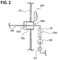
- FIG. 2 is a schematic diagram illustrating a part of a sampling apparatus of another embodiment of the presently disclosed subject matter.
- FIGS. 3A to 3D are diagrams illustrating a procedure for installation of an aseptic sampling flow path kit in the aseptic sampling apparatus of the embodiment of the presently disclosed subject matter.
- FIG. 1 is a schematic diagram of a sampling apparatus 1 of an embodiment of the presently disclosed subject matter.
- the sampling apparatus 1 may include:
- an isolator 10 which maintains the internal space in an aseptic condition
- liquid delivery port 103 which is disposed in the isolator 10 ;
- sampling section 203 which is disposed inside the isolator 10 ;
- a first flow path 204 which communicates with the sampling section 203 , and which connects the inside and outside of the isolator 10 to each other through the liquid delivery port 103 ;
- At least one one-way valve 205 which is disposed in the first flow path 204 , and which limits flow of fluid in the first flow path 204 to a direction from the sampling section 203 toward the liquid delivery port 103 , wherein a part of the first flow path 204 includes a germicidal unit 30 .
- the isolator 10 is an apparatus which has an aseptic operation area that is completely physically isolated from direct interventions of the environment and an operator. Air filtered by a HEPA filter or an ULPA filter is supplied into the isolator after decontamination to be continuously used while preventing risk of contamination from the external environment.
- the isolator 10 in FIG. 1 is isolated from the external space by an aseptic chamber 101 , and, although not illustrated, may include a HEPA filter or an ULPA filter. Although not illustrated, the isolator 10 may further include a decontaminating unit which decontaminates the internal space S of the isolator.
- the term “decontamination” means a process of eliminating living microorganisms by a reproducible method, or that of reducing living microorganisms to a pre-designated level.
- the decontaminating unit is a unit which is used for realizing “decontamination.”
- a unit using a decontamination agent that performing a plasma process, that using gamma rays, or that using ultraviolet rays may be employed as the decontaminating unit, but the decontaminating unit is not limited to such units.
- a unit using a decontamination agent may be used.
- the decontamination agent are mist or vapor of hydrogen peroxide or peracetic acid, an ozone gas, a chlorine dioxide gas, and an ethylene oxide gas.
- a liquid delivery port body 103 c is disposed in the aseptic chamber 101 which isolates the inside and outside of the isolator 10 from each other.
- the liquid delivery port body 103 c may have a cylindrical shape, or a hollow rectangular parallelepiped shape. The shape of the liquid delivery port body is not particularly limited.
- the inside and outside of the aseptic chamber 101 communicate with each other through the liquid delivery port body 103 c .
- a liquid delivery port inner lid 103 a and a liquid delivery port outer lid 103 b can be fitted to liquid delivery port openings 1031 , 1030 of the liquid delivery port body 103 c , respectively to hermetically seal the liquid delivery port openings 1031 , 1030 .
- the liquid delivery port 103 may include at least the liquid delivery port inner lid 103 a , the liquid delivery port outer lid 103 b , and the liquid delivery port body 103 c .
- the first flow path 204 is passed through the liquid delivery port inner lid 103 a .
- the portion of the liquid delivery port inner lid 103 a through which the first flow path 204 is passed is sealed by a sealing member or the like so that the fluid does not leak.
- the first flow path 204 communicates with the sampling section 203 .
- the sample or buffer solution 202 supplied to the sampling section 203 passes through the first flow path 204 that communicates with a bottom portion of the sampling section 203 , and is then discharged.
- the first flow path 204 may include at least one one-way valve 205 which limits flow of the fluid in the first flow path 204 to a direction from the sampling section 203 toward the liquid delivery port 103 . This can prevent the fluid from reversely flowing into the internal space S of the isolator.
- the sampling section 203 is made of a material which is resistant to a sterilizing process.
- a metal for example, stainless steel
- polyethylene for example, polypropylene, polycarbonate, polystyrene, polyvinyl chloride, nylon, polyurethane, polyurea, polylactate, polyglycolic acid, polyvinyl alcohol, polyvinyl acetate, poly(meta)acrylic acid, a poly(meta)acrylic acid derivative, polyacrylonitrile
- the first flow path 204 may include a germicidal flow path 2040 to which the germicidal unit 30 is applicable.
- the germicidal unit 30 means a unit which can eliminate living microorganisms, or reduce living microorganisms to a pre-designated level.
- a germicidal unit 30 that uses radiation for example, gamma rays
- electron beams for example, electron beams
- ultraviolet rays or heat
- Gamma rays are emitted when 60 Co, 137 Cs, or the like undergoes gamma decay.
- the germicidal unit 30 which uses gamma rays can damage biopolymer (particularly, DNA), and kill microorganisms.
- the germicidal unit 30 which uses electron beams is a unit that can damage biopolymer (particularly, DNA), and kill microorganisms.
- the germicidal unit 30 is a unit which applies heat to kill microorganisms, for example, heating to 80° C. or higher, 90° C. or higher, 100° C. or higher, 110° C. or higher, 120° C. or higher, 130° C. or higher, 140° C. or higher, or 150° C. or higher can be applied to perform sterilization.
- ultraviolet rays can damage biopolymer (particularly, DNA) of microorganisms, and kill the microorganisms.
- the wavelength of ultraviolet rays which is useful in the germicidal unit 30 in the presently disclosed subject matter is preferably a deep ultraviolet wavelength, 200 to 350 nm, more preferably 230 to 330 nm, and further preferably 250 to 300 nm.
- Ultraviolet rays which are useful in the germicidal unit 30 may be generated by using a known light source.
- ultraviolet rays can be generated by using a light emitting diode (LED) which emits light at a deep ultraviolet wavelength.
- LED light emitting diode
- the germicidal unit 30 can be miniaturized, and easily attached and detached.
- the germicidal unit 30 using an LED which emits light at a deep ultraviolet wavelength is preferred.
- the germicidal flow path 2040 is preferably formed by a material which does not prevent the disinfection effect from being exerted in the germicidal flow path 2040 , and to which biological materials are hardly adsorbed. Such a material may be appropriately selected in accordance with the used germicidal unit 30 .
- the germicidal flow path 2040 which does not disturb transmission of gamma rays or electron beams, and which is less deteriorated by gamma rays or electron beams may be used, and a tube which is conventionally used as a medical tube (e.g., a silicone rubber tube, a polyethylene tube, or a polyimide tube) may be employed.
- a medical tube e.g., a silicone rubber tube, a polyethylene tube, or a polyimide tube
- the germicidal unit 30 is a unit which applies heat to perform sterilization
- a silicone rubber tube, a metal-made tube, a polyimide tube, a fluorine resin tube, or the like may be used as the germicidal flow path 2040 .
- a tube made of a material which does not disturb transmission of ultraviolet rays, and to which biological materials are hardly adsorbed such as a fluorine resin tube (a PTFE tube, an FEP tube, a THV tube, a PFA tube, an ETFE tube, or a PVDF tube) may be employed.
- a fluorine resin tube a PTFE tube, an FEP tube, a THV tube, a PFA tube, an ETFE tube, or a PVDF tube
- an FEP tube may be employed.
- the inner diameter, thickness, and the like of the germicidal flow path 2040 may be adequately selected in accordance with the germicidal unit 30 .
- a part of the first flow path 204 may be the germicidal flow path 2040 , or the whole first flow path 204 may be the germicidal flow path 2040 .
- the flow path is coupled by known connectors.
- the germicidal flow path 2040 may be placed downstream of the liquid delivery port 103 , or downstream of a liquid delivery port inner lid 103 a .
- the application of the germicidal unit 30 to the periphery of the germicidal flow path 2040 causes microorganisms to be dead downstream of the liquid delivery port 103 , or downstream of the liquid delivery port inner lid 103 a , whereby the interior of the isolator can be prevented from being contaminated.
- the first flow path 204 may be directly coupled to a waste liquid tank 308 , or alternatively provided with an aseptic connection coupling 207 in the middle of the flow path.
- an aseptic connection coupling (male type) 207 a and another aseptic connection coupling (female type) 207 b are combined with each other, membrane strips 2070 which hermetically seal openings of the aseptic connection coupling (male type) 207 a and the aseptic connection coupling (female type) 207 b , respectively are pulled and peeled off, and the aseptic connection coupling (male type) 207 a and the aseptic connection coupling (female type) 207 b are locked with each other, whereby the couplings can be aseptically coupled to each other.
- the aseptic connection coupling 207 a commercially available one can be used.
- the coupling is available from Pall Corporation (USA), Sartorius AG (Germany), Colder Products Company (USA), or the like.
- the aseptic connection coupling (male type) 207 a and the aseptic connection coupling (female type) 207 b may be exchangeably used.
- the aseptic connection coupling (male type) 207 a or the aseptic connection coupling (female type) 207 b ) is disposed in the middle of the first flow path 204 and downstream of the liquid delivery port inner lid 103 a , the flow path which aseptically connects the inside and outside of the isolator to each other can be minimized.
- the aseptic connection coupling 207 enables the flow path downstream of the aseptic connection coupling 207 to be freely designed.
- the sampling apparatus 1 may further include, in the isolator 10 , a second flow path 206 which communicates with the sampling section 203 , a buffer solution supplying section 201 which supplies the fluid to the second flow path 206 , and a first pump 208 which is disposed in the second flow path 206 .
- the buffer solution 202 is supplied to the sampling section 203 , and the sampling section 203 and the first flow path 204 can be kept clean.
- the buffer solution 202 may be supplied by, for example, a tip 210 .
- the first pump 208 may be a tube pump (peristaltic pump), or a piezoelectric pump, and any type of pump can be used as far as it can send the fluid.
- the buffer solution 202 a solution having characteristics which suppresses a pH variation to a minimum level in order to prevent the properties of materials contained in the sample SP from being changed.
- a liquid culture medium such as DMEM or RPM1-1640
- the kind of the buffer solution 202 may be appropriately selected in accordance with the kind and purpose of the sample SP to be recovered. In place of the buffer solution 202 , water or a physiological saline solution may be used.
- a fourth flow path 302 which is connected to an instrument 311 that detects various components
- a fifth flow path 303 which is connected to the waste liquid tank 308 are formed downstream of the aseptic connection coupling 207
- a second pump 307 and a third pump 312 are disposed in the middles of the fourth flow path 302 and the fifth flow path 303 , respectively
- the fourth flow path 302 and the fifth flow path 303 are opened and closed by a pinch valve switching device 306 so that the fluid flows through one of the fourth and fifth flow paths.
- a first pinch valve 304 is closed, a second pinch valve 305 is simultaneously opened, and the third pump 312 is driven, whereby the buffer solution 202 which is supplied to the sampling section 203 can be flowed in the form of a one-way flow from the first flow path 204 to the waste liquid tank 308 through the fifth flow path 303 .
- the buffer solution 202 is discharged from the sampling section 203 and the first flow path 204 , the second pinch valve 305 is thereafter closed, the first pinch valve 304 is simultaneously opened, the sample SP which is recovered from cultured cells CL in a cell culturing section 209 is ejected into the sampling section 203 by the tip 210 , and the second pump 307 is driven, whereby the sample SP is guided from the first flow path 204 to the fourth flow path 302 , and the instrument 311 is enabled to measure the components and the like.
- the second pump 307 and the third pump 312 may be tube pumps (peristaltic pumps), or piezoelectric pumps, and any types of pumps can be used as far as they can send the fluid.
- the sampling apparatus 1 may further include at least one fluid detecting unit which detects the flow of the fluid in the first flow path 204 .
- the fluid detecting unit may be a unit which detects the flow of the fluid, such as a liquid flow sensor 313 that is disposed in the first flow path 204 .
- the fluid detecting unit may be a sensor which senses the operation of the third pump 312 , or an electronic balance 310 which detects the weight of the waste liquid tank 308 , or may be a combination of these configurations.
- a signal which is detected by the fluid detecting unit is monitored by a CPU unit (in FIG.
- the germicidal unit 30 is caused to operate through a cable 316 (alternatively, communication is conducted through wireless manner). Even in the case where an abnormality occurs in the mechanism which sends the sample from the sterile environment in the isolator into the non-sterile environment, therefore, the sterile environment in the isolator can be prevented from being contaminated, and the safe cell culture environment can be maintained.
- the operation of the germicidal unit 30 is limited in a case where an abnormality occurs in the mechanism which sends the sample from the sterile environment in the isolator 10 into the non-sterile environment, and thereby changes of the biological characteristics of the sample is avoidable as far as possible.
- the fluid detecting unit, the CPU unit, and the germicidal unit 30 are preferably independent from the power supply for the sampling apparatus 1 , and preferably connected to an uninterruptible power system.
- FIG. 2 is a schematic diagram illustrating a part of the sampling apparatus 1 of another embodiment of the presently disclosed subject matter, and illustrating a configuration where the germicidal unit 30 is applied to the first flow path 204 which is upstream of the one one-way valve 205 .
- the germicidal unit 30 may be disposed in any portion of the first flow path 204 as far as the portion has the germicidal flow path 2040 .
- the presently disclosed subject matter further provides the aseptic sampling flow path kit 20 which is to be applied to the isolator 10 having the liquid delivery port 103 , wherein the kit includes:
- the first flow path 204 which communicates with the sampling section 203 , and which connects the inside and outside of the isolator 10 to each other through the liquid delivery port 103 ;
- At least one one-way valve 205 which is disposed in the first flow path 204 , and which limits flow of the fluid in the first flow path 204 to the direction from the sampling section 203 toward the liquid delivery port 103 , and
- the first flow path 204 is the germicidal flow path 2040 to which the germicidal unit 30 is applicable.
- the aseptic sampling flow path kit 20 may further include the second flow path 206 which communicates with the sampling section 203 , the buffer solution supplying section 201 which supplies the fluid to the second flow path 206 , and the first pump 208 which is disposed in the second flow path 206 .
- the aseptic sampling flow path kit 20 may further include an aseptic connection coupling 207 a in the downstream end of the first flow path 204 .
- the above-described members included in the aseptic sampling flow path kit 20 may be enclosed in individual sterilization pouches 200 , respectively, or collectively enclosed in the same sterilization pouch 200 as illustrated in FIG. 3A .
- the members of the aseptic sampling flow path kit 20 which are enclosed in the sterilization pouch 200 are previously sterilized by gamma rays, electron beams, or the like.
- the aseptic sampling flow path kit 20 is carried into the isolator 10 through the openings of the liquid delivery port body 103 c of the isolator, or a decontamination pass box (not shown) which is additionally disposed in the isolator 10 ( FIG. 3A ). Thereafter, the liquid delivery port opening 1030 which is on the outer side is hermetically closed with the liquid delivery port outer lid 103 b , and the interior of the isolator 10 and the aseptic sampling flow path kit 20 are decontaminated ( FIG. 3B ).
- the liquid delivery port inner lid 103 a may be provided in the state where the lid is enclosed in the sterilization pouch 200 as illustrated in FIGS. 3A and 3B , or provided into the isolator 10 separately from the sterilization pouch 200 .
- the sterilization pouch 200 is opened by using gloves 102 into which the arms of the operator are insertable from the outside of the isolator 10 , and the members are assembled.
- the first flow path 204 , the one-way valve 205 , and the aseptic connection coupling (male type) 207 a are placed in the liquid delivery port body 103 c , and the liquid delivery port body is hermetically closed with the liquid delivery port inner lid 103 a through which the first flow path 204 is passed ( FIG. 3C ).
- the liquid delivery port outer lid 103 b is detached, and the first flow path 204 , the one-way valve 205 , and the aseptic connection coupling (male type) 207 a are taken out from the liquid delivery port body 103 c . Thereafter, the coupling is aseptically coupled to the third flow path 301 which has the aseptic connection coupling (female type) 207 b at one end, by using the aseptic connection couplings. After that, the germicidal unit 30 is set at the germicidal flow path 2040 of the first flow path 204 ( FIG. 3D ). With the above setting, the aseptic sampling apparatus 1 of the presently disclosed subject matter using the aseptic sampling flow path kit can be used.
Landscapes
- Life Sciences & Earth Sciences (AREA)
- Health & Medical Sciences (AREA)
- Biochemistry (AREA)
- Physics & Mathematics (AREA)
- Chemical & Material Sciences (AREA)
- Analytical Chemistry (AREA)
- General Health & Medical Sciences (AREA)
- General Physics & Mathematics (AREA)
- Immunology (AREA)
- Pathology (AREA)
- Hydrology & Water Resources (AREA)
- Engineering & Computer Science (AREA)
- Biomedical Technology (AREA)
- Molecular Biology (AREA)
- Apparatus Associated With Microorganisms And Enzymes (AREA)
Abstract
Description
Claims (15)
Applications Claiming Priority (3)
| Application Number | Priority Date | Filing Date | Title |
|---|---|---|---|
| JP2018024393A JP7296566B2 (en) | 2018-02-14 | 2018-02-14 | Sterile sampling channel kit and cell culture device using the same |
| JP2018-024393 | 2018-02-14 | ||
| JPJP2018-024393 | 2018-02-14 |
Publications (2)
| Publication Number | Publication Date |
|---|---|
| US20190250073A1 US20190250073A1 (en) | 2019-08-15 |
| US11320344B2 true US11320344B2 (en) | 2022-05-03 |
Family
ID=67541500
Family Applications (1)
| Application Number | Title | Priority Date | Filing Date |
|---|---|---|---|
| US16/237,888 Active 2039-12-01 US11320344B2 (en) | 2018-02-14 | 2019-01-02 | Aseptic sampling flow path kit and sampling apparatus using the same |
Country Status (2)
| Country | Link |
|---|---|
| US (1) | US11320344B2 (en) |
| JP (1) | JP7296566B2 (en) |
Families Citing this family (7)
| Publication number | Priority date | Publication date | Assignee | Title |
|---|---|---|---|---|
| GB2567797B (en) * | 2017-08-08 | 2021-07-28 | Owlstone Inc | Sensor system |
| JP7296569B2 (en) * | 2018-10-23 | 2023-06-23 | 日本光電工業株式会社 | Sample storage device |
| JP7310258B2 (en) * | 2019-04-19 | 2023-07-19 | 大日本印刷株式会社 | BIOLOGICAL CONTAINER, BIOLOGICAL CONTAINER KIT AND EQUIPMENT CONTAINER |
| JP7526572B2 (en) * | 2020-03-16 | 2024-08-01 | 藤森工業株式会社 | Sampling device, culture device, and method for producing culture |
| WO2022162722A1 (en) * | 2021-01-26 | 2022-08-04 | 株式会社日立ハイテク | Aseptic sampling apparatus and aseptic sampling method |
| CN120359288A (en) * | 2022-12-19 | 2025-07-22 | 大幸药品株式会社 | Chlorine dioxide concentration control system |
| CN116952640A (en) * | 2023-07-11 | 2023-10-27 | 中检溯源江苏技术服务有限公司 | Food detection safe quick sterile sampling equipment |
Citations (4)
| Publication number | Priority date | Publication date | Assignee | Title |
|---|---|---|---|---|
| US20120252110A1 (en) * | 2011-03-28 | 2012-10-04 | Tokyo Women's Medical University | Cell culture apparatus |
| US20130183678A1 (en) * | 2010-07-16 | 2013-07-18 | Vanderbilt University | Low resource processor using surface tension valves for extracting, concentrating and detecting molecular species |
| US20150079655A1 (en) * | 2013-09-17 | 2015-03-19 | Covaris, Inc. | Method and apparatus for processing sample material |
| JP2017185218A (en) | 2016-03-31 | 2017-10-12 | 旭化成メディカル株式会社 | Blood purification device and sterilization method |
Family Cites Families (1)
| Publication number | Priority date | Publication date | Assignee | Title |
|---|---|---|---|---|
| SE0001278L (en) | 2000-04-06 | 2001-10-08 | Peter Unger Med P U Med Konsul | sterile Coupling |
-
2018
- 2018-02-14 JP JP2018024393A patent/JP7296566B2/en active Active
-
2019
- 2019-01-02 US US16/237,888 patent/US11320344B2/en active Active
Patent Citations (5)
| Publication number | Priority date | Publication date | Assignee | Title |
|---|---|---|---|---|
| US20130183678A1 (en) * | 2010-07-16 | 2013-07-18 | Vanderbilt University | Low resource processor using surface tension valves for extracting, concentrating and detecting molecular species |
| US20120252110A1 (en) * | 2011-03-28 | 2012-10-04 | Tokyo Women's Medical University | Cell culture apparatus |
| JP2012200239A (en) | 2011-03-28 | 2012-10-22 | Nippon Koden Corp | Cell culture apparatus |
| US20150079655A1 (en) * | 2013-09-17 | 2015-03-19 | Covaris, Inc. | Method and apparatus for processing sample material |
| JP2017185218A (en) | 2016-03-31 | 2017-10-12 | 旭化成メディカル株式会社 | Blood purification device and sterilization method |
Non-Patent Citations (1)
| Title |
|---|
| Office Action dated Jan. 25, 2022 by the Japanese Patent Office in counterpart Japanese Patent English Application No. 2018-024393. |
Also Published As
| Publication number | Publication date |
|---|---|
| JP2019136005A (en) | 2019-08-22 |
| US20190250073A1 (en) | 2019-08-15 |
| JP7296566B2 (en) | 2023-06-23 |
Similar Documents
| Publication | Publication Date | Title |
|---|---|---|
| US11320344B2 (en) | Aseptic sampling flow path kit and sampling apparatus using the same | |
| CN107137741A (en) | The bio-indicator of separate sets | |
| US12161771B2 (en) | Apparatus and method for sterilization of an article | |
| US11505774B2 (en) | Sample storage apparatus | |
| US11946034B2 (en) | Sterile sampling apparatus | |
| KR20010062653A (en) | Dry booster | |
| US11318456B2 (en) | Aseptic sampling apparatus and sampling method using the same | |
| JP5278861B2 (en) | CO2 incubator ozone sterilizer | |
| EP3897506A2 (en) | Biological indicator for liquid-chemical sterilization system | |
| US12292487B2 (en) | Cleaning of a fluid path for hyperpolarization of a pharmaceutical product | |
| Rogers | Healthcare Sterilisation: Challenging Practices, Volume 2 | |
| Maillard et al. | Sterilization in practice | |
| US20230338596A1 (en) | Sterilization apparatus | |
| KR200490394Y1 (en) | Supply cable for hydrogen peroxide sterilizer | |
| Walsh | Sterilization in practice |
Legal Events
| Date | Code | Title | Description |
|---|---|---|---|
| AS | Assignment |
Owner name: NIHON KOHDEN CORPORATION, JAPAN Free format text: ASSIGNMENT OF ASSIGNORS INTEREST;ASSIGNORS:MAKINO, HODAKA;KUBO, HIROTSUGU;KINOOKA, MASAHIRO;SIGNING DATES FROM 20181213 TO 20181217;REEL/FRAME:047882/0415 Owner name: OSAKA UNIVERSITY, JAPAN Free format text: ASSIGNMENT OF ASSIGNORS INTEREST;ASSIGNORS:MAKINO, HODAKA;KUBO, HIROTSUGU;KINOOKA, MASAHIRO;SIGNING DATES FROM 20181213 TO 20181217;REEL/FRAME:047882/0415 |
|
| FEPP | Fee payment procedure |
Free format text: ENTITY STATUS SET TO UNDISCOUNTED (ORIGINAL EVENT CODE: BIG.); ENTITY STATUS OF PATENT OWNER: LARGE ENTITY |
|
| STPP | Information on status: patent application and granting procedure in general |
Free format text: NON FINAL ACTION MAILED |
|
| STPP | Information on status: patent application and granting procedure in general |
Free format text: RESPONSE TO NON-FINAL OFFICE ACTION ENTERED AND FORWARDED TO EXAMINER |
|
| STPP | Information on status: patent application and granting procedure in general |
Free format text: FINAL REJECTION MAILED |
|
| STPP | Information on status: patent application and granting procedure in general |
Free format text: ADVISORY ACTION MAILED |
|
| STPP | Information on status: patent application and granting procedure in general |
Free format text: DOCKETED NEW CASE - READY FOR EXAMINATION |
|
| STPP | Information on status: patent application and granting procedure in general |
Free format text: NON FINAL ACTION MAILED |
|
| STPP | Information on status: patent application and granting procedure in general |
Free format text: NOTICE OF ALLOWANCE MAILED -- APPLICATION RECEIVED IN OFFICE OF PUBLICATIONS |
|
| STPP | Information on status: patent application and granting procedure in general |
Free format text: PUBLICATIONS -- ISSUE FEE PAYMENT VERIFIED |
|
| STCF | Information on status: patent grant |
Free format text: PATENTED CASE |
|
| MAFP | Maintenance fee payment |
Free format text: PAYMENT OF MAINTENANCE FEE, 4TH YEAR, LARGE ENTITY (ORIGINAL EVENT CODE: M1551); ENTITY STATUS OF PATENT OWNER: LARGE ENTITY Year of fee payment: 4 |