WO2023100590A1 - 要推定領域推定システム、要推定領域推定プログラム、および要推定領域推定方法 - Google Patents
要推定領域推定システム、要推定領域推定プログラム、および要推定領域推定方法 Download PDFInfo
- Publication number
- WO2023100590A1 WO2023100590A1 PCT/JP2022/041182 JP2022041182W WO2023100590A1 WO 2023100590 A1 WO2023100590 A1 WO 2023100590A1 JP 2022041182 W JP2022041182 W JP 2022041182W WO 2023100590 A1 WO2023100590 A1 WO 2023100590A1
- Authority
- WO
- WIPO (PCT)
- Prior art keywords
- estimation
- area
- estimated
- unit
- detected
- Prior art date
Links
- 238000000034 method Methods 0.000 title claims description 15
- 238000001514 detection method Methods 0.000 claims abstract description 35
- 230000000295 complement effect Effects 0.000 abstract description 3
- 238000004458 analytical method Methods 0.000 description 23
- 230000006399 behavior Effects 0.000 description 23
- 238000003384 imaging method Methods 0.000 description 15
- 238000004891 communication Methods 0.000 description 14
- 238000010586 diagram Methods 0.000 description 9
- 230000006870 function Effects 0.000 description 8
- 238000010801 machine learning Methods 0.000 description 4
- 230000007547 defect Effects 0.000 description 3
- 238000005516 engineering process Methods 0.000 description 3
- 210000003127 knee Anatomy 0.000 description 3
- 238000004519 manufacturing process Methods 0.000 description 3
- 230000005540 biological transmission Effects 0.000 description 2
- 238000013135 deep learning Methods 0.000 description 2
- 238000009434 installation Methods 0.000 description 2
- 230000033001 locomotion Effects 0.000 description 2
- 230000035945 sensitivity Effects 0.000 description 2
- 238000012706 support-vector machine Methods 0.000 description 2
- 230000001133 acceleration Effects 0.000 description 1
- 210000003423 ankle Anatomy 0.000 description 1
- 238000013528 artificial neural network Methods 0.000 description 1
- 230000007423 decrease Effects 0.000 description 1
- 210000005069 ears Anatomy 0.000 description 1
- 230000000694 effects Effects 0.000 description 1
- 239000004973 liquid crystal related substance Substances 0.000 description 1
- 229910044991 metal oxide Inorganic materials 0.000 description 1
- 150000004706 metal oxides Chemical class 0.000 description 1
- 238000007637 random forest analysis Methods 0.000 description 1
- 239000004065 semiconductor Substances 0.000 description 1
- 230000001502 supplementing effect Effects 0.000 description 1
- 210000000707 wrist Anatomy 0.000 description 1
Images


Classifications
-
- G—PHYSICS
- G06—COMPUTING; CALCULATING OR COUNTING
- G06T—IMAGE DATA PROCESSING OR GENERATION, IN GENERAL
- G06T7/00—Image analysis
Definitions
- the present invention relates to an estimation-required area estimation system, an estimation-required area estimation program, and an estimation-required area estimation method.
- Patent Document 1 discloses the following technology. Based on the image information acquired by cameras fixedly installed in the facility, the human skeleton is estimated by machine learning. Then, when the worker is hidden in the blind spot of the camera, the estimated skeleton is corrected using sensor information from a worker terminal such as a first-person viewpoint camera attached to the worker or an acceleration sensor. As a result, even if a part of the image of the person cannot be obtained, it is possible to grasp the detailed movements of the person and provide appropriate operation support to the worker.
- a worker terminal such as a first-person viewpoint camera attached to the worker or an acceleration sensor.
- Patent Literature 1 requires the worker to wear the terminal, so there is a problem that the cost increases and the work efficiency decreases due to the terminal installation. In addition, there is a problem that new learning is required when joints or regions to be estimated are added.
- An object of the present invention is to provide an area estimation program and an estimation-required area estimation method.
- An estimation-required region estimation system having a detection unit that detects joint points of an object from an image of the object, and an estimation unit that estimates an estimation-required region based on the joint points detected by the detection unit.
- a determination unit that determines whether or not the estimation required area exists based on the detected joint points, and the estimation unit determines the estimation required area when it is determined that the estimation required area does not exist.
- a correction unit for estimating and correcting the joint points by interpolating the detected joint points with the estimated area to be estimated; and a color belonging to the object based on the estimated area to be estimated.
- a correction unit that corrects the joint points by interpolating the detected joint points in the estimated estimation required area; a reception unit that receives designation of a color information acquisition area;
- estimation-required region estimation system according to any one of (1) to (6) above, further comprising an image acquisition unit that acquires the image.
- a behavior estimation unit that estimates the behavior of the object based on the corrected joint points; and specific information that individually identifies the object based on the color information acquired by the color information acquisition unit. and an output unit for outputting the behavior estimated by the behavior estimation unit and the specific information determined by the specific information determination unit in association with each object.
- step (b) the estimation-required region in the frame in which the joint point is detected is estimated based on the joint point detected in the frame of the image. Estimated area estimation program.
- the processing includes a step (c) of determining whether or not the estimation-required region exists based on the detected joint points, and in the step (b), it is determined that the estimation-required region does not exist. if so, estimating the region to be estimated, the processing includes a step (d) of correcting the joint points by interpolating the detected joint points with the estimated region to be estimated; (12) or (13), further comprising a step (e) of obtaining color information belonging to the object from the image based on the estimated area to be estimated.
- step (b) The above-described (15), wherein in step (b), the estimation-required region in the frame in which the joint point is detected is estimated based on the joint point detected in the frame of the image. Estimation required area estimation method.
- FIG. 4 shows schematic structure of an analysis system. It is a block diagram which shows the hardware constitutions of an analysis apparatus. 4 is a block diagram showing functions of a control unit of the analysis device; FIG. FIG. 4 is an explanatory diagram showing a method of estimating an estimation required area; It is a flow chart which shows operation of an analysis device. 4 is a block diagram showing functions of a control unit of the analysis device; FIG.
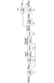
- FIG. 1 is a diagram showing a schematic configuration of an analysis system 10. As shown in FIG. The analysis system 10 constitutes an estimation required area estimation system.
- the analysis system 10 includes an analysis device 100, an imaging device 200, and a communication network 300.
- the analysis device 100 is connected to the imaging device 200 via a communication network 300 so as to be able to communicate with each other.
- the analysis system 10 can be configured only with the analysis device 100 .
- the imaging device 200 constitutes an image acquisition unit.
- the analysis device 100 detects the joint points 410 (see FIG. 4) of the object included in the captured image received from the imaging device 200, estimates an estimation required region described later based on the joint points 410, and estimates the estimated estimation required region.
- the joint point 410 is corrected by complementing the joint point 410 with .
- the analysis device 100 estimates the behavior of the object based on the corrected joint points 410, and determines specific information that individually identifies the object based on the obtained color information of the estimation-required area.
- the object may be an articulated object such as a person. In the following, for the sake of simplicity, the object is assumed to be a human subject 400 (see FIG. 4).
- the photographing device 200 is configured by, for example, a near-infrared camera, is installed at a predetermined position, and photographs the photographing area from the predetermined position.
- the imaging device 200 irradiates a near-infrared light toward an imaging area with an LED (Light Emitting Device), and receives near-infrared light reflected by an object in the imaging area with a CMOS (Complementary Metal Oxide Semiconductor) sensor. , the imaging area can be photographed.
- the captured image may be a monochrome image in which each pixel has a reflectance of near-infrared rays.
- the predetermined position may be, for example, the ceiling of the manufacturing plant where the subject 400 works as a worker.
- the imaging area can be, for example, a three-dimensional area that includes the entire floor of a manufacturing plant.
- the photographing device 200 can photograph the photographing area as a moving image composed of a plurality of photographed images (frames) at a frame rate of 15 fps to 30 fps, for example.
- a network interface based on a wired communication standard such as Ethernet (registered trademark) can be used for the communication network 300 .
- the communication network 300 may use a network interface based on wireless communication standards such as Bluetooth (registered trademark) and IEEE802.11.
- FIG. 2 is a block diagram showing the hardware configuration of the analysis device 100.
- Analysis device 100 includes control unit 110 , storage unit 120 , communication unit 130 , and operation display unit 140 . These components are interconnected via bus 150 .
- Analysis device 100 may be configured by a computer.
- the control unit 110 is composed of a CPU (Central Processing Unit), and performs control and arithmetic processing of each unit of the analysis device 100 according to a program. Details of the functions of the control unit 110 will be described later.
- CPU Central Processing Unit
- the storage unit 120 can be composed of RAM (Random Access Memory), ROM (Read Only Memory), and flash memory.
- the RAM temporarily stores programs and data as a work area for the control unit 110 .
- the ROM stores various programs and various data in advance.
- the flash memory stores various programs including an operating system and various data.
- the communication unit 130 is an interface for communicating with external devices.
- Network interfaces conforming to standards such as Ethernet (registered trademark), SATA, PCI Express, USB, and IEEE1394 can be used for communication.
- wireless communication interfaces such as Bluetooth (registered trademark), IEEE802.11, and 4G can be used for communication.
- the communication unit 130 receives the captured image from the imaging device 200 .
- the operation display unit 140 is composed of, for example, a liquid crystal display, a touch panel, and various keys.
- the operation display unit 140 receives various operations and inputs, and displays various information.
- control unit 110 The function of the control unit 110 will be explained.
- FIG. 3 is a block diagram showing functions of the control unit 110 of the analysis device 100.
- Control unit 110 functions as position detection unit 111, loss determination unit 112, estimation unit 113, correction unit 114, color information acquisition unit 115, behavior estimation unit 116, and individual determination unit 117 by executing programs.
- the position detection unit 111 constitutes a detection unit.
- the loss determination unit 112 constitutes a determination unit.
- the individual determination unit 117 constitutes a specific information determination unit.
- Action estimation unit 116 and individual determination unit 117 constitute an output unit.
- the position detection unit 111 detects joint points 410 of the subject 400 from the captured image of the object. Specifically, the position detection unit 111 detects the joint point 410, for example, as coordinates of a pixel in the captured image. When a plurality of subjects 400 are included in the captured image, the position detection unit 111 detects the joint point 410 for each subject 400 . For the sake of simplicity, it is assumed that there is only one target person 400 included in the photographed image.
- the position detection unit 111 detects the joint point 410 by estimating it from the captured image using machine learning.
- the position detection unit 111 can detect the joint point 410 using known deep learning such as Deep Pose, CNN (Convolution Neural Network), and Res Net.
- the position detection unit 111 may detect the joint point 410 using machine learning other than deep learning, such as SVM (Support Vector Machine) and Random Forest.
- Joint points 410 may include, for example, the head, nose, neck, shoulders, elbows, wrists, hips, knees, ankles, eyes, and ears. A case where the joint points 410 detected by the position detection unit 111 are five joint points 410 of the neck, shoulders (right shoulder and left shoulder), and hips (right hip and left hip) will be described below as an example.
- the position detection unit 111 calculates the likelihood for each pixel of the captured image for each class of the joint point 410 of the subject 400 (classification of the joint point 410 such as left shoulder, right shoulder, left hip, etc.). Pixels that have a likelihood can be detected as articulation points 410 . Therefore, a pixel with a likelihood lower than the predetermined threshold is not detected as the joint point 410 . Therefore, part of the joint point 410 may not be detected depending on the degree of clarity of the image of the subject 400 in the captured image, the influence of occlusion, and the like.
- the missing determination unit 112 determines whether or not there is a missing joint point 410 or the like due to a part of the joint point 410 not being detected (estimated) for some reason. 410 to determine. Specifically, loss determining section 112 determines whether or not there are joint points 410 that have not been detected and/or regions that include joint points 410 and that need to be estimated (hereinafter referred to as “estimation-required regions”). judge.
- the presence of the estimation-required region corresponds to the presence of a defect such as the joint point 410 . Absence of the estimation-required region corresponds to absence of defects such as joint points 410 .
- the area including the joint point 410 is, for example, a square area of a predetermined size centered on the joint point 410 .
- the estimation required area can be set in advance.
- the estimation-required area includes (1) an area that could not be obtained (detected) due to the installation position of the imaging device 200, and (2) an area that is not originally planned to be detected (acquired) by the position detection unit 111. (an area not set to be detected by the position detection unit 111).
- the missing determination unit 112 determines, for example, the class of the joint points 410 of the subject 400 detected by the position detection unit 111 (classification of joint points such as the left shoulder, right shoulder, and left hip) and necessary joint points 410 (hereinafter referred to as simply referred to as "necessary joint points"), it is determined whether or not there is an estimation required region.
- the necessary joint points include (a) the joint points 41 set to be detected by the position detection unit 111 0 and (b) a joint point 410 that is not set to be detected by the position detection unit 111 but is necessary for acquiring color information described later.
- the loss determination unit 112 determines that the joint points 410 set to be detected by the position detection unit 111 include the joint point 410 of the “left shoulder” and the joint points 410 detected by the position detection unit 111 are detected. If the "left shoulder" joint point 410 is not included in the point 410, the "left shoulder” joint point 410 corresponds to the region requiring estimation in (1) above, so it is determined that there is a region requiring estimation.
- the necessary joint points are not set to be detected by the position detection unit 111 corresponding to (b) above, but the joint points 410 necessary for obtaining color information are included, the color information
- the joint point 410 or a region including the joint point 410 (hereinafter also referred to as a “specific region”) necessary for obtaining is the estimation required region. This is because the specific region corresponds to the region requiring estimation in (2) above. Therefore, when there is a specific region, the loss determination unit 112 determines that there is an estimation required region.
- the specific region includes the “head” joint point 410a (see FIG. 4) or the head region 410s including the “head” joint point 410a.
- the estimating unit 113 estimates an estimation required region based on the joint points 410 detected by the position detecting unit 111 . More specifically, the estimation unit 113 estimates the estimation-required region based on the joint points 410 detected by the position detection unit 111 and the loss determination result by the loss determination unit 112 . Specifically, the estimating unit 113 estimates the estimation-required area when it is determined that there is no estimation-required area in the loss determination result.
- the loss determination result by the loss determination unit 112 may include information specifying the presence or absence of an estimation required region and the estimation required region determined to be absent. Note that if there is information specifying an estimation required area determined to be absent in the loss determination result, the presence or absence of the estimation required area can be omitted. This is because it can be determined that there is an estimation required area if information specifying the estimation required area determined to be absent is included in the loss determination result.
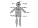
- FIG. 4 is an explanatory diagram showing a method of estimating the estimation required area.
- the image of the target person 400 in the captured image is shown as a gray shape for ease of explanation.
- the head area 410s which is the specific area, is the estimation required area.
- the estimation-required region may be other than the head region 410s. That is, the estimation-required region can be any joint point 410 and a region containing any joint point 410 .
- the estimation required area is assumed to be the head area 410s including the joint points 410a of the "head", which is the specific area, unless otherwise specified.
- the "head” joint point 410a can be estimated, for example, by calculating from the "right shoulder” joint point 410c, the "right hip” joint point 410d, and the "neck” joint point 410b. Specifically, a vector (Lu) is calculated with the starting point at the "right hip” joint point 410d and the ending point at the "right shoulder” joint point 410c. A vector (Lu/2) whose starting point is the joint point 410b of the "neck” is calculated with half the size of the vector (Lu). As a result, the joint point 410a of the "head” is calculated as the end point of the vector (Lu/2).
- a head region 410s which is a square range whose center is the joint point 410a of the "head” and whose length of one side is 1/3 of the size of the vector (Lu), is calculated (estimated) as an estimation required region.
- the region to be estimated is defined by the upper left coordinates, where u is 1/6 of the magnitude of the vector (Lu) (upper body vector), and (x, y) is the coordinates of the joint point 410a of the "head”. It can be calculated (estimated) as a square range with (xu, yu) and the lower right coordinate as (x+u, y+u).
- the estimation-required region may be estimated by machine learning based on the "right shoulder” joint point 410c, the "right waist” joint point 410d, and the “neck” joint point 410b.
- the estimation-required region may be estimated based on the joint points 410 other than the "right shoulder” joint point 410c, the "right waist” joint point 410d, and the "neck” joint point 410b.
- the estimation unit 113 can switch the size of the estimation required area according to the estimation required area.
- the color information acquisition unit 115 acquires the color information of the estimation required area
- the individual determination unit 117 determines the target person 400 based on the color information. This is because, when the target person 400 wears a hat or the like with a color that can identify the individual, the individual target person 400 can be identified by acquiring the color information of the head region 410s, which is the estimation-required region. . For this reason, by switching the size of the estimation-required region according to the size and range of a specific object worn by the target person 400 and by which the target person 400 can identify an individual, the color of the specific object can be changed. By improving the detection sensitivity, it is possible to improve the accuracy of identifying the target person 400 individually.
- the correction unit 114 corrects the joint points 410 detected by the position detection unit 111 by interpolating the joint points 410 detected by the position detection unit 111 with the estimation required area estimated by the estimation unit 113 .
- the color information acquisition unit 115 acquires the color information of the estimation-required region included in the joint points 410 corrected by the correction unit 114 from the captured image as the color information belonging to the subject 400 (object).
- the color information is, for example, the average of pixel values included in the estimation-required area in the captured image.
- the area from which color information is acquired by the color information acquisition unit 115 is not limited to the estimation required area.
- the color information acquisition unit 115 may acquire the color information of the arbitrary joint point 410 or the color information of the area including the arbitrary joint point 410 from the captured image.
- the joint point 410 from which color information is to be obtained or the area including the joint point 410 can be set in advance by storing in the storage unit 120 or the like.
- the behavior estimation unit 116 estimates the behavior of the subject 400 based on the joint points 410 corrected by the correction unit 114 .
- the behavior estimating unit 116 can estimate the behavior of the subject 400, for example, based on the difference in posture due to the joint points 410 estimated for each of the frames of the captured images that are adjacent in time series.
- the difference may be an average or a sum of the differences for each corresponding joint point 410 of the joint points 410 respectively estimated for a plurality of captured image frames adjacent in time series.
- a fall motion may be estimated by the fact that the difference in posture due to the joint point 410 becomes almost zero after the difference in posture exceeds a predetermined threshold.
- the behavior estimation unit 116 can estimate the behavior of the subject 400 based on the corrected joint points 410 using any known behavior estimation method.
- the individual determination unit 117 determines the target person 400 based on the color information acquired by the color information acquisition unit 115 . Determining the individual subject 400 based on the color information corresponds to determining specific information that identifies the subject 400 (object) based on the color information. Specific information includes, for example, information that can identify an individual, such as a name. Specifically, for example, the individual determination unit 117 refers to a table in which the color information and the name of the subject, which corresponds to the specific information, are associated with each other. By specifying the name of the target person 400 individual.
- the target person 400 By acquiring the color information of the head region 410s, which is the region to be estimated, as the color information, for example, when the target person 400 wears a cap of a color that can identify the individual, the target person 400 individuals can be judged.
- the region from which the color information acquisition unit 115 acquires color information is the region including the joint point 410 of the “elbow”. By doing so, the individual 400 subjects can be determined based on the color information. Further, when the color of the work clothes worn by the subject 400 on the lower half of the body is a color that can identify an individual, the region from which the color information acquisition unit 115 acquires color information is the region including the joint point 410 of the “knee”. By doing so, the individual 400 subjects can be determined based on the color information.
- the behavior estimation unit 116 and the individual determination unit 117 can output the behavior estimation result and the determination result of the target person 400 in association with each other for each target person 400 . This makes it possible to grasp the behavior of each of the 400 individual subjects.
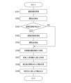
- FIG. 5 is a flow chart showing the operation of the analysis device 100. As shown in FIG. This flowchart can be executed by the control unit 110 of the analysis device 100 according to a program. step S1 02 to S107 can be executed for each frame of the captured image.
- the control unit 110 acquires the captured image by receiving it from the imaging device 200 (S101).
- the control unit 110 detects the joint points 410 of the subject 400 from the captured image (S102).
- the control unit 110 determines whether there is an estimation required area (S103). For example, the control unit 110 compares the class of the detected joint point 410 with the class of the required joint point, and if the class of the detected joint point 410 does not have a part of the class of the required joint point, It is determined that there is an estimation required area in .
- control unit 110 determines that there is no region requiring estimation (S103: NO), it executes step S106.
- control unit 110 determines that there is an estimation required area (S103: YES), it estimates the estimation required area (S104).
- the control unit 110 corrects the detected joint point 410 by complementing it with the estimated area requiring estimation (S105).
- the control unit 110 acquires color information from the captured image (S106). If there is an estimation required area, the control unit 110 can acquire the color information of the estimated estimation required area from the captured image. If there is no estimation-required region, the control unit 110 can acquire the preset joint point 410 from which color information is to be acquired or the color information of the region including the joint point 410 from the captured image.
- the control unit 110 determines the target person 400 from the acquired color information (S107).
- the control unit 110 determines the behavior of the subject 400 based on the corrected joint points 410 in step S105 (S108).
- the control unit 110 associates the determined individual with the action and outputs (S109).
- the output may include transmission to an external device, transmission without specifying a destination, display on the operation display unit 140 or the like, and the like.
- FIG. 6 is a block diagram showing functions of the control unit 110 of the analysis device 100. As shown in FIG. By executing a program, control unit 110 performs position detection unit 111, loss determination unit 112, estimation unit 113, correction unit 114, color information acquisition unit 115, behavior estimation unit 116, individual determination unit 117, reception unit 118, and functions as a switching unit 119 .
- the accepting unit 118 accepts the specification of the color acquisition area input to the operation display unit 104 by the user.
- a color acquisition area is an area from which color information is acquired by the color information acquisition unit 115 .
- the specification of the color acquisition area can be specified by the joint point 410 (for example, the joint point 410 c of the “right shoulder”) or the area including the joint point 410 .
- the color acquisition area can be the coordinates corresponding to the joint points 410 or an area of a predetermined size including the coordinates corresponding to the joint points 410 .
- the color information acquisition unit 115 identifies the color acquisition area based on the specification of the color acquisition area, and acquires the color information of the identified color acquisition area from the captured image.
- the switching unit 119 generates switching information for switching the size of the color acquisition region based on the specified color acquisition region, and determines the size of the color acquisition region for which the color information acquisition unit 115 acquires color information from the captured image. switch between Specifically, the switching unit 119 changes the size of the color acquisition area based on the specified color acquisition area by referring to a table in which the color acquisition area and the size of the color acquisition area are associated with each other, for example. switch.
- the relationship between the color acquisition area and the size of the color acquisition area can be appropriately set according to the size and range of work clothes, a name tag, or the like that is worn by the subject 400 and has an identifiable color.
- the color acquisition area can be set to any area. can be obtained. For example, if the target person 400 is wearing a cap of a color that can identify the individual, the color information of the cap can be obtained by specifying the joint point 410 of the "head" as the color acquisition area. can be If the color of the work clothes worn by the subject 400 on the upper body is a color that can identify an individual, by specifying the joint point 410 of the "elbow" as the color acquisition area, the color information of a hat or the like is acquired as the color information.
- the color information of a hat or the like can be obtained by specifying the joint point 410 of the "knee" as the color acquisition area. can be obtained.
- the embodiment has the following effects.
- an estimation-required region is estimated in the frame in which the joint points are detected. This makes it possible to estimate the estimation-required area more easily.
- the estimation required area is estimated.
- the joint points are corrected by interpolating the detected joint points with the estimated area to be estimated. Then, based on the estimated estimation required area, color information belonging to the object is acquired from the image. As a result, the accuracy of estimating the behavior of the object can be improved, and the color information belonging to the object can be obtained easily and with high accuracy.
- the joint points are corrected, the specification of the color information acquisition area is received, and based on the specification of the color information acquisition area, Accompanying color information is obtained from the image. As a result, it is possible to improve the accuracy of estimating the behavior of the object, and to acquire the color information belonging to the object flexibly and easily.
- the size of the estimation required area is switched according to the estimation required area. As a result, the object identification sensitivity based on color information can be improved.
- the estimation required area be the joint point or the area containing the joint point. This makes it possible to easily and appropriately estimate the estimation-required region.
- it has an image acquisition unit that acquires an image.
- joint points can be detected with high accuracy using an appropriate image.
- the object included in the image be an object with joints.
- detection accuracy can be improved while expanding the detection target of joint points.
- the region to be estimated be the region containing the joint points of the head.
- the estimation-required region can be estimated more easily and accurately.
- the joint points are corrected, and the behavior of the object is estimated based on the corrected joint points. Identifying information for identifying an object is determined based on the acquired color information. Then, the estimated behavior and the determined specific information are associated with each object and output. This makes it easier and more accurate to visualize individual behavior.
- the present invention is not limited to the embodiments described above.
- part or all of the processing executed by the program in the embodiment may be executed by replacing it with hardware such as a circuit.
- 10 analysis system 100 analyzer, 110 control unit, 111 position detector, 112 defect determination unit, 113 estimator, 114 corrector, 115 color information acquisition unit, 116 action estimator, 117 Personal Judgment Department, 118 Reception Department, 119 switching unit, 120 storage unit, 130 Communication Department, 140 operation display unit, 200 imaging device, 300 communication network.
Landscapes
- Engineering & Computer Science (AREA)
- Computer Vision & Pattern Recognition (AREA)
- Physics & Mathematics (AREA)
- General Physics & Mathematics (AREA)
- Theoretical Computer Science (AREA)
- Image Analysis (AREA)
- Image Processing (AREA)
Abstract
【課題】推定したい関節や領域が何等かの要因で推定されない場合でも、作業者への端末の装着や、新たな学習を不要にしつつ、当該関節や領域を補完できる要推定領域推定システムを提供する。 【解決手段】物体の画像から物体の関節点を検出する検出部と、検出部により検出された関節点に基づいて、要推定領域を推定する推定部と、を備える要推定領域推定システム。
Description
本発明は、要推定領域推定システム、要推定領域推定プログラム、および要推定領域推定方法に関する。
近年、工場等の製造現場において、作業者の事故の防止等のために、カメラによる撮影画像に基づいて作業者の行動を検知することで、検知した行動に基づいて適切な対応を可能にするための技術が開発されている。
上記技術に関連し、下記特許文献1には次の技術が開示されている。施設に固定設置されたカメラ等で取得した画像情報を基に機械学習により人の骨格を推定する。そして、カメラの死角に作業者が隠れた場合、作業者に取り付けられた一人称視点カメラや加速度センサー等の作業者端末によるセンサー情報を用いて、推定された骨格を補正する。これにより、人の画像の一部が得られない場合でも人の細部の動作を把握し、作業者への適切な動作支援を可能にしている。
しかし、特許文献1に開示された技術は、作業者に端末を装着させる必要があるため、コストを増大させるとともに、端末装着により作業効率を低下させるという問題がある。また、推定したい関節や領域が追加される場合、新たに学習する必要がなるという問題がある。
本発明は、このような問題を解決するためになされたものである。すなわち、推定したい関節や領域が何等かの要因で推定されない場合でも、作業者への端末の装着や、新たな学習を不要にしつつ、当該関節や領域を補完できる要推定領域推定システム、要推定領域推定プログラム、および要推定領域推定方法を提供することを目的とする。
本発明の上記課題は、以下の手段によって解決される。
(1)物体の画像から前記物体の関節点を検出する検出部と、前記検出部により検出された前記関節点に基づいて、要推定領域を推定する推定部と、を有する要推定領域推定システム。
(2)前記推定部は、前記画像のフレームにおいて検出された前記関節点に基づいて、前記関節点が検出された前記フレームにおける前記要推定領域を推定する、上記(1)に記載の要推定領域推定システム。
(3)検出された前記関節点に基づいて、前記要推定領域の有無を判定する判定部を有し、前記推定部は、前記要推定領域が無いと判定された場合、前記要推定領域を推定し、推定された前記要推定領域で、検出された前記関節点を補完することにより、前記関節点
を補正する補正部と、推定された前記要推定領域に基づいて、前記物体に属する色情報を前記画像から取得する色情報取得部を有する、上記(1)または(2)に記載の要推定領域推定システム。
を補正する補正部と、推定された前記要推定領域に基づいて、前記物体に属する色情報を前記画像から取得する色情報取得部を有する、上記(1)または(2)に記載の要推定領域推定システム。
(4)推定された前記要推定領域で、検出された前記関節点を補完することにより、前記関節点を補正する補正部と、色情報取得領域の指定を受け付ける受付部と、受け付けられた前記色情報取得領域の指定に基づいて、前記物体に属する色情報を前記画像から取得する色情報取得部を有する、上記(1)または(2)に記載の要推定領域推定システム。
(5)前記要推定領域に応じて、前記要推定領域の大きさを切り替える切替部を有する上記(4)に記載の要推定領域推定システム。
(6)前記要推定領域は、前記関節点、または前記関節点を含む領域である、上記(1)~(5)のいずれかに記載の要推定領域推定システム。
(7)前記画像を取得する画像取得部をさらに有する、上記(1)~(6)のいずれかに記載の要推定領域推定システム。
(8)前記物体は人を含む、上記(1)~(7)のいずれかに記載の要推定領域推定システム。
(9)前記物体は関節をもつ、上記(1)~(8)のいずれかに記載の要推定領域推定システム。
(10)前記要推定領域は、頭部の前記関節点を含む領域である、上記(1)~(9)のいずれかに記載の要推定領域推定システム。
(11)補正された前記関節点に基づいて、前記物体の行動を推定する行動推定部と、前記色情報取得部により取得された前記色情報に基づいて前記物体を個別に特定する特定情報を判定する特定情報判定部と、前記行動推定部により推定された前記行動と、前記特定情報判定部により判定された前記特定情報とを、物体ごとに関連付けて出力する出力部と、を有する上記(3)~(5)のいずれかに記載の要推定領域推定システム。
(12)物体の画像から前記物体の関節点を検出する検出するステップ(a)と、前記ステップ(a)において検出された前記関節点に基づいて、要推定領域を推定するステップ(b)と、を有する処理をコンピューターに実行させるための要推定領域推定プログラム。
(13)前記ステップ(b)においては、前記画像のフレームにおいて検出された前記関節点に基づいて、前記関節点が検出された前記フレームにおける前記要推定領域を推定する、上記(12)に記載の要推定領域推定プログラム。
(14)前記処理は、検出された前記関節点に基づいて、前記要推定領域の有無を判定するステップ(c)を有し、前記ステップ(b)においては、前記要推定領域が無いと判定された場合、前記要推定領域を推定し、前記処理は、推定された前記要推定領域で、検出された前記関節点を補完することにより、前記関節点を補正するステップ(d)と、推定された前記要推定領域に基づいて、前記物体に属する色情報を前記画像から取得するステップ(e)と、を有する、上記(12)または(13)に記載の要推定領域推定プログラム。
(15)物体の画像から前記物体の関節点を検出する検出するステップ(a)と、前記
ステップ(a)において検出された前記関節点に基づいて、要推定領域を推定するステップ(b)と、を有する要推定領域推定方法。
ステップ(a)において検出された前記関節点に基づいて、要推定領域を推定するステップ(b)と、を有する要推定領域推定方法。
(16)前記ステップ(b)においては、前記画像のフレームにおいて検出された前記関節点に基づいて、前記関節点が検出された前記フレームにおける前記要推定領域を推定する、上記(15)に記載の要推定領域推定方法。
(17)検出された前記関節点に基づいて、前記要推定領域の有無を判定するステップ(c)を有し、前記ステップ(b)においては、前記要推定領域が無いと判定された場合、前記要推定領域を推定し、推定された前記要推定領域で、検出された前記関節点を補完することにより、前記関節点を補正するステップ(d)と、推定された前記要推定領域に基づいて、前記物体に属する色情報を前記画像から取得するステップ(e)と、を有する、上記(15)または(16)に記載の要推定領域推定方法。
物体の画像から物体の関節の位置を検出し、関節の位置に基づいて要推定領域を推定する。これにより、推定したい関節や領域が何等かの要因で推定されない場合でも、作業者への端末の装着や、新たな学習を不要にしつつ、当該関節や領域を補完できる。
以下、図面を参照して、本発明の実施形態に係る要推定領域推定システム、要推定領域推定プログラム、および要推定領域推定方法について説明する。なお、図面において、同一の要素には同一の符号を付し、重複する説明を省略する。また、図面の寸法比率は、説明の都合上誇張されており、実際の比率とは異なる場合がある。
(第1実施形態)
図1は、解析システム10の概略構成を示す図である。解析システム10は、要推定領域推定システムを構成する。
図1は、解析システム10の概略構成を示す図である。解析システム10は、要推定領域推定システムを構成する。
解析システム10は、解析装置100、撮影装置200、および通信ネットワーク300を備える。解析装置100は、通信ネットワーク300により撮影装置200と相互に通信可能に接続される。なお、解析システム10は、解析装置100のみにより構成され得る。撮影装置200は画像取得部を構成する。
解析装置100は、撮影装置200から受信した撮影画像に含まれる物体の関節点410(図4参照)を検出し、関節点410に基づいて後述する要推定領域を推定し、推定した要推定領域で関節点410を補完することで関節点410を補正する。解析装置100は、補正後の関節点410に基づいて物体の行動を推定するとともに、取得した要推定領域の色情報に基づいて、物体を個別に特定する特定情報を判定する。物体は、人等の関節がある物体であり得る。以下、説明を簡単にするために、物体は人である対象者400(図4参照)であるものとして説明する。
撮影装置200は、例えば近赤外線カメラにより構成され、所定の位置に設置され、当該所定の位置から撮影領域を撮影する。撮影装置200は、LED(Light Emitting Device)により近赤外線を撮影領域に向けて照射し、撮影領域内の物体により反射される近赤外線の反射光をCMOS(Complememtary Metal Oxide Semiconductor)センサーにより受光することで撮影領域を撮影し得る。撮影画像は近赤外線の反射率を各画素とするモノクロ画像であり得る。所定の位置は、例えば、対象者400が作業者として作業する製造工場の天井とし得る。撮影領域は、例えば、製造工場の床全体を含む三次元の領域とし得る。撮影装置200は、たとえば15fps~30fpsのフレームレートの、複数の撮影画像(フレーム)からなる動画として撮影領域を撮影し得る。
通信ネットワーク300には、イーサネット(登録商標)などの有線通信規格によるネットワークインターフェースを使用し得る。通信ネットワーク300には、Bluetooth(登録商標)、IEEE802.11などの無線通信規格によるネットワークインターフェースを使用してもよい。
図2は、解析装置100のハードウェア構成を示すブロック図である。解析装置100は、制御部110、記憶部120、通信部130、および操作表示部140を含む。これらの構成要素は、バス150を介して相互に接続される。解析装置100は、コンピューターにより構成され得る。
制御部110は、CPU(Central Processing Unit)により構成され、プログラムにしたがって解析装置100の各部の制御および演算処理を行う。制御部110の機能の詳細については後述する。
記憶部120は、RAM(Random Access Memory)、ROM(Read Only Memory)、およびフラッシュメモリにより構成され得る。RAMは、制御部110の作業領域として一時的にプログラムやデータを記憶する。ROMは、あらかじめ各種プログラムや各種データを格納する。フラッシュメモリは、オペレーションシステムを含む各種プログラムおよび各種データを格納する。
通信部130は、外部機器と通信するためのインターフェースである。通信には、イーサネット(登録商標)、SATA、PCI Express、USB、IEEE1394などの規格によるネットワークインターフェースが用いられ得る。その他、通信には、Bluetooth(登録商標)、IEEE802.11、4Gなどの無線通信インターフェースが用いられ得る。通信部130は、撮影装置200から撮影画像を受信する。
操作表示部140は、例えば液晶ディスプレイ、タッチパネル、各種キーにより構成される。操作表示部140は、各種操作および入力を受け付けるとともに、各種情報を表示する。
制御部110の機能について説明する。
図3は、解析装置100の制御部110の機能を示すブロック図である。制御部110は、プログラムを実行することにより、位置検出部111、欠損判定部112、推定部113、補正部114、色情報取得部115、行動推定部116、および個人判定部117として機能する。位置検出部111は検出部を構成する。欠損判定部112は判定部を構成する。個人判定部117は特定情報判定部を構成する。行動推定部116および個人判定部117は出力部を構成する。
位置検出部111は、物体の撮影画像から対象者400の関節点410を検出する。具体的には、位置検出部111は、関節点410を、例えば撮影画像における画素の座標として検出する。撮影画像に複数の対象者400が含まれている場合は、位置検出部111は、対象者400ごとに関節点410を検出する。以下、説明を簡単にするために、撮影画像に含まれている対象者400は、1人であるものとして説明する。
位置検出部111は、関節点410を、撮影画像から、機械学習を用いて推定することで検出する。位置検出部111は、例えば、Deep Pose、CNN(Convolution Neural Network)、およびRes Net等の公知の深層学習を用いて関節点410を検出し得る。位置検出部111は、SVM(Support Vector Machine)およびRandom Forestといった深層学習以外の機械学習を用いて関節点410を検出してもよい。関節点410には、例えば、頭部、鼻、首、肩、肘、手首、腰、膝、足首、眼、および耳が含まれ得る。以下、位置検出部111が検出する関節点410は、首、肩(右肩および左肩)、腰(右腰および左腰)の5つの関節点410である場合を例に説明する。
位置検出部111は、対象者400の関節点410のクラス(左肩、右肩、左腰等の関節点410の分類)ごとの尤度を撮影画像の画素ごとに算出し、所定の閾値以上の尤度となった画素を関節点410として検出し得る。このため、所定の閾値未満の尤度となった画素は、関節点410として検出されない。従って、撮影画像における対象者400の画像の明確さの程度やオクルージョンの影響等によって、関節点410の一部が検出されない可能性がある。
欠損判定部112は、何等かの要因で関節点410の一部が検出(推定)されないことによる、関節点410等の欠損の有無を、位置検出部111により検出された対象者400の関節点410に基づいて判定する。具体的には、欠損判定部112は、検出されていない関節点410および/または関節点410を含む領域であって推定する必要がある領域(以下、「要推定領域」と称する)の有無を判定する。要推定領域が有ることは、関節点410等の欠損が有ることに対応する。要推定領域が無いことは、関節点410等の欠損が無いことに対応する。関節点410を含む領域は、例えば、関節点410を中心とする所定の大きさの正方形内の領域である。要推定領域は予め設定され得る。
関節点410が検出されない原因には、撮影装置200の撮影範囲外に対象者400が入っていたこと、および、もともと位置検出部111による検出対象以外の関節点410であることが含まれる。すなわち、要推定領域には、(1)撮影装置200の設置位置等に起因して取得(検出)できなかった領域、および(2)もともと位置検出部111では検出(取得)する予定にない領域(位置検出部111において検出する設定がされていない領域)が含まれる。
欠損判定部112は、例えば、位置検出部111により検出された対象者400の関節点410のクラス(左肩、右肩、左腰等の関節点の分類)と、必要な関節点410(以下、単に「必要な関節点」と称する)とを比較することで、要推定領域の有無を判定する。必要な関節点には、(a)位置検出部111により検出する設定がされている関節点41
0と、(b)位置検出部111により検出する設定がされていないが、後述する色情報を取得するために必要な関節点410とが含まれる。欠損判定部112は、具体的には、位置検出部111により検出する設定がされている関節点410に「左肩」の関節点410が含まれるのに対し、位置検出部111により検出された関節点410に「左肩」の関節点410が含まれていない場合は、「左肩」の関節点410が上記(1)の要推定領域に該当するため、要推定領域が有ると判定する。また、必要な関節点に、上記(b)に該当する、位置検出部111により検出する設定がされていないが、色情報を取得するために
必要な関節点410が含まれる場合は、色情報を取得するために必要な、関節点410または関節点410を含む領域(以下、「特定領域」とも称する)を、要推定領域とする。特定領域は、上記(2)の要推定領域に該当するからである。従って、欠損判定部112は、特定領域が有る場合、要推定領域が有ると判定する。特定領域には、「頭部」の関節点410a(図4参照)、または「頭部」の関節点410aを含む頭部領域410sが含まれる。
推定部113は、位置検出部111により検出された関節点410に基づいて、要推定領域を推定する。より詳細には、推定部113は、位置検出部111により検出された関節点410と、欠損判定部112による欠損判定結果に基づいて、要推定領域を推定する。具体的には、推定部113は、欠損判定結果において、要推定領域が無いと判定された場合、当該要推定領域を推定する。欠損判定部112による欠損判定結果には、要推定領域の有無と、無いと判定された要推定領域を特定する情報とが含まれ得る。なお、欠損判定結果においては、無いと判定された要推定領域を特定する情報があれば、要推定領域の有無は省略され得る。無いと判定された要推定領域を特定する情報が欠損判定結果に含まれていれば、要推定領域が有りと判定されたと判断できるからである。
図4は、要推定領域の推定方法を示す説明図である。図4においては、説明を簡単にするために、撮影画像における対象者400の画像が、グレーの形状として示されている。
図4の例においては、特定領域である頭部領域410sを要推定領域としている。しかし、要推定領域は頭部領域410s以外であってもよい。すなわち、要推定領域は、任意の関節点410、および任意の関節点410を含む領域であり得る。以下、説明を簡単にするために、特記した場合を除き、要推定領域は、特定領域である「頭部」の関節点410aを含む頭部領域410sであるものとして説明する。
「頭部」の関節点410aは、例えば、「右肩」の関節点410c、「右腰」の関節点410d、および「首」の関節点410bから算出することにより推定され得る。具体的には、「右腰」の関節点410dを始点、「右肩」の関節点410cを終点とするベクトル(Lu)を算出する。当該ベクトル(Lu)の大きさの1/2の大きさで、「首」の関節点410bを始点とするベクトル(Lu/2)を算出する。これにより、「頭部」の関節点410aが、ベクトル(Lu/2)の終点として算出される。そして、「頭部」の関節点410aを中心とし、一辺の長さをベクトル(Lu)の大きさの1/3とする正方形の範囲である頭部領域410sを要推定領域として算出(推定)し得る。すなわち、要推定領域は、ベクトル(Lu)(上半身のベクトル)の大きさの1/6をuとし、「頭部」の関節点410aの座標を(x,y)とすると、左上の座標を(x-u,y-u)、右下の座標を(x+u,y+u)とする正方形の範囲として算出(推定)できる。
要推定領域は、「右肩」の関節点410c、「右腰」の関節点410d、および「首」の関節点410bに基づいて、機械学習により推定されてもよい。要推定領域は、「右肩」の関節点410c、「右腰」の関節点410d、および「首」の関節点410b以外の関節点410に基づいて推定されてもよい。
推定部113は、要推定領域の大きさを、要推定領域に応じて切り替え得る。後述するように、色情報取得部115により要推定領域の色情報が取得され、個人判定部117により、色情報に基づいて、対象者400個人が判定される。これは、対象者400が個人を特定可能な色の帽子等を被っている場合に、要推定領域である頭部領域410sの色情報を取得することで対象者400個人を特定できるからである。このため、対象者400が身に着けている、対象者400が個人を特定可能な特定の物の大きさや範囲に応じて要推定領域の大きさを切り替えることで、当該特定の物の色の検出感度を向上させることに
より、対象者400個人の特定精度を向上できる。
より、対象者400個人の特定精度を向上できる。
補正部114は、推定部113により推定された要推定領域で、位置検出部111により検出された関節点410を補完することにより、関節点410を補正する。
色情報取得部115は、補正部114による補正後の関節点410に含まれる要推定領域の色情報を、対象者400(物体)に属する色情報として、撮影画像から取得する。色情報は、例えば、撮影画像における要推定領域に含まれる画素値の平均である。
なお、色情報取得部115により色情報を取得する領域は、要推定領域に限定されない。色情報取得部115は、任意の関節点410の色情報、または、任意の関節点410を含む領域の色情報を、撮影画像から取得してもよい。色情報を取得する関節点410、または関節点410を含む領域は、記憶部120に記憶させること等により予め設定され得る。
行動推定部116は、補正部114による補正後の関節点410に基づいて、対象者400の行動を推定する。行動推定部116は、例えば、時系列で隣接する複数の撮影画像のフレームについてそれぞれ推定された関節点410による姿勢の差分に基づいて、対象者400の行動を推定し得る。当該差分は、時系列で隣接する複数の撮影画像のフレームについてそれぞれ推定された関節点410の、対応する関節点410ごとの差分の平均または総和であり得る。例えば、転倒の動作は、関節点410による姿勢の差分が所定の閾値を超えた後、当該姿勢の差分がほとんどなくなることにより推定し得る。なお、行動推定部116は、任意の公知の行動推定方法を用いて、補正後の関節点410に基づいて、対象者400の行動を推定し得る。
個人判定部117は、色情報取得部115により取得された色情報に基づいて、対象者400個人を判定する。色情報に基づいて、対象者400個人を判定することは、色情報に基づいて、対象者400(物体)を特定する特定情報を判定することに対応する。特定情報には例えば氏名等の個人を特定可能な情報が含まれる。具体的には、個人判定部117は、例えば、色情報と、特定情報に該当する、対象者の氏名とが関連付けられたテーブルを参照することにより、取得された色情報に基づいて対象者400の氏名を特定することで、対象者400個人を判定する。
色情報として、要推定領域である頭部領域410sの色情報を取得することにより、例えば、個人を特定可能な色の帽子等を対象者400が被っている場合、色情報に基づいて対象者400個人を判定できる。
なお、対象者400が上半身に着る作業着の色が個人を特定可能な色である場合等においては、色情報取得部115により色情報を取得する領域を「肘」の関節点410を含む領域とすることで、色情報に基づいて対象者400個人を判定できる。また、対象者400が下半身に着る作業着の色が個人を特定可能な色である場合等においては、色情報取得部115により色情報を取得する領域を「膝」の関節点410を含む領域とすることで、色情報に基づいて対象者400個人を判定できる。
行動推定部116および個人判定部117は、それぞれ行動の推定結果と、対象者400個人の判定結果とを、対象者400ごとに互いに関連付けて出力し得る。これにより、対象者400個人ごとに、行動を把握可能にし得る。
図5は、解析装置100の動作を示すフローチャートである。本フローチャートは、解析装置100の制御部110により、プログラムにしたがい実行され得る。ステップS1
02~S107は、撮影画像のフレームごとに実行され得る。
02~S107は、撮影画像のフレームごとに実行され得る。
制御部110は、撮影装置200から撮影画像を受信することにより取得する(S101)。
制御部110は、撮影画像から、対象者400の関節点410を検出する(S102)。
制御部110は、検出された関節点410に基づいて、要推定領域があるかどうか判定する(S103)。制御部110は、例えば、検出された関節点410のクラスと、必要な関節点のクラスとを比較し、検出された関節点410のクラスにおいて、必要な関節点のクラスの一部が無い場合に要推定領域があると判定する。
制御部110は、要推定領域がないと判定した場合は(S103:NO)、ステップS106を実行する。
制御部110は、要推定領域があると判定した場合は(S103:YES)、要推定領域を推定する(S104)。
制御部110は、検出した関節点410を、推定した要推定領域で補完することにより、補正する(S105)。
制御部110は、色情報を撮影画像から取得する(S106)。制御部110は、要推定領域が有る場合は、推定された要推定領域の色情報を撮影画像から色情報を取得し得る。制御部110は、要推定領域が無い場合は、予め設定された、色情報を取得する関節点410、または関節点410を含む領域の色情報を、撮影画像から取得し得る。
制御部110は、取得した色情報から対象者400個人を判定する(S107)。
制御部110は、ステップS105における補正後の関節点410に基づいて、対象者400の行動を判定する(S108)。
制御部110は、判定された個人と行動とを関連付けて出力する(S109)。出力には、外部装置への送信、送信先を特定しない発信、および操作表示部140等への表示等が含まれ得る。
(第2実施形態)
第2実施形態について説明する。本実施形態と第1実施形態とで異なる点は次の点である。第1実施形態においては、要推定領域の色情報を撮影画像から取得する。一方、本実施形態では、ユーザーから受け付けられた色取得領域の色情報を撮影画像から取得する。その他の点については、本実施形態は第1実施形態と同様であるため、重複する説明は省略する。
第2実施形態について説明する。本実施形態と第1実施形態とで異なる点は次の点である。第1実施形態においては、要推定領域の色情報を撮影画像から取得する。一方、本実施形態では、ユーザーから受け付けられた色取得領域の色情報を撮影画像から取得する。その他の点については、本実施形態は第1実施形態と同様であるため、重複する説明は省略する。
図6は、解析装置100の制御部110の機能を示すブロック図である。制御部110は、プログラムを実行することにより、位置検出部111、欠損判定部112、推定部113、補正部114、色情報取得部115、行動推定部116、個人判定部117、受付部118、および切替部119として機能する。
受付部118は、ユーザーにより操作表示部104に入力される色取得領域の指定を受け付ける。色取得領域は、色情報取得部115により色情報が取得される領域である。色
取得領域の指定は、関節点410(例えば、「右肩」の関節点410c)、または、関節点410を含む領域による指定であり得る。色取得領域の指定が関節点410による指定である場合は、色取得領域は、関節点410に対応する座標、または関節点410に対応する座標を含む所定の大きさの領域とし得る。
取得領域の指定は、関節点410(例えば、「右肩」の関節点410c)、または、関節点410を含む領域による指定であり得る。色取得領域の指定が関節点410による指定である場合は、色取得領域は、関節点410に対応する座標、または関節点410に対応する座標を含む所定の大きさの領域とし得る。
色情報取得部115は、色取得領域の指定に基づいて、色取得領域を特定し、特定した色取得領域の色情報を撮影画像から取得する。
切替部119は、指定された色取得領域に基づいて、色取得領域の大きさを切り替えるための切替情報を生成し、色情報取得部115が撮影画像から色情報を取得する色取得領域の大きさを切り替える。具体的には、切替部119は、例えば、色取得領域と、色取得領域の大きさとが関連付けられたテーブルを参照することにより、指定された色取得領域に基づいて色取得領域の大きさを切り替える。色取得領域と、色取得領域の大きさとの関係は、対象者400が身に着ける、個人を特定可能な色の作業着や名札等の大きさや範囲に応じて適当に設定され得る。
本実施形態では、色取得領域を指定することで、色取得領域を任意の領域に設定できるため、色情報による個人の特定に最も適した関節点410または関節点410を含む領域における色情報を取得できる。例えば、個人を特定可能な色の帽子等を対象者400が被っている場合、色取得領域の指定を「頭部」の関節点410とすることで、色情報として帽子等の色情報が取得され得る。対象者400が上半身に着る作業着の色が個人を特定可能な色である場合、色取得領域の指定を「肘」の関節点410とすることで、色情報として帽子等の色情報が取得され得る。また、対象者400が下半身に着る作業着の色が個人を特定可能な色である場合、色取得領域の指定を「膝」の関節点410とすることで、色情報として帽子等の色情報が取得され得る。
実施形態は、以下の効果を奏する。
物体の画像から物体の関節の位置を検出し、関節の位置に基づいて要推定領域を推定する。これにより、推定したい関節や領域が何等かの要因で推定されない場合でも、作業者への端末の装着や、新たな学習を不要にしつつ、当該関節や領域を補完できる。
さらに、画像のフレームにおいて検出された関節点に基づいて、関節点が検出されたフレームにおける要推定領域を推定する。これにより、より簡単に要推定領域を推定できる。
さらに、検出された関節点に基づいて、要推定領域の有無を判定し、要推定領域が無いと判定された場合、要推定領域を推定する。推定された要推定領域で、検出された関節点を補完することにより、関節点を補正する。そして、推定された要推定領域に基づいて、物体に属する色情報を画像から取得する。これにより、物体の行動の推定精度を向上できるとともに、簡単かつ高精度に物体に属する色情報を取得できる。
また、推定された要推定領域で、検出された関節点を補完することにより、前記関節点を補正するとともに、色情報取得領域の指定を受け付け、色情報取得領域の指定に基づいて、物体に属する色情報を前記画像から取得する。これにより、物体の行動の推定精度を向上できるとともに、柔軟かつ簡単に物体に属する色情報を取得できる。
さらに、要推定領域に応じて、要推定領域の大きさを切り替える。これにより、色情報に基づく物体の特定感度を向上できる。
さらに、要推定領域を、関節点、または関節点を含む領域とする。これにより、簡単かつ適切に要推定領域を推定できる。
さらに、画像を取得する画像取得部を備える。これにより、適切な画像を用いて、高精度に関節点を検出できる。
さらに、物体に人を含ませる。これにより、関節点の検出精度を向上できる。
さらに、画像に含まれる物体を、関節をもつ物体とする。これにより、関節点の検出対象を拡大しつつ検出精度を向上できる。
さらに、要推定領域を、頭部の関節点を含む領域とする。これにより、より簡単かつ高精度に要推定領域を推定できる。
さらに、関節点に、推定された要推定領域を補完することで、関節点を補正し、補正された関節点に基づいて、物体の行動を推定する。取得された色情報に基づいて物体を特定する特定情報を判定する。そして、推定された行動と、判定された特定情報とを、物体ごとに関連付けて出力する。これにより、より簡単かつ高精度に、個人の行動の可視化ができる。
本発明は上述した実施形態に限定されない。
例えば、図5のフローチャートの一部のステップは省略されてもよい。また、処理時間の短縮等のために、いずれか複数のステップは並行して実行されてもよい。
また、実施形態においてプログラムにより実行される処理の一部または全部を回路などのハードウェアに置き換えて実行されてもよい。
本出願は、2021年12月3日に出願された日本特許出願(特願2021-196700号)に基づいており、その開示内容は、参照され、全体として、組み入れられている。
10 解析システム、
100 解析装置、
110 制御部、
111 位置検出部、
112 欠損判定部、
113 推定部、
114 補正部、
115 色情報取得部、
116 行動推定部、
117 個人判定部、
118 受付部、
119 切替部、
120 記憶部、
130 通信部、
140 操作表示部、
200 撮影装置、
300 通信ネットワーク。
100 解析装置、
110 制御部、
111 位置検出部、
112 欠損判定部、
113 推定部、
114 補正部、
115 色情報取得部、
116 行動推定部、
117 個人判定部、
118 受付部、
119 切替部、
120 記憶部、
130 通信部、
140 操作表示部、
200 撮影装置、
300 通信ネットワーク。
Claims (17)
- 物体の画像から前記物体の関節点を検出する検出部と、
前記検出部により検出された前記関節点に基づいて、要推定領域を推定する推定部と、
を有する要推定領域推定システム。 - 前記推定部は、前記画像のフレームにおいて検出された前記関節点に基づいて、前記関節点が検出された前記フレームにおける前記要推定領域を推定する、請求項1に記載の要推定領域推定システム。
- 検出された前記関節点に基づいて、前記要推定領域の有無を判定する判定部を有し、
前記推定部は、前記要推定領域が無いと判定された場合、前記要推定領域を推定し、
推定された前記要推定領域で、検出された前記関節点を補正する補正部と、
推定された前記要推定領域に基づいて、前記物体に属する色情報を前記画像から取得する色情報取得部を有する、請求項1または2に記載の要推定領域推定システム。 - 推定された前記要推定領域で、検出された前記関節点を補正する補正部と、
色情報取得領域の指定を受け付ける受付部と、
受け付けられた前記色情報取得領域の指定に基づいて、前記物体に属する色情報を前記画像から取得する色情報取得部を有する、請求項1または2に記載の要推定領域推定システム。 - 前記要推定領域に応じて、前記要推定領域の大きさを切り替える切替部を有する請求項4に記載の要推定領域推定システム。
- 前記要推定領域は、前記関節点、または前記関節点を含む領域である、請求項1~5のいずれか一項に記載の要推定領域推定システム。
- 前記画像を取得する画像取得部をさらに有する、請求項1~6のいずれか一項に記載の要推定領域推定システム。
- 前記物体は人を含む、請求項1~7のいずれか一項に記載の要推定領域推定システム。
- 前記物体は関節をもつ、請求項1~8のいずれか一項に記載の要推定領域推定システム。
- 前記要推定領域は、頭部の前記関節点を含む領域である、請求項1~9のいずれか一項に記載の要推定領域推定システム。
- 補正された前記関節点に基づいて、前記物体の行動を推定する行動推定部と、
前記色情報取得部により取得された前記色情報に基づいて前記物体を個別に特定する特定情報を判定する特定情報判定部と、
前記行動推定部により推定された前記行動と、前記特定情報判定部により判定された前記特定情報とを、物体ごとに関連付けて出力する出力部と、
を有する請求項3~5のいずれか一項に記載の要推定領域推定システム。 - 物体の画像から前記物体の関節点を検出する検出するステップ(a)と、
前記ステップ(a)において検出された前記関節点に基づいて、要推定領域を推定するステップ(b)と、
を有する処理をコンピューターに実行させるための要推定領域推定プログラム。 - 前記ステップ(b)においては、前記画像のフレームにおいて検出された前記関節点に基づいて、前記関節点が検出された前記フレームにおける前記要推定領域を推定する、請求項12に記載の要推定領域推定プログラム。
- 前記処理は、検出された前記関節点に基づいて、前記要推定領域の有無を判定するステップ(c)を有し、
前記ステップ(b)においては、前記要推定領域が無いと判定された場合、前記要推定領域を推定し、
前記処理は、推定された前記要推定領域で、検出された前記関節点を補正するステップ(d)と、
推定された前記要推定領域に基づいて、前記物体に属する色情報を前記画像から取得するステップ(e)と、を有する、請求項12または13に記載の要推定領域推定プログラム。 - 物体の画像から前記物体の関節点を検出する検出するステップ(a)と、
前記ステップ(a)において検出された前記関節点に基づいて、要推定領域を推定するステップ(b)と、
を有する要推定領域推定方法。 - 前記ステップ(b)においては、前記画像のフレームにおいて検出された前記関節点に基づいて、前記関節点が検出された前記フレームにおける前記要推定領域を推定する、請求項15に記載の要推定領域推定方法。
- 検出された前記関節点に基づいて、前記要推定領域の有無を判定するステップ(c)を有し、
前記ステップ(b)においては、前記要推定領域が無いと判定された場合、前記要推定領域を推定し、
推定された前記要推定領域で、検出された前記関節点を補正するステップ(d)と、
推定された前記要推定領域に基づいて、前記物体に属する色情報を前記画像から取得するステップ(e)と、を有する、請求項15または16に記載の要推定領域推定方法。
Applications Claiming Priority (2)
| Application Number | Priority Date | Filing Date | Title |
|---|---|---|---|
| JP2021196700 | 2021-12-03 | ||
| JP2021-196700 | 2021-12-03 |
Publications (1)
| Publication Number | Publication Date |
|---|---|
| WO2023100590A1 true WO2023100590A1 (ja) | 2023-06-08 |
Family
ID=86611969
Family Applications (1)
| Application Number | Title | Priority Date | Filing Date |
|---|---|---|---|
| PCT/JP2022/041182 WO2023100590A1 (ja) | 2021-12-03 | 2022-11-04 | 要推定領域推定システム、要推定領域推定プログラム、および要推定領域推定方法 |
Country Status (1)
| Country | Link |
|---|---|
| WO (1) | WO2023100590A1 (ja) |
Citations (4)
| Publication number | Priority date | Publication date | Assignee | Title |
|---|---|---|---|---|
| JP2017034511A (ja) * | 2015-08-03 | 2017-02-09 | 株式会社ブイ・アール・テクノセンター | 移動体検出システム |
| JP2017068431A (ja) * | 2015-09-29 | 2017-04-06 | 富士重工業株式会社 | 負担評価装置、負担評価方法 |
| JP2020135551A (ja) * | 2019-02-21 | 2020-08-31 | セコム株式会社 | 対象物認識装置、対象物認識方法、及び対象物認識プログラム |
| JP2021081836A (ja) * | 2019-11-15 | 2021-05-27 | アイシン精機株式会社 | 体格推定装置および姿勢推定装置 |
-
2022
- 2022-11-04 WO PCT/JP2022/041182 patent/WO2023100590A1/ja unknown
Patent Citations (4)
| Publication number | Priority date | Publication date | Assignee | Title |
|---|---|---|---|---|
| JP2017034511A (ja) * | 2015-08-03 | 2017-02-09 | 株式会社ブイ・アール・テクノセンター | 移動体検出システム |
| JP2017068431A (ja) * | 2015-09-29 | 2017-04-06 | 富士重工業株式会社 | 負担評価装置、負担評価方法 |
| JP2020135551A (ja) * | 2019-02-21 | 2020-08-31 | セコム株式会社 | 対象物認識装置、対象物認識方法、及び対象物認識プログラム |
| JP2021081836A (ja) * | 2019-11-15 | 2021-05-27 | アイシン精機株式会社 | 体格推定装置および姿勢推定装置 |
Similar Documents
| Publication | Publication Date | Title |
|---|---|---|
| CN109008944B (zh) | 视线计测装置、rom及视线计测方法 | |
| JP6587489B2 (ja) | 画像処理装置、画像処理方法および画像処理システム | |
| CN110913751B (zh) | 具有滑动检测和校正功能的可穿戴眼睛跟踪系统 | |
| CN111256833B (zh) | 体温检测方法、系统、装置及热红外图像处理器 | |
| EP3689236A1 (en) | Posture estimation device, behavior estimation device, posture estimation program, and posture estimation method | |
| JP6930995B2 (ja) | 立体画像生成システム、立体画像生成方法及び立体画像生成プログラム | |
| CN111553229B (zh) | 基于三维骨骼与lstm的工人动作识别方法及装置 | |
| JP7129843B2 (ja) | 画像処理装置、画像処理装置の制御方法、システム、及び、プログラム | |
| JP6452235B2 (ja) | 顔検出方法、顔検出装置、及び顔検出プログラム | |
| JP2019052889A (ja) | 画像処理装置 | |
| WO2023100590A1 (ja) | 要推定領域推定システム、要推定領域推定プログラム、および要推定領域推定方法 | |
| JP6288770B2 (ja) | 顔検出方法、顔検出システム、および顔検出プログラム | |
| JP2021068088A (ja) | 画像処理装置、コンピュータプログラム、および画像処理システム | |
| WO2022074886A1 (ja) | 姿勢検出装置、姿勢検出方法および寝相判定方法 | |
| EP3971683A1 (en) | Human body portion tracking method and human body portion tracking system | |
| US20220058830A1 (en) | Information processing apparatus, information processing method, and program | |
| AU2018456044A1 (en) | Anthropometric data portable acquisition device and method of collecting anthropometric data | |
| WO2020070856A1 (ja) | 座標値統合装置、座標値統合システム、座標値統合方法、及び座標値統合プログラム | |
| CN113271848A (zh) | 身体健康状态影像分析装置、方法以及系统 | |
| JP2020087040A (ja) | 特定姿勢検出装置 | |
| TWI815593B (zh) | 用於偵測手勢的方法和系統,以及電腦可讀儲存媒體 | |
| WO2022209638A1 (ja) | 作業指示システム | |
| CN113836991B (zh) | 动作识别系统、动作识别方法及存储介质 | |
| JP2005332229A (ja) | 姿勢検出装置、姿勢検出方法、この方法のプログラム | |
| WO2023119906A1 (ja) | 情報処理システム、行動定量化プログラム、および行動定量化方法 |
Legal Events
| Date | Code | Title | Description |
|---|---|---|---|
| 121 | Ep: the epo has been informed by wipo that ep was designated in this application |
Ref document number: 22901023 Country of ref document: EP Kind code of ref document: A1 |
|
| ENP | Entry into the national phase |
Ref document number: 2023564830 Country of ref document: JP Kind code of ref document: A |