WO2023100583A1 - 圧縮装置 - Google Patents
圧縮装置 Download PDFInfo
- Publication number
- WO2023100583A1 WO2023100583A1 PCT/JP2022/040945 JP2022040945W WO2023100583A1 WO 2023100583 A1 WO2023100583 A1 WO 2023100583A1 JP 2022040945 W JP2022040945 W JP 2022040945W WO 2023100583 A1 WO2023100583 A1 WO 2023100583A1
- Authority
- WO
- WIPO (PCT)
- Prior art keywords
- terminal
- hydrogen
- cathode
- anode
- power supply
- Prior art date
- Legal status (The legal status is an assumption and is not a legal conclusion. Google has not performed a legal analysis and makes no representation as to the accuracy of the status listed.)
- Ceased
Links
Images



Classifications
-
- C—CHEMISTRY; METALLURGY
- C25—ELECTROLYTIC OR ELECTROPHORETIC PROCESSES; APPARATUS THEREFOR
- C25B—ELECTROLYTIC OR ELECTROPHORETIC PROCESSES FOR THE PRODUCTION OF COMPOUNDS OR NON-METALS; APPARATUS THEREFOR
- C25B9/00—Cells or assemblies of cells; Constructional parts of cells; Assemblies of constructional parts, e.g. electrode-diaphragm assemblies; Process-related cell features
- C25B9/05—Pressure cells
-
- C—CHEMISTRY; METALLURGY
- C01—INORGANIC CHEMISTRY
- C01B—NON-METALLIC ELEMENTS; COMPOUNDS THEREOF; METALLOIDS OR COMPOUNDS THEREOF NOT COVERED BY SUBCLASS C01C
- C01B3/00—Hydrogen; Gaseous mixtures containing hydrogen; Separation of hydrogen from mixtures containing it; Purification of hydrogen; Reversible storage of hydrogen
-
- C—CHEMISTRY; METALLURGY
- C25—ELECTROLYTIC OR ELECTROPHORETIC PROCESSES; APPARATUS THEREFOR
- C25B—ELECTROLYTIC OR ELECTROPHORETIC PROCESSES FOR THE PRODUCTION OF COMPOUNDS OR NON-METALS; APPARATUS THEREFOR
- C25B1/00—Electrolytic production of inorganic compounds or non-metals
- C25B1/01—Products
- C25B1/02—Hydrogen or oxygen
-
- C—CHEMISTRY; METALLURGY
- C25—ELECTROLYTIC OR ELECTROPHORETIC PROCESSES; APPARATUS THEREFOR
- C25B—ELECTROLYTIC OR ELECTROPHORETIC PROCESSES FOR THE PRODUCTION OF COMPOUNDS OR NON-METALS; APPARATUS THEREFOR
- C25B9/00—Cells or assemblies of cells; Constructional parts of cells; Assemblies of constructional parts, e.g. electrode-diaphragm assemblies; Process-related cell features
- C25B9/17—Cells comprising dimensionally-stable non-movable electrodes; Assemblies of constructional parts thereof
- C25B9/19—Cells comprising dimensionally-stable non-movable electrodes; Assemblies of constructional parts thereof with diaphragms
- C25B9/21—Cells comprising dimensionally-stable non-movable electrodes; Assemblies of constructional parts thereof with diaphragms two or more diaphragms
-
- C—CHEMISTRY; METALLURGY
- C25—ELECTROLYTIC OR ELECTROPHORETIC PROCESSES; APPARATUS THEREFOR
- C25B—ELECTROLYTIC OR ELECTROPHORETIC PROCESSES FOR THE PRODUCTION OF COMPOUNDS OR NON-METALS; APPARATUS THEREFOR
- C25B9/00—Cells or assemblies of cells; Constructional parts of cells; Assemblies of constructional parts, e.g. electrode-diaphragm assemblies; Process-related cell features
- C25B9/17—Cells comprising dimensionally-stable non-movable electrodes; Assemblies of constructional parts thereof
- C25B9/19—Cells comprising dimensionally-stable non-movable electrodes; Assemblies of constructional parts thereof with diaphragms
- C25B9/23—Cells comprising dimensionally-stable non-movable electrodes; Assemblies of constructional parts thereof with diaphragms comprising ion-exchange membranes in or on which electrode material is embedded
-
- C—CHEMISTRY; METALLURGY
- C25—ELECTROLYTIC OR ELECTROPHORETIC PROCESSES; APPARATUS THEREFOR
- C25B—ELECTROLYTIC OR ELECTROPHORETIC PROCESSES FOR THE PRODUCTION OF COMPOUNDS OR NON-METALS; APPARATUS THEREFOR
- C25B9/00—Cells or assemblies of cells; Constructional parts of cells; Assemblies of constructional parts, e.g. electrode-diaphragm assemblies; Process-related cell features
- C25B9/60—Constructional parts of cells
- C25B9/65—Means for supplying current; Electrode connections; Electric inter-cell connections
-
- C—CHEMISTRY; METALLURGY
- C25—ELECTROLYTIC OR ELECTROPHORETIC PROCESSES; APPARATUS THEREFOR
- C25B—ELECTROLYTIC OR ELECTROPHORETIC PROCESSES FOR THE PRODUCTION OF COMPOUNDS OR NON-METALS; APPARATUS THEREFOR
- C25B9/00—Cells or assemblies of cells; Constructional parts of cells; Assemblies of constructional parts, e.g. electrode-diaphragm assemblies; Process-related cell features
- C25B9/70—Assemblies comprising two or more cells
- C25B9/73—Assemblies comprising two or more cells of the filter-press type
- C25B9/77—Assemblies comprising two or more cells of the filter-press type having diaphragms
-
- H—ELECTRICITY
- H01—ELECTRIC ELEMENTS
- H01M—PROCESSES OR MEANS, e.g. BATTERIES, FOR THE DIRECT CONVERSION OF CHEMICAL ENERGY INTO ELECTRICAL ENERGY
- H01M8/00—Fuel cells; Manufacture thereof
- H01M8/06—Combination of fuel cells with means for production of reactants or for treatment of residues
- H01M8/0606—Combination of fuel cells with means for production of reactants or for treatment of residues with means for production of gaseous reactants
- H01M8/0656—Combination of fuel cells with means for production of reactants or for treatment of residues with means for production of gaseous reactants by electrochemical means
-
- Y—GENERAL TAGGING OF NEW TECHNOLOGICAL DEVELOPMENTS; GENERAL TAGGING OF CROSS-SECTIONAL TECHNOLOGIES SPANNING OVER SEVERAL SECTIONS OF THE IPC; TECHNICAL SUBJECTS COVERED BY FORMER USPC CROSS-REFERENCE ART COLLECTIONS [XRACs] AND DIGESTS
- Y02—TECHNOLOGIES OR APPLICATIONS FOR MITIGATION OR ADAPTATION AGAINST CLIMATE CHANGE
- Y02E—REDUCTION OF GREENHOUSE GAS [GHG] EMISSIONS, RELATED TO ENERGY GENERATION, TRANSMISSION OR DISTRIBUTION
- Y02E60/00—Enabling technologies; Technologies with a potential or indirect contribution to GHG emissions mitigation
- Y02E60/30—Hydrogen technology
- Y02E60/50—Fuel cells
Definitions
- the present disclosure relates to compression devices.
- Hydrogen has attracted attention as a clean alternative energy source to replace fossil fuels.
- Hydrogen is expected to be a clean energy because it basically produces only water even if it is burned, does not emit carbon dioxide that causes global warming, and hardly emits nitrogen oxides.
- hydrogen used as fuel for fuel cell vehicles is generally stored in a hydrogen tank inside the vehicle in a high-pressure state compressed to several tens of MPa.
- Such high-pressure hydrogen is generally obtained by compressing low-pressure (normal pressure) hydrogen with a mechanical compressor.
- Patent Document 1 proposes an electrochemical hydrogen pump that purifies and boosts the pressure of hydrogen in a hydrogen-containing gas by applying a desired voltage between an anode and a cathode that are arranged with an electrolyte membrane interposed therebetween. It is A laminate of a cathode, an electrolyte membrane, and an anode is referred to as a membrane-electrode assembly (hereinafter referred to as MEA: Membrane Electrode Assembly).
- MEA Membrane Electrode Assembly
- the hydrogen-containing gas supplied to the anode may contain impurities.
- the hydrogen-containing gas may be a by-product hydrogen gas from a steel factory or the like, or may be a reformed gas obtained by reforming city gas.
- Patent Document 2 proposes a differential pressure water electrolysis apparatus in which low-pressure hydrogen generated by electrolysis of water is boosted using an MEA.
- An object of the present disclosure is to provide, as an example, a compression device that can suppress a decrease in the efficiency of hydrogen compression operation more than before.
- a compression device comprises an electrochemical cell comprising an anode and a cathode with an electrolyte membrane sandwiched therebetween; a voltage applicator for applying a voltage between the anode and the cathode; a metal plate that is exposed to and resistant to hydrogen embrittlement, the metal plate including a first terminal connected to a voltage applicator, the first terminal having a second lower resistance than the first terminal; The terminal is directly connected, the second terminal is directly connected to the voltage applicator, and the first terminal is connected to the voltage applicator via the second terminal.
- the compression device has the effect of suppressing the reduction in efficiency of the hydrogen compression operation more than conventionally.
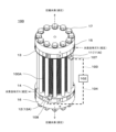
- FIG. 1 is a perspective view showing an example of an electrochemical hydrogen pump according to an embodiment.
- FIG. 2 is a diagram showing an example of a stack in the electrochemical hydrogen pump of the embodiment.
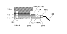
- FIG. 3A is a diagram showing an example of a terminal connection portion of a power supply plate in an electrochemical hydrogen pump of a second example of the embodiment;
- FIG. 3B is a diagram showing an example of a terminal connection portion of a power supply plate in the electrochemical hydrogen pump of Example 2 of the embodiment.
- FIG. 4 is a diagram showing an example of the result of verifying the effect of reducing the terminal resistance in the terminal connection portion of FIGS. 3A and 3B.
- the terminal configuration of the metal plate for applying the voltage of the voltage applicator to the electrochemical cell has not been sufficiently studied.
- metal plates exposed to compressed hydrogen should be constructed of conductive materials that are resistant to hydrogen embrittlement.
- the voltage of the voltage applicator may increase due to the terminal resistance at the terminals made of the conductive material with high resistivity. As a result, the efficiency of the hydrogen compression operation of the compressor can be reduced.
- the compression device of the first aspect of the present disclosure includes an electrochemical cell including an anode and a cathode with an electrolyte membrane interposed therebetween, a voltage applicator that applies a voltage between the anode and the cathode, and compressed hydrogen produced at the cathode.
- a metal plate that is exposed to and resistant to hydrogen embrittlement the metal plate including a first terminal connected to a voltage applicator, the first terminal having a second lower resistance than the first terminal; The terminal is directly connected, the second terminal is directly connected to the voltage applicator, and the first terminal is connected to the voltage applicator via the second terminal.
- the compression device of this aspect can suppress a decrease in the efficiency of the hydrogen compression operation more than before.
- a material having high resistance to hydrogen embrittlement can be selected as the material of the metal plate exposed to compressed hydrogen, and the material of the second terminal is the metal plate (first terminal) can be selected to have a lower resistivity than the material that composes the .
- the second terminal is directly connected to the voltage applicator, and the first terminal of the metal plate is connected to the voltage applicator via the second terminal, so that the first terminal of the metal plate is connected to the voltage applicator via the second terminal.
- Terminal resistance can be reduced compared to the case where the terminals are directly connected to the voltage applicator. Therefore, in the compression device of this aspect, the voltage rise of the voltage applicator caused by the terminal resistance is appropriately suppressed.
- the first terminal is connected to the voltage applicator via the second terminal
- the first terminal is electrically connected to the voltage applicator via the second terminal. means.
- the metal plate in the compression device of the first aspect, may have a channel through which compressed hydrogen flows.
- the metal plate in the compression device of the third aspect of the present disclosure, in the compression device of the first aspect or the second aspect, the metal plate may be made of SUS316 or SUS316L.
- SUS316 and SUS316L have high characteristics in terms of acid resistance and hydrogen embrittlement resistance, so it is convenient to select SUS316 or SUS316L as the material for the metal plate.
- a compression device of a fourth aspect of the present disclosure may be the compression device of any one of the first to third aspects, wherein the second terminal may be made of a material containing copper.
- the compression device of this aspect selects a copper-containing conductive material that is inexpensive and has a low resistivity as the material of the second terminal, so that compared to the case where such a conductive material is not selected, High conductivity and low cost of the second terminal are possible.
- FIG. 1 is a perspective view showing an example of an electrochemical hydrogen pump according to an embodiment.
- the electrochemical hydrogen pump 100 includes a stack 100A in which hydrogen pump units 10 (see FIG. 2) including MEAs (electrochemical cells) are stacked, and a voltage applicator .
- each of a pair of separators externally sandwiches each of the anode and cathode of the electrochemical cell.
- the anode separator in contact with the anode is a conductive plate-like member for supplying hydrogen-containing gas to the anode.
- This plate-shaped member has a gas channel through which the hydrogen-containing gas supplied to the anode flows.
- a cathode separator in contact with the cathode is a conductive plate-like member for discharging compressed hydrogen (H 2 ) from the cathode to the outside.
- This plate-like member has a connecting path 80 and a connecting path 81 (see FIG. 2) for connecting the cathode and the outside.
- the gas channel of the anode separator can be provided separately from the anode separator, it is common to form grooves for the gas channel on the surface of the anode separator, for example, in a serpentine shape.
- the above-described separators are arranged for mechanically fixing the electrochemical cells and for electrically connecting adjacent electrochemical cells in series with each other.
- Approximately 10 to 200 electrochemical cells are stacked by alternately stacking electrochemical cells and separators, and a stack 100A is formed from both sides via a pair of power supply plates 11 and 12 and a pair of insulating plates 13 and 14.
- a general laminated fastening structure is such that the end plates 15 and 16 are sandwiched between the end plates 15 and 16 and the end plates 15 and 16 are fastened with a plurality of fasteners 17 .
- a groove-like communication passage is branched from an appropriate pipe passage and connected.
- the downstream ends of the channels should be configured to connect with one end of each gas channel of the anode separator.
- Such a pipe line is called an anode gas introduction manifold, and this anode gas introduction manifold is composed of a series of through holes provided at appropriate positions in each member of the stack 100A.
- a groove-like communication path is branched from an appropriate conduit, and the downstream end of the communication path should be configured to connect with the other end of each gas channel of the anode separator.
- Such a pipe line is called an anode gas lead-out manifold, and this anode gas lead-out manifold is composed of a series of through-holes provided at appropriate positions in each member of the stack 100A.
- cathode gas lead-out manifold In order to discharge high-pressure compressed hydrogen from each cathode of the cathode separator to the outside, it is necessary to connect appropriate conduits to the communication paths 80 and 81 in each of the cathode separators.
- a conduit is called a cathode gas lead-out manifold, and this cathode gas lead-out manifold is composed of a series of through-holes provided at appropriate positions in each member of the stack 100A.
- the electrochemical hydrogen pump 100 includes a pair of end plates 15 and 16 provided on both ends in the stacking direction of the hydrogen pump unit 10, and a fastener 17 for fastening the pair of end plates 15 and 16 in the stacking direction. Prepare.
- the fastener 17 may have any configuration as long as it can fasten the plurality of hydrogen pump units 10 and the pair of end plates 15 and 16 in the stacking direction.
- the fastener 17 can include a bolt and a nut with a disc spring.
- the plurality of hydrogen pump units 10 are appropriately held in a stacked state by the fastening pressure of the fasteners 17 in the stacking direction.
- the sealing performance of the sealing members for example, the O-ring 45 and the face seal member 40 in FIG. 2 is properly exhibited between the members of the hydrogen pump unit 10, and the contact resistance between the members is reduced.
- the voltage applicator 102 is a device that applies a voltage between the anode AN and the cathode CA. Specifically, the high potential of voltage applicator 102 is applied to anode AN, and the low potential of voltage applicator 102 is applied to cathode CA. Voltage applicator 102 may have any configuration as long as it can apply a voltage between anode AN and cathode CA. For example, voltage applicator 102 may be a device that adjusts the voltage applied between anode AN and cathode CA.
- the voltage applicator 102 includes a DC/DC converter when connected to a DC power supply such as a battery, a solar battery, or a fuel cell, and an AC power supply when connected to an AC power supply such as a commercial power supply. /DC converter.
- the voltage applicator 102 adjusts the voltage applied between the anode AN and the cathode CA and the current flowing between the anode AN and the cathode CA so that the power supplied to the hydrogen pump unit 10 has a predetermined set value. It may be a power type power supply that
- FIG. 2 is a diagram showing an example of a stack in the electrochemical hydrogen pump of the embodiment.
- FIG. 2 shows, in a plan view of the electrochemical hydrogen pump 100 of FIG. A vertical section of 100A is shown.
- a plurality of hydrogen pump units 10 are stacked in the stack 100A.
- four hydrogen pump units 10 are stacked, but the number of hydrogen pump units 10 is not limited to this.
- the number of hydrogen pump units 10 can be set to an appropriate number based on operating conditions such as the amount of hydrogen to be compressed by the electrochemical hydrogen pump 100 .
- the anode separator 26 and cathode separator 27 are integrated in each hydrogen pump unit 10 .
- the bipolar plate 29 (bipolar plate) functions as the anode separator 26 of the hydrogen pump unit 10A and functions as the cathode separator 27 of the hydrogen pump unit 10B.
- the number of parts of the electrochemical hydrogen pump 100 can be reduced.
- the number of separators can be reduced, and a seal member (for example, an O-ring) provided between separators can be eliminated.
- the joining of the anode separator 26 and the cathode separator 27 may be of any configuration.
- the anode separator 26 and the cathode separator 27 can be joined by various methods such as diffusion bonding, mechanical joining such as bolting, adhesion, and welding.
- a heat medium for adjusting the temperature of the electrochemical hydrogen pump 100 flows on one or both of the joining surfaces of the cathode separator 27 and the anode separator 26.
- Channel grooves may be provided.
- anode separator 26 and the cathode separator 27 may be configured separately.
- the hydrogen pump unit 10 includes an electrolyte membrane 21, an anode AN, a cathode CA, a cathode separator 27, an anode separator 26, a face seal material 40, and an O-ring 45.
- an electrolyte membrane 21, an anode catalyst layer 24, a cathode catalyst layer 23, an anode power feeder 25, a cathode power feeder 22, an anode separator 26 and a cathode separator 27 are laminated.
- the anode AN is provided on one main surface of the electrolyte membrane 21 .
- the anode AN is an electrode including an anode catalyst layer 24 and an anode power supply 25 .
- the cathode CA is provided on the other main surface of the electrolyte membrane 21 .
- Cathode CA is an electrode including cathode catalyst layer 23 and cathode power supply 22 .
- the electrochemical hydrogen pump 100 may use a catalyst coated membrane CCM (catalyst coated membrane) in which the cathode catalyst layer 23 and the anode catalyst layer 24 are integrally bonded to the electrolyte membrane 21.
- CCM catalyst coated membrane
- the above-described anode power feeder 25 and cathode power feeder 22 are provided on the anode catalyst layer 24 and the cathode catalyst layer 23 of the catalyst layer-attached membrane CCM, respectively. Thereby, the electrolyte membrane 21 is sandwiched between the anode AN and the cathode CA.
- the electrolyte membrane 21 is a polymer membrane with proton conductivity.
- the electrolyte membrane 21 may have any configuration as long as it has proton conductivity.
- Examples of the electrolyte membrane 21 include a fluorine-based polymer electrolyte membrane and a hydrocarbon-based polymer electrolyte membrane, but are not limited to these.
- Nafion registered trademark, manufactured by DuPont
- Aciplex registered trademark, manufactured by Asahi Kasei Corporation
- the like can be used as the electrolyte membrane 21 .
- the anode catalyst layer 24 is provided so as to be in contact with one main surface of the electrolyte membrane 21 .
- the anode catalyst layer 24 contains, for example, platinum as a catalyst metal, but is not limited to this.
- the cathode catalyst layer 23 is provided so as to be in contact with the other main surface of the electrolyte membrane 21 .
- the cathode catalyst layer 23 contains, for example, platinum as a catalyst metal, but is not limited to this.
- catalyst carriers for the cathode catalyst layer 23 and the anode catalyst layer 24 include, but are not limited to, carbon particles such as carbon black and graphite, and conductive oxide particles.
- cathode catalyst layer 23 and the anode catalyst layer 24 fine particles of catalyst metal are supported on catalyst carriers in a highly dispersed manner.
- a proton-conducting ionomer component is generally added to the cathode catalyst layer 23 and anode catalyst layer 24 in order to increase the electrode reaction field.
- the cathode power supply 22 is provided on the cathode catalyst layer 23 . Also, the cathode power supply 22 is made of a porous material and has electrical conductivity and gas diffusibility. Furthermore, it is desirable that the cathode power supply 22 has elasticity so as to appropriately follow the displacement and deformation of the constituent members caused by the differential pressure between the cathode CA and the anode AN during operation of the electrochemical hydrogen pump 100 .
- a member made of carbon fiber is used as the cathode power feeder 22 .
- porous carbon fiber sheets such as carbon paper, carbon cloth, and carbon felt may be used.
- the carbon fiber sheet may not be used as the base material of the cathode power supply 22 .
- a sintered body of metal fibers made of titanium, a titanium alloy, stainless steel, or the like, or a sintered body of metal particles made of these materials may be used as the base material of the cathode power supply body 22 .
- the anode power feeder 25 is provided on the anode catalyst layer 24 .
- the anode power supply 25 is made of a porous material and has electrical conductivity and gas diffusibility. Further, the anode power supply 25 preferably has high rigidity capable of suppressing the displacement and deformation of the constituent members caused by the differential pressure between the cathode CA and the anode AN during operation of the electrochemical hydrogen pump 100 .
- examples of the base material of the anode power supply 25 include fiber sintered bodies, powder sintered bodies, expanded metals, metal meshes, punching metals, etc. made of titanium, titanium alloys, stainless steel, carbon, etc. may be used.
- the anode separator 26 is a member provided on the anode AN.
- the cathode separator 27 is a member provided on the cathode CA.
- the anode feeder 25 is in contact with a region (central portion) facing the anode AN on the anode AN side of the anode separator 26 .
- a recess is provided in the central portion of the cathode separator 27, and the cathode power supply body 22 is accommodated in this recess.
- the above anode separator 26 and cathode separator 27 may be composed of, for example, metal sheets such as titanium, stainless steel, and gold, but are not limited to this.
- the anode separator 26 and the cathode separator 27 may be made of carbon or resin with a thin film of metal such as titanium or stainless steel formed on the surface.
- the anode separator 26 and cathode separator 27 are made of stainless steel, it is desirable to select SUS316 or SUS316L as the material for the anode separator 26 and cathode separator 27 . This is because SUS316 and SUS316L have high properties among various types of stainless steel in terms of acid resistance and hydrogen embrittlement resistance.
- hydrophilicity resistance is according to Non-Patent Document 1 (Takayoshi Murakami, “Mechanism of hydrogen embrittlement and concept of hydrogen equipment strength design", published by Yokendo Co., Ltd., 2012, p213-p216).
- the tensile strength of the notched test piece in hydrogen gas and helium gas and the reduction of area of the smooth test piece are used as judgment criteria.
- a material property in which the ratio of the tensile strength in hydrogen gas to the tensile strength of helium gas flow and the ratio of the tensile strength of hydrogen gas flow to the restriction of helium gas flow are both 1 under test conditions of 69 MPa and 295 K.
- Non-Patent Document 1 describes that austenitic stainless steel, aluminum alloys, and copper alloys belong to the "non-embrittlement” group.
- Typical steel materials having such "hydrogen embrittlement resistance” are materials described in "JISG4304: Hot-rolled stainless steel plates and strips” or “JISG4305: Cold-rolled stainless steel plates and strips”.
- SUS316 or SUS316L which belongs to the above austenitic stainless steels, is applicable.
- the hydrogen pump unit 10 is formed by sandwiching the electrochemical cell between the cathode separator 27 and the anode separator 26 .
- the feeder plate 11 is in electrical contact with the cathode separator 27 positioned at one end in the stacking direction, and the feeder plate 12 is in electrical contact with the anode separator 26 positioned at the other end in the stacking direction. are in contact with
- each of the feed plate 11 and the feed plate 12 corresponds to an example of the "metal plate” of the present disclosure.
- the through holes 11H and through holes 12H are the "channels through which compressed hydrogen produced at the cathode flows" of the present disclosure. ” corresponds to an example.
- the power supply plate 11 and the power supply plate 12 must be made of a conductive material that is resistant to hydrogen embrittlement.
- the power supply plate 11 and the power supply plate 12 are desirably made of a sheet of metal such as titanium or stainless steel, carbon, or resin having a thin film of metal such as titanium or stainless steel formed on its surface.
- metal such as titanium or stainless steel, carbon, or resin having a thin film of metal such as titanium or stainless steel formed on its surface.
- SUS316 or SUS316L it is desirable to select SUS316 or SUS316L as the material for power supply plate 11 and power supply plate 12 . This is because SUS316 and SUS316L have high properties among various types of stainless steel in terms of acid resistance and hydrogen embrittlement resistance.
- the power supply plate 11 includes a first terminal 11A connected to the voltage applicator 102, and the first terminal 11A has a lower resistance than the first terminal 11A. It is directly connected to the second terminal 107 , the second terminal 107 is directly connected to the voltage applicator 102 , and the first terminal 11A is connected to the voltage applicator 102 via the second terminal 107 . That is, the terminal of the wiring 103 of the voltage applicator 102 and the second terminal 107 are in contact, and the second terminal 107 and the first terminal 11A are in contact. This electrically connects the first terminal 11A to the voltage applicator 102 via the second terminal 107 .
- the resistance R of the first terminal 11A and the second terminal 107 can be calculated by the following formula (1).
- R ⁇ L/S (1)
- the resistivity ⁇ ( ⁇ m) is a proportional constant representing the difficulty of current flow and is a numerical value specific to the material.
- ⁇ ( ⁇ m) of metal materials at room temperature are shown in Table 1 below.
- the cross-sectional area S is the thickness of the terminal (the length of the terminal in the vertical direction in FIGS. 3A and 3B) and the width of the terminal (the width of the terminal in FIGS. 3A and 3B). In terms of the cross-sectional view of the terminal, it corresponds to the product of the length of the terminal in the depth direction in the drawing.
- the length L corresponds to the length of the terminal (the length of the terminal in the lateral direction in the drawings when the cross-sectional views of the terminal in FIGS. 3A and 3B are used).
- the first terminal 11A is a part of the metal plate that constitutes the power supply plate 11, and is a protruding portion that protrudes outward in a belt shape from the side surface of the metal plate.
- the second terminal 107 is a strip-shaped and flat plate-shaped member that overlaps the first terminal 11A in surface contact.
- the connection between the terminal of the wiring 103 of the voltage applicator 102 and the second terminal 107 and the connection between the second terminal 107 and the first terminal 11A are made by connecting members (for example, bolts and nuts) not shown. The details of the second terminal 107 will be described in the first and second embodiments.
- the power supply plate 12 includes a first terminal 12A connected to the voltage applicator 102, and the first terminal 12A has a lower resistance than the first terminal 12A.
- the second terminal 108 is directly connected to the voltage applicator 102 and the first terminal 12A is connected to the voltage applicator 102 via the second terminal 108 . That is, the terminal of the wiring 104 of the voltage applicator 102 and the second terminal 108 are in contact, and the second terminal 108 and the first terminal 12A are in contact.
- the resistance R of the first terminal 12A and the second terminal 108 can be calculated by the formula (1), like the first terminal 11A and the second terminal 107.
- the first terminal 12A is a part of the metal plate that constitutes the power supply plate 12, and is a protruding portion that protrudes outward in a belt shape from the side surface of the metal plate.
- the second terminal 108 is a strip-shaped and flat plate-shaped member that overlaps the first terminal 12A in surface contact.
- the connection between the terminal of the wiring 104 of the voltage applicator 102 and the second terminal 108, and the connection between the second terminal 108 and the first terminal 12A are made by connecting members (for example, bolts and nuts) not shown. .
- the details of the second terminal 108 will be described in the first and second embodiments.
- a hydrogen system equipped with the electrochemical hydrogen pump 100.
- equipment necessary for the hydrogen compression operation of the hydrogen system is appropriately provided.
- the dew point of a mixed gas of a highly humidified hydrogen-containing gas discharged from the anode AN and a low-humidified hydrogen-containing gas supplied from an external hydrogen supply source is adjusted.
- a dew point regulator eg humidifier
- the hydrogen-containing gas of the external hydrogen supply source may be generated, for example, by a water electrolyzer.
- the hydrogen system includes, for example, a temperature detector that detects the temperature of the electrochemical hydrogen pump 100, a hydrogen reservoir that temporarily stores hydrogen discharged from the cathode CA of the electrochemical hydrogen pump 100, A pressure detector or the like for detecting the hydrogen gas pressure may be provided.
- the configuration of the electrochemical hydrogen pump 100 and various devices (not shown) in the hydrogen system are examples and are not limited to this example.
- a dead-end structure may be adopted in which all the hydrogen in the hydrogen-containing gas supplied to the anode AN through the anode gas introduction manifold is compressed at the cathode CA without providing the anode gas outlet manifold.
- the following operations may be performed, for example, by an arithmetic circuit (not shown) of the controller reading out the control program from the storage circuit of the controller. However, it is not essential that the controller perform the following operations. The operator may perform some of the operations. In the following example, the case where the operation is controlled by the controller will be described.
- a low-pressure hydrogen-containing gas is supplied to the anode AN of the electrochemical hydrogen pump 100, and the voltage of the voltage applicator 102 is applied to the first terminal 11A and the second terminal 107 and the first terminal 12A and the second terminal 108. and to the electrochemical cell.
- the hydrogen (H 2 ) generated at the cathode CA can be compressed by increasing the pressure loss in the hydrogen lead-out path using a flow rate regulator (not shown).
- a flow rate regulator for example, a back pressure valve, a regulating valve, etc. provided in the hydrogen lead-out path can be cited.
- the voltage is applied by the voltage applicator 102, whereby hydrogen in the hydrogen-containing gas supplied to the anode AN is compressed at the cathode CA.
- the electrochemical hydrogen pump 100 performs a hydrogen compression operation, and the hydrogen compressed by the cathode CA is supplied to the hydrogen consumer in a timely manner.
- Hydrogen demanders include fuel cells, hydrogen reservoirs, hydrogen infrastructure piping, and the like.
- the hydrogen compressed by the cathode CA may be temporarily stored in a hydrogen storage device, which is an example of a hydrogen consumer.
- the hydrogen stored in the hydrogen storage device may be supplied to a fuel cell, which is an example of a hydrogen consumer, at appropriate times.
- the electrochemical hydrogen pump 100 of this embodiment can suppress the decrease in efficiency of the hydrogen compression operation more than the conventional one.
- a material having high resistance to hydrogen embrittlement can be selected as the material of the power supply plate 11 exposed to compressed hydrogen, and the material of the second terminal 107 is A material having a lower resistivity than that of the plate 11 (first terminal 11A) can be selected.
- a material having high hydrogen embrittlement resistance can be selected as the material of the power supply plate 12 exposed to compressed hydrogen, and a material having a lower resistivity than that of the power supply plate 12 (the first terminal 12A) can be used as the material of the second terminal 108. can be selected.
- the second terminal 107 is directly connected to the voltage applicator 102, and the first terminal 11A of the power supply plate 11 is connected to the voltage applicator 102 via the second terminal 107.
- the terminal resistance can be reduced.
- the second terminal 108 is directly connected to the voltage applicator 102, and the first terminal 12A of the power supply plate 12 is connected to the voltage applicator 102 via the second terminal 108. Therefore, the terminal resistance can be reduced as compared with the case where the first terminal 12A of the power supply plate 12 is directly connected to the voltage applicator 102.
- the voltage rise of the voltage applicator 102 caused by the terminal resistance is appropriately suppressed.
- the electrochemical hydrogen pump 100 of this embodiment is the same as the electrochemical hydrogen pump 100 of the embodiment except for the configurations of the second terminal 107 and the second terminal 108 described below.
- the second terminal 107 and the second terminal 108 are each made of a material having a lower resistivity than the conductive material that makes up the power supply plate 11 and the power supply plate 12, respectively.
- Second terminal 107 and second terminal 108 may each be made of a material containing copper.
- each of the second terminal 107 and the second terminal 108 may be made of pure copper with a copper purity of about 99.90% or higher, or may be made of an alloy containing copper. Examples of the former pure copper include tough pitch copper and oxygen-free copper. Brass can be exemplified as the latter alloy.
- the surfaces of the second terminals 107 and 108 are preferably plated with nickel, tin, gold, or the like for the purpose of improving corrosion resistance and surface hardness.
- a nickel-plated member made of a material containing copper can be mentioned.
- the electrochemical hydrogen pump 100 of the present embodiment selects a copper-containing conductive material that is inexpensive and has a low resistivity as the material for the second terminals 107 and 108. High conductivity and low cost of the second terminal 107 and the second terminal 108 can be achieved as compared with the case where no conductive material is selected.
- the electrochemical hydrogen pump 100 of this embodiment may be the same as the electrochemical hydrogen pump 100 of the embodiment except for the features described above.
- the electrochemical hydrogen pump 100 of this embodiment is the same as the electrochemical hydrogen pump 100 of the embodiment except for the configurations of the second terminal 107 and the second terminal 108 described below.
- FIG. 3A and 3B are diagrams showing an example of the terminal connection portion of the power supply plate in the electrochemical hydrogen pump of the second example of the embodiment.
- FIG. 3A shows a cross section of a terminal connection portion of power supply plate 11
- FIG. 3B shows a cross section of a terminal connection portion of power supply plate 12. As shown in FIG.
- the second terminal 107 includes a first bus bar 107A superimposed so as to be in surface contact with one main surface of the first terminal 11A, and a first bus bar 107A so as to be in surface contact with the other main surface of the first terminal 11A. and a second bus bar 107B (additional bus bar) superimposed on.
- first bus bar 107A superimposed so as to be in surface contact with one main surface of the first terminal 11A
- first bus bar 107A so as to be in surface contact with the other main surface of the first terminal 11A.
- a second bus bar 107B additional bus bar
- first bus bar 107A, the first terminal 11A, and the second bus bar 107B are fixed by appropriate connecting members (for example, bolts and nuts) so that they constitute the laminated portion 200. That is, both main surfaces of first terminal 11A are in surface contact with respective main surfaces of first busbar 107A and second busbar 107B, so that first terminal 11A is connected to first busbar 107A and second busbar 107B. sandwiched by.
- first busbar 107A and the first terminal 11A and the contact resistance between the first terminal 11A and the second bus bar 107B are reduced. resistance can be reduced.
- first bus bar 107A extends outside the laminated portion 200, and the main surface of the extended portion 300 of the first bus bar 107A is in surface contact with the terminal 105 of the wiring 103.
- the first bus bar 107A and the terminal 105 of the wiring 103 are fixed by appropriate connecting members (for example, bolts and nuts) so that they are stacked. When a desired fastening force is applied to each member by bolts and nuts, the contact resistance between first bus bar 107A and terminal 105 of wiring 103 can be reduced.
- the first bus bar 107A, the first terminal 11A, and the second bus bar 107B are arranged as compared with the case where the bus bar is arranged only on one main surface of the first terminal 11A. Since the volume of the laminated portion 200 on which the is superimposed increases, the volume resistance of the laminated portion 200 is improved.
- the thinner the metal plate is the greater the resistance of the first terminal 11A protruding outward from the side surface of the metal plate becomes.
- the electrochemical hydrogen pump 100 of this embodiment by increasing the volume of the laminated portion 200, an increase in the resistance of the first terminal 11A is appropriately suppressed.
- the configuration of the terminal connection portion of the power supply plate 12 can be easily understood from the above content, so the description is omitted.
- the configuration of the second terminal 108 in FIG. 3B is an example, and is not limited to this example.
- second terminal 108 may not include second bus bar 108B.
- FIG. 4 is a diagram showing an example of the result of verifying the effect of reducing the terminal resistance in the terminal connection portion of FIGS. 3A and 3B.
- the horizontal axis represents the elapsed time from the start of the hydrogen compression operation of the electrochemical hydrogen pump 100 and the vertical axis represents the voltage of the voltage applicator 102 .
- a gold-plated metal plate made of SUS316L was used for each of the members forming the power supply plate 11 and the first terminals 11A, and the members forming the power supply plate 12 and the first terminals 12A.
- the members constituting second terminal 107 and second terminal 108 are nickel-plated first bus bar 107A and second bus bar 107B made of pure copper, and nickel-plated first bus bar 108A and second bus bar 108A made of pure copper, respectively.
- Two busbars 108B were used respectively.
- the voltage of the voltage applicator 102 when the second terminal 107 and the second terminal 108 are used is indicated by a dotted line.
- 102 voltage is shown as a solid line. That is, in the latter case, in the terminal connection portion of FIGS. 3A and 3B, the second terminal 107 and the second terminal 108 are not provided, and the terminal 105 of the wiring 103 and the terminal 106 of the wiring 104 are respectively connected to the first terminal 11A. and the first terminals 12A.
- the second terminal 107 and the second terminal 108 are used as shown by the dotted line in FIG. It has been found that the voltage of the voltage applicator 102 is thereby reduced. As a result, the effect of reducing the terminal resistance at the terminal connection portion in FIGS. 3A and 3B could be verified by the second terminal 107 and the second terminal 108 .
- the electrochemical hydrogen pump 100 of this embodiment may be the same as the electrochemical hydrogen pump 100 of the embodiment or the first embodiment of the embodiment, except for the features described above.
- the electrochemical hydrogen pump 100 of this modified example is the same as the electrochemical hydrogen pump 100 of the embodiment except for the configurations of the power supply plate 11 and the power supply plate 12 described below.
- the cathode separator 27 and the power supply plate 11 are configured separately, and the anode separator 26 and the power supply plate 12 are configured separately.
- the electrochemical hydrogen pump 100 of this modification includes a metal member in which the cathode separator 27 and the power supply plate 11 are integrated. Further, the electrochemical hydrogen pump 100 of this modified example includes a metal member in which the anode separator 26 and the power supply plate 12 are integrated.
- the cathode separator 27 and the power supply plate 11 may be integrated by diffusion bonding or the like.
- the anode separator 26 and the power supply plate 12 may be integrated by diffusion bonding or the like.
- the metal member corresponds to an example of the "metal plate” of the present disclosure.
- the through-holes forming the cathode lead-out manifold in the metal member correspond to an example of the "flow path through which the compressed hydrogen generated at the cathode flows" of the present disclosure.
- the communication path 80 and the communication path 81 in the metal member functioning as the cathode separator correspond to an example of the "channel through which the compressed hydrogen generated at the cathode flows" of the present disclosure.
- the electrochemical hydrogen pump 100 of this modified example may be the same as the electrochemical hydrogen pump 100 of either the embodiment or the first to second examples of the embodiment, except for the features described above.
- One aspect of the present disclosure can be used for a compression device that can suppress the reduction in efficiency of hydrogen compression operation more than before.
Landscapes
- Chemical & Material Sciences (AREA)
- Engineering & Computer Science (AREA)
- Organic Chemistry (AREA)
- Chemical Kinetics & Catalysis (AREA)
- Electrochemistry (AREA)
- Materials Engineering (AREA)
- Metallurgy (AREA)
- Inorganic Chemistry (AREA)
- Sustainable Energy (AREA)
- General Chemical & Material Sciences (AREA)
- Life Sciences & Earth Sciences (AREA)
- Sustainable Development (AREA)
- Manufacturing & Machinery (AREA)
- Combustion & Propulsion (AREA)
- Electrolytic Production Of Non-Metals, Compounds, Apparatuses Therefor (AREA)
- Hydrogen, Water And Hydrids (AREA)
Priority Applications (4)
| Application Number | Priority Date | Filing Date | Title |
|---|---|---|---|
| EP22901016.0A EP4442863A4 (en) | 2021-11-30 | 2022-11-02 | COMPRESSION DEVICE |
| JP2023564825A JP7526944B2 (ja) | 2021-11-30 | 2022-11-02 | 圧縮装置 |
| CN202280078466.6A CN118318068A (zh) | 2021-11-30 | 2022-11-02 | 压缩装置 |
| US18/661,344 US20240301570A1 (en) | 2021-11-30 | 2024-05-10 | Compression device |
Applications Claiming Priority (2)
| Application Number | Priority Date | Filing Date | Title |
|---|---|---|---|
| JP2021193865 | 2021-11-30 | ||
| JP2021-193865 | 2021-11-30 |
Related Child Applications (1)
| Application Number | Title | Priority Date | Filing Date |
|---|---|---|---|
| US18/661,344 Continuation US20240301570A1 (en) | 2021-11-30 | 2024-05-10 | Compression device |
Publications (1)
| Publication Number | Publication Date |
|---|---|
| WO2023100583A1 true WO2023100583A1 (ja) | 2023-06-08 |
Family
ID=86611956
Family Applications (1)
| Application Number | Title | Priority Date | Filing Date |
|---|---|---|---|
| PCT/JP2022/040945 Ceased WO2023100583A1 (ja) | 2021-11-30 | 2022-11-02 | 圧縮装置 |
Country Status (5)
| Country | Link |
|---|---|
| US (1) | US20240301570A1 (https=) |
| EP (1) | EP4442863A4 (https=) |
| JP (1) | JP7526944B2 (https=) |
| CN (1) | CN118318068A (https=) |
| WO (1) | WO2023100583A1 (https=) |
Cited By (1)
| Publication number | Priority date | Publication date | Assignee | Title |
|---|---|---|---|---|
| DE102023213032A1 (de) | 2023-12-20 | 2025-06-26 | Robert Bosch Gesellschaft mit beschränkter Haftung | Elektrolysezelle und Verfahren zur Herstellung einer Elektrolysezelle |
Citations (5)
| Publication number | Priority date | Publication date | Assignee | Title |
|---|---|---|---|---|
| JPS52142286A (en) * | 1977-05-30 | 1977-11-28 | Sanyo Electric Co Ltd | Connection of copper made lead wire and stainless steel made conductor |
| JP6129809B2 (ja) | 2014-11-06 | 2017-05-17 | 本田技研工業株式会社 | 差圧式高圧水電解装置 |
| JP2017520899A (ja) * | 2014-04-29 | 2017-07-27 | サン−ゴバン グラス フランスSaint−Gobain Glass France | 基板上の導電性構造を接続するための電気接続エレメント |
| JP2017218668A (ja) * | 2016-06-06 | 2017-12-14 | パナソニックIpマネジメント株式会社 | 電気化学式水素ポンプ |
| JP6928922B1 (ja) | 2020-01-08 | 2021-09-01 | パナソニックIpマネジメント株式会社 | 圧縮装置 |
Family Cites Families (5)
| Publication number | Priority date | Publication date | Assignee | Title |
|---|---|---|---|---|
| US4923582A (en) * | 1982-12-27 | 1990-05-08 | Eltech Systems Corporation | Monopolar, bipolar and/or hybrid memberane cell |
| BRPI0921570A2 (pt) * | 2008-11-25 | 2019-09-24 | Nissan Motor | membro condutor de eletricidade e célula de combustível de eletrólito de polímero utilizando o mesmo |
| KR20180023687A (ko) * | 2016-08-26 | 2018-03-07 | (주)엘켐텍 | 정류기 일체형 수전해 셀 및 수전해 스택 |
| KR20190040678A (ko) * | 2017-10-11 | 2019-04-19 | (주)엘켐텍 | 부식방지층을 갖는 메탈폼 압력매트 및 이를 구비한 전기화학 셀과 전기화학용 스택 |
| US12486582B2 (en) * | 2020-04-23 | 2025-12-02 | Hyter S.r.l. | Apparatus for generating hydrogen and oxygen through alkaline electrolysis, and corresponding process |
-
2022
- 2022-11-02 CN CN202280078466.6A patent/CN118318068A/zh active Pending
- 2022-11-02 JP JP2023564825A patent/JP7526944B2/ja active Active
- 2022-11-02 WO PCT/JP2022/040945 patent/WO2023100583A1/ja not_active Ceased
- 2022-11-02 EP EP22901016.0A patent/EP4442863A4/en active Pending
-
2024
- 2024-05-10 US US18/661,344 patent/US20240301570A1/en active Pending
Patent Citations (5)
| Publication number | Priority date | Publication date | Assignee | Title |
|---|---|---|---|---|
| JPS52142286A (en) * | 1977-05-30 | 1977-11-28 | Sanyo Electric Co Ltd | Connection of copper made lead wire and stainless steel made conductor |
| JP2017520899A (ja) * | 2014-04-29 | 2017-07-27 | サン−ゴバン グラス フランスSaint−Gobain Glass France | 基板上の導電性構造を接続するための電気接続エレメント |
| JP6129809B2 (ja) | 2014-11-06 | 2017-05-17 | 本田技研工業株式会社 | 差圧式高圧水電解装置 |
| JP2017218668A (ja) * | 2016-06-06 | 2017-12-14 | パナソニックIpマネジメント株式会社 | 電気化学式水素ポンプ |
| JP6928922B1 (ja) | 2020-01-08 | 2021-09-01 | パナソニックIpマネジメント株式会社 | 圧縮装置 |
Non-Patent Citations (1)
| Title |
|---|
| See also references of EP4442863A4 |
Cited By (1)
| Publication number | Priority date | Publication date | Assignee | Title |
|---|---|---|---|---|
| DE102023213032A1 (de) | 2023-12-20 | 2025-06-26 | Robert Bosch Gesellschaft mit beschränkter Haftung | Elektrolysezelle und Verfahren zur Herstellung einer Elektrolysezelle |
Also Published As
| Publication number | Publication date |
|---|---|
| EP4442863A4 (en) | 2025-03-19 |
| US20240301570A1 (en) | 2024-09-12 |
| JP7526944B2 (ja) | 2024-08-02 |
| JPWO2023100583A1 (https=) | 2023-06-08 |
| CN118318068A (zh) | 2024-07-09 |
| EP4442863A1 (en) | 2024-10-09 |
Similar Documents
| Publication | Publication Date | Title |
|---|---|---|
| JP7426597B2 (ja) | 電気化学式水素ポンプ | |
| JP7209221B2 (ja) | 電気化学式水素ポンプ | |
| JP7336703B2 (ja) | 電気化学式水素ポンプ | |
| JP6928922B1 (ja) | 圧縮装置 | |
| JP6928921B1 (ja) | 圧縮装置 | |
| CN110670088A (zh) | 电化学式氢气泵 | |
| US20240060190A1 (en) | Electrochemical cell for hydrogen pump and compression apparatus | |
| JP6979634B1 (ja) | 圧縮装置 | |
| US20240301570A1 (en) | Compression device | |
| JP6998556B1 (ja) | 電気化学式水素ポンプ用アノードセパレータおよび電気化学式水素ポンプ | |
| JPWO2021111774A1 (ja) | 電気化学デバイス | |
| US12331416B2 (en) | Compression apparatus for hydrogen-containing gas utilizing an anode separator arrangement | |
| JP6979636B1 (ja) | 圧縮装置 | |
| JP7281646B1 (ja) | 圧縮装置 | |
| JP6895626B1 (ja) | 電気化学デバイス | |
| WO2022064817A1 (ja) | 電気化学式水素ポンプ用アノードセパレータおよび電気化学式水素ポンプ |
Legal Events
| Date | Code | Title | Description |
|---|---|---|---|
| 121 | Ep: the epo has been informed by wipo that ep was designated in this application |
Ref document number: 22901016 Country of ref document: EP Kind code of ref document: A1 |
|
| DPE1 | Request for preliminary examination filed after expiration of 19th month from priority date (pct application filed from 20040101) | ||
| WWE | Wipo information: entry into national phase |
Ref document number: 2023564825 Country of ref document: JP |
|
| WWE | Wipo information: entry into national phase |
Ref document number: 202280078466.6 Country of ref document: CN |
|
| NENP | Non-entry into the national phase |
Ref country code: DE |
|
| ENP | Entry into the national phase |
Ref document number: 2022901016 Country of ref document: EP Effective date: 20240701 |