WO2023100522A1 - 摺動式等速自在継手 - Google Patents
摺動式等速自在継手 Download PDFInfo
- Publication number
- WO2023100522A1 WO2023100522A1 PCT/JP2022/039337 JP2022039337W WO2023100522A1 WO 2023100522 A1 WO2023100522 A1 WO 2023100522A1 JP 2022039337 W JP2022039337 W JP 2022039337W WO 2023100522 A1 WO2023100522 A1 WO 2023100522A1
- Authority
- WO
- WIPO (PCT)
- Prior art keywords
- peripheral surface
- spherical
- joint member
- cage
- dci
- Prior art date
- Legal status (The legal status is an assumption and is not a legal conclusion. Google has not performed a legal analysis and makes no representation as to the accuracy of the status listed.)
- Ceased
Links
Images







Classifications
-
- F—MECHANICAL ENGINEERING; LIGHTING; HEATING; WEAPONS; BLASTING
- F16—ENGINEERING ELEMENTS AND UNITS; GENERAL MEASURES FOR PRODUCING AND MAINTAINING EFFECTIVE FUNCTIONING OF MACHINES OR INSTALLATIONS; THERMAL INSULATION IN GENERAL
- F16D—COUPLINGS FOR TRANSMITTING ROTATION; CLUTCHES; BRAKES
- F16D3/00—Yielding couplings, i.e. with means permitting movement between the connected parts during the drive
- F16D3/16—Universal joints in which flexibility is produced by means of pivots or sliding or rolling connecting parts
- F16D3/20—Universal joints in which flexibility is produced by means of pivots or sliding or rolling connecting parts one coupling part entering a sleeve of the other coupling part and connected thereto by sliding or rolling members
- F16D3/22—Universal joints in which flexibility is produced by means of pivots or sliding or rolling connecting parts one coupling part entering a sleeve of the other coupling part and connected thereto by sliding or rolling members the rolling members being balls, rollers, or the like, guided in grooves or sockets in both coupling parts
- F16D3/223—Universal joints in which flexibility is produced by means of pivots or sliding or rolling connecting parts one coupling part entering a sleeve of the other coupling part and connected thereto by sliding or rolling members the rolling members being balls, rollers, or the like, guided in grooves or sockets in both coupling parts the rolling members being guided in grooves in both coupling parts
- F16D3/224—Universal joints in which flexibility is produced by means of pivots or sliding or rolling connecting parts one coupling part entering a sleeve of the other coupling part and connected thereto by sliding or rolling members the rolling members being balls, rollers, or the like, guided in grooves or sockets in both coupling parts the rolling members being guided in grooves in both coupling parts the groove centre-lines in each coupling part lying on a sphere
- F16D3/2245—Universal joints in which flexibility is produced by means of pivots or sliding or rolling connecting parts one coupling part entering a sleeve of the other coupling part and connected thereto by sliding or rolling members the rolling members being balls, rollers, or the like, guided in grooves or sockets in both coupling parts the rolling members being guided in grooves in both coupling parts the groove centre-lines in each coupling part lying on a sphere where the groove centres are offset from the joint centre
-
- F—MECHANICAL ENGINEERING; LIGHTING; HEATING; WEAPONS; BLASTING
- F16—ENGINEERING ELEMENTS AND UNITS; GENERAL MEASURES FOR PRODUCING AND MAINTAINING EFFECTIVE FUNCTIONING OF MACHINES OR INSTALLATIONS; THERMAL INSULATION IN GENERAL
- F16D—COUPLINGS FOR TRANSMITTING ROTATION; CLUTCHES; BRAKES
- F16D3/00—Yielding couplings, i.e. with means permitting movement between the connected parts during the drive
- F16D3/16—Universal joints in which flexibility is produced by means of pivots or sliding or rolling connecting parts
- F16D3/20—Universal joints in which flexibility is produced by means of pivots or sliding or rolling connecting parts one coupling part entering a sleeve of the other coupling part and connected thereto by sliding or rolling members
- F16D3/22—Universal joints in which flexibility is produced by means of pivots or sliding or rolling connecting parts one coupling part entering a sleeve of the other coupling part and connected thereto by sliding or rolling members the rolling members being balls, rollers, or the like, guided in grooves or sockets in both coupling parts
- F16D3/223—Universal joints in which flexibility is produced by means of pivots or sliding or rolling connecting parts one coupling part entering a sleeve of the other coupling part and connected thereto by sliding or rolling members the rolling members being balls, rollers, or the like, guided in grooves or sockets in both coupling parts the rolling members being guided in grooves in both coupling parts
- F16D3/226—Universal joints in which flexibility is produced by means of pivots or sliding or rolling connecting parts one coupling part entering a sleeve of the other coupling part and connected thereto by sliding or rolling members the rolling members being balls, rollers, or the like, guided in grooves or sockets in both coupling parts the rolling members being guided in grooves in both coupling parts the groove centre-lines in each coupling part lying on a cylinder co-axial with the respective coupling part
- F16D3/227—Universal joints in which flexibility is produced by means of pivots or sliding or rolling connecting parts one coupling part entering a sleeve of the other coupling part and connected thereto by sliding or rolling members the rolling members being balls, rollers, or the like, guided in grooves or sockets in both coupling parts the rolling members being guided in grooves in both coupling parts the groove centre-lines in each coupling part lying on a cylinder co-axial with the respective coupling part the joints being telescopic
Definitions
- the present invention relates to power transmission systems for automobiles and various industrial machines, such as sliding constant velocity universal joints used for drive shafts and propeller shafts of automobiles.
- Constant velocity universal joints applied to drive shafts can be broadly classified into fixed constant velocity universal joints that allow only angular displacement between two axes, and sliding constant velocity universal joints that allow angular displacement and axial displacement. There are joints, and various types are selected according to the usage conditions and applications.
- the drive shaft of an automobile usually uses a fixed constant velocity universal joint on the drive wheel side (also called the outboard side), and uses a sliding constant velocity universal joint on the differential side (also called the inboard side). It is configured by connecting these two constant velocity universal joints with an intermediate shaft.
- Double offset type constant velocity universal joints (DOJ) and tripod type constant velocity universal joints (TJ) are typical sliding type constant velocity universal joints.
- DOJ type sliding constant velocity universal joint is widely used because of its low manufacturing cost and little backlash in the rotational direction inside the joint. Further, as the DOJ type sliding constant velocity universal joint, those having 6 or 8 balls are known. DOJ is described, and Patent Literature 2 describes a DOJ with a maximum operating angle of 30° or more, which is intended to increase the operating angle and to be lighter and more compact.
- the DOJ type sliding constant velocity universal joint has the weak point that it is slightly inferior in durability to the TJ type sliding constant velocity universal joint.
- the reason for this is that the constituent parts of the TJ type sliding constant velocity universal joint are mainly in rolling contact, whereas the constituent parts of the DOJ type sliding constant velocity universal joint are mainly in sliding contact. , the decrease in durability due to heat generation.
- the object of the present invention is to provide a sliding constant velocity universal joint of the DOJ type that has improved operability, low heat generation, and improved durability.
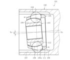
- FIG. 9 is a vertical cross-sectional view showing a conventional DOJ-type sliding constant velocity universal joint focused on in the development process.
- This sliding constant velocity universal joint 101 mainly comprises an outer joint member 102 , an inner joint member 103 , torque transmission balls 104 and a cage 105 .
- Six track grooves 107 are formed on the cylindrical inner peripheral surface 106 of the outer joint member 102 at equal intervals in the circumferential direction and linearly along the axial direction.
- track grooves 109 facing the track grooves 107 of the outer joint member 102 are formed at regular intervals in the circumferential direction and linearly along the axial direction.
- a plurality of torque transmission balls (hereinafter simply referred to as balls) 104 are incorporated between the track grooves 107 of the outer joint member 102 and the track grooves 109 of the inner joint member 103, and the balls 104 are accommodated in the pockets 105a of the cage 105. ing.
- the cage 105 has a spherical outer peripheral surface 111 and a spherical inner peripheral surface 112.
- the spherical outer peripheral surface 111 is fitted and guided in contact with the cylindrical inner peripheral surface 106 of the outer joint member 102, and the spherical inner peripheral surface 112 is inside. It is engaged with the spherical outer peripheral surface 108 of the joint member 103 and is guided in contact therewith.
- the spherical outer peripheral surface 108 of the inner joint member 103 and the spherical inner peripheral surface 112 of the cage 105 have a center of curvature at O1 that is offset by F in the axial direction from the joint center O, and the radius of curvature RCI of the spherical inner peripheral surface 112 and the spherical inner peripheral surface 112 are the same.
- the radius of curvature RI of the outer peripheral surface 108 is set to be substantially the same, and the spherical clearance between the spherical inner peripheral surface 112 and the spherical outer peripheral surface 108 is set to approximately 0.010 to 0.200 mm.
- the inner diameter dimension DCI of the spherical inner peripheral surface 112 is twice the radius of curvature RCI, and the outer diameter dimension DI of the spherical outer peripheral surface 108 is twice the radius of curvature RI.
- a spherical outer peripheral surface 111 of the cage 105 is formed with a radius of curvature RCO having a center of curvature at O2 which is offset by F from the joint center O in the axial direction opposite to O1.
- the ball 104 and the pocket 105a of the cage 105 are set with a clearance or interference depending on vehicle characteristics.
- the pocket width Lw shown in FIG. 9 is formed slightly larger than the ball diameter D BALL (Lw>D BALL ), and in the case of setting the interference, the pocket width Lw is slightly smaller than the ball diameter D BALL . is formed (Lw ⁇ D BALL ).
- FIG. 10 shows the state inside the joint as a longitudinal section.
- the normal joint angle refers to the operating angle of the front drive shaft when the steering wheel is steered straight ahead in a car with one passenger on a horizontal and flat road surface.
- the normal use angle is usually selected and determined between 2° and 15° according to design conditions for each vehicle type. As shown in FIG.
- the axial relative distance due to the spherical clearance between the inner joint member 103 and the cage 105 is smaller at the end positions than at the center position of the spherical inner peripheral surface 112 of the cage 105. becomes (L1 ⁇ L2). Since the axial clearance due to the spherical clearance between the inner joint member 103 and the cage 105 has a relationship of L1 ⁇ L2, as shown in FIG. , the contact at the ends becomes stronger. As a result, it was found that wear and heat generation increased, which affected the durability.
- the inventors conceived of bringing the spherical inner peripheral surface of the cage and the spherical outer peripheral surface of the inner joint member into surface contact on the end side of the spherical inner peripheral surface of the cage. reached.
- the present invention provides an outer joint member having a plurality of linear track grooves formed along the axial direction on a cylindrical inner peripheral surface; an inner joint member in which a plurality of linear track grooves facing the plurality of linear track grooves are formed along the axial direction; a plurality of linear track grooves in the outer joint member and the inner joint member; A plurality of torque transmission balls incorporated between a plurality of linear track grooves, the torque transmission balls being accommodated in pockets, the cylindrical inner peripheral surface of the outer joint member and the spherical outer peripheral surface of the inner joint member.
- the center of curvature of the spherical outer peripheral surface and the center of curvature of the spherical inner peripheral surface of the cage are axially opposite to the center of the joint.
- the center of curvature of the spherical inner peripheral surface of the cage and the center of curvature of the spherical outer peripheral surface of the inner joint member are the same, and the radius of curvature of the spherical inner peripheral surface of the cage is the same.
- a spherical gap is formed between the spherical inner peripheral surface of the cage and the spherical outer peripheral surface of the inner joint member so as to enable contact and guidance by making the radius of curvature of the spherical outer peripheral surface of the inner joint member approximately the same.
- the sliding constant velocity universal joint takes an operating angle
- the spherical inner peripheral surface of the cage and the spherical outer peripheral surface of the inner joint member are aligned with each other on the end side of the spherical inner peripheral surface of the cage. characterized by contact.
- the spherical outer peripheral surface of the inner joint member is provided with a minute difference between the outer diameter dimension DI at the center in the axial direction and the outer diameter dimension DI′ at both ends in the axial direction.
- DI' and a small difference is provided between the inner diameter dimension DCI at the center in the axial direction of the spherical inner peripheral surface of the cage and the inner diameter dimension DCI' at the diagonal line at both ends in the axial direction to satisfy DCI ⁇ DCI'.
- the outer diameter dimension DI at the axial center of the spherical outer peripheral surface of the inner joint member means the outer diameter dimension DI in the direction perpendicular to the axis of the inner joint member passing through the axial center of the inner joint member.
- the diagonal outer diameter dimension DI′ of both ends in the axial direction of the spherical outer peripheral surface of the inner joint member means the outer diameter dimension DI′ that diagonally crosses both axial ends of the spherical outer peripheral surface of the inner joint member. do.
- the inner diameter dimension DCI at the axial center of the spherical inner peripheral surface of the cage means the inner diameter dimension DCI in the direction orthogonal to the axis of the cage passing through the axial center of the spherical inner peripheral surface of the cage.
- the diagonal inner diameter dimension DCI′ at both axial ends of the cage means the inner diameter dimension DCI′ diagonally crossing both axial end portions of the spherical inner peripheral surface of the cage.
- the position of the spherical inner peripheral surface of the cage, which diagonally crosses both ends in the axial direction, is in a range with a margin (for example, about 1 to 2 mm) from the chamfering of the ends.
- the position diagonally crossing both axial ends of the spherical outer peripheral surface of the inner joint member is axially equivalent to the position diagonally crossing both axial ends of the spherical inner peripheral surface of the cage.
- the spherical outer peripheral surface of the inner joint member is defined by the outer diameter dimension (DI) at the center in the axial direction, the outer diameter dimension DI' at both ends in the axial direction, and the spherical inner peripheral surface of the cage as the axis.
- the inner diameter dimension DCI at the direction center and the diagonal inner diameter dimension DCI′ at both ends in the axial direction are respectively used in the above meaning.
- the difference between DI and DI' is 0 ⁇ (DI-DI') ⁇ 0.020 mm, and the difference between DCI and DCI' is 0 ⁇ (DCI'-DCI) ⁇ 0.
- the spherical outer peripheral surface of the inner joint member is provided with a minute difference between the outer diameter dimension DI at the center in the axial direction and the outer diameter dimension DI' at the diagonal line at both ends in the axial direction so that DI>DI'. is desirable.
- the spherical outer peripheral surface of the inner joint member and the spherical inner peripheral surface of the cage only the spherical outer peripheral surface of the inner joint member is provided with the above minute difference.
- the spherical outer peripheral surface of the member is in surface contact with the spherical inner peripheral surface of the cage on the end side.
- DCI ⁇ DCI' by providing a small difference between the inner diameter dimension DCI at the center in the axial direction and the diagonal inner diameter dimension DCI' at both ends in the axial direction of the spherical inner peripheral surface of the cage.
- the spherical outer peripheral surface of the inner joint member and the spherical inner peripheral surface of the cage only the spherical inner peripheral surface of the cage is provided with the above minute difference. is in surface contact with the spherical inner peripheral surface of the cage on the end side of the spherical inner peripheral surface of the cage.
- the spherical inner surface of the cage is Since minute differences in the above dimensional range are provided only on the peripheral surface, processing is easy and simple.
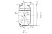
- FIG. 3 is a vertical cross-sectional view of the sliding constant velocity universal joint according to the first embodiment of the present invention, taken along line BNB of FIG. 2;
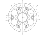
- FIG. 2 is a cross-sectional view of the sliding constant velocity universal joint according to the first embodiment of the present invention, taken along line AA of FIG. 1;
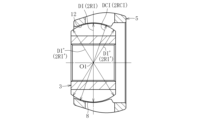
- FIG. 4 is a vertical sectional view showing the state inside the joint when the sliding constant velocity universal joint of the present embodiment takes a normal angle. It is a longitudinal cross-sectional view showing details of an inner joint member and a cage of the sliding constant velocity universal joint of the present embodiment.
- FIG. 3 is a vertical cross-sectional view of the sliding constant velocity universal joint according to the first embodiment of the present invention, taken along line BNB of FIG. 2;
- FIG. 2 is a cross-sectional view of the sliding constant velocity universal joint according to the first embodiment of the present invention, taken along line AA of FIG. 1;
- FIG. 4 is a vertical sectional view showing the state inside the joint when the sliding constant velocity universal joint of
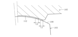
- FIG. 4 is a partial vertical cross-sectional view enlarging a gap between the spherical inner peripheral surface of the cage and the spherical outer peripheral surface of the inner joint member on the end side of the spherical inner peripheral surface of the cage of FIG. 3 ;
- FIG. 6 is a partial longitudinal sectional view showing a state in which the spherical inner peripheral surface of the inner joint member is in surface contact with the end portion side of the spherical inner peripheral surface of the cage of FIG. 5 ;
- FIG. 6 is a longitudinal sectional view showing a cage and an inner joint member in a sliding constant velocity universal joint according to a second embodiment of the present invention;
- FIG. 10 is a vertical cross-sectional view showing a cage and an inner joint member in a sliding constant velocity universal joint according to a third embodiment of the present invention
- FIG. 2 is a vertical cross-sectional view showing findings in the development process leading to the present invention
- FIG. 2 is a vertical cross-sectional view showing findings in the development process leading to the present invention
- FIG. 2 is a vertical cross-sectional view showing findings in the development process leading to the present invention
- FIG. 2 is a vertical cross-sectional view showing findings in the development process leading to the present invention
- FIG. 2 is a vertical cross-sectional view showing findings in the development process leading to the present invention
- FIG. 1 is a longitudinal sectional view of a sliding constant velocity universal joint according to a first embodiment of the present invention, taken along the line BNB of FIG. 2.
- FIG. FIG. 2 is a cross-sectional view of the sliding constant velocity universal joint according to the first embodiment of the present invention, taken along line AA of FIG. 1.
- FIG. 3 is a longitudinal sectional view showing the state inside the sliding constant velocity universal joint of the present embodiment when the joint is at a normal angle.
- FIG. 4 is a longitudinal sectional view showing details of an inner joint member and a cage of the sliding constant velocity universal joint of this embodiment.
- FIG. 5 is a partial longitudinal sectional view enlarging the gap between the spherical inner peripheral surface of the cage and the spherical outer peripheral surface of the inner joint member on the end side of the spherical inner peripheral surface of the cage of
- FIG. 6 is a partial longitudinal sectional view showing a state in which the spherical inner peripheral surface of the inner joint member is in surface contact with the end portion side of the spherical inner peripheral surface of the cage of FIG. 5.
- FIG. 1 and 3 to 6 exaggerately illustrate the clearance between the spherical inner peripheral surface of the cage and the spherical outer peripheral surface of the inner joint member for easy understanding.
- the sliding constant velocity universal joint 1 is a so-called double-offset sliding constant velocity universal joint (also abbreviated as DOJ).
- the inner joint member 3, the torque transmission balls 4 and the cage 5 are the main components.
- Six track grooves 7 are formed in the cylindrical inner peripheral surface 6 of the outer joint member 2 at equal intervals in the circumferential direction and linearly along the axial direction.
- Track grooves 9 facing the track grooves 7 of the outer joint member 2 are formed on the spherical outer peripheral surface 8 of the inner joint member 3 at regular intervals in the circumferential direction and linearly along the axial direction.
- Balls 4 are housed in pockets 5 a of cage 5 .
- the cage 5 has a spherical outer peripheral surface 11 and a spherical inner peripheral surface 12.
- the spherical outer peripheral surface 11 is fitted and guided in contact with the cylindrical inner peripheral surface 6 of the outer joint member 2, and the spherical inner peripheral surface 12 is inside. It is engaged with and guided by the spherical outer peripheral surface 8 of the joint member 3 .
- a spherical outer peripheral surface 11 of the cage 5 is formed with a radius of curvature RCO with a center of curvature O2.
- the center of curvature of the spherical inner peripheral surface 12 of the cage 5 and the center of curvature of the spherical outer peripheral surface 8 of the inner joint member 3 are both O1. Details of the radius of curvature will be described later.
- the centers of curvature O1, O2 are located on the axis N and are axially offset from the joint center O by an equal distance F.
- a retaining ring groove is provided at the opening side end of the outer joint member 2, and a retaining ring is attached to the retaining ring groove to form the inner joint member 3, the balls 4, and the cage 5 shown in FIG.
- the assembly is prevented from slipping out of the opening side end of the outer joint member 2.
- - ⁇ A boot mounting groove is provided on the outer circumference of the opening-side end of the outer joint member 2 .
- a stem portion is integrally formed on the side opposite to the opening of the outer joint member 2 and connected to the differential.
- a spline (including serrations, the same shall apply hereinafter) 14 is formed in the connecting hole 13 of the inner joint member 3 , and the shaft end of the intermediate shaft is spline-fitted. is axially fixed by
- FIG. 1 Six pockets 5a are provided at equal intervals in the circumferential direction at the axial center of the cage 5 indicated by line AA in FIG. 1, and columns 5b (see FIG. 2) are provided between adjacent pockets 5a. .
- a notch 5c for incorporating the inner joint member 3 is provided on the inner periphery of the large-diameter end of the cage 5 .
- the ball 4 and the pocket 5a of the cage 5 are set with a clearance or interference depending on vehicle characteristics.
- the pocket width Lw shown in FIG. 1 is formed slightly larger than the ball diameter D BALL (Lw>D BALL )
- the pocket width Lw is slightly smaller than the ball diameter D BALL . is formed (Lw ⁇ D BALL ).
- FIG. 4 is a detailed vertical cross-sectional view of the inner joint member 3 and the cage 5 of the sliding constant velocity universal joint 1 of the present embodiment
- the spherical inner peripheral surface 12 of the cage 5 extends toward the center in the axial direction. is formed with an inner diameter dimension DCI, and both ends in the axial direction are formed with a diagonal inner diameter dimension DCI'.
- the inner diameter dimension DCI at the center in the axial direction is the inner diameter dimension in the direction orthogonal to the axis of the cage 5 passing through the center of curvature O1 of the spherical inner peripheral surface 12, that is, the axial center of the spherical inner peripheral surface 12.
- the spherical outer peripheral surface 8 of the inner joint member 3 is formed with an outer diameter dimension DI at the center in the axial direction and with a diagonal outer diameter dimension DI' at both ends in the axial direction.
- the outer diameter dimension DI at the center in the axial direction is the outer diameter dimension in the direction orthogonal to the axis of the inner joint member 3 passing through the center of curvature O1 of the spherical outer peripheral surface 8, that is, the axial center of the spherical outer peripheral surface 8.
- a minute dimensional difference is provided in both the outer diameter dimension of the spherical outer peripheral surface 8 of the inner joint member 3 and the inner diameter dimension of the spherical inner peripheral surface 12 of the cage 5. .
- the radius of curvature RCI at the center in the axial direction of the spherical inner peripheral surface 12 of the cage 5 gradually increases toward both ends in the axial direction of the spherical inner peripheral surface 12, and is smoothly connected to the radius of curvature RCI' at both ends in the axial direction. do.
- the radius of curvature RI at the center in the axial direction of the spherical outer peripheral surface 8 of the inner joint member 3 gradually decreases toward both ends in the axial direction of the spherical outer peripheral surface 8, and is smoothly connected to the radius of curvature RI' at both ends in the axial direction. do.
- the center of curvature O1 of the spherical inner peripheral surface 12 of the cage 5 and the center of curvature O1 of the spherical outer peripheral surface 8 of the inner joint member 3 are the same, and the spherical inner peripheral surface of the cage 5
- the curvature radii RCI, RCI' of the surface 12 and the curvature radii RI, RI' of the spherical outer peripheral surface 8 of the inner joint member 3 are substantially the same.
- the difference between the outer diameter dimension DI at the center in the axial direction of the spherical outer peripheral surface 8 of the inner joint member 3 and the outer diameter dimension DI′ at both ends in the axial direction is 0 ⁇ (DI-DI ') ⁇ 0.020 mm
- the difference between the inner diameter dimension DCI at the center in the axial direction of the spherical inner peripheral surface 12 of the cage 5 and the outer diameter dimension DCI′ at both ends in the axial direction is set to 0 ⁇ (DCI′ ⁇ DCI) ⁇ 0.020 mm. Since minute differences between the outer diameter dimensions D1 and DI' of the spherical outer peripheral surface 8 of the inner joint member 3 and the inner diameter dimensions DCI and DCI' of the cage 5 can be suppressed within the above range, processing is facilitated.
- the outer diameter dimension DI at the axial center of the spherical outer peripheral surface 8 of the inner joint member 3 and the diagonal outer diameter dimension DI′ at both ends in the axial direction and a minute dimensional difference is provided between the inner diameter dimension DCI at the center in the axial direction of the spherical inner peripheral surface 12 of the cage 5 and the inner diameter dimension DCI′ at both ends in the axial direction. . Therefore, as shown in FIG. 5, which is an enlarged view of the portion C of FIG. It becomes equivalent on the end side of the spherical inner peripheral surface 12 (L1 ⁇ L2).
- the position of L1 is about 25°, and the position of L2 is about 20°.
- the positions of L1 and L2 correspond to positions diagonally crossing both ends in the axial direction of the spherical inner peripheral surface 12 of the cage 5, and are within a range provided with a margin (for example, about 1 to 2 mm) from the chamfer 12a of the end. It's becoming In addition, the positions of L1 and L2 also correspond to positions diagonally crossing both axial end portions of the spherical outer peripheral surface 8 of the inner joint member 3, and the axial end portions of the spherical inner peripheral surface 12 of the cage 5 are crossed. It is at the same position in the axial direction as the diagonally crossing position.
- the spherical inner peripheral surface 12 of the cage 5 and the spherical outer peripheral surface 8 of the inner joint member 3 are in surface contact with a contact width W on the end side of the spherical inner peripheral surface 12 of the cage 5. , the contact surface pressure is reduced.
- lubricating grease retained in the spherical clearance ⁇ between the spherical inner peripheral surface 12 and the spherical outer peripheral surface 8 on the axial center side facilitates formation of an oil film on the surface contact portion. As a result, abrasion and heat generation are suppressed, and durability is improved.
- the D section of FIG. 3 is omitted, but it is the same as the C section.
- FIG. 7 is a longitudinal sectional view showing the cage 5 and the inner joint member 3 in the sliding constant velocity universal joint of this embodiment.
- the spherical outer peripheral surface 8 of the inner joint member 3 and the spherical inner peripheral surface 12 of the cage 5 only the spherical outer peripheral surface 8 of the inner joint member 3 is provided with a minute difference in outer diameter. It differs from the sliding constant velocity universal joint of the first embodiment. Since other configurations are the same as those of the first embodiment, portions having similar functions are denoted by the same reference numerals, and only the main points will be described.
- the spherical inner peripheral surface 12 of the cage 5 is formed with a constant radius of curvature RCI with the center of curvature O1 throughout the axial direction, and the inner diameter dimension is also constant at DCI.
- the spherical outer peripheral surface 8 of the inner joint member 3 is formed with an outer diameter dimension DI at the axial center and with a diagonal outer diameter dimension DI' at both axial ends.
- the radius of curvature RI at the center in the axial direction of the spherical outer peripheral surface 8 of the inner joint member 3 gradually decreases toward both ends in the axial direction of the spherical outer peripheral surface 8, and is smoothly connected to the radius of curvature RI' at both ends in the axial direction. do.
- the center of curvature O1 of the spherical inner peripheral surface 12 of the cage 5 and the center of curvature O1 of the spherical outer peripheral surface 8 of the inner joint member 3 are the same, and the radius of curvature RCI of the spherical inner peripheral surface 12 of the cage 5 and the inner joint
- the radii of curvature RI and RI' of the spherical outer peripheral surface 8 of the member 3 are substantially the same.
- Other configurations, effects, etc., whose explanations are omitted, are the same as those of the first embodiment, so the contents explained in the first embodiment are applied mutatis mutandis to this embodiment.
- FIG. 8 is a longitudinal sectional view showing the cage 5 and the inner joint member 3 in the sliding constant velocity universal joint of this embodiment.
- the spherical outer peripheral surface 8 of the inner joint member 3 and the spherical inner peripheral surface 12 of the cage 5 only the spherical inner peripheral surface 12 of the cage 5 is provided with a minute difference in the inner diameter dimension. It is different from the sliding constant velocity universal joint of the embodiment. Since other configurations are the same as those of the first embodiment, portions having similar functions are denoted by the same reference numerals, and only the main points will be described.
- the spherical outer peripheral surface 8 of the inner joint member 3 is formed with a constant radius of curvature RI with the center of curvature O1 throughout the axial direction, and the outer diameter dimension is also constant DI.
- the spherical inner peripheral surface 12 of the cage 5 has an inner diameter dimension DCI at the center in the axial direction and a diagonal inner diameter dimension DCI' at both ends in the axial direction.
- the radius of curvature RCI at the center in the axial direction of the spherical inner peripheral surface 12 of the cage 5 gradually increases toward both ends in the axial direction of the spherical inner peripheral surface 12, and is smoothly connected to the radius of curvature RCI' at both ends in the axial direction. do.
- the spherical outer peripheral surface 8 of the inner joint member 3 and the spherical inner peripheral surface 12 of the cage 5 is provided with a minute difference in the inner diameter dimension.
- the difference between the inner diameter dimension DCI at the center in the axial direction of the spherical inner peripheral surface 12 and the inner diameter dimension DCI′ at both ends in the axial direction is set to 0 ⁇ (DCI′ ⁇ DCI) ⁇ 0.040 mm. .
- the center of curvature O1 of the spherical inner peripheral surface 12 of the cage 5 and the center of curvature O1 of the spherical outer peripheral surface 8 of the inner joint member 3 are the same, and the curvature radii RCI, RCI' of the spherical inner peripheral surface 12 of the cage 5 are and the radius of curvature RI of the spherical outer peripheral surface 8 of the inner joint member 3 are substantially the same.
- Other configurations, effects, etc., whose explanations are omitted, are the same as those of the first embodiment, so the contents explained in the first embodiment are applied mutatis mutandis to this embodiment.
- the DOJ type sliding constant velocity universal joint 1 using six torque transmission balls 4 was exemplified. can be implemented as appropriate.
- a sliding constant velocity universal joint suitable for power transmission systems of automobiles and various industrial machines can be configured.
Landscapes
- Engineering & Computer Science (AREA)
- General Engineering & Computer Science (AREA)
- Mechanical Engineering (AREA)
- Rolling Contact Bearings (AREA)
- Bearings For Parts Moving Linearly (AREA)
Abstract
外側継手部材2と、内側継手部材3と、外側継手部材2の直線状の複数のトラック溝7と内側継手部材3の直線状の複数のトラック溝9との間に組込まれた複数のトルク伝達ボール4と、トルク伝達ボール4を収容し、外側継手部材2の円筒状内周面6と内側継手部材3の球状外周面8に接触案内される球状外周面11と球状内周面12を有するケージ5とからなり、ケージ5の球状外周面11の曲率中心O2と球状内周面12の曲率中心O1が、継手中心Oに対して軸方向の反対側にオフセットした摺動式等速自在継手1において、ケージ5の球状内周面12の曲率中心O1と内側継手部材3の球状外周面8の曲率中心O1を同一とすると共に、ケージ5の球状内周面12の曲率半径RCIと内側継手部材3の球状外周面8の曲率半径RIとを略同一としてケージ5の球状内周面12と内側継手部材3の球状外周面8との間に接触案内を可能にする球面すきまδを形成したものであって、摺動式等速自在継手が作動角θを取ったとき、ケージ5の球状内周面12と内側継手部材3の球状外周面8とが、ケージ5の球状内周面12の端部側において面接触することを特徴とする。
Description
本発明は、自動車や各種産業機械などの動力伝達系、例えば、自動車のドライブシャフトやプロペラシャフトに使用される摺動式等速自在継手に関する。
ドライブシャフトに適用される等速自在継手には、大別すると、2軸間の角度変位のみを許容する固定式等速自在継手と、角度変位および軸方向変位を許容する摺動式等速自在継手があり、それぞれの使用条件や用途等に応じて各種選択される。自動車のドライブシャフトは、通常、駆動車輪側(アウトボード側ともいう)に固定式等速自在継手が用いられ、デファレンシャル側(インボード側ともいう)に摺動式等速自在継手が用いられ、これらの2つの等速自在継手を中間シャフトで連結して構成されている。
摺動式等速自在継手としては、ダブルオフセット型等速自在継手(DOJ)やトリポード型等速自在継手(TJ)が代表的である。DOJタイプの摺動式等速自在継手は、製造コストが安価なことや、継手内部の回転方向ガタが少ないことで広く用いられている。また、DOJタイプの摺動式等速自在継手は、ボールの個数が6個のものや8個のものが知られており、特許文献1には、ボール個数を8個としたコンパクトな設計のDOJが記載され、特許文献2には、作動角の高角化と、より軽量、コンパクト化を図った、最大作動角が30°以上とれるDOJが記載されている。
ところで、DOJタイプの摺動式等速自在継手は、TJタイプの摺動式等速自在継手よりも耐久性が若干劣るという弱点がある。この理由は、TJタイプの摺動式等速自在継手は構成部品が転がり接触を主体とするのに対して、DOJタイプの摺動式等速自在継手は構成部品が滑り接触を主体としているので、発熱による耐久性の低下が原因である。
本発明は、上記の問題に鑑み、作動性の向上、低発熱および耐久性の向上を図ったDOJタイプの摺動式等速自在継手を提供することを目的とする。
ここで、本発明に至る開発過程の知見を図9~図12に基づいて説明する。図9は、開発過程で着目した従来のDOJタイプの摺動式等速自在継手を示す縦断面図である。この摺動式等速自在継手101は、外側継手部材102、内側継手部材103、トルク伝達ボール104およびケージ105を主な構成とする。外側継手部材102の円筒状内周面106には、6本のトラック溝107が円周方向に等間隔で、かつ軸方向に沿って直線状に形成され、内側継手部材103の球状外周面108には、外側継手部材102のトラック溝107と対向するトラック溝109が円周方向に等間隔で、かつ軸方向に沿って直線状に形成されている。外側継手部材102のトラック溝107と内側継手部材103のトラック溝109との間に複数のトルク伝達ボール(以下、単にボールともいう)104が組み込まれ、ボール104はケージ105のポケット105aに収容されている。
ケージ105は、球状外周面111と球状内周面112を有し、球状外周面111は外側継手部材102の円筒状内周面106と嵌合して接触案内され、球状内周面112は内側継手部材103の球状外周面108と嵌合して接触案内される。内側継手部材103の球状外周面108とケージ105の球状内周面112は、継手中心Oから軸方向にFだけオフセットされたO1に曲率中心をもち、球状内周面112の曲率半径RCIと球状外周面108の曲率半径RIは、略同一に設定され、球状内周面112と球状外周面108との間の球面すきまは、0.010~0.200mm程度に設定される。球状内周面112の内径寸法DCIは曲率半径RCIの2倍であり、球状外周面108の外径寸法DIは曲率半径RIの2倍である。球状内周面112と球状外周面108との間の球面すきまδは、δ=DCI-DIである。ケージ105の球状外周面111は、継手中心Oに対してO1とは軸方向反対側にFだけオフセットされたO2に曲率中心をもつ曲率半径RCOで形成されている。ボール104とケージ105のポケット105aは、車両特性により、すきま、又は締め代で設定される。すきま設定の場合は、図9に示すポケット幅Lwはボール径DBALLよりわずかに大きく形成され(Lw>DBALL)、締め代設定の場合は、ポケット幅Lwはボール径DBALLよりわずかに小さく形成されている(Lw≦DBALL)。
DOJタイプの摺動式等速自在継手101が、外側継手部材102の軸線No(作動角0°のときの継手軸線Nでもある)に対して常用角(θ=5°)を取ったときの継手内部の状態を縦断面としての図10に示す。継手の常用角とは、水平で平坦な路面上で1名乗車時の自動車において、ステアリングを直進状態にした時にフロント用ドライブシャフトに生じる作動角を言う。常用角は、通常、2°~15°の間で車種ごとの設計条件に応じて選択・決定される。図10に示すように、DOJが作動角を取ると、ボール104は外側継手部材102のトラック溝107と内側継手部材103のトラック溝109とがなす、くさび角により、矢印の方向へ力を受ける。そのため、内側継手部材103とケージ105は、図10に示すC部とD部で接触することになる。
C部を拡大した図11に示すように、内側継手部材103とケージ105の球面すきまによる軸方向の相対距離は、ケージ105の球状内周面112の中心位置よりも端部位置の方が小さくなる(L1<L2)。内側継手部材103とケージ105の球面すきまによる軸方向すきまはL1<L2の関係にあるため、図12に示すように、ケージ105の球状内周面112の端部で線接触Lの状態になり、端部での接触が強くなる。その結果、摩耗や発熱が大きくなり、耐久性に影響をもたらすことが判明した。
上記のような開発過程の知見に基づいて、ケージの球状内周面と内側継手部材の球状外周面とを、ケージの球状内周面の端部側において面接触させることを着想し、本発明に至った。
前述の目的を達成する技術的手段として、本発明は、円筒状内周面に直線状の複数のトラック溝が軸方向に沿って形成された外側継手部材と、球状外周面に前記外側継手部材の直線状の複数のトラック溝に対向する直線状の複数のトラック溝が軸方向に沿って形成された内側継手部材と、前記外側継手部材の直線状の複数のトラック溝と前記内側継手部材の直線状の複数のトラック溝との間に組込まれた複数のトルク伝達ボールと、前記トルク伝達ボールをポケットに収容し、前記外側継手部材の円筒状内周面と前記内側継手部材の球状外周面に接触案内される球状外周面と球状内周面を有するケージとからなり、前記ケージの球状外周面の曲率中心と球状内周面の曲率中心が、継手中心に対して軸方向の反対側にオフセットした摺動式等速自在継手において、前記ケージの球状内周面の曲率中心と前記内側継手部材の球状外周面の曲率中心を同一とすると共に、前記ケージの球状内周面の曲率半径と前記内側継手部材の球状外周面の曲率半径とを略同一として前記ケージの球状内周面と前記内側継手部材の球状外周面との間に接触案内を可能にする球面すきまを形成したものであって、前記摺動式等速自在継手が作動角を取ったとき、前記ケージの球状内周面と前記内側継手部材の球状外周面とが、前記ケージの球状内周面の端部側において面接触することを特徴とする。上記の構成により、作動性の向上、低発熱および耐久性の向上を図ったDOJタイプの摺動式等速自在継手を実現することができる。
具体的には、上記の内側継手部材の球状外周面を軸方向中心部の外径寸法DIと軸方向両端部の対角線状の外径寸法DI’との間で微小な差を設けてDI>DI’とすると共に、上記のケージの球状内周面を軸方向中心部の内径寸法DCIと軸方向両端部の対角線状の内径寸法DCI’との間で微小な差を設けてDCI<DCI’とすることが望ましい。内側継手部材の球状外周面の外径寸法およびケージの内径寸法のそれぞれの上記微小な差の値を抑制できるので、加工が容易であり、ケージの球状内周面と内側継手部材の球状外周面とが、ケージの球状内周面の端部側において面接触する。
ここで、内側継手部材の球状外周面における軸方向中心部の外径寸法DIとは、内側継手部材の軸方向中心を通り内側継手部材の軸線に直交する方向の外径寸法DIを意味する。また、内側継手部材の球状外周面における軸方向両端部の対角線状の外径寸法DI’とは、内側継手部材の球状外周面における軸方向両端部を対角線状に横切る外径寸法DI’を意味する。さらに、ケージの球状内周面における軸方向中心部の内径寸法DCIとは、ケージの球状内周面の軸方向中心を通りケージの軸線に直交する方向の内径寸法DCIを意味する。また、ケージにおける軸方向両端部の対角線状の内径寸法DCI’とは、ケージの球状内周面における軸方向両端部を対角線状に横切る内径寸法DCI’を意味する。ケージの球状内周面における軸方向両端部を対角線状に横切る位置は、端部の面取りから余裕(例えば、1~2mm程度)を設けた範囲とする。内側継手部材の球状外周面における軸方向両端部を対角線状に横切る位置は、上記のケージの球状内周面における軸方向両端部を対角線状に横切る位置と軸方向に同等とする。本明細書および請求の範囲における内側継手部材の球状外周面を軸方向中心部の外径寸法(DI)と軸方向両端部の対角線状の外径寸法DI’およびケージの球状内周面を軸方向中心部の内径寸法DCIと軸方向両端部の対角線状の内径寸法DCI’は、それぞれ、上記の意味で用いる。
上記のDIとDI’との間の差を0<(DI-DI’)≦0.020mmとすると共に、上記のDCIとDCI’との間の差を0<(DCI’-DCI)≦0.020mmとしたことにより、内側継手部材の球状外周面の外径寸法およびケージの内径寸法のそれぞれの微小な差を上記寸法範囲に抑制できるので、加工が容易となる。
上記の内側継手部材の球状外周面を軸方向中心部の外径寸法DIと軸方向両端部の対角線状の外径寸法DI’との間で微小な差を設けてDI>DI’としたことが望ましい。内側継手部材の球状外周面とケージの球状内周面のうち、内側継手部材の球状外周面のみに上記微小な差を設けたので、加工が簡素化でき、ケージの球状内周面と内側継手部材の球状外周面とが、ケージの球状内周面の端部側において面接触する。
上記のDIとDI’との間の差を0<(DI-DI’)≦0.040mmとしたことにより、内側継手部材の球状外周面とケージの球状内周面のうち、内側継手部材の球状外周面のみに上記寸法範囲の微小な差を設けたので、加工が容易で簡素化できる。
上記のケージの球状内周面を軸方向中心部の内径寸法DCIと軸方向両端部の対角線状の内径寸法DCI’との間で微小な差を設けてDCI<DCI’としたことが望ましい。内側継手部材の球状外周面とケージの球状内周面のうち、ケージの球状内周面のみに上記微小な差を設けたので、加工が簡素化でき、ケージの球状内周面と内側継手部材の球状外周面とが、ケージの球状内周面の端部側において面接触する。
上記のDCIとDCI’との間の差を0<(DCI’-DCI)≦0.040mmとしたことにより、内側継手部材の球状外周面とケージの球状内周面のうち、ケージの球状内周面のみに上記寸法範囲の微小な差を設けたので、加工が容易で簡素化できる。
上記の複数のトルク伝達ボールの個数を5~8としたことにより、自動車や各種産業機械などの動力伝達系に好適な摺動式等速自在継手を構成することができる。
本発明によれば、作動性の向上、低発熱および耐久性の向上を図ったDOJタイプの摺動式等速自在継手を実現することができる。
本発明の第1の実施形態に係る摺動式等速自在継手を図1~図6に基づいて説明する。図1は、本発明の第1の実施形態に係る摺動式等速自在継手の縦断面図で、図2のB-N-B線における縦断面図である。図2は、本発明の第1の実施形態に係る摺動式等速自在継手の横断面図で、図1のA-A線における横断面図である。図3は、本実施形態の摺動式等速自在継手が常用角を取ったときの継手内部の状態を示す縦断面図である。図4は、本実施形態の摺動式等速自在継手の内側継手部材とケージの詳細を示す縦断面図である。図5は、図3のケージの球状内周面の端部側におけるケージの球状内周面と内側継手部材の球状外周面との間のすきまを拡大した部分的な縦断面図である。図6は、図5のケージの球状内周面の端部側に内側継手部材の球状外周面が面接触した状態を示す部分的な縦断面図である。図1、図3~図6は、理解しやすいように、ケージの球状内周面と内側継手部材の球状外周面との間のすきまを誇張して図示している。
図1、図2に示すように、摺動式等速自在継手1は、いわゆる、ダブルオフセット型摺動式等速自在継手(DOJと略称することもある。)であり、外側継手部材2、内側継手部材3、トルク伝達ボール4およびケージ5を主な構成とする。外側継手部材2の円筒状内周面6には、6本のトラック溝7が円周方向に等間隔で、かつ軸方向に沿って直線状に形成されている。内側継手部材3の球状外周面8には、外側継手部材2のトラック溝7と対向するトラック溝9が円周方向に等間隔で、かつ軸方向に沿って直線状に形成されている。外側継手部材2のトラック溝7と内側継手部材3のトラック溝9との間に6個のトルク伝達ボール(以下、単にボールともいう)4が1個ずつ組み込まれている。ボール4はケージ5のポケット5aに収容されている。
ケージ5は、球状外周面11と球状内周面12を有し、球状外周面11は外側継手部材2の円筒状内周面6と嵌合して接触案内され、球状内周面12は内側継手部材3の球状外周面8と嵌合して接触案内される。ケージ5の球状外周面11は曲率中心O2とする曲率半径RCOで形成されている。ケージ5の球状内周面12の曲率中心と内側継手部材3の球状外周面8の曲率中心は、いずれもO1で同一である。曲率半径の詳細は後述する。曲率中心O1、O2は、軸線N上に位置し、継手中心Oに対して軸方向に等距離Fだけオフセットされている。これにより、継手が作動角を取った場合、外側継手部材2と内側継手部材3の両軸線がなす角度を二等分する平面上にボール4が常に案内され、二軸間が等速回転で伝達される。
図示は省略するが、外側継手部材2の開口側端部に止め輪溝が設けられ、この止め輪溝に止め輪が装着されて、図1に示す内側継手部材3、ボール4、ケージ5の組立体が、外側継手部材2の開口側端部から抜け出すのを防止する。外側継手部材2の開口側端部の外周にブーツ装着溝が設けられる。外側継手部材2の反開口側にはステム部(軸部)が一体に形成され、デファレンシャルに連結される。内側継手部材3の連結孔13にスプライン(セレーションを含む、以下同じ)14が形成され、中間シャフトの軸端部がスプライン嵌合され、内側継手部材3に対して、中間シャフト肩部と止め輪によって軸方向に固定される。
図1のA-A線で示すケージ5の軸方向中心に6個のポケット5aが円周方向に等間隔で設けられ、隣接するポケット5a間は柱部5b(図2参照)となっている。ケージ5の大径側端部の内周に内側継手部材3を組み込むための切欠き5cが設けられている。ボール4とケージ5のポケット5aは、車両特性により、すきま、又は締め代で設定される。すきま設定の場合は、図1に示すポケット幅Lwはボール径DBALLよりわずかに大きく形成され(Lw>DBALL)、締め代設定の場合は、ポケット幅Lwはボール径DBALLよりわずかに小さく形成されている(Lw≦DBALL)。
本実施形態の摺動式等速自在継手1の全体的な構成は以上の通りである。次に、特徴的な構成について、図3~図6に基づいて説明する。本実施形態の摺動式等速自在継手1の内側継手部材3とケージ5の詳細な縦断面図である図4に示すように、ケージ5の球状内周面12は、その軸方向中心部が内径寸法DCIで形成され、軸方向両端部が対角線状の内径寸法DCI’で形成されている。軸方向中心部の内径寸法DCIは、球状内周面12の曲率中心O1、すなわち、球状内周面12の軸方向中心を通りケージ5の軸線に直交する方向の内径寸法であるので、内径寸法DCIは、曲率中心をO1とする球状内周面12の曲率半径RCIの2倍となる(DCI=2×RCI)。軸方向両端部の対角線状の内径寸法DCI’は、対角線が球状内周面12の曲率中心O1を通っているので、曲率中心をO1とする球状内周面12の曲率半径RCI’の2倍となる(DCI’=2×RCI’)。
内側継手部材3の球状外周面8は、その軸方向中心部が外径寸法DIで形成され、軸方向両端部が対角線状の外径寸法DI’で形成されている。軸方向中心部の外径寸法DIは、球状外周面8の曲率中心O1、すなわち、球状外周面8の軸方向中心を通り内側継手部材3の軸線に直交する方向の外径寸法であるので、外径寸法DIは、曲率中心をO1とする球状外周面8の曲率半径RIの2倍となる(DI=2×RI)。軸方向両端部の対角線状の外径寸法DI’は、対角線が球状内周面12の曲率中心O1を通っているので、曲率中心をO1とする球状外周面8の曲率半径RI’の2倍となる(DI’=2×RI’)。本実施形態の摺動式等速自在継手1は、内側継手部材3の球状外周面8の外径寸法およびケージ5の球状内周面12の内径寸法の両方に微小な寸法差を設けている。
ケージ5の球状内周面12と内側継手部材3の球状外周面8との間の球面すきまδは、δ=DCI-DIであり、0.010~0.200mm程度に設定される。ケージ5の球状内周面12の軸方向中心部の曲率半径RCIは、球状内周面12の軸方向両端部に向けて徐々に大きくなり、軸方向両端部の曲率半径RCI’に滑らかに接続する。内側継手部材3の球状外周面8の軸方向中心部の曲率半径RIは、球状外周面8の軸方向両端部に向けて徐々に小さくなり、軸方向両端部の曲率半径RI’に滑らかに接続する。本実施形態の摺動式等速自在継手1は、ケージ5の球状内周面12の曲率中心O1と内側継手部材3の球状外周面8の曲率中心O1を同一とし、ケージ5の球状内周面12の曲率半径RCI、RCI’と内側継手部材3の球状外周面8の曲率半径RI、RI’を略同一としている。
具体的には、内側継手部材3の球状外周面8の軸方向中心部の外径寸法DIと軸方向両端部の対角線状の外径寸法DI’との間の差を0<(DI-DI’)≦0.020mmと設定すると共に、ケージ5の球状内周面12の軸方向中心部の内径寸法DCIと軸方向両端部の対角線状の外径寸法DCI’との間の差を0<(DCI’-DCI)≦0.020mmと設定している。内側継手部材3の球状外周面8の外径寸法D1、DI’およびケージ5の内径寸法DCI、DCI’のそれぞれの微小な差を上記寸法範囲に抑制できるので、加工が容易となる。
本実施形態の摺動式等速自在継手1が、外側継手部材102の軸線No(作動角0°のときの継手軸線Nでもある)に対して常用角(θ=5°)を取ったときの継手内部の状態を図3に基づいて説明する。図10で前述した従来のDOJタイプの摺動式等速自在継手と同様、図3に示すように、ボール4は外側継手部材2のトラック溝7と内側継手部材3のトラック溝9とがなす、くさび角により、矢印の方向へ力を受ける。そのため、内側継手部材3とケージ5は、図3に示すC部とD部で接触することになる。
本実施形態の摺動式等速自在継手1は、内側継手部材3の球状外周面8の軸方向中心部の外径寸法DIと軸方向両端部の対角線状の外径寸法DI’との間に微小な差を設けると共に、ケージ5の球状内周面12の軸方向中心部の内径寸法DCIと軸方向両端部の対角線状の内径寸法DCI’との間に微小な寸法差を設けている。このため、図3のC部を拡大した図5に示すように、内側継手部材3の球状外周面8とケージ5の球状内周面12との間の軸方向の相対距離は、ケージ5の球状内周面12の端部側において同等となる(L1≒L2)。球状内周面12の中心に対して、L1の位置は25°程度の位置になり、L2の位置は20°程度の位置になる。L1、L2の位置は、ケージ5の球状内周面12における軸方向両端部を対角線状に横切る位置に対応し、端部の面取り12aから余裕(例えば、1~2mm程度)を設けた範囲となっている。また、L1、L2の位置は、内側継手部材3の球状外周面8における軸方向両端部を対角線状に横切る位置にも対応し、上記のケージ5の球状内周面12における軸方向両端部を対角線状に横切る位置と軸方向に同等の位置になっている。
このため、図6に示すように、ケージ5の球状内周面12と内側継手部材3の球状外周面8は、ケージ5の球状内周面12の端部側において接触幅Wの面接触となり、接触面圧が軽減される。加えて、軸方向中心部側には、球状内周面12と球状外周面8との間の球面すきまδに保持された潤滑グリースにより面接触部の油膜形成が良好となる。その結果、摩耗や発熱が抑制され、耐久性が向上する。図5、図6では、図3のD部は図示を省略したが、C部と同様となる。
本発明の第2の実施形態に係る摺動式等速自在継手を図7に基づいて説明する。図7は、本実施形態の摺動式等速自在継手におけるケージ5と内側継手部材3を示す縦断面図である。本実施形態では、内側継手部材3の球状外周面8とケージ5の球状内周面12のうち、内側継手部材3の球状外周面8のみに外径寸法の微小な差を設けた点が、第1の実施形態の摺動式等速自在継手と異なる。その他の構成については、第1の実施形態と同じであるので、同様の機能を有する部位には同一の符号を付し、要点のみを説明する。
図7に示すように、ケージ5の球状内周面12は、その軸方向の全域において曲率中心をO1とする一定の曲率半径RCIで形成され、内径寸法もDCIで一定である。一方、内側継手部材3の球状外周面8は、その軸方向中心部が外径寸法DIで形成され、軸方向両端部が対角線状の外径寸法DI’で形成されている。軸方向中心部の外径寸法DIは、曲率中心をO1とする球状外周面8の曲率半径RIの2倍である(DI=2×RI)。軸方向両端部の対角線状の外径寸法DI’は、曲率中心をO1とする曲率半径RI’の2倍である(DI’=2×RI’)。
本実施形態でも、ケージ5の球状内周面12と内側継手部材3の球状外周面8との間の球面すきまδ(=DCI-DI)は、0.010~0.200mm程度に設定される。内側継手部材3の球状外周面8の軸方向中心部の曲率半径RIは、球状外周面8の軸方向両端部に向けて徐々に小さくなり、軸方向両端部の曲率半径RI’に滑らかに接続する。
本実施形態では、内側継手部材3の球状外周面8とケージ5の球状内周面12のうち、内側継手部材3の球状外周面8のみに外径寸法の微小な差を設けたので、内側継手部材3の球状外周面8の軸方向中心部の外径寸法DIと軸方向両端部の対角線状の外径寸法DI’との間の差を0<(DI-DI’)≦0.040mmと設定している。内側継手部材3の球状外周面8とケージ5の球状内周面12のうち、内側継手部材3の球状外周面8のみに上記寸法範囲の外径寸法の微小な差を設けたので、加工が容易で簡素化できる。本実施形態でも、ケージ5の球状内周面12の曲率中心O1と内側継手部材3の球状外周面8の曲率中心O1を同一とし、ケージ5の球状内周面12の曲率半径RCIと内側継手部材3の球状外周面8の曲率半径RI、RI’を略同一としている。説明を省略したその他の構成、作用効果等は、第1の実施形態と同様であるので、第1の実施形態で説明した内容を本実施形態に準用する。
本発明の第3の実施形態に係る摺動式等速自在継手を図8に基づいて説明する。図8は、本実施形態の摺動式等速自在継手におけるケージ5と内側継手部材3を示す縦断面図である。本実施形態では、内側継手部材3の球状外周面8とケージ5の球状内周面12のうち、ケージ5の球状内周面12のみに内径寸法の微小な差を設けた点が、第1の実施形態の摺動式等速自在継手と異なる。その他の構成については、第1の実施形態と同じであるので、同様の機能を有する部位には同一の符号を付し、要点のみを説明する。
図8に示すように、内側継手部材3の球状外周面8は、その軸方向の全域において曲率中心をO1とする一定の曲率半径RIで形成され、外径寸法もDIで一定である。一方、ケージ5の球状内周面12は、その軸方向中心部が内径寸法DCIで形成され、軸方向両端部が対角線状の内径寸法DCI’で形成されている。軸方向中心部の内径寸法DCIは、曲率中心をO1とする球状内周面12の曲率半径RCIの2倍である(DCI=2×RCI)。軸方向両端部の対角線状の内径寸法DCI’は、曲率中心をO1とする曲率半径RCI’の2倍である(DCI’=2×RCI’)。
本実施形態でも、ケージ5の球状内周面12と内側継手部材3の球状外周面8との間の球面すきまδ(=DCI-DI)は、0.010~0.200mm程度に設定される。ケージ5の球状内周面12の軸方向中心部の曲率半径RCIは、球状内周面12の軸方向両端部に向けて徐々に大きくなり、軸方向両端部の曲率半径RCI’に滑らかに接続する。
本実施形態では、内側継手部材3の球状外周面8とケージ5の球状内周面12のうち、ケージ5の球状内周面12のみに内径寸法の微小な差を設けたので、ケージ5の球状内周面12の軸方向中心部の内径寸法DCIと軸方向両端部の対角線状の内径寸法DCI’との間の差を0<(DCI’-DCI)≦0.040mmと設定している。内側継手部材3の球状外周面8とケージ5の球状内周面12のうち、ケージ5の球状外周面12のみに上記寸法範囲の内径寸法の微小な差を設けたので、加工が容易で簡素化できる。本実施形態でも、ケージ5の球状内周面12の曲率中心O1と内側継手部材3の球状外周面8の曲率中心O1を同一とし、ケージ5の球状内周面12の曲率半径RCI、RCI’と内側継手部材3の球状外周面8の曲率半径RIを略同一としている。説明を省略したその他の構成、作用効果等は、第1の実施形態と同様であるので、第1の実施形態で説明した内容を本実施形態に準用する。
前述した実施形態では、6個のトルク伝達ボール4を使用したDOJタイプの摺動式等速自在継手1を例示したが、これに限られず、トルク伝達ボール4の個数を5~10個の範囲で適宜実施することができる。自動車や各種産業機械などの動力伝達系に好適な摺動式等速自在継手を構成することができる。
本発明は前述した実施形態に何ら限定されるものではなく、本発明の要旨を逸脱しない範囲内において、さらに種々の形態で実施し得ることは勿論のことであり、本発明の範囲は、請求の範囲によって示され、さらに請求の範囲に記載の均等の意味、および範囲内のすべての変更を含む。
1 摺動式等速自在継手
2 外側継手部材
3 内側継手部材
4 トルク伝達ボール
5 ケージ
5a ポケット
6 円筒状内周面
7 トラック溝
8 球状外周面
9 トラック溝
11 球状外周面
12 球状内周面
DBALL ボール径
DCI 内径寸法
DCI’ 内径寸法
DI 外径寸法
DI’ 外径寸法
F オフセット量
Lw 壁面間の幅
O 継手中心
O1 曲率中心
O2 曲率中心
RCI 曲率半径
RCI’ 曲率半径
RCO 曲率半径
RI 曲率半径
RI’ 曲率半径
δ 球面すきま
2 外側継手部材
3 内側継手部材
4 トルク伝達ボール
5 ケージ
5a ポケット
6 円筒状内周面
7 トラック溝
8 球状外周面
9 トラック溝
11 球状外周面
12 球状内周面
DBALL ボール径
DCI 内径寸法
DCI’ 内径寸法
DI 外径寸法
DI’ 外径寸法
F オフセット量
Lw 壁面間の幅
O 継手中心
O1 曲率中心
O2 曲率中心
RCI 曲率半径
RCI’ 曲率半径
RCO 曲率半径
RI 曲率半径
RI’ 曲率半径
δ 球面すきま
Claims (8)
- 円筒状内周面に直線状の複数のトラック溝が軸方向に沿って形成された外側継手部材と、球状外周面に前記外側継手部材の直線状の複数のトラック溝に対向する直線状の複数のトラック溝が軸方向に沿って形成された内側継手部材と、前記外側継手部材の直線状の複数のトラック溝と前記内側継手部材の直線状の複数のトラック溝との間に組込まれた複数のトルク伝達ボールと、前記トルク伝達ボールをポケットに収容し、前記外側継手部材の円筒状内周面と前記内側継手部材の球状外周面に接触案内される球状外周面と球状内周面を有するケージとからなり、前記ケージの球状外周面の曲率中心と球状内周面の曲率中心が、継手中心に対して軸方向の反対側にオフセットした摺動式等速自在継手において、
前記ケージの球状内周面の曲率中心と前記内側継手部材の球状外周面の曲率中心を同一とすると共に、前記ケージの球状内周面の曲率半径と前記内側継手部材の球状外周面の曲率半径とを略同一として前記ケージの球状内周面と前記内側継手部材の球状外周面との間に接触案内を可能にする球面すきまを形成したものであって、
前記摺動式等速自在継手が作動角を取ったとき、前記ケージの球状内周面と前記内側継手部材の球状外周面とが、前記ケージの球状内周面の端部側において面接触することを特徴とする摺動式等速自在継手。 - 前記内側継手部材の球状外周面を軸方向中心部の外径寸法(DI)と軸方向両端部の対角線状の外径寸法(DI’)との間で微小な差を設けてDI>DI’とすると共に、前記ケージの球状内周面を軸方向中心部の内径寸法(DCI)と軸方向両端部の対角線状の内径寸法(DCI’)との間で微小な差を設けてDCI<DCI’としたことを特徴とする請求項1に記載の摺動式等速自在継手。
- 前記DIと前記DI’との間の差を0<(DI-DI’)≦0.020mmとすると共に、前記DCIと前記DCI’との間の差を0<(DCI’-DCI)≦0.020mmとしたことを特徴とする請求項2に記載の摺動式等速自在継手。
- 前記内側継手部材の球状外周面を軸方向中心部の外径寸法(DI)と軸方向両端部の対角線状の外径寸法(DI’)との間で微小な差を設けてDI>DI’としたこと特徴とする請求項1に記載の摺動式等速自在継手。
- 前記DIと前記DI’との間の差を0<(DI-DI’)≦0.040mmとしたことを特徴とする請求項4に記載の摺動式等速自在継手。
- 前記ケージの球状内周面を軸方向中心部の内径寸法(DCI)と軸方向両端部の対角線状の内径寸法(DCI’)との間で微小な差を設けてDCI<DCI’としたことを特徴とする請求項1に記載の摺動式等速自在継手。
- 前記DCIと前記DCI’との間の差を0<(DCI’-DCI)≦0.040mmとした請求項6に記載の摺動式等速自在継手。
- 前記複数のトルク伝達ボールの個数を5~8としたことを特徴とする請求項1~7のいずれか一項に記載の摺動式等速自在継手。
Priority Applications (1)
| Application Number | Priority Date | Filing Date | Title |
|---|---|---|---|
| CN202280076998.6A CN118284751A (zh) | 2021-11-30 | 2022-10-21 | 滑动式等速万向联轴器 |
Applications Claiming Priority (2)
| Application Number | Priority Date | Filing Date | Title |
|---|---|---|---|
| JP2021194389A JP7837162B2 (ja) | 2021-11-30 | 2021-11-30 | 摺動式等速自在継手 |
| JP2021-194389 | 2021-11-30 |
Publications (1)
| Publication Number | Publication Date |
|---|---|
| WO2023100522A1 true WO2023100522A1 (ja) | 2023-06-08 |
Family
ID=86611854
Family Applications (1)
| Application Number | Title | Priority Date | Filing Date |
|---|---|---|---|
| PCT/JP2022/039337 Ceased WO2023100522A1 (ja) | 2021-11-30 | 2022-10-21 | 摺動式等速自在継手 |
Country Status (3)
| Country | Link |
|---|---|
| JP (1) | JP7837162B2 (ja) |
| CN (1) | CN118284751A (ja) |
| WO (1) | WO2023100522A1 (ja) |
Families Citing this family (1)
| Publication number | Priority date | Publication date | Assignee | Title |
|---|---|---|---|---|
| JP2026046346A (ja) * | 2024-09-02 | 2026-03-13 | Ntn株式会社 | 摺動式等速自在継手 |
Citations (7)
| Publication number | Priority date | Publication date | Assignee | Title |
|---|---|---|---|---|
| JPS5776323A (en) * | 1980-09-02 | 1982-05-13 | Gen Motors Corp | Universal joint |
| JPS632665Y2 (ja) * | 1984-09-28 | 1988-01-22 | ||
| JPH0351519A (ja) * | 1989-07-17 | 1991-03-05 | Ntn Corp | 等速自在継手 |
| JPH03255226A (ja) * | 1990-03-01 | 1991-11-14 | Toyoda Mach Works Ltd | 等速ジョイント |
| JPH03277822A (ja) * | 1990-03-27 | 1991-12-09 | Toyoda Mach Works Ltd | 等速ジョイント |
| JPH09280261A (ja) * | 1996-02-14 | 1997-10-28 | Ntn Corp | 自動車の動力伝達装置およびその等速自在継手 |
| JP2013231518A (ja) * | 2011-06-03 | 2013-11-14 | Hyundai Wia Corp | 自動車用スライド式ボールタイプの等速ジョイント |
Family Cites Families (1)
| Publication number | Priority date | Publication date | Assignee | Title |
|---|---|---|---|---|
| JP7292008B2 (ja) * | 2017-03-17 | 2023-06-16 | Ntn株式会社 | 後輪用ドライブシャフト専用の摺動式等速自在継手 |
-
2021
- 2021-11-30 JP JP2021194389A patent/JP7837162B2/ja active Active
-
2022
- 2022-10-21 WO PCT/JP2022/039337 patent/WO2023100522A1/ja not_active Ceased
- 2022-10-21 CN CN202280076998.6A patent/CN118284751A/zh active Pending
Patent Citations (7)
| Publication number | Priority date | Publication date | Assignee | Title |
|---|---|---|---|---|
| JPS5776323A (en) * | 1980-09-02 | 1982-05-13 | Gen Motors Corp | Universal joint |
| JPS632665Y2 (ja) * | 1984-09-28 | 1988-01-22 | ||
| JPH0351519A (ja) * | 1989-07-17 | 1991-03-05 | Ntn Corp | 等速自在継手 |
| JPH03255226A (ja) * | 1990-03-01 | 1991-11-14 | Toyoda Mach Works Ltd | 等速ジョイント |
| JPH03277822A (ja) * | 1990-03-27 | 1991-12-09 | Toyoda Mach Works Ltd | 等速ジョイント |
| JPH09280261A (ja) * | 1996-02-14 | 1997-10-28 | Ntn Corp | 自動車の動力伝達装置およびその等速自在継手 |
| JP2013231518A (ja) * | 2011-06-03 | 2013-11-14 | Hyundai Wia Corp | 自動車用スライド式ボールタイプの等速ジョイント |
Also Published As
| Publication number | Publication date |
|---|---|
| CN118284751A (zh) | 2024-07-02 |
| JP2023080854A (ja) | 2023-06-09 |
| JP7837162B2 (ja) | 2026-03-30 |
Similar Documents
| Publication | Publication Date | Title |
|---|---|---|
| US10260569B2 (en) | Fixed-type constant velocity universal joint | |
| US11371564B2 (en) | Plunging type constant velocity universal joint | |
| CN112020613B (zh) | 传动轴用滑动式等速万向联轴器 | |
| JP7292008B2 (ja) | 後輪用ドライブシャフト専用の摺動式等速自在継手 | |
| JP7837162B2 (ja) | 摺動式等速自在継手 | |
| CN100494716C (zh) | 固定类型恒速万向节 | |
| US20240426348A1 (en) | Plunging type constant velocity universal joint | |
| US12429095B2 (en) | Plunging-type constant velocity universal joint | |
| WO2024127915A1 (ja) | 固定式等速自在継手 | |
| JP2009121667A (ja) | 摺動式等速自在継手 | |
| US20080064509A1 (en) | Fixed Type Constant Velocity Universal Joint | |
| JP5132876B2 (ja) | 複合型等速自在継手 | |
| US20130316838A1 (en) | Counter track joint with axial displacement range | |
| US20210033152A1 (en) | Fixed type constant velocity universal joint | |
| WO2023026826A1 (ja) | 摺動式等速自在継手 | |
| JP2023041415A (ja) | 摺動式等速自在継手 | |
| WO2019003765A1 (ja) | 固定式等速自在継手 | |
| WO2016152386A1 (ja) | 摺動式等速自在継手 | |
| JP2024031437A (ja) | 摺動式等速自在継手 | |
| WO2026058629A1 (ja) | トリポード型等速自在継手 | |
| JP2008196591A (ja) | 固定式等速自在継手及びその製造方法 | |
| JP7071854B2 (ja) | 等速自在継手 | |
| JP2017166579A (ja) | 摺動式等速自在継手 | |
| JP2018048669A (ja) | 摺動式等速自在継手 | |
| JP2024136803A (ja) | 摺動式等速自在継手 |
Legal Events
| Date | Code | Title | Description |
|---|---|---|---|
| 121 | Ep: the epo has been informed by wipo that ep was designated in this application |
Ref document number: 22900955 Country of ref document: EP Kind code of ref document: A1 |
|
| WWE | Wipo information: entry into national phase |
Ref document number: 202280076998.6 Country of ref document: CN |
|
| NENP | Non-entry into the national phase |
Ref country code: DE |
|
| 122 | Ep: pct application non-entry in european phase |
Ref document number: 22900955 Country of ref document: EP Kind code of ref document: A1 |